ship stability - seoul national university
TRANSCRIPT

1Planning Procedure of Naval Architecture and Ocean Engineering, Fall 2013, Myung-Il Roh
Ship Stability
September 2013
Myung-Il Roh
Department of Naval Architecture and Ocean EngineeringSeoul National University
Planning Procedure of Naval Architecture and Ocean Engineering

2Planning Procedure of Naval Architecture and Ocean Engineering, Fall 2013, Myung-Il Roh
Ship Stability
þ Ch. 1 Introduction to Ship Stabilityþ Ch. 2 Review of Fluid Mechanicsþ Ch. 3 Transverse Stability þ Ch. 4 Initial Transverse Stabilityþ Ch. 5 Free Surface Effectþ Ch. 6 Inclining Testþ Ch. 7 Longitudinal Stabilityþ Ch. 8 Curves of Stability and Stability Criteriaþ Ch. 9 Numerical Integration Method in Naval Architectureþ Ch. 10 Hydrostatic Values þ Ch. 11 Introduction to Damage Stabilityþ Ch. 12 Deterministic Damage Stabilityþ Ch. 13 Probabilistic Damage Stability (Subdivision and Damage
Stability, SDS)

3Planning Procedure of Naval Architecture and Ocean Engineering, Fall 2013, Myung-Il Roh
Ch. 6 Inclining Test

4Planning Procedure of Naval Architecture and Ocean Engineering, Fall 2013, Myung-Il Roh
The Problem of Findingan Accurate Vertical Center of Mass(KG)
ü Any difference in the weight of structural parts, equipment, or welds in different ship will produce a different KG.
The problem of finding an accurate KG for a ship is a serious one for the ship’s designer.
There is an accurate method of finding KG for any particular ship and that is the inclining test.
GF
G
K
How can you get the value of the KG?
K: KeelG: Center of mass
5Planning Procedure of Naval Architecture and Ocean Engineering, Fall 2013, Myung-Il Roh
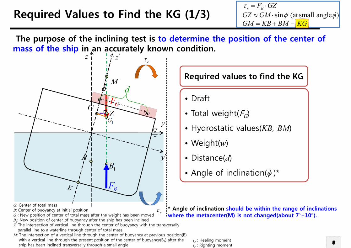
Required Values to Find the KG (1/3)
Required values to find the KG
• Draft
• Total weight(FG)
• Hydrostatic values(KB, BM)
• Weight(w)
• Distance(d)
• Angle of inclination(f )*
The purpose of the inclining test is to determine the position of the center of mass of the ship in an accurately known condition.
r BF GZt = ×sin (at small angle )GZ GM f f» ×
GM KB KGBM= + - KG
* Angle of inclination should be within the range of inclinations where the metacenter(M) is not changed(about 7°~10°).
G: Center of total massB: Center of buoyancy at initial positionG1: New position of center of total mass after the weight has been movedB1: New position of center of buoyancy after the ship has been inclinedZ: The intersection of vertical line through the center of buoyancy with the transversally
parallel line to a waterline through center of total massM: The intersection of a vertical line through the center of buoyancy at previous position(B)
with a vertical line through the present position of the center of buoyancy(B1) after the ship has been inclined transversally through a small angle
τe : Heeling momentτr : Righting moment
GF
1B
BF
1GZ
fM
d
rt
etz¢
y¢
y
z

6Planning Procedure of Naval Architecture and Ocean Engineering, Fall 2013, Myung-Il Roh
Required Values to Find the KG (2/3)
GF
1B
BF
1GZ
fM
r BF GZt = ×sin (at small angle )GZ GM f f» ×
GM KB KGBM= + - KG
Shift of center of total mass
Heeling moment produced by total weight
Righting moment produced by buoyant force
Static equilibrium of moment
Inclining test formula
d
1G
w dGGF×
=
1 cosh GF GGt f= ×
sinr B BF GZ F GMt f= × » ×
1 cos sinG BF GG F GMf f× = ×
1
tan tanG
GG w dGMFf f
×\ = =
×
rt
et
( ): G BStatic equilibrium F F=Q
z¢
y¢
y
z

7Planning Procedure of Naval Architecture and Ocean Engineering, Fall 2013, Myung-Il Roh
tanG
KG KB BM GMw dKB BM
F f
= + -×
= + -×
Required Values to Find the KG (3/3)r BF GZt = ×
sin (at small angle )GZ GM f f» ×GM KB KGBM= + - KG
KG
Known Known
Inclining experiment formula
The angle of inclination can be measured when we performthe inclining test.
tanG
w dGMF f
×=
×
Known
GF
1B
BF
1GZ
fM
d
rt
etz¢
y¢
y
z

8Planning Procedure of Naval Architecture and Ocean Engineering, Fall 2013, Myung-Il Roh
z¢
y¢
y
nz
Derivation of Inclining Test Formula (1/5)
BFGF
r BF GZt = ×sin (at small angle )GZ GM f f» ×
GM KB KGBM= + - KG
,K G
B
M
f
GZ0 0KN N N= +
csin os sinB By zKB df f d f= + × + ××
KN=
Byd Bzd
cosByd f sinBzd ff
sinKB f
1BB
,N Z0N,K Gw
GF
BF BF
These terms have positive effect to the restoring moment arm.
B Byd
Bzd
,K G ,N Z0N
1B
y
nzSuppose that the center of
mass is located at K. Then the KN represents the righting arm.

9Planning Procedure of Naval Architecture and Ocean Engineering, Fall 2013, Myung-Il Roh
z¢
y¢
y
z
0N
GF
Derivation of Inclining Test Formula (2/5)r BF GZt = ×
sin (at small angle )GZ GM f f» ×GM KB KGBM= + - KG
M
f
M
f
BF
B Byd
BzdBF
1B
sinGzd f- ×
GF
BF BF
B Byd
Bzd
,K G ,N Z0N
1BGF
ZG
Gzdf
GZ 'KN KG= -csin os sinB By zKB df f d f= + × + ××
This term has negative effect to the restoring moment arm.
GZ0 0KN N N= +
csin os sinB By zKB df f d f= + × + ××
KN=
K N'G
현재 이 이미지를 표시할 수 없습니다 .
GKG zd=
z¢
y¢
y
z

10Planning Procedure of Naval Architecture and Ocean Engineering, Fall 2013, Myung-Il Roh
d
z¢
y¢
y
z z¢
y¢
y
nz
0N
GF
Derivation of Inclining Test Formula (3/5)r BF GZt = ×
sin (at small angle )GZ GM f f» ×GM KB KGBM= + - KG
M
f
BF
B Byd
BzdBF
1B
0N
M
f
BF
B Byd
BzdBF
1B
Z
GF
GF
ZG
Gzd
K N'G
sinGzd f
G1Z
'G
Gyd
1 'GN
cosGyd f
f
This term has negative effect to the restoring moment arm.
1 1G Z 1' ' 'KN KG G G= - -csin os sinB By zKB df f d f= + × + ××
sinGzd f- ×
GZ 'KN KG= -csin os sinB By zKB df f d f= + × + ××
sinGzd f- ×
1G
cosGyd f- ×
GKG zd=
1 GGG yd=Gyd
cosGyd ff
1 'G'G
G
N
1Z
Z
1G
GF
sinGzd fK

11Planning Procedure of Naval Architecture and Ocean Engineering, Fall 2013, Myung-Il Roh
z¢
y¢
y
zbz
ny
by
nz
현재 이 이미지를 표시할 수 없습니다 .
0N
GF
Derivation of Inclining Test Formula (4/5)r BF GZt = ×
sin (at small angle )GZ GM f f» ×GM KB KGBM= + - KG
M
f
GF
M
f
BF
B Byd
BzdBF
1B
Z
GF
ZG
Gzd
K N'G
G
d
1Z
'GK
Gyd
1 'GN
cosGyd f
f
1 1G Z 1' ' 'KN KG G G= - -csin os sinB By zKB df f d f= + × + ××
sinGzd f- ×
1G
cosGyd f- ×
GKG zd=
1 GGG yd=
ü In n-frame, because the forces are acting on vertical direction, moment arm is yn-component.
cos sinsin cos
n bB B
n bB B
y yz z
f ff
d dd df
é ù é ùé ù=ê ú ê úê ú-ë ûë û ë û
cos sinn b bB B By y zd d f d f= +
nByd
nGyd-
cos sin( )
sin cosn
b
f ff
f f-é ù
=ê úë û
R
ü Rotational transformation matrix (b to n frame)
nyby
nzbz
f
cos( ) sin( )( )
sin( ) cos( )n
b
f ff
f f- - -é ù
= -ê ú- -ë ûR
ü Rotational transformation matrix (b to n frame)
ny
by
nzbz
-f
cos sinn b bG G Gy y zd d f d f= +
n n bP b P=r R r

12Planning Procedure of Naval Architecture and Ocean Engineering, Fall 2013, Myung-Il Roh
Derivation ofInclining Test Formula (5/5)
r BF GZt = ×sin (at small angle )GZ GM f f» ×
GM KB KGBM= + - KG
: Inclining test formula1
tan tanG
GG w dGMFf f
×\ = =
×
1 1G Z 1' ' 'KN KG G G= - -sin cos sinB BKB y zf d f d f= × + × + ×
sinGzd f- × cosGyd f- ×KN=
GKG zd=
1 GGG yd=
sinGZGM f
==
1sin cosGM GGf f= -
: Assume that 1f <<
1 1
1( sin cos )M G Z
GM GGd
f f= D ×= D × -
1sin cosGM GGf f=Static equilibrium of moment
1G
w dGGF×
=
sinKG f- 1 cosGG f-
Moment produced by total weight & buoyant force
Calculation of moment using “GZ”
GF
1B
BF
1GZ
fM
d
rt
etz¢
y¢
y
z
13Planning Procedure of Naval Architecture and Ocean Engineering, Fall 2013, Myung-Il Roh
Precautions to be Taken During the Inclining Test
Certain precautions must be taken to ensure that accuracy is obtained.
(1) The ship must be floating upright and freely without restraint from ropes.
(2) There should be no wind on the beam.
(3) All loose weights should be fixed.
(4) All cross-connections between tanks should be closed.
(5) Tanks should be empty or pressed full. If neither of these conditions is possible, the level of liquid in the tank should be such that the free surface effect is readily calculable and will remain sensibly constant through the experiment.
(6) The number of men on board should be kept to a minimum and they should be on the center line.
(7) Any mobile equipment used to move the weights across the deck must return to a known positions for each set of readings.

14Planning Procedure of Naval Architecture and Ocean Engineering, Fall 2013, Myung-Il Roh
Method of Measuringthe Angle of Inclination (1/2)
How can you measure the angle of inclinationwhen you perform the inclining test?
L
L: Length of plumb linePlumb: The line which is exactly vertical or perpendicular to
a level horizontal lineBatten: Long and thin strip of wood
f
Deflection
Deflection
Mark ! Mark !
DeflectiontanL
f\ =
z¢
y¢
y
z
IncliningtestformulatanG
w dGMF f
×=
×

15Planning Procedure of Naval Architecture and Ocean Engineering, Fall 2013, Myung-Il Roh
Method of Measuringthe Angle of Inclination (2/2)
* Reference: http://www.mchl.fr

16Planning Procedure of Naval Architecture and Ocean Engineering, Fall 2013, Myung-Il Roh
A ship is inclined by moving a weight of 40 tons a distance 8 m from the center line. A 12 m pendulum shows a deflection of 0.3 m.Displacement of the ship is 3,700 tons. If the KB is 5 m and BM is 14 m, what is the KG ? z¢
y¢
y
z
Example IncliningtestformulatanG
w dGMF f
×=
×
40 8 3.46tan 3700 0.025G
w dGMF f
× ×= = =
× ×
0.3tan 0.02512
f = =
5 14 3.4614.54
KG KB BM GM= + -= + -=
KG KB BM GM= + -
14.54[ ]KG m\ =1B
1GZ
f
M 8d m=
12m
0.3m
Solution)
17Planning Procedure of Naval Architecture and Ocean Engineering, Fall 2013, Myung-Il Roh
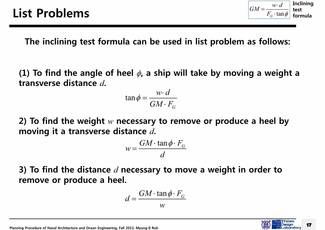
List Problems
The inclining test formula can be used in list problem as follows:
(1) To find the angle of heel f, a ship will take by moving a weight a transverse distance d.
2) To find the weight w necessary to remove or produce a heel by moving it a transverse distance d.
3) To find the distance d necessary to move a weight in order to remove or produce a heel.
tanG
w dGM F
f ×=
×
tan GGM Fwdf× ×
=
tan GGM Fdwf× ×
=
IncliningtestformulatanG
w dGMF f
×=
×