shine: simulator for satellite on-board high-speed
TRANSCRIPT

aerospace
Article
SHINe: Simulator for Satellite on-Board High-SpeedNetworks Featuring SpaceFibre andSpaceWire Protocols
Alessandro Leoni 1,* , Pietro Nannipieri 1 , Daniele Davalle 2 and Luca Fanucci 1
and David Jameux 3
1 Department of Information Engineering, University of Pisa, 56100 Pisa, Italy;[email protected] (P.N.); [email protected] (L.F.)
2 IngeniArs s.r.l., 5610 Pisa0, Italy; [email protected] Space Research and Technology Centre, European Space Agency, 2201 AZ Noordwijk, The Netherlands;
[email protected]* Correspondence: [email protected]; Tel.: +39-05027660
Received: 5 February 2019; Accepted: 6 April 2019; Published: 12 April 2019
Abstract: The continuous innovation of satellite payloads is leading to an increasing demand ofdata-rate for on-board satellite networks. In particular, modern optical detectors generate and needto transfer data at more than 1 Gbps, a speed that cannot be satisfied with standardized technologiessuch as SpaceWire. To fill this gap, the European Space Agency (ESA) is supporting the developmentof a new high-speed link standard, SpaceFibre. SpaceFibre provides a data-rate higher than 6.25 Gbps,together with the possibility to use multiple Virtual Channels running over the same physical link,each one configurable with flexible Quality of Service parameters. These features make a SpaceFibrenetwork very appealing but also complex to set up in order to achieve the desired end-to-endrequirements. To help this process, a Simulator for HIgh-speed Network (SHINe) based on theopen-source toolkit OMNeT++ has been developed and is presented in this paper. It supportsthe simulation of SpaceFibre and SpaceWire protocols in order to help both the final steps of thestandardization process and the system engineers in the setup and test of new networks. SHINeallows to precisely simulate common network metrics, such as latency and bandwidth usage, and itcan be connected to real hardware in a Hardware-in-the-Loop configuration.
Keywords: SpaceFibre; SpaceWire; network simulator; on-board satellite networks; OMNeT++
1. Introduction
Science and earth observation missions are experiencing a constant technology evolution, withtheir payload instruments needing higher and higher data-rates in order to stream the generated data.Typical examples are high-resolution optical payloads, as demonstrated in missions like MTG [1],Juice [2] and Plato [3]. In addition to the increased demand of data-rate, there is also a need to reducesatellite complexity by reducing the number of different on-board network technologies, and hopefullyusing one single network for all kinds of traffic in the future. This would bring a great harnessreduction, together with a noticeable simplification of the overall system management. SpaceFibre [4]is the solution, supported by the European Space Agency (ESA) [5], aiming at solving all theseproblems. It supports a link speed up to 6.25 Gbps per lane, with the possibility to run up to 16 lanesin parallel, on both copper and optical fibre. Moreover, SpaceFibre provides up to 32 Virtual Channels(VCs) per link, each one independently configurable with different Quality of Service parameters(priority level, reserved bandwidth, and assigned time-slots). The use of Virtual Channels allowscarrying different traffic classes using the same network technology. Hence, the network infrastructure
Aerospace 2019, 6, 43; doi:10.3390/aerospace6040043 www.mdpi.com/journal/aerospace

Aerospace 2019, 6, 43 2 of 16
can be effectively shared among different applications, even when the requirements are completelydifferent. In particular, it would be possible to use a SpaceFibre network both for payload applications(usually requiring high data-rates but with little time requirements) and for platform applications(usually requiring low data-rates but with stringent time and reliability requirements). These featuresrepresent a big step forward in comparison with older technologies such as SpaceWire [6,7] andmake the configuration of a SpaceFibre network undoubtedly complex. Moreover, The core layersof the SpaceFibre standard have already underwent public review and are expected to be releasedas a standard in 2019, while the SpaceFibre network layer is still under standardization process andsome features have yet to be defined. In order to help to finalize the standard and to simplify thedevelopment of new SpaceFibre networks, the Simulator for HIgh-speed Networks (SHINe) hasbeen developed [8]. SHINe is a discrete event simulator supporting both SpaceFibre and SpaceWireprotocols and it is entirely based on the open-source framework OMNeT++ [9]. With SHINe, it ispossible to easily deploy a network via drag&drop from a palette and simulate it, collecting andanalysing the results. Being based on OMNeT++, SHINe is completely written in C++ and it iseasily extensible, allowing the user to develop custom nodes to use together with the existing ones.SHINe implements not only the basic SpaceFibre and SpaceWire protocols, but it also offers a RoutingSwitch node, both Remote Memory Access Protocol (RMAP) Target and RMAP Initiator nodes, and anadvanced Hardware-in-the-Loop mechanism to connect physical devices to the simulator.
After this introduction, Section 2 presents an overview of the already existing network simulatorsin this field. Section 3 provides internal details of the SHINe software architecture. Section 4 shows anexample of a simple network setup, briefly going through all the steps needed to define and simulate anetwork. Finally, the conclusions are drawn in Section 5.
2. Related Works
There are other simulators, presented in Table 1, already available for the simulation ofSpaceWire and SpaceFibre networks. Among them, Modelling of SpaceWire Traffic (MOST) [10],developed by Thales Alenia Space (TAS), is probably the most used. MOST is based on the toolkitOPNET, hence it requires an annual license to be used, while OMNeT++ requires a license only forcommercial applications and it is free for academic and research projects. Thanks to its long-termdevelopment, MOST provides a wide library of SpaceWire-related products, such as the SMCS116SpW,the SMCS332SpW, the Remote Terminal Controller (RTC) and the SpW-10X Switch. It also supportsSpacefibre endpoints in its OPNET version. In comparison, SHINe provides only ideal components.Currently, TAS is porting MOST from OPNET to NS-3, which does not require the payment of a license.It appears that support on SpaceFibre has been recently added [11], however, no detailed publicinformation are available. Another important simulator is SANDS [12], developed by Saint-PetersburgUniversity of Aerospace Instrumentation (SUAI). SANDS aims to support the topology design forSpaceWire networks taking into account several parameters, such as the required fault-tolerancelevel, total network mass including cables and nodes, and power consumption. SANDS also allowssimulating the network, using its SystemC engine, either at bit level or at packet level, as well asproviding support for the generation of the scheduling tables for scheduling Quality of Service ofSTP-ISS [13] transport protocol running on top of SpaceWire.
While each simulator has its own strength, SHINe is the only one supporting both SpaceFibre andSpaceWire that is free, making it a very good product to help the development of such protocols.
Table 1. Summary of the main SpaceWire/SpaceFibre network simulators available.
Simulator Toolkit/Language SpaceWire/SpaceFibre Support
SHINe OMNeT++ (C++) SpW/SpFiMOST (NS-3) NS-3 (C++) SpW/SpFi
MOST (OPNET) OPNET (C) SpW/SpFiSANDS Own/SystemC SpW

Aerospace 2019, 6, 43 3 of 16
3. SHINe Core Building Blocks
This section provides detailed information on the software architecture of SHINe. After a shortoverview of the main mechanisms behind the simulator, the core building blocks are illustrated.
3.1. SHINe Software Architecture
The driving idea during the development of SHINe was to create a tool providing the buildingblocks to easily set up a SpaceFibre or SpaceWire network infrastructure, while the definition of theapplications connected to this network is left up to the user. With this goal in mind, the main efforthas been spent simplifying the Application-to-Network interface, hence most of the protocol-relatedmetrics are observable and automatically recorded (packet latency, link usage, Flow Control Token(FCT) credit, generated packet size, received packet size). The main two core building blocks providedby SHINe are the SpaceFibre Endpoint and the SpaceWire Endpoint. They offer a C++ interfacecompliant with the service interface described in the two standards, completely hiding the protocolsdetails to the application. Internally, both the SpaceFibre Endpoint and the SpaceWire Endpointmodules are composed by several nested submodules (Port and Codec), each one reducing theabstraction level down to the actual C++ implementation of the standard specifications. However,the application can treat the Endpoints as black boxes and it is not necessary for the user to know thedetails of the SpaceFibre and the SpaceWire standards.
As shown in Figure 1, the user-defined Application must extend a specific C++ interface in orderto be connected to the Endpoints. In such a way, it is possible for the Endpoint to call “callback”functions of the application without knowing their actual implementation. For example, the Endpointmay notify through a callback that new data is ready to be read or that the transmission buffer has afree slot to send new data.
Figure 1. Interaction between User Application and SpaceFibre or SpaceWire Endpoint.
3.2. SpaceFibre Endpoint
The SpaceFibre Endpoint module is the core building block in SHINe to instantiate a fully-functionalSpaceFibre port. As shown in Figure 2, it provides two input/output gates for the connection with theupper layer application and one input/output gate representing the physical SpaceFibre connector.Note that there are two gates towards the upper layer, one for the NChar transmission (appPacket) andone for the Broadcast messages transmission (appBroadcast), allowing using two different applicationsin case the user prefers to model the two interfaces separately. In order to be connected to a SpaceFibreEndpoint, an application must extend the ToSpfiApplication C++ abstract class. This class representsthe interface that the Endpoint can use to notify about the availability of new NChars or Broadcast

Aerospace 2019, 6, 43 4 of 16
messages to read. A SpaceFibre Endpoint automatically collects several metrics about network usage,such as: (i) packet latency; (ii) packet inter-arrival time; (iii) packet inter-transmission time; and(iv) broadcast message latency.
Figure 2. Internal architecture of a SpaceFibre Endpoint.
The SpaceFibre Endpoint is a versatile module and it can include either a SpaceFibre Port or a FirstIn Firt Out (FIFO) Port, as specified in the standard, depending on a user defined parameter. The FIFOPort does not implement any specific transfer protocol and it is only capable of transferring NCharsbetween the two far-ends, simulating a generic FIFO-like protocol but offering the same interface to theapplication of a SpaceFibre Port. Note that it does not provide a way to transmit Broadcast messagesas well as a flow control mechanism, so data may be lost. When the SpaceFibre Port is chosen, thewhole SpaceFibre protocol as described in the standard is used. In particular, the following featuresare supported:
• Fault Detection Isolation and Recovery (FDIR) mechanism, with retransmission in case of(injected) errors;
• Flow Control Mechanism (FCT);• IDLE words, IDLE Frames and SKIP words insertion (See [4] for details on SpFi control words);• Multilane layer support;• Upper lane layer support, excluding 8b/10b encoding and serialisation. The OMNeT++ messages
exchanged between SpaceFibre Endpoints represent an abstraction of the 40-bits SpaceFibrewords. The choice to simulate at “word level” instead of at “bit level” has been taken because,from a networking standpoint, the simulation of the physical layer does not add any additionalvalue to the results but it greatly affects the simulation time;
Both the Lane and the Multilane Layers can be bypassed to save additional simulation time ifthe user is not interested in simulating their behaviour and the overhead they add to the protocol.Each deployed SpaceFibre Endpoint can be independently configured through all the parametersforeseen by the standard, such as the Expected Bandwidth, the Priority levels, the Assigned Timeslots,etc., plus additional parameters such as buffers size and number of lanes. It is also possible to define atransmission and reception delay at the interface with the link to simulate internal buffers or pipelinestages in the data-path.

Aerospace 2019, 6, 43 5 of 16
3.3. SpaceWire Endpoint
The SpaceWire Endpoint plays a role similar to the SpaceFibre Endpoint and it is the building blockproviding a fully functional implementation of the SpaceWire standard. From the user perspective,the two kinds of Endpoints offer a similar interface. A SpaceWire Endpoint, whose architecture isshown in Figure 3, provides two input/output gates for the connection with the upper layer applicationand one input/output gate representing the physical connector. The connection with the application issplit in two gates, one for the NChars transmission and reception and one for the TimeCodes, henceit is possible to use two different applications for the packet stream and the TimeCodes. Note thatInterrupts are not currently supported in SHINe. The SpaceWire Endpoint internally instantiate aTimeCode Manager, which is responsible for:
• keeping trace of the value of the next TimeCode to send;• storing the value of the latest TimeCode received, in order to be able to validate (or discard) the
next one. As specified in the standard, a TimeCode is valid when its value is equal to the value ofthe previous one plus one. Only if this condition is satisfied the application is notified about thereception of a new TimeCode.
Following the same logic of the SpaceFibre Endpoint, an application must extend theToSpwApplication C++ abstract class in order to be connected to a SpaceWire Endpoint. In addition, inthis case, several network related statistics are automatically collected by SHINe.
Figure 3. Internal architecture of a SpaceWire Endpoint.
A SpaceWire Endpoint can instantiate either a SpaceWire Port or a FIFO Port, keeping the sameinterface towards the application. In the former case, a complete SpaceWire Codec is simulated inC++, while in the latter case a generic FIFO-like protocol takes place, with the same limitations alreadydescribed for SpaceFibre. When the SpaceWire Port is used, the most remarkable functions are:
• Simulation of the Initialisation phase, according to the initialisation state machine described inthe standard;
• Flow Control Mechanism (FCTs);

Aerospace 2019, 6, 43 6 of 16
• Error detection, in case a character is received when not expected or it contains an invalid field;• ESC (see [6] for details) character insertion when no data is available to be sent;
Two adjacent SpaceWire Endpoints communicate exchanging OMNeT++ messages representingthe characters sent by the Codecs. Note that, differently from SpaceFibre, in SpaceWire the differentkinds of characters have different bit sizes. For example, an NChar is 10 bits long considering theParity and Control bits, while an FCT is only 4 bits long, hence they take a different amount of time tobe transmitted. The Endpoint is highly customizable through several parameters, such as transmissionand reception data-path delay, initialisation link speed, buffers size, and others.
3.4. Routing Switch
The core elements in a network are naturally the Routing Switches. One of the most critical pointsin the study and development of the SpaceFibre Network Layer is its interoperability with legacySpaceWire networks. A realistic scenario in the transition phase between the two technologies foreseesthe use of SpaceFibre as a high-speed backbone with some of the nodes connected through SpaceFibreand some others through SpaceWire. While the two protocols are compatible from the packet formatstandpoint, there are no specifications about:
• how to bridge Broadcast messages with the TimeCodes;• how to forward packets between the two domains, where in SpaceFibre a packet is always
associated to its Virtual Channel while in SpaceWire it is not;
The Routing Switch available in SHINe allows connecting both SpaceFibre and SpaceWireEndpoints and implements realistic solutions to the open points listed above.
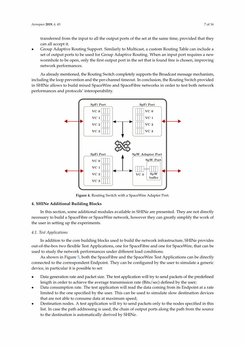
An overview of the Routing Switch architecture is shown in Figure 4. A Routing Switch comprisesa user defined number of ports of three possible kinds: (i) SpaceFibre Ports; (ii) SpaceWire AdapterPorts; or (iii) FIFO Ports. All of them share the same SpaceFibre interface to the internal SwitchingMatrix, but they differ in their implementations. In particular, the SpaceWire Adapter Port acts as awrapper around a normal SpaceWire Port, making it to look like a SpaceFibre Port with only one VirtualChannel. Moreover, this wrapper is responsible for the bridging of Broadcast messages accordingto the following rule: whenever a TimeCode is received from the underlying SpaceWire port, it iswrapped into a Broadcast message of a specific type and then forwarded to the Switching Matrix to bepropagated. Vice-versa, whenever the Switching Matrix tries to propagate a Broadcast message to aSpaceWire Adapter Port, the message is checked for its type: if it contains a TimeCode, the messageis unwrapped and the TimeCode is sent, otherwise it is simply dropped. This simple mechanismmakes possible for a SpaceFibre backbone to transparently carry TimeCodes. Moreover, the automaticloop prevention foreseen by the SpaceFibre standard guarantees that no multiple copies of the sameTimeCode are propagated.
The SHINe Routing Switch implements all the features required by the SpaceFibre standards.In particular, it supports:
• Path and Logical Addressing. When using Path Addressing, the output port of the Routing Switchis directly written in the packet header. When using Logical Addressing, however, a RoutingTable is necessary to associate the logical addresses to the output ports. The table can be providedby the user as a comma-separated file or can be built automatically by SHINe using Dijkstraalgorithm in order to speed up the setup of the network;
• Virtual Network Mapping. For each Virtual Channel of each port, the user can specify the VirtualNetwork it belongs to. According to the SpaceFibre standard, packets can flow only throughVirtual Channels belonging to the same Virtual Network. Note that, thanks to the RoutingSwitch implementation in SHINe, the single Virtual Channel of a SpaceWire Adapter Ports can bemapped into any Virtual Network.
• Multicast Support. In case the user decides to specify a custom Routing Table, he can define,for a specific logical address, a Multicast set of output ports. When Multicast is used, an NChar is
Aerospace 2019, 6, 43 7 of 16
transferred from the input to all the output ports of the set at the same time, provided that theycan all accept it.
• Group Adaptive Routing Support. Similarly to Multicast, a custom Routing Table can include aset of output ports to be used for Group Adaptive Routing. When an input port requires a newwormhole to be open, only the first output port in the set that is found free is chosen, improvingnetwork performances.
As already mentioned, the Routing Switch completely supports the Broadcast message mechanism,including the loop prevention and the per-channel timeout. In conclusion, the Routing Switch providedin SHINe allows to build mixed SpaceWire and SpaceFibre networks in order to test both networkperformances and protocols’ interoperability.
Figure 4. Routing Switch with a SpaceWire Adapter Port.
4. SHINe Additional Building Blocks
In this section, some additional modules available in SHINe are presented. They are not directlynecessary to build a SpaceFibre or SpaceWire network, however they can greatly simplify the work ofthe user in setting up the experiments.
4.1. Test Applications
In addition to the core building blocks used to build the network infrastructure, SHINe providesout-of-the-box two flexible Test Applications, one for SpaceFibre and one for SpaceWire, that can beused to study the network performances under different load conditions.
As shown in Figure 5, both the SpaceFibre and the SpaceWire Test Applications can be directlyconnected to the correspondent Endpoint. They can be configured by the user to simulate a genericdevice, in particular it is possible to set:
• Data generation rate and packet size. The test application will try to send packets of the predefinedlength in order to achieve the average transmission rate (Bits/sec) defined by the user;
• Data consumption rate. The test application will read the data coming from its Endpoint at a ratelimited to the one specified by the user. This can be used to simulate slow destination devicesthat are not able to consume data at maximum speed;
• Destination nodes. A test application will try to send packets only to the nodes specified in thislist. In case the path addressing is used, the chain of output ports along the path from the sourceto the destination is automatically derived by SHINe.

Aerospace 2019, 6, 43 8 of 16
Note that in case of SpaceFibre test application, the parameters described above can be specifiedindividually for each virtual channel. Another possible usage of these example applications is tovalidate the correctness of the packets content: the generated packets contain incremental integers thatare checked for integrity on reception. In case of errors in the transmission (e.g., bugs in the code orerror injection on links), the receiving application raises an error.
Figure 5. SpaceFibre and SpaceWire Test Applications.
4.2. RMAP Modules
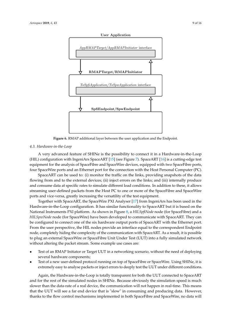
Remote Memory Access Protocol (RMAP) [14] is the most common protocol used directly on topof SpaceWire. It allows accessing a remote memory region on the target device in several operationmodes. The RMAP standard specifies two types of device: i) the Initiator, which is responsible forissuing the requests and ii) the Target, which must react to the requests and, if necessary, send a replyback to the Initiator. SHINe fully implements the RMAP standard specifications, for both the Initiatorand the Target. They are implemented as application modules for the SpaceFibre and SpaceWireEndpoints, actually creating an additional layer between the final application of the user and thenetwork infrastructure (see Figure 6).
The top-level user application, in order to be connected with the RMAP modules, must extendthe C++ abstract classes AppRMAPTarget or AppRMAPInitiator, depending on the case. Extendingthese interfaces allows the underlying RMAP layer to call callback functions of the user application,for example when a new complete RMAP Request is received. Among the other features, the SHINeRMAP implementation supports:
• All the three RMAP commands: Write, Read and Read-Modify-Write;• Both Acknowledged and non-Acknowledged commands. In the first case, an Ack is automatically
sent back by the RMAP Target to the Initiator with the status of the transaction (containing anerror code in case something went wrong). In the second case, the Initiator is not notified aboutthe result of the transaction;
• Both Verified and non-Verified commands. The data field of Verified commands is covered by aCyclic redundancy Check (CRC) code, which is checked before executing the Read or Write request;
• Multiple ongoing requests support for the RMAP Initiator. The Initiator can send multiplerequests before receiving the associated replies. The pending requests are identified, associating aTransaction Identifier ID to them;
Hence, SHINe provides easy to use RMAP blocks with complete functionalities that can be usedto simulate any kind of RMAP transaction for both SpaceFibre and SpaceWire.
Aerospace 2019, 6, 43 9 of 16
Figure 6. RMAP additional layer between the user application and the Endpoint.
4.3. Hardware-in-the-Loop
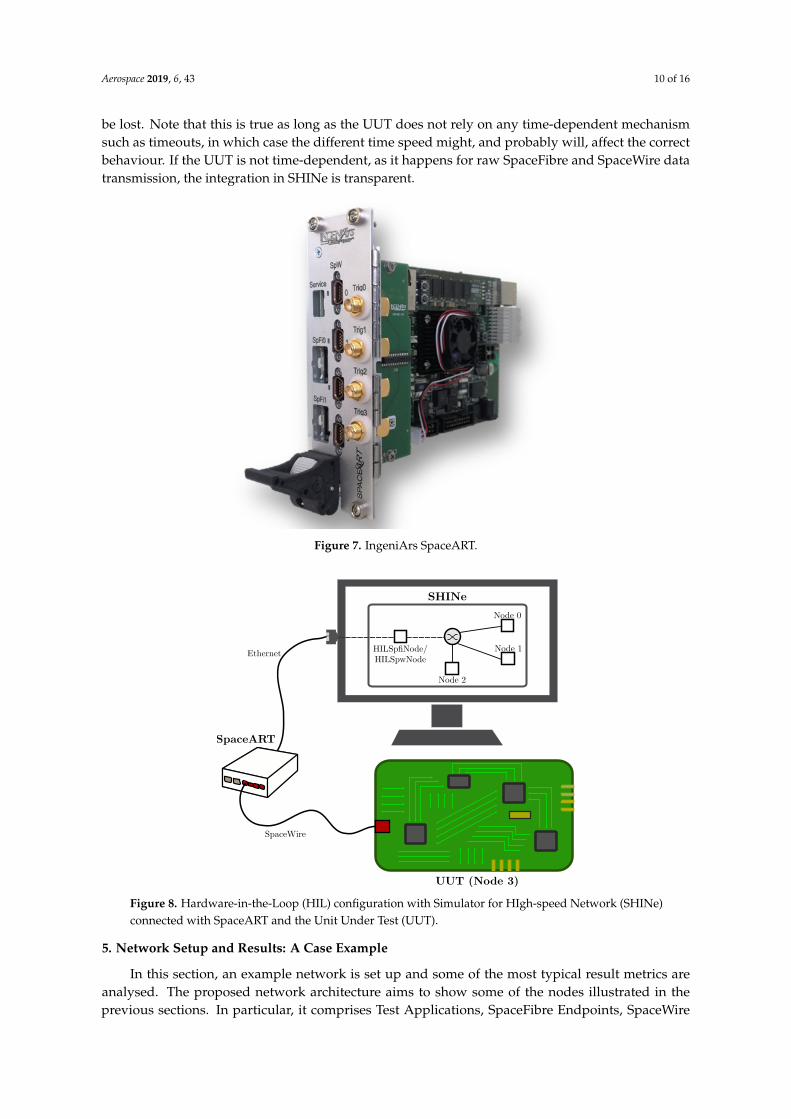
A very advanced feature of SHINe is the possibility to connect it in a Hardware-in-the-Loop(HIL) configuration with IngeniArs SpaceART [15] (see Figure 7). SpaceART [16] is a cutting-edge testequipment for the analysis of SpaceFibre and SpaceWire devices, equipped with two SpaceFibre ports,four SpaceWire ports and an Ethernet port for the connection with the Host Personal Computer (PC).
SpaceART can be used to: (i) monitor the traffic on the links, providing snapshots of the dataflowing from and to the external devices; (ii) inject errors on the links; and (iii) internally produceand consume data at specific rates to simulate different load conditions. In addition to these, it allowsstreaming user-defined packets from the Host PC to one or more of the SpaceFibre and SpaceWireports and vice-versa, greatly increasing the versatility of the test equipment.
Together with SpaceART, the SpaceWire PXI Analyser [17] from IngeniArs has been used in theHardware-in-the-Loop configuration. It has similar functionality to SpaceART but it is based on theNational Instruments PXI platform. As shown in Figure 8, a HILSpfiNode node (for SpaceFibre) and aHILSpwNode node (for SpaceWire) have been developed to communicate with SpaceART. They canbe configured to connect one of the six hardware output ports of SpaceART with the Ethernet port.From the user perspective, the HIL nodes provide an interface equal to the correspondent Endpointnode, completely hiding the complexity of the communication with SpaceART. As a result, it is possibleto plug an external SpaceWire or SpaceFibre Unit Under Test (UUT) into a fully simulated networkwithout altering the packet stream. Some example use cases are:
• Test of an RMAP Initiator or Target UUT in a networking scenario, without the need of deployingseveral hardware components;
• Test of a new user-defined protocol running on top of SpaceFibre or SpaceWire. Using SHINe, it isextremely easy to analyse packets or inject errors to deeply test the UUT under different conditions.
Again, the Hardware-in-the-Loop is totally transparent for both the UUT connected to SpaceARTand for the rest of the simulated nodes in SHINe. Because obviously the simulation speed is muchslower than the data-rate of a real device, the communication will not happen in real-time. This meansthat the UUT will see a far end device that is "slow" in consuming and producing data. However,thanks to the flow control mechanisms implemented in both SpaceFibre and SpaceWire, no data will
Aerospace 2019, 6, 43 10 of 16
be lost. Note that this is true as long as the UUT does not rely on any time-dependent mechanismsuch as timeouts, in which case the different time speed might, and probably will, affect the correctbehaviour. If the UUT is not time-dependent, as it happens for raw SpaceFibre and SpaceWire datatransmission, the integration in SHINe is transparent.
Figure 7. IngeniArs SpaceART.
Figure 8. Hardware-in-the-Loop (HIL) configuration with Simulator for HIgh-speed Network (SHINe)connected with SpaceART and the Unit Under Test (UUT).
5. Network Setup and Results: A Case Example
In this section, an example network is set up and some of the most typical result metrics areanalysed. The proposed network architecture aims to show some of the nodes illustrated in theprevious sections. In particular, it comprises Test Applications, SpaceFibre Endpoints, SpaceWire

Aerospace 2019, 6, 43 11 of 16
Endpoints, a Routing Switch and it makes use of the Hardware-in-the-Loop capability. The goal is toshow an example of usage of SHINe from the user perspective.
5.1. Network Setup
The first step in the simulation of the network is its setup, intended as the deployment of thenodes composing the network itself. This step can be done either graphically, via drag&drop from apalette, or textually, using the internal language of OMNeT++ to describe network connections andparameters (called NED). In the same way, the connections between the nodes are created. As alreadymentioned, the network uses the Hardware-in-the-Loop capability. The SpaceWire PXI Analyser isused to simulate a Unit Under Test. It is connected to SpaceART through a SpaceWire cable, andSpaceART acts as a bridge towards the simulator. The PXI analyser can be configured to generateand/or consume data at a specific rate.
5.2. Nodes Configuration
After the nodes deployment, they must be configured in order to represent the scenario that theuser wants to simulate. OMNeT++ allows configuring a node in two ways: (i) directly modifying theNED file of the network, either via text editor or through the OMNeT++ GUI [18] (see Figure 9) or(ii) overwriting the parameters in the .ini file (initialisation file).
Figure 9. Network setup and parameter configuration for a SpaceFibre endpoint and its internalCompression/Decompression module (CODEC).
While from a practical point of view the two methods are idempotent, changing the NED filebetter suits “architectural” changes (e.g., the number of Virtual Channels of a node), while changingthe initialisation file is preferable to configure “per-run” parameters (e.g., the Expected Bandwidth of aVirtual Channel).
In this example (see Figure 10), the network comprises the following nodes:

Aerospace 2019, 6, 43 12 of 16
• a simulated SpaceFibre data sink (spfiEndpointSink + spfiSink) with four Virtual Channels.The application does not produce any data but consumes all incoming packets as soon as theyare received;
• a simulated SpaceFibre data source (spfiEndpointSource + spfiSource) with four Virtual Channels.The application tries to send data on every Virtual Channel at maximum rate to the sink;
• a simulated SpaceWire data source (spwEndpointSource + spwSource). The application tries to senddata on the link at maximum rate to the sink;
• an external hardware node (spwEndpointHIL + HILSpw), realising the bridge to the SpaceWire PXIanalyser. The PXI analyser tries to send data at maximum rate to the sink;
• a Routing Switch, comprising two SpaceFibre ports and two SpaceWire ports.
All the SpaceFibre links are configured with a link rate of 2.5 Gbps (2 Gbps of useful data, takinginto account the 8b/10b encoding), while the SpaceWire links (both simulated and physical) are set to50 Mbps (40 Mbps of useful data, taking into account the parity and control bits).
Figure 10. Example network simulated in SHINe.
Table 2 summarizes the main configuration parameters of the ports, with the Expected Bandwidthsand the generated packets size. No protocol is being used on top of SpaceFibre and SpaceWire, so rawdata are generated. The Expected Bandwidth is a SpaceFibre parameter defining the percentage ofthe total link bandwidth assigned to each Virtual Channel. As far as a Virtual Channel has data tosend, this mechanism guarantees at least the assigned portion of the link capacity to that VirtualChannel. In case it has no data to send, this capacity is split among the other Virtual Channels. Table 3represents the Virtual Network mapping inside the Routing Switch. Note that the SpaceWire portsare mapped to Virtual Network 1, so the wormholes will be established with Virtual Channel 1 of theoutput SpaceFibre port.
Table 2. Ports configuration parameters.
Port Expected Bandwidth (per VC) Packet Length (Bytes)
SpFi Data Source [10%, 20%, 30%, 35%] 100,000 (all VCs)SpW Data Source - 100,000HIL Data Source [10%, 20%, 30%, 35%] 100,000 (all VCs)
Routing Switch (SpFi output port to Sink) [10%, 20%, 30%, 35%] -
Table 3. Routing Switch Virtual Networks.
Port Virtual Channels to Virtual Networks mapping
SpFi Data Source Port [0, 1, 2, 3]SpW Data Source Port [1]HIL Data Source Port [1]SpFi Data Sink Port [0, 1, 2, 3]

Aerospace 2019, 6, 43 13 of 16
5.3. Simulation Run
Once the network is ready, the simulation can be run. OMNeT++ allows running the simulationboth graphically and from command line. In case the graphical environment is chosen, different simulationspeeds can be selected to trade-off execution time versus debug information printed on screen.
5.4. Simulation Results
During the simulation, SHINe collects several measurements to be analysed at the end of therun, either directly in OMNeT++ through the embedded data manipulation and visualization tool(scavetool) or exporting the data for further elaboration (e.g., in MATLAB or GNU Octave). In thefollowing, some measurements related to the SpaceFibre output port of the Routing Switch connectedto the Sink node are shown and analysed. They are:
• Virtual Channels utilization. This parameter is analysed to prove the correct implementation ofthe SpaceFibre protocol, especially for what concerns the Quality of Service mechanism.
• End-to-end packet latency. From this value, the impact of the wormhole routing can be studied,taking into account the interaction between the SpaceWire and SpaceFibre protocols.
For what concerns the Virtual Channel (VC) utilization in the Routing Switch output port, it isimportant to check the simulated results (see Figure 11) against the Expected Bandwidth values.It can be seen that VC0, VC2 and VC3 use just slightly more link capacity than expected, with theexpected being 10%, 30% and 35% for VC0, VC1 and VC3 respectively, while VC1 is under-usingits bandwidth. This happens because VC1 is shared between the SpaceFibre and the two SpaceWireData Sources. When the <OutputPort, VC> of the Routing Switch is assigned to one of the SpaceWirenodes, NChars are transferred slowly, precisely at 40 Mbps (i.e., 80% of the SpaceWire input link rate).This value is much lower than the 20% of the SpaceFibre output link rate (i.e., 400 Mbps) assignedto Virtual Channel 1, causing the Virtual Channel to slowly accumulate credit. Instead, when VC1of the SpaceFibre Data Source gets the wormhole, the accumulated credit is spent, causing a shortutilization peak.
Figure 11. Link utilization per Virtual Channel of the Routing Switch SpaceFibre output port.
The other metric under study is the packet latency from each source to the sink. The latencyis measured from the time the packet enters the transmission FIFO in the source node to the timethe last byte is read out of the reception FIFO in the destination node. The results are shown inTable 4. As expected, the packets originated from the SpaceFibre source by VC0, VC2 and VC3 are notinfluenced by the SpaceWire nodes transmitting, being allocated to different Virtual Networks andtherefore not sharing any network resource with them. Hence, the latency they experiment depends

Aerospace 2019, 6, 43 14 of 16
only on the link speed and the portion of the link bandwidth (Expected Bandwidth) they have allocated(the larger the Expected Bandwidth, the faster a packet is transmitted along the link and thus theshorter its latency).
Table 4. Packet latency for each source node to the sink (seconds).
Source Node/VC Minimum Average Maximum
SpFi, VC0 3.211 × 10⁻³ 3.389 × 10⁻³ 3.701 × 10⁻³
SpFi, VC1 2.020 × 10⁻³ 34.910 × 10⁻³ 40.519 × 10⁻³
SpFi, VC2 1.086 × 10⁻³ 1.189 × 10⁻³ 1.520 × 10⁻³
SpFi, VC3 0.915 × 10⁻³ 0.997 × 10⁻³ 1.311 × 10⁻³
SpW Sim 40.201 × 10⁻³ 40.688 × 10⁻³ 41.845 × 10⁻³
SpW HIL 40.112 × 10⁻³ 40.392 × 10⁻³ 41.448 × 10⁻³
The packets originated by the two SpaceWire nodes (the simulated one and the HIL) have higherlatency, due to the packets being transmitted over much slower SpaceWire links. Finally, a similarlatency is obtained for the SpaceFibre source node on VC1. This happens because it shares the VirtualChannel with the two SpaceWire nodes and, when they get the wormhole in the Routing Switch,the SpaceFibre packet has to wait for their slow complete transmission.
The results match exactly with the expected values, proving the correct implementation of boththe SpaceFibre Quality of Service mechanism and the functionality of the Hardware-in-the-Loop.
6. Conclusions
In this paper, the simulator SHINe for SpaceFibre and SpaceWire networks has been presented.The main building blocks needed to set up a network have been illustrated in detail, together withsome additional modules implementing advanced features like RMAP and the Hardware-in-the-Loopcapability. Finally, all the steps to run a simulation of an example network have been shown, from thenode deployment to the analysis of the results.
SHINe allows to quickly and easily implement and test SpaceFibre or SpaceWire-based networksand evaluate typical metrics such as packet latency and link utilization, as well as protocol-relatedmeasurements (FCT counters and buffer status). The simulator, based on the open-source frameworkOMNeT++, is modular and easily extensible, allowing the user to implement custom applications.SHINe can effectively help both the study of networks before their actual implementation and thedevelopment of new protocols on top of SpaceFibre and SpaceWire.
Author Contributions: The research and the article preparation have been carried out by A.L. and P.N. under thesupervision of L.F., D.D. and D.J.
Funding: IngeniArs SpaceFibre technologies have been developed in the framework of the SIMPLE project(Spacefibre IMPLementation design & test Equipment). This project received funding from the European UnionsHorizon 2020 research and innovation programme under Grant Agreement No. 757038.
Conflicts of Interest: The authors declare no conflict of interest.
Abbreviations
The following abbreviations are used in this manuscript:
BC BroadcastCDH Command and Data handlingCRC Cyclic Redundancy CheckECSS European Cooperation for Space StandardizationEGSE Electrical Ground Segment EquipmentsESA European Space Agency

Aerospace 2019, 6, 43 15 of 16
FCT Flow Control TokenFDIR Fault Detection Isolation and RecoveryFPGA Field Programmable Gate ArrayIn BCB In Broadcast Channel BufferLUT Look-Up-TablesMAC Medium Access ControllerOut BCB Out Broadcast Channel BufferQoS Quality of ServiceReg RegisterSAR Synthetic Aperture RadarsVCB Virtual Channel BuffersSHINE Simulator for HIgh-speed NetworksRMAP Remote memory access protocolMOST Modelling of SpaceWire TrafficSPW SpaceWireSPFI SpaceFibreFIFO First In First OutUUT Unit Under TestSUAI Saint-Petersburg University of Areospace Instrumentation
References
1. Lorenzini, S.; Bardazzi, R.; Di Giampietro, M.; Feresin, F.; Taccola, M.; Perez Cuevas, L. Optical design of theLightning Imager for MTG. In Proceedings of the International Conference on Space Optics, Ajaccio, France,9–12 October 2012.
2. Della Corte, V.; Schmitzb, N.; Zusic, M.; Castro, J.M.; Leese, M.; Debei, S.; Magrin, D.; Michalik, H.;Palumbo, P.; Jaumann, R.; et al. The JANUS camera onboard JUICE mission for Jupiter system opticalimaging. In Proceedings of the Space Telescopes and Instrumentation Conference, Montreal, QC, Canada,22 June 2014.
3. Laubier, D.; Bodin, P.; Pasquier, H.; Fredon, S.; Levacher, P.; Vola, P.; Buey, T.; Bernardi, P. The PLATO camera.In Proceedings of the International Conference on Space Optics, Ajaccio, France, 9–12 October 2012.
4. SpaceFibre Standard ECSS-E-ST-50-11C-DIR1. Available online: https://ecss.nl/standard/ecss-e-st-50-11c-dir1/ (accessed on 21 January 2019).
5. Siegle, F.; Habinc, S.; Both, J. SpaceFibre Port IP Core (GRSPFI): SpaceFibre, poster paper. In Proceedings ofthe 7th International SpaceWire Conference, Yokohama, Japan, 24–28 October 2016; pp. 1–5.
6. SpaceWire Standard ECSS-E-ST-50-12C. Available online: https://ecss.nl/standard/ecss-e-st-50-12c-spacewire-links-nodes-routers-and-networks/ (accessed on 21 January 2019).
7. Saponara, S.; Fanucci, L.; Tonarelli, M.; Petri, E. Radiation Tolerant SpaceWire Router for Satellite On-BoardNetworking. IEEE Aeros. Electron. Syst. Mag. 2017, 22, 3–12. [CrossRef]
8. Leoni, A.; Fanucci, L.; Jameaux, D. Simulator for HIgh-speed Networks (SHINe): An OMNeT++ simulatorfor SpaceFibre and SpaceWire Networks. In Proceedings of the SpaceWire Conference, Los Angeles, CA,USA, 14–18 May 2018.
9. OMNET++. Available online: https://omnetpp.org/ (accessed on 21 January 2019).10. Dellandrea, B.; Gouin, B.; Parkes, S.; Jameux, D. MOST: Modelling of SpaceWire and SpaceFibre
Traffic—Applications and Operations: On-Board Segment. In Proceedings of the DAta Systems in Aerospaceconference, Warsaw, Poland, 3–5 June 2014.
11. Jaume, J.A. Modelling of SpaceFibre Networks. Master’s Thesis, Universitat Politècnica de CatalunyaBarcelonatech, Barcelona, Spain, 30 October 2018.
12. Sheynin, Y.; Olenev, V.; Lavrovskaya, I.; Korobkov, I. Computer-Aided Design System for On-boardSpaceWire Networks Simulation and Design. In Proceedings of the 20th Conference of Open InnovationsAssociation, Saint-Petersburg, Russia, 3–7 April 2017.
13. Sheynin, Y.; Olenev, V.; Lavrovskaya, I.; Korobkov, I.; Kochura, S.; Openko, S.; Dymov, D. Second revision ofthe STP-ISS transport protocol for on-board spacewire networks. In Proceedings of 2015 17th Conference ofOpen Innovations Association (FRUCT), Yaroslavl, Russia, 20–24 April 2015, pp. 192–200.

Aerospace 2019, 6, 43 16 of 16
14. RMAP Standard ECSS-E-ST-50-52C. Available online: https://ecss.nl/standard/ecss-e-st-50-52c-spacewire-remote-memory-access-protocol-5-february-2010/ (accessed on 21 January 2019).
15. Davalle, D.; Leoni, A.; Dello Sterpaio, L.; Fanucci, L. Design and implementation of test equipment forSpaceFibre links: SpaceFibre, short paper. In Proceedings of the 7th International SpaceWire Conference,Yokohama, Japan, 24–28 October 2016; pp. 1–5.
16. SpaceART Webpage. Available online: https://www.ingeniars.com/english/products/space/spaceart-en.html (accessed on 21 January 2019).
17. PXI Webpage. Available online: https://www.ingeniars.com/english/products/space/sp-wr-pxi-en.html(accessed on 21 January 2019).
18. OMNET Manual. Available online: https://doc.omnetpp.org/omnetpp/UserGuide.pdf (accessed on21 January 2019).
c© 2019 by the authors. Licensee MDPI, Basel, Switzerland. This article is an open accessarticle distributed under the terms and conditions of the Creative Commons Attribution(CC BY) license (http://creativecommons.org/licenses/by/4.0/).