shenzhen ctb testing technology co., ltd. report no
TRANSCRIPT

Shenzhen CTB Testing Technology Co., Ltd. Report No.: CTB210706033RFX
TEST REPORT
Compiled by: Reviewed by: Approved by:
Arron Liu Bin Mei Rita Xiao / Director
The test report is effective only with both signature and specialized stamp.This result(s) shown in this report refer only to the sample(s) tested. Without written approval of Shenzhen CTB Testing Technology Co., Ltd.this report can’t be reproduced except in full.The tested sample(s) and the sample information are provided by the client.
Product Name: Handheld reader
Trademark: N/A Model Number: AT907 Prepared For: ATID Co. Ltd
Address: #1402, 83, Gasan digital 1-ro, Geumcheon-gu, Seoul, Republic of Korea.
Manufacturer: ATID Co. Ltd
Address: #1402, 83, Gasan digital 1-ro, Geumcheon-gu, Seoul, Republic of Korea.
Prepared By: Shenzhen CTB Testing Technology Co., Ltd.
Address: Floor 1&2, Building A, No. 26 of Xinhe Road, Xinqiao Street, Baoan District, Shenzhen China
Sample Received Date: Apr. 30, 2021 Sample tested Date: Apr. 30, 2021 to Jun. 26, 2021
Issue Date: Jun. 26, 2021
Report No.: CTB210706033RFX Test Standards Ordinance Article 2 paragraph 1 item 8 Test Results PASS Remark: This is RFID radio test report
Report Tel: 4008-707-283 Web: http://www.ctb-lab.com Page 1 of 47

Shenzhen CTB Testing Technology Co., Ltd. Report No.: CTB210706033RFX
Table of Contents Page
1 . TEST SUMMARY ····························································································································································· 4
1.1 VERSION ································································································································································ 4
1.2 TEST DESCRIPTION ··················································································································································· 5
1.3 MEASUREMENT UNCERTAINTY ·································································································································· 6
2 . GENERAL INFORMATION ··············································································································································· 7
2.1 GENERAL DESCRIPTION OF EUT······························································································································· 7
2.2 DESCRIPTION OF TEST MODES ································································································································· 8
2.3 ENVIRONMENTAL CONDITIONS ·································································································································· 9
2.4 BLOCK DIAGRAM SHOWING THE CONFIGURATION OF SYSTEM TESTED ···································································· 10
2.5 DESCRIPTION OF SUPPORT UNITS (CONDUCTED MODE) ························································································· 10
2.6 MEASUREMENT EQUIPMENT LIST ···························································································································· 11
3 . TEST CONDITIONS AND RESULTS ································································································································· 13
3.1 FREQUENCY ERROR ··············································································································································· 13
3.1.1 Limit ································································································································································ 13
3.1.2 Test configuration············································································································································ 13
3.1.3 Test procedure ················································································································································· 13
3.1.4 Test results ······················································································································································ 14
3.2 ANTENNA OUTPUT POWER AND OUTPUT POWER TOLERANCE ················································································· 16
3.2.1 Limit ································································································································································ 16
3.2.2 Test configuration············································································································································ 16
3.2.3 Test procedure ················································································································································· 16
3.2.4 Test results ······················································································································································ 17
3.3 OCCUPIED BANDWIDTH AND SPREADING BANDWIDTH ····························································································· 18
3.3.1 Limit ································································································································································ 18
3.3.2 Test configuration············································································································································ 18
3.3.3 Test procedure ················································································································································· 18
3.3.4 Test results ······················································································································································ 19
3.4 UNWANTED EMISSION STRENGTH ··························································································································· 20
3.4.1 Limit ································································································································································ 20
3.4.2 Test configuration············································································································································ 20
3.4.3 Test procedure ················································································································································· 20
3.4.4 Test results ······················································································································································ 21
3.5 ADJACENT CHANNEL LEAKAGE POWER ···················································································································· 28
3.5.1 Limit ································································································································································ 28
3.5.2 Test configuration············································································································································ 28
Report Tel: 4008-707-283 Web: http://www.ctb-lab.com Page 2 of 47

Shenzhen CTB Testing Technology Co., Ltd. Report No.: CTB210706033RFX
3.5.3 Test procedure ················································································································································· 29
3.5.4 Test results ······················································································································································ 30
3.6 SECONDARY RADIATED EMISSION STRENGTH ········································································································· 32
3.6.1 Limit ································································································································································ 32
3.6.2 Test configuration············································································································································ 32
3.6.3 Test procedure ················································································································································· 32
3.6.4 Test results ······················································································································································ 33
3.7 TRANSMISSION TIME CONTROL EQUIPMENT ···························································································· 38
3.7.1 LIMIT ···································································································································································· 38
3.7.2 TEST SETUP BLOCK DIAGRAM ······································································································································ 38
3.7.3 TEST PROCEDURES ··············································································································································· 38
3.7.4 TEST RESULT ························································································································································· 39
3.8 CARRIER SENSE ················································································································································ 41
3.8.1 Limit ································································································································································ 41
3.8.2 Test Setup Block Diagram ····························································································································· 41
3.8.3 Test Procedure ················································································································································· 41
3.8.4Test results ······················································································································································· 42
3.9 RADIO CHANNEL····················································································································································· 43
3.10 CONSTRUCTION PROTECTION, ANTENNA GAIN, RECEPTION FROM A RESPONDER ··············································· 44
3.11 RF SHIELDINGMETHOD ································································································································· 45
3.12 COMPLIANCE OF RADIATION PROTECTION ············································································································ 46
3.12.1 LIMIT ·································································································································································· 46
3.12.2 TEST RESULT ······················································································································································· 46
4 . TEST SETUP PHOTOS OF EUT ········································································································································ 47
Report Tel: 4008-707-283 Web: http://www.ctb-lab.com Page 3 of 47

Shenzhen CTB Testing Technology Co., Ltd. Report No.: CTB210706033RFX 1. TEST SUMMARY
1.1VERSION
ReportNo. Issue Date Description Approved
CTB210706033RFX Jun. 26, 2021 Original Valid
Report Tel: 4008-707-283 Web: http://www.ctb-lab.com Page 4 of 47
Shenzhen CTB Testing Technology Co., Ltd. Report No.: CTB210706033RFX
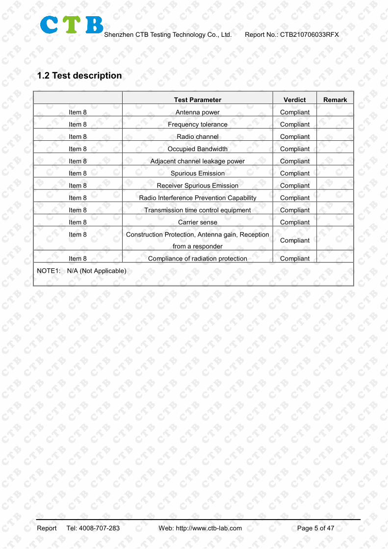
1.2 Test description
Test Parameter Verdict Remark
Item 8 Antenna power Compliant
Item 8 Frequency tolerance Compliant
Item 8 Radio channel Compliant
Item 8 Occupied Bandwidth Compliant
Item 8 Adjacent channel leakage power Compliant
Item 8 Spurious Emission Compliant
Item 8 Receiver Spurious Emission Compliant
Item 8 Radio Interference Prevention Capability Compliant
Item 8 Transmission time control equipment Compliant
Item 8 Carrier sense Compliant
Item 8 Construction Protection, Antenna gain, Reception
from a responder Compliant
Item 8 Compliance of radiation protection Compliant
NOTE1: N/A (Not Applicable)
Report Tel: 4008-707-283 Web: http://www.ctb-lab.com Page 5 of 47

Shenzhen CTB Testing Technology Co., Ltd. Report No.: CTB210706033RFX
1.3 Measurement uncertainty
The reported uncertainty of measurement y ±U, where expended uncertainty U is based on a standard uncertainty multiplied by a coverage factor of k=2, providing a level of confidence of approximately 95 %.
Item Uncertainty Occupancy bandwidth 54.3kHz Conducted output power Above 1G 0.9dB Conducted output power below 1G 0.9dB Power Spectral Density , Conduction 0.9dB Conduction spurious emissions 2.0dB Out of band emission 2.0dB 3m camber Radiated spurious emission(30MHz-1GHz)
4.6dB
3m chamber Radiated spurious emission(1GHz-18GHz)
5.1dB
3m chamber Radiated spurious emission(18GHz-40GHz)
3.4dB
Frequency Error 54.3Hz Adjacent channel powerbelow 1G 2.6dB Adjacent channel powerAbove 1G 2.8dB humidity uncertainty 5.5% Temperature uncertainty 0.63℃
frequency 1×10⁻⁷
Report Tel: 4008-707-283 Web: http://www.ctb-lab.com Page 6 of 47

Shenzhen CTB Testing Technology Co., Ltd. Report No.: CTB210706033RFX 2. GENERAL INFORMATION 2.1 General description of EUT
Model(s): AT907
Model Description: N/A
Hardware Version: V1.0
Software Version: V1.0
Operation Frequency: 916.8-919.2MHz
Rated output power: 10mW
Type of Modulation: ASK
Antenna installation: External antenna
Antenna Gain: 1dBi Ratings: DC 5.0V charging from adapter
DC3.8V from battery
Note: For more detailed features description, please refer to the manufacturer’s specifications or the User's Manual.
Report Tel: 4008-707-283 Web: http://www.ctb-lab.com Page 7 of 47

Shenzhen CTB Testing Technology Co., Ltd. Report No.: CTB210706033RFX 2.2 Description of test modes The EUT has been tested under typical operating condition. The Applicant provides communication tools software to control the EUT for staying in continuous transmitting and receiving mode for testing.
Unit radio channel number Frequency (MHz) Unit radio channel number Frequency
(MHz) 5 916.8
11 918.0 17 919.2
Note: Test performed at the lowest/middle/highest frequencies selected in the list above for EUT
supported while working on specified mode.
PretestMode Description
Transmitting mode Low channel: 916.8MHz
Middle channel: 918.0MHz High channel: 919.2MHz
Receiver mode Low channel: 916.8MHz Middle channel: 918.0MHz High channel: 919.2MHz
Report Tel: 4008-707-283 Web: http://www.ctb-lab.com Page 8 of 47

Shenzhen CTB Testing Technology Co., Ltd. Report No.: CTB210706033RFX 2.3 Environmental conditions
During the measurement the environmental conditions were within the listed ranges: Supply Voltage supply power V Rated module power V Tolerance
(%) Normal 3.8 3.3 +10% 4.2 3.3 0 -10% 3.4 3.3 0 Others Temperature (°C) 20-25 Relative humidity 51 %. ATM Pressure: 1019 mbar Note 1: When the input voltage is reduced or increased by 10%, the regulator voltage changes of less than 1%. So the following test items are conducted in the normal voltage.
Report Tel: 4008-707-283 Web: http://www.ctb-lab.com Page 9 of 47

Shenzhen CTB Testing Technology Co., Ltd. Report No.: CTB210706033RFX
2.4 Block diagram showing the configuration of system tested
Mode 1:
2.5 Description of support units (conducted mode) The EUT has been tested as an independent unit together with other necessary accessories or support units. The following support units or accessories were used to form a representative test configuration during the tests.
Item Equipment Mfr/Brand Model/TypeNo. Note
E-1 Handheld reader N/A AT907 EUT
Item ShieldedTyp
FerriteCore Length Note
Note: (1) The support equipment was authorized by Declaration ofConfirmation. (2) For detachable type I/O cable should be specified the length in cmin(Length)
column. (3) “YES” is means “shielded” “with core”; “NO” is means “unshielded” “withoutcore”.
EUT
Report Tel: 4008-707-283 Web: http://www.ctb-lab.com Page 10 of 47

Shenzhen CTB Testing Technology Co., Ltd. Report No.: CTB210706033RFX 2.6 Measurement equipment list Item Equipment Manufacturer Type No. Serial No. Last calibration Calibrated until
1 Spectrum Analyzer
Agilent N9020A MY52090073 Oct. 17, 2020 Oct. 16, 2021
2 Power Sensor Agilent U2021XA MY56120032 Nov. 02, 2020 Nov. 01, 2021
3 Power Sensor Agilent U2021XA MY56120034 Nov. 02, 2020 Nov. 01, 2021
4 Communication
test set R&S CMW500 118735 Nov. 02, 2020 Nov. 01, 2021
5 Spectrum Analyzer
R&S FSP40 100550 Nov. 02, 2020 Nov. 01, 2021
6 Signal
Generator Agilent N5181A MY49060920 Nov. 02, 2020 Nov. 01, 2021
7 Signal
Generator Agilent N5182A MY47420195 Nov. 02, 2020 Nov. 01, 2021
8 Communication
test set R&S CMU200 119978 Nov. 02, 2020 Nov. 01, 2021
9 band rejection
filter Shenxiang
MSF2400-2483.5MS-1154
20181015001 Nov. 02, 2020 Nov. 01, 2021
10 band rejection
filter Shenxiang
MSF5150-5850MS-1155
20181015001 Nov. 02, 2020 Nov. 01, 2021
11 band rejection
filter Xingbo
XBLBQ-DZA120
190821-1-1 Nov. 02, 2020 Nov. 01, 2021
12 BT&WI-FI
Automatic test software
Micowave MTS8310 Ver. 2.0.0.0 \ \
13
Rohde & Schwarz SFU
Broadcast Test System
R&S SFU 101017 Nov. 02, 2020 Nov. 01, 2021
14 Temperature
humidity chamber
Hongjing TH-80CH DG-15174 Nov. 02, 2020 Nov. 01, 2021
15 234G Automatic
test software Micowave MTS8200 Ver. 2.0.0.0 \ \
16 966 chamber C.R.T. 966 Room 966 Nov. 02, 2020 Nov. 01, 2021
Report Tel: 4008-707-283 Web: http://www.ctb-lab.com Page 11 of 47

Shenzhen CTB Testing Technology Co., Ltd. Report No.: CTB210706033RFX
17 Receiver R&S ESPI 100362 Nov. 02, 2020 Nov. 01, 2021
18 Amplifier HP 8447E 2945A02747 Nov. 02, 2020 Nov. 01, 2021
19 Amplifier Agilent 8449B 3008A01838 Nov. 02, 2020 Nov. 01, 2021
20 TRILOG
Broadband Antenna
Schwarzbeck VULB 9163 869 Nov. 02, 2020 Nov. 01, 2021
21 Horn Antenna Schwarzbeck BBHA9120D 1911 Nov. 02, 2020 Nov. 01, 2021
22 Software Fala EZ-EMC FA-03A2 RE \ \ 23 3-Loop Antenna Daze ZN30401 17014 Nov. 02, 2020 Nov. 01, 2021 24 loop antenna ZHINAN ZN30900A / Nov. 02, 2020 Nov. 01, 2021
25 Horn antenna A/H/System SAS-574 588 Nov. 02, 2020 Nov. 01, 2021
26 Amplifier AEROFLEX / S/N/ 097 Nov. 02, 2020 Nov. 01, 2021
Report Tel: 4008-707-283 Web: http://www.ctb-lab.com Page 12 of 47

Shenzhen CTB Testing Technology Co., Ltd. Report No.: CTB210706033RFX
3. TEST CONDITIONS AND RESULTS 3.1 Frequency error 3.1.1 Limit
Item Limits
Frequency Error +/-20ppm 3.1.2 Test configuration 3.1.3 Test procedure The EUT was directly connected to the spectrum analyzer and antenna output port as show in the block diagram as TEST CONFIGURATION shows. EUT Condition: non-modulation Spectrum Condition:
Frequency: test frequency Span: 500 kHz RBW: 3KHz VBW: 3KHz Sweep time: Auto Detector mode: Positive peak Indication mode: max hold
EUT Dummy load (Attenuator)
Spectrum
Report Tel: 4008-707-283 Web: http://www.ctb-lab.com Page 13 of 47

Shenzhen CTB Testing Technology Co., Ltd. Report No.: CTB210706033RFX 3.1.4 Test results
Test voltage (V)
Frequency (MHz)
Read (MHz)
Deviation (MHz)
Tolerance (ppm)
Limit (ppm)
Result
Normal Voltage
916.8 916.800 0.000 0.000
+/-20.00 Pass 918.0 918.000 0.000 0.000
919.2 919.200 0.000 0.000
Report Tel: 4008-707-283 Web: http://www.ctb-lab.com Page 14 of 47

Shenzhen CTB Testing Technology Co., Ltd. Report No.: CTB210706033RFX
Normal Voltage
916.8MHz 918.0MHz
919.2MHz
Report Tel: 4008-707-283 Web: http://www.ctb-lab.com Page 15 of 47
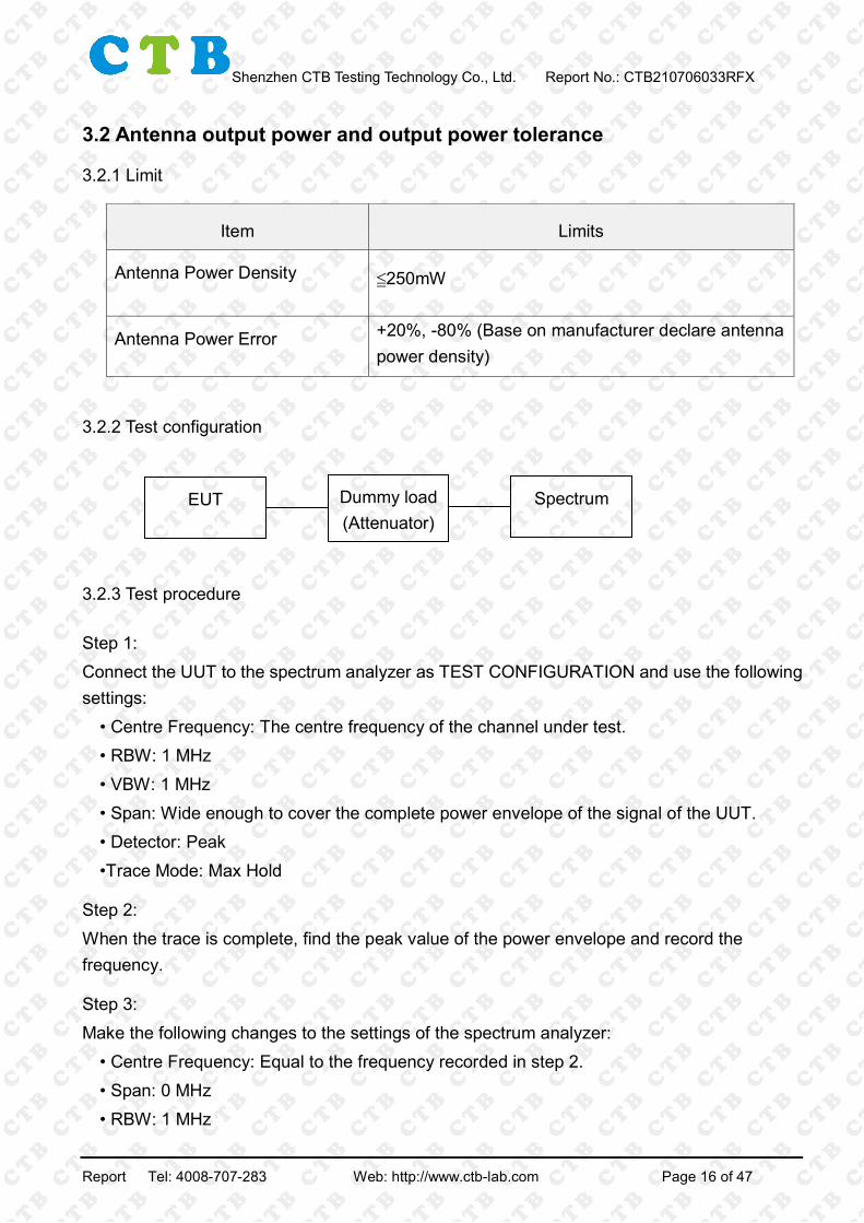
Shenzhen CTB Testing Technology Co., Ltd. Report No.: CTB210706033RFX 3.2 Antenna output power and output power tolerance 3.2.1 Limit
Item Limits
Antenna Power Density ≦250mW
Antenna Power Error +20%, -80% (Base on manufacturer declare antenna power density)
3.2.2 Test configuration 3.2.3 Test procedure Step 1: Connect the UUT to the spectrum analyzer as TEST CONFIGURATION and use the following settings:
• Centre Frequency: The centre frequency of the channel under test. • RBW: 1 MHz • VBW: 1 MHz • Span: Wide enough to cover the complete power envelope of the signal of the UUT. • Detector: Peak •Trace Mode: Max Hold
Step 2: When the trace is complete, find the peak value of the power envelope and record the frequency.
Step 3: Make the following changes to the settings of the spectrum analyzer:
• Centre Frequency: Equal to the frequency recorded in step 2. • Span: 0 MHz • RBW: 1 MHz
EUT Dummy load (Attenuator)
Spectrum
Report Tel: 4008-707-283 Web: http://www.ctb-lab.com Page 16 of 47

Shenzhen CTB Testing Technology Co., Ltd. Report No.: CTB210706033RFX
• VBW: 1 MHz • Detector: RMS • Trace Mode: Max Hold
3.2.4 Test results
Test
modulation
Test
Channel
Average
burst
power(dBm)
Output
power
(mW)
Rated output
power (mW)
Tolerance
(%) Limit Result
ASK
L 8.740 7.482 10 -25.18
250mW
-80%~20% Pass
M 8.898 7.759 10 -22.41
250mW
-80%~20% Pass
H 8.537 7.140 10 -28.60
250mW
-80%~20% Pass
Test
voltage (V) Mode Channel Polar
EIRP
(dBm)
Limit
(dBm)
Normal
Voltage ASK
L H 9.589
27
M H 9.368
H H 9.111
L V 9.548
M V 9.453
H V 9.897
Report Tel: 4008-707-283 Web: http://www.ctb-lab.com Page 17 of 47

Shenzhen CTB Testing Technology Co., Ltd. Report No.: CTB210706033RFX 3.3 Occupied bandwidth and spreading bandwidth
3.3.1 Limit
Item Limits
Occupied Band Width: ≤200KHz;
3.3.2 Test configuration 3.3.3 Test procedure 1. Setting of SA is following as fellow:
RBW: Less than 3% of the allowable value specified in Equipment Regulations VBW: Comparable to the resolution bandwidth Sweep time: Auto Sweep Mode: Continuous sweep Detect mode: Positive peak Trace mode: Max hold
2. EUT have transmitted the maximum modulation signal and fixed channelize. SA set to 99% of occupied bandwidth to measure occupied bandwidth.
EUT Dummy load (Attenuator)
Spectrum
Report Tel: 4008-707-283 Web: http://www.ctb-lab.com Page 18 of 47

Shenzhen CTB Testing Technology Co., Ltd. Report No.: CTB210706033RFX 3.3.4 Test results
Test modulation
Test Channel
Occupy 99% Bandwidth
(KHz)
Limit (MHz)
Result
ASK
L 141.87
≤200KHz Pass M 143.24
H 144.66
99% Bandwidth
Test condition:
L M
H
Report Tel: 4008-707-283 Web: http://www.ctb-lab.com Page 19 of 47

Shenzhen CTB Testing Technology Co., Ltd. Report No.: CTB210706033RFX
3.4 Unwanted emission strength
3.4.1 Limit
3.4.2 Test configuration 3.4.3 Test procedure Spectrum analyzer set at the time of measurement of firing sub is as follows. Center frequency Firing frequency side Span From 30MHz to 10GHz RBW From 945MHz up to 1GHz and if, 100kHz from 30MHz to 710MHz From 1GHz to 10GHz and if, 1MHz to 945MHz from 710MHz VBW Equal to RBW Y-axis scale 10dB/Div Sweep time the minimum time is guaranteed measurement accuracy Sweep mode Signal sweep Detection mode Sample
(1) Set as 2 ⑴ spectrum analyzer, to explore the maximum value of the amplitude of the
EUT Dummy load (Attenuator)
Spectrum
Report Tel: 4008-707-283 Web: http://www.ctb-lab.com Page 20 of 47
Shenzhen CTB Testing Technology Co., Ltd. Report No.: CTB210706033RFX
firing side to sweep up to 10GHz from 30MHz. (2) If the allowable value is the value that you search the Regulations equipment, the measured values and the values that you search. (3) If you exceed the allowable value is the value that you search the Regulations facilities,
asking the frequency of side-firing, set as 2 ⑵ spectrum analyzer to measure the average
power averaging processing is performed. (4) If you cannot set the state of the receive-only facilities receiving radio to use the antenna
that are common in the measurement of up to ⑶, external trigger signal spectrum analyzer
using a broadband detector the transmission power of the test equipment from ⑴
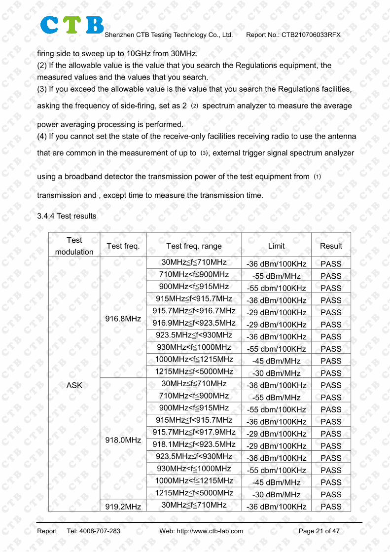
transmission and , except time to measure the transmission time. 3.4.4 Test results
Test modulation
Test freq. Test freq. range Limit Result
ASK
916.8MHz
30MHz≦f≦710MHz -36 dBm/100KHz PASS 710MHz<f≦900MHz -55 dBm/MHz PASS 900MHz<f≦915MHz -55 dbm/100KHz PASS
915MHz≦f<915.7MHz -36 dBm/100KHz PASS 915.7MHz≦f<916.7MHz -29 dBm/100KHz PASS 916.9MHz≦f<923.5MHz -29 dBm/100KHz PASS 923.5MHz≦f<930MHz -36 dBm/100KHz PASS 930MHz<f≦1000MHz -55 dbm/100KHz PASS 1000MHz<f≦1215MHz -45 dBm/MHz PASS 1215MHz≦f<5000MHz -30 dBm/MHz PASS
918.0MHz
30MHz≦f≦710MHz -36 dBm/100KHz PASS 710MHz<f≦900MHz -55 dBm/MHz PASS 900MHz<f≦915MHz -55 dbm/100KHz PASS
915MHz≦f<915.7MHz -36 dBm/100KHz PASS 915.7MHz≦f<917.9MHz -29 dBm/100KHz PASS 918.1MHz≦f<923.5MHz -29 dBm/100KHz PASS 923.5MHz≦f<930MHz -36 dBm/100KHz PASS 930MHz<f≦1000MHz -55 dbm/100KHz PASS 1000MHz<f≦1215MHz -45 dBm/MHz PASS 1215MHz≦f<5000MHz -30 dBm/MHz PASS
919.2MHz 30MHz≦f≦710MHz -36 dBm/100KHz PASS
Report Tel: 4008-707-283 Web: http://www.ctb-lab.com Page 21 of 47

Shenzhen CTB Testing Technology Co., Ltd. Report No.: CTB210706033RFX
710MHz<f≦900MHz -55 dBm/MHz PASS 900MHz<f≦915MHz -55 dbm/100KHz PASS
915MHz≦f<915.7MHz -36 dBm/100KHz PASS 915.7MHz≦f<919.1MHz -29 dBm/100KHz PASS 919.3MHz≦f<923.5MHz -29 dBm/100KHz PASS 923.5MHz≦f<930MHz -36 dBm/100KHz PASS 930MHz<f≦1000MHz -55 dbm/100KHz PASS 1000MHz<f≦1215MHz -45 dBm/MHz PASS 1215MHz≦f<5000MHz -30 dBm/MHz PASS
Test channel: 916.8MHz
30MHz≦f≦710MHz 710MHz<f≦900MHz
900MHz<f≦915MHz 915MHz≦f<915.7MHz
Report Tel: 4008-707-283 Web: http://www.ctb-lab.com Page 22 of 47

Shenzhen CTB Testing Technology Co., Ltd. Report No.: CTB210706033RFX
915.7MHz<f≦916.6MHz 917.0MHz<f≦923.5MHz
923.5MHz≦f<930MHz 930MHz<f≦1000MHz
1000MHz<f≦1215MHz 1215MHz≦f<12500MHz
Report Tel: 4008-707-283 Web: http://www.ctb-lab.com Page 23 of 47

Shenzhen CTB Testing Technology Co., Ltd. Report No.: CTB210706033RFX
Test channel: 920.4MHz
30MHz≦f≦710MHz 710MHz<f≦900MHz
900MHz<f≦915MHz 915MHz≦f<915.7MHz
915.7MHz<f≦920.2MHz 920.6MHz<f≦923.5MHz
Report Tel: 4008-707-283 Web: http://www.ctb-lab.com Page 24 of 47

Shenzhen CTB Testing Technology Co., Ltd. Report No.: CTB210706033RFX
923.5MHz≦f<930MHz 930MHz<f≦1000MHz
1000MHz<f≦1215MHz 1215MHz≦f<12500MHz
Test channel: 923.4MHz
30MHz≦f≦710MHz 710MHz<f≦900MHz
Report Tel: 4008-707-283 Web: http://www.ctb-lab.com Page 25 of 47

Shenzhen CTB Testing Technology Co., Ltd. Report No.: CTB210706033RFX
900MHz<f≦915MHz 915MHz≦f<915.7MHz
915.7MHz<f≦920.6MHz 921.0MHz<f≦923.5MHz
923.5MHz≦f<930MHz 930MHz<f≦1000MHz
Report Tel: 4008-707-283 Web: http://www.ctb-lab.com Page 26 of 47

Shenzhen CTB Testing Technology Co., Ltd. Report No.: CTB210706033RFX
1000MHz<f≦1215MHz 1215MHz≦f<12500MHz
Report Tel: 4008-707-283 Web: http://www.ctb-lab.com Page 27 of 47

Shenzhen CTB Testing Technology Co., Ltd. Report No.: CTB210706033RFX
3.5 ADJACENT CHANNEL LEAKAGE POWER 3.5.1 Limit Frequency band of signal in use is from 916.8MHz to 920.8MHz. (Antenna power is 250mW or less (with carrier
sense).)
Leakage power in unit channel adjacent to a radio channel: It shall be –5dBm or less.
3.5.2 Test configuration
EUT Dummy load (Attenuator)
Spectrum
Report Tel: 4008-707-283 Web: http://www.ctb-lab.com Page 28 of 47

Shenzhen CTB Testing Technology Co., Ltd. Report No.: CTB210706033RFX 3.5.3 Test procedure Spectrum analyzer is set as follows.
Center frequency Carrier frequency
Carrier frequency +100kHz×(n+1)
Carrier frequency -100kHz×(n+1)
Span When measuring the total power (carrier power) : n×200kHz
Adjacent channel leakage power measurement when the upper and lower: 199kHz
Resolution bandwidth 100 KHz
Video bandwidth more than three times the resolution bandwidth
Sweep time the minimum time is guaranteed measurement accuracy (in the case of
wave burst, burst duration of one or more per sample)
Sweep mode Single sweep
Detection mode RMS
n is the number of channel units used at the same time as a radio channel.
If it takes a long time to sweep a long burst period, continuous sweep sweep mode, as Max Hold the display
mode can be measured until there is no variation of the displayed waveform. In this case, it is possible to shorten
the time spectrum analyzer sweep.
Report Tel: 4008-707-283 Web: http://www.ctb-lab.com Page 29 of 47

Shenzhen CTB Testing Technology Co., Ltd. Report No.: CTB210706033RFX
3.5.4 Test results
916.8MHz channel
918.0MHz channel
Report Tel: 4008-707-283 Web: http://www.ctb-lab.com Page 30 of 47

Shenzhen CTB Testing Technology Co., Ltd. Report No.: CTB210706033RFX
919.2MHz channel
Report Tel: 4008-707-283 Web: http://www.ctb-lab.com Page 31 of 47

Shenzhen CTB Testing Technology Co., Ltd. Report No.: CTB210706033RFX 3.6 Secondary radiated emission strength
3.6.1 Limit Permissible Values for Spurious Emission / Unwanted Emission Intensity at the antenna input shall be less than the value in Table 3-16.
3.6.2 Test configuration 3.6.3 Test procedure Spectrum analyzer set at the time of measurement of firing sub is as follows.
Center frequency Firing frequency side
Span From 30MHz to 10GHz
RBW From 945MHz up to 1GHz and if, 100kHz from 30MHz to
710MHz frequency
sweep width
From 1GHz to 10GHz and if, 1MHz to 945MHz from 710MHz
frequency sweep width
VBW Equal to RBW
EUT Dummy load (Attenuator)
Spectrum
Report Tel: 4008-707-283 Web: http://www.ctb-lab.com Page 32 of 47

Shenzhen CTB Testing Technology Co., Ltd. Report No.: CTB210706033RFX
Y-axis scale 10dB/Div
Sweep time the minimum time is guaranteed measurement accuracy
Sweep mode Signal sweep
Detection mode Sample
(1) Set as 2 ⑴ spectrum analyzer, to explore the maximum value of the amplitude of the
firing side to sweep up to 10GHz from 30MHz.
(2) If the allowable value is the value that you search the Regulations equipment, the
measured values and the values that you search.
(3) If you exceed the allowable value is the value that you search the Regulations facilities,
asking the frequency of side-firing, set as 2 ⑵ spectrum analyzer to measure the average
power averaging processing is performed.
(4) If you cannot set the state of the receive-only facilities receiving radio to use the antenna
that are common in the measurement of up to ⑶, external trigger signal spectrum analyzer
using a broadband detector the transmission power of the test equipment from ⑴
transmission and , except time to measure the transmission time.
3.6.4 Test results
Report Tel: 4008-707-283 Web: http://www.ctb-lab.com Page 33 of 47

Shenzhen CTB Testing Technology Co., Ltd. Report No.: CTB210706033RFX
Test
modulation Test freq. Test freq. range Limit Result
ASK
916.8MHz
30MHz≦f≦710MHz -54 dBm/100KHz PASS 710MHz<f≦900MHz -55 dBm/MHz PASS 900MHz<f≦915MHz -55 dbm/100KHz PASS 915MHz≦f<930MHz -54 dBm/100KHz PASS
930MHz<f≦1000MHz -55 dbm/100KHz PASS 1000MHz≦f<12750MHz -47 dBm/MHz PASS
918.0MHz
30MHz≦f≦710MHz -54 dBm/100KHz PASS 710MHz<f≦900MHz -55 dBm/MHz PASS 900MHz<f≦915MHz -55 dbm/100KHz PASS 915MHz≦f<930MHz -54 dBm/100KHz PASS
930MHz<f≦1000MHz -55 dbm/100KHz PASS 1000MHz≦f<12750MHz -47 dBm/MHz PASS
919.2MHz
30MHz≦f≦710MHz -54 dBm/100KHz PASS 710MHz<f≦900MHz -55 dBm/MHz PASS 900MHz<f≦915MHz -55 dbm/100KHz PASS 915MHz≦f<930MHz -54 dBm/100KHz PASS
930MHz<f≦1000MHz -55 dbm/100KHz PASS 1000MHz≦f<12750MHz -47 dBm/MHz PASS
Report Tel: 4008-707-283 Web: http://www.ctb-lab.com Page 34 of 47

Shenzhen CTB Testing Technology Co., Ltd. Report No.: CTB210706033RFX
Test channel: 916.8MHz
30MHz≦f≦710MHz 710MHz<f≦900MHz
900MHz<f≦915MHz 915MHz≦f<930MHz
930MHz<f≦1000MHz 1000MHz<f≦12750MHz
Report Tel: 4008-707-283 Web: http://www.ctb-lab.com Page 35 of 47

Shenzhen CTB Testing Technology Co., Ltd. Report No.: CTB210706033RFX
Test channel: 918.0MHz
30MHz≦f≦710MHz 710MHz<f≦900MHz
900MHz<f≦915MHz 915MHz≦f<930MHz
930MHz<f≦1000MHz 1000MHz<f≦12750MHz
Report Tel: 4008-707-283 Web: http://www.ctb-lab.com Page 36 of 47

Shenzhen CTB Testing Technology Co., Ltd. Report No.: CTB210706033RFX
Test channel: 919.2MHz
30MHz≦f≦710MHz 710MHz<f≦900MHz
900MHz<f≦915MHz 915MHz≦f<930MHz
930MHz<f≦1000MHz 1000MHz<f≦12750MHz
Report Tel: 4008-707-283 Web: http://www.ctb-lab.com Page 37 of 47

Shenzhen CTB Testing Technology Co., Ltd. Report No.: CTB210706033RFX 3.7 TRANSMISSION TIME CONTROL EQUIPMENT
3.7.1 LIMIT (1) In case the 5ms or more carrier sense is required: If the center frequency is from 916.0MHz to 928.0MHz, radio equipment shall stop its transmission of radio wave less than 4s after it starts to emit radio wave. It shall wait 50ms or more for the consecutive transmission. Meanwhile, it may emit radio wave again without waiting 50ms, if the transmission time is less than 4s after its first transmission, and this re-transmission is started after 128μs or more carrier sense, and is finished less than 4s after its first transmission.
3.7.2 Test Setup Block Diagram
3.7.3 TEST PROCEDURES Setting the spectrum analyzer is as follows. Center frequency Test frequency Span 0Hz RBW 1MHz VBW Equal to RBW Sweep time Approximately twice the value of equipment acceptable to the Regulations Detection mode Positive peak Triggering condition Level rise
1) As two sets of spectrum analyzer, set to trigger at rising edge trigger conditions, to launch
state radio test equipment.
2) To verify that, and stopped firing of radio equipment within the time prescribed in the
regulations, downtime is greater than or equal to time transmitting equipment to the
Regulations.
3) If there is not enough time resolution of the spectrum analyzer in the measurement of the
transmission pause time, set the trigger down to shorten the time to sweep up the trigger
conditions, the time after stopping the firing of test equipment radio equipment prescribed
in the regulations ensure that the time is greater than or equal to.
EUT Dummy load (Attenuator)
Spectrum
Report Tel: 4008-707-283 Web: http://www.ctb-lab.com Page 38 of 47

Shenzhen CTB Testing Technology Co., Ltd. Report No.: CTB210706033RFX
3.7.4 TEST RESULT
Test Item Carrier sense time Sending duration Pause duration
Limit 5ms or more 4s or less 50ms or more
Test Result >5ms 1.340 13.36s
Test Result: Pass
Report Tel: 4008-707-283 Web: http://www.ctb-lab.com Page 39 of 47

Shenzhen CTB Testing Technology Co., Ltd. Report No.: CTB210706033RFX
Report Tel: 4008-707-283 Web: http://www.ctb-lab.com Page 40 of 47

Shenzhen CTB Testing Technology Co., Ltd. Report No.: CTB210706033RFX
3.8 CARRIER SENSE 3.8.1 Limit According to STD-T106, 3.2.3 (2) Carrier sense (ORE: article 49, NT: No.407, 2008) Controller shall have functions that comply with the conditions A, B and C A. Carrier sense level When the amount of the received power at the antenna input is -74 dBm or more, the controller shall prohibit transmission of radio wave in the same channel of the received power. B. Bandwidth of carrier sense The receiving bandwidth for carrier sense shall be the same bandwidth of its transmitting radio channel. In this regulation, emission shall be prohibited when the carrier sense level on the intended radio channel is more than -74dBm(200 kHz x n) at the antenna input. (Note: n is the number of the unit radio channels used Carrier sense time C. Time duration shall be more than 5 ms to detect whether the intended radio channel is open or not. In this regulation, time duration is calculated as follows: Time 5 + (R x 0.5) ms, where R is a random integer from 0 to 10. 3.8.2 Test Setup Block Diagram
3.8.3 Test Procedure 1. SG adjust the frequency as same as the EUT transmitted signal, unmodulation, power level 0dBm, Then turn off the RF signal. 2. EUT have transmitted the maximum modulation signal and fixed channel 3. Setting of the SA following as RBW/VBW: 1/3MHz SPAN: 50MHz Sweep time: Auto continue PK 4. SG Signal -74dBm(Bandwide=200kHz) to EUT, EUT prohibit transmission 5. And SG Signal -80dBm(Bandwide=200kHz) to EUT, EUT prohibit transmission(Frequencies within 920.5MHz or more and 923.5MHz or less STD-108)
Report Tel: 4008-707-283 Web: http://www.ctb-lab.com Page 41 of 47

Shenzhen CTB Testing Technology Co., Ltd. Report No.: CTB210706033RFX
3.8.4Test results
For Require (Level -74dBm)
Test Condition Frequency(MHz) Transmitting Power(dBm)
Normal Operating 916.8 7.04
Inject CW(-74dBm,
200kHz Bandwidth) 916.8
-67.22dBm(Base noise, Stop
transmission)
Stop Inject CW 916.8 7.87
Test Condition Frequency(MHz) Transmitting Power(dBm)
Normal Operating 920.2 7.054
Inject CW(-80dBm,
200kHz Bandwidth) 920.2
-68.63dBm(Base noise, Stop
transmission)
Stop Inject CW 920.2 7.048
Test Result: Pass
Report Tel: 4008-707-283 Web: http://www.ctb-lab.com Page 42 of 47

Shenzhen CTB Testing Technology Co., Ltd. Report No.: CTB210706033RFX
3.9 Radio Channel
3.9.1 limit
Unit channel: 916.8-919.2MHz (200 KHz interval), 200KHz BW
Simultaneous use channels:MAX 3
3.9.2 Test results
Pass
N=1, Frequency allocation 916.8, 918.0, 912.2
Report Tel: 4008-707-283 Web: http://www.ctb-lab.com Page 43 of 47

Shenzhen CTB Testing Technology Co., Ltd. Report No.: CTB210706033RFX
3.10 Construction Protection, Antenna gain, Reception from a responder
3.4 Antenna
Antenna gain 6 dBi or less (absolute gain)
Provided that measured EIRP (Equivalent Isotropically Radiated Power) is less than the value of 6dBi plus 1W of antenna power, it is allowed to fill in the gap by the antenna gain.
-Antenna gain=4.0dBi<6dBi
Reception from a responder
Receiver can receive a radio wave from a responder.
Report Tel: 4008-707-283 Web: http://www.ctb-lab.com Page 44 of 47

Shenzhen CTB Testing Technology Co., Ltd. Report No.: CTB210706033RFX 3.11 RF SHIELDINGMETHOD
We apply the product for Japan RF certification. The high-frequency section and modulation section of the radio equipment except for the antenna system shall not be capable of being opened easily.
Confirmation method
Sealed with special screws. Plastic chassis is being welded using ultrasonic wavs. Chassis is glued using a special adhesive. Metal covers are spot-fused. Cover is specially interlocked. RF and Modulation components are covered with shielding case and this shielding case
is soldered. Shield case is welded ant RF and modulations parts, and ID-ROM is welded using BGA
Method. Shield case is welded ant RF and modulations parts, and ID-ROM is glued at its lead with
a special adhesive. Shield case is welded ant RF and modulations parts, and ID-ROM is glued with a
non-transparent laminating agent. Other: All RF and modulation section packet in one IC, and IC is welded using SMT
Method, and RF module is welded on the main board, end-User can’t open it easily.
1
Report Tel: 4008-707-283 Web: http://www.ctb-lab.com Page 45 of 47

Shenzhen CTB Testing Technology Co., Ltd. Report No.: CTB210706033RFX
3.12 Compliance of radiation protection
3.12.1 LIMIT According to Chapter 4 Compliance of radiation protection Signal intensity means electric field strength, power flux density and magnetic field strength (hereinafter the same)..It is set forth as that the place at which the signal intensity coming from radio equipment exceeds the value shown in table 4-1, protection facilities are required to guard person who are there except for operator.
3.12.2 TEST RESULT
Manufacturer declare the distance is at least 50cm to other person, test period 6min
Electric field strength Test Position Measure Value (V/m) Limit(V/m) Test Result Antenna Front Side
3.577 48.09
Compliance
Magnetic field strength Test Position Measure Value (A/m) Limit(A/m) Test Result Antenna Front Side
0.083 0.13 Compliance
Power Flux density Test Position Power flux density (mW/cm2) Limit(mW/cm2) Test Result Antenna Front Side
0.083 0.6136 Compliance
Limit(V/m)=1.585*f1/2=1.585*920.41/2=48.09; Limit(A/m)=f1/2/237.8=920.4/2/237.8=0.13 Limit(mW/cm2)=f/1500=920.4/1500=0.6136
Report Tel: 4008-707-283 Web: http://www.ctb-lab.com Page 46 of 47
Shenzhen CTB Testing Technology Co., Ltd. Report No.: CTB210706033RFX
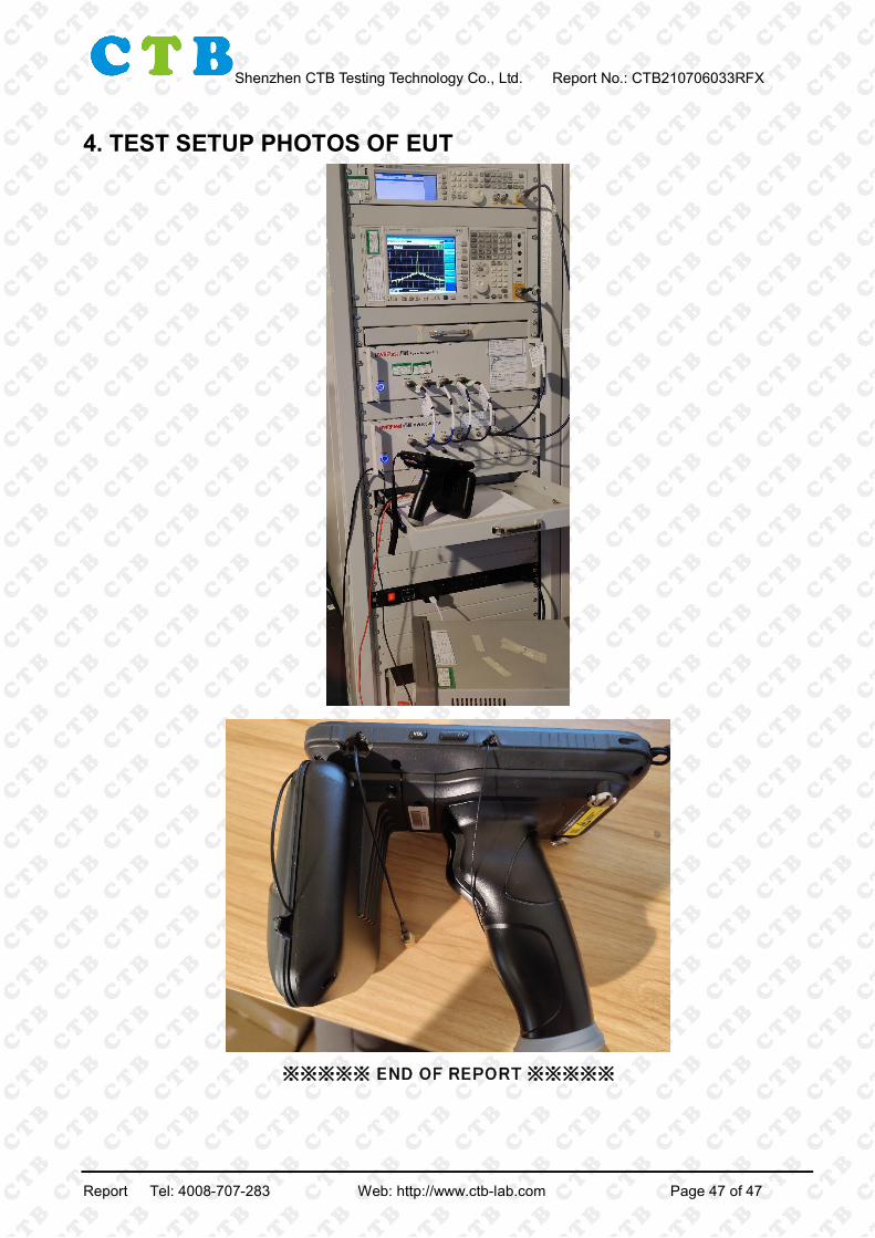
4. TEST SETUP PHOTOS OF EUT
※※※※※ END OF REPORT ※※※※※
Report Tel: 4008-707-283 Web: http://www.ctb-lab.com Page 47 of 47