shell fluid
DESCRIPTION
Shell fluid interactionTRANSCRIPT

Int. J . mech. Sei. Pergamon Press. 1969. Vol. 11, pp. 767-779. Pr in ted in Great Bri tain
VIBRATIONS OF ORTHOTROPIC SANDWICH CONICAL SHELLS WITH F R E E EDGES*
CHARLES W. BERT a n d JOHN D. RAY t University of Oklahoma, Norman, Oklahoma
(Received 17 March 1969)
Summary--Experimental and analytical evaluations are presented for the vibrational characteristics of a t runcated conical shell of sandwich construction. The shell consists of fiber glass-epoxy facings and aluminum honeycomb core. The shell is suspended by soft cords, to closely approximate free-free boundary conditions, and excited laterally by an electrodynamic shaker placed at various locations. The Kennedy-Pancu method of data reduction is used to accurately separate vibrational modes having closely spaced frequencies. The two lowest unsymmetric-mode frequencies, for various values of circumferential wave number, agree quite closely with those predicted by a Rayleigh-Ritz inextensional analysis which includes the orthotropic nature of the composite material facings.
A , B cit, d~t
Do Dso
Es, Eo
Gso h
m
n
P,Q, R RI, R2
8
81 , 8 2
t tl
U, V, W
V, W
c~
EbO
~bo 0 ff
N O T A T I O N
constants of integration appearing in equation (2) parameters defined by equations (7) shell flexural rigidity in circumferential direction; see equation (8) shell twisting rigidity; see equation (9) Young's moduli of facing material in meridional and circumferential directions, respectively, psi shear modulus of facings in sO plane, psi distance between centroids of the facings, in. designation of general modes circumferential wave number parameters defined by equations (6) radii of small and large ends of shell, respectively, in. distance along meridian of middle surface of conical shell, measured from apex, in. values of s at small and large ends of shell, respectively time, sec thickness of one facing, in. meridional, circumferential and normal displacements, respectively, in. normalized circumferential and normal displacements, given by equations (1 O) and (11) semi-vertex angle of cone, degree completeness parameter = R1/R 2 circumferential bending strain, dimensionless normalized value of ebO, defined by equation (13), dimensionless circumferential angular co-ordinate, degree change in curvature in circumferential direction, in-1
* This work is a part of research sponsored by the U.S. Army Aviation Materiel Laboratories, Fort Eustis, Virginia, with James P. Waller as technical monitor. The assistance of W. C. Crisman in fabricating the shell and of B. L. Mayberry in instrumentat ion is gratefully acknowledged.
t Presently at Memphis State University, Memphis, Tennessee. 767

768 CHARLES W. BERT a n d JOHN D. RAY
e igenva lue ; see e q u a t i o n (4) vao, vos Poisson ' s r a t ios of t he fac ing ma te r i a l , d imens ion less
v Po i sson ' s r a t io of i so t ropic ma te r i a l , d imens ion less p m a t e r i a l dens i ty , lb-see~/in 4
co f requency , rad . / sec toe, co i n a t u r a l f requencies assoc ia ted w i t h p u r e l y ex tens iona l m o t i o n a n d w i t h
pu re ly i nex tens iona l mo t ion , respec t ive ly , rad . /sec
1. INTRODUCTION
THE OBJECTIVES of the present paper were (I) to measure resonant frequencies and associated modal strain distributions of a truncated conical sandwich shell suspended in the free-free condition and (2) to compare these quantities with theoretical predictions.
A number of experimental investigations have been carried out to evaluate theories of vibration of sandwich-type beams and plates. 1 However, the authors do not know of any investigation on sandwich-type shell structures which are widely used in aircraft structures. The shell configuration used in the present investigation was that of a truncated cone. The scale selected was sufficiently large to be typical of an aircraft fuselage and to achieve resonant frequencies sufficiently low to enable accurate measurement of a large number of natural modes. Also, it is difficult to scale down a sandwich-type structure, i.e. if the core thickness is too thin, the sandwich effect is negligible.
To be quite certain that the boundary conditions achieved in the experi- ments matched those used in analysis, the boundary conditions selected for the experiments were free edges. Also, these conditions were the least expensive to achieve experimentally and were used in previous experiments on homo- geneous shells. ~ 6
Although the free-free condition is most easily achieved experimentally, it is perhaps the most difficult condition from an analytical viewpoint, particularly in the ease of a sandwich shell, because of the difficulty in finding functions that satisfy the boundary conditions. This is attested to by the very limited number of analyses of homogeneous conical shells (or even homogeneous cylindrical shells) with these boundary conditions. The analysis presented here can be applied to truncated conical shells of either simple single-layer or sandwich construction with either isotropic or orthotropic (composite-material) facings. Inextensional motion, in which the middle-surface extensional strains and transverse shear strains are neglected, is assumed. Solution is carried out by the Rayleigh-Ritz energy method for the two inextensional modes, which are the lowest unsymmetric modes. The circumferential wave number, n, may be any integer greater than one. The validity of the simplifying assumptions made in the analysis are verified by the good agreement between the experi- mental and analytical results.
2. S P E C I M E N S A N D M A T E R I A L
Tab le 1 gives d a t a on t h e s andwich cons t i t uen t s , Tab le 2 l ists t he d imens iona l a n d weight charac te r i s t i c s of t he shell, a n d Tab le 3 t a b u l a t e s the m a t e r i a l p roper t i e s of t h e facings a n d core. T he fac ing tens i le p roper t i e s a n d shea r m o d u l u s were d e t e r m i n e d f rom tes t s on smal l tensi le a n d t o r s i o n - t u b e specimens , wh ich were sub jec t to t he same cur ing cycle as t he fac ing l amina te s .

V i b r a t i o n s of o r t h o t r o p i c s andwich conical shells w i t h free edges
TABLE 1. SANDWICH CONSTITUENTS
769
C o n s t i t u e n t Desc r ip t ion Th ickness O r i e n t a t i o n
F a c i n g 828-Z epoxy , Two-p ly W a r p para l le l t o 181-E Vo lan A (0.02 in. shell axis f iber glass to ta l )
Core 5052 A l u m i n u m , 0.3 in. R i b b o n d i rec t ion 1-mil n o n p e r f o r a t e d para l le l to shell foil, 1/4 in. axis h e x a g o n a l cell
Adhes ive AF- 110B film- 0.015 in. s u p p o r t e d epoxy
T A B L E 2. F I N A L SANDWICH SHELL DIMENSIONS AND W E I G H T
R a d i u s to midd le of cross-sect ion (small end) , R 1 22.45 in. R a d i u s to midd le of cross-sect ion (large end) , R 2 28.86 in. Axia l l e n g t h 72.2 in. Conical h a l f ang le 5.06 ° N o m i n a l surface a rea of shell 11,680 in s To ta l we igh t of shell 55 lb
TABLE 3. SHELL-CONSTITUENT MECHANICAL PROPERTIES
A. Fac ings (average t e s t da t a )
I n i t i a l t en s i on modulus , para l le l to wa rp In i t i a l t en s i on modulus , p e r p e n d i c u l a r to wa rp I n i t i a l Po i s son ' s ra t io , load ing para l le l to wa rp In i t i a l Po i s son ' s ra t io , load ing p e r p e n d i c u l a r to wa rp In i t i a l shea r modu lus , shea r ing p l a n e
p e r p e n d i c u l a r to w a r p
E , = 3-64 x 10 e psi Eo = 3.64 x 10 e psi v,o = 0.20 vo8 = 0"20
G,e = 1.33 x 10⁶ psi
B. Core:
Shea r modu lus , para l le l to r i b b o n d i rec t ion 0.0320 x 10 e psi Shea r modu lus , p e r p e n d i c u l a r to r i b b o n d i rec t ion 0.0183 x 10⁶ psi
3. E X P E R I M E N T A L E Q U I P M E N T
T h e shel ls were s u s p e n d e d f r o m a large s teel f r a m e b y six sof t sp r ings {Fig. 1) so t h a t t h e suspens ion r e s o n a n t f r e q u e n c y was be low 1 cps. A n e l e c t r o d y n a m i c exc i te r (MB Model C l l , 50 lb m a x i m u m force capac i ty ) was a t t a c h e d to t h e shell b y a force l ink t h a t was des igned to r educe t h e coupl ing b e t w e e n t h e spec imen a n d t he s teel f rame. T h e exc i t e r was a t t a c h e d a t d i f fe rent loca t ions a r o u n d t h e shell a n d a long t h e l e n g t h to d e t e r m i n e t h e exc i t e r effects on t h e d a t a . A n acee le romete r (Endevco , Model FA-72) was a t t a c h e d to t h e a r m a t u r e of t he exc i t e r to p rov ide a m e a s u r e m e n t of t he e x c i t a t i o n app l i ed to t h e shell.

770 CHARLES W. BERT and JOHN D. RAY
The i n s t r u m e n t a t i o n t r a n s d u c e r s used to m e a s u r e t he s t r a i n d i s t r i b u t i o n a t t he r e s o n a n t f requencies were 600 metal l ic-foi l s t r a i n gages (Budd Model C6-141B) loca ted on t he ou t e r fac ing of t he shell in a n a r r a y as s h o w n on Fig. 2. Two gages were loca ted a t each gr id po in t , one to m eas u r e c i r cumferen t i a l s t r a i n a n d one to measu re mer id iona l s t ra in . The assoc ia ted e lec t ronic ins tmm~enta t ion is s h o w n on t he p h o t o g r a p h in Fig. 1.
\ \ \ \ i l l I I I l l I
~ \ l i l l l l l l l l!!!!!!
\ \ \ \ \ \ i ~ i l l l \ \ \ \ l l l l l l l l \ \ \ \ \ \ l ~ l I I i
\ \ \ \ l l l i l l l l
, , ' / / / / / / / / / / / iofl j l / / I l l l l l l Iol ] I I t I I I I I I I I I I l l l / / / / / / Iol I I I I I f I I I I I I I / / /
I I I l l t l l l l /
II I t l /11I / / / / / / / / / \ \ \ \ I \ I I I I I I P J I I I I I I ~ I I I / I / / / J
o EXCITER LOCATIONS
FIG. 2. L a y o u t of shell showing s t ra in -gage locat ions . A t each in te r io r in te rsec t ion , t he re are two gages, one mer id iona l a n d one c i rcumferent ia l .
The o u t p u t s of t h e s t r a in -gage s y s t e m a n d t he acce le romete r were app l ied to each side of t h e digi ta l phase m e t e r ( A D - Y U Digi ta l P h a s e Meter , Model 524A a n d E A I Dig i ta l Vo l tme te r , Model 5002A), wh ich i nd i ca t ed t h e r e l a t ive phase b e t w e e n t he i n p u t a n d s t r a i n d i s t r i bu t ion .
O t h e r i n s t r u m e n t s inc luded in t he d a t a acqu i s i t ion s y s t e m inc luded a s t roboscope (Genera l Rad io , Model 1531-AB), used somet imes to help define t he moda l shape, and a second oscilloscope to d i sp lay a Lissa jous p a t t e r n as a check on t he phase -ang le q u a d r a n t o b t a i n e d f rom t he p h a s e me te r .
4. E X P E R I M E N T A L P R O C E D U R E
The p rocedure used to acqu i re r e s o n a n t - f r e q u e n c y a n d m o d a l - s t r a i n d i s t r i b u t i o n d a t a a t each re sonance was (1) to m a k e a n a p p r o x i m a t e s u r v e y of t he r e s o n a n t f requencies , (2) to p i n p o i n t t he r e s o n a n t f r equency us ing a modif ied K e n n e d y - P a n c u t echn ique , 8 a n d (3) to define t h e m o d a l - s t r a i n d i s t r i b u t i o n a n d a p p r o x i m a t e noda l l ines a t th i s f requency .
The first r e sonance s u r v e y was m a d e b y m o n i t o r i n g t he i n p u t accelera t ion , s t r a i n o u t p u t s a n d f requencies for a few selected s t r a i n gages. F r e q u e n c y in t e rva l s were t a k e n a t 5 cps across t he en t i r e b a n d , w i t h 1 cps n e a r resonance . Closer in t e rva l s were t a k e n to define t he r e s o n a n t p o i n t more precisely. Once t he r e s o n a n t f requencies were loca ted , d a t a were t a k e n a t these f requencies to m a k e t h e modif ied K e n n e d y - P a n c u plot .
The K e n n e d y - P a n c u d a t a were t a k e n b y v a r y i n g t he exc i t a t i on f r equency a n d b y m o n i t o r i n g t he phase angle be t w een t he i n p u t acce le ra t ion a n d t he s t ra in -gage signal . The gage selected for these d a t a was the one t h a t gave t h e la rges t o u t p u t in t he p r e l i m i n a r y p e a k - a m p l i t u d e survey . The exc i t a t i on f r equency was va r i ed f rom a po in t be low resonance t h a t i nd ica t ed near -zero phase to a po in t a b o v e r e sonance t h a t i nd i ca t ed t h a t t he p h a s e was r e t u r n i n g to zero. Since t he phase m e t e r would no t f unc t i on below a t h r e s h o l d i n p u t vo l tage (0.35 v), d a t a were t a k e n on ly in t he genera l v i c in i ty of resonances . These d a t a were sufficient to define t he uncoup led re sonances b y m e a n s of t he charac te r i s t i c c i rcular arcs on t he modif ied K e n n e d y - P a n c u plots . To min imize t he non l inea r effects of t he shell, t h e s t r a i n level exh ib i t ed on t he s t r a i n gage was held c o n s t a n t a n d t he i n p u t level in to t h e shell was var ied . T he exc i t a t i on f r equency was changed u n t i l a p p r o x i m a t e l y a 10 ° v a r i a t i o n in phase was no ted . The i n p u t force was va r i ed u n t i l t h e gages e x h i b i t e d a p r e d e t e r m i n e d o u t p u t ; t hen , t h e i n p u t accelera t ion , o u t p u t - g a g e signal, phase ang le a n d f r equency were recorded. The modif ied K e n n e d y - P a n c u p lo t was d r a w n f rom these d a t a a n d t he uncoup led r e s o n a n t f requencies were de t e rmined . The exc i t a t i on f r equency of t he shell was se t a t t h e u n c o u p l e d r e s o n a n t f r equency a n d t he e x c i t a t i o n level was n o t changed f rom the p rev ious da ta . E a c h s t ra in -gage o u t p u t a n d t h e co r re spond ing phase were read .
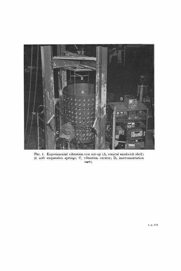
FIG. 1. Experimental vibration test set-up (A, conical sandwich shell; B. soft suspension springs; C, vibration exciter; D, instrumentation
cart).
f. p. 770

Vibrations of orthotropic sandwich conical shells with free edges 771
From these data, the modal strain distribution was determined. Once the data wereacquired, the shell nodal lines were investigated and checked approximately by feel andalso visually using the stroboscope.
The same procedure was repeated for each resonant frequency throughout the frequencyrange. Resonant frequencies were investigated from 5 to 400 cps. The lower limit was thelowest frequency of the exciter; the upper limit was reached when the strain signal-to.noise ratio was too low to obtain sufficiently reliable data.
5. ANALYSIS
Most of the analyses for sandwich-type shells have assumed simply supported edges,and a few assumed clamped edges. As stated in Section 1, this is probably due to theincreased mathematical complexity of the free-edge condition. In fact, only a very limitednumber of analyses of homogeneous, isotropic, conical shells with free edges have beencarried out, and these only quite recently.
After a careful review of previous analyses, it was decided to use the Rayleigh-Ritzmethod of analysis, but to include the inextensional modes only. This choice was moti·vated by these practical considerations: (1) the best agreement reported to date for theunsymmetric vibrations of free-free, homogeneous, isotropic shells was obtained by theinextensional analysis of Hu et al. ;9 (2) in a sandwich shell, the magnitude of the membranestrain energy relative to the bending strain energy is considerably smaller than that for ahomogeneous shell. (This is due to the difference in the ratio of membrane stiffness toflexural stiffness.) Thus, in a sandwich shell, the error introduced by neglecting membraneeffects is small except for the axisymmetric case (n = 0). This is clearly shown by anapproximate relation presented by PlatuslO for the natural frequencies, w, of a shell:
(1)
where We is the frequency calculated by considering only extensional effects and Wi is thefrequency calculated for the same n value but considering inextensional effects only. Inderiving equation (1), it is assumed that the modal functions associated with the twokinds of modes are geometrically similar, so that they affect the frequency only throughtheir effect on the stiffness. The hypothesis that the extensional effects are relatively smallfor a sandwich conical shell was verified, for the case of freely supported edges, by theanalysis of Bacon and Bert.n
The analysis presented in this section considers sandwich shells in the form of truncatedcones with orthotropic facings and a perfectly rigid core. All components of translationalinertia are included, but rotatory inertia is neglected.
Ref. 9 presented an inextensional analysis of a homogeneous, isotropic, conical shellwith free edges. Following Rayleigh's inextensional concept, the authors set the middlesurface strain components equal to zero and solved the resulting set of first-orderdifferential equations to obtain the following expressions for the inextensionaldisplacements:
u = A sin ex cos ex sin nO cos Wi t,
V = (A+B8/82)ncosexcosnOcoswit,
w = [A(n2-sin2ex) + Bn2 8/82] sin nO cos Wi t. J(2)
(3)
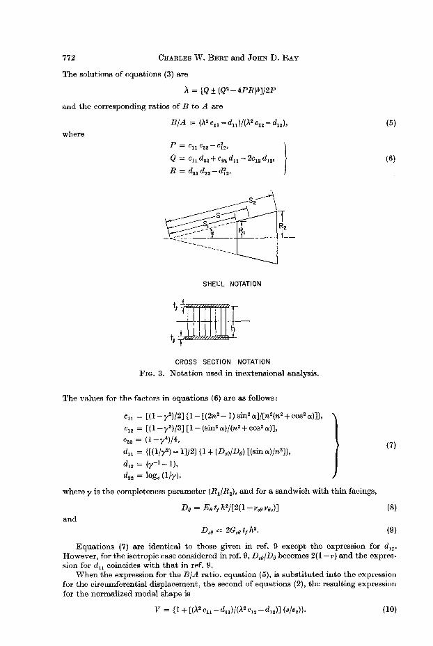
Here the same general approach as used in ref. 9 is employed, except that an orthotropicsandwich conical shell is considered (see Fig. 3).
The homogeneous, linear algebraic equations for the constants A and B appearing inequation (2) obtained from application of the Rayleigh-Ritz technique are as follows:
(,\2 Cll - dll ) A + (,\2 C12 - d12 ) B = 0,
(,\2 C12 - d12 ) A + (,\2 C12 - d22 ) B = O.
The eigenvalues, '\, for these equations are defined as follows:
(4)
772 CHARLES W. BERT and JOHN D. RAY
The solutions of equations (3) are
A = [Q ± (Q2 - 4PR)i]/2P
and the corresponding ratios of B to A are
(5)where
(6)
SHELL NOTATION
CROSS SECTION NOTATION
FIG. 3. Notation used in inextensional analysis.
The values for the factors in equations (6) are as follows:
Cu = [(I-y2)/2]{1-[(2n2-I)sin2();]/[n2(n2+cos2();)]),
C12 = [(I-y3)/3][1-(sin2 ();)/(n2 +cos2 ();)],
C22 = (l-y4)/4,
du = {[(I/y2) -1]/2} {I + (Dse/De) [(sin ();)/n2]},
d12 = (y-l_l),
d22 = log. (l/y),
where y is the completeness parameter (R1/R 2 ), and for a sandwich with thin facings,
and
(7)
(8)
(9)
Equations (7) are identical to those given in ref. 9 except the expression for du'However, for the isotropic case considered in ref. 9, Dae/Debecomes 2(I-v) and the expression for du coincides with that in ref. 9.
When the expression for the B/A ratio, equation (5), is substituted into the expressionfor the circumferential displacement, the second of equations (2), the resulting expressionfor the normalized modal shape is
(10)

Vibrations of orthotropic sandwich conical shells with free edges 773
Similarly, when equation (5) is substituted into the expression for normal displacement,the third of equations (2), the resulting expression for the normalized modal shape is
(11)
(12)
Since the middle surface extensional strains and the meridional bending strain are zero,the only strain existing is the circumferential bending strain, ebB' The circumferentialsurface bending strain is
where KB is the change in circumferential curvature.Thus, the meridional distribution of the dimensionless circumferential surface bending
strain is(13)
6. EXPERIMENTAL AND ANALYTICAL RESULTS
Resonant frequencies for various meridional modes are shown in Fig. 4 as a functionof circumferential mode number. On this figure, the two curves drawn through the pointscalculated by the inextensional analysis presented in Section 5 are shown along with theexperimental resonant-frequency data. Each resonant point was obtained from a modifiedKennedy-Pancu plot. A typical plot that was used to separate the resonant frequenciesis shown in Fig. 5. As can be seen from the figure, separation of the resonant frequencieswhich were very close together was accomplished quite adequately by the KennedyPancu technique. It can be seen in Fig. 4 that the experimentally measured resonantfrequency points associated with the two lowest unsymmetric modes agree quite closelywith the frequencies calculated by the inextensional analysis over the range of circumferential wave numbers.
The resonant-frequency curves for the higher modes indicate the same trend as thosefor the two lowest modes. In the region of low circumferential wave numbers, n, thehigher modes were difficult to detect experimentally because the resonant frequencycoincided with the resonant frequency of another mode. At these lower resonant frequencies, the response of the mode having a higher n would dominate that of the lower-n mode.This problem was one of the major difficulties encountered in applying the KennedyPancu technique in this investigation. It was beyond the scope of this investigationbecause of the limitation of equipment, but a solution to this problem would be to introduceadditional excitation systems. By placing the exciters near a point that is a node of thestrong mode, the system would exhibit a larger response in the weak mode.
4 80 r--,--,----,r-.,.--...,----,-,..-..,.-~-,-___,
10
PRESENTTHEORY
8642
INEXTENSIONALMODES
,GENERAL MODES IBIA
,Im;3 )/ 0
, , 0
/m=2~ / <>
, '/ /__ .__" / 0
/ <>0/ f. /
m=ly, /'
ff/0O'--'-----.L----..J_-'---'----'_L----L----'-_l.-...J
o
80
320
400
(f)
~ 240
>u~ 160::JollJcrlJ..
CIRCUMFERENTIAL WAVE NUMBER, n
FIG. 4. Experimental and analytical resonant frequency variations.

774 CHARLES W. BERT and JOHN D. RAY
At the lower circumferential wave numbers, it is believed that the higher modes willnot indicate as severe a hook in the resonant frequency vs. n plot as those reported inrefs. 2-4 for homogeneous-material conical shells. The reason for this was discussed inSection 5 in connexion with equation (1).
'PHASE ANGLE, '"
120°
0'4
60°
0·8
30°
1·2
RESPONSE FACTOR, Xo
FIG. 5. Kennedy-Pancu plot for 38·47 and 38·29 cps.
Shown as Figs. 6 and 7 are the plots of circumferential strain associated with the twolowest meridional modes. Also included in Figs. 6 and 7 are the analytical, circumferentialstrain distributions derived from the inextensional analysis presented in Section 5. Ingeneral, there is very good agreement between the analytical and experimental straindistributions for these modes. The effect of exciter mass and location is noticeable in themeridional modal shapes. However, this is to be expected since it was observed byMixson.5 The circumferential modal shapes are symmetric about the exciter location.
Fig. 8 shows a plot of the meridional strain distribution associated with the two lowestmeridional modes. The meridional strain distribution is identically zero in the inextensionalanalysis presented in Section 5. Although the curves indicate a meridional strain, thevalues are small and can be attributed to restraint of the shell from completely freemovement at the shaker-attachment location and at the suspension points.
n=3
n=2
IO~o 0
o 0
-1,0 EXPERIMENTAL DATA POINTS 0
o MODE A"'MODE B
1'0
°r~~~:-z~:==-1,0 PRESENT MODE A
THEORY' MODE B
oWN
::::i<[
::!;a:oz
>a:<[a:f-
aJa:<[
z<[a:frn
rnf-
Z:::J
n=5
I'OP~ '" 1",
OO~':'I0000=:= =a-",_-1'0 ! I I ! !! ~~
J IHGFEDC BASMALL LARGE
END ENDBODY STATIONS
FIG. 6. Normalized circumferential strain distribution along meridian,inextensional modes, n = 2-5.

Vibrations of orthotropic sandwich conical shells with free edges 775
1.0~n=6o '" '"o '-""==3::::~----'---"='P-..l...:o::!::-........L-
'" '"-1,0 0
~ EXPERIMENTAL DATA POINTSz MODE A::> MODE B
1·0>It:<:IIt:t-ID -1-0 PRESENT~ THEORY;
n=7
LARGEEND
I'D '" '" n=9
o 0 0 0 0
-1'0-+J-f-i---:H-;-;!G'--""'F;!-'-;kE-;!-6~c'-----!:B-A!-1 -
SMALLEND
Z<:IIt:t<f)
I': fS '" '" n=8
o 0 0 t::. t::. t::.
a -1-0 0
WN::::i<:I:0It:oZ
BODY STATIONS
Normalized circumferential strain distribution along meridian,inextensional modes, n = 6-9.
FIG. 7.
o n=2 D n=6<Do '" n=3 v n=8
x100I
t) MODE Az.....<f)w 50 vI Vt)
~ ~ ~ ~0 i l3. Az Ill. D ~V V
V
Z 0J H G F E D C B A
<:IIt: BODY STATIONSI-<f)
100u MODE B:::;;<:IZ
50>- v v0 v 0
~. * .8. f ~ ~ f 1 1!.DD 0 0
0 J H G F E 0 C B A
BODY STATIONS
FIG. 8. Meridional strain distribution along meridian, inextensionalmodes, n = 2, 3, 6, 8.
52
776 CHARLES W. BERT and JOHN D. RAY
Since the experimental data and the values derived by the inextensional analysis arein close agreement, it is assumed that the lowest experimental unsymmetrical modes arethe inextensional modes. The agreement is close for the resonant frequencies as a functionof circumferential wave number, for the circumferential strain as a function of meridionalposition and for the meridional strain as a function of meridional position.
Therefore, hereafter, these two lowest experimental modes will be referred to as theinextensional modes. The other modes which have higher resonant frequencies will bereferred to as general modes, since they exhibit both extensional and inextensionaldeformation as discussed in Section 5.
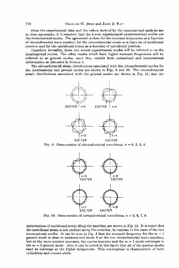
The circumferential strain distributions associated with the circumferential modes forthe inextensional and general modes are shown in Figs. 9 and 10. The circumferentialstrain distributions associated with the general modes are shown in Fig. 11, and the
EXCITER EXCITER
FIG. 9. Cross-section of circumferential waveforms, n = 0, 2, 3, 4.
FIG. 10. Cross-section of circumferential waveforms, n = 5, 6, 7, 8.
distributions of meridional strain along the meridian are shown in Fig. 12. It is noted thatthe meridional strain is not uniform along the meridian, in contrast to the cases of the twoinextensional modes. It can be seen in Fig. 4 that the resonant frequency for the m = 1general mode is close to inextensional mode B at the low circumferential wave numbers,but as the wave number increases, the curves separate and the m = 1 mode converges tothe m = 2 general mode. Also, it can be noted in this figure that all of the general modestend to converge at the higher frequencies. This convergence is characteristic of bothcylindrical and conical shells.
Vibrations of orthotropic sandwich conical shells with free edges 777
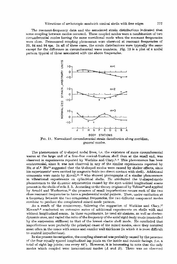
The resonant-frequency data and the associated strain distributions indicated thatsome coupling between modes occurred. These coupled modes were a combination of twocircumferential modes having the same meridional mode when the resonant frequencieswere close. Pronounced coupling phenomena were observed at resonant frequencies of33, 64 and 94 cps. In all of these cases, the strain distributions were typically the sameexcept for the difference in circumferential wave numbers. Fig. 13 is a plot of a nodalpattern typical of those associated with the above frequencies.
C/)
I-Z '0] m=1::::>
>- ~~a:<[ -I'~a:I- 0
CDa:<[-z '0] m=2<[
't>.e~, '~~a:I-C/) +~ 0
0
0WN...J<[
-::]m=3
~a:~~~~0
zo 0
! ! I ! I I 1 1
.J HGFEDCBA
BODY STATIONS
FIG. n. Normalized circumferential strain distribution along meridian,general modes.
The phenomenon of U-shaped nodal lines, i.e. the existence of more circumferentialwaves at the large end of a free-free conical-frustum shell than at the small end, wasobserved in experiments reported by Watkins and Clary.2,3 This phenomenon has beencontroversial, since it was not observed in any of the similar experiments reported byHu et al.' Hu12 suggested that the U-shaped modes were caused by shaker effects, sincehis experiments' were excited by magnetic fields (no direct contact with shell). Additionalcomments were made by Koval,13, 14 who showed photographs of a similar phenomenonin vibrational experiments on cylindrical shells. He attributed the U-shaped-modephenomenon to the dynamic asymmetries caused by the spot-welded longitudinal seamspresent in the shells of refs. 2, 3. According to the theory originated by Tobias15 and appliedby Arnold and Warburton,16 the presence of small imperfections causes each of the twoclose resonant frequencies to have a preferential nodal pattern. Then, under excitation ata frequency between the two component frequencies, the two different component modescombine to produce the complicated mixed-mode pattern.
As a result of the controversy, following the suggestion of Watkins and Clary,17Mixson5,6 conducted an extensive series of additional experiments on shells with andwithout longitudinal seams. In these experiments, he used air shakers, as well as electrodynamic ones, and varied the ratio ofthe frequency of the axial rigid-body mode (controlledby the suspension stiffness) to that of the lowest elastic shell mode. He concluded thatimperfections were probably the principal cause of the mixed modes, since they occurredmost often in the cones with seams and smaller wall thickness (in which it is more difficultto control imperfections).
In the present investigation, the coupling observed was probably caused by the presenceof the four equally spaced longitudinal lap joints on the inside and outside facings. (i.e. atotal of eight lap joints; one every 45°). However, it is interesting to note that the onlymodes which coupled were inextensional modes (A and B). There was no observed

778 CHARLES W. BERT and JOHN D. RAY
coupling of the general modes (m = 1,2, 3) with each other or with the inextensionalmodes. This may have been because, for the particular shell construction and geometry,the inextensional modes were the only ones sufficiently close together (in frequency as wellas in circumferential wave number) to couple.
m=1o n=3
I~:tl>n=4
l> l> on=5 l>l> 0
0 0.. 8 .s B ! 0~ ~ 30
x:I:C>Z.....
m=2 on=5en
I~:tl>n=6w
:I: • l> 4 &C> & A B b AZ
Z<la:I- o n=3en
I~;tm=3 l> n=6
C>
:::;; B. & B. .& & {l .& & .8.<lZ>-0
J I H G F E 0 C B A
BODY STATIONS
FIG. 12. Meridional strain distribution along meridian, general modes.
SHELL LAYOUT
FIG. 13. Nodal pattern for coupled mode at 94 cps.
At present, the authors know of no analytically based criterion for determining a prioriwhether or not two adjacent modes will couple to form a combined mode. Since theavailable experimental data are limited and expensive to obtain, an analytically basedcriterion, rather than an empirically based one, would be quite useful.
For calculating the frequencies of certain higher modes peculiar to sandwich structures,Yu's analysis18 was used. The calculated frequencies for all three of these modes (shearmodes in both the meridional and circumferential planes and the thickness-normal mode)were much higher than the highest frequencies attained in the experiments. Therefore, itis presumed that no modes of these types were excited in the experiments reported.
7. CONCLUSIONS
For free-free sandwich shells with orthotropic facings, an inextensionalanalysis predicts quite accurately the resonant frequencies associated with thefirst two unsymmetric modes. Under the conditions of the present experiments,extensional, core shear, and core normal effects can be neglected for thesetwo modes.
Vibrations of orthotropic sandwich conical shells with free edges 779
Combined modes with V-shaped nodal patterns, as reported in previousexperiments on free-free cones, were present. However, in all cases observedhere they represented coupling between inextensional modes only.
REFERENCES
1. N. L. ROUST, Vibration and Fatigue Sandwich Bibliography. Rexcel Corp., Dublin,Calif. (20 January, 1968).
2. J. D. WATKINS and R. R. CLARY, Vibrational Oharacteristics of Some Thin-walledOylindrical and Oonical Frustum Shells, NASA TN D·2729 (1965).
3. J. D. WATKINS and R. R. CLARY, Am. Inst. Aer. Astr. J. 2, 1815 (1964).4. W. C. L. Ru, J. F. GORMLEY and U. S. LINDHOLM, Flexural Vibrations of Oonical
Shells with Free Edges, NASA CR-384 (1966).5. J. S. MIXSON, J. Spacecraft and Rkts. 4, 414 (1967).6. J. S. MIXSON, Experimental Modes of Vibration of 14° Oonicaljrustum Shells, NASA
TN D-4428 (1968).7. C. W. BERT, W. C. CRISMAN and G. M. NORDBY, J. Aircraft 5, 27 (1968).8. J. D. RAY, C. W. BERT and D. M. EGLE, The Application of the Kennooy-Pancu
Method to Experimental Vibration Studies of Oomplex Shell Structures, presented at the39th Shock and Vibration Symposium, Monterey, Calif. (22-24 October, 1968).
9. W. C. L. Ru, J. F. GORMLEY and U. S. LINDHOLM, Int. J. mech. Sci. 9, 123 (1967).10. D. R. PLATUS, Oonical Shell Vibrations, NASA TN D·2767 (1965).n. M. D. BACON and C. W. BERT, Am. Inst. Aer. Astr. J. 5, 413 (1967).12. W. C. L. Ru, discussion of Ref. 3, Am. Inst. Aer. Astr. J. 3, 1213 (1965).13. L. R. KOVAL, J. acoust. Soc. Am. 35, 252 (1963).14. L. R. KOVAL, Am. Inst. Aer. Astr. J. 4, 571 (1966).15. S. A. TOBIAS, Engineering 172, 409 (1951).16. R. N. ARNOLD and G. B. WARBURTON, Proc. R. Soc. 197A, 238 (1949).17. J. D. WATKINS and R. R. CLARY, authors' reply to discussion of Ref. 3, Am. Inst. Aer.
Astr. J. 3, 1213 (1965).18. Y.-Y. Yu, J. appl. Mech. 27, 653 (1960).