shear moment - university of...
TRANSCRIPT

500N
VP
Mbx+dx
500N
VP
Max
SHEAR AND MOMENT DIAGRAMS 1Problem: Find transverse shear force (V) and bending moment (M) in frame member at a given cross-section locationSolution: P, V, M free body diagram and statics
Problem: Find worst case cross-section (transverse shear force (V) and bending moment (M) ) in frame memberSolution: Shear and Moment Diagram
Statics Sign Conventions P, V, M positive sign convention
1 Draw free-body diagram for section A-a and find V and M as ƒ(V)
2 Draw free-body diagram for section A-b and find V and M as ƒ(V)
3 Write general equationdM = Mb - Ma as ƒ(V, x, dx)
Positive Forces1st Quadrant
Positive MomentCounterclockwise
∑ F y=0=500N−VV=500N
∑M A=0=−(V )(x )+M a
M a=(V )( x)
∑ F y=0=500 N−VV=500N
∑M A=0=−(V )(x+dx )+M b
M b=(V ) ( x )+(V )(dx )
M b−M a=[ (V ) ( x )+(V )(dx)]− (V )(x)dM=V dx
V does not change with x
M changes with x
4 Slope/Area method” (cook-book method) to Plot Shear and Moment Diagrams
Start M plot with boundary condition (M at x=0)
Slope of M plot is value of V Change in M value is area of V vs x plot
V plot exactly follows loads.
V=dMdx
∫ dM=∫V dx
MA
AA B
SHEAR AND MOMENT DIAGRAMS 2
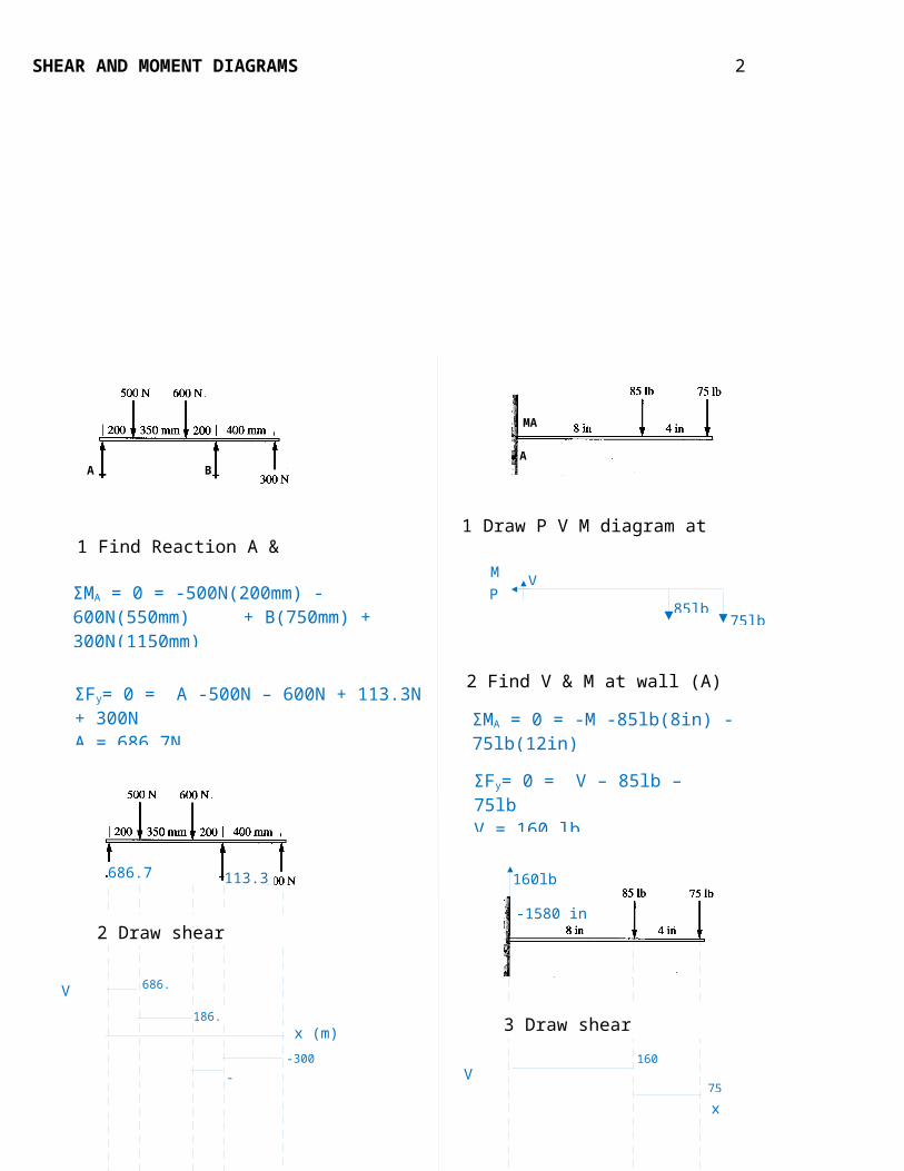
1 Find Reaction A & B1 Draw P V M diagram at wall, A
2 Find V & M at wall (A) using statics
HW#17
ΣMA = 0 = -500N(200mm) -600N(550mm) + B(750mm) + 300N(1150mm)B = 113.3N
ΣFy= 0 = A -500N – 600N + 113.3N + 300N A = 686.7N
686.7N 113.3N
V (N)
x (m)
M (Nm)
x (m)
686.7
186.7
-413.8-300
0.2m 0.35m 0.2m 0.4m
137.3202.7
120
75lb
VPM
85lb
ΣMA = 0 = -M -85lb(8in) -75lb(12in) M = -1580 in lb
ΣFy= 0 = V – 85lb – 75lb V = 160 lb
160lb
-1580 in lb
V (lb)
M (in lb)
160
75x (in)
x (in)
-1580
-300
8 in 4 in
-1580+(160)(8)=-300
2 Draw shear diagram
3 Draw moment diagram
3 Draw shear diagram
4 Draw moment diagram
FE
24kN
39kN-15kN
24kN
400mm 250mm
V (kN)
-15
24kN
M(kNmm)
400mm
250mm
-6000
SHEAR AND MOMENT DIAGRAMS 3
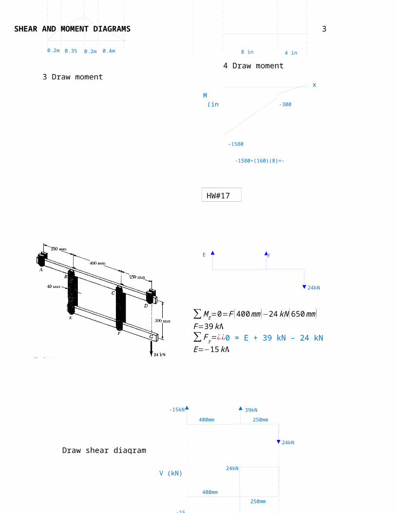
∑M E=0=F ( 400mm )−24 kN (650mm )F=39 kN∑ F y=¿¿0 = E + 39 kN – 24 kNE=−15kN
Draw shear diagram
Draw moment diagram