shasta county local agency management program …
TRANSCRIPT

SHASTA COUNTY LOCAL AGENCY MANAGEMENT PROGRAM (LAMP) FOR ONSITE WASTEWATER TREATMENT SYSTEMS (OWTS)
1 REQUIRED POLICY ELEMENTS A. BACKGROUND……………………………………………………………… Page 1 B. POLICY TIERS………………………………………………………………. Page 1 C. INTENT……………………………………………………………………….. Page 2 D. DEFINITIONS………………………………………………………………… Page 3 E. PROHIBITIONS/EXCEPTIONS……………………………………………… Page 11 F. EXISTING PARCELS………………………………………………………… Page 13 G. SEPTAGE CAPACITY AND SEPTIC PUMPER TRUCK APPLICATIONS AND
REGISTRATIONS……………………………………………………….. Page 13 H. DATA COLLECTION/REPORTING/NOTIFICATION/RESPONSIBILITIES Page 14 I. OWTS NEAR IMPAIRED WATER BODIES/ONSITE MAINTENANCE
DISTRICTS/REGIONAL SALT AND NUTRIENT MANAGEMENT PLANS/WATERSHED MANAGEMENT……………………………………..……. Page 19
J. PARCEL/LOT SIZE REQUIREMENTS…………………………………… Page 20 K. HIGH DOMESTIC WELL USAGE AREAS……………………………….. Page 20 L. CESSPOOLS……………………………………………………………… Page 20 M. RV HOLDING TANK WASTE………………………………………………… Page 21
2 OWTS PERMITTING PROCESS….………………………………………….. Page 21 A. STATE, COUNTY AND CITY ROLES…………………………………….. Page 21 B. SYSTEM DESIGN CONSIDERATIONS…………………………………….. Page 21 C. PERMITS ISSUED……………………………………………………………... Page 23 D. PERMIT APPLICATION PROCESS……………………………………………. Page 24 E. PERMIT APPLICATION REVIEW AND PERMIT ISSUANCE……………. Page 25 F. FINAL INSPECTION…………………………………………………………... Page 26 G. PRIMARY AND REPLACEMENT/RESERVE AREA REQUIREMENTS…… Page 26 H. SEPTIC TANKS…………………………………………………………………. Page 27 I. ALTERNATIVE OWTS TREATMENT SYSTEMS…………………………... Page 27 J. OWTS LEACHLINE DISPERSAL SYSTEMS………………………………… Page 27 K. SETBACKS/VARIANCES…………………………………………………….. Page 27 L. PROXIMITY TO PUBLIC SEWERS…………………………………………... Page 27
3 FAILING OWTS AND CORRECTIVE ACTION……………………………. Page 29 A. FAILURE OF A LEACHFIELD……………………………………………… Page 29 B. CORRECTIVE ACTION REQUIREMENTS…………………………………. Page 30 C. SUBSTANDARD SYSTEMS………………………………………………….. Page 32

APPENDICES
TECHNICAL STANDARDS MANUAL INTRODUCTION…………………………………………………...…………... Page 33 A. GROUNDWATER SEPARATION REQUIREMENTS FOR OWTS AND OVERALL SOIL DEPTH DETERMINATIONS……………………………. Page 34 B. SOIL PROFILE PITS AND GROUNDWATER MONITORING…………….. Page 36 C. PERCOLATION TEST PROCEDURE………………………………………... Page 41 D. SEPTIC TANKS, SUMPS, AND PUMPS……………………………………… Page 46 E. LEACH LINE DISPERSAL SYSTEMS…………………………………………. Page 50 F. SUPPLEMENTAL TREATMENT SYSTEMS………….……………………… Page 56 G. ALTERNATE DISPERSAL SYSTEMS………………………………………… Page 67
STANDARDS FOR SHALLOW PRESSURE DISTRIBUTION SYSTEM…… Page 70 STANDARDS FOR MOUND SYSTEM………………………………………… Page 74 STANDARDS FOR AT GRADE SYSTEM…………………………………… Page 81 STANDARDS FOR PRESSURE DOSE SAND LINED TRENCH SYSTEM… Page 87 STANDARDS FOR DRIP DISPERSAL SYSTEM……………………………… Page 92 STANDARDS FOR CURTAIN DRAINS………………………………………… Page 97
H. SAMPLE SYSTEM SIZING CALCULATIONS…………………………………. Page 101 I. INSPECTION FREQUENCY AND SYSTEM MAINTENANCE……………….. Page 107
TABLES 1. RESIDENTIAL DISPERSAL SYSTEM SIZING…………………………….. Page 110 2. SOIL APPLICATION RATES FOR SYSTEM SIZING…………………......... Page 113 3. HORIZONTAL SETBACKS…………………………………………………... Page 114

1
SHASTA COUNTY LOCAL AGENCY MANAGEMENT PROGRAM FOR ONSITE WASTEWATER TREATMENT SYSTEMS
LAMP SECTION 1 REQUIRED POLICY ELEMENTS
1. A. BACKGROUNDThe California Water Code authorizes the State Water Resources Control Board (SWRCB) to regulate alldischarges, including those from Onsite Wastewater Treatment Systems, which could adversely impact waterquality. The policies of the SWRCB are implemented locally through nine Regional Water Quality ControlBoards. Historically, each regional board developed basin plans that outlined water quality objectives in theirrespective jurisdictions as well as policies and programs to achieve those objectives.
Discharges are regulated through the use of Waste Discharge Requirements (WDRs). Shasta County is in Region Five which is the Central Valley Regional Water Quality Control Board (CVRWQCB). The SWRCB regulatory authority extends to individual Onsite Wastewater Treatment Systems (OWTS). General guidelines for the Siting, Design, and Construction of OWTS were part of each regional board’s basin plans. The SWRCB and the regional boards recognize the advantages and efficiencies of OWTS regulation by local agencies. Consequently, while the regional boards retained primacy over large and specialized systems, direct regulatory authority for individual OWTS has been delegated to individual counties that implement the regulations through a Local Agency Management Program (LAMP).
The State OWTS Policy and LAMP are the culmination of the actions required by Assembly Bill 885 (AB 885). AB 885 as introduced to the California State assembly on February 25, 1999, would have impacted only coastal counties. However, the final version approved on September 27, 2000, was more inclusive, affecting all California counties. This legislation directed the SWRCB to develop regulations or standards for OWTS to be implemented statewide by qualified local agencies that issue sewage disposal system permits, which in Shasta County is the Environmental Health Division of the Department of Resource Management (SCEHD).
The SWRCB adopted the Water Quality Control Policy (State OWTS Policy) for Siting, Design, Operation, and Maintenance of Onsite Wastewater Treatment Systems on June 19, 2012. The Policy was subsequently approved by the Office of Administrative Law on November, 13, 2012, and became effective on May 13, 2013. The OWTS Policy allows local agencies to approve OWTS, based on a local ordinance, and LAMP after approval by the applicable regional board.
Without an approved LAMP the County could only issue septic system permits for those few sites meeting the restrictive soil requirements of State OWTS Policy Tier 1. All other sites would potentially be subject to the WDR process. However, under an approved LAMP, the requirement to obtain WDRs is conditionally waived for OWTS that are in conformance with the LAMP.
1. B. POLICY TIERSThe State OWTS Policy places OWTS in California into one of the following Tiers:

2
TIER 0 – Existing OWTS. These are defined as existing OWTS that are properly functioning, and do not meet the conditions of failing. These do not require corrective action as specifically described in Tier 4, and are not contributing to an impairment of surface water as specifically described in Tier 3. TIER 1 - Low-risk new or replacement OWTS. These are new or replacement OWTS that meet low risk siting and design requirements as specified in Tier 1. Minimum soil depths to groundwater and minimum soil depth from the bottom of a dispersal system range from 5 to 20 feet, based on soil percolation rates. TIER 2 - Local Agency Management Program for new and replacement OWTS. California is known for its extreme range of geological and climatic conditions. As such, the establishment of a single set of criteria for OWTS would either be too restrictive so as to protect the most sensitive case, or would have broad allowances that would not be protective enough under some circumstances. To accommodate this extreme variance, local agencies may submit management programs known as Local Agency Management Programs (LAMP) for approval by the Regional Water Quality Control Board, then upon approval, manage the installation of new and replacement OWTS under that Program. An approved LAMP allows local agencies to develop customized management programs that address the soil conditions and groundwater depths specific to that jurisdiction. Under an approved LAMP, separation of the bottom of a dispersal system to groundwater of as little as two feet may be allowed with an approved OWTS utilizing supplemental treatment and/or an alternate dispersal system. Once approved, the standards contained in an approved LAMP supersede the Tier 1 standards. However, standard systems meeting Tier 1 soil and siting criteria could still be constructed. TIER 3 - Impaired Areas. Systems that are within 600 feet of impaired water bodies. There are no such water bodies identified within Shasta County. TIER 4 - OWTS Requiring Corrective Action. OWTS that require corrective action or fail at any time while the State OWTS Policy is in effect are automatically in Tier 4 and must follow Tier 2 requirements pending completion of corrective action. 1. C. INTENT The Shasta County Environmental Health Division (SCEHD) is committed to protecting public health and water quality while allowing continued development in Shasta County. In conformance with the State OWTS Policy, Shasta County intends to regulate wastewater flows of normal domestic strength up to 10,000 gallons per day for dispersal underground only. Regulation of projects that may have waste strength greater than normally found in domestic flows usually evaluated by SCEHD staff and any project with a projected flow nearing or exceeding 10,000 gallons per day will be coordinated with the CVRWQCB staff. (OWTS Policy 9.2) (OWTS Policy 9.4.2) (OWTS Policy 9.4.3) This LAMP includes a number of different system design options, including a variety of supplemental treatment systems and alternate dispersal systems, which are described in the Technical Standards Manual, to allow for the construction of the least complicated and least costly system that meets the intent of the State OWTS Policy.

3
1. D. DEFINITIONS “303 (d) List” means the same as Impaired Water Bodies. “State OWTS Policy” or Policy means the OWTS Policy adopted by the State Water Resources Control Board requiring the preparation of a Local Agency Management Program (LAMP). “Alternative treatment systems” include intermittent and recirculating sand filters, proprietary treatment units, and other alternative treatment systems approved by the Director. Generally referred to as “supplemental” treatment systems in this LAMP. “Alternate dispersal systems” include shallow trench pressure distribution, mound, At-grade, drip dispersal, and other alternative dispersal systems approved by the Director. Some alternate dispersal systems can be used without the need for a supplemental treatment system. “At-grade system” means an OWTS dispersal system with a discharge point located at the preconstruction grade (ground surface elevation) with qualifying fill material used to cover the dispersal system. The discharge point of an At-grade system is, therefore, always subsurface. “Average” means the number calculated by dividing the sum of the values in the set by their number. “Average annual rainfall” Means the average annual amount of precipitation for a location over a year as measured by the nearest National Weather Service station for the preceding three decades. For example, the data set used to make a determination in 2015 would use the data from 1984 to 2013. “Bedrock” means the rock, usually solid, that underlies soil or other unconsolidated, surficial material. “Biomat” is a bacterial slime layer which forms in soil at the bottom of leach lines and other dispersal systems. It is responsible for much of the treatment and reduction of biological solids and bacteria present in onsite wastewater treatment system effluent (from either a septic tank or supplemental treatment system) discharged to the soil. “Building Sewer” means that part of the horizontal piping of a drainage system that extends from the end of the building drain and that receives the sewage discharge of the building drain and conveys it to the OWTS. “CEDEN” means California Environmental Data Exchange Network and information about it is available at the State Water Board or its website or at the CEDEN website which is located at http://www.ceden.org/index.shtml at the time of adoption of this LAMP. “Cesspool” means an excavation in the ground receiving domestic wastewater, designed to retain the organic matter and solids, while allowing the liquids to seep into the soil. Cesspools have not been approved for use in Shasta County. Cesspools do not have septic tanks and are not authorized under this Policy. Any cesspool found in use will be required to be destroyed and replaced by a properly designed and constructed OWTS.

4
“Chroma” is a measure of color purity in the Munsell color system. “Clay” means a fine-grained natural rock or soil particle that combines one or more clay minerals with traces of metal oxides and organic matter. This term also refers to a soil texture. Particle size would not exceed 0.002 nm. “Cobbles” means rock fragments 76 mm or larger using the USDA soil classification system. “Community disposal fields” are fields that serve more than two (2) dwelling units. “Conventional onsite water treatment system” means an OWTS constructed in soil meeting Tier 1 specifications. A conventional OWTS consists of a septic tank and a series of subsurface dispersal trenches for subsurface dispersal of effluent into the soil. A conventional OWTS may utilize gravity flow or a pump system to convey effluent from the septic tank to the drain field. “Curtain drain or French drain” is a gravel trench that is excavated down to a relatively impermeable soil layer and installed to intercept, collect, and remove shallow subsurface groundwater as it flows above the impermeable layer. “Cut or embankment” means any altered area of land surface having a distinctly greater slope than the adjacent ground surface, over 24 inches in vertical height or the OWTS dispersal system backfill cover depth, whichever is greater, and any part of which is lower in elevation than the ground surface at the nearest point of the OWTS. Cuts supported by retaining walls or other similar structures shall be included in this definition, as shall be steep natural ground surfaces where a sharp break in the ground slope is discernable. “Director” means the Director of Environmental Health or his/her designee in the Shasta County Environmental Health Division of the Department of Resource Management. “Dispersal system” means a series of trenches, beds, subsurface drip lines, or other approved method for subsurface infiltration and absorption of wastewater effluent, including all component parts such as piping, valves, filter material, chambers, dosing pumps, siphons, and other appurtenances. “Domestic wastewater” means wastewater with a measured strength less than high-strength wastewater and is the type of wastewater normally discharged from, or similar to, that discharged from plumbing fixtures, appliances, and other household devices including, but not limited to toilets, bathtubs, showers, laundry facilities, dishwashing facilities, and garbage disposals. Domestic wastewater may include wastewater from commercial buildings, such as office buildings, retail stores, and some restaurants, or from industrial facilities where the domestic wastewater is segregated from the industrial wastewater. Domestic wastewater does not include industrial wastewater or wastewater consisting of a significant portion of RV holding tank wastewater such as at RV dump stations. “Domestic well” means a groundwater well that provides water for human consumption and is not regulated by the California Department of Public Health.

5
“Drainage way” for purposes of this Policy means an intermittent, seasonal, or perennial waterway which continues to flow at least five (5) days after a storm and as measured from the top of the bank or other physically evident high water line. “Drain field” means a system of rock-filled trenches or beds that distribute treated effluent for subsurface dispersal into the soil. A drain field is also known as a “leach field” or “soil absorption or dispersal system”. “Dredger tailings” for purposes of this Policy means the accumulated gravels and sands separated from soil primarily in gold dredging operations. “Dump Station” means a facility intended to receive the discharge of wastewater from a holding tank installed on a recreational vehicle. A dump station does not include a full hook-up sewer connection similar to those used at a recreational vehicle park. “Earthen material” means a substance composed of the earth’s crust (i.e., soil and rock). “EDF” or Electronic Deliverable Format means the data standard adopted by the State Water Board for submittal of groundwater quality monitoring data to the State Water Board’s internet-accessible database system GEOTRACKER (located at http://geotracker.waterboards.ca.gov as of the time of adoption of this LAMP). “Effluent” means sewage, water, or other liquid, partially or completely treated or in its natural state, flowing out of a septic tank, aerobic treatment unit, dispersal system, or other OWTS component. “Engineered fill” means a designed placement of specified imported soil over existing native soils on an existing parcel with inadequate soil depth to meet the minimum two (2) to three (3) feet of soil depth required beneath a dispersal system, and a minimum of two (2) to three (3) feet of separation between the bottom of a dispersal system and a water table. “Ephemeral drainage” for purposes of this LAMP, means a stream, or other drainage such as a roadside ditch, that flows for less than five days after the passage of a storm. An ephemeral stream only carries water in direct response to a precipitation event and it contains no water from a spring, snow, or other long-continuing surface source. Setback measurements are made from the edge of the channel. “Existing OWTS” means an OWTS in which a valid construction permit has been issued or that was constructed and operated prior to the adoption of standards developed in response to the State OWTS Policy. “Existing Parcel” means any legally established vacant or developed parcel that was in existence prior to the adoption of standards developed in response to the State OWTS Policy. “Failure” means the ineffective dispersal of waste resulting in the surfacing of sewage or inadequately treated sewage effluent and/or the degradation of surface or groundwater quality. “GeoTracker” is the SWRCB data management system for managing sites that impact groundwater, especially those that require groundwater cleanup.

6
“Gleying” is the process of waterlogging and reduction in soils. Gleyed soils are soils developed under conditions of poor drainage and can generally be found as surface water and ground water gleys. “Groundwater” means water that is below the land surface that is at or above atmospheric pressure. “High-strength wastewater” means wastewater having a 30-day average concentration of biochemical oxygen demand (BOD) greater than 300 milligrams-per-liter (mg/l) or of a total suspended solids (TSS) greater than 330 mg/l or a fats, oil, and grease (FOG) greater than 100 mg/l prior to the septic tank or other OWTS treatment component. “IAPMO” means the International Association of Plumbing and Mechanical Officials. “Impaired water bodies” means those surface water bodies or segments thereof that are identified on a list approved first by the State Water Board and then approved by the US EPA pursuant to Section 303(d) of the federal Clean Water Act. “Intermittent sand filter” means a packed-bed filter of medium-grained sand used to treat septic tank effluent to an advanced level. Wastewater is dosed to the surface of the sand through a pressure-distribution network and allowed to percolate through the sand where BOD is reduced and suspended solids are removed; treatment is accomplished by physical filtration as well as microbial growth on the surface of the sand grains. After a single pass, the effluent is collected in an underdrain system for further processing or dispersal. “Intermittent Stream” is a stream or other drainage that flows for more than 5 days per year but does not continue to flow the entire year. “Irrigation ditch or canal” means a man-made lined or unlined ditch intended to supply dry land with water and must meet the setbacks specified for ephemeral, intermittent, or seasonal drainage ways except as allowed otherwise. “Linear Loading Rate” is defined as the amount of effluent, in gallons, applied per day, per lineal foot of the dispersal system. The “amount” is the total of all parallel dispersal systems along a contour. The design linear loading rate is a function of effluent movement rate away from the dispersal system and the direction of flow away from the dispersal system. “Local agency” for purposes of this Policy means the Environmental Health Division of the Shasta County Department of Resource Management. “Local Agency Management Program (LAMP) means this document to be used for siting, evaluation, design, operation, and management of onsite wastewater systems within Shasta County. “Major repair” means either (1) for a dispersal system, repairs required for an OWTS dispersal system due to surfacing wastewater effluent from the dispersal field and/or wastewater backed up into plumbing fixtures because the dispersal system is not able to percolate the design flow of wastewater associated with the structure served, or (2) for a septic tank, repairs required to the tank for a compartment baffle failure or tank structural integrity failure such that either wastewater is leaking out of or groundwater is infiltrating. A permit to repair a major

7
failure is required from SCEHD and all systems, after repair, must be in compliance with their respective sections of this LAMP. “Minor repair” means a failure of a component other than a septic tank, treatment system, or dispersal system such as a distribution box or broken piping connection. A permit to repair this failure is required from SCEHD. “Mottling” means a soil condition that results from oxidizing or reducing minerals due to soil moisture changes from saturated to unsaturated over time. Mottling is characterized by spots or blotches of different colors or shades of color (grays and reds) interspersed within the dominant color as described by the USDA soil classification system. The soil condition can be indicative of historic seasonal high groundwater level, but the lack of this condition may not demonstrate the absence of groundwater. “Mound system” means a dispersal system (covered sand bed with effluent leach field elevated above original ground surface inside the mound) used to enhance soil treatment, dispersal, and absorption of effluent from an OWTS treatment unit such as a septic tank. Mound systems are considered subsurface discharge. “New OWTS” means an OWTS permitted after the approval date of this LAMP. “Non-conventional OWTS” means a system that is not a conventional septic tank/leach field system, and uses an alternative treatment and/or dispersal system to mitigate shallow soil depth and/or depth to groundwater. “NSF” means NSF International (a. k. a. National Sanitation Foundation), a not for profit, non-governmental organization that develops health and safety standards and performance product certification. “Onsite wastewater treatment system(s) (OWTS)” means individual treatment and dispersal systems, community treatment and dispersal systems, and alternative treatment and dispersal systems that collect and treat wastewater for subsurface dispersal. The short form of the term may be singular or plural. OWTS do not include “gray water” systems pursuant to Health and Safety Code section 17922.12. “Ped” means an individual natural soil aggregate. “Perennial Waterway” is a stream or other drainage which has continuous flow in all or parts of its stream bed all year during normal rainfall years but may flow only intermittently in drought years. “Percolation test” means a method of testing the water absorption ability of the soil. The test is conducted with clean water and test results are used to establish a percolation rate and facilitate the dispersal system sizing and design. “Permeable soil” means soil that has a percolation rate of 120 minutes per inch or faster or having a clay content of less than 60 percent, and shall not contain solid rock formations or those that contain continuous channels, cracks, or fractures. “Permit” means a document issued by SCEHD that allows the installation and use of an OWTS.

8
“Permitting authority” for purposes of this Policy means the Environmental Health Division of the Shasta County Department of Resource Management. “Person” means any individual, firm, association, organization, partnership, business trust, corporation, company, State agency or Department, or unit of local government who is, or that is subject to this Policy. “Pit-privy” (a. k. a. outhouse or pit-toilet) means self-contained waterless toilet used for disposal of non-water carried human waste; consists of a shelter built above a pit in the ground into which human waste falls. Unlined pits are not allowed by this LAMP. “Policy or State OWTS Policy” means the Water Quality Control Policy adopted by the State Water Resources Control for Siting, Design, Operation, and Maintenance of Onsite Wastewater Treatment Systems on June 19, 2012, requiring the preparation of a Local Agency Management Program (LAMP). “Pollutant” means any substance that alters the waters of the State to a degree that it may potentially affect the beneficial uses of water, as listed in a Basin Plan. “Precipitation” means measureable amounts of rain, snow, hail, and other similar natural phenomenon. “Projected flows” means wastewater flows into the OWTS determined in accordance with any applicable methods for determining average daily flow as approved by the Director, in accordance with this LAMP. “Public water system” is a water system regulated by the California Department of Public Health or a local Primacy agency pursuant to Chapter 12, Part 4, California Safe Drinking Water Act, Section 116275(h) of the California Health and Safety Code. “Public water well” is a ground water well serving a public water system. A spring which is not subject to the California Surface Water Treatment Rule (SWTR), Title 22 of the California Code of Regulations, Sections 64650 through 64666, is considered a public well. “Qualified Professional” means an individual licensed or certified by a State of California agency to design OWTS and practice as professionals for other associated reports, as allowed under their license or registration. Depending on the work to be performed and various licensing and registration requirements, this may include an individual who possesses a registered environmental health specialist certificate or is currently licensed as a professional engineer. For the purposes of performing site evaluations, Soil Scientists certified by the Soil Science Society of America are considered qualified professionals. Qualified professionals would be expected to conduct onsite surveys for OWTS suitability, evaluate potential pathways of wastewater-sourced phosphate and other nutrients toward potentially threatened nearby wells or surface bodies of water, consider hydraulic mounding and linear loading at the site, complete all necessary soils tests, prepare system designs and drawings, meet with owners and installers, and conduct necessary inspections. No other person, license, or registration/certification will be approved as a Qualified Professional. (OWTS Policy 9.1.7) “Regional Water Quality Control Board (RWQCB)” for purposes of this Policy, means the Region 5 board. Any reference to the RWQCB in this document also refers to an action of its Executive Officer.

9
“Replacement OWTS” means an OWTS that has its treatment capacity expanded, or its dispersal system replaced or otherwise added onto, after the effective date of this Policy. An OWTS may be replaced for a variety of reasons including failure, home additions increasing the number of occupants/water use, relocation to accommodate home additions, home sales, and other reasons. “Sand” means a soil particle; this term also refers to a soil texture. As a soil particle, sand consists of individual rock or mineral particles in soil having diameters ranging from 0.05 to 2.0 millimeters. “Saprolite” means soft, thoroughly decomposed and porous rock, often rich in clay, formed by the in-place chemical weathering of igneous, metamorphic, or sedimentary rocks. “SCEHD” means the Environmental Health Division of the Shasta County Department of Resource Management. “Seepage pits” means a vertical excavation constructed to receive effluent from a septic tank. As the State OWTS Policy requires a minimum of ten (10) feet of adequate soil and separation between the bottom of the pit and highest anticipated groundwater level and increased horizontal separation distances, it is not anticipated that permits will be issued for their construction and use in Shasta County. “Septage” is the term used for the partially treated and settled solid and liquid material removed from the septic tank (and some treatment systems) by septic tank pumper trucks. Septage includes settled solids, fats oils grease and other floating materials, and liquid. “Septic tank” means a water tight, covered receptacle designed for primary treatment of wastewater and constructed to:
1. Receive wastewater discharged from a building or other use; 2. Separate settleable and floating solids from the liquid; 3. Digest organic matter by anaerobic bacterial action; 4. Store undigested solids; and 5. Clarify wastewater for further treatment/subsurface discharge.
“Service provider” means a person capable of operating, monitoring, and maintaining an OWTS in accordance with this Policy. “Silt” means a soil particle; this term also refers to a soil texture. As a soil particle, silt consists of individual rock particles in soil having diameters ranging between 0.05 and 0.002 mm. “Site” means the location of the OWTS and, where applicable, a reserve dispersal area capable of disposing of 100 percent of the design flow from all sources the OWTS is intended to serve. “Site plan” means a site plot plan showing, at a minimum, all existing topographic features, the locations of all required soil tests, and all proposed site grading, structures and other existing/planned improvements.

10
“Site evaluation” means an assessment of the characteristics of the site and onsite soils sufficient to determine suitability for an OWTS to meet the requirements of this Policy. “Slope” means the rise or fall of vertical elevation in feet, per one hundred (100) feet of horizontal distance. Slope is expressed as a percent of grade. For example a rise of 30 feet in a 100 foot run is a 30 percent slope. A rise of 40 feet in a 100 foot run is a slope of 40 percent. “Soil” means the naturally occurring body of porous mineral and organic materials on and at the land surface, which is composed of unconsolidated materials, including sand-sized, silt-sized, and clay-sized particles mixed with varying amounts of larger fragments and organic material. The various combinations of particles differentiate specific soil textures identified in the soil textural triangle developed by the United States Department of Agriculture (USDA) as found in Soil Survey Staff, USDA; Soil Survey Manual, Handbook 18, U. S. Government Printing Office, Washington, DC, 1993, p. 138. For purposes of this Policy, soil shall contain earthen material of particles smaller than 0.08 inches (2mm) in size. For the purposes of this LAMP, soil is the ultimate receiver of wastewater and the most important part of an OWTS. Therefore, in addition to the depth to groundwater, the proper evaluation of soil structure, permeability, and overall useable soil depth is critical in the proper choice and design of an OWTS for any particular site. “Soil profile” is a natural sequence of layers, or horizons, in the soil as described in a suitable manner acceptable to SCEHD. “Soil structure” means the arrangement of primary soil particles into compound particles, peds, or clusters that are separated by natural planes of weakness from adjoining aggregates. “Soil texture” means the soil class that describes the relative amount of sand, silt, and clay and combinations thereof as defined by the classes of the soil textural triangle developed by the USDA. “State Water Board” means the State Water Resources Control Board. “Storm” for purposes of this policy means the receipt of measureable precipitation at the nearest measuring/reporting station. “Substandard system” means any existing OWTS that does not conform to the system sizing, setbacks, soil depth, or groundwater separation requirements of this Policy. “Supplemental Treatment” means any OWTS or component of an OWTS, except for a septic tank or dosing tank, that performs additional wastewater treatment so that the effluent meets a predetermined performance requirement prior to discharge of the effluent into the dispersal field. Also known as an alternative OWTS. Some supplemental treatment units are passive and can be placed directly onto a leach bed for direct dispersal into the soil. “SWAMP” means Surface Water Ambient Monitoring Program and more information is available at State Water Resources Board’s web site which is located at http://www.waterboards.ca.gov/water_issues/programs/swamp/ as of the time of adoption of this LAMP.
11
“TMDL” is the acronym for “total maximum daily load”. Section 303(d)(1) of the Clean Water Act requires each state to establish a TMDL for each impaired water body to address the pollutant(s) causing the impairment. In California, TMDL’s are usually adopted as Basin Plan amendments and contain implementation plans detailing how water quality standards will be attained. “USDA” means the U.S. Department of Agriculture. “Usable leaching material” for land division purposes has the following characteristics:
• Percolation rates greater than one (1) and less than one hundred twenty (120) minutes per inch when tests are conducted by the method specified in the Manual of Septic Tank Practice, U.S. Department of Health and Human Services or other similar method specified in this LAMP;
• Depth to a seasonal water table, as determined by the procedures specified in this LAMP, shall be at least four (4) feet for lots of one (1) or more acres and at least eight (8) feet for lots less than one (1) acre; and,
• The area with these soils must meet all applicable treatment and/or dispersal system setbacks including setbacks from property lines.
“Vulnerable surface water” means surface water vulnerable to biological and chemical contamination from an OWTS. “Waste Discharge Permit” or “WDR” means an operation and discharge permit issued for the discharge of waste (including septic system effluent) pursuant to Section 13260 of the California Water Code. 1. E. PROHIBITIONS (OWTS Policy 9.4) a. Pursuant to the State OWTS Policy, the following will not be authorized in this LAMP:
• Cesspools of any kind or size. (OWTS Policy 9.4.1)
• OWTS receiving a projected flow over 10,000 gallons per day. (OWTS Policy 9.4.2)
• OWTS that utilize any form of effluent dispersal that discharges on or above the post installation ground surface such as sprinklers, exposed drip lines, free-surface wetlands, a pond, or any other similar surface discharge. (OWTS Policy 9.4.3)
• Slopes greater than 30 percent without a slope stability report approved by a registered professional.
(OWTS Policy 9.4.4)
• Decreased leaching area for IAPMO certified dispersal systems using a multiplier less than 0.70. (OWTS Policy 9.4.5)
• OWTS utilizing supplemental treatment without requirements for periodic monitoring or inspections.
(OWTS Policy 9.4.6.)
• OWTS dedicated to receiving significant amounts of wastes dumped from RV holding tanks. (OWTS Policy 9.4.7)

12
• Separation of the bottom of dispersal system to groundwater less than two feet. (see Technical Standards
Manual) (OWTS Policy 9.4.8)
• Installation of new or replacement OWTS where public sewer is available. The public sewer may be considered unavailable when such public sewer or any building or exterior drainage facility connected thereto is located more than 200 feet from any proposed building or exterior drainage facility on any lot or premises that abuts and is served by such public sewer. We recognize that some local agencies have a policy requiring connection within 200 feet of property lines rather than the 200 feet from proposed buildings or exterior drainage facility and will use this standard where a conflict exists. This requirement to connect provision does not apply to replacement OWTS where the connection fees and construction costs are greater than twice the total cost of the replacement OWTS and the local agency determines that the discharge from the OWTS will not affect groundwater or surface water to a degree that makes it unfit for drinking or other uses nor will it apply if the agency operating the public sewer will not allow connections. Where a local agency with jurisdiction requires connection to public sewer the policy of the local agency shall govern. (OWTS Policy 9.4.9)
b. Except as provided in the noted exceptions below, and pursuant to the State OWTS Policy, SCEHD may not approve new or replacement OWTS with the minimum horizontal setbacks less than any of the following: (OWTS Policy 9.4.10)
• 150 feet from a public water well where the depth of the effluent dispersal system does not exceed 10 feet
in depth. (OWTS Policy 9.4.10.1)
• 200 feet from a public water well where the depth of the effluent dispersal system exceeds 10 feet in depth. (OWTS Policy 9.4.10.2)
• Where the effluent dispersal system is within 600 feet of a public water well and exceeds 20 feet in depth, the horizontal setback required to achieve a two-year travel time for microbiological contaminants shall be evaluated. A qualified professional shall conduct this evaluation. However, in no case shall the setback be less than 200 feet. (OWTS Policy 9.4.10.3)
• Where the effluent dispersal system is within 1,200 feet from a public water system’s surface water intake point, within the catchment of the drainage, and located such that it may impact water quality at the intake point such as upstream of the intake point for flowing water bodies, the dispersal system shall be no less than 400 feet from the high water mark of the reservoir, lake, or flowing water body. (OWTS Policy 9.4.10.4)
• Where the effluent dispersal system is located more than 1,200 feet but less than 2,500 feet from a public water system’s surface water intake point, within the catchment area of drainage, and located such that it may impact water quality at the intake point such as upstream of the intake point for flowing water bodies, the dispersal system shall be no less than 200 feet from the high water mark of the reservoir, lake, or flowing water body. (OWTS Policy 9.4.10.5)

13
Exceptions 1. For replacement OWTS that do not meet these horizontal separation requirements, the replacement OWTS shall meet the horizontal separation to the greatest extent practicable. In such cases, the replacement OWTS shall utilize treatment and other mitigation measures, unless the permitting authority finds that there is no indication that the previous system is adversely affecting the public water source, and there is limited potential that the replacement system could impact the water source based on topography, soil depth, soil texture, and groundwater separation. (OWTS Policy 9.4.11) 2. For new OWTS, installed on parcels of record at the time of effective date of this LAMP, that cannot meet the above horizontal separation requirements, the OWTS shall meet the horizontal separation to the greatest extent practicable and shall utilize supplemental treatment for pathogens and any other mitigation measures prescribed by the permitting authority (SCEHD). (OWTS Policy 9.4.12) 1. F. EXISTING PARCELS (OWTS Policy 9.1.11) (OWTS Policy 9.1.12) (OWTS Policy 9.2.3) There are thousands of existing parcels within Shasta County that have been developed using OWTS for sewage disposal/treatment purposes. SCEHD is aware that many existing OWTS may now be considered substandard as a result of their development prior to the adoption and implementation of current or historical Shasta County Sewage Disposal Standards (under standards less stringent than those required by the State OWTS Policy). Those systems may be on small lots, may not meet the new groundwater separation requirements of the State OWTS Policy, or may not meet some or all required setbacks. Existing OWTS that are properly functioning and do not meet the conditions of failing systems will not be required to comply with the State OWTS Policy. It is only after receiving a report of a failing system that can be verified, when the system is evaluated after receipt of a repair/replacement permit application, or as part of a request to further develop the parcel(s) that SCEHD staff will evaluate these existing parcels. The intent of SCEHD would be to allow the continued use or uses on the parcel while bringing the OWTS serving the parcel into compliance with the State OWTS Policy to the greatest extent practicable. As development occurs of the many existing undeveloped parcels in the County, they will be evaluated under this LAMP for compliance with the horizontal setback requirements to the greatest extent practicable. The minimum two-foot vertical separation between the bottom of the trench and groundwater, required by the State OWTS Policy, cannot be waived through the County’s LAMP. Parcels created by subdivision or parcel maps with existing soil testing would not be required to be re-tested unless additional tests are needed to support the type of OWTS proposed for the parcel. 1. G. SEPTAGE CAPACITY AND SEPTIC PUMPER TRUCK APPLICATIONS AND REGISTRATIONS (OWTS Policy 3.3.2) (OWTS Policy 9.2.6) Septage is the term used for the partially treated solid and liquid material removed from septic tanks, and some treatment systems, by septic tank pumper trucks. This material includes settled solids, fats, oils, grease, other floating materials, and some amount of liquid. This solid material must be removed from septic tanks to prevent the tank from filling up and potentially damaging the dispersal system or any supplemental treatment system that may be in use. Removal frequency is different for each system, based on tank capacity and use but generally is not less than every three years. Septage. Counties must ensure that a disposal site for septage is available. Shasta County has the following two septage disposal sites available:

14
1. Redding Regional Septage Impoundments have a capacity to receive 13 million gallons of septage annually. Average use is approximately 7.3 million gallons per year. 2. Fall River Mills Septage Impoundments have a capacity to receive in excess of 676,000 gallons of septage per year. Average use is approximately 280,000 gallons per year.
Each site has multiple ponds available for the discharge of septage from pumper trucks. When one pond fills, it is taken out of use and the liquid is evaporated. The dried sludge is removed to a permitted solid waste facility, restoring the impoundment for continued use. Septic Pumper Truck Applications and Registrations SCEHD requires applications from, issues registrations for, and annually inspects all registered septage pumper trucks operating within Shasta County. Inspections of pumper trucks by SCEHD primarily focus on health, sanitation, and safety issues relating to the trucks and equipment, and operator’s knowledge of procedures. Pumper/haulers are requested to notify SCEHD within 24 hours of the discovery of a failing OWTS with surfacing sewage. 1. H. DATA COLLECTION/REPORTING/NOTIFICATIONS/RESPONSIBILITIES (OWTS Policy 9.3) (OWTS Policy 9.3.1) (OWTS Policy 3.3.1) As a condition of SCEHD oversight of OWTS within Shasta County, SCEHD has certain responsibilities related to data collection and reporting to the CVRWQCB as well as, in some cases, the owners/operators of public water systems and the State Water Resources Control Board’s Division of Drinking Water (SWRCB-DDW). This Section details the data that must be collected by SCEHD and the procedures for reporting to the CVRWQCB and notifications to owners of public water systems and the SWRCB-DDW. Water Quality Assessment Program (OWTS Policy 9.3.2) (OWTS Policy 9.3.2.1) (OWTS Policy 9.3.2.2) (OWTS Policy 9.3.2.3) (OWTS Policy 9.3.2.4) (OWTS Policy 9.3.2.5) (OWTS Policy 9.3.2.6) (OWTS Policy 9.3.2.7) (OWTS Policy 9.3.2.8) (OWTS Policy 9.3.2.9)
SCEHD will maintain a water quality assessment program to evaluate the extent to which groundwater and local surface water may be impacted by discharges from existing OWTS and OWTS permitted under this LAMP. The program will focus on areas with shallow soils, fractured bedrock, shallow depth to water table, and where a concentration of domestic water wells and OWTS are in close proximity. SCEHD will use data collected from investigations of failing OWTS, routine inspections of operating OWTS (by SCEHD staff and service providers), sample results from the SCEHD Public Water System regulatory program, sample results from local watershed management groups, and other samples of surface and ground water reported to or obtained by SCEHD staff (to include, but not be limited to home loan well inspections, data from Geotracker, GAMA, beaches, and monitoring wells from SCEHD or state agency permitted facilities. This monitoring program may identify areas of the County that warrant additional soil tests, designs and more frequent inspections and maintenance for new and replacement OWTS, and repairs or expansion of existing OWTS. Records Retention (OWTS Policy 3.4) SCEHD will retain permanent records of permits and will make them available to CVRWQCB staff within ten working days upon written request for review. The records for each permit shall reference the Tier (1, 2, 4) under which the permit was issued. Shasta County Department of Resource Management uses a computer database to

15
track permits for all projects evaluated by the four Divisions of the Department including current Sewage Disposal Systems Permits issued by the SCEHD and future OWTS permits. Paper copies of completed system applications, soil test data, final drawings, and other related documents are kept in the SCEHD office until the system has been granted final approval and then these documents are scanned into an electronic database. Reporting to the RWQCB (OWTS Policy 3.3) (OWTS Policy 9.3.3) A. On an ongoing basis, SCEHD will collect data and prepare a report by February 1st annually, in a format prescribed by the State OWTS Policy to include the following information:
1. The number and location of complaints pertaining to OWTS operation and maintenance, and identification of those which were investigated and how they were resolved.
2. The number, location, and description of permits issued for new and replacement OWTS and under which Tier the permit was issued, noting any variance allowed for systems otherwise in substantial conformance with the standards.
3. The applications and registrations issued for sewage pumpers/haulers as part of the septic tank cleaning registration program.
4. Results of the Water Quality assessment Program intended to evaluate the impact of OWTS on local surface water and groundwater. Any groundwater monitoring data collected shall be submitted in Electronic Deliverable Format (EDF) for inclusion into GeoTracker, the SWRCBs database of which this data will have exclusive view by CVRWQCB staff. Surface water monitoring shall be submitted to the California Environmental Data Exchange Network (CEDEN) in a Surface Water Ambient Monitoring Program (SWAMP) comparable format. At this time, at a minimum, it is expected that groundwater monitoring will include, but not be limited to, any samples collected from small public water systems regulated by SCEHD and any other samples collected in response to home loan inspection requests, complaints, and samples that may be required from OWTS monitoring wells.
B. Every five years, per the State OWTS Policy, an evaluation of the monitoring program and an assessment of whether water quality is being impacted by OWTS in use within Shasta County must be completed by SCEHD and submitted to the CVRWQCB. This evaluation would need to identify any changes in the Shasta County LAMP required to address any impacts from OWTS. Reporting to Owners of Public Water Systems and Division of Drinking Water at the SWRCB (OWTS Policy 3.5) (OWTS Policy 9.2.11) (OWTS Policy 9.2.12) SCEHD shall notify the owner/operator of a public well or water intake and the Division of Drinking Water at the SWRCB as soon as is practicable, but not later than 72 hours, upon verification of a major failure of an OWTS component within:
• 150 feet of a public water well; and • Within 2,500 feet from a public water system surface water intake.
Additionally, SCEHD will notify the public water system owner/operator upon receipt of an application and before the issuance of a permit for a new installation, replacement, repair or expansion of an OWTS within 1200 feet of a surface water intake or within the drainage catchment of the intake point if it is located such that it may impact water quality at the intake point, or if the proposed OWTS is within the horizontal sanitary setback from

16
a public well. All notifications will be in letter format and mailed and/or sent by electronic mail to the water system owner/operator. For OWTS permit applications for dispersal systems within the horizontal sanitary setback of a public well or a surface water intake point SCEHD shall first work with the owner of the proposed OWTS to see if relocation of the dispersal system outside the setback is possible. Per the State OWTS Policy, an OWTS with supplemental treatment for nitrogen reduction and supplemental treatment for pathogen reduction may be required if the dispersal system cannot be relocated to meet the required setback (see the Technical Standards Manual for discussion of treatment systems). Reporting to SCEHD by OWTS Owners and/or Service Providers As a condition of operating permits for OWTS with supplemental treatment, property owners and/or service providers are required to perform and document routine inspections, maintenance, and monitoring of those OWTS every six (6) to twelve (12) months, depending on the complexity of the system and recommendations of the manufacturer. The results will be reported to SCEHD on a frequency specified in their OWTS operating permit. The typical time intervals for inspections, maintenance, monitoring, and reporting for various types of supplemental treatment systems are provided at the end of each section’s discussion in more detail in the Technical Standards Manual. Outreach Program (OWTS Policy 9.2.5) SCEHD has copies of sewage disposal standards, percolation test instructions and data sheets, and other related documents are available to the public in our office and/or on the County website. All newly developed materials will be made available when completed. With few exceptions, documents in SCEHD files are public records. These include copies of OWTS documents such as permitting/installation records, site location drawings, soil test data, applications for permits to drill wells, public water system sample results, water sample results for real estate loans, results of soils tests conducted for a proposed land division, and other records that may relate to OWTS. Upon request, SCEHD staff can provide presentations to local homeowner or industry groups or organizations regarding OWTS standards, use, operation, design, construction, and maintenance. In addition to OWTS construction permits, SCEHD will be issuing Operating Permits for OWTS requiring supplemental treatment. Operating permits will be issued to ensure compliance with the State OWTS Policy requirements for periodic monitoring or inspections of supplemental treatment systems. These permits will require notification, within time frames specified in the permit, of any failure or upset conditions with the permitted system. Additionally, SCEHD will require that an Operations and Maintenance Manual be prepared for each of these systems by the Qualified Professional designing the system. This Manual shall be provided to the property owner and will include procedures to ensure maintenance, repair, or replacement of failing systems or critical system components within 48 hours following discovery. To assist system owners in providing proper maintenance and repairs and in reporting upset conditions, SCEHD will post a list of service providers, in addition to a list of Qualified Professionals on its website. This will include 24-hour contact numbers when available. Should SCEHD implement a voluntary well monitoring program at some future date, the outreach program will include information on how well owners may participate.

17
SCEHD Responsibility SCEHD will establish and maintain a record keeping and reporting system to ensure that current records are kept detailing the location, ownership, site evaluation, and design details of all systems, along with O & M reports for systems with supplemental treatment so that the performance of the systems approved under Tier 2 can be monitored. SCEHD will monitor and analyze the performance of OWTS within the County by reviewing O & M data submitted pursuant to operating permits SCEHD will assure timely follow-up and correction, including enforcement action when necessary, when problems are encountered with treatment or dispersal technologies which are being monitored through the Operating Permit program. SCEHD may perform O & M inspections on systems using supplemental treatment, as needed, for quality assurance/quality control, surveys, and investigations. Property Owner, Qualified Professional, and Service Provider Responsibility Property owners, Qualified Professionals and Service Providers all have responsibilities with respect to the use, operation, maintenance, inspection, and reporting related to all OWTS permitted in Shasta County. The failure of one of these team members to abide by their respective responsibilities may result in premature upset or failure of the OWTS. Failure of an OWTS can lead to surface water or groundwater contamination with untreated or partially treated wastewater and potential public health hazards. Another result of a failing OWTS is the expense to repair or replace the system. This can be equal to, or more than, the construction cost of the original system. Property Owner Every onsite wastewater treatment system requires care with use and timely maintenance to continue to function as designed. An OWTS is sized for an expected use. A number of OWTS have failed due to misuse or use beyond that expected when the system was designed and constructed. Using the system beyond its design flows will lead to premature failure. Using the system to dispose of large quantities of household cleansers or disposal of a wastewater stream different from that which the system was designed for can significantly reduce the life span and effectiveness of the OWTS. A property owner must be accurate with the proposed use, quantity and quality of the wastewater stream, when discussing the proposed OWTS with their Qualified Professional and with SCEHD staff. All OWTS require some maintenance. It can be as simple as having the septic tank inspected and pumped on a regular basis to the more complicated inspection and maintenance of supplemental treatment systems. Operating Permits, when required, will include specific inspection, maintenance, monitoring, and reporting requirements depending on the complexity of the system installed and the recommendations of the manufacturer. An owner of an OWTS using supplemental treatment must adhere to these requirements at their specified timeframes to assist in keeping these OWTSs operating as designed and must correct deficiencies in the OWTS that have been identified by SCEHD or a Service Provider. SCEHD does not currently regulate the construction and use of graywater systems. These systems are permitted by the Shasta County Building Division (SCBD) under a plumbing permit. SCBD will consult with SCEHD as necessary. An OWTS is designed for a specified wastewater strength and quantity. Property owners should be

18
aware that, in the extreme, the use of a graywater system may have an impact on an OWTS in use at a site. Be sure that the Qualified Professional and SCEHD staff are aware that a graywater system may be constructed or consider an alternative OWTS, such as a drip dispersal system, allowing OWTS liquid waste to assist in watering vegetation at the site. SCEHD does not allow a reduction in the size of an OWTS when a graywater system is proposed at a site. Qualified Professional (OWTS Policy 9.1.7) (OWTS Policy 9.1.10) (OWTS Policy 9.2.4) Every new/proposed OWTS, and most onsite system repairs, must be designed by a Qualified Professional (see definitions). Qualified Professionals will test each site, recommend a system for the site based on test results and site soil and groundwater depths, and design and provide specifications for that system. The Qualified Professional must be certain that the system is being designed for the proper wastewater strength and flow. The Qualified Professional will consider potential pathways of wastewater-sourced phosphate and other nutrients toward potentially threatened nearby surface water bodies, when present. They will also consider hydraulic mounding, nitrate and pathogen loading, and sufficiency of potential OWTS replacement areas. The OWTS, potential replacement areas, and all proposed site improvements and structures must fit onto existing and proposed parcels while meeting or exceeding all appropriate setbacks and would be verified by the Qualified Professional on the site plan. The Qualified Professional must work with the installer to ensure that the system, as constructed, meets the specifications of their design and the construction permit issued by SCEHD. Accurate site plans, showing the proposed and actual installed system locations must be prepared and provided to the property owner and SCEHD. An Operation and Maintenance Manual prepared by the Qualified Professional system designer, and made available to the system owner is required for every OWTS with an alternate dispersal or supplemental treatment system installed on parcels in Shasta County. Proper use and routine maintenance at regular intervals is necessary and recommended for all systems, but is required by SCEHD and noted in a valid OWTS Operating Permit for systems with supplemental treatment. The OWTS Qualified Professional shall prepare the following operations and maintenance plan for every OWTS with an alternate dispersal or supplemental treatment system:
• An accurate scale drawing showing the actual location of the OWTS and all system components installed on a parcel for ease in locating the system for inspections, maintenance, and monitoring;
• An Operations and Maintenance Manual specific to the type of system installed. It shall contain a narrative describing how the system achieves its treatment standards/goals. The manual shall note homeowner or service provider procedures to ensure maintenance for continued operation, repair, or replacement within 48 hours of identifying a failing system. The manual is to detail the type of maintenance or monitoring required and when these tasks should be done;
• Identify the tasks that can be performed by an owner and those that require additional expertise where a Service Provider is the more appropriate choice to perform them;
• The plan shall include the names and contact information of the Qualified Professional, licensed system installer, and OWTS Service Provider, and;
• Identify the reporting required by owners with an OWTS with supplemental treatment, to SCEHD as a result of these inspections, monitoring, and maintenance or actual failure conditions;
• The plan is to be amended to reflect any system upgrade or repair.

19
Service Provider (OWTS Policy 9.2.4) The property owner shall contract with a Service Provider to provide necessary inspection, maintenance, monitoring, and reporting services as specified in a valid OWTS Operating Permit issued by SCEHD for systems with supplemental treatment. It is extremely important that the Service Provider completes the required tasks to keep the system operating as designed. Most OWTS owners may not understand how a system functions and recognize signs that the system needs maintenance or is failing so SCEHD recommends that all systems be inspected, maintained, and monitored by informed owners or Service Providers to maintain the system in proper working order. The Service Provider shall provide all maintenance records to the property owner and report any system malfunction that results in surfacing sewage to the owner and SCEHD within 48 hours. 1. I. OWTS NEAR IMPAIRED WATER BODIES (OWTS Policy 9.1.8) (OWTS Policy 9.2.2) Currently, there are no impaired water bodies in Shasta County listed in Attachment 2 of the State OWTS Policy. At such time as an impaired water body is listed, SCEHD will follow the applicable specific requirements of the State OWTS Policy. Onsite Maintenance Districts (OWTS Policy 9.2.7) There currently are no onsite maintenance districts or zones within Shasta County nor are any anticipated in the foreseeable future. Regional Salt and Nutrient Management Plans (OWTS Policy 9.2.8) There are no existing regional salt or nutrient management plans within Shasta County nor are any anticipated in the foreseeable future. Watershed Management Groups (OWTS Policy 9.2.9) Currently, SCEHD has no formal agreements with any watershed management groups within Shasta County. 1. J. PARCEL/LOT SIZE REQUIREMENTS (OWTS Policy 9.1.2) (OWTS Policy 9.1.10) Shasta County has a two-acre minimum for new residential parcels that use individual OWTS and onsite wells. It should be noted that there has not always been a minimum lot size for existing lots to be served by an OWTS and many small parcels have been created over the years. Either way, the OWTS, including the 100 percent replacement area, shall meet all applicable setbacks to all proposed structures which include, but are not limited to, dwellings, wells, pools, barns, shops, garages, driveways, and other graded/paved/concrete areas which shall fit on the property without interfering with the OWTS. See the Technical Standards Manual in the Appendices for related documents that provide specific requirements regarding the creation of new parcels (land divisions) within Shasta County. Minimum parcel sizes are required by the County and the cities land use agencies per specific site zoning. Any proposal for a development with acreage less than these minimums would receive greater scrutiny by SCEHD of pathogen transport and cumulative nitrogen and hydraulic mounding impacts.

20
1. K. HIGH DOMESTIC WELL USAGE AREAS (OWTS Policy 9.1.4) (OWTS Policy 9.1.9) (OWTS Policy 9.1.11) (OWTS Policy 9.1.12) A majority of Shasta County residents are served by public or privately operated water systems. These include systems operated by the three incorporated cities, the unincorporated communities of Burney, Johnson Park, and Fall River, several larger public water systems such as the Bella Vista, Clear Creek, Mountain Gate, and Centerville Water Districts, a number of County-operated service area water systems, and approximately 160 small public water systems regulated by SCEHD. An estimated 160,000 Shasta County residents receive water from these public systems. Overall, the population of Shasta County is estimated at nearly 190,000 leaving approximately 30,000 persons served by private domestic wells and some individual spring and surface water systems. The majority of these individual wells are on parcels with an OWTS. Staff must carefully evaluate the water supply for parcels served by an OWTS, whether the source is a well, spring, or surface water supply when considering the potential construction and use of an OWTS.
SCEHD staff are not aware of any nitrogen impacts to groundwater as a result of the OWTS density in the county. There are vast areas of Shasta County developed on wells and OWTS but the density is not high enough to be defined as high domestic well usage areas. 1. L. CESSPOOLS (OWTS Policy 9.2.13) (OWTS Policy 9.4.1) A cesspool is a hole excavated into the ground to receive domestic wastewater from a structure. A cesspool does not have a tank or other water tight settling chamber nor does it have a proper pipe inlet/outlet, or a dispersal system to assist in effluent treatment and safe disposal. Cesspools have not been approved for use in Shasta County per our Sewage Disposal Standards dating to the mid 1970’s. Cesspools are not authorized by this LAMP. Any existing cesspool discovered by SCEHD through our repair or complaint process or through an application to increase the capacity of any existing OWTS shall be properly destroyed and replaced with an OWTS acceptable under this LAMP under the same process noted in Section 3, Failing OWTS and Corrective Action. Permits will not be issued for the construction of any cesspool. 1. M. RV HOLDING TANK WASTE (OWTS Policy 9.4.7) Under the State OWTS Policy, SCEHD is prohibited from issuing permits for systems that receive a significant amount of wastes from RV holding tanks. Such systems are regulated by the RWQCB. SCEHD may issue permits for OWTS that receive RV holding tank wastes as long as those wastes are incidental to a more “normal” waste stream, such as a home with an RV waste dump station for use by the homeowner. LAMP SECTION 2. ONSITE WASTEWATER TREATMENT SYSTEMS PERMITTING PROCESS (OWTS Policy 9.2.1)
2. A. STATE, COUNTY, AND CITY ROLES State / County Coordination OWTS discharge pollutants to groundwater and, therefore, are regulated by the State Water Code. Water Code Section 13282 allows the CVRWQCBs to authorize a local public agency to issue permits for and to regulate OWTS “to ensure that systems are adequately designed, located, sized, spaced, constructed, and maintained.” The

21
CVRWQCB, with jurisdiction over Shasta County, authorizes only the SCEHD to issue certain OWTS permits throughout the County including areas within the three incorporated cities, when necessary. Through the State OWTS Policy, the CVRWQCB has imposed conditions and restrictions on the County’s permit program. SCEHD is authorized to issue permits for conventional OWTS and alternative OWTS with or without supplemental treatment within the County. The State OWTS Policy requires a minimum of five feet and up to twenty feet of separation maintained between the bottom of a dispersal system point and the highest anticipated groundwater level for conventional OWTS, and at least two feet of separation be maintained for alternative dispersal systems, including some with supplemental treatment. The goal of SCEHD’s LAMP is to ensure that installed OWTS will last the life of any structure they serve and not cause any public exposure to surfacing sewage or potential contamination of groundwater or surface waters. The separation requirements are a condition of the State’s authorization for Shasta County to issue OWTS permits locally. The Technical Standards Manual describes in detail how the County ensures that these State-imposed separation requirements are determined and met. SCEHD / Land Use Agency Coordination A fundamental point that persons seeking OWTS permits must remember is that the County OWTS permit process and local agency land use approval and permitting are related but separate processes. While they are coordinated to a great extent, persons seeking OWTS permits from SCEHD should also review and ensure compliance with applicable site grading, land use, and building requirements.
Similarly, no local land use approval or permit, including, but not limited to, approved land divisions, property line adjustments, and conditional and use permits, is a substitute for a County OWTS permit, or a guarantee that such a permit will be issued. 2. B. SYSTEM DESIGN CONSIDERATIONS The most common type of conventional OWTS found in Shasta County consists of a septic tank connected to leach lines. In all cases, the majority of solids, fats, oil, and grease are removed in the septic tank and effluent from the septic tank is discharged below the ground surface, and organic material present in this effluent is digested by bacteria in unsaturated soil zones for treatment of the effluent underground. These systems are designed to operate in all weather conditions with minimal maintenance, other than periodic septic tank pumping to remove accumulated sludge and floating scum that form in the septic tank. Under this LAMP, sites with Tier 1 minimum of 5 to 20 feet of soil beneath a dispersal system trench, based on soil percolation rates, would not require mitigation or monitoring and a conventional septic tank and leach line dispersal system could be constructed as authorized by a valid OWTS construction permit. In addition to conventional OWTS, Shasta County currently allows the use of alternative or non-conventional systems. These systems are generally used for those sites that cannot support the use of a conventional OWTS due to shallow ground water, soil permeability problems, or soil depth problems. A variety of OWTS mitigations were accepted in the past to deal with these specific site conditions including shallow trenches, pumps, curtain drains, dual leach fields, and other systems and these were known as non-conventional systems. At a minimum, some of these systems within Shasta County may have had as little as one foot of separation between the bottom of a dispersal system and the highest elevation of groundwater, primarily a perched seasonal water table resulting from precipitation and/or irrigation. The State OWTS Policy now sets a minimum soil depth and separation from

22
groundwater at two feet with the use of a supplemental treatment and/or alternate dispersal system to treat septic tank effluent prior to discharge into the soil. The SCEHD Director may allow the use of other systems not otherwise prohibited by the State OWTS Policy. The size and type of OWTS necessary for a residence or other use will nearly always be a function of the following factors: 1. Soil Permeability. Permeability determines the degree to which soil can accept septic tank or supplemental treatment system effluent over a period of time. Permeability is determined by a percolation test and is reported as a percolation rate, in minutes per inch. 2. Unsaturated Soil Interval. The distance between the bottom of the OWTS dispersal field and the highest anticipated groundwater level or the impervious subsurface layer at the site. 3. Peak Daily Flow. The anticipated peak sewage flow in gallons per day. In many cases the number of bedrooms for a proposed home is used as an indicator of peak daily flow. Daily flow in non-residential uses is calculated from expected flows from charts in the Uniform Plumbing Code, adopted by Shasta County, and other similar charts or actual flows of similar projects acceptable to the Director. 4. Net Useable Land Area. The area available that meets all setback requirements from structures, easements, property lines, watercourses, or other geologic limiting factors for the design/placement of an OWTS. A site may not be developed beyond its capacity to properly treat and disperse the amount of liquid waste expected/generated. 5. Wastewater Strength. Wastewater strength has been of some importance with non-residential systems such as restaurants or other commercial or industrial systems. This is because there may be less water in the waste stream or more solid material, oils, fats, grease, or cleansing or sanitizing materials may be present when compared to those things expected in residential wastewater. Wastewater strength with residential systems may be more important in the future as graywater systems divert a large part of the liquid component of residential wastewater flow from the septic tank. Some sites may not be acceptable for conventional or alternative OWTS based on high or low soil permeability regardless of the unsaturated soil interval available at the site but may possibly be rendered suitable with the addition of engineered soil fill. Parcels with limited net useable area may require redesign of the proposed project to make the OWTS physically fit on the property. All conventional Tier 1 OWTS in Shasta County will require five feet to twenty feet, based on soil percolation rates, between the bottom of the dispersal system and the highest anticipated groundwater level for the site. An alternative Tier 2 OWTS will require a minimum of two (2) feet and sometimes more. Depth to groundwater varies tremendously with the amount of precipitation and soil types for specific sites and areas within Shasta County, therefore, the highest anticipated groundwater level must be established for any OWTS design in order to meet this separation requirement. Details in determining depth to groundwater and overall soil depth are provided in the Technical Standards Manual. The net useable land area required for an OWTS will usually depend on soil permeability, soil depth, expected peak daily flows and the required 100 percent dispersal system replacement area.

23
2. C. PERMITS ISSUED (OWTS Policy 3.3.3) Historically, SCEHD issues an average of approximately 225 Sewage Disposal System Permits annually, depending on development, as follows:
• 3 permits to abandon systems no longer needed; • 103 new standard or conventional system permits; • 7 new non-standard or non-conventional permits, and; • 112 permits to replace failing or inadequate systems.
Under the County’s approved LAMP, we would expect to continue to issue a similar number of total construction permits in different categories annually, depending on development, as follows:
• 3 permits to abandon systems no longer needed; • 45 new conventional system permits (not requiring treatment or alternate dispersal); • 65 new Tier 2 permits (with supplemental treatment and/or alternate dispersal); • 40 repair permits (without supplemental treatment or alternate dispersal), and; • 72 repair permits (with supplemental treatment and/or alternate dispersal).
An operating permit would be issued for any system requiring supplemental treatment. (OWTS Policy 9.4.6) Under the previous Sewage Disposal Systems Ordinance, all non-conventional systems were required to be included in an inspection/monitoring program. Under the Tier 2 LAMP, the term “non-conventional system” will no longer be used and those systems will be integrated into an expanded variety of mitigation options to protect public health and water quality within Shasta County. These mitigations and system requirements are contained in the Technical Standards Manual which includes guidance on a variety of supplemental treatment and/or alternate dispersal systems. For any OWTS with supplemental treatment an operating permit will be issued that will require the completion of inspections, maintenance, water monitoring/sampling, and reporting as detailed in the “Management Requirements” at the end of each specific supplemental treatment and alternate dispersal system section of the Technical Standards Manual. 2. D. PERMIT APPLICATION PROCESS All OWTS permit applications for new construction, replacements, repairs, or additions within Shasta County will be submitted to SCEHD. Permitting Process In general, a “complete” OWTS permit application contains a completed application form, an accurate site plan, soils test results, and appropriate fees. Soil Test Data Soil test data may include a soil profile, percolation tests, groundwater monitoring results, and/or soil boring logs. The specific test data required is determined by the type of system proposed and may be modified as the results of those tests are being evaluated. Soil tests are typically required when:
• An existing parcel, created prior to soil test requirements for land divisions, is proposed for development;

24
• Grading or other soil disturbance has occurred in the previously tested/approved area; • The system is being shifted out of the previously tested/approved area; • An OWTS other than the type of system previously approved is being considered; • An existing septic system fails or is proposed for expansion and no previous soil test data is available for
the specific parcel. As is the current practice, SCEHD staff will review soil percolation and other test data submitted with the application and determine if the tests are adequate or if additional tests are needed. Parcels created since 1982 (and on some earlier dates for a few land divisions) would have been created with five-foot deep soil profiles to verify that at least four feet of suitable soil exists. Groundwater monitoring in five-foot deep monitoring wells (or other alternate method), was required when the inspection of the five - foot deep pits did not clearly delineate the depth of a seasonal water table. Water was allowed to be present at depths of four feet but possibly as shallow as two feet for up to two weeks at a time. This soil test data does not expire and this data should be adequate to allow a permit to be issued for an OWTS with an alternate dispersal or supplemental treatment system without the requirement for additional testing. Additional soil tests (deeper soil profiles or deeper groundwater monitoring) may allow for the installation of less complicated and less expensive OWTS. Additional tests would be required if the construction of a specific type of OWTS proposed for a site cannot be supported by the data on hand. All required soils tests shall be conducted by, or under the supervision of, a Qualified Professional. With percolation tests and other soil data in hand, the applicant must develop and submit an accurate site plan for the proposed building project and the proposed OWTS. The site plan must take percolation and other soil test data and this guidance into account. Application Site Plan The application form identifies the location of the property, owner, applicant if not the owner, contractor, proposed use, parcel size, specific assessor parcel number, and proposed water supply for the project. The application identifies any previous land use projects that may have required that soil tests be conducted. The application also identifies the OWTS project as a new installation, a replacement, or a repair. A complete OWTS permit application includes a detailed, accurate site plan which at a minimum depicts the following:
• The outline and dimensions of the parcel. • The property owner’s name. • The assessor’s parcel number for the property. • The address of the property. • A North arrow and scale. • The acreage of the property. • Dimensions/square footage/footprint and use of all structures. • Indicates whether there are mobile homes or houses and indicate whether there is a garage attached to the
house. • Easements shown and labeled.

25
• All OWTS and well locations, both existing and proposed. Also shows the distance to all neighboring OWTS and well(s).
• Shows the required 100 percent dispersal system replacement area. • All roads and driveways shown and labeled, list length, width, and turn radius, and estimate grade. • Drainages and waterways shown and labeled, including roadside ditches, seasonal or dry creek beds, and
distance(s) from existing and proposed OWTS. • Indicates distances to toe and/or top of slopes and cuts, whichever is appropriate. • Delineates areas and depth of fill. • Shows the locations of all percolation tests, soil profile pits, borings, and groundwater monitoring wells.
An accurate plan showing all percolation tests, soil profile pits, groundwater monitoring wells, and/or soil borings must be prepared by a qualified consultant for submittal with the permit application.
• Shows all existing and proposed grading including depths of cuts and fills. • Additional information may be requested for a proposed OWTS based on specific site features or
conditions. • Delineates flood plain, when applicable.
2. E. PERMIT APPLICATION REVIEW AND PERMIT ISSUANCE SCEHD staff would review all available soil test data, the site plan, and application to determine if adequate information exists to issue an OWTS permit. Typically, SCEHD staff would make a site visit of the property to perform a site evaluation to verify that the soils data and site plan accurately reflect conditions at the site. After review, if it appears likely that the proposed OWTS (including 100% replacement area) will fit into the site and will function properly, SCEHD will issue an OWTS Permit. Shasta County requires, and typically the city land use agencies require, an approved OWTS permit before any building permits are issued. SCEHD may allow variances from the State OWTS Policy with regards to horizontal separation. New installations and repairs shall conform to the State OWTS Policy to the greatest extent practicable. SCEHD staff will work with applicants to determine if relocation of the proposed OWTS is possible to potentially avoid the requirement to add a supplemental treatment system. Setback variances will not be allowed for the creation of new parcels after the effective date of this LAMP. Records of the number, location, and description of permits issued for OWTS where a variance is granted shall be maintained for the annual report to the RWQCB. (OWTS Policy 9.2.3) (OWTS Policy 9.3.1)(9.4.11) Grading or clearing of brush for the purpose of conducting a site evaluation and soil tests may require a grading permit issued by the Department of Resource Management Building Division or city permitting agency. The requirements for this grading permit in the unincorporated area of Shasta County and the three cities are available from the appropriate building agency. Any grading which damages or alters an approved or proposed sewage treatment dispersal area may be costly to correct, may delay the approval of a project, or may preclude the issuance of an OWTS permit. 2. F. FINAL INSPECTION (OWTS Policy 9.2.1) Once an OWTS permit has been issued (and the permit is accepted by the city if applicable), the OWTS can be installed. Such installation must meet all applicable requirements for OWTS construction and any special conditions specified for that site or permit. SCEHD staff may require a meeting with the system designer, property owner, SCEHD and OWTS installer at a pre-construction conference, as specified in the permit. Once installed, the Tier 2 system must first be inspected by the system designer/qualified professional. If the qualified professional finds the system to be in compliance with the system design and issued permit, they would request

26
a final inspection by SCEHD staff. The system installation must be inspected and approved by SCEHD before the system can be backfilled. If this (or any subsequent inspections) is satisfactory, SCEHD will provide a final approval for the OWTS permit. Occasionally, SCEHD will hold final approval on the OWTS permit pending the completion of specific conditions such as placement of backfill materials or final site grading. Shasta County and the cities’ land use agencies require that OWTS are installed and final approval granted by SCEHD before occupancy of structures is allowed. OWTS permits, once issued, will be valid for a period of two years. Extensions and renewals of these permits will follow appropriate policy. 2. G. PRIMARY AND REPLACEMENT/RESERVE AREA REQUIREMENTS In addition to primary system design criteria, all OWTS design proposals, for both new construction and additions to an existing structure or approved use, must show 100 percent reserve area for eventual replacement of the active OWTS dispersal system when it reaches the end of its useful function and/or fails. The Director may require that the 100 percent replacement leach field be installed at the time the primary system is installed in the following situations:
1. The lot is less than one acre; 2. The lot is otherwise a difficult site upon which to conduct a leach field repair; 3. Adequate replacement space is limited; 4. Sites with slopes greater than 30 percent; 5. The percolation rates are greater than 60 minutes per inch; 6. The use is a commercial project, including food facilities; 7. As required by the Director when determined to be necessary to protect public health and safety.
A switching or alternating valve, to allow easy switching between fields, shall be installed at the time of construction where dual leach fields have been constructed to allow alternating use of fields at specified intervals. 2. H. SEPTIC TANKS All conventional OWTS require the use of a water-tight septic tank to allow for the removal of solids and fats, oils, and grease from the wastewater prior to being discharged to a dispersal field. Most alternative or supplemental treatment OWTS will also require the use of a septic tank unless a settling chamber is a component of the treatment unit or treatment process. For specific information on the requirements for and sizing septic tanks, see the Technical Standards Manual. 2. I. ALTERNATE OWTS TREATMENT SYSTEMS On parcels not meeting the groundwater separation in Tier 1 of the State OWTS Policy, an alternative treatment system or dispersal system may be used to reduce the required separation to as little as two to three feet between the bottom of the dispersal system and the highest anticipated depth to groundwater. Intermittent sand filters and recirculating sand filters can be constructed at sites from readily available materials or can be purchased as complete units from various manufacturers. Other alternative treatment units, commonly known as proprietary treatment units, can be purchased for installation and use at sites. See the Technical Standards Manual for more information on the sizing, construction and design criteria, criteria for the selection of the appropriate system, and monitoring of supplemental treatment systems. The qualified professional hired by the property owner to conduct the necessary soils tests shall designate and properly size any treatment unit required for an OWTS on a particular parcel.

27
2. J. OWTS LEACH LINE DISPERSAL SYSTEMS Dispersal systems for conventional Tier 1 OWTS in Shasta County typically consist of leach lines which are described in detail in the Technical Standards Manual. Dispersal systems for alternative Tier 2 OWTS can also include subsurface drip dispersal, mounds, shallow pressure distribution trenches (with rock or sand), and At-grade systems. The Technical Standards Manual includes more specifics on the sizing, construction, design criteria, and monitoring of these systems. The Qualified Professional hired by the property owner to conduct the necessary soils tests shall designate and properly size the type of dispersal system to be used, including, but not limited to, construction trench and backfill depths. The State OWTS Policy prohibits the installation of dispersal systems with less than 2 feet of separation between the bottom of the dispersal system and the highest elevation of a seasonal water table and this is reflected in the siting criteria of each specific dispersal system as discussed in the Technical Standards Manual. 2. K. SETBACKS/VARIANCES (OWTS Policy9.2.3) Setbacks required in the siting and construction of septic tanks, alternative treatment units, and dispersal systems are given in TABLE 2. C. following in the Technical Standards Manual. It is anticipated that repairs to some failing OWTS will require a variance from these setbacks. Variances are evaluated by staff, and if deemed necessary and safe, may be approved. SCEHD is committed to meeting setbacks to the greatest extent practicable while maintaining the continued use or occupation of the property by owners. 2. L. PROXIMITY TO PUBLIC SEWERS (OWTS Policy 9.2.10) (OWTS Policy 9.4.9) SCEHD staff will require connection to a public sewer whenever a project abuts and is served by such public sewers. SCEHD staff will rely on the agency operating the public sewer to make the determination of availability as guided by Section 1. E. of this LAMP

28
LAMP SECTION 3. FAILING OWTS AND CORRECTIVE ACTION (OWTS Policy 9.1) All OWTS have the potential to fail due to age, misuse, improper design, or improper construction. The failure may result in waste water backing up into plumbing fixtures, waste water discharge to the ground surface, effluent surfacing over a dispersal system area, or wastewater or effluent discharge into, and contamination of, potable groundwater or surface water. These failure conditions will require corrective action to mitigate potential risk to public health and/or contamination of the groundwater and the environment. Local agency enforcement actions may be necessary if corrective action is not completed within acceptable time frames. Traditional leach field systems, even when designed and constructed correctly, progressively fail over time resulting in diminished capacity of some or all of the leach lines. Effluent from septic tanks distributed into leach lines eventually forms a clogging biomat, restricting the flow of effluent into the soil for treatment. Effluent would then need to travel further into a leach line to find porous soil. Eventually, all of the leach lines would be clogged by this biomat-coated soil and the system would no longer accept liquid, resulting in a failing system with sewage backing up into a structure or surfacing above a leach field. Tree roots are another cause for system failure. Tree roots can enter the pipe and rock of a leach line and over time totally plug the leach line, again resulting in either a sewage backup to structures or surfacing effluent. Less frequently, some change may have been made to site contours or drainage that adversely impacted the leach field, such as site grading or driving vehicles over the leach field, or shallow groundwater was present at the site but was not evident in soil pits or other tests again resulting in a failing system. These causes of system failure are referred to as a major failure and usually result in the need to replace the entire leach line or other dispersal system as corrective action. Other examples of a major failure would be a septic tank that was somehow damaged or was no longer watertight allowing the discharge of untreated sewage or the infiltration of groundwater into the tank. Tank failure could be the result of the tank settling over time, the growth of tree roots into the tank, driving heavy vehicles or storing heavy items over the top of the tank, or improper setting of the tank when the system was originally constructed and would require replacement of the tank as corrective action. Examples of less serious or minor failures, and more easily repaired defects, would be a cracked distribution box or a crushed solid line between the septic tank and the distribution box. In such cases, corrective action would be limited to the proper repair or replacement of the damaged component. Whatever the reason or severity, a failing system, or component, that may result in surface or groundwater contamination or a public health hazard shall be corrected, without delay, under a valid OWTS permit issued by SCEHD. 3. A. FAILURE OF A LEACH FIELD As discussed above, a newly constructed leach field progressively fails through normal use over time. Every system is different, depending on the soil type and construction variables, as is every household’s use of a system. Progressive failure(s) may take several years to many decades to result in a failing leach field with sewage backups or surfacing onto the ground surface. Progressive failure or diminished capacity is expected and is normal. Short of excavating into a leach field, or measuring liquid levels in inspection wells, there is no accepted test that can

29
demonstrate the degree to which a system has progressed towards total failure or measure how the capacity of the leach field has diminished. Today, there are some simple actions that can be taken to limit or delay this diminished capacity by progressive failure and extend the life of a leach field or other dispersal system. One inexpensive action is to install an outlet filter on a septic tank or pump tank. This filter will remove larger solids particles not removed in the septic tank to delay the formation of a thick, plugging biomat in a dispersal system. Another, but more costly method, is to pressure dose the entire leach or dispersal system equally. This will dose the entire dispersal system equally instead of dosing only the first few feet of a leach line as has been the practice up to now. Many alternate dispersal systems use one or both of these methods to extend the life span of dispersal systems by delaying the formation of a thick biomat. All OWTS require periodic pumping, inspections, or maintenance to keep the system in proper working order and assure adequate treatment of effluent. Owners of property served by an OWTS must maintain their OWTS in good working order as failures may result in groundwater or local surface water contamination, health hazards, and costly corrective actions. Owners of OWTS that utilize a supplemental treatment system shall contract with a Service Provider, who is capable of operating the OWTS in compliance with this LAMP, and carrying out the appropriate inspections, maintenance, monitoring, and reporting required in the OWTS Operating Permit conditions. 3. B. CORRECTIVE ACTION REQUIREMENTS (OWTS Policy 3.3.1) (OWTS Policy 9.2.1) (OWTS Policy 11.0) SCEHD will follow the corrective action procedure outlined below, and when necessary, will use the abatement proceedings of Chapter 8.28 of Shasta County Code to gain compliance and protect public health:
1. SCEHD will conduct an inspection/investigation in a timely manner to determine the onsite conditions in response to an OWTS repair/replacement permit application, complaint report, or other notification of a failing OWTS or component, or the discovery of a cesspool in use and, when necessary, initiate a violation file with an assigned tracking number.
2. Upon confirmation of a failing OWTS, SCEHD will issue an Inspection Report or Warning Notice directing the property owner to eliminate the immediate health hazard through pumping of the septic tank by a licensed septic tank pumper or by the elimination of wastewater flows emanating from the structure. These actions shall continue until the system has been repaired or replaced as necessary and final approval granted by SCEHD. If known, the Inspection Report or Warning Notice shall note why the system is failing and with specific corrective actions needed. SCEHD will also require proper destruction of any cesspool found in use. A new OWTS will be required for continued use of the structure.
The Inspection Report or Warning Notice shall be issued at the time of inspection requiring repairs to the OWTS, as needed, within a reasonable time frame. Subsequently, a Notice of Violation – Order to Comply detailing required corrective actions and time frames may be issued if the identified failure cannot be corrected immediately.

30
3. SCEHD will conduct an inspection/investigation in a timely manner to determine the onsite conditions in response to an OWTS repair/replacement permit application, complaint report, or other notification of a failing OWTS or component, or the discovery of a cesspool in use and, when necessary, initiate a violation file with an assigned tracking number.
4. Upon confirmation of a failing OWTS, SCEHD will issue a Notice of Violation – Order to Comply directing the property owner to eliminate the immediate health hazard through pumping of the septic tank by a licensed septic tank pumper or by the elimination of wastewater flows emanating from the structure. These actions shall continue until the system has been repaired or replaced as necessary and final approval granted by SCEHD. SCEHD will also require proper destruction of any cesspool found in use by issuing a Notice of Violation – Order to Comply directing proper destruction of the cesspool. A new OWTS will be required for continued use of the structure.
5. The proposed repair or replacement by a property owner and/or contractor in an OWTS Permit Application shall be evaluated by SCEHD to ensure it meets the minimum design requirements of this LAMP or that the proposed repair is otherwise in substantial conformance to the greatest extent practicable.
6. Other OWTS component failure, such as a broken distribution box or broken piping connection (a minor failure), shall have that specific component repaired in a timely manner, under permit and inspection from SCEHD, so as to return the OWTS to proper functioning condition without the requirement to bring the entire OWTS into compliance with this LAMP.
7. In the event of failure of a septic tank (a major failure), such as a baffle, “tee”, or loss of structural integrity, or groundwater intrusion or sewage/effluent discharge, SCEHD will require that the septic tank be repaired or replaced to bring the tank into compliance with the septic tank specifications in this LAMP within a timely manner. An OWTS construction permit application will be required and a permit must be issued by SCEHD noting the corrections required. The system may not be backfilled or placed into use without an inspection and final approval from SCEHD.
8. In the event of the failure of a supplemental treatment system or a dispersal system (a major failure), the failing system and/or components shall be brought into compliance with this LAMP in a timely manner. Replacement of the failing system with a conventional or alternate dispersal system or supplemental treatment system will be specified in an OWTS Permit issued by SCEHD. The system may not be backfilled or placed into use without an inspection and final approval from SCEHD. Supplemental treatment may be required in situations where ground or surface waters have been impacted by the failing OWTS.
9. Failure of either the septic tank, supplemental treatment system, or dispersal system may also lead to the failure and required replacement of other components of the OWTS. Proper pumping, inspections, maintenance, and monitoring of the OWTS would be expected to reduce the frequency and severity of a failing component or multiple components.
10. Soils test by a qualified professional are required to properly characterize the site with a failing OWTS. Groundwater separation requirements from the bottom of the dispersal system and the highest

31
anticipated groundwater level for repairs are the same as newly constructed systems and must be repaired to meet the LAMP requirements to the greatest extent practicable.
11. Required correction(s) shall be completed under permit and inspection from SCEHD within specified time frames. No component of an OWTS shall be backfilled and placed into use until authorized in writing by SCEHD staff after an inspection confirms substantial compliance with a valid SCEHD permit conditions and the standards in this LAMP.
12. Failure to complete the required corrective action within the time frames given may result in enforcement action which may include SCEHD availing itself of all available legal or equitable remedies including, but not limited to, referral to the Shasta County District Attorney or City Attorney for prosecution or Code Enforcement staff for administrative remedies.
3. C. SUBSTANDARD SYSTEMS The Shasta County Building Permit Waiver process allows SCEHD to evaluate sizing, construction, and operation of an onsite system to ensure it is adequate for a new or replacement residence or bedroom additions. Parcels with OWTS that are found to be substantially out of compliance with this LAMP shall be prohibited from having future additions to structures or other modifications to the property that would potentially increase wastewater flow to the OWTS or decrease the amount of useable area available for the OWTS. A new OWTS permit may be required to repair, replace, or add OWTS components to accommodate the proposed new development or additions or to bring a substandard system into compliance with this LAMP to the greatest extent practicable.

32
APPENDICES INDEX
TECHNICAL STANDARDS MANUAL INTRODUCTION Page 33 A. GROUNDWATER SEPARATION REQUIREMENTS FOR Page 34 OWTS AND OVERALL SOIL DEPTH DETERMINATIONS B. SOIL PROFILE PITS AND GROUNDWATER MONITORING Page 36 C. PERCOLATION TEST PROCEDURE Page 41
D. SEPTIC TANKS, SUMPS, AND PUMPS Page 46 E. LEACHLINE DISPERSAL SYSTEMS Page 50 F. SUPPLEMENTAL TREATMENT SYSTEMS Page 56 G. ALTERNATE DISPERSAL SYSTEMS Page 67
STANDARDS FOR SHALLOW PRESSURE DISTRIBUTION SYSTEM Page 70 STANDARDS FOR MOUND SYSTEM Page 74 STANDARDS FOR AT GRADE SYSTEM Page 81 STANDARDS FOR PRESSURE DOSE SAND LINED TRENCH SYSTEM Page 87 STANDARDS FOR DRIP DISPERSAL SYSTEM Page 92 STANDARDS FOR CURTAIN DRAINS Page 97
H. SAMPLE SYSTEM SIZING CALCULATIONS Page 101 I. INSPECTION FREQUENCY AND SYSTEM MAINTENANCE Page 107 TABLES 1. RESIDENTIAL DISPERSAL SYSTEM SIZING Page 110 2. NON-RESIDENTIAL DISPERSAL SYSTEM SIZING Page 113 3. HORIZONTAL SETBACKS Page 114

33
TECHNICAL STANDARDS MANUAL (OWTS Policy 9.5) This TECHNICAL STANDARDS MANUAL (TSM) is intended to assist property owners, qualified professionals, service providers, system installers, regulatory agency staff, and the public in properly evaluating, selecting, designing, and permitting the use of the various treatment and dispersal system options which are included in this document. After completing a site evaluation, a treatment option and/or dispersal system is chosen by the qualified professional that will meet or exceed the goals of the State OWTS Policy. Each treatment and dispersal system combination is to be tailored to the depth of the seasonal water table and overall soil depth and percolation rate at the specific site proposed for development. For example, the type of treatment and dispersal system deemed acceptable for a site with only two feet of soil would vary from that required for a site with four feet. The soil depths and percolation rates where a system is acceptable (whether or not a supplemental treatment system is needed) is included in each specific dispersal system section in this Manual. Additional treatment, dispersal systems, or combinations thereof, not included in this document may be considered by the Director as long as the Director finds that the system meets the stated purpose of the State OWTS Policy – to allow the continued use of OWTS, while protecting water quality and public health. Each alternate treatment and alternate dispersal system has specified requirements for inspections, maintenance, monitoring and associated water sampling, and reporting (to SCEHD) that will be required by the construction and/or operating permits issued by SCEHD. These specific requirements are included at the end of each supplemental treatment and alternate dispersal system section of this Manual. Inclusion of these system “management” requirements justifies some reduction in the depth to a seasonal water table. This is extremely important where the vast majority of Shasta County cannot meet the groundwater separation requirements of Tier 1 of the State OWTS Policy.

34
TSM SECTION A. GROUNDWATER SEPARATION REQUIREMENTS FOR ONSITE WASTEWATER TREATMENT SYSTEMS AND OVERALL SOIL DEPTH DETERMINATIONS (OWTS Policy 9.5) I. BACKGROUND
These requirements will be used for determining soil depths and groundwater levels when siting and designing Onsite Wastewater Treatment Systems (OWTS) on existing parcels to accomplish the following:
a. Protect the groundwater quality by ensuring proper treatment of the sewage effluent prior to its entering into groundwater.
b. Protect the public health from failing OWTS caused by high groundwater.
c. Provide a methodology for the evaluation of potential building sites using OWTS with regards to
maintaining minimum groundwater separation requirements of the State OWTS Policy. II. MINIMUM DEPTHS TO GROUNDWATER AND MINIMUM SOIL DEPTH FROM THE BOTTOM OF THE DISPERSAL SYSTEM (OWTS Policy 9.4.8) Pursuant the State OWTS Policy, SCEHD has adopted Tier 2 standards for regulating a system without either a supplemental treatment system or an alternate dispersal system, the minimum depth to the anticipated highest level of groundwater below the bottom of the leaching trench, and the native soil depth immediately below the leaching trench, shall not be less than the following:
Percolation Rate 1 to 5 MPI Supplemental treatment and/or alternative dispersal required Percolation Rate >5 to 10 MPI Five (5) feet Percolation Rate >10 to 30 MPI Four (4) feet Percolation Rate >30 to 120 MPI Three (3) feet MPI = Minutes per Inch (the time it takes for a column of water to drop one (1) inch in a controlled percolation test). It is our intent, through this Tier 2 LAMP, to allow installation of systems in soils between 1 MPI and 120 MPI. The specific dispersal system sections of the Technical Standards Manual discuss in detail the minimum soil depth and separation from groundwater (at least two feet), supplemental treatment, and alternate dispersal systems that may be allowed for various soil percolation rates. For Tier 2 OWTS with supplemental treatment and/or for some alternate dispersal systems, the required separation may be reduced from that shown above but must not be less than two (2) feet. This reduction is allowed due to the level of pretreatment provided by the supplemental treatment and/or alternate dispersal system to replace, or enhance, treatment of effluent by soil.

35
Groundwater typically fluctuates seasonally depending on local geology and precipitation levels. Groundwater levels fall in response to drought and well extraction and rise in response to precipitation, flood agricultural practices, and possibly irrigation from residential development. OWTS failures due to high groundwater result in sewage effluent backing up into homes and/or surfacing on the ground creating public health hazards, and can contribute to the contamination of potable groundwater and surface water resources. The overall soil depth and depth to the highest anticipated groundwater level must be determined for each site proposed for an OWTS.

36
TSM SECTION B. SOIL PROFILE PITS AND GROUNDWATER MONITORING (OWTS Policy 9.1.1) (OWTS Policy 9.1.3) (OWTS Policy 9.1.5) (OWTS Policy 9.1.6) I. BACKGROUND
a. Parcels created prior to 1982 were not routinely tested for OWTS suitability prior to creation and shall have soils tests performed to determine suitability for wastewater dispersal. This may include, depending on the type of OWTS proposed, soil profile pits, soil borings, percolation tests, and/or may require groundwater monitoring. The soil test guidelines detailed in the Technical Standards Manual are applicable to all untested and inconclusively tested parcels created before 1982.
b. Parcels created after 1982, but before the implementation of this LAMP, were tested to a previous soil standard and may require some additional testing on a case by case basis depending on the type of dispersal or supplemental treatment system proposed. The soil test guidelines detailed in the Technical Standards Manual are applicable in these situations.
c. Tests required to be performed to create new parcels (land divisions) are discussed in the Technical Standards Manual and the Shasta County Land Development Standards.
II. SOIL PROFILE PITS The results of soil profile pits and borings will assist in determination of site soil depth and the highest anticipated depth to ground water. Soil borings, conducted by a Qualified Professional, with experience in boring interpretation, must be used to determine overall soil depth and depth to groundwater where deeper depths or unsafe site or soil conditions exist. At least one test pit shall be excavated on each lot. It shall be at least two (2) feet wide and five (5) feet deep. It shall slope towards one end at a rate no greater than 3:1. Soil borings are not limited to this five (5) foot depth. The soil profile shall be logged by a Qualified Professional and backfilled. At the request of the Director, pits/borings will be excavated for examination by SCEHD staff. The profile or boring shall have enough information to allow a determination of whether or not groundwater is present and, if so, the highest anticipated depth to water and the overall depth of soil at the site. Soil pits/borings are to be excavated a minimum of five feet in depth. Deeper borings to determine overall soil depth and depth to groundwater may be recommended to confirm that soils at the site meet the minimum depth beneath the bottom of the dispersal system for a conventional Tier 1 OWTS. All soil profile pits and deep borings shall have soils described as follows:
a. For each pit or deep boring identify the property owner, pit/deep boring number, the slope percent of the area of the pit/boring, the date logged, and the qualified professional logging the pit/boring.
b. All pit or deep boring logs, including failing pits/borings are to be submitted to EHD for review.
c. Within each pit/boring, from the surface to bottom of the excavation, the following is to be provided for
each horizon:
1. Depth of each horizon within the pit/boring;

37
2. Color(s) within each horizon; 3. Amount (by percent) and size of gravels; 4. Soil texture; 5. The number, size, and prominence of soil redoximorphic features, where present; 6. Soil structure; 7. Consistence; 8. Roots by number and size; 9. Pores by number and size; and, 10. Boundary thickness between horizons.
The end result is to have knowledge of the useable soil depth and depth to groundwater at the site. It is not always possible to determine the depth to a seasonal water table by observing soil pits or borings. If the site is subject to seasonal groundwater it may be necessary to have water table depth determined by actual measurements in groundwater monitoring wells. III. GROUNDWATER MONITORING When the highest anticipated depth to groundwater cannot be determined with the use of pits or borings, or is in dispute, groundwater monitoring wells, for monitoring and determining the highest anticipated depth to groundwater, will be required. Examples of the need for groundwater monitoring in wells include, but are not limited to:
a. Vegetation tolerant of, or indicative of, a high water table present on or in the vicinity of the parcel. b. High groundwater has previously been found in the vicinity. c. The test pits show cracked or creviced formations but no clear delineation of the top of the water table. d. Other conditions or historical data preclude accurate determination of the groundwater levels by dry
weather observations. e. The test pits indicate less than five feet of disposal material over an impervious stratum (for a proposed
land division). f. Free water from seepage is observed in the test pit.
Maps showing the locations of monitoring wells constructed at the site, and their monthly or weekly monitoring results, are to be submitted to SCEHD along with soil profile information and percolation test results. Groundwater monitoring, as with other soil tests, is to be conducted by a Qualified Professional. The height of seasonal high groundwater shall be determined by actual measurements of observation wells during periods of maximum soil moisture content, or by mathematical modeling after sufficient precipitation has occurred to meet or exceed field capacity of the soil, and produce a response in observation wells acceptable to the Director. IV. WELL CONSTRUCTION Groundwater monitoring wells, for OWTS purposes, are typically completed as follows:
a. Soil test pits. Soil profile test pits are converted to groundwater monitoring wells by placing a perforated pipe into the pit prior to backfilling with native soil.

38
b. Drilled or bored hole. A hole is drilled or bored to a desired depth, a perforated pipe is placed into the hole, clean pea gravel is placed around the perforated pipe, and a surface concrete seal is placed.
1. Perforations will be saw slots, rather than drilled holes; 2. Filter fabric is used to cover the perforations in soil pits; 3. Use solid pipe for the upper two (2) feet of the well; 4. A minimum of 12 inches of concrete will be placed in the upper annular space of drilled/bored
wells; 5. A minimum 2 mil plastic sheet may be draped over the excavated area of a soil pit used as a
monitoring well to exclude direct access of surface water into the backfilled pit. 6. At no time is a pit or bored/drilled hole to extend through a restrictive layer.
V. OBSERVATION Groundwater monitoring well placement and depth must be representative of site conditions, soil percolation rate, and the type of OWTS proposed for the site/project. For example, a five (5) foot deep well is not adequate if you are proposing to install a conventional OWTS (no alternate treatment or dispersal system) if the percolation rate at the site is between 5 and 10 MPI, which requires five (5) feet of soil beneath the bottom of a dispersal system. Generally, at least 80% of the amount of rainfall normally received in an area for the period from December 1st to April 30th must be received for monitoring to be accepted by SCEHD. The Director may accept monitoring in years with less than the required amount of rainfall as long as the results appear, to the Director, to represent the highest groundwater depth for the site.
a. Direct Observation - Measurements shall be taken at the times and intervals specified by the Director in response to local conditions. Except as the Director may otherwise allow, measurements (excluding land within the A.C.I.D.) shall be taken at monthly/weekly intervals from January 1 to April 30. Land requiring groundwater monitoring caused by A.C.I.D., or other areas under irrigation, shall have monthly/weekly measurements beginning May 1 and ending August 31. At least one observation well shall be included within each proposed effluent dispersal area suspected of having groundwater below the ground surface where that groundwater depth cannot be determined by observation of a soil pit. Groundwater ideally would not be less than that specific depth required for the type of system proposed. A dispersal mound, may be constructed to provide the necessary soil depth and separation from a seasonal water table (see Technical Standards Manual Section G.VIII). If these monthly depth measurements are within one foot of the depth required for the specific type of system proposed, weekly observations shall be recorded throughout the remainder of the wet weather or irrigation season to better define the seasonal water table.
b. Mathematical Modeling – This approval is to be based on the results of calculations that demonstrate that the site meets the conditions required for the type of system proposed. Calculations shall be provided by a qualified professional knowledgeable in groundwater hydrology and be based on using a 10-year rainfall return interval for the most critical situations. It is recommended that this method be discussed with the qualified professional prior to the monitoring season to determine actual well placement, depth,

39
construction, tracking of precipitation amounts, and frequency of measurements as these may differ from the minimum requirements for groundwater depth monitoring during a “normal” rainfall year.
VI. WELL DEPTH
Wells should be constructed at a depth of at least five feet, to a restrictive layer, or at depths deemed necessary for the type of system proposed at a site. In no case is a well to be constructed through a restrictive layer such as hardpan, bedrock, impervious clay stratum, or similar layer. A log/profile of soil strata encountered during construction is to be submitted with the monitoring results. The number, placement, and depth of wells for mathematical modeling should be discussed with a Qualified Professional prior to well construction as should the frequency of readings. There have been years that there has not been the minimum 80% of rainfall for groundwater monitoring to be accepted by SCEHD. And in other years, the reverse has been observed with ground water monitoring failing when above average rainfall is received. SCEHD is exploring other options for monitoring to determine depth to groundwater.
a. Soil Analysis of Conditions Associated with Saturation As an alternative to direct observation or mathematical modeling, an application may be submitted to the Director to evaluate individual sites where conditions associated with saturation exist. 1. Conditions associated with saturation include:
(a). Reddish brown or brown soil horizons with gray (chromas of three or less) (b). and/or red or yellowish red mottles; or Gray soil horizons, or gray soil horizons with red,
yellowish red, or brown mottles; or (c). Dark-colored highly organic soil horizons; or (d). Soil profiles with concentrations of soluble salts at or near the ground surface. 2. If conditions associated with saturation do not occur in “soils with rapid or very rapid
permeability,” saprolite or fractured bedrock, soils predictions of the highest level of the water table shall be based on direct observation or mathematical modeling.
3. “Soil with rapid or very rapid permeability” means (a). Soil which contains thirty-five (35) percent or more of course fragments two (2) millimeters in diameter or larger by volume with interstitial soil of sandy loam texture or coarser, as defined in the Soil Textural Classification Chart; or (b). Coarse textured soil (loamy sand or sand as defined in the Soil Textural Classification Chart; or,
(c). Stone, cobbles, gravel, and rock fragments with too little soil material to fill interstices larger than one (1) millimeter in diameter.
4. Saprolite means weather material underlying the soil that grades from soft thoroughly decomposed rock to rock that has been weathered sufficiently so that it can be broken in the hands or cut with a knife. It does not include hard bedrock or hard fractured rock. It has rock structure instead of soil structure.

40
b. Site evaluation procedures for determination of groundwater using “Conditions associated with Saturations”
Applications for site evaluation shall be made to the Director on approved forms. Each application must be completed in full, signed by the owner or his legally authorized representative, and be accompanied by all required exhibits and appropriate fee. Applicants shall provide at least two (2) test pits dimensions at least two (2) feet wide and which slope toward one end at a rate of no greater than 3 : 1 and be five (5) feet deep and located approximately seventy-five (75) feet apart and within the proposed effluent dispersal area of a proposed parcel or an existing parcel. A new application and fee shall be submitted for each additional set of two test pits per parcel. The Director shall be the sole determiner of groundwater levels based on “conditions associated with saturation”. Evaluation of pits under this procedure must show conclusive evidence of the highest groundwater elevation. This shall not preclude the applicant from conducting direct observations or mathematical modeling.

41
TSM SECTION C. PERCOLATION TEST PROCEDURE (OWTS Policy 9.1.1) (OWTS Policy 9.1.3) (OWTS Policy 9.1.5) (OWTS Policy 9.1.6) (OWTS Policy 9.5) This procedure establishes clear direction and methodology for percolation testing in Shasta County. The objectives are to determine the area necessary to properly treat and disperse sewage underground; to size the OWTS with adequate infiltration surface area based on expected hydraulic conductivity of the soil and the loading rate; and to provide for a system intended to allow for a long-term expectation of satisfactory performance. All percolation testing for dispersal systems shall be conducted through the use of these percolation test procedures. The tests shall be performed by or be under the supervision, of a qualified professional. Any deviation shall be allowed only after receiving written approval by the Director. I. PERCOLATION TEST HOLES PROCEDURES
a. Number of Percolation Holes 1. A minimum of three (3) percolation tests are required when percolation rates are 60 minutes per inch (MPI) or less. Four (4) tests are required when percolation rates exceed 60 minutes per inch. 2. Additional tests may be required on a site specific basis for reasons that include the following:
(a). Unacceptable or failed tests; (b). Areas of the dispersal field requiring defined limits for exclusion; (c). The dispersal field is located out of a concentrated area; (d). Soil conditions are variable or inconsistent; (e). To verify suitable soil permeability beneath the chosen leach field depth.
b. Depth of Percolation Test Holes
1. Percolation test-hole depth shall be representative of the proposed dispersal system trench bottom depth or twelve (12) inches for systems such as a mound, at-grade or drip dispersal system. 2. For each lot of proposed land divisions, two to three tests are to be conducted at a depth of 36 inches
and two at a depth of 12 inches. 3. Conditions which may require percolation testing deeper than dispersal depth include:
(a). Consolidated rock or suspected low permeability soil layers beneath the site; (b). Slopes exceeding 30 %; (c). Other factors as might be determined by sound site evaluation practices.
c. Location of Percolation Test Holes Percolation test holes shall be excavated in the area representing the proposed location of the dispersal system
or within an expected designated effluent dispersal area of a proposed parcel to be created by a land division. Percolation tests shall be conducted in soils suitable for dispersal of effluent that otherwise meet soil depth and groundwater depth for the type of system proposed for construction.
Test holes shall be representative of the dispersal area demonstrating site conditions throughout the entire
wastewater treatment system or proposed designated effluent dispersal area (land divisions) with equal consideration of primary and reserve dispersal systems.
d. Identification of Percolation Test Holes

42
1. When specifically requested, locations are to be staked and flagged so the test-hole locations can be located. 2. They are to be identified as to location on the site plan with:
(a). A test hole number or letter; (b). Depth of the test hole; (c). Proposed lot/parcel number or letter if associated with a subdivision or other land use project
requiring soil testing.
e. Construction of Percolation Test Holes 1. Diameter of percolation test holes shall be six (6) to eight (8) inches. 2. If a shallow backhoe excavation is used, a percolation test hole at 12 – 14 inches in depth shall be excavated into the bottom of the backhoe bucket trench (the bottom of the percolation hole within this trench is to be at the percolation test-hole depth required for the project).
f. Preparation of the percolation test holes 1. Scarify the sides and bottom of the holes, as needed, to remove the soil surface areas that
became smeared by the auger or other tool used to excavate the hole. 2. Remove as much loose material as possible from the hole. 3. Add two (2) inches of clean pea gravel to protect the bottom from scouring.
g. Presoaking the percolation test holes
1. Procedure (a). Carefully fill the test hole with a minimum of 12 – 14 inches of clear water over the gravel or to the ground surface in shallower test holes. (b). Refill the test hole as needed or otherwise maintain clear water in the hole for a minimum of four (4) hours. After four (4) hours, allow the water column to drop overnight. Testing must begin 24 hours after water was first added to the hole. (c). A presoak is not necessary in sandy soils, with little or no clay, where the hole is filled twice with 12 inches of clear water that seeps away completely in less than 10 minutes.
2. Saturation and swelling
(a). Saturation means that the void spaces between soil particles are full of water. This can be accomplished in a short period of time. (b). Swelling is caused by the intrusion of water into the individual soil particles. This is a slow
process, especially in clay-type soil, and is the reason for requiring a prolonged soaking.
3. Sleeved Percolation Test Holes To prevent sloughing of the sidewall in unstable soils, the following options may be employed:
(a). Hardware cloth such as a 1/8 inch grid; (b). Perforated pipe or other rigid liner;
(c). Gravel pack with either of the above. (NOTE: a correction factor is necessary if a gravel pack is used. See sample correction factors for common scenarios following or show all calculations with test results.)

43
II. DETERMINATION OF PERCOLATON RATES Depending on the soil type and permeability, and the results of the presoak, variations in the procedures used for determining percolation rates can be allowed. Testing shall proceed based on the conditions outlined in following cases. Case 1 - Water remains overnight in the test hole following initiation of the 24 hour presoak.
1. Adjust the depth of water over the gravel to six (6) inches. 2. Measure the drop in the water level over a single thirty (30) minute period and calculate the percolation rate.
Case 2 - No water remains 24 hours after the presoak period was initiated.
1. Begin the test 24 hours after presoak was initiated. 2. Fill the hole with six inches of water over the gravel. If, after the first two fillings, the water column seeps away in less than 30 minutes go to Case 3. If water remains after 30 minutes complete the test by adjusting the water depth to 6 inches over the gravel and record the drop at the end of every 30 minute period. 3. Including the first two readings above, continue the readings and refilling every 30 minute interval for four hours. 4. The last water level drop is used to calculate the percolation rate.
Case 3 - No water remains in the hole after the first two 30 minute periods.
1. Refill the test hole to six (6) inches above the gravel. 2. Record the water level drop at ten (10) minute intervals for a period of one (1) hour, refilling to the six inch depth after each reading. 3. The last water level drop us used to calculate the percolation rate.
NOTE: In all three of these cases, readings shall be taken from a fixed reference point, shall be accurate to 1/16th of an inch and the final three readings shall be within ten percent of each other.
III. CALCULATIONS AND MEASUREMENTS
a. Calculation Example 1. The percolation rate is reported in minutes per inch. For example, a 30 minute time interval with a
¾ inch fall would be as follows: 30 minutes divided by ¾ inch equals 40 minutes per inch (MPI). In the example of a 10 minute interval with a 2 inch drop, the calculation is as follows: 10 minutes divided by 2 inch equals 5 minutes per inch (MPI).
b. Measurement Principles
1. The time interval for readings are to reflect the actual times and are to be maintained as near as possible to the intervals outlined for the test (10 or 30 minutes).

44
2. Measurements to the nearest 1/8th to 1/16th inch should be adjusted to the slowest rate, e.g., a reading observed between 3/8 inch and 5/16 inch (80 MPI and 96 MPI) would be reported as the slower of the two, or 96 MPI.
c. Special Considerations 1. Percolation rate measurements are to be made from a fixed reference point and shall be from a platform that is a stable and represents the center of the test hole. Perc-o-meter devices are encouraged and are required when conducting tests greater than thirty six (36) inches below the ground surface.
Common correction factors to be applied to percolation test results when gravel pack is used are as follows: Pipe Diameter Hole Diameter Adjustment Factor (AF) 4” 6” 1.57 4” 8” 1.95 4” 10” 2.20 4” 12” 2.37 With the adjusted percolation rate equal to MPI x AF Calculation formula for correction factors above is as follows: (TT equals π ≈ 3.14)
- X-section area of test hole, AH = .25TT DH2
- X-section area of pipe, AP = .25 TT DP2
- X-section area of gravel pack, AG = AH - AP - Drainable voids in gravel pack = n (AG) (Typical value for n = 0.35) ** - Total voids = AP + n (AG) = AP + n (AH - AP ) - Adjustment Factor, AF:
- AF = ______AH________
AP + n (AH – AP) AF = ____________.25TT DH
2________________ .25 TT DP
2 + n (.25TTDH2 - .25 TT DP
2) AF = __________DH
2_______________ DP2 + n (DH2 – DP2) **or run test for void ratio (n) in actual rock used
d. Results Reporting
1. All test data and other required information is to be submitted to the SCEHD on forms and format acceptable to the SCEHD with appended data or information as needed. 2. Reports shall be signed with an original signature from the qualified professional who either performed or supervised the testing.

45
3. Qualified professionals who employ technicians are responsible for the work performed by the technician. It is incumbent upon the qualified professional to properly train, equip, and supervise anyone performing work under his or her direction and license. 4. The percolation test is only one of several critical factors in siting an OWTS. Site considerations may require special evaluation by a qualified professional to technically address issues such as high groundwater, steep slope, nitrate impacts, and cumulative impacts such as mounding and loading.

46
TSM SECTION D. SEPTIC TANKS, SUMPS, AND PUMPS I. SEPTIC TANKS
a. All conventional OWTS require the use of a septic tank to allow for the removal of solids in the wastewater stream prior to being discharged to the dispersal field. Alternative OWTS also require a septic tank to serve as a settling tank unless a settling chamber is a component of the treatment unit. This Section will provide the minimum design specifications and requirements for septic tanks. Septic tanks, in general, must comply with the most recent California Plumbing Code adopted by Shasta County and the following:
1. Septic tanks must be certified as meeting the requirements of the International Association of Plumbing and Mechanical Officials (IAPMO). As an alternative, plans for all septic tanks, stamped and certified by a California registered civil engineer, shall be submitted to the Director for approval and show all dimension, reinforcing, structural calculations, and such other pertinent data as may be required. Independent laboratory tests and calibrations shall be provided on prefabricated septic tanks as required by the Director.
b. The tank shall be water tight and constructed of sound and durable materials that are not subject to excessive corrosion or decay. Wooden and steel septic tanks are prohibited. Each tank shall be structurally designed to withstand all anticipated earth or other loads and shall be installed level on a solid bed.
1. Septic tank design shall be such as to produce a clarified effluent consistent with accepted standards and shall provide adequate space for sludge and scum accumulations.
2. Septic tanks shall be installed and backfilled under the manufacturer’s instructions. 3. Septic tanks shall have a minimum of two (2) compartments. The inlet compartment of any septic
tank shall not be less than 2/3 the capacity of the septic tank. The secondary compartment shall be a maximum of 1/3 the capacity of such tank and shall have a minimum capacity of two hundred and fifty (250) gallons. The inlet compartment of every septic tank shall be equipped with a four (4) inch inspection port extended to finish grade and capped.
c. Access to each septic tank shall be provided by at least two (2) manholes, twenty (20) inches in minimum dimension or by an equivalent removable cover slab. One (1) access manhole shall be located over the inlet compartment and one (1) access manhole shall be located over the outlet. Wherever a first compartment exceeds twelve (12) feet in length, an additional manhole shall be provided over the baffle wall. Septic tank locations must take into consideration maintenance and pumping requirements including vehicle access; and distance and elevation lift to pumper truck.
d. The inlet and outlet pipe tee shall extend four (4) inches above and at least twelve (12) inches below the liquid surface. The invert of the inlet shall be at a level not less than two (2) inches to a maximum of four (4) inches above the invert of the outlet. The inlet and outlet “T” shall be the same diameter as the connecting sewer pipe.
e. Each compartment shall be provided with a riser extended from each manhole cover to the surface of the ground so as to facilitate inspection and maintenance of the septic tank. The riser shall be of equal size or larger than the manhole cover and shall be constructed of durable material. All joints shall be properly sealed with a sealant and/or an interlocking mechanism approved by SCEHD. Risers shall be lockable or require tools to be opened.
f. Septic tank risers must have a current IAPMO certification or must be reviewed and approved by the Director prior to use. Concrete risers and lids must be constructed of Type V concrete or be protected

47
from corrosion or sewer gases. The interior diameter of the riser shall be a minimum of eighteen (18) inches.
g. Septic tanks shall be designed to prevent solids from passing to the dispersal system. Septic tanks that use a National Sanitation Foundation/American National Standard Institute (NSF/ANSI) Standard 46 certified septic tank filter at the final point of effluent discharge from the septic tank and prior to the dispersal system shall be deemed in compliance with this requirement. An OWTS using an effluent pump system may have an effluent filter as part of a pump basket in place of the septic tank outlet. A septic tank that is connected to a NSF 40 approved supplemental treatment system that reduces total suspended solids below 30 mg/L may not require an effluent filter on the septic tank outlet as long as the supplemental treatment system does not require an effluent filter and the exclusion of a filter is approved by SCEHD.
h. Septic tanks installed in areas of vehicular traffic must be certified to withstand the proposed loads or have an engineered traffic slab installed to accommodate the proposed loads. They must also have risers and provision for access as with other tanks.
i. Septic tanks in Shasta County shall be sized according to anticipated wastewater flows from the structure(s) to provide roughly three (3) days transit time for solids settling/retention purposes.
j. The following minimum standard sizing apply:
1. One-bedroom single-family dwelling - 750 gallons 2. Two or three-bedroom single-family dwelling - 1100 gallons 3. Four-bedroom single-family dwelling - 1500 gallons 4. Five-bedroom single-family dwelling - 2000 gallons 5. An additional 400 gallons/bedroom capacity for each bedroom beyond this.
Use the next larger tank size for the number of proposed bedrooms when a garbage disposal unit is to be used to provide storage for the added solids load. In general, each bedroom may have up to two (2) occupants with a potential wastewater flow of 75 gallons per person or 150 gallons per bedroom per day;
For purposes of determining expected daily flow rates, use the following;
One-bedroom – 150 gallons Two-bedroom – 300 gallons Three-bedroom – 450 gallons Four-bedroom – 600 gallons With an additional 150 gallons per bedroom per day for larger residential structures. k. For all non-residential projects use the appropriate septic tank sizing formula:
Flow x 1.5 = tank size in gallons (for flows up to 1500 gallons per day), or Flow x .75 + 1,125 = tank size in gallons (for flows above 1500 gallons per day. Flow means the daily expected flow in gallons.

48
II. SUMPS AND PUMPS Effluent pump systems may be considered when they offer a better alternative for the protection of public health and safety, when they are an integral part of the treatment or dispersal system chosen, or are the only means to utilize a dispersal area situated at an elevation higher than the structure or septic tank. The pump system shall be appropriate for sewage applications, shall be of the size and type to meet the hydraulic design requirements, and designed and constructed in accordance with this section. A construction permit is required from SCEHD. a. Construction
1. The sump shall meet the same basic structural requirements as a septic tank, including access risers, must be watertight, and have water tight provisions for inlets and outlets. 2. The pump shall be of a type manufactured for sewage applications.
b. Sizing 1. The sump shall be a minimum one-third (1/3) the size of the septic tank or 400 gallons, whichever is greater. 2. The pump shall be sized for the design flow of the OWTS or OWTS component and provide the required GPM at the designed head. 3. Piping used with pump systems shall be of the appropriate strength and be sized by the system designer for the pump output and flow requirements.
c. Alarms. The pump system shall be equipped with audio and visual alarms to warn of pump failure or excess liquid depth. A minimum 200-gallon storage capacity shall be provided between the high water alarm float activation level and sump inlet.
d. Floats/controls. The pump shall be controlled by floating switches to turn the pump on and off and identify high water conditions. The float valves must be installed such that the float valves and wires do not become entangled. Clamps holding floats must be of non-corrosive material. Where required by a supplemental treatment or alternate disposal system, control of the pump shall be from a control box.
e. Filter. Where filtration is not already a part of the OWTS (septic tank effluent filter, sand filter, or other treatment system) the pump and float valves shall be contained within an effluent filter basket.
f. Union. The pump shall be attached to the outlet pipe by an easily removed connector or union to facilitate repairs.
g. Check valve. A check valve is required at the pump to prevent effluent in the pipeline from draining back into the sump. h. Pump Inlet. The pump inlet shall be off of the bottom of the sump to prevent any accumulated solids
from entering the pump. i. Permit. An electrical permit will be required from the appropriate Building Inspection Agency for work
to provide a circuit and bring electrical power to the location of the sump/pump. Check with the appropriate Building Inspection Agency to determine what is required for this type of permit.
III. ABANDONED SEPTIC TANKS AND SUMPS Abandoned systems or improperly destroyed tanks and sumps can pose a hazard and create undesirable situations. Tanks that have collapsed pose safety hazards for people, pets, and other animals. Tanks that are not properly destroyed may fill with water over time and cause an entrapment or drowning hazard. Improperly destroyed tanks may not be able to support the weight of vehicular traffic, building foundations, or other structures built on the property.

49
An abandoned septic tank or sump shall be destroyed in the following manner: a. The septic tank or sump must be pumped out by a permitted Septic Tank Pumper to remove all contents.
A copy of the pumping receipt shall be submitted to SCEHD upon request. b. The septic tank or sump shall be destroyed as follows:
1. Collapse one side to the bottom of the tank or puncture the bottom of the tank, 2. If possible, the tank top shall be collapsed or removed, or 3. If the septic tank top cannot be collapsed or removed, the tank will be filled with pea gravel or
other similar material (after tank bottom has been punctured) free of organic material so that there is not a void remaining representing a collapse or other structural hazard, or
4. The tank may be removed to an appropriate location, and 5. The tank or excavation hole must be filled with earth, sand, gravel, or other material approved
by SCEHD. c. When the tank is to be destroyed and subsequently covered with a foundation or other structure, a
structural engineer shall determine the method of destruction and degree of site compaction.

50
TSM SECTION E. LEACH LINE WASTEWATER DISPERSAL SYSTEMS (OWTS Policy 9.5) I. BACKGROUND
Leach line dispersal systems are currently the primary means of effluent dispersal for the majority of OWTS within Shasta County and this Section will establish procedures for the design and construction of leach line dispersal systems. These systems are currently referred to as conventional systems. These procedures are specific for leach line dispersal systems and do not apply to alternate dispersal systems. Leach line systems provide limited treatment but are an economical means of dispersing septic tank effluent. Alternate dispersal systems provide much better treatment and dispersal of septic tank or supplemental treatment system effluent, and as a result, may be constructed with less separation between the bottom of a leaching device and a water table. See Section G of the Technical Standards Manual for alternate dispersal systems that may be used as a result of specific site conditions and limitations. For proper sizing of leach line dispersal systems, percolation tests shall be performed in accordance with the test procedures as discussed in this LAMP. Soil test pits, deep borings, depth to groundwater, and percolation tests may all be used to demonstrate that the dispersal system is located in an area of suitable uniform soil, and that no conditions exist which could adversely affect the performance of the system or result in groundwater degradation. Leach line systems are limited to soils with percolation rates from 1 to 120 minutes per inch. Soils with percolation rates less than 1 and greater than 120 are unsuitable for the installation of an OWTS leach line dispersal system. A scale of minimum depth to groundwater and minimum overall soil depth beneath the bottom of a dispersal system trench (from the State OWTS Policy) is used and is based on soil percolation rates as follows:
• Percolation rates between 1 MPI and 5 MPI require supplemental treatment and/or alternative dispersal;
• Percolation rates between 5 MPI and 10 MPI require 5 feet of soil; • Percolation rates between 10 MPI and 30 MPI require 4 feet of soil; • Percolation rates between 30 MPI and 120 MPI require 3 feet of soil.
The installation of OWTS on sites with less than the above required soil depth and groundwater separation distances is discussed in Section G of the Technical Standards Manual. II. SOIL COVER REQUIREMENTS
a. The maximum soil cover allowed over the rock or chambers in the dispersal trench is thirty six (36) inches, measured from the top of the leach rock, chamber, or similar unit but will be less in most installations. b. The minimum cover required over the top of the infiltrative surface is twelve (12) inches unless otherwise allowed by a valid SCEHD construction permit. c. Soil cover placement and depth must also conform to those allowed by the manufacturer of any gravel-less/chamber design. d. Unless otherwise specified, soil used to cover leach lines is onsite soil stockpiled from the trench and septic tank excavations or offsite soils with similar characteristics to the native soil.

51
III. DIMENSIONS
a. Leach lines are to be installed according to the qualified professional’s specifications and a valid SCEHD construction permit for location, length, width, and depth.
b. Leach lines are to be spaced ten (10) feet apart, measured center to center, unless otherwise specified in a valid SCEHD construction permit
c. Leach lines are to be installed with a minimum width of eighteen (18) inches and a maximum width of thirty six (36) inches unless otherwise authorized in a valid SCEHD construction permit. A typical construction permit is expected to specify a 24-inch wide trench. One example of a wider system is a leach bed that may be allowed under certain conditions.
d. The minimum bottom infiltrative area for any new OWTS shall be 200 square feet (100 lineal feet of 24-inch wide trench) regardless of the projected wastewater flow.
IV. MATERIALS AND CONSTRUCTION CONSIDERATIONS
a. All piping and materials used in leach line systems, including gravel-less/chamber systems, must have IAPMO approval or otherwise be acceptable to the Director prior to installation.
b. Leach line trenches should not be excavated during periods of high soil moisture content, especially soils with high clay and silt content, as the excavation side walls and trench bottom may become smeared. If construction is done in wet soils all smeared or compacted surfaces shall be loosened by raking and the material removed from the trenches. Failure to remove this material would result in denial in the use of the leach line or dispersal system. Gravel-less systems installed in fine grained saturated clay and silt soils shall be back filled with washed drained rock, one to two inches above the top of the chambers, prior to backfilling with soil. SCEHD recommends that no construction occur in the rainy season when these conditions exist except for the need to repair a failing leach field.
c. Leach lines that utilize gravel shall be filled with clean, washed leach line rock to a point at least two (2) inches above the top of a three (3) or four (4) inch diameter perforated pipe or a pressure distribution pipe (size determined by a qualified professional) and shall have a minimum of twelve (12) inches of gravel below the pipe unless otherwise specified in a valid SCEHD construction permit. The rock shall be graded from three-fourths (3/4) inch to two and one-half (2 1/2) inches in size and shall be covered in straw, or preferably, a geotextile fabric, prior to backfilling to prevent the infiltration of soil into the rock. Geotextile fabrics prevent soil intrusion much longer than straw.
d. No leach line trench is to exceed one-hundred (100) feet in length. When multiple trenches are used, all trenches shall be constructed of equal length unless otherwise allowed in a serial distribution system in a valid SCEHD construction permit.
e. Where two (2) or more leach lines are used, an approved distribution box of sufficient size shall be installed at the head of the dispersal field (parallel distribution method). The inverts of all outlets shall be level, and the invert of the inlet shall be at least one (1) inch above the outlets. Suitable baffles or other devices shall be provided to ensure equal flow to each outlet. On sloping ground, a serial dam and siphon may be used to connect the lines (serial distribution method) with prior approval by SCEHD. Pressure distribution systems will not have a distribution box but will use valves at a manifold entrance to a trench to equalize flows to each line. All valves in systems are to be accessible through access or inspection risers with lids.

52
f. Leach lines may not be placed under impermeable surfaces. Leach lines that are covered by impermeable surfaces may not be considered as viable for purposes of determining primary and reserve area sizing requirements.
g. Leach line trenches shall be excavated with the trench bottom and filter materials/piping or chambers level or up to four (4) inches of continuous fall in 100 feet from the distribution point to the end of the trench. With pressure distribution systems, the maximum fall is two (2) inches.
h. Listed or approved plastic leaching chambers may be used in lieu of pipe and filter material. Chamber sizing requirements shall be the same as for leach rock/pipe systems (one lineal foot of chamber equals one lineal foot of rock and pipe leach line) and shall conform to manufacture’s installation instructions.
i. A one hundred (100) percent reserve area shall be required to be maintained at the site for all leach line systems, whether a new installation, for leach capacity increase required for approved additions to structures, or other needed leaching additions. The only exception is a repair where all of the available space has been used for the repair. This area must meet all applicable setback requirements and must not be used for driveways, access roads, structures, stockpiles, or any other use that would cover/compact the soil or otherwise make the area unusable for sewage disposal purposes.
j. A switching or alternating valve is to be used when more than one leach field, including repair and replacement, is constructed at a site.
V. LEACH LINE SIZING This section is for leach line sizing only. Guidance on sizing alternate dispersal systems is discussed elsewhere in the Technical Standards Manual. Residential leach systems, including chambers, shall be sized based on the stabilized percolation rate, soil depth at the site (including depth to groundwater), and the expected daily flow for the structure(s) or project. A table (TABLE 2. A.) has been prepared which shows the amount of leach line required as a function of the site percolation rate and the number of bedrooms proposed for a single-family dwelling. A second table (TABLE 2. B.) is provided showing maximum soil loading rates based on soil percolation test results. Gravity flow and pressure distribution systems are sized the same. Wastewater flows, in gallons per day, shall be based on the following:
Residential use is based on the number of bedrooms in a structure One-bedroom = 150 gallons Two-bedrooms = 300 gallons Three-bedrooms = 450 gallons With an additional 150 gallons per bedroom.
For other, non-residential, projects, wastewater flows are determined using the flow estimates in the latest version of the California Plumbing Code adopted by Shasta County or other method acceptable to the Director. For residential projects, the following will apply: The stabilized percolation rate (in MPI) is determined by completing percolation tests at the site as discussed in Section B of the TSM... TABLE 1 is for twelve (12) inches of rock beneath the bottom of the pipe.

53
It is expected that maintaining the necessary three (3) to five (5) feet minimum separation between ground water and the bottom of a leach trench may result in trenches of as little as six (6) inches of rock beneath distribution pipes in the trench with twelve (12) inches of rock beneath distribution pipes being more common with greater separation. Sizing in the length of leach lines, is given for twelve (12) inches of rock in trenches and is reflected in the leach field lengths given in TABLE 1 for trenches with a rock depth other than 12 inches, add the two sidewalls and bottom area of the proposed trench to obtain a square footage of absorption area per lineal foot. Divide four square feet (from TABLE 1) by the proposed absorption area square footage to obtain a multiplier. Use the multiplier and TABLE 1 to obtain the corrected lineal feet of leach line required for the propose trench dimensions. Examples are: 1. In deep soil that will allow twelve (12) inches of rock under the leach pipe, a three (3) bedroom residence
proposed at a site with soils that percolate at a rate of thirty (30) MPI (from TABLE 1) requires two hundred and fifteen (215) feet of two (2) foot wide leach line.
2. The same project at a site that has a slightly shallower soil depth will allow only a trench with six (6)
inches of rock is calculated by first determining the square feet of absorption area for a trench two feet wide with six inches of sidewall, or two feet plus one foot of sidewall equals three square feet of absorption area. Divide the four square feet of absorption area provided for in TABLE 1 by three square feet to obtain a multiplier of 1.33. Two hundred and fifteen (215) feet X 1.33 = two hundred and eighty seven (287) lineal feet of leach line with a two (2) foot wide trench and six inches of gravel.
The following formula is used to size a leach field using TABLE 2 in Shasta County: Expected Daily Flow divided by the Application Rate divided by four (4) = amount of leach field required for a 2-foot wide leach line with twelve (12) inches of rock beneath the pipe. The calculation for a trench with six (6) inches of rock beneath the pipe is Expected Daily Flow divided by the Application Rate divided by three (3). Non-residential leach line systems are to be calculated by the qualified professional using expected peak wastewater flows with a safety/surge factor of at least 1.5 unless a reduction is allowed by the Director. A table of effluent application rates (in gallons per square foot per day), as determined from percolation tests, is given at the end of this section in TABLE 2 For example:
A project is proposed that will generate 400 gallons per day. The percolation rate has been found to be 30 MPI (application rate of 0.533 gallons per square foot per day (g/ft²/d)), and trench widths are generally two (2) feet wide and soils are deep enough to allow twelve (12) inches of rock beneath the pipe so the calculation would be 400 divided by 0.533 divided by four (4) = one hundred eighty eight (188) feet of leach line. This is for a trench with twelve (12) inches of gravel beneath the leach pipe. To convert to a trench with only six (6) inches of gravel filter material beneath a pipe, divide by three (3 feet of sidewall per linear foot) rather than four (4 feet of sidewall per linear foot) to reach a total of two hundred and fifty (250) lineal feet of leach line.
All residential and non-residential leach lines are to be calculated by a qualified professional using the sizing formulae above (or under an alternate system acceptable to the Director) for submittal with the OWTS permit application.

54
VI. USE OF CHAMBERED SYSTEMS (OWTS Policy 9.4.5) Leaching chambers in use in Shasta County are gravel-less, open bottomed, arched plastic structures (chambers) used in place of rock and pipe leach lines. The sides have openings to allow effluent to seep into the surrounding soil sidewall. Leaching chambers may be dosed by gravity flow. Leaching chambers can easily be carried and installed with a minimum amount of compaction of soil at a site, are easier to install than rock and pipe, and do not shadow or obstruct the trench bottom as gravel does. However, they are more expensive to purchase where low cost gravel is readily available and effluent may not be treated to the level that a rock/pipe trench treats effluent (effluent receives treatment as it trickles over and down rock material). Leaching chambers must be installed per the manufacturer’s instructions and care must be taken to follow manufacture guidelines for proper backfill. Typically, Shasta County will allow the use of chambered systems in permitted systems on an equal foot-per-foot basis as compared to rock and pipe. Chambers are made by a number of manufacturers and come in sizes equivalent to 24-inch to 36-inch wide rock and pipe systems. Be aware that chambers are also manufactured to store and disperse storm water and these chambers typically have different dimensions and installation requirements than those manufactured specifically for leach field use. Per the State OWTS Policy, a multiplier of less than 0.70 is prohibited. VII. DUAL LEACH FIELDS Two leach fields, each one hundred percent of the total size required for the design flow, shall be installed and interconnected with an approved device intended to allow alternate use of the fields, when average site percolation rates are slower than 90 MPI (up to 120 MPI), on parcels less than one acre in size, where it is determined by SCEHD staff where installation of the primary and secondary systems are necessary prior to full site development, or when otherwise specified in a valid sewage disposal system construction permit for specific OWTS supplemental treatment or alternate dispersal systems. VIII. LEACH LINES ON STEEP SLOPES (OWTS Policy 9.4.4) This section covers the requirements that must be met for the installation of leach lines on slopes that exceed thirty (30) percent. Pursuant to the State OWTS Policy, a slope stability report must be prepared by a registered professional qualified to prepare such a report. The design of dispersal systems on steep slopes requires the experience and expertise to address conditions relative to soil, slope, stability, and subsurface conditions which require professional judgement and technical knowledge. Designs for steep slope systems will only be approved when submitted with a slope stability report prepared by a qualified professional. Additionally, soils at the site must meet all applicable setbacks and the requirements for percolation, soil depth, and depth to groundwater.
a. Testing must provide data representative of the entire sloping dispersal area and demonstrate that conditions are uniform below the entire dispersal area. The minimum testing required is:
1. A minimum or three (3) percolation tests at a depth equal to the proposed trench depth.

55
2. A minimum of two (2) percolation tests, five (5) feet below the proposed trench depth or other depth specified by the Director may be requested to verify suitable soil depth.
3. Percolation tests must show rates of 1 to 120 minutes per inch. 4. At least two soil borings or profile pits demonstrating uniform conditions throughout the dispersal
area to a depth of five (5) feet below the proposed trench depth or other depth specified by the Director.
b. A design report for leach lines on slopes greater than 30 percent, prepared by a qualified consultant, must
include the following: 1. Cross-section(s) of the hillside soil profiles. 2. Detailed boring or soil pit logs. 3. Scaled layouts and profiled designs based on accurate topography. 4. Any grading proposed on the site of the dispersal area. (It is not uncommon for access roads and
benches/pads to be constructed to provide for stable testing and installation/access – such grading must be taken into consideration by the qualified professional.) A valid grading permit issued by the Shasta County Department of Resource Management or appropriate city agency is required.
5. A slope stability report from a qualified professional. Leach lines on steep slopes are sized as are leach line trenches on slopes of less than thirty (30) percent as shown above. All residential and non-residential leach lines are to be calculated by a qualified professional using the sizing formulae above or under an alternate system acceptable to the Director.

56
TSM SECTION F. SUPPLEMENTAL TREATMENT SYSTEMS (OWTS Policy 9.5) A supplemental treatment system is one which treats effluent from a septic tank to a much higher standard. Supplemental treatment is generally needed to treat specific problems with the soil at a site. They are intended to provide treatment that is not received in shallow soils, soils in close proximity to surface or ground water, or rapidly permeable soils. This document is intended to provide technical design, installation, and monitoring guidance for intermittent and recirculating sand filters, and proprietary treatment units. Under the State OWTS Policy, every supplemental treatment unit must have periodic monitoring or inspections to maintain the system in good working order. Operating permits for all supplemental treatment systems detail inspections, maintenance, monitoring, possible sampling, and reporting to SCEHD on frequencies also to be specified in the permits. These “management requirements” are listed at the end of each section describing the various supplemental treatment systems in the Technical Standards Manual. (OWTS Policy 9.4.6) I. SITING
a. Setbacks for supplemental treatment systems and any associated tanks and pumping units shall be the same as for septic systems as noted otherwise in the LAMP. b. Dispersal systems receiving sand filter and proprietary treatment unit effluent are subject to all siting criteria for conventional septic systems (septic tank-dispersal trench), except as modified in accordance with the requirements for the specific type of alternate dispersal system proposed. Allowances for an OWTS utilizing supplemental treatment may include reduced vertical separation distances or may include consideration of increased wastewater application rates.
II. SITE EVALUATION, DESIGN, AND CONSTRUCTION REQUIREMENTS Site evaluation, construction plans, operation and maintenance guidelines, and other permitting requirements for alternate treatment systems shall conform to all requirements for conventional OWTS, as well as any additional requirements specified in this LAMP and Technical Standards Manual for the type of treatment system proposed. Design and construction of alternate treatment systems shall be in conformance with requirements of this LAMP and Technical Standards Manual. III. CONSTRAINTS ADDRESSED BY SUPPLEMENTAL TREATMENT UNITS
a. Used in combination with the appropriate alternate dispersal system, supplemental treatment systems can be used to address the following constraints:
1. High groundwater; 2. Shallow soil over fractured rock or coarse alluvium (rapidly permeable soil); 3. Shallow soil over impermeable soil or bedrock; 4. Slow percolation at usual leach and alternate dispersal trench depths; 5. Steep slopes; 6. Limited dispersal area (especially important after one or more failing repairs); and 7. Nitrogen limits (recirculating sand filters).

57
IV. SAND FILTERS Intermittent sand filters and recirculating sand filters may be purchased as complete units or constructed in place on site. Whether purchased or constructed, they all share much of the following design criteria.
a. INTERMITTENT SAND FILTERS The use of sand as a filter media has been used in waste water, drinking water, and swimming pools for more than 100 years. An intermittent sand filter, for purposes of this LAMP, is a relatively simple system using a biofilm on a bed of sand media to clarify septic tank effluent and reduce fecal coliform numbers as liquid passes through the media a single time. Effluent from an intermittent sand filter may discharge to a conventional leach field or to an alternate dispersal system as discussed in Section G of this Technical Standards Manual. Effluent from an intermittent sand filter designed, constructed, and operated per these guidelines is deemed to meet the criteria for supplemental treatment. Shasta County may consider alternate design and construction methods for intermittent sand filters.
1. DESIGN CRITERIA FOR INTERMITTENT SAND FILTERS
(a). Septic Tank Pretreatment. Intermittent sand filter treatment units shall be preceded by a septic tank, sized for the projected flow/project, as determined by guidance in Section D of this Technical Standards Manual. (b). Dosing. Intermittent Sand filters may be pressure dosed with a pump/sump or may be dosed by an automatic dosing siphon to provide an equal amount of effluent at each dosing cycle. Any pump used as part of a dosing system shall be outfitted with an audio and visual alarm located in the structure serving the system. An intermittent sand filter would usually be dosed three to five times per day. Dosing systems provide: (c). Uniform dosing of effluent over the surface application area of the filter distribution bed; (d). Adequate flow rate, screening of effluent, and suitable piping network to preclude solids accumulation in the pipes or clogging of the discharge orifices; (e). Suitable access provisions for inspection, testing, and adjustment of the pressure distribution system; (f). Intermittent sand filters – Dosing volume to achieve a minimum of three to five doses of the filter per day at design flow conditions; (g). At least one distribution lateral for every 36 inches of bed width. (h). Wastewater Application Rate. The wastewater application rate for intermittent sand filters is as follows: (1). 1.0 gpd/ft2 for individual residential OWTS or less; (2). 0.8 gpd/ft2 for all commercial, industrial, institutional, and multi residential OWTS (domestic strength wastewater only) or less.
(3). Wastewater, for example from restaurants, with expected strength higher than domestic flows would have reduced loading rates.
(i). Containment Liner. The intermittent sand filter shall be provide with an impermeable containment liner to prevent effluent leakage out of or groundwater intrusion into the filter. The liner shall be either: (1). a minimum 30 mil plastic; (2). reinforced, poured-in-place concrete; or (3). an equivalent impermeable structure or barrier.

58
(j). Finished Grade. The finished grade of an intermittent sand filter shall be at or above the surrounding ground elevation. Above-ground installations shall be structurally supported with retaining walls, as required by applicable building codes. (k). Shape. The intermittent sand filter shall not be restricted to shape in plan view. (l). Multiple Units. The intermittent sand filter may be divided into multiple units. (m). Intermittent Sand Filter Media. (1). Sand Specification. The sand media shall be a medium sand that meets the specifications as follows:
Sieve size Percent Passing 3/8 inch 100 #4 90-100 #10 62-100 #16 45-62 #30 25-55 #50 5-20 #60 0-10 #100 0-4 #200 0-2
Documentation of laboratory sieve analysis results for the proposed sand fill material may be requested by Shasta County Environmental Health Division to verify conformance with the above specifications.
(2). Sand Depth. The minimum sand depth below the gravel distribution bed of an intermittent sand filter shall be twenty-four (24) inches.
(n). Gravel Distribution Bed. (1). Material. The distribution bed above the sand shall consist of 3/8-inch double-washed pea
gravel, substantially free of fines. (2). Depth. Pea gravel shall extend a minimum of six (6) inches below the invert and two (2) inches above the top of the distribution piping. If the distribution piping is installed within leaching chambers, the pea gravel depth below the distribution pipe may be reduced from six (6) inches to four (4) inches, and the two (2) inch pea gravel cover may be eliminated.
(o). Silt Barrier. The gravel distribution bed (and leaching chambers if used) shall be covered in its entirety with a geotextile (“filter fabric”) silt barrier. Filter fabric shall be either polyester, nylon, or polypropylene, or any combination thereof, and shall be suitable for underdrain applications. Filter fabric shall be non-woven, shall not act as a wicking agent, and shall be permeable.
(p). Cover. (1). Material. A soil cover shall be placed over the distribution bed, consisting of a medium,
loamy-textured soil. (2). Depth. Soil cover depth shall be a minimum of twelve (12) inches and a maximum of eighteen (18) inches over the top of the distribution bed. Soil cover shall be crowned or sloped to promote rainfall runoff.
(q). Underdrain. (1). Material. The underdrain beneath the sand media shall consist of 3/8 inch washed pea
gravel with a four (4) inch perforated drain pipe, installed with perforations oriented down. (2). Depth. The pea gravel underdrain shall have a minimum depth of nine (9) inches.

59
(3). Grade. The underdrain shall be constructed and the drain pipe set with a minimum grade of one (1) percent toward the outlet point.
(4). Watertight Outlet “Boot”. The sand filter underdrain shall be equipped with a watertight outlet “boot” for connection to piping for gravity flow to a pump/vault system or a dispersal field when allowed. Most likely, the intermittent sand filter will be equipped with an internal pump/vault system for direct pressure dosing of a shallow dispersal field.
(5). Clean-out Riser. For clean-out and inspection purposes, the upslope end of the perforated drain pipe in the underdrain shall be equipped with a vertical riser constructed of non-perforated pipe of equal diameter. The riser shall extend to finish grade of the sand filter and shall be capped to exclude insects.
(6). Air Manifold. An air manifold shall be installed within the pea gravel underdrain for the purpose of introducing forced air into the sand media, as needed, for maintenance or drainage rehabilitation. The air manifold shall consist of small diameter PVC piping, with drilled perforations (pointed down), and positioned above the perforated underdrain pipe. The manifold shall be connected to a vertical leader pipe that extends to the surface of the sand filter, fitted with a threaded pipe cap or plug at the top where a portable pressured airline can be connected.
(r). Inspection Wells. An inspection well shall be installed in the gravel distribution bed of each sand filter or individual compartment. The inspection well shall extend from finished grade through the pea gravel-sand interface of the distribution bed and shall be perforated in the pea gravel zone only. Inspection wells shall be two (2) inches to four (4) inches diameter plastic pipe and fitted with a wrench-tight cap or pipe plug. Perforations shall consist of hack-saw slots cut at nominal one (1) inch spacing; alternatively, commercially slotted pipe may be used. Wells shall be sealed against surface infiltration with a bentonite or concrete annual seal through the soil backfill zone. (s). Internal Pump System. In lieu of gravity flow from the sand filter to the dispersal field (or dispersal field dosing system), an internal pump system may be installed within the intermittent sand filter for dosing directly to the dispersal field. In such applications:
(1). The pump chamber shall be seated at or below the bottom of the underdrain. (2). The pump operating depth shall be entirely within the depth of the underdrain; and, (3). Storage volume equal to at least 50 percent of the dispersal field dose volume shall be provided in the network of perforated drain pipe within the underdrain.
b. RECIRCULATING SAND FILTERS
Effluent from a septic tank is allowed to flow to a dosing/pump tank where it is mixed with recirculated filter effluent. Recirculating sand filters differ from an intermittent sand filter in that effluent is pumped to recirculate within the filter unit as much as five times prior to dosing the dispersal system. A recirculating sand filter, in general, is less effective in bacteria reduction but is typically more effective in nitrogen removal than is an intermittent sand filter (on the order of 50 percent reduction when compared with conventional septic tank effluent).
1. DESIGN CRITERIA FOR RECIRCULATING SAND FILTERS (a). Septic tank pretreatment. As with an intermittent sand filter, a recirculating sand filter (RSF) requires the use of a properly sized septic tank for pretreatment.

60
(b). Pressure Dosing. Septic tank effluent shall be applied to the RSF by pressure dosing with a pump. The septic tank effluent is mixed in the sump with recirculated effluent drained from the RSF. In the event of a pump failure, an audio and visual alarm shall be located at the structure being served by the system. The pressure dosing system shall be designed in accordance with accepted engineering practices to achieve, at a minimum:
(1). Uniform dosing of effluent over the surface of the RSF distribution bed; (2). Adequate flow rate, screening of effluent, and suitable piping network to preclude solids
accumulation in the pipes or clogging of discharge orifices; (3). Suitable access provisions for inspection, testing, and adjustment of the pressure
distribution system; (4). Dosing volume – an RSF shall be timed dosed to achieve a recirculation rate of
approximately 5:1 at design flow conditions. (5). At least one distribution lateral for every 36 inches of bed width.
(c). Wastewater Application Rate. The wastewater application rate used for sizing the surface area of the RSF shall be as follows:
(1). Maximum of 5.0 gpd/ft2 for individual residential OWTS; (2). Maximum of 4.0 gpd/ft2 for all commercial, industrial, institutional, and multi-residential
OWTS (similar to residential strength wastewater only). A reduction of the loading rate is made when a restaurant or other similar use with expected higher strength effluent is proposed. (d). Containment Liner. The sand filter shall be provided with an impermeable containment liner to prevent effluent leakage out of or groundwater intrusion into the filter. The liner shall consist of either: (a) 30 mil plastic; (b) reinforced poured–in–place concrete; or (c) an equivalent structure or barrier. (e). Finished Grade. The finished grade of the sand filter shall be at or above the surrounding ground elevation. Above-ground installations shall be structurally supported with retaining walls as required by applicable building codes.
(f). Shape. The sand filter shall not be restricted as to its shape in plan view. (g). Multiple Units. The sand filter may be divided into multiple compartments or multiple units.
(h). Sand Filter Media. The sand used in a recirculating sand filter differs from that used in an intermittent sand filter as follows:
Sieve size (inches) percent passing 3/8 100 #4 70 – 90 #10 5 – 78 #16 0 – 4 #30 0 – 2 #50 0 – 1 #60 0 – 1 #100 0 – 1 #200 0 – 1
Documentation of laboratory sieve analysis results for the proposed sand fill material may be requested by SCEHD to verify compliance with the above specifications.
(i). Gravel Distribution Bed. (1). Material. The distribution bed shall consist of 3/8 – inch double-washed pea gravel,
substantially free of fines;

61
(2). Depth. Pea gravel shall extend a minimum of six (6) inches below the invert and two (2) inches above the top of the distribution piping. If the distribution piping is installed within leaching chambers, the pea gravel depth below the distribution pipe may be reduced from six (6) inches to four (4) inches, and the two (2) inch pea gravel cover may be eliminated.
(j). Silt Barrier. In contrast to an intermittent sand filter, a recirculating sand filter does not require a silt barrier. (k). Cover. Cover over a recirculating sand filter varies from that over an intermittent filter as there is no soil cover over the distribution bed. (l). Material. A granular media cover shall be placed over the distribution bed, consisting of clean gravel that may range in size from 3/8-inch pea gravel to 2 1/2-inch rounded rock. (m). Depth. Cover depth shall be a minimum of twelve (12) inches and a maximum of eighteen (18) inches over the top of the distribution bed. With no soil cover, a recirculating sand filter would be expected to release more sewage odors than an intermittent sand filter or a septic tank and should not be located close to structures.
(n). Underdrain. (1). Material. The underdrain beneath the sand media shall consist of 3/8-inch washed pea
gravel with four (4) inch diameter perforated drain pipe, installed with perforations oriented down.
(2). Depth. The pea gravel underdrain shall have a minimum depth of nine (9) inches. (3). Grade. The underdrain shall be constructed and the drain pipe set with a minimum grade
of one (1) percent toward the outlet point. (4). Watertight Outlet Boot. The recirculating sand filter underdrain shall be equipped with a
watertight boot for connection of piping to the dosing tank. (5). Clean-out Riser. For clean-out and inspection purposes, the upslope end of the perforated
drain pipe in the underdrain shall be equipped with a vertical riser constructed of non-perforated pipe of equal diameter. The riser shall be extended to finish grade of the recirculating sand filter.
(o). Air Manifold. An air manifold shall be installed within the pea gravel underdrain for the purpose of introducing forced air into sand filter media, as needed, for maintenance or drainage rehabilitation. The air manifold shall consist of small diameter PVC piping, with drilled perforations (pointed down), and positioned above the perforated underdrain pipe. The manifold shall be connected to a vertical header pipe that extends to the surface of the sand filter, fitted with a threaded pipe cap or plug at the top where a portable airline can be connected. (p). Inspection Wells. An inspection well shall be installed in the gravel distribution bed of each sand filter compartment. The inspection well shall extend from finished grade to the pea gravel. Sand interface of the distribution bed and shall be perforated in the pea gravel zone only. Inspection wells shall be two (2) inch to four (4) inch diameter plastic pipe and fitted with a wrench-tight cap or plug. Perforations shall consist of hacksaw slots at nominal one (1) inch spacing; alternately, commercially slotted pipe may be used where available.
c. CONSTRUCTION PLANS AND CONSTRUCTION INSPECTIONS FOR SAND FILTERS
1. Reference Guidelines. In addition to the requirements set forth in this document, design and construction of sand filter systems shall utilize applicable guidelines contained in the following references:
(a). “Onsite Wastewater Treatment Systems Manual”, U.S. Environmental Protection Agency, February 1980 and as amended.

62
(b). “Design Manual – Onsite Wastewater Treatment and Disposal Systems”, U.S. Environmental Protection Agency, October, 2002.
2. Construction Plans. Construction plans for sand filter systems shall include: (a). All relevant elevation data and hydraulic calculations;
(b). Specific step-by-step construction guidelines and notes for use by the installer; (c). Recommended make and model of all components; (d). Recommended pump system components, with cut-sheet depicting float settings; (e). Control panel programming; and (f). An inspection schedule listing all critical control points and required maintenance. 3. Construction Inspections. At a minimum, the inspection of the sand filter system installation should include the items listed below. Joint inspection by the property owner, system designer, installation contractor, and SCEHD may be required and is encouraged.
(a). Pre-construction inspection where the construction staking or marking of the sand filter is provided and construction procedures discussed;
(b). Water tightness of the septic tank and dosing (pump) tank; (c). Sand filter dimensions, structure, and liner; (d). Underdrain piping and filter rock; (e). Sand quality, size, and placement; (f). Piping installation and hydraulic (“squirt”) test of the distribution system; (g). Functioning and setting of all control devices; and (h). Final inspection to verify that all construction elements are in conformance with the
approved plans and specifications, all inspection wells are installed, and erosion control has been completed.
4. O & M Manual. The system designer shall prepare an Operations and Maintenance (O & M) Manual for use by the property owner which shall describe the proper use of the system and allow the owners, or other persons, to conduct the minimum maintenance and monitoring/inspections needed for the system.
d. MANAGEMENT REQUIREMENTS Recommended minimum procedures and frequency for inspection, maintenance, monitoring, and reporting activities for intermittent and recirculating sand filter systems are outlined herein. The State OWTS Policy requires OWTS utilizing supplemental treatment to have periodic monitoring and inspections and these will be identified as Operating Permit conditions.
1. Inspection – to be completed per operating permit conditions, typically every six (6) to twelve (12) months, depending on system size, usage, and history.
(a). Observe surface conditions on and around filter for effluent leakage, drainage/infiltration, erosion, or other problems.
(b). Check/measure liquid level in inspection well (s) in filter bed. (c). Perform any inspection work as recommended by the system designer or equipment
manufacturer. (d). Record observations for permanent record kept by owner. 2. Maintenance. To be completed per operating permit conditions, typically every six 6) months to twelve (12) months, depending on system size, usage, or history. Also to be completed in response to complaints.

63
(a). Purge laterals. (b). Perform all maintenance work as recommended by designer or equipment manufacturer. (c). Record all work performed for permanent record kept by owner. 3. Water monitoring and reporting. Performed per Operating Permit conditions, if any.
(a). Report observation findings and maintenance actions, including notation of problems and corrective actions.
(b). Record dose counter and elapsed time meter readings from control panel. 4. Reporting. To be done immediately upon request of SCEHD or according to Operating permit conditions, typically every one (1) to two (2) years depending on system size, usage, history, and location. (a). Report findings to SCEHD per Operating permit conditions. (b). Standard report is to include a description of findings, analyze performance, and detail
actions taken. (c). Report emergency or failure conditions to SCEHD immediately.
V. GUIDELINES FOR PROPRIETARY UNITS a. DESCRIPTION Proprietary treatment units cover a category of manufactured or package treatment systems specifically developed for residential, commercial, and industrial uses/applications. Most proprietary unit designs currently available fall into two categories: (1) aerobic treatment units (ATUs), and (2) media filters.
1. Aerobic Treatment Units (ATUs). ATUs utilize forced air to oxidize the wastewater, promoting aerobic decomposition of wastewater solids. These systems provide supplemental treatment of wastewater for improvement in dispersal system performance; they also provide varying degrees of nitrogen removal. In general, ATUs can be relied on to produce secondary quality effluent, better than 30 mg/L BOD and 30 mg/l TSS. ATUs are generally not as effective in reducing pathogen levels as are systems that incorporate media filtration. However, some ATUs provide in nitrogen levels equal to or greater than that provided by sand filters and other media filters. 2. Media Filters. This includes proprietary designs that function similar to sand filters. In these systems, the sand is replaced with an alternate media such as peat, gravel, or textile. Textile and other media filters have been found to produce effluent quality, at a minimum, similar or better than recirculating sand filters, and provide similar capabilities in overcoming various soil and site constraints. Effluent from proprietary treatment units may be discharged to conventional dispersal trenches and to any type of alternate dispersal system identified in this LAMP. At least one type of system is placed on top of a dispersal bed and discharges directly into the bed. Effluent from proprietary treatment units designed and operated in accordance with these guidelines will be considered to meet criteria for supplemental treatment.
b. CONSTRAINTS ADDRESSED
Used in combination with the appropriate type of dispersal system, proprietary treatment units can be applied to address the following onsite wastewater constraints:
1. High groundwater;

64
2. Shallow soil over fractured rock or coarse alluvium; 3. Shallow soil over impermeable soil or bedrock; 4. Slow percolation at standard trench depths; 5. Steep slopes; 6. Limited dispersal area; and 7. Nitrogen limitations.
c. SITING CRITERIA 1. Treatment Unit. All siting criteria for septic tanks shall also apply to proprietary treatment units and associated tanks and pumping units. 2. Dispersal Systems. Dispersal systems receiving effluent from a proprietary treatment unit are subject to all siting criteria for conventional septic tank-dispersal trench systems, except as modified in accordance with the requirements for the specific type of alternate dispersal system proposed. These may include reduced vertical separation distances, increased wastewater application rates, or modified slope restrictions.
d. DESIGN AND CONSTRUCTION REQUIREMENTS 1. NSF Standard 40. The proprietary treatment unit shall be listed by the National Sanitation Foundation (NSF) as meeting NSF Standard 40, class 1 performance evaluation, or have certification by a third-party listing agency as complying with NSF Standard 40 performance requirements. The treatment unit shall be manufactured and installed in accordance with the design specifications used to determine compliance to NSF Standard 40. This specification is applicable to treatment units for wastewater flows up to 1,500 gpd and is based on compliance with US EPA standards for secondary treatment of municipal wastewater, including 30-day average effluent limits of 25 mg/L for CBOD5 and 30-day mg/L for TSS. Treatment units for flows in excess of 1,500 gpd will require certification by a third party listing agency of equivalent performance. 2. Design Sewage Flow. Sizing and design of proprietary treatment units shall be based on the projected sewage flow for the structure or facility served/proposed, determined in accordance with sewage flow estimation guidelines in this LAMP. 3. Tanks. All tanks housing a proprietary treatment unit shall be structurally sound, watertight, and capable of withstanding 1,000 pounds of weight. 4. Controls. Control panels shall be designed and configured in such a manner that, in the event of a treatment unit malfunction, an alarm system will be triggered and discharge from the treatment system to the dispersal field interrupted until the treatment unit malfunction is corrected. At a minimum, the alarm system shall include an audible and visual alarm located at the building served by the system. 5. Emergency Storage Provisions. Where a proprietary treatment unit is used in conjunction with a gravity feed dispersal system, the system shall provide emergency storage capacity equal to at least 1.5 times the daily wastewater flow, consistent with requirements for pump systems provided in Section D of this Technical Standards Manual. 6. Compliance with Manufacturer Requirements. The designer and installer shall follow the proprietary manufacturer’s design, installation, construction, and operations procedures. 7. Construction Plans. Submittals for proprietary treatment units shall provide documentation of compliance with manufacturer’s requirements and sufficient design analysis to verify the appropriateness of the treatment unit for the proposed application. Construction plans shall contain specific step-by-step construction guidelines and notes for use by the installer including any manufacturer instructions.

65
8. Installer Requirements. Anyone installing a proprietary unit shall be trained and certified by the system manufacturer. Documentation verifying conformance to this requirement shall be provided to SCEHD prior to system installation. 9. Maintenance Contract. The applicant must demonstrate that a written maintenance agreement with a qualified service provider has been obtained for the proposed proprietary unit to ensure satisfactory post-construction operation and maintenance. A maintenance agreement must be maintained valid for the life of the treatment unit. 10. Construction Inspection. The following minimum inspections prior to commencing construction or covering any elements of the system shall be required. Joint inspection by the OWTS designer, system installer, property owner and SCEHD staff may be required.
(a). Pre-construction inspection where the construction staking or marking of the treatment unit is to be placed and installation procedures are to be discussed;
(b). Testing of the treatment unit: (1). Function and setting of all control devices and alarms.
(2). Water-tightness of septic tank, treatment tanks, and dosing tanks, as applicable. (c). Final Inspection:
(1). A letter from the OWTS designer that the treatment unit has been installed and is operating in conformance with design specifications shall be provided to SCEHD.
(2). A signed maintenance agreement between the applicant/property owner and qualified service provider shall be provided to SCEHD.
(d). An electrical permit will be required from the appropriate building inspection agency for work to provide a circuit and to provide electrical power to the treatment unit.
(e). The system designer shall prepare an Operations and Maintenance (O & M) Manual for use by the property owner which shall describe the proper use of the system and allow owners, and other persons, to conduct the minimum maintenance and monitoring/ inspections needed for the system.
e. MANAGEMENT REQUIREMENTS
Recommended minimum procedures and frequency for inspection, maintenance, monitoring, and reporting activities for proprietary units are outlined herein. The State OWTS Policy requires OWTS utilizing supplemental treatment to have periodic monitoring and inspections and these will be identified as Operating Permit conditions. 1. Inspections. To be conducted according to operating permit conditions, typically every six (6) to twelve (12) months, depending on system size, usage, and history. Inspections are to be in accordance with manufacturer specifications. 2. Maintenance. To be completed according to operating permit conditions, typically every six (6) to twelve (12) months, depending on system size, usage, and history. Perform all maintenance as required and in accordance with equipment manufacturer specifications. 3. Water Monitoring and Sampling. If required, according to operating permit conditions, typically every six (6) to twelve (12) months, depending on system size, usage, and history. Monitoring is to be in accordance with manufacturer specifications. 4. Reporting. To be done according to operating permit conditions, typically every one (1) to two (2) years, depending on system size, usage, history, and location. (a). Report findings to SCEHD per operating permit requirements

66
(b). Standard report to describe findings, analyze performance, and detail actions taken. (c). Report crisis or failure conditions to SCEHD immediately.
d. NITROGEN REMOVAL In areas of high OWTS density, and after receipt of any ground or surface water sample results showing OWTS related nitrogen contamination, SCEHD would require the use of a nitrogen removal component as a part of the OWTS design. This might include specifying the use of a recirculating sand filter or the addition of some other nitrogen reduction system to the OWTS, as specified by the property owners qualified professional and concurred by SCEHD.
1. When nitrogen is identified in the RWQCB basin plan as a water quality concern, the following nitrogen
effluent concentration must be achieved:
(a). 30-day average BOD concentration will not exceed 30 milligrams per liter (mg/l), or alternately, a carbonaceous BOD (CBOD) in excess of 25 mg/l.
(b). 30-day average TSS concentration will not exceed 30 mg/l. (c). 30-day average Total Nitrogen (TN) concentration will not exceed 10 mg/l as nitrogen. (d). Total Coliform, if required by an applicable Operation and Management Plan (O&M Plan),
must be less than 10,000 Most Probable Number (MPN) per 100 milliliters. 2. Testing to comply with these performance standards must be conducted based on effluent analysis with
the following minimum detection limits: Parameter Detection Limit BOD 2 mg/l TSS 5 mg/l Total Nitrogen 1 mg/l e. DISINFECTION
1. Components performing disinfection must be designed to achieve a total coliform bacteria effluent concentration at the 95th percentile, not to exceed the following:
(a). 10 MPN per 100 ml prior to discharge into the dispersal system, where the soils exhibit percolation rates of 1-10 minutes per inch or where the soil texture is sand, or;
(b). 1,000 MPN per 100 ml prior to discharge into the dispersal field, where the soils exhibit percolation rates greater than 10 minutes per inch or consists of a soil texture more restrictive than sand.
2. Effluent from supplemental treatment must be tested at least quarterly using an analytical method capable of achieving a minimum detection limit of 2.2 MPN total coliform. Such systems must be maintained to comply with the applicable performance requirements during operation/lifetime of the system.
f. OTHER TREATMENT SYSTEMS Other supplemental treatment systems may be approved for use by the Director.

67
TSM SECTION G. ALTERNATE DISPERSAL SYSTEMS (OWTS Policy 9.5) An alternate dispersal system means a type of OWTS that utilizes a method of wastewater dispersal other than a conventional rock leach line trench for the purpose of improved performance of and siting options for effluent dispersal. This Section of the Technical Standards Manual provides guidelines for the design and application of various alternative dispersal systems suited to the conditions and constraints in Shasta County. These guidelines are intended to be followed for both new development and repair situations. Shasta County may allow (and may require) the use of alternative dispersal systems for the creation of new parcels (land divisions). However, soils at such sites shall meet the minimum standards for land divisions. Guidelines are provided for the following types of alternative dispersal systems:
- Shallow Pressure Distribution - Pressure-Dosed Sand Trench - At-Grade - Mound - Drip Dispersal - Engineered Fill - Other alternative dispersal systems, combinations of supplemental treatment and dispersal systems, and/or
other alternatives combined with monitoring/inspections that may be determined by the Director to meet the purpose of the State OWTS Policy of protecting water quality and public health.
I. SITING CRITERIA All requirements for conventional OWTS utilizing leach line dispersal systems also apply to these alternative systems with the following clarifications and exceptions: Horizontal setbacks. Horizontal setback requirements for alternative dispersal systems may be reduced with prior written authorization of the Director. Supplemental treatment may also be required for approval of such reduction. Areas of flooding. Alternate dispersal systems shall not be located in areas subject to flooding. Areas subject to flooding are determined by calculating the ten (10) year frequency flood elevation for the parcel. Ground Slope. The maximum ground slope for alternate dispersal systems is as follows: Type of system Percent slope Mound 20% Engineered Fill 20%
At-Grade 30% Shallow Pressure Distribution 40%
Pressure dosed sand trench 40% Subsurface Drip Dispersal 50%

68
(Note that any dispersal system planned for slopes in excess of 30 percent shall require the completion and approval of a geotechnical slope stability report.)
Vertical Separation from Groundwater. The minimum vertical separation to groundwater, measured from the bottom of the dispersal system to the seasonal high water table, may be reduced from the requirements that apply to conventional systems as specified in the following: (OWTS Policy 9.4.8)
Type of Dispersal System Perc. Rate (MPI) Depth
1. Gravity Trench/Supplemental Treatment 1 – 5 5ft
5 – 120 2ft
2. Shallow Pressure Distribution (PD) 1 – 5 NP1
5+ – 120 2ft
3. At-Grade 1 – 5 NP1
5+ – 120 2ft
4. Shallow PD/Supplemental Treatment 1 – 5 3ft
5+ – 120 2ft
5. At-Grade/Supplemental Treatment 1 – 5 3ft
5+ – 120 2ft
6. Drip Dispersal/Supplemental Treatment 1 – 120 2ft
7. Mound 1 – 5 3ft
5+ – 120 2ft
8. Pressure Dosed Sand Trench 1 – 5 3ft
5+ – 120 2ft
1 Not Permitted (NP) without additional mitigation measures such as supplemental treatment or a sand lined trench Soil Depth. The minimum depth of permeable soil beneath the bottom of the dispersal system shall be as specified below for different types of systems. Permeable soil is defined as having a percolation rate between 1 and 120 minutes per inch (MPI) or having a clay content of less than 60 percent and shall not include solid rock formations, hardpan (or similar formations), or those that contain continuous channels, cracks, or fractures. Additional depth may be required on steep slopes, for large systems (to compensate for linear loading and hydraulic mounding), or for particular site conditions or geographic locations as specified by the Director. Type of Dispersal System Minimum Soil Depth* - Conventional Trench/Supplemental Treatment 2ft -Shallow Pressure Distribution Trench 2ft -At-Grade 2ft - Shallow PD/Supplemental Treatment 2ft - At-Grade/Supplemental Treatment 2ft - Mound 2ft - Subsurface Drip/Supplemental Treatment 2ft

69
*NOTE - As measured from the bottom of the dispersal trench, bed, or drip tubing. II. SITE EVALUATION, DESIGN, AND CONSTRUCTION REQUIREMENTS Site evaluation, construction plans, operation and maintenance guidelines, and other permitting requirements for alternative dispersal systems shall conform to all requirements of conventional OWTS as well as any additional requirements specified in this Technical Standards Manual for the type of alternate system proposed. Design and construction of alternative dispersal systems shall be in conformance with requirements in this Technical Standards Manual. III. HYDRAULIC MOUNDING AND LINEAR LOADING Care must be taken with large dispersal systems to study hydraulic mounding and linear loading to assure that all wastewater applied to the dispersal system can be processed and dispersed by the soil. Loading soil too heavily with wastewater can result in saturation within the 2-foot minimum separation between the bottom of the dispersal system and a water table. Systems must be designed by qualified professionals so that an elevated water table or saturated soils resulting from wastewater discharge to a dispersal system do not rise up into the minimum 2 feet of required separation.
- Groundwater Mounding on flat or nearly flat ground may occur when the amount of wastewater applied to the dispersal system is more than can percolate down into the soil or flow laterally away from the area where it is applied. In less permeable soil, wastewater may not flow away from the dispersal area and rise up towards the bottom of the dispersal system. In more permeable soil this mounding may result in a higher hydraulic gradient that may ultimately assist in the flow of wastewater away from the dispersal system.
- Lateral or Linear Loading on sloping ground occurs when applied wastewater from a system, percolating down into the soil, is forced to move laterally down slope by a restrictive or less permeable layer. Each successive dispersal system/trench adds to this wastewater load potentially resulting in a rise of effluent and groundwater table into the dispersal system. Some simple means of limiting lateral loading are to design dispersal systems with long narrow dispersal systems units constructed along the site contour, oversize the dispersal system and pressure dose each square foot equally, operate the dispersal system (and a second or more dispersal systems) intermittently, or subdivide the dispersal system into multiple widely separated and smaller systems.
- Lateral or Linear Loading Rate is defined as the volume of wastewater flow divided by the effective length of the dispersal system measured along the slope contour. In general, deeper/faster perking soils would allow higher loading rates to be used when compared to shallow/slow perking soils.

70
IV. STANDARDS FOR SHALLOW PRESSURE DISTRIBUTION SYSTEMS
a. DESCRIPTION Shallow pressure distribution (PD) systems are a variation of a conventional leach field. A sump/pump is used to pressurize a small diameter perforated pipe to achieve broad, uniform distribution of wastewater in the shallow soil zones for improved soil absorption and better treatment of percolating effluent. This type of system, especially in conjunction with a supplemental treatment system, is well suited for steeper terrain and shallow soil conditions. In general, clay particles in soil tend to migrate deeper into the soil profile over time, resulting in slightly faster perking soils closer to the ground surface. For purposes of this system, shallow is broadly assumed to mean 12 inches in depth but may vary by plus or minus six inches depending site conditions.
b. CONSTRAINTS ADDRESSED 1. High groundwater;
2. Shallow soil over impermeable soil or bedrock; 3. Shallow soil over fractured rock or course alluvium; 4. Slow percolation at standard dispersal trench depths; and 5. Steep terrain.
c. SITING CRITERIA
1. Setbacks. Horizontal setback requirements for shallow PD systems shall be the same as those applicable to conventional dispersal fields, unless otherwise authorized by the Director. 2. Vertical Separation requirements.
(a). Depth to Groundwater. Minimum depth to seasonal high groundwater for shallow PD systems, as measured from the trench bottom, shall vary according to soil percolation rate as shown in the table below. (b). Soil Depth. Minimum soil depth, as measured from trench bottom to impermeable soil or rock, for shallow PD systems shall vary according to soil percolation rate and the level of treatment provided as shown as following:
Minimum Vertical Separation Requirements for Shallow PD Systems (feet below trench)
Depth to Groundwater Soil Depth Perc. Rate Primary Supplemental Primary Supplemental In (MPI) Treatment Treatment Treatment Treatment 1 – 5 NP¹ 2ft NP¹ 2ft 5+ - 120 2ft 2ft 2ft 2ft ¹ Shallow PD systems not permitted without supplemental treatment prior to PD dispersal or a sand lined trench per guidelines for a sand lined pressure dose trench, where the average percolation rate is less than or equal to 5 MPI
3. Percolation Rate. Average percolation rate for shallow PD systems shall be within the range of 5 to 120 minutes per inch (MPI), as determined by a qualified professional in accordance with percolation test procedures in the Technical Standards Manual. 4. Ground Slope. Maximum ground slope for areas where a shallow PD system is proposed shall be 40 percent. Any PD system proposed on slopes greater than 30 percent shall require the completion of a geotechnical slope stability report, prepared by a qualified professional, and reviewed and accepted by SCEHD.

71
5. Dual System. Two shallow PD dispersal fields, each one hundred percent of the total size required for the design sewage flow, may be required to be installed and interconnected with an approved flow diversion device (pressure rated), intended to allow alternate use of the two fields, when average site percolation rates exceed 90 MPI.
d. DESIGN CRITERIA
1. Treatment. The following treatment requirements shall apply in connection with the use of shallow PD systems:
(a). Primary (septic tank) treatment shall be the minimum level of treatment. (b). Supplemental treatment, using an approved alternate treatment system, may be used to allow reduced vertical separation distances as noted above.
2. Design Sewage Flow. Shallow PD systems shall be designed on the basis of the projected sewage flow for the structure or facility served, determined in accordance with sewage flow estimation guidelines presented in TSM Section E, Subsection V., “Leach Line Sizing”. 3 .Pressure Dosing. Septic tank or supplemental treatment system effluent shall be applied to the shallow PD system by pressure dosing utilizing a pump/sump system. Pressure distribution shall be designed in accordance with accepted engineering practices to achieve, at a minimum:
(a). Uniform dosing of effluent throughout the system of shallow trenches; (b). Adequate flow rate, screening of effluent (an effluent filter), and suitable piping network to preclude solids accumulation in the pipes or clogging of discharge orifices;
(c). Suitable access provisions for inspection, testing, and adjustment of the pressure distribution system; and
(d). Dosing volume to achieve minimum of five (5) doses per day at design flow conditions. 4. Dispersal Trenches. Shallow PD trenches shall conform to the same design and construction requirements as conventional leach line trenches, Section E of this Technical Standards Manual, with the exception that the piping shall consist of pressure piping rather gravity piping.
5. Pressure Distribution Piping. (a). Pressure-Rated Pipe Material. All pipe, fitting, and valves shall be pressure rated PVC pipe rated at a minimum of 150 PSI.
(b). Solvent Welded. All joints in the pressure piping system shall be solvent welded. (c). Pipe Sizing. All pressure distribution pipes, valves, and fittings must be adequately sized for
the design flow, and shall be designed to minimize friction losses to the maximum extent practicable. (d). Thrust blocks. Concrete thrust blocks, or equivalent restraint, shall be provided at sharp changes in piping direction. (e). Shut-off Valve. The distribution lateral for each trench shall be fitted with a shut-off valve to adjust or terminate the flow of individual trenches. This valve may either be a ball or gate valve, and shall be located in a utility/valve box. (f). Lateral End Riser and Clean Out. The end of each lateral shall be fitted with a sweep 90
degree fitting to facilitate line cleaning and hydraulic testing. The end riser pipe shall also be fitted with a ball valve and/or threaded end cap or plug, housed in a valve box extended to grade and capped.
6. Pump System. The pump shall be: (a). appropriate for sewage applications; (b). of the size and type to meet hydraulic design requirements; and

72
(c). designed and constructed in accordance with pump system requirements in this Technical Standards Manual.
7. Wastewater Application Rates. The wastewater application rates used for sizing Shallow PD systems shall be the same as used for leach line systems. 8. Trench Sizing. The required square footage of trench infiltrative surface shall be calculated based on
the design flow and the wastewater application rate (from the average percolation rate of soils at the site). The required length of trench shall be calculated on a combined bottom area and trench sidewall up to a maximum of five (5) square feet of effective infiltrative surface per lineal foot of trench.
9. Inspection Wells. Inspection wells shall be installed in all shallow PD dispersal systems as follows: (a). Pressure Dose Trenches: Inspection wells shall be located at the end of each lateral of the shallow PD system, extending from the bottom of a dispersal trench to the ground surface with perforations for the entire interval of aggregate. No annular space seal is required. (b). Pressure Dose Beds on Flat Ground: Inspection wells shall be located in the middle of the bed at 1/6, ½, and 5/6 positions along length of the bed. Inspection wells shall extend from the bottom of a dispersal bed to the ground surface with perforations for the entire interval of aggregate. No annular space seal is required. (c). Pressure Dose Beds on Sloped Ground: Inspection wells shall be located at the toe of the aggregate bed. Wells shall be positioned along the length of the bed at 1/6, ½, and 5/6 of the length. Inspection wells shall extend from the bottom of a dispersal bed to the ground surface with perforations for the entire interval of aggregate. No annular space seal is required.
e. CONSTRUCTION PLANS AND CONSTRUCTION INSPECTION 1. Reference Guidelines. In addition to the requirements set forth herein, design and construction of shallow PD systems shall utilize applicable guidelines contained in the following references:
(a). “Onsite Wastewater treatment Systems Manual”, U.S. EPA, February 2002, and as amended. (b). “Design Manual – Onsite Wastewater Treatment and Disposal Systems” U.S. EPA October 1980.
2. Construction Plans. Construction plans for shallow PD systems shall include: (a). All relevant elevation data and hydraulic calculations; (b). Specific step-by-step construction guidelines for use by the installer; (c). An erosion control plan for the area of disturbance for the system; (d). Recommended make and model of all applicable components; (e). Recommended pump system components, with cut sheets depicting float settings; (f). Control panel programming; and (g). An inspection schedule listing critical control points.
3. Construction Inspection. At a minimum, inspection of the shallow PD system installation shall include the items below. These are in addition to inspection work required for any supplemental treatment system. Joint inspections between the designer, contractor, property owner, and SCEHD may be required.
(a). Pre-construction inspection where the location of various system components is marked and construction procedures discussed;
(b). Water tightness of all tanks; (c). Layout and excavation of dispersal trenches and piping; (d). Drain rock material and placement method;

73
(e). Piping installation and hydraulic squirt test; (f). Function and setting of all control devices; and (g). Final inspection to verify all elements are in conformance with the approved permit, all wells are installed, and erosion control has been completed.
4. The system designer shall prepare an Operations and Maintenance (O & M) Manual for use by the property owner which shall describe the proper use of the system and allow the owner, or other persons to conduct the minimum maintenance and monitoring/inspections needed for the system.
f. MANAGEMENT REQUIREMENTS
Recommended minimum procedures and frequency for inspection, maintenance, monitoring, and reporting activities for shallow PD systems are outlined as follows:
1. Inspections. Every six (6) to twelve (12) months - Conduct routine visual observations of dispersal field, downslope area, and surrounding areas for wet areas, pipe leaks, or damage, soil erosion, drainage issues, abnormal vegetation, or other problems. Also, perform inspection of pump system. Record all inspection results.
2. Maintenance. Annually – Purge laterals, squirt, and balance lines, exercise valves, perform work recommended by equipment manufacturer. Repair erosion, drainage, and distribution system as needed and record all work done.
3. Water Monitoring and Sampling. Measure trench liquid levels in any monitoring wells annually and obtain and analyze water samples from monitoring wells, as applicable.
4. Reporting. Report findings to SCEHD when requested or immediately if public health or water quality emergency exists (standard report should include dates, observation/monitoring well readings, other data collected, and performance summary).

74
VIII. STANDARDS FOR MOUND SYSTEMS a. DESCRIPTION
A mound system consists of an elevated sand bed, built over native soil, with a pressure dosed gravel distribution bed built into the top of the sand fill, and the entire system is then covered by soil fill. Mound systems are intended to raise the soil absorption system above grade and provide further treatment of effluent before it reaches native soils. The construction and function of a mound system share some similarities with a sand filter. A mound utilizes the shallow surface soils for broad distribution of effluent, and is used to mitigate high water table and shallow soil depth conditions on flat or gently sloping sites. Mound systems can be used on slopes of up to 20% depending on percolation rates. Mound systems are typically used without a supplemental treatment system.
b. CONSTRAINTS ADDRESSED.
1. High groundwater; 2. Shallow soil over fractured rock over course alluvium; 3. Shallow soil over impermeable soil or bedrock; 4. Slow percolation at standard dispersal trench depths; and 5. Limited dispersal area.
c. SITING CRITERIA. 1. Setbacks. Horizontal setback requirements for mound systems shall be those applicable to conventional leach line dispersal systems. 2. Vertical Separation Requirements. (a). Depth to Groundwater. Minimum depth to high groundwater, as measured from the bottom of
the gravel bed, shall vary according to soil percolation rates as follows: Percolation Rate (MPI) Depth to Groundwater 1 – 5 3 feet 5+ - 120 2 feet
(b). Soil Depth. Minimum depth of soil, as measured from the ground surface to impermeable soil or rock, for mound systems shall be two (2) feet. This soil depth shall apply within the mound fill area and in the adjacent area extending a distance of twenty-five (25) feet down-slope of the mound.
3. Percolation Rate. Average percolation rate for mound systems shall be within the range of 1 to 120 minutes per inch (MPI), as determined at depths of one (1) to two (2) feet below the ground surface. These percolation requirements shall apply within the mound fill area and in the adjacent area extending a distance of 25 feet down-slope of the mound system. 4. Ground slope. Maximum ground slope for mound systems shall be 20% where the percolation rate is in the range of 1 to 60 MPI and 15% for soils with a percolation rate from 60+ to 120 MPI. 5. Reserve Area/Dual System. A reserve area having suitable soil/site conditions and sufficient area for full 100% replacement of the primary mound shall be provided or a complete dual primary and secondary mound system shall be installed initially. (See D.10 for circumstances requiring the installation of a dual system). In determining the necessary space for the primary and secondary mounds, the required basal area of the primary and secondary mounds shall not overlap. The surplus sand run-out and soil fill may also not overlap unless the primary and secondary mounds are installed together as a dual system.

75
d. DESIGN CRITERIA
1. Treatment. The mound system shall be preceded by a septic tank sized for the design sewage flow. 2. Design Sewage Flow. The mound shall be designed on the basis of the projected sewage flow for the structure/project as determined in accordance with guidelines elsewhere in this LAMP. 3. Pressure Dosing. Septic tank effluent shall be applied to the mound system by pressure dosing with a pump system to achieve, at a minimum:
(a). Uniform dosing of effluent over the surface application area of the mound distribution bed; (b). Adequate flow rate, screening of effluent, and suitable piping network to preclude solids accumulation in the pipes or clogging of discharge orifices; (c). Suitable access provisions for inspection, testing, and adjustment of the pressure distribution system; (d). Dosing volume to achieve a minimum of five (5) doses per day at design flow conditions; (e). Dosing shall be completed using a time-dose pump control module where no connection exists between the pump on and high level alarm circuits; and (f). At least one distribution lateral for every 36 inches of bed width.
Additional requirements for design and construction of pressure distribution piping systems contained in “Guidelines for Shallow Pressure Distribution Systems” shall also apply.
4. Pump Systems. The pump system shall be: (a) appropriate for sewage applications; (b) of the size and type to meet the hydraulic design requirements; and (c) designed and constructed in accordance with pump system requirements of this LAMP. 5. Sand Fill.
(a). Sand Specifications. The sand media shall be a medium coarse sand which meets the following gradation specifications: Sieve Size Percent Passing
3/8 100 #4 90 – 100 #10 80 – 100 #16 45 – 82 #30 25 – 55 #50 5 – 20 #60 0 – 10 #100 0 – 4 #200 0 – 2
Documentation of laboratory sieve analysis results for the proposed sand fill material may be requested by SCEHD to verify conformance with the above specifications. (b). Sand Depth. The minimum depth of sand fill, below the gravel distribution bed, shall be twelve (12) inches. The minimum depth of sand fill shall be increased to 24 inches for sites where the average percolation rate is between 1 and 5 MPI; such sites also require greater separation to groundwater below the ground surface (3 feet rather than 2 feet).

76
(c). Lateral Dimensions. The sand shall be placed as a continuous fill extending in lateral dimensions as necessary to meet the following minimum requirements:
(1). Top of the sand fill shall extend horizontally beyond the gravel distribution bed: -one (1) foot in the upslope direction.
-two (2) feet in the upslope direction. -two (2) feet in the longitudinal (side) direction.
(2). Maximum slope from the top of the sand shall be three horizontal to one vertical beyond the dimensions given in 1 above. (3). Bottom of the sand fill shall be large enough to meet minimum mound requirements based on basal area and linear loading rate criteria (below).
6. Gravel Distribution Bed. (a). Material. The gravel distribution bed shall consist of 3/8-inch double-washed pea gravel, substantially free of fines. (b). Depth. Pea gravel shall extend a minimum of six (6) inches below the invert and two (2) inches above the top of the distribution piping. (c). Width. Maximum trench width of the distribution bed shall be ten (10) feet. (d). Level. The bottom of the distribution bed shall be level; and the downslope side shall be parallel to the slope contour.
7. Silt Barrier. The gravel distribution bed shall be covered in its entirety with a geotextile (filter fabric) silt barrier. Filter fabric shall either be polyester, nylon, or polypropylene, or any combination thereof, and shall be suitable for underdrain applications. Filter fabric shall be non-woven, shall not act as a wicking agent, and shall be permeable. 8. Soil Cover.
(a). Material. A continuous soil cover shall be placed over the entire distribution bed and sand fill. The soil cover shall consist of a medium, loamy textured soil. (b). Depth. Soil cover depth shall be a minimum of six (6) inches and a maximum of eighteen (18) inches over the top of the distribution bed, and twelve (12) inches over the sand fill portion of the mound. Soil cover over the distribution bed shall be crowned to promote runoff, and compacted by track rolling, minimum of two (2) passes or other method giving similar results. (c). Lateral Extension. The soil cover shall extend a minimum of three (3) feet beyond the perimeter edge of the sand fill in all directions.
9. Wastewater Application Rate. The maximum wastewater application rates used for sizing the surface area of the distribution bed and sand basal area shall be as follows:
(a). Distribution Bed (1). 1.0 gpd/ft2 for individual residential OWTS; and
(2). 0.8 gpd/ft2 for commercial, industrial, institutional, and multi-residential OWTS. A reduction in the above wastewater loading rates or other provisions, to insure the long-term integrity and performance of the mound distribution bed, may be required for high strength waste flows, such as from restaurants (b). Sand Basal Area. The basal area of the sand fill shall be sized to meet minimum basal wastewater application rates and linear loading requirements as follows:
(1). Basal Wastewater Application Rates. Effective Application Area.
-For level sites (0 – 2%) slope the effective basal wastewater application area includes the entire sand fill area.

77
-For sloping sites (>2% slope) the effective basal wastewater application area includes the sand basal area immediately below and directly down-slope (at right angles to the natural slope contours) of the distribution bed. - The sand basal area shall also be large enough to contain the required gravel distribution bed (with the horizontal lateral extensions required of the basal area and the 3 to 1 slope down to the native surface). Wastewater Flow. The wastewater flow used for sizing the basal area shall be the design flow for the system. Application Rates. The maximum sand basal area application rate shall not exceed the septic tank effluent application rate based on the demonstrated average percolation rate of the upper 12 to 24 inches of soil depth at the site.
(2). Linear Loading Requirements. -Linear Loading Rate Definition. Linear loading rate is defined as the volume of wastewater flow (in gpd) divided by the effective length of the disposal system measured along the slope contour. -Effective Length. The effective length (L) of the mound system for determining the linear loading rate shall be the length of gravel distribution bed along the down-slope edge. Separate linear loading rate calculations shall be made for the primary and secondary (reserve) systems. The effective length of each mound may overlap for purposes of determining compliance with linear loading rate criteria since only one system would be in use at a given time. -Wastewater Flow. The wastewater flow used for determining the linear loading rate shall be as follows:
-150 gpd/bedroom for residential systems; -Design flow rate for commercial, institutional, industrial, and multi-residential systems. -Loading Rate Criteria. Maximum linear loading rates for mound systems vary according to ground slope and percolation rate as shown below. If a variance from these criteria is proposed, it must be supported by detailed groundwater mounding analysis carried out in accordance with accepted methodology and/or scientific references dealing with water movement in soils and utilizing site specific hydraulic conductivity (permeability) data.
Maximum Linear Loading Rates
Soil Depth Ground Slope Percolation Rate (MPI) (ft) (%) 1 – 30 30+ - 60 60+ - 120 2 to 2.5 0 – 10 5 4 3
10+ – 20 6 5 4 2.5+ - 3.0 0 – 10 7 6 5
10+ - 20 8 7 6 3.0+ - 4.0 0 – 10 9 8 7
10+ - 20 10 9 8 >4.0 0 – 10 11 10 9
10+ - 20 12 11 10

78
10. Dual Mound Systems.
(a). Dual System Requirement. Dual mound systems shall be required for any system where the average site percolation rate exceeds 90 MPI or, due to space constraints, the sand fill run-out of the primary mound overlaps the sand fill run-out of the secondary mound. (b). Distribution Bed Placement. Dual mound systems shall have at least two (2) distinctly separate distribution beds. The beds may be placed within one continuous mound or in separate mounds. The distribution beds may be placed end-to-end or up-slope/down-slope of one another subject to meeting minimum sizing requirements for basal and linear loading rates above. (c). Distribution Bed Separation. The minimum lateral (i.e., end-to-end) separation between distribution beds in a dual mound system shall be six (6) feet. (d). Effective Basal Area. For dual mound systems, the effective basal area for sizing the two systems shall not overlap. (e). Alternate Dosing. The distribution beds for dual mound systems shall be designed and operated to provide alternate dosing and resting of the beds.
11. Inspection Wells. Inspection wells shall be installed in all mound dispersal systems as follows: (a). Pressure Dose Mounds on Flat Ground: Inspection wells shall be located in the middle of the bed at 1/6, ½, and 5/6 positions along length of the bed. Inspection wells shall extend from the bottom of a dispersal bed to the ground surface with perforations for the entire interval of aggregate. No annular space seal is required. (b). Pressure Dose Mounds on Sloped Ground: Inspection wells shall be located at the toe of the aggregate bed. Wells shall be positioned along the length of the bed at 1/6, ½, and 5/6 of the length. Inspection wells shall extend from the bottom of a dispersal bed to the ground surface with perforations for the entire interval of aggregate. No annular space seal is required.
e. CONSTRUCTION PLANS AND CONSTRUCTION INSPECTIONS
1. Reference guidelines. Construction of mound systems shall be in accordance with guidelines contained in the following references:
(a). “Design and Construction Manual for Wisconsin Mounds”, Small Scale Waste Management Project, University of Wisconsin, Madison, January 2000, including any amendments. (b). “Onsite Wastewater Treatment Systems Manual”, U.S. EPA February 2002.
2. Construction Plans. Construction plans for mound systems shall include: (a). All relevant elevation data and hydraulic calculations; (b). Specific step-by-step construction guidelines and notes for use by the installer; (c). Erosion control plan; (d). Recommended make and model of components; (e). Recommended pump system components, with cut sheet depicting float settings; (f). Control panel programming; and (g). An inspection schedule listing critical control points.
3. Construction Inspection. At a minimum, inspection of the mound system installation should include the following. Joint inspections by the system designer, installation contractor, property owner, and SCEHD may be required.

79
(a). Pre-construction inspection where the construction staking or marking of the mound system is provided and construction procedures discussed; (b). Water tightness of all tanks; (c). Clearing and ripping/plowing of the mound basal area soils; (d). Sand material and placement; (e). Pea gravel distribution bed and piping installation; (f). Hydraulic squirt test of the distribution system; (g). Functioning and setting of all control devices; (h). Placement of filter fabric silt barrier and soil cover.
Final inspection to verify that all construction elements are in conformance with the approved plan/permit and specifications, all inspection wells are installed, and erosion control has been completed.
The system designer shall prepare an Operations and Maintenance (O & M) Manual for use by the owner which shall describe the proper use of the system and allow owners, or other persons, to conduct the minimum maintenance and monitoring/inspections needed for the system.
f. MANAGEMENT REQUIREMENTS. The recommended minimum procedures and frequency for inspection, maintenance, monitoring, and reporting activities for mound systems are outlined as follows:
1. Inspections. To be conducted according to permit conditions and/or based on the O & M manual prepared by the designing consultant, typically every six (6) to twelve (12) months.
(a). Conduct routine visual observations of mound and downslope areas and surroundings for wet areas, pipe leaks, or damage, soil erosion, drainage issues, abnormal vegetation, burrowing animals, or other problems. (b). Perform all inspections of pump and appurtenances per the O & M Manual. (c). Record observations.
2. Maintenance. To be completed according to O & M Manual recommendations, typically annually unless otherwise specified.
(a). Purge laterals, squirt, and balance. (b). Exercise valves. (c). Perform all maintenance work as recommended by equipment manufacturer for any special components. (d). Maintain mound area landscape vegetation as needed. (e). Investigate and repair erosion, drainage, or other field problems as needed. (f). Investigate and perform distribution system corrective work, as needed. (g). Record all work done.
3. Water Monitoring and Sampling. (a). Measure and record water levels in observation/monitoring wells in distribution bed, sand fill, and around mound perimeter at least annually. (b). Obtain and analyze water samples from monitoring wells, when system failure is suspected.
4. Reporting. To be done when requested. (a). Report findings to SCEHD.

80
(b). Standard report to include dates, observation well and monitoring well readings, and other data collected work performed, and performance summary. (c). Report public health/water quality emergency to SCEHD immediately.

81
IX. STANDARDS FOR AT-GRADE SYSTEMS a. DESCRIPTION At-grade systems are similar to mound systems, except that they do not include the sand bed. The gravel distribution bed is placed directly on the scarified (i.e., plowed) soil surface. They are often used in conjunction with a supplemental treatment system. They can be used in the same types of situations as mound systems to overcome shallow soil depths and high groundwater. b. CONSTRAINTS ADDRESSED 1. High groundwater; 2. Shallow soil over impermeable soil or bedrock; 3. Shallow soil over fractured rock or course alluvium; and 4. Limited dispersal area. c. SITING CRITERIA
1. Setbacks. Horizontal setback requirements for At-grade systems shall be those applicable to conventional dispersal fields. 2. Vertical Separation Requirements.
(a). Depth to Groundwater. Minimum depth to seasonal high groundwater for At-grade systems, as measured from the ground surface shall be no less than two feet.
Percolation Rate Depth to Groundwater Soil Depth
(MPI) Primary Supplemental Primary Supplemental Treatment Treatment Treatment Treatment 1 - 5 NP¹ 3ft NP¹ 3ft 5+ - 120 2ft 2ft 3ft 2ft ¹ At-grade dispersal systems not permitted (NP) without supplemental treatment where percolation rates are less than 5 MPI
(b). Minimum Soil Depth. Minimum soil depth, as measured from the ground surface to impermeable soil or rock, for At-grade systems shall vary according to soil percolation rate and the level of treatment provided as shown above. These minimum soil depth requirements shall apply within the dispersal field and in the adjacent area extending a distance of 25 feet down-slope of the At-grade system on sloping sites, and a distance of 15 feet on all sides on level sites.
3. Percolation Rate. Average percolation rate for At-grade systems shall be within the range of 1 to 120 minutes per inch (MPI), as determined from testing at one (1) to two (2) feet below ground surface. These percolation requirements shall apply within the dispersal field and in adjacent area extending a distance of 25 feet down-slope of the At-grade system on sloping sites, and a distance of 15 feet on all sides on level sites. 4. Ground slope. Maximum ground slope for At-grade systems shall be 20%.

82
5. Reserve Area/Dual System. A reserve area having suitable site conditions and sufficient area for full, 100% replacement of the primary At-grade system shall be provided or a complete dual primary and secondary At-grade shall be installed initially. See D.8 for circumstances requiring the installation of a dual system (and applicable requirements). In determining the necessary space for a primary and secondary (reserve) field, the required gravel distribution bed area of the primary and secondary At-grade shall not overlap. The surplus soil fill run-out may also not overlap unless primary and secondary At-grades are both installed at the same time (as a dual system).
d. DESIGN CRITERIA
1. Treatment. The following treatment requirements shall apply in connection with the use of At-grade systems:
(a). Primary (septic tank) treatment shall be a minimum level of treatment, and shall be acceptable where the average percolation rate is in the range of 6 – 120 MPI and the applicable vertical separation distances are met. (b). Supplemental treatment, using an approved alternative treatment system identified in this manual, shall be required where the average percolation rate is between 1 and 5 MPI, and/or to allow compliance with reduced vertical separation distances.
2. Design Sewage Flow. At-grade systems shall be designed on the basis of the projected sewage flow for the structure or facility being served or determined in accordance with sewage flow estimation provided in Section E.V. of this LAMP. 3. Pressure Dosing. Wastewater effluent, from the septic tank or supplemental treatment system, shall be applied to the At-grade system by pressure dosing, utilizing a pump system. The pressure distribution system shall be designed in accordance with accepted engineering practices to achieve, at a minimum: (a). Uniform dosing of effluent over the surface of the At-grade distribution bed;
(b). Adequate flow rate, screening of effluent, and suitable piping network to preclude solids accumulation in the pipes or clogging of discharge orifices; (c). Suitable access provisions for inspection, testing, and adjustment of the pressure distribution system; (d). Dosing volume to achieve a minimum of five (5) doses per day at design flow conditions; and (e). Dosing shall be completed using a time-dose pump control module where no connection exists between the pump on and high level alarm circuits; and (f). At least one lateral for every 36 inches of distribution bed width.
Additional requirements for design and construction of pressure distribution piping systems contained in guidelines for shallow pressure distribution systems shall also apply. 4. Pump System. The pump system shall be: (a) appropriate for the sewage applications; (b) of the size and type to meet hydraulic design requirements; and (c) designed and constructed in accordance with pump requirements provided in this LAMP. 5. Gravel Distribution Bed.
(a). Material. The distribution bed shall consist of 3/8-inch double-washed pea gravel, substantially free of fines. (b). Depth. Pea gravel shall extend a minimum of six (6) inches below the invert and two (2) inches above the top of the distribution piping. (c). Width. Maximum width of the distribution bed shall be ten (10) feet. Long, narrow distribution bed configurations are preferred.

83
(d). Wastewater Application Rate. The wastewater application rate used for sizing the basal surface area of the distribution bed (i.e., soil infiltrative surface) shall be the same as for conventional leach lines. A reduction of these loading rates or other provisions to insure the long-term integrity and performance of the At-grade distribution bed may be required for high strength waste flows such as from restaurants. (e). Minimum Basal area Sizing. At a minimum, sizing of the distribution bed basal area shall be determined by dividing the design wastewater flow (in gpd) by the applicable application rate for soils at the site. (f). Linear Loading Rate Requirements. The length of the distribution bed shall be sized to meet maximum linear loading rate criteria as follows:
(1). Linear Loading Rate Definition. Linear loading rate is defined as the volume of wastewater flow (in gpd) divided by the effective length of the dispersal system measured along the slope contour. (2). Effective length. The effective length (L0 of the At-grade system for determining the linear loading rate) shall be the length of the gravel distribution bed measured along the down-slope edge. Separate linear loading rate calculations shall be made for the primary and secondary (reserve) systems. However, the effective length of each field may overlap for purposes of determining compliance with linear loading rate criteria. (3). Wastewater Flow. The wastewater flow used for determining the linear loading rate shall be as follows:
• 150 gpd/bedroom for residential systems; and • Design sewage flow rate for commercial, institutional, industrial, and multi-
residential systems. (4). Loading Rate Criteria. Maximum linear loading rates for At-grade systems vary according to ground slope and percolation rates as shown below. If a variance from these criteria is proposed, it must be supported by detailed groundwater mounding analysis carried out in accordance with accepted methodology and/or scientific references dealing with water movement in soils and utilizing site specific hydraulic conductivity data.
Maximum Linear Loading Rates (gpd/lineal foot)
Soil Depth Ground slope Percolation Rate (MPI) (ft) (%) 1 – 30 30+ - 60 60+ - 120 2.0 to 3.0 0 – 10 5 4 3
10+ - 20 6 5 4 3.0 to 4.0 0 – 10 7 6 5
10+ - 20 8 7 6 4.0 to 5.0 0 – 10 9 8 7
10+ - 20 10 9 8 >5.0 0 – 10 11 10 9
10+ - 20 12 11 10

84
6. Silt Barrier. The gravel distribution bed shall be covered in its entirety with a geotextile (filter fabric) silt barrier. Filter fabric shall either be polyester, nylon, or polypropylene, or any combination thereof, and shall be suitable for underdrain applications. Filter fabric shall be non-woven, shall not act as a wicking agent, and shall be permeable. 7. Soil Cover.
(a). Material. A continuous soil cover shall be placed over the entire distribution bed. The soil cover shall consist of a medium, loamy texture soil. (b). Depth. Soil cover shall be a minimum of six (6) inches and a maximum of eighteen (18) inches over the top of the distribution bed. Soil cover over the distribution bed shall be crowned to promote rainfall runoff, and be compacted by track-rolling, minimum of two passes or other similar method. (c). Lateral Extension. The soil cover shall extend a minimum of four (4) feet beyond the perimeter edge of the gravel bed in the upslope and side directions. In the down-slope direction, the soil cover extension beyond the downslope edge of the gravel bed shall vary according to slope as follows: Ground Slope (%) Soil Fill Extension (ft) 0 – 2 4 3 – 4 6 5 – 6 8 7 – 8 10 9 – 10 12 11 – 12 14 13 – 14 16 15 – 16 18 17 – 18 20 19 – 20 24
8. Dual At-grade Systems. (a). Dual System Requirement. Dual At-grade systems shall be required for any system where the average site percolation rate exceeds 90 MPI or, due to space constraints, the soil cover run-out of the primary At-grade system overlaps the soil cover run-out area of the secondary At-grade system. (b). Distribution Bed Placement. Dual At-grade systems shall have at least two (2) distinctly separate distribution beds. The beds may be placed with one continuous soil cover fill or with independent soil cover fill. The distribution beds may be placed end-to-end or upslope/downslope of one another, subject to meeting minimum sizing requirements determined from basal area and linear loading criteria above. (c). Distribution bed separation. The minimum lateral (i.e., end-to-end) separation between distribution beds for a dual At-grade system shall be six (6) feet. (d). Alternate Dosing. The distribution beds for dual or multiple At-grade systems shall be designed and operated to provide alternate dosing and resting of beds.

85
9. Inspection Wells. Inspection wells shall be installed in all mound dispersal systems as follows: (a). Pressure Dose Mounds on Flat Ground: Inspection wells shall be located in the middle of the bed at 1/6, ½, and 5/6 positions along length of the bed. Inspection wells shall extend from the bottom of a dispersal bed to the ground surface with perforations for the entire interval of aggregate. No annular space seal is required. (b). Pressure Dose Mounds on Sloped Ground: Inspection wells shall be located at the toe of the aggregate bed. Wells shall be positioned along the length of the bed at 1/6, ½, and 5/6 of the length. Inspection wells shall extend from the bottom of a dispersal bed to the ground surface with perforations for the entire interval of aggregate. No annular space seal is required.
e. CONSTRUCTION PLANS AND CONSTRUCTION INSPECTION
1. Reference Guidelines. Construction of At-grade systems shall be in accordance with guidelines contained in the following references:
(a). “Wisconsin At-grade Soil Absorption System Siting, Design, and Construction Manual”, Small Scale Waste Management Project, University of Wisconsin – Madison, 1990.
(b). “Onsite Wastewater Treatment Systems Manual”, U.S. EPA, February 2002. (c). “At-grade Component Using Pressure Distribution Manual for Private Onsite Wastewater Treatment Systems”, State of Wisconsin, Department of Commerce, 1999.
2. Construction Plans. Construction plans for At-grade systems shall include: (a). All relevant elevation data and hydraulic calculations;
(b). Specific step-by-step construction guidelines and notes for use by the installer; (c). Erosion control plan; (d). Recommended make and model of all components; (e). Recommended pump system components, with cut sheet depicting float settings; (f). Control panel programming; and (g). An inspection schedule listing critical control points.
3. Construction Inspection. At a minimum, inspection of the At-grade system installation should include the following. This is in addition to inspection work required for a supplemental treatment system, if used. Joint inspection by the system designer, installation contractor, the owner and SCEHD may be required.
(a). Pre-construction inspection where the construction staking or marking of the At-grade system is provided and construction procedures discussed;
(b). Water tightness of all tanks; (c). Clearing and ripping/plowing of the At-grade basal area soils; (d). Pea gravel distribution bed and piping installations; (e). Hydraulic (squirt) test of the distribution system; (f). Functioning and setting of all control devices; (g). Placement of filter fabric silt barrier and soil cover; and (h). Final inspection to verify that all construction elements are in conformance with the approved plans and specifications, all inspection wells are installed, and erosion control has been completed.
The system designer shall prepare an Operations and Maintenance (O & M) Manual for use by the owner which shall describe the proper use of the system, and allow the owner, or other persons, to conduct the minimum maintenance and monitoring/inspections needed for the system.

86
f. MANAGEMENT REQUIREMENTS Recommended minimum procedures and frequency for inspection, maintenance, monitoring, and reporting activities for At-grade systems are as follows:
1. Inspections. To be conducted according to the O & M Manual. (a). Conduct routine visual inspection of At-grade fill and downslope area and surroundings for wet areas, pipe leaks or damage, soil erosion, drainage issues, abnormal vegetation, burrowing animals, or other problems. (b). Perform all inspections of pump and appurtenances. (c). Record all observations.
2. Maintenance. Perform distribution system maintenance annually and other maintenance as specified in the O & M Manual.
(a). Purge laterals, squirt, and balance when possible; (b). Exercise all valves where accessible;
(c). Perform all maintenance work as recommended by equipment manufacturer for any special valves or other components;
(d). Maintain fill area landscape vegetation, as applicable, and as needed; (e). Investigate and repair erosion, drainage, or other dispersal field problems, as needed;
(f). Investigate and perform distribution system corrective work, as needed; and (g). Record all work performed.
3. Water Monitoring and Sampling. Measure dispersal system water levels annually and conduct other monitoring according to the O & M Manual as applicable.
(a). Measure and record water levels in observation wells in distribution bed and around system perimeter; (b). Obtain and analyze water samples from monitoring wells, as applicable, when system failure is suspected.
4. Reporting. To be done according to O & M Manual recommendations. (a). Report findings to SCEHD when requested; (b). Standard report should include dates, observations, and inspection well readings, and other data collected, work performed, corrective actions taken, and performance summary; and (c). Report public health/water quality emergency to SCEHD immediately.

87
X. STANDARDS FOR PRESSURE-DOSED SAND TRENCH SYSTEMS a. DESCRIPTION Pressure-dosed sand trench systems (PDST) systems are a variation of a shallow pressure distribution system that utilizes a medium grade sand in place of a portion of the gravel fill in the dispersal trench to improve treatment of effluent and normalize flow of effluent before it reaches the trench bottom. Treatment occurring in the sand fill can enhance the acceptance rate of native soils beneath the trench. This type of design can also be used with supplemental treatment, and is well suited for conditions where underlying soils are highly permeable and/or groundwater beneath a system is especially vulnerable to wastewater contaminants. b. CONSTRAINTS ADDRESSED 1. High groundwater; and 2. Rapid percolation. c. SITING CRITERIA
1. Setbacks. Horizontal setback requirements for PDST systems shall be those applicable to conventional leach line dispersal fields.
2. Vertical Separation Requirements. (a). Depth to Groundwater. Minimum depth to seasonal high groundwater for PDST systems, as measured from the trench bottom, shall vary according to soil percolation rate, level of treatment provided, and sand fill thickness as follows:
Percolation Rate Depth to Groundwater (ft) (MPI) Primary Treatment Supplemental Treatment 1 – 5 31 22
5+ - 120 22 23
1 24-inch sand thickness beneath pipe 2 12-inch sand thickness beneath pipe 3 6-inch sand thickness beneath pipe
(b). Soil Depth. Minimum depth of soil, as measured from ground surface to impermeable soil or rock, for PDST systems shall be 2 feet.
3. Percolation Rate. Average percolation rate for PDST systems shall be within the range of 1 to 120 minutes per inch (MPI) as determined in accordance with standard percolation requirements for conventional dispersal trenches. 4. Ground Slope.
(a). Maximum ground slope in areas used for PDST systems shall be 40 percent. (b). Any PDST located on slopes greater than 30 percent shall require the completion of a slope stability report approved by a registered professional.

88
5. Dual System. When the average site percolation rate exceeds 90 MPI, two PDST dispersal fields, each one hundred percent of the total size required for the design flow, shall be installed and interconnected with an approved flow diversion device (pressure rated), intended to allow alternate use of the two fields.
d. DESIGN CRITERIA
1. Treatment. The following requirements shall apply in connection with the use of PDST systems: (a). Primary (septic tank) treatment shall be the minimum level of treatment, and shall be acceptable where the applicable vertical separation distances are met (see C. above). (b). Supplemental treatment, using an approved alternative treatment system identified in this LAMP, may be used to allow compliance with reduced vertical separation distances in C. above.
2. Design Sewage Flow. PDST systems shall be designed on the basis of the projected sewage flow for the structure or facility being served, or determined in accordance with sewage flow estimation guidelines provided in Section E.V. of this manual. System size uses trench bottom and no sidewall. 3. Pressure Dosing. Septic tank or supplemental treatment system effluent shall be applied to the PDST system by pressure dosing, utilizing either an automatic dosing siphon or a pump system. The pressure distribution system is to be designed in accordance with accepted engineering practices to achieve, at a minimum:
(a). Uniform dosing of effluent throughout the system of PDST trenches; (b). Adequate flow rate, screening of effluent, and suitable piping network to preclude solids accumulation in the pipes or clogging of discharge orifices; (c). Suitable access provisions for inspection, testing, and adjustment of pressure distribution piping system; (d). Dosing shall be completed using a time-dose pump control module where no connection exists between the pump on and high level alarm circuits; (e). Dosing volume to achieve a minimum of five (5) doses per day at design flow conditions; and (f). Additional requirements for design and construction of pressure distribution piping systems, contained in “Guidelines for Pressure Distribution Systems” above, shall also apply.
4. Pump System. The pump system shall be: (a) appropriate for sewage applications; (b) of the size and type to meet hydraulic design requirements; and (c) designed and constructed in accordance with pump system requirements of this Technical Standards Manual. 5. Drain field Trenches. PDST drain field trenches shall conform to the same design and construction requirements as shallow PD trenches, per this Technical Standards Manual, with the exception that the filter trench material (below the distribution pipe) shall consist of a minimum of six (6) inches of double-washed pea gravel underlain by six (6) to twenty-four (24) inches of medium sand fill per c.2.a. above and d.8. below. Additionally, system dosing shall not exceed those numbers given in section 8.a and 8.b below.
Trench Width. Trench widths for PDST systems shall be as follows:
(a). For septic tank effluent: 18 to 36 inches (b). With supplemental treatment: 12 to 36 inches 6. Sand Fill.
(a). Sand Specifications. The sand media shall be a medium to coarse sand that meets the following gradation specifications:

89
Sieve Size Percent Passing 3/8 100 #4 90 – 100 #10 80 – 100 #16 45 – 82 #30 25 – 55 #50 5 – 20 #60 0 – 10 #100 0 – 4 #200 0 – 2
Documentation of laboratory sieve analysis results for the proposed sand fill material shall be supplied to SCEHD to verify conformance with the above specifications.
(b). Depth of Sand. The minimum depth of sand below the drain rock shall be as follows: (1). For septic tank effluent:
• 1 – 5 MPI percolation: 24” • 5+ - 120 MPI percolation: 12”
(2). With supplemental treatment: • 1 – 5 MPI percolation: 12” • 5+ - 120 MPI Percolation 6”
8. Wastewater Application Rates. Wastewater application rates used for system sizing shall include consideration for both the: (a) pea gravel – sand interface; and sand-soil interface, bottom area only. The more restrictive criterion shall govern system sizing.
(a). Pea Gravel - Sand Interface. The wastewater application rate used for sizing the pea gravel – sand interface shall be:
(1). 1.0 gpd/ft2 for individual residential OWTS. (2). 0.8 gpd/ft2 for commercial, industrial, institutional, and multi-residential OWTS. (b). Sand – Soil Interface. The wastewater application rate for sizing the sand – soil interface (considering bottom area only) shall be based upon representative percolation test results for the soil zone corresponding with trench bottom depth as shown below: Percolation Rate (MPI) Wastewater Loading Rate (gpd/ft²) 1 -5 1.0 10 0.8 24 0.6 30 0.533 45 0.367 60 0.2 90 - 120 0.1

90
Reduction in the above wastewater loading rates or other provisions to insure the long term integrity and performance of the PDST trenches may be required for high strength waste flows, such as from restaurants. 9. Trench Sizing. The required square footage of trench infiltrative surface shall be calculated based on design flow and the applicable wastewater application rate above. The required length of trench shall be calculated based on the bottom area only up to a maximum of three (3) square feet of effective infiltrative surface per lineal foot of trench. 10. Inspection Wells. Inspection wells shall be installed in all PDST dispersal systems as follows:
(a). Pressure Dose Trenches: Inspection wells shall be located at the end of each lateral of the PDST system, extending from the bottom of a dispersal trench to the ground surface with perforations for the entire interval of aggregate. No annular space seal is required. (b). Pressure Dose Sand Beds on Flat Ground: Inspection wells shall be located in the middle of the bed at 1/6, ½, and 5/6 positions along length of the bed. Inspection wells shall extend from the bottom of a dispersal bed to the ground surface with perforations for the entire interval of aggregate. No annular space seal is required. (c). Pressure Dose Sand Beds on Sloped Ground: Inspection wells shall be located at the toe of the aggregate bed. Wells shall be positioned along the length of the bed at 1/6, ½, and 5/6 of the length. Inspection wells shall extend from the bottom of a dispersal bed to the ground surface with perforations for the entire interval of aggregate. No annular space seal is required.
e. CONSTRUCTION PLANS AND CONSTRUCTION INSPECTION
1. Reference Guidelines. In addition to the requirements set forth herein, design and construction of PDST systems shall generally follow guidelines contained in the following references:
(a). “Onsite Wastewater Treatment Systems Manual”, U.S. EPA, February 2002 and as amended. (b). “Design Manual – Onsite Wastewater Treatment and Disposal Systems” U.S. EPA, October 1980.
2. Construction Plans. Construction plans for PDST systems shall include: (a). All relevant elevation data and hydraulic calculations; (b). Specific step-by-step construction guidelines and notes for use by the installer; (c). Erosion control plan for any site over 20% slope, utilizing cover fill, or design flow greater than 1,000 gpd; (d). Recommended make and model of any components; (e). Recommended pump system components with cut sheets depicting float settings; (f). Control panel programming; and (g). An inspection schedule listing critical control points.
3. Construction Inspection. At a minimum, inspection of the PDST system installation should include the following. This is in addition to inspection work required for a supplemental treatment system, if used. Joint inspection by the system designer, installation contractor, property owner and SCEHD may be required.
(a). Pre-construction inspection where the construction staking or marking of the various system components is provided and construction procedures is discussed;
(b). Water tightness of all tanks; (c). Layout and excavation of dispersal trenches and piping; (d). Sand and drain rock materials and placement;

91
(e). Piping installation and hydraulic “squirt” test of the distribution system; (f). Functioning and setting of all control devices, and; (g). Final inspection to verify that all construction elements are in conformance with the approved plans and specifications, all performance wells are installed, and erosion control has been completed.
The system designer shall prepare an Operation and Maintenance (O & M) Manual for use by the property owner which shall describe proper use of the system and allow the owner, or other person, to conduct the minimum maintenance and monitoring/inspections needed for the system.
f. MANAGEMENT REQUIREMENTS Recommended minimum procedures and frequency for inspection, monitoring, and reporting activities for pressure dosed sand trench systems are outlined as follows:
1. Inspections. To be conducted according to the O & M Manual recommendations. (a). Conduct routine visual observations of dispersal field and downslope area and surrounding areas for wet areas, pipe leaks, or damage, soil erosion issues, abnormal vegetation or other problems. (b). Perform other inspection recommended of the pump system.
2. Maintenance. Distribution system maintenance to be conducted per O & M Manual recommendations. (a). Purge laterals, squirt, and balance; (b). Exercise valves;
(c). Perform all maintenance work as recommended by equipment manufacturer for any special valves/equipment; (d). Investigate and repair erosion, drainage, or other disposal field problems, as needed; (e). Investigate and perform distribution system corrective work, as required; and (f). Record all work done.
3. Water Monitoring and Sampling. To be performed per O & M manual requirements: (a). Measure and record water levels in trench observation wells; (b). Measure and record water levels in dispersal field monitoring wells;
(c). Immediately report any continuous ponding at sand interfaces that may indicate the formation of a restrictive biomat. (d). Obtain and analyze water samples from the monitoring wells when evidence of system failure exists.
4. Reporting. (a). Report findings to SCEHD when requested; (b). Standard report should include dates, observation well and monitoring well readings, and other data collected, work performed corrective actions taken, and performance summary; (c). Report public health/water quality emergency to SCEHD immediately.

92
XI. STANDARDS FOR SUBSURFACE DRIP DISPERSAL SYSTEMS a. DESCRIPTION Subsurface drip dispersal is a method for disposal of treated and filtered wastewater that uses special drip tubing designed for use with wastewater. The drip line is normally placed six (6) to twelve (12) inches below the ground surface and makes use of the most biologically active soil zone for distribution, nutrient uptake, and evapotranspiration of the wastewater. A drip dispersal system is comprised of small diameter (1/2” to 1”) drip lines, usually spaced about 24 inches apart, with emitters located 12 to 24 inches on center along the drip line. Effluent is conveyed under pressure to the drip line laterals with timed doses. Prior to dispersal, the effluent requires supplemental treatment. Drip dispersal has several advantages, including (a) it can be effective in very shallow soil conditions since it distributes the wastewater very uniformly to all of the available soil in the field; (b) it can be installed in multiple small discontinuous zones, allowing the hydraulic load to be spread widely rather than concentrated in main areas as with other dispersal systems; (c) installation on steeper slopes causes less soil disturbance and erosion or slope stability hazards; and (d) water movement away from drip emitters is substantially by unsaturated/capillary flow, which maximizes contact with and treatment by the soil. b. CONSTRAINTS ADDRESSED 1. High Groundwater; 2. Shallow soil over impermeable soil or bedrock; 3. Shallow soil over fractured rock or course alluvium; 4. Slow percolation at standard dispersal trench depths; 5. Steep slopes; 6. Limited dispersal area; and 7. Large and/or dense tree cover. c. SITING CRITERIA
1. Setbacks. Horizontal setback requirements for drip dispersal systems shall be the same as for conventional leach lines except that drip dispersal lines may be installed within two (2) feet of structures. 2. Vertical Separation Requirements.
(a). Depth to Groundwater. Minimum depth to seasonal high groundwater, as measured from the bottom of the drip line, shall vary according to soil percolation rate as follows:
Percolation (MPI) Depth to Groundwater 1 – 5 3 feet 5+ - 120 2 feet
(b). Soil Depth. Minimum depth of soil, as measured from the bottom of the drip line to impermeable soil or rock, shall be two (2) feet.
3. Percolation Rate. Percolation rates for subsurface drip dispersal systems shall be within the range of 1 to 120 minutes per inch (MPI), as determined by testing at a depth of 12”.

93
4. Ground Slope. (a). Maximum ground slope in areas used for drip dispersal systems shall be 50 percent. (b). Any drip dispersal system located on slopes greater than 30 percent shall require the completion and submittal of a slope stability report prepared by a registered professional.
5. Dual System. Two drop dispersal fields, each one hundred percent of the total size required for the design sewage flow, shall be installed and interconnected with an approved flow diversion device (pressure rated), to allow alternate or combined use of the two fields.
d. DESIGN CRITERIA
1. Treatment: The following treatment requirements shall apply in connection with the use of subsurface drip dispersal systems:
(a). Wastewater effluent discharged to any drip dispersal system shall be treated to at least a secondary level through an approved supplemental treatment system, in accordance with applicable guidelines in this Technical Standards Manual. (b). All drip dispersal systems shall include a filtering device capable of filtering particles larger than 100 microns. This device shall be located downstream of the supplemental treatment system.
2. Design Sewage Flows: Subsurface drip dispersal systems shall be designed on the basis of the projected sewage flow for the structure or facility being served determined in accordance with sewage flow estimation guidelines. 3. Wastewater Application Rates. Wastewater application rates used for drip dispersal fields shall be based on soil percolation rates and the corresponding loading rates given in TABLE 2. 4. Drip field Sizing.
(a). Minimum sizing of the drip dispersal field area shall be equal to the design wastewater flow divided by the applicable wastewater application rate (Table 2). (b). For sizing purposes, effective ground surface area used for drip field calculations shall be limited to no more than 4.0 square feet per drip emitter (tubing at 2ft spacing with emitters at 24” on the tubing). For example, 200 lineal feet of drip line with emitters at 2 foot spacing would require a total of 100 emitters (200/2) and could be used for dispersal to an effective area of up to 400 square feet (100 emitters x 4 ft2/emitter). Conversely, if wastewater flow and percolation design information indicate the need for an effective area of 1,000 ft2, the drip line design and layout would have to be configured to provide a minimum of 250 emitters spaced over the required 1,000 ft2 dispersal area. (c). Drip fields may be divided into multiple zones which may be located in different areas of a site, as desired or needed to provide the required dispersal system size. A single, continuous drip field area is not required. However, any areas proposed for drip dispersal shall be supported by field observation/tests/measurements to verify conformance with soil suitability and other site requirements. Differences in soil conditions and percolation characteristics from one zone to another may require the use of correspondingly different wastewater application rates and drip field sizing for each zone.
5. Pressure Dosing. Secondary treated effluent shall be delivered to the drip field by pressure, employing a pump system and timed dosing. The pressure distribution system shall be designed in accordance with accepted engineering practices and manufacturer recommendations for drip dispersal systems to achieve, at a minimum:
(a). Uniform dosing of treated effluent; (b). An adequate dosing volume and pressure per manufacturer’s guidelines;

94
(c). Dosing shall be completed using a time-dose pump control module where no connection exists between the pump on and high level alarm circuits; (d). Adequate flow rate, final filtering of effluent and suitable piping network to preclude solids accumulation in the pipes and drip lines or clogging of discharge emitters; (e). A means of automatically flushing the filter noted in D.1.b. and drip lines at regular intervals; and (f). Suitable access provisions for testing, inspection, and adjustment of the drip field and components and line flushing.
6. Pump System. The pump system shall be: (a) appropriate for sewage applications; (b) of the size and type to meet hydraulic design requirements; (c) designed and constructed in accordance with pump system requirements. 7. Drip line Material. Drip line shall be manufactured and intended for use with secondary quality wastewater, with minimum 45 mil tubing wall thickness, bacterial growth inhibitors, and means of protection against root intrusion. 8. Drip field Layout. Each drip line row shall be level and parallel to the slope contour. 9. Drip line Depth. The drip line depth shall be installed at a depth between six (6) and twelve (12) inches below native grade. Deeper placement of drip lines may be considered by SCEHD on a case-by-case basis. 10. Length of individual Drip lines. The maximum drip line length shall be designed in accordance with accepted engineering practices and in accordance with the manufacturer’s criteria and recommendations. 11. Line and Emitter Spacing. Line and emitter spacing shall be designed as appropriate for soil conditions, slope, and contour. Emitters shall be located at no less than 12” from the supply and return manifolds. 12. Dual System Operation. Unless exempted by the Director, all drip dispersal systems shall be installed as dual (200%) capacity drip fields, and shall normally be operated with both fields in use. Doses may be alternated among different zones in both the primary and secondary fields, or all zones may be dosed simultaneously. Secondary drip fields should not be left dormant for long periods of time (more than a few weeks at a time) to preserve planted vegetation. 13. Inspection Wells. A minimum of three (3) inspection wells, minimum three (3) feet in depth, shall be installed for the purpose of monitoring groundwater levels or for water quality sampling within and around the drip dispersal field as follows:
(a). One well shall be located within the drip field area. (b). One well shall be located 10 to 15 feet up-gradient of the drip field. (c). One well shall be located 10 to 15 feet down-gradient of the drip field.
(d). Wells shall be constructed of 2” to 4” diameter pipe (or equivalent), equipped with a wrench tight cap or plug and a bottom cap. All wells shall be perforated beginning at a depth of 12 inches below grade and extending to the bottom of the pipe. Perforations shall consist of hacksaw slots at a nominal one (1) inch spacing, or equivalent commercially slotted pipe. Inspection wells should be sealed with a bentonite or concrete annual seal (or equivalent) to prevent surface infiltration.
14. Vegetation. Vegetation shall be planted to assist in transpiration of dispersed effluent. Vegetation shall be appropriate for the soil/loading rate.
e. CONSTRUCTION PLANS AND CONSTRUCTION INSPECTION
1. Reference Guidelines. Installation of subsurface drip dispersal systems shall be in accordance with applicable manufacturer’s guidelines and recommendations.

95
2. Construction Plans. Construction plans for subsurface drip dispersal systems shall include: (a). All relevant elevation data and hydraulic calculations; (b). Specific step-by-step construction guidelines and notes for use by the installer; (c). Erosion control plan for any site over 20% slope, utilizing cover fill, or with design flow greater than 1,000 gpd; (d). Recommended make and model of components; (e). Recommended pump system components, with cut sheets depicting float settings; (f). Control panel programming; and (g). An inspection schedule listing critical control points. (h). Planting of vegetation to assist with effluent transpiration.
3. Construction Inspection. At a minimum, inspection of the drip dispersal system installation should include the following. This is in addition to inspection work required for the treatment system. Joint inspection by the system designer, installation contractor, property owner, and SCEHD may be required.
(a). Pre-construction inspection where the construction staking or marking of the drip lines, supply and return piping, pump system, and appurtenances is discussed; (b). Water tightness of all tanks; (c). Drip field layout, piping materials and installation, and all associated valves and connections; (d). Hydraulic testing of the system; (e). Functioning and setting of all control devices; and (f). Final inspection to verify that all construction elements are in conformance with the approved plans, specifications, and manufacture recommendations, all inspection wells are installed, final vegetation planting, and erosion control has been completed. The system designer shall prepare an Operation and Maintenance (O & M) Manual for use by the owner which shall describe the proper use of the system and allow owners, or other persons to conduct the minimum maintenance and monitoring/inspections needed for the system.
f. MANAGEMENT REQUIREMENTS In addition to the requirements for a supplemental treatment system, the recommended minimum procedures and frequency for inspection, maintenance, monitoring, and reporting activities for subsurface drip dispersal systems are as follows:
1. Inspections. To be conducted according to O & M Manual recommendations: (a). Conduct routine visual observations of drip field, downslope and surroundings for wet areas, pipe leaks or damage, soil erosion, drainage issues, abnormal vegetation, borrowing animals, or other problems; (b). Conduct routine physical inspections of system components, including valves, filters, and head works boxes; (c). Perform special inspections of drip field at time of any landscaping work or other digging in drip field area; (d). Perform inspection of dosing pump and appurtenances; and (e). Record all observations.
2. Maintenance. To be completed according to O & M Manual recommendations: (a). Manually remove and clean filter at least every six (6) months; (b). Clean and check operation of pressure reducing valves; and

96
(c). Clean flush valves and vacuum release valves. 3. Water Monitoring and Sampling. To be performed per O & M Manual recommendations:
(a). Measure and record water levels in dispersal field monitoring wells, as applicable, per permit requirements; (b). Obtain and analyze water samples from dispersal field monitoring wells, if system failure is suspected.
4. Reporting. To be done at the request of SCEHD: (a). Report findings to SCEHD when requested; (b). Standard report should include dates, monitoring well and other data collected, work performed, corrective actions taken, and performance summary; (c). Report public health/water quality emergency to SCEHD immediately.

97
XII. STANDARDS FOR CURTAIN DRAINS a. DESCRIPTION A curtain drain, sometimes called a French Drain, is a simple system with no moving parts used to artificially lower a water table by intercepting subsurface water flowing down gradient through the area of a proposed dispersal system. A curtain drain may lower a seasonal groundwater table sufficiently to allow the installation of a leach line or alternate dispersal system. Typically, a restrictive or impermeable layer must be present for a curtain drain to be most effective in lowering water tables. When considering the use of a curtain drain near an onsite system, care must be taken to prevent any interaction between wastewater and groundwater (and the discharge of effluent/groundwater mix to the ground surface or surface waters). Typically, this is done with a barrier between the drain and a leach field and through maintaining a minimum setback distance between the two. A curtain drain must discharge intercepted water to the ground surface so a site typically requires a minimum 5% slope. b. CONSTRAINTS ADDRESSED
1. High seasonal groundwater. c. SITING CRITERIA
1. Setbacks. Horizontal separation requirements for curtain drains shall be those applicable to conventional leach fields. However, curtain drains do not need to meet the setback requirements from property lines, drainage ways, or bodies of water. The curtain drain barrier or combination curtain drain/barrier shall be setback ten (10) feet from a dispersal system. A curtain drain must not be installed within 100 feet, down slope, from a septic system or other OWTS. 2. Vertical Separation Requirements.
(a). Depth to Groundwater. While a curtain drain does not have a setback to water (and in fact must be constructed into water), any dispersal system proposed for installation has a specific separation requirement. (b). Soil Depth. There is no minimum soil depth for a curtain drain. However, the curtain drain must be excavated deep enough into native soil to be effective in lowering the water table for the needs of the specific dispersal system proposed for use.
3. Percolation Rate. There or no minimum or maximum percolation rates for sites for the installation of a curtain drain. A curtain drain must be designed to be effective regardless of the permeability of the soil at a site. 4. Ground Slope. The minimum ground slope for the effective use of a curtain drain is five (5) %. The maximum slope allowed would be dependent on the type of dispersal system proposed (with a slope stability report for the curtain drain/dispersal system for slopes in excess of 30%). A curtain drain will not function as required on flat or nearly flat sites and a pump system cannot be used to assist in collection or to discharge groundwater.

98
d. DESIGN CRITERIA 1. Depth of Trench.
(a). The curtain drain must be constructed from just below the ground surface to such a depth as to allow and maintain the minimum separation of the entire dispersal system from the altered groundwater table as measured from the bottom of the dispersal system trench or drip line. (b). The trench is to be excavated nominally six (6) inches into a limiting impermeable layer or to a depth that would provide the required separation between a dispersal system trench bottom and the altered groundwater table.
2. Width of Trench. The width of a curtain drain trench is typically 12 to 24 inches. 3. Pipe.
(a). A minimum four (4) inch perforated pipe, with perforations oriented down, is laid at the bottom of the trench. Several inches of gravel shall be placed under the pipe. The pipe shall have a minimum fall/slope of one (1) percent up to four (4) percent. (b). A solid pipe, of the same size or larger than the perforated pipe, shall be used to convey water from the curtain drain to a surface discharge point. This outlet pipe shall have a slope of one (1) to four (4) percent to the discharge point but may be greater.
4. Gravel. (a). The perforated pipe shall be covered with rock (clean, washed rock suitable for leach field use) and the rock shall extend to the ground surface. (b). The rock shall be enveloped and covered in a filter fabric. Filter fabric must be of the type approved for use in covering dispersal systems as described elsewhere in this LAMP.
5. Barrier. A barrier must be placed between the dispersal system and the curtain drain as follows: (a). A minimum thirty (30) mil plastic, rubber, or other impermeable barrier (as approved by the Director) is used to line the down slope side and bottom of a curtain drain trench prior to the placement of the rock. All seems shall be heat or chemically welded to provide an impermeable barrier. With this method, a barrier/drain trench could be placed a minimum of ten (10) feet from the dispersal system. (b). A bentonite or soil/bentonite blend or impermeable barrier, as above, is placed dry into a narrow trench between the curtain drain and the dispersal system. This trench would be placed ten (10) feet from the dispersal system and a curtain drain closely above it. (c). Barrier material in a separate trench should extent into the restrictive layer, or if one is not present, at minimum of one (1) foot deeper than the curtain drain.
6. Curtain Drain Layout/Siting. The purpose of a curtain drain is to intercept subsurface water before it flows to a dispersal system. The curtain drain must, therefore, be placed directly upstream from the dispersal system. Additionally, the curtain drain and barrier must extend far enough beyond the ends of the dispersal system to prevent groundwater from flowing back to the dispersal system. This is typically a minimum of 15 to 20 feet. 7. Discharge. Water collected in a curtain drain must flow and discharge to the ground surface by gravity flow out of one or more outlet pipes. The outlets shall be located on the property being developed.
(a). The end of the outlet pipe must be clearly visible and must be adequately protected from damage. (b). The discharge from a curtain drain shall not negatively impact a downslope or neighboring property.

99
8. Demonstration of effectiveness. A demonstration of the effectiveness of a curtain drain may be required where there is no defined restrictive or impermeable layer directly beneath the site. A small scale or a full scale test of the entire curtain drain, with upslope and downslope monitoring wells, may be required to verify that a curtain drain would be effective in this situation throughout an entire rainy (minimum of 80% of normal rainfall) and/or irrigation season. In dry years, supplemental application of water may be accepted with prior approval of the Director.
e. CONSTRUCTION PLANS AND CONSTRUCTION INSPECTION
1. Construction Plans. Construction plans for curtain drains shall include: (a). All Relevant elevation data;
(b). Document soil, geologic, and groundwater conditions at the site. Determine the feasibility and means of controlling groundwater levels with a curtain drain; (c). Determine the appropriate depth and location for the proposed curtain drain and outlet point(s), based on site conditions;
(d). Specific step-by-step construction guidelines and notes for use by the installer; (e). Erosion control plan if not already prepared for a related dispersal system; and (f). An inspection schedule listing all critical control points.
2. Construction Inspection. Construction inspections should be coordinated with the construction of treatment and dispersal systems whenever possible. When not possible, inspection of curtain drains should include the following. Joint inspections by the designer, contractor, and SCEHD may be required.
(a). Pre-construction inspection where the construction staking or marking of the curtain drain, barrier, and discharge outlet is provided and construction procedures discussed; (b). Piping, barrier, and filter fabric installation and placement of gravel; (c). Final inspection to verify that all construction elements are in conformance with approved plans and specifications, the outlet is readily visible and protected, and erosion control has been completed.
The system designer shall prepare an Operation and Maintenance (O & M) Manual for use by the system owner which shall describe the proper use of the curtain drain and related dispersal system and allow the property owner or other persons to conduct the minimum maintenance needed for the system.
f. MANAGEMENT REQUIREMENTS Recommended minimum procedures and frequency for inspection, maintenance, monitoring, and reporting activities for curtain drain systems are to be recommended in the O & M Manual. It is expected that a curtain drain system will be installed in conjunction with a supplemental treatment system and/or an alternate dispersal system.
1. Inspections. To be conducted according to O & M Manual recommendations or Operating Permit conditions, typically every six (6) to twelve (12) months, depending on system size usage and history. 2. Maintenance. To be completed according to O & M Manual recommendations or Operating Permit conditions, typically every six (6) to twelve (12) months depending on system size, usage, and history. 3. Water Monitoring and Sampling. If required, according to O & M Manual recommendations or Operating Permit conditions, typically every six (6) to twelve (12) months, depending on system size, usage, and history.

100
4. Reporting. To be done according to O & M Manual recommendations or Operating Permit conditions, typically every one (1) to two (2) years, depending on size, usage, history and location:
(a). Report findings to SCEHD when requested; (b). Standard report should describe findings, analyze performance, and detail actions; (c). Report crisis or failure conditions to SCEHD immediately.
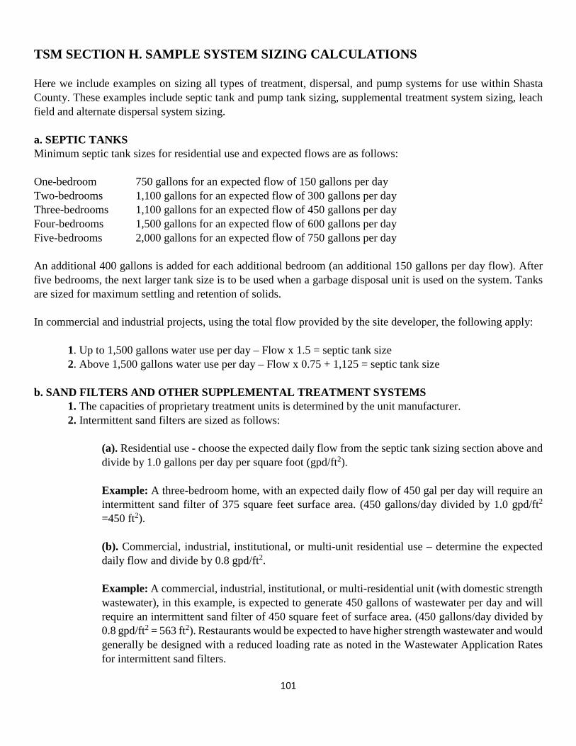
101
TSM SECTION H. SAMPLE SYSTEM SIZING CALCULATIONS Here we include examples on sizing all types of treatment, dispersal, and pump systems for use within Shasta County. These examples include septic tank and pump tank sizing, supplemental treatment system sizing, leach field and alternate dispersal system sizing. a. SEPTIC TANKS Minimum septic tank sizes for residential use and expected flows are as follows: One-bedroom 750 gallons for an expected flow of 150 gallons per day Two-bedrooms 1,100 gallons for an expected flow of 300 gallons per day Three-bedrooms 1,100 gallons for an expected flow of 450 gallons per day Four-bedrooms 1,500 gallons for an expected flow of 600 gallons per day Five-bedrooms 2,000 gallons for an expected flow of 750 gallons per day An additional 400 gallons is added for each additional bedroom (an additional 150 gallons per day flow). After five bedrooms, the next larger tank size is to be used when a garbage disposal unit is used on the system. Tanks are sized for maximum settling and retention of solids. In commercial and industrial projects, using the total flow provided by the site developer, the following apply:
1. Up to 1,500 gallons water use per day – Flow x 1.5 = septic tank size 2. Above 1,500 gallons water use per day – Flow x 0.75 + 1,125 = septic tank size
b. SAND FILTERS AND OTHER SUPPLEMENTAL TREATMENT SYSTEMS
1. The capacities of proprietary treatment units is determined by the unit manufacturer. 2. Intermittent sand filters are sized as follows:
(a). Residential use - choose the expected daily flow from the septic tank sizing section above and divide by 1.0 gallons per day per square foot (gpd/ft2).
Example: A three-bedroom home, with an expected daily flow of 450 gal per day will require an intermittent sand filter of 375 square feet surface area. (450 gallons/day divided by 1.0 gpd/ft2
=450 ft2). (b). Commercial, industrial, institutional, or multi-unit residential use – determine the expected daily flow and divide by 0.8 gpd/ft2.
Example: A commercial, industrial, institutional, or multi-residential unit (with domestic strength wastewater), in this example, is expected to generate 450 gallons of wastewater per day and will require an intermittent sand filter of 450 square feet of surface area. (450 gallons/day divided by 0.8 gpd/ft2 = 563 ft2). Restaurants would be expected to have higher strength wastewater and would generally be designed with a reduced loading rate as noted in the Wastewater Application Rates for intermittent sand filters.

102
3. Recirculating sand filters are sized as follows:
(a). Residential use – choose the expected daily flow from the septic tank sizing section above and divide by 5.0 gpd/ft2.
Example: A three-bedroom home, with an expected daily flow of 450 gallons per day will require a recirculating sand filter with 90 square feet of surface area. (450 gallons/day divided by 5.0 gpd/ft2 = 90 ft2).
(b). Commercial, industrial, institutional, and multi-residential use – determine the expected daily flow and divide by 4.0 gallons per day per square foot.
Example: A commercial, industrial, institutional, or multi-residential project (with residential strength wastewater) is expected to generate 450 gallons of wastewater per day and will require a recirculating sand filter of 113 square feet of surface area. (450 gallons per day divided by 4.0 gpd/ft2 = 112.5 square feet rounded up to 113). Restaurants with higher strength waste may require a lower loading rate as determined by a Qualified Professional.
The dispersal system chosen for use after treatment in a sand filter is sized per the instructions for that particular dispersal system.
c. PUMP TANKS Unless otherwise specified as part of a treatment or dispersal system design, a tank with an adequately-sized pump, used as a pump tank shall be a minimum of 500 gallons and equal to a minimum one day of expected daily wastewater flow or roughly one-third the size of the system septic tank. d. ROCK AND CHAMBERED LEACH LINES Leach fields are sized using TABLE 1 (based on the site soil percolation rate) in the appendices or calculated as a function of expected daily flow, soil loading rate (TABLE 2), and trench width/sidewall height for other uses.
1. Residential use - rock leach lines are sized using the applicable tables in the appendices.
Example: A three-bedroom house on a site with a percolation rate of 30 minutes per inch and a two foot wide trench with 12 inches of gravel under the pipe will require 211 lineal feet of leach line. However, if soils at the site will allow only a trench with 6 inches of rock under the pipe, multiply the 211 foot number by 1.25 to see that 264 lineal feet of leach line is required.
At the same site with a three (3) foot wide trench, and 12 inches of rock beneath the pipe, a total of 169 feet of leach line will be required. However, if soils at the site will only allow a trench with 6 inches of rock under the pipe, multiply the 169-foot number by 1.25 to see that 211 lineal feet of leach line is required.

103
2. Other uses – calculate the daily wastewater flow from the most recent version of the California Plumbing Code adopted by Shasta County or by some other means acceptable to the Director. Obtain a loading rate, based on percolation test results from TABLE 2 in the appendices.
Example: A motel with ten bed spaces (with kitchen) would generate an expected 60 gallons per bed space per day. The site has a percolation rate of 30 minutes per inch. The site would require a minimum of 281 lineal feet of leach line as follows:
At a site allowing 12 inches of leach rock under the pipe, the calculation is 60 gpd x 10 units divided by .533 g/ft2/day divided by 4 ft2/lineal foot =281 lineal feet. (From TABLE 2 in the appendices, a percolation rate of 30 minutes per inch equals a loading rate of 0.533 gallons per square foot per day).
The same site where soil depth will only allow 6 inches of rock under the pipe, the calculation is 60 gallons per day per bed space x 10 bed spaces divided by .533 g/ft2/day divided by 3 ft2/lineal foot = 375 lineal feet of leach line.
The calculation can also be similarly adjusted for a three-foot wide trench.
3. Chambered leaching systems – chambers are molded in a specific height, equivalent to 12 inches of rock beneath a leach pipe, and are typically labelled as equivalent to a 24 or 36 inch wide leach rock trench. Chambers may be substituted for a leach rock and pipe system. The calculations are identical to those examples shown above with 211 feet and 264 feet required in the first example (when chambers are installed shallow, where soils allow only 6 inch installation depth (i.e., Low Profile Chambers), additional fill cover is required and sidewall credit is given for 6 inches only).
e. SHALLOW PRESSURE DISTRIBUTION SYSTEMS Calculating leach line lengths is the same as those used to determine the amount of leach line required for a rock or chambered leach field as shown above. The depth of rock allowed beneath the pipe is the same for small diameter pressure lines as it is for 3 or 4 inch gravity flow lines. The calculation shall use a maximum of 4 feet of infiltrative area (bottom and sidewall) per lineal foot of trench. f. PRESSURE-DOSED SAND TRENCH (PDST) A PDST system is sized using trench bottom only. Based on site percolation rates, and using TABLE 2, a site proposed for a three-bedroom residence (450 gallons per day) with a percolation rate of 45 minutes per inch and either 12 or 24 inches of sand beneath the distribution rock leach piping in a 2 foot wide trench will require 726 lineal feet of PDST leach trench as follows:
450 gallons per day divided by a loading rate of 0.367 gallons per square foot per day (from TABLE 2) divided by 2 square feet per lineal foot (PDST systems are dosed based on bottom area only – sidewall is not included) = 613 lineal feet. A PDST system with a 3-foot wide trench would require 484 lineal feet of trench (450 divided by 0.367 divided by 3 = 409).
g. AT-GRADE SYSTEMS At-grade systems are constructed on the ground surface and, are therefore, sized using the bottom area of the infiltrative bed only. The sizing calculations are identical to those used in calculating the size of a PDST above.

104
The size of the fill area around the At-grade system is dependent on the size of the infiltrative area and is to be adjusted as required. Care must be taken to consider linear loading when designing an At-grade system as this may result in a narrower width infiltrative area. Sizing of an At-grade system is by trench bottom only. The residential sizing TABLE 1 is for two (2) feet of sidewall per lineal feet leach trench. With no credit given for sidewall in an at-grade system, you would need to double the length of leach trench in a two (2) foot wide at-grade system. As an option, and at the discretion of the Director, a three (3) foot wide trench may be allowed. Multiply the length of two (2) foot wide At-Grade dispersal system (as determined above) by two (2 foot wide trench) and divide by three (3 foot wide trench) to calculate the amount of three (3) foot wide trench required. For example:
1. A three-bedroom residence is proposed at a site with a percolation rate of 30 MPI. Using a two (2) foot wide trench, we find that from TABLE 1 that 215 feet of standard leach field is needed. However, no sidewall is used in the AT-grade system calculation so we multiply by two (2), arrive at two hundred and fifteen (215) feet X two (2) = four hundred and thirty (430) lineal feet of leach line needed.
2. If allowed at the site, using a three (3) foot wide trench, this would be reduced to two hundred and eighty seven feet (287) feet as follows – four hundred and thirty feet (430) X 2 feet wide divided by 3 foot wide = two hundred eighty seven (287) lineal feet of leach line.
h. MOUND SYSTEMS Mound system gravel distribution beds and sand basal areas are sized using bottom area only as follows: Gravel distribution beds are constructed within the sand basal area and are sized using only the bottom of the gravel distribution bed – no credit is given for sidewall. Loading rates of 1.0 gallons per square foot per day for individual residential use and 0.8 gallon per square foot per day for commercial, industrial, institutional, and multi-residential uses. The gravel distribution bed can be square for flat ground but must be rectangular for sloping ground, with the longest dimension parallel to the slope with a width of no more than 10 feet. Examples: At 450 gallons per day, a minimum distribution bed of 450 square feet (450 gallons per day divided by 1.0 gallons per square foot per day) is needed for residential use and a minimum 563 square feet (450 gallons per day divided by 0.8 gallon per square foot per day) is required for other uses. The minimum size of a mound system sand basal area is based on the size of the infiltrative area required to infiltrate the expected wastewater flow into the native soil, using loading rates from TABLE 2. The sand basal area includes: (1) the sum of the area directly beneath the gravel distribution bed, (2) the sand basal area extends 1 foot above and 2 feet below and adjacent to the distribution bed, and (3) that area needed, at a maximum 3 to 1 slope, to slope down to the native ground surface from the top of the sand. A sand basal area for a three-bedroom residence at a site with a loading rate (based on site soil percolation rate of 30 minutes per inch) of 0.533 gallons per square foot per day would be a minimum of 844 square feet. The same residence at a site with a percolation rate of 60 MPI (0.2 gallons per square foot per day loading rate) would

105
require a minimum basal area of 2250 square feet. The basal area calculation is the same for residential and other uses. Reminder – the sand basal area includes: 1. The area beneath the gravel distribution bed; 2. One foot upslope and 2 feet side and downslope from the distribution bed; and
3. The area required (at a maximum of 3 to 1 slope) to slope down from the top of the sand to the native ground surface. This last dimension will vary depending on sand depth and site slope. On sites greater than 2% slope, this area includes the sloping sand at the sides and downslope of the gravel distribution bed.
As a result of this, the required sand basal areas may be much larger than the dispersal bed area calculated above.
Care must be taken to consider linear loading when designing a mound system as this may result in a narrower and longer gravel distribution bed and sand basal area.
Finally, a continuous soil cover shall be placed over the entire gravel distribution bed and sand basal area. The soil cover shall have similar slope as the sand basal area and extend a minimum of three feet in all directions beyond the sand basal area.
i. DRIP DISPERSAL SYSTEMS Minimum size of the drip dispersal area shall be equal to the expected wastewater flow divided by the soil loading rate (determined by soil percolation tests). Example: A planned four-bedroom (600 gallons per day) home at a site with a percolation rate of 60 minutes per inch (a loading rate of 0.2 gallons per square foot per day) will require a minimum dispersal area of 3,000 square feet – 600 gallons per day divided by 0.2 gallons per square foot per day = 3,000 square feet of drip dispersal area needed. Example: Market with a wastewater flow of 450 gallons per day at a site with a percolation rate of 20 minutes per inch (0.657 gallons per square foot per day) will require a minimum dispersal area of 685 square feet – 450 gallons per day divided by 0.657 gallons per square foot per day = 685 square feet of drip dispersal area needed. Within each drip dispersal area, a drip emitter may be placed every two feet along a drip line and lines are spaced two feet apart. This means that each drip emitter is dosing 4.0 square feet of the drip dispersal area. To determine the number of emitters, divide the drip dispersal area by 4. Example: In the previous examples resulting in 3,000 and 685 square feet dispersal areas, the number of emitters required are 750 emitters (3,000 square feet divided by 1 emitter per 4 square feet = 750 emitters, and 171 emitters (685 square feet divided by 1 emitter per 4 square feet = 171 emitters).

106
With emitters spaced every 2 feet on a drip line, 750 emitters requires a minimum of 1,500 lineal feet of drip line (750 emitters x 2 lineal feet per emitter = 1,500 lineal feet) and 171 emitters requires a minimum of 342 lineal feet of drip line (171 emitters x 2 lineal feet per emitter = 342 lineal feet). f. PUMP SYSTEM SIZING The pump system shall be appropriate for sewage applications, shall be of the size and type to meet the hydraulic design requirements, and designed and constructed in accordance with this section.
1. The sump shall be a minimum one-third (1/3) the size of the septic tank. 2. The pump shall be sized for the design flow of the OWTS or OWTS component and provide the required GPM at the designed head. 3. Piping used with pump systems shall be of the appropriate strength and be sized for the pump output and flow requirements.

107
TSM SECTION I. INSPECTION FREQUENCY AND MAINTENANCE REQUIREMENT
This Section details the recommended frequency of inspections, the recommended minimum maintenance, the recommended system inspection requirements, and reporting to SCEHD and others for systems with supplemental treatment, alternate dispersal systems, and systems on steep slopes or systems with a curtain drain.
The majority of systems expected to be used in Shasta County will be standard Tier 1 systems or alternate Tier 2 systems that will not require supplemental treatment. The Environmental Health Division will have no formal requirement for inspections and/or maintenance for these systems.
I. TREATMENT
An onsite wastewater treatment system that includes supplemental treatment is required by the State OWTS Policy to have periodic monitoring and inspections. As a result, an Operating Permit will be issued by SCEHD after construction has been approved, for systems with supplemental treatment that includes specific minimum requirements for maintenance, inspections/monitoring, and reporting to SCEHD. The intent of this Operating Permit is to tailor the specific maintenance, inspection/monitoring, and reporting for that individual system. The frequency of maintenance, inspection/monitoring, and reporting by a person designated by the property owner will come from system component manufacturers, the owner’s consultant/system designer, and/or sewage disposal system contractor as will the minimum requirements.
II. DISPERSAL
Most of the alternate dispersal systems expected to be used in Shasta County have no moving parts to fail making an operating permit unnecessary. However, some of them will employ the use of pressure distribution to evenly dose a dispersal system. A pressure distribution system relies on a piping system that requires occasional flushing to prevent clogging. Siltation/solids settling within the distribution pipes results in clogging of the system orifices/emitters resulting in uneven distribution leading which can lead to premature failure of the system and expensive restoration. A system that uses pressure distribution as an integral process in the dispersal system would have a construction permit recorded with a note indicating the maintenance/monitoring requirements/frequencies. There may be other systems proposed for use in Shasta County that are not specifically included in the LAMP or Technical Standards Manual that may need an Operating Permit. In evaluating these proposed systems, the Director may impose specific maintenance, inspection/monitoring, or reporting requirements for that specific system.
III. INSPECTION FREQUENCY
The recommended frequency of inspections and general maintenance of dispersal systems will be specified in the individual OWTS construction permit. The frequency of required inspections, maintenance, monitoring, and reporting to SCEHD shall be specified in OWTS Operating Permits for systems with supplemental treatment.
IV. MINIMUM INSPECTION REQUIREMENTS
a. Septic Tanks. 1. Verify scum and sludge depths and recommend pumping frequency based on results. 2. Observe integrity of tank, including observations for:

108
3. cracks or indications of structural deterioration; 4. condition of inlet and outlet “T”
(a). condition of lids; (b). indication of leaks. (c). Observe the condition of outlet filters, if present.
b. Pump and Dosing Chamber. 1. Verify scum and sludge depths and recommend pumping frequency, as needed. 2. Observe integrity of tank, including observations for:
(a). cracks or indications of structural deterioration. (b). condition of inlet and outlet “T”. (c). condition of lids. (d). indication of leaks. (e). Observe condition of and correct operation of all floats.
(f). Verify all electrical cords are routed and harnessed per specifications. (g). Observe condition of pump inlet screens. (h). Verify pump cycle. (i). Verify any siphoning devices are functioning.
3. Control Panel.
(a). Verify timer and digital counter readings. (b). Verify cycles on digital counter. (c). Verify audible and visual alarms are functioning. (d). Verify that the run time is appropriate for the daily flow.
(e). Verify that the electrical box is free from moisture and all connections are secured. (f). Inspect other system components as per manufacturer’s maintenance specifications.
4. Dispersal Systems. (a). Verify maintenance and accessibility of any observation ports. (b). Measure effluent depth in any trench observation ports and wells.
(c). Ensure dispersal field is not obstructed by roads, structures, or vehicular traffic. (d). Ensure surface water drainage and/or downspouts are diverted away from dispersal field. (e). Inspect dispersal field and surrounding area for surfacing sewage. If observed, report to SCEHD within 48 hours of observation. Prevent effluent from running offsite or into bodies of water, submit repair permit application to SCEHD, and repair/correct as soon as possible. (f). For pressure distribution systems – observe condition of visible orifices and verify equal distribution to all laterals, where possible.
5. Curtain Drain. (a). Inspect curtain drain outlet for obstructions and vegetation removal.
(b). Inspect curtain drain area for excessive water and inspect associated dispersal field for surfacing sewage.
6. Sand Filters. (a). Inspect sand filter for surfacing effluent.
109
(b). Ensure dispersal field is not obstructed by roads, structures, and vehicular traffic. Ensure surface water drainage and/or downspouts are diverted away from dispersal field. (c). Verify maintenance and accessibility of any observation ports. (d). Verify uniform distribution of effluent in sand filter where possible. (e). Observe condition of visible orifices, if any. Verify integrity of lines as best as possible. (f). Verify pump chamber/dosing tank components are correct/functioning. (g). Inspect filter for damage/leakage at walls/liner where possible.
7. Other Aerobic treatment units. (a). Refer to manufacturer’s requirements. 8. Disinfection units. (a). Refer to manufacturer’s requirements.

110
TABLE 1 LINEAL FEET OF LEACH LINE FOR TRENCHES WITH 4 FT² OF ABSORPTION AREA¹
MPI Number of Bedrooms Additional
bedrooms add 1 2 3 4 5 6
1 100 100 100 125 160 190 35 2 100 100 100 125 160 190 35 3 100 100 100 125 160 190 35 4 100 100 100 125 160 190 35 5 100 100 100 125 160 190 35 6 100 100 145 190 235 285 50 7 100 100 145 190 235 285 50 8 100 100 145 190 235 285 50 9 100 100 145 190 235 285 50
10 100 100 145 190 235 285 50 11 100 100 145 195 240 290 50 12 100 100 150 195 245 295 50 13 100 100 150 200 250 300 50 14 100 105 155 205 255 305 55 15 100 105 155 210 260 310 55 16 100 110 160 215 265 320 55 17 100 110 165 215 270 325 55 18 100 110 165 220 275 330 55 19 100 115 170 225 280 340 60 20 100 115 175 230 290 345 60 21 100 120 175 235 295 350 60 22 100 120 180 240 300 360 60 23 100 125 185 245 310 370 65 24 100 125 190 250 315 375 65 25 100 130 195 255 320 385 65 26 100 130 195 260 325 390 65 27 100 135 200 265 335 400 70 28 100 135 205 270 340 405 70 29 100 140 210 280 345 415 70 30 100 145 215 285 355 425 75 31 100 145 220 290 360 435 75 32 100 150 225 295 370 445 75 33 100 150 225 300 375 450 75 34 100 155 235 310 385 465 80 35 100 160 240 315 395 475 80 36 100 165 245 325 405 485 85 37 100 165 250 330 415 495 85 38 100 170 255 340 425 510 85 39 100 175 260 350 435 520 90 40 100 180 270 360 445 535 90 41 100 185 275 365 460 550 95

111
TABLE 1 LINEAL FEET OF LEACH LINE FOR TRENCHES WITH 4 FT² OF ABSORPTION AREA¹
MPI Number of Bedrooms Additional
bedrooms add 1 2 3 4 5 6
42 100 190 285 375 470 565 95 43 100 195 290 390 485 580 100 44 100 200 300 400 500 600 100 45 105 205 310 410 515 615 105 46 110 215 320 425 530 635 110 47 110 220 330 435 545 655 110 48 115 225 340 450 565 675 115 49 120 235 350 465 585 700 120 50 125 245 365 485 605 725 125 51 125 250 375 500 625 750 125 52 130 260 390 520 650 780 130 53 135 270 405 540 675 810 135 54 145 285 425 565 705 845 145 55 150 295 440 590 735 880 150 56 155 310 460 615 770 920 155 57 165 325 485 645 805 965 165 58 170 340 505 675 845 1010 170 59 180 355 535 710 885 1065 180 60 190 375 565 750 940 1125 190 61 195 385 575 765 955 1145 195 62 195 390 580 775 970 1160 195 63 200 395 595 790 990 1185 200 64 205 405 605 805 1005 1205 205 65 205 410 615 820 1020 1225 205 66 210 420 625 835 1045 1250 210 67 215 425 640 850 1060 1275 215 68 220 435 650 865 1080 1295 220 69 225 445 665 885 1105 1325 225 70 225 450 675 900 1125 1350 225 71 230 460 690 915 1145 1375 230 72 235 470 705 940 1175 1410 235 73 240 480 720 960 1195 1435 240 74 245 490 735 975 1220 1465 245 75 250 500 750 1000 1250 1500 250 76 260 515 770 1025 1280 1535 260 77 265 525 785 1045 1305 1565 265 78 270 540 805 1075 1340 1610 270 79 275 550 825 1095 1370 1645 275 80 285 565 850 1130 1410 1695 285 81 290 580 870 1155 1445 1735 290 82 300 595 890 1185 1480 1775 300 83 305 610 915 1220 1525 1830 305

112
TABLE 1 LINEAL FEET OF LEACH LINE FOR TRENCHES WITH 4 FT² OF ABSORPTION AREA¹
MPI Number of Bedrooms Additional
bedrooms add 1 2 3 4 5 6
84 315 625 940 1250 1565 1875 315 85 325 645 965 1285 1605 1925 325 86 335 665 1000 1330 1660 1995 335 87 345 685 1025 1365 1705 2050 345 88 355 705 1055 1405 1755 2105 355 89 365 730 1095 1460 1825 2185 365
90 - 120 375 750 1125 1500 1875 2250 375
¹ Lineal footage of leach line for trenches that provide four square feet (4 FT²) of absorption area per lineal foot (i.e. trenches two feet wide with one foot gravel, trenches three feet wide with one half of one foot of gravel, etc.).

113
TABLE 2 APPLICATION RATES AS DETERMINED FROM STABILIZED PERCOLATION RATE
Percolation Rate
(MPI)
Application Rate
(gpd/ft²)
Percolation Rate
(MPI)
Application Rate
(gpd/ft²)
Percolation Rate
(MPI)
Application Rate
(gpd/ft²)
1 1.2 31 0.522 61 0.197
2 1.2 32 0.511 62 0.194 3 1.2 33 0.5 63 0.19 4 1.2 34 0.489 64 0.187 5 1.2 35 0.478 65 0.184 6 0.8 36 0.467 66 0.18 7 0.8 37 0.456 67 0.177 8 0.8 38 0.445 68 0.174 9 0.8 39 0.434 69 0.17 10 0.8 40 0.422 70 0.167 11 0.786 41 0.411 71 0.164 12 0.771 42 0.4 72 0.16 13 0.757 43 0.389 73 0.157 14 0.743 44 0.378 74 0.154 15 0.729 45 0.367 75 0.15 16 0.714 46 0.356 76 0.147 17 0.7 47 0.345 77 0.144 18 0.686 48 0.334 78 0.14 19 0.671 49 0.323 79 0.137 20 0.657 50 0.311 80 0.133 21 0.643 51 0.3 81 0.13 22 0.629 52 0.289 82 0.127 23 0.614 53 0.278 83 0.123 24 0.6 54 0.267 84 0.12 25 0.589 55 0.256 85 0.117 26 0.578 56 0.245 86 0.113 27 0.567 57 0.234 87 0.11 28 0.556 58 0.223 88 0.107 29 0.545 59 0.212 89 0.103 30 0.533 60 0.2 90 - 120 0.1

114
SEPTIC TANK AND DISPERSAL SYSTEM SETBACKS. This table is to be used to determine appropriate setbacks for septic tanks and dispersal systems. The term septic tank, as used here, also includes sumps and supplemental treatment systems.
TABLE 3 REQUIRED HORIZONTAL SETBACK DISTANCES
Minimum Horizontal Distance (in feet) Required Between:
Building
Sewer
Septic
Tank
Dispersal
Field
Well
Building or Structures1 2 5 8 None
Property Lines None 5 10 5
Private/ Public Wells 502 50 100/1503 None
Domestic Water Line 54 5 5 None
Springs5
50
50
200
Above
Flood
Plain
Ephemeral Drainage6
50
50
50
Above
Flood
Plain
Intermittent and
Perennial Streams7
50
50
100
Above Flood
Plain
Lakes8
50
50
200
Above
Flood
Plain
Cuts or Excavations Four times height of cut with a maximum of 50 feet
None
Dispersal Field 5 10 100
Distribution Box 5 100

115
FOOTNOTES:
1. Includes mobile homes, porches and steps, whether covered or uncovered, breezeways, roofed porte-cocheres, roofed patios, carports, covered walks, covered driveways and other structures or appurtenances.
2. All non-metallic drainage piping shall clear domestic water supply wells at least 50 feet. This distance may be reduced to not less than 25 feet when approved piping is installed. Where special hazards are involved, the distance required shall be increased as necessary pursuant to the Director of Environmental Health.
3. Wastewater effluent dispersal systems shall be at least 100 feet from private domestic wells and 150 feet from public water supply wells.
4. Water pipes and sewer pipes shall not be located in the same trench. The minimum separation shall be ten feet.
5. These distances apply to sewage disposal systems on the same level as or lower than any spring. Sewage disposal systems shall not be closer than 200 feet at any point in relationship to a spring located on the same hillside or in the same watershed or 100 feet if downhill from the spring.
6. Ephemeral drainage also includes roadside ditches.
7. Includes irrigation ditches, roadside ditches, and natural and artificial drainage ways with either intermittent or continuous flows. This distance is to be measured from the 10-year flood line or top of bank or other evident high-water line or the expected 10-year flood line.
8. Includes lakes, ponds, reservoirs, and other bodies of standing water, as measured from the high-water line or spillway elevation. For lakes that are uphill from the disposal field, the setback may be reduced to 100 feet.
The Director may accept horizontal setbacks that vary from the required distances above. Examples would include drainage ways that were constructed as part of road construction but carry little or no water or reduced setbacks from systems that utilize supplemental treatment and/or disinfection.