shaping, planing and slotting operations v/me... · machine tool used for shaping operation is...
TRANSCRIPT
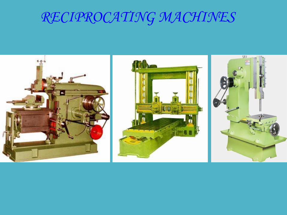
RECIPROCATING MACHINES
Shaping, planning and slotting can be defined as the
process of removing metal from a surface in horizontal,
vertical and inclined position to produce a flat or plane
surface, slots and grooves by means of a relative
reciprocating motion between the tool and work piece.

Difference between the three processes of shaping,
planing and slotting is that in shaping and slotting, the
tool is reciprocating and the work piece is fed in to the
cutting tool while in planning, the work piece is
reciprocating and the tool is fed in.

Tool reciprocates horizontally in the shaping and
vertically in slotting.
Cutting is intermittent in all the three processes
because in the relative reciprocating motion the tool
cuts only in forward- working (or cutting) stroke
followed by the idle-return stroke.


The Shaper
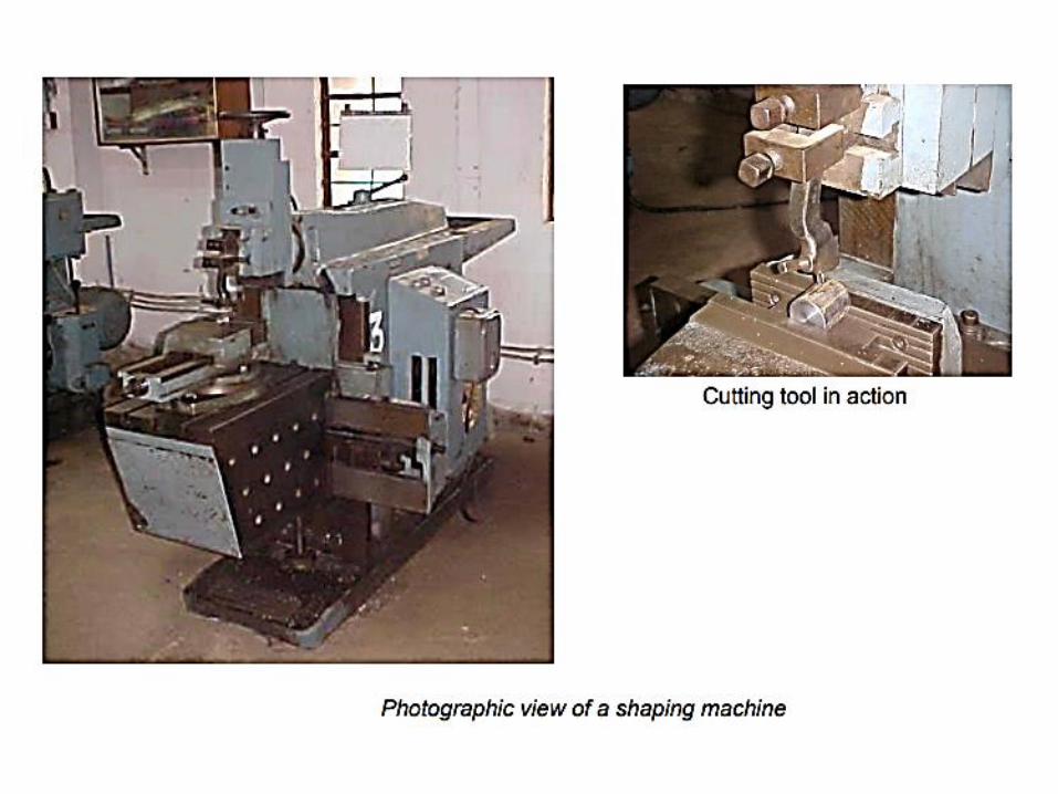
Machine tool used for shaping operation is called shaper.
Designed for machining flat surfaces on small sized jobs. If the
size of the job is large, then planing is used.
In a shaper , the work piece is held stationary during cutting,
while the tool reciprocates horizontally. the feed and depth of
cut are normally provided by moving the work. Such shaper is
called a horizontal shaper.
Shaper is a machine tool used primarily for:
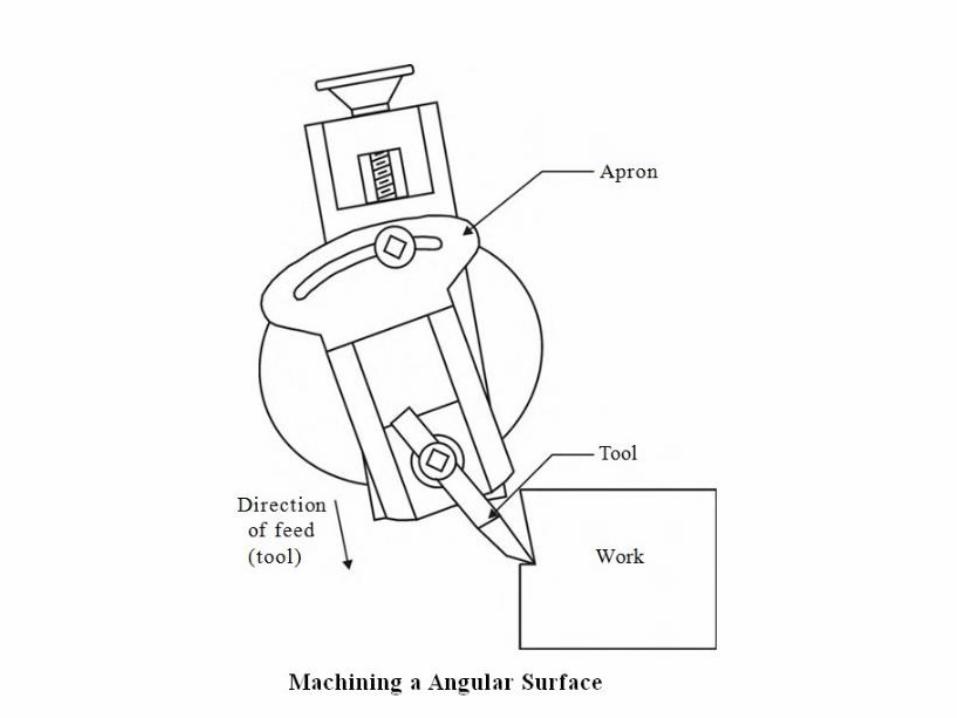
1. Producing a flat or plane surface which may be in
a horizontal, a vertical or an angular plane.
2. Making slots, grooves and keyways
3. Producing contour of concave/convex or a
combination of these
Working Principle:
• Job is rigidly fixed on the machine table.
• Single point cutting tool held properly in the tool
post is mounted on a reciprocating ram.
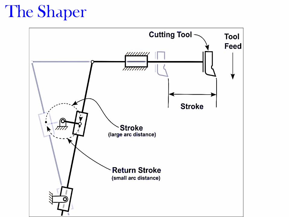
• Reciprocating motion of the ram is obtained by a
quick return motion mechanism.
• As the ram reciprocates, the tool cuts the material
during its forward stroke.
• During return, there is no cutting action and this
stroke is called the idle stroke.
• Forward and return strokes constitute one operating
cycle of the shaper.

SHAPER

Construction:
The main parts of the Shaper machine is
Base
Body (Pillar, Frame, Column)
Cross rail, Ram
tool head (Tool Post, Tool Slide, Clamper Box Block)

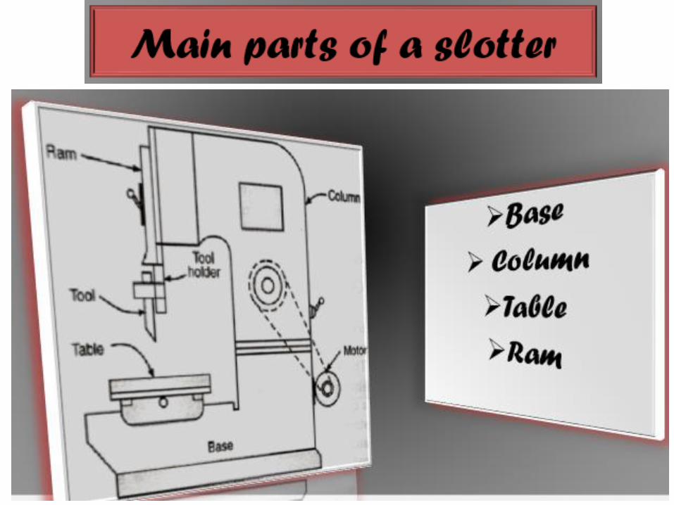
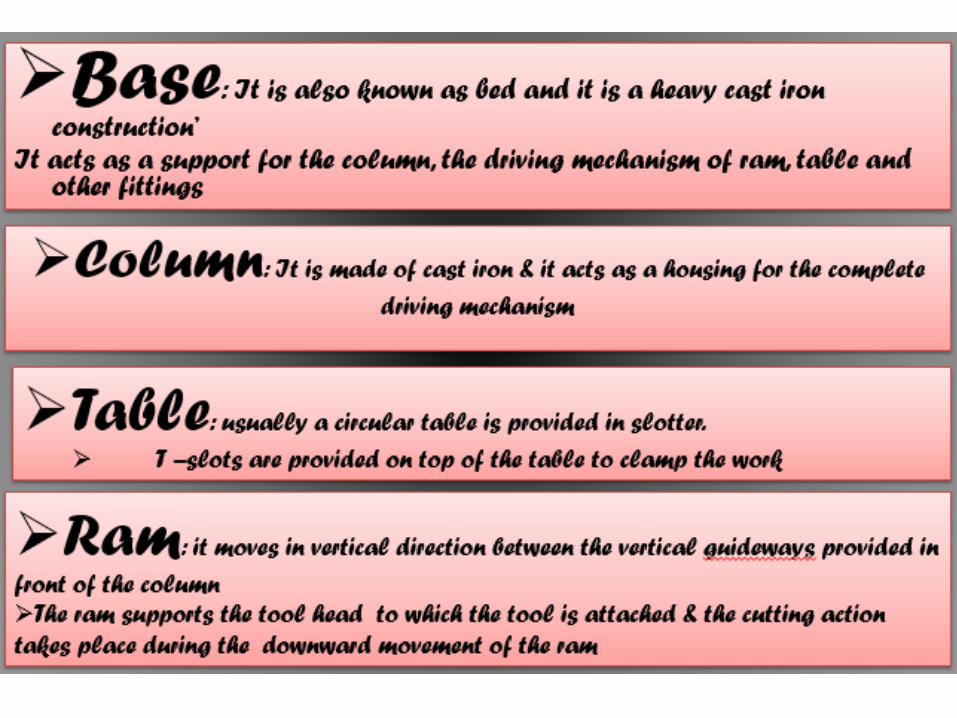
Base:
• Base is a heavy cast iron casting which is fixed to the shop
floor.
• It supports the body frame and the entire load of the
machine.
• Base absorbs and withstands vibrations and other forces
which are likely to be induced during the shaping
operations.
Body (Pillar, Frame, Column):
• It is mounted on the base and houses the drive mechanism
compressing the main drives, the gear box and the quick
return mechanism for the ram movement.
• The top of the body provides guide ways for the ram and its
front provides the guide ways for the cross rail.
Cross rail:
• Mounted on the front of the body frame and can be
moved up and down.
• The vertical movement of the cross rail permits jobs
of different heights to be accommodated below the
tool.
• Sliding along the cross rail is a saddle which carries
the work table.
Ram and tool head:
• Ram is driven back and forth in its slides by the
slotted link mechanism.
• The back and forth movement of ram is called
stroke and it can be adjusted according to the length
of the workpiece to be-machined.

Types of Shaping Machines
Shaping machines are the reciprocating type of machine
tools in which the work piece is held stationary and the
tool reciprocates.
Most shapers have reciprocating motion in horizontal
position (horizontal shapers) but shapers are also designed
with reciprocating motion in vertical position (vertical
shapers) or slotting machines or slotters.

The Shaping Operation

Quick Return Mechanism
Ram moves at a comparatively slower speed
during the forward cutting stroke.
During the return stroke, the mechanism is so designed
to make the tool move at a faster rate to reduce the idle
return time.
This mechanism is known as quick return mechanism.

As the ram moves at a faster rate during return stroke,
the time taken becomes less. The total machining time
decreases and the rate of production increases. The
following mechanisms are used for quick return of the
ram.
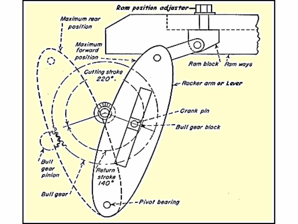
1.Crank and slotted link mechanism
2.Hydraulic mechanism
3.Whitworth mechanism
The Shaper


Strokelength of a ram is the distance the ram moves forward or
backward. It depends upon the distance between the centre of the bull
gear and the centre of the sliding block. it is adjusted according to the
length of the work.
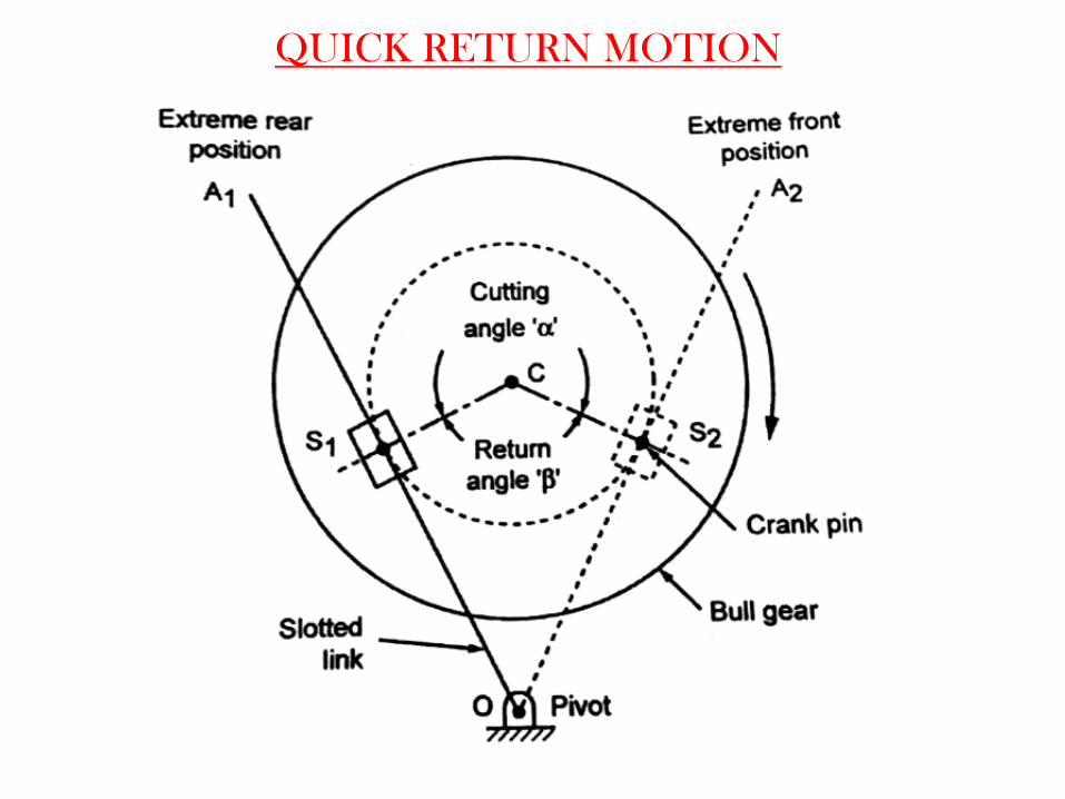
QUICK RETURN MOTION
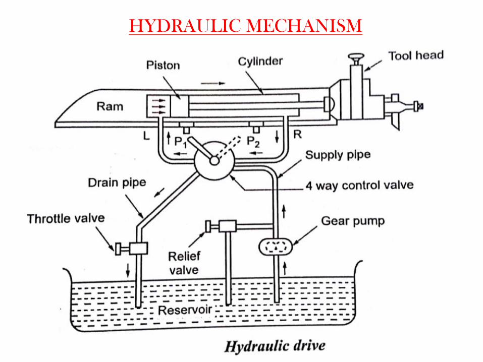
HYDRAULIC MECHANISM

WHITWORTH QUICK RETURN MECHANISM
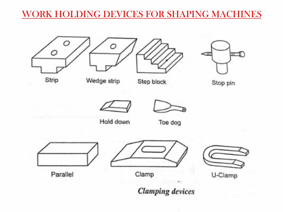
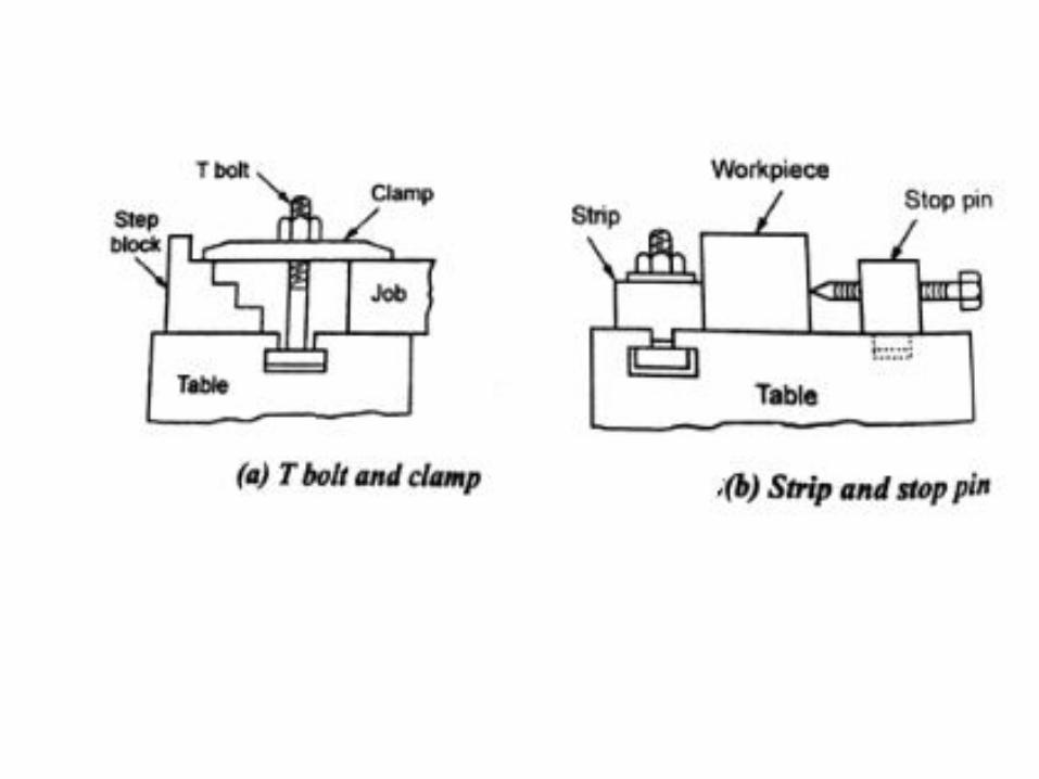
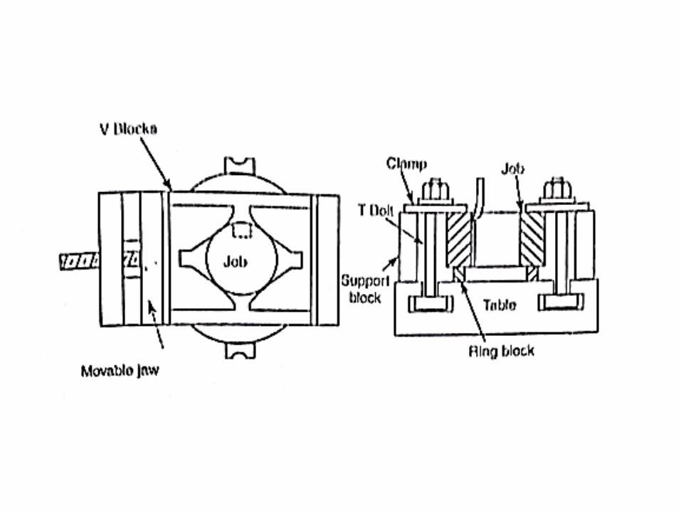
WORK HOLDING DEVICES FOR SHAPING MACHINES
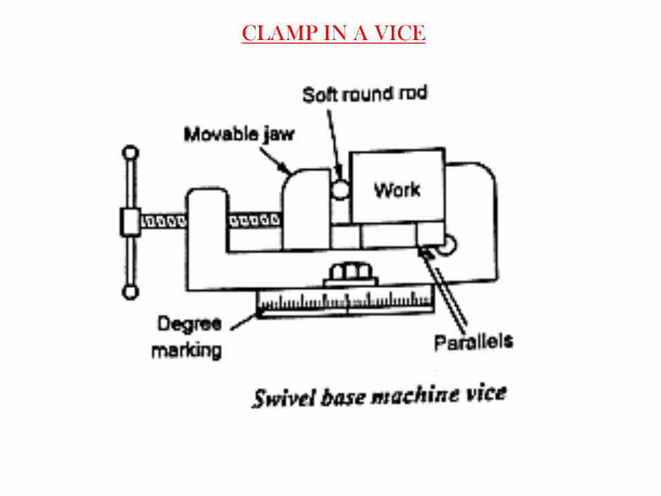
CLAMP IN A VICE

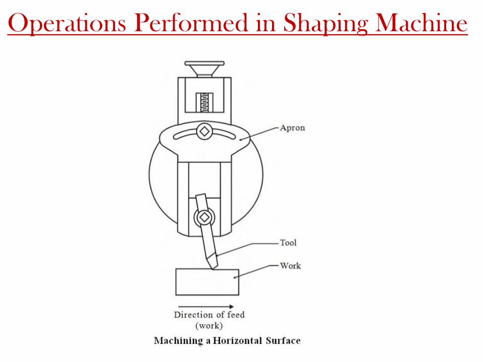
Operations Performed in Shaping Machine
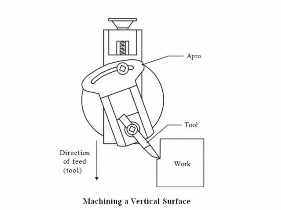


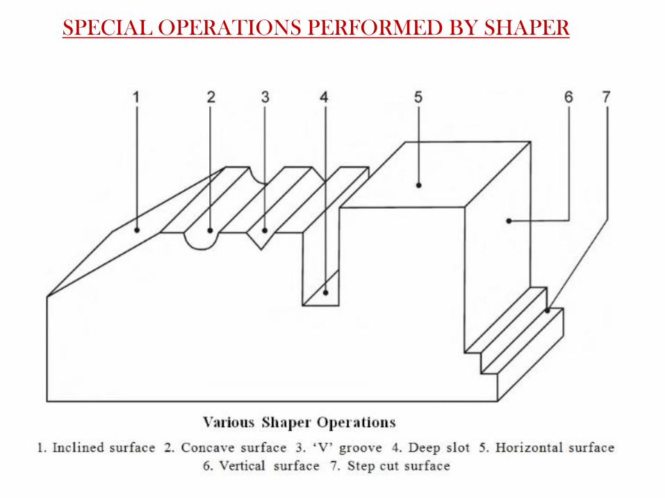
SPECIAL OPERATIONS PERFORMED BY SHAPER
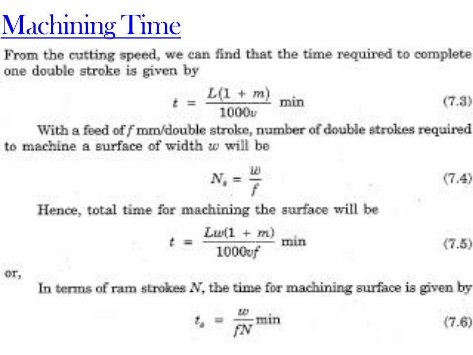
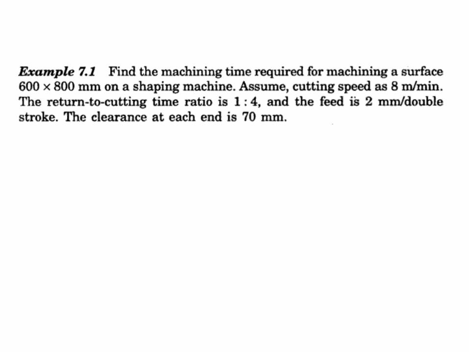
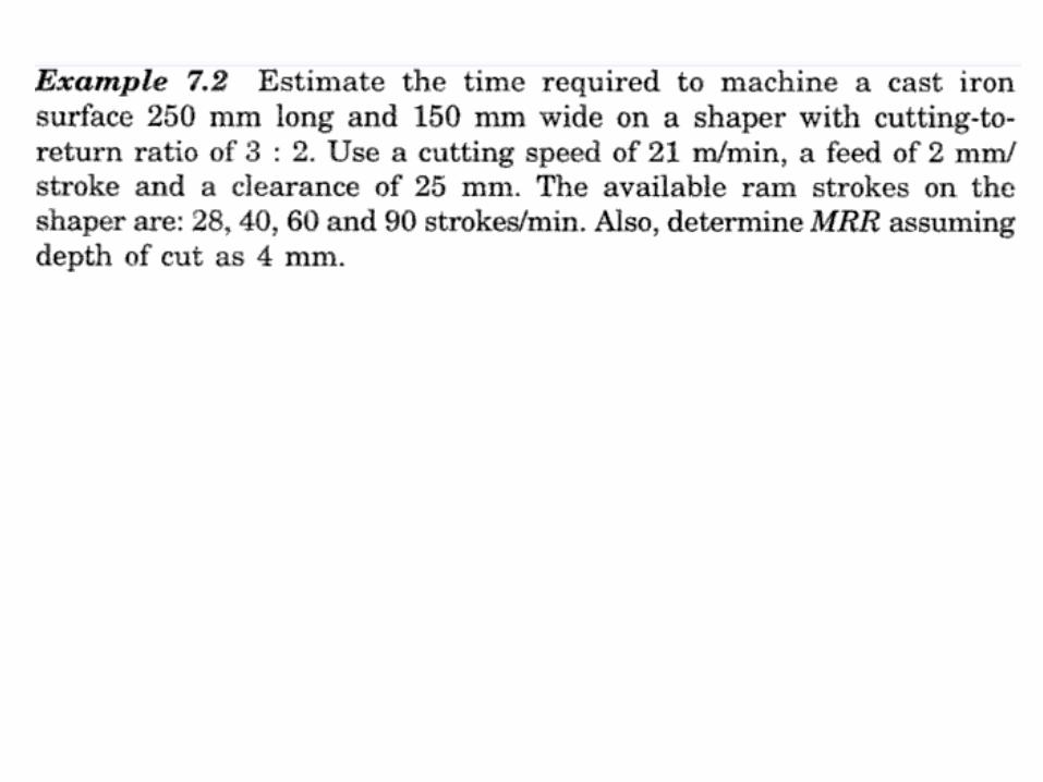
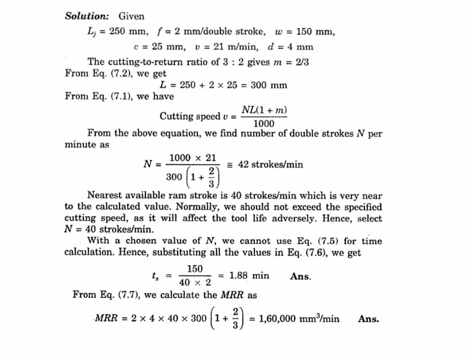
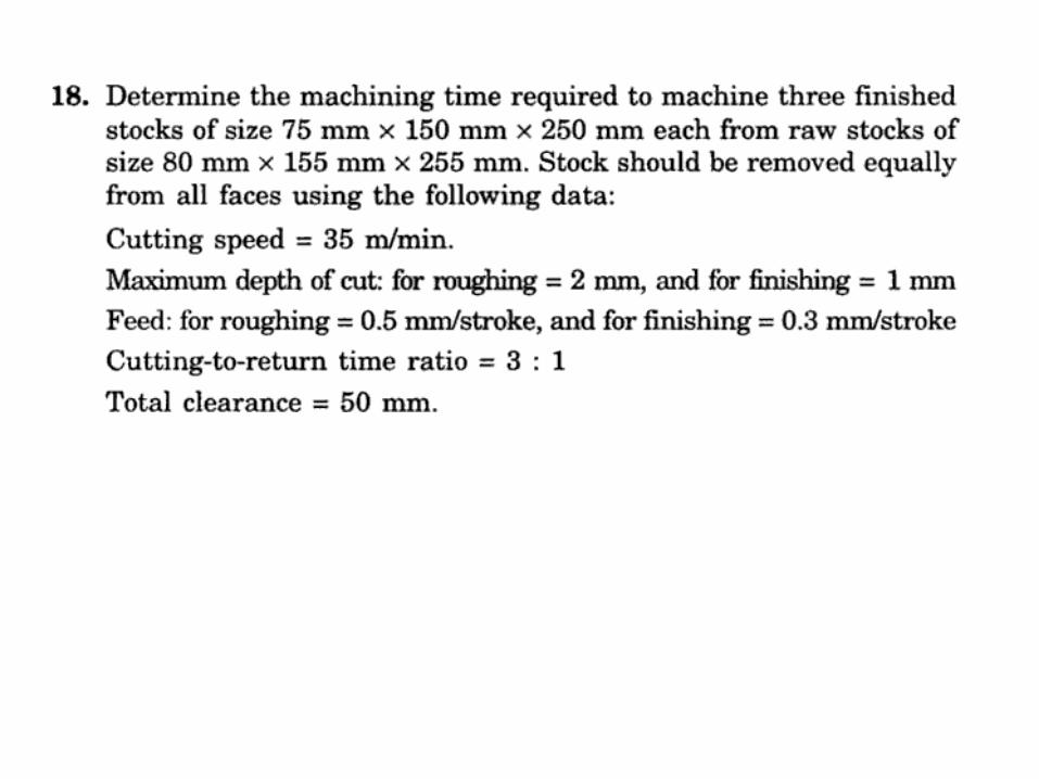
Machining Time

Material removal rate

The Planer
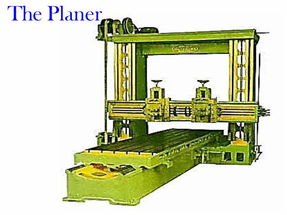
The Planer
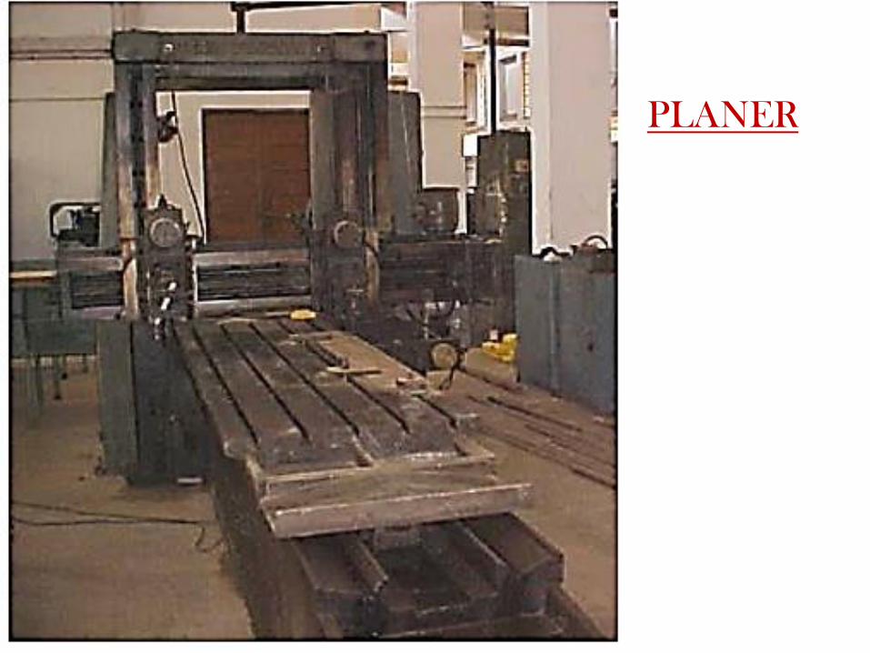
PLANER
Planer Planer or planing machine is a machine tool, which like the
shaper produces flat surfaces in horizontal, vertical or inclined
plane.
Fundamental difference is that the planer operates with an
action opposite to that of the shapers, i.e., the work piece
reciprocates past one or mare stationary single point cutting
tools.
Planers are meant for machining large sized work pieces, which
cannot be machined by the shapingmachines.

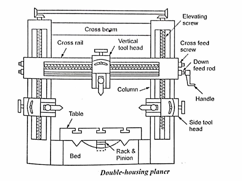
Types of Planing Machines
Double housing planer
Open side planer
Pit planer
Edge planer
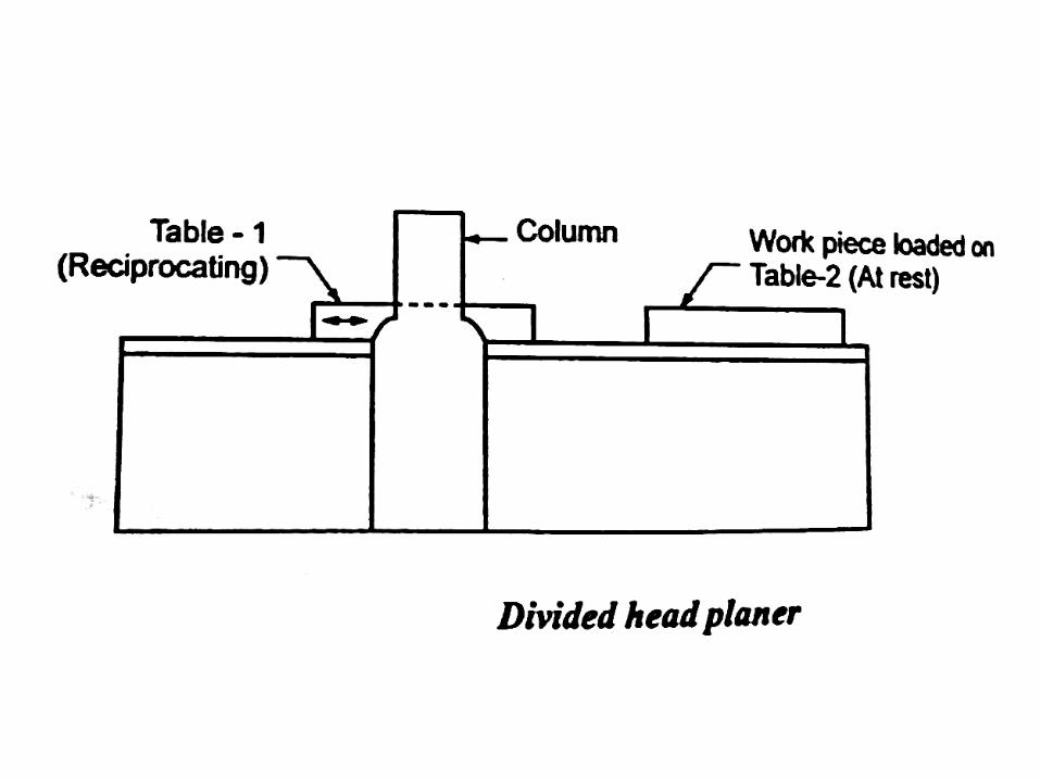
Divided head planer


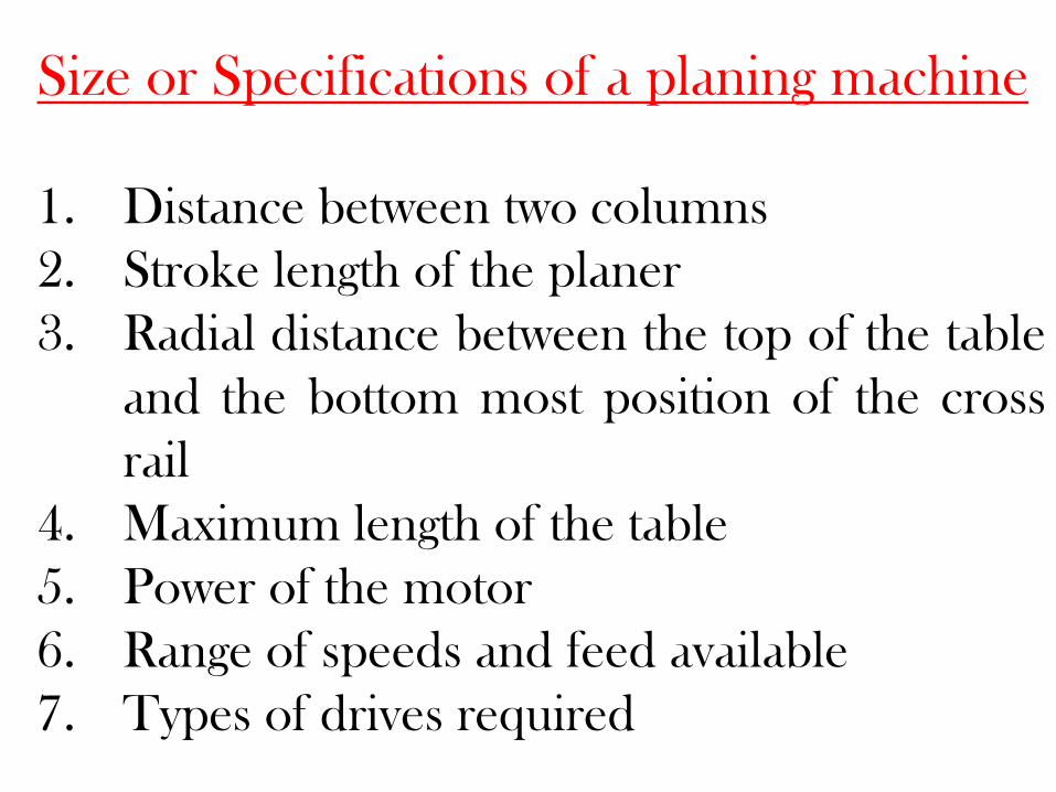
Size or Specifications of a planing machine
1. Distance between two columns
2. Stroke length of the planer
3. Radial distance between the top of the table
and the bottom most position of the cross
rail
4. Maximum length of the table
5. Power of the motor
6. Range of speeds and feed available
7. Types of drives required
WORK HOLDING DEVICES IN PLANING MACHINES
Following clamping devices are used
• Angle plate
• Planer jacks
• Stop block
• Adjustable screw stop

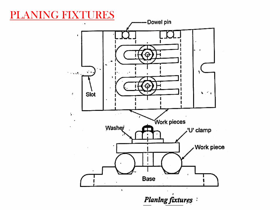
PLANING FIXTURES


OPERATIONS PERFORMED ON
PLANING MACHINES
• Planing horizontal surface
• Planing of an angle
• Planing vertical surface
• Planing curved surface
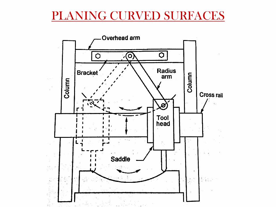
PLANING CURVED SURFACES

OPEN AND CROSS BELT DRIVE

ELECTRIC DRIVE
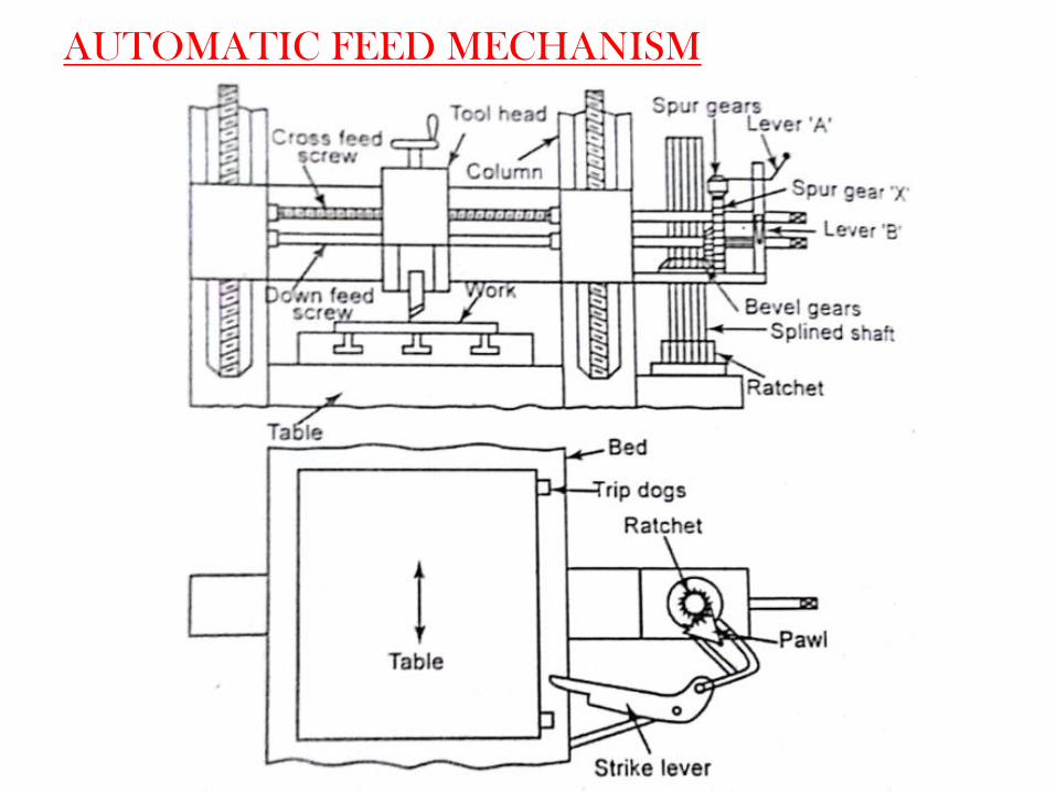
AUTOMATIC FEED MECHANISM

Size of shaper and planers
The size of planer and shaper are specified
by the maximum length of stroke.
The normal maximum stroke length of the
stroke is 800mm.
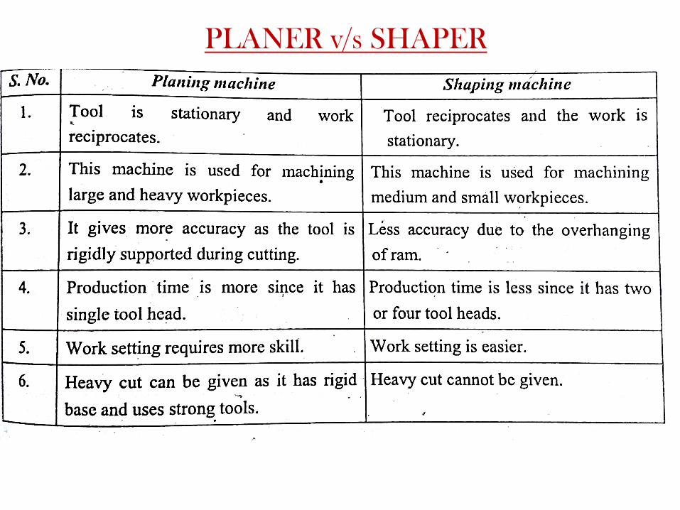
PLANER v/s SHAPER

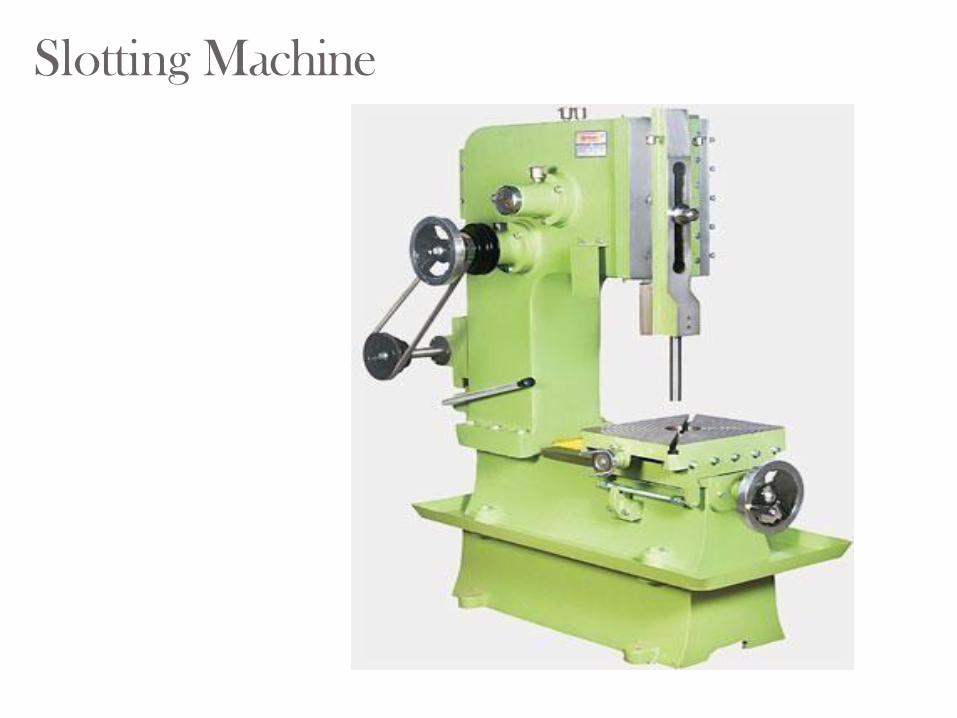
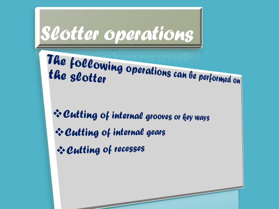
Slotting Machine


Slotter drive mechanisms
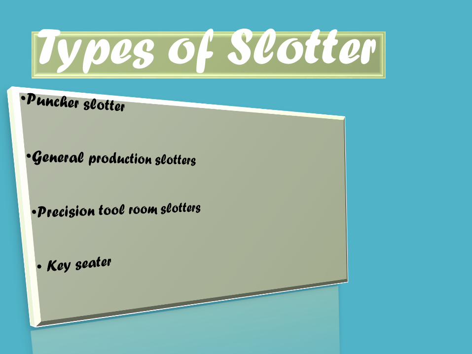
Types of Slotter

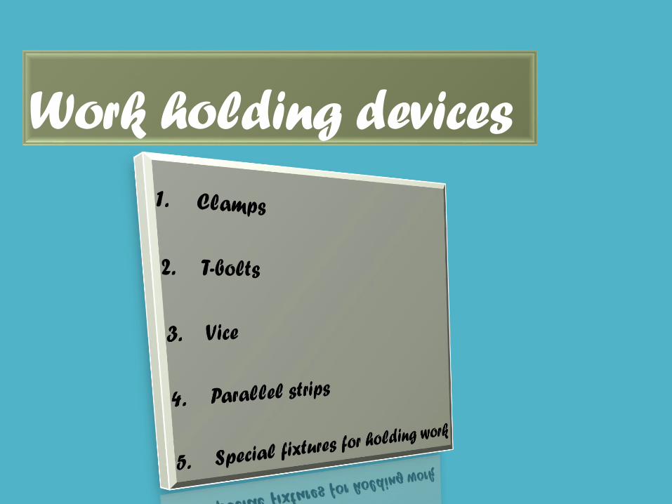
Work holding devices


FEED MECHANISM


19. The 400mmX250mm face of cast iron block of
size 400mmX250mmX 100mm is to be rough
machined using HSS tool on a conventional crank
shaper. Estimate the machining time assuming an
average cutting speed of 20m/min and a feed of
0.2 mm/stroke. The cutting time to return time ratio
is given to be 1.5 and the ram cycles available on
the shapers are 28,40,60 and 90 per minute. Ans:
choosing 28 strokes/min, time=44.65min