shape optimization of free-form shells using invariants of
TRANSCRIPT
*Currently, Kanebako Structural Engineers; E-mail: [email protected] **Currently, Dept. of Architecture, Graduate School of Engineering, Hiroshima University; E-mail: [email protected]
Shape Optimization of Free-form Shells Using Invariants of Parametric Surface
Shinnosuke Fujita1 and Makoto Ohsaki2
1Graduate Student, Department of Architecture and Architectural Engineering,
Kyoto University, Japan* 2Associate Professor, Department of Architecture and Architectural Engineering,
Kyoto University, Japan**
Abstract: A new approach is proposed for shape optimization of shells, where the require-ments on geometrical properties, constructability, and mechanical performance are simulta-neously considered in the problem formulation. The surface shape is modeled using a trian-gular Bézier patch to reduce the number of design variables, while the ability of generating moderately complex shape is maintained. The strain energy under specified loading condition is used to represent the mechanical performance, and the geometrical properties are quantita-tively defined using algebraic invariants of the parametric surface. The developable surface that has high constructability is generated by assigning an appropriate constraint on an alge-braic invariant. The effectiveness of the proposed approach is demonstrated through several numerical examples, and the characteristics of the optimal shapes under various constraints are discussed. Keywords: shape optimization; nonlinear programming; sensitivity analysis; triangular Bézier patch; algebraic invariant
1. INTRODUCTION Advances of computer technologies as well as the developments of structural materials and construc-tion methods have enabled us to design long-span shell roofs with complex shapes and topologies that cannot be categorized into traditional regular shapes. Such shapes are described using parametric surfaces, e.g., Bézier surface and non-uniform rational B-spline (NURBS) surface [1], which are de-veloped in the field of computer-aided geometric design (CAGD) [2]. Complex surfaces defined us-ing the parametric surfaces are often called free-form surface [3]. The shapes of shell roofs can also be defined using parametric surfaces [4], and such shells are called free-form shells [5].
Using a parametric surface, the number of design variables can be reduced, while the ability of generating moderately complex shape is maintained. Therefore, the parametric representation is ef-

fectively used for shape optimization of surfaces, which has been mainly developed in the fields of mechanical engineering and aeronautical engineering [6]. For application to spatial structures, shape optimization of shell roofs has been extensively studied since 1990s. Ramm et al. [4] optimized shapes of shells under buckling constraints, where Bézier surface is used for modeling the surface. However, in those studies, the performance measures that are important in the field of architectural engineering are not considered.
One of the important aspects in design of shell roofs is that their shapes are basically designed based on the preference and experience of the architects and structural designers. It may be possible for the designer to assign the most desired shape explicitly. However, the mechanical behavior of a shell with non-regular shape is complicated, and it is very difficult for an architect to decide a feasi-ble shape of a real-world structure based on his/her experience and intuition. Furthermore, some constraints are given for local geometrical properties such as height, slope, and curvature based on requirements in architectural planning, constructability, reduction of wind and snow loads, etc. Therefore, it is desirable that the surface shape is defined parametrically, and the optimal shape is found in view of a compromise between geometrical property and mechanical rationality. In this process, it will be helpful if the local shapes such as cylindrical and spherical shapes can be assigned quantitatively in the formulation of optimization problem.
It should also be noted that simple application of structural shape optimization to shell roofs may result in a complex shape with large curvature, non-monotonic variation of gradients, etc. In this re-spect, qualitative measures for defining fairness such as roundness and planeness may be effectively utilized [7]. Ohsaki et al. [8] presented a shape optimization approach for latticed shells defined us-ing a triangular Bézier patch. Ohsaki and Hayashi [9] defined a roundness metric for shape optimiza-tion of ribbed shells. Ohsaki et al. [10] developed a multiobjective programming approach to design of round arches and shells based on direct assignment of the center of curvature. However, in these approaches, only global properties can be controlled, although there are local measures of geometry to be considered by the designers.
The authors developed a new approach to shape optimization of shells modeled using Bézier surface [11]. The strain energy is used to represent the mechanical performance, and the local geo-metrical characteristics are quantified by algebraic invariants of the surface representing curvature, convexity, gradient, etc. The requirement for developability of the surface is incorporated as the con-straints on the principal curvature. However, the effectiveness of the approach was not fully appre-ciated, because the tensor product Bézier surface was used for a shell with rectangular plan.
In this paper, we extend the authors’ approach to utilize triangular Bézier patches that can model a shell with irregular plan. A new invariant is presented for the roundness of the surface. A multiob-jective programming problem is solved using the constraint approach to generate a set of Pareto op-timal solutions as a trade-off between mechanical efficiency and roundness. The effectiveness of the proposed approach is demonstrated through several numerical examples, and the characteristics of the optimal shapes under various constraints are discussed.
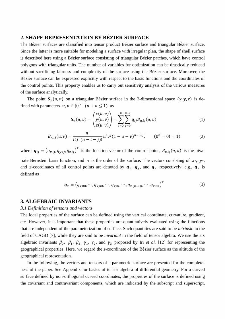
2. SHAPE REPRESENTATION BY BÉZIER SURFACE The Bézier surfaces are classified into tensor product Bézier surface and triangular Bézier surface. Since the latter is more suitable for modeling a surface with irregular plan, the shape of shell surface is described here using a Bézier surface consisting of triangular Bézier patches, which have control polygons with triangular units. The number of variables for optimization can be drastically reduced without sacrificing fairness and complexity of the surface using the Bézier surface. Moreover, the Bézier surface can be expressed explicitly with respect to the basis functions and the coordinates of the control points. This property enables us to carry out sensitivity analysis of the various measures of the surface analytically.
The point , on a triangular Bezier surface in the 3-dimensional space , , is de-fined with parameters , 0,1 1 as
,,,,
, , (1)
, ,!
! ! ! 1 , 0 0! 1 (2)
where , , , , ,T is the location vector of the control point, , , is the biva-
riate Bernstein basis function, and is the order of the surface. The vectors consisting of -, -, and -coordinates of all control points are denoted by , , and , respectively; e.g., is defined as
, , , , , , , , , , , , ,T (3)
3. ALGEBRAIC INVARIANTS 3.1 Definition of tensors and vectors The local properties of the surface can be defined using the vertical coordinate, curvature, gradient, etc. However, it is important that these properties are quantitatively evaluated using the functions that are independent of the parameterization of surface. Such quantities are said to be intrinsic in the field of CAGD [7], while they are said to be invariant in the field of tensor algebra. We use the six algebraic invariants , , , , , and proposed by Iri et al. [12] for representing the geographical properties. Here, we regard the z-coordinate of the Bezier surface as the altitude of the geographical representation.
In the following, the vectors and tensors of a parametric surface are presented for the complete-ness of the paper. See Appendix for basics of tensor algebra of differential geometry. For a curved surface defined by non-orthogonal curved coordinates, the properties of the surface is defined using the covariant and contravariant components, which are indicated by the subscript and superscript,
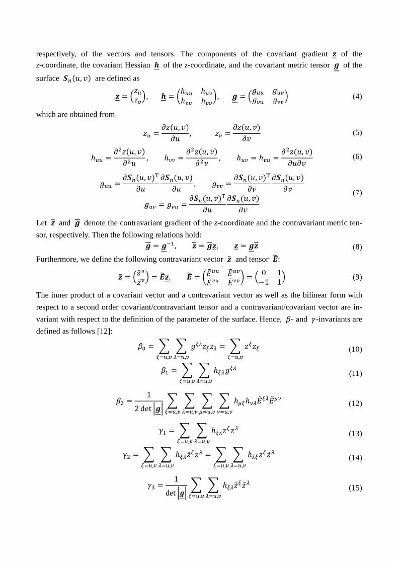
respectively, of the vectors and tensors. The components of the covariant gradient of the z-coordinate, the covariant Hessian of the z-coordinate, and the covariant metric tensor of the
surface , are defined as
, , (4)
which are obtained from
,,
, (5)
,,
,,
, (6)
, T ,,
, T ,
, T , (7)
Let and denote the contravariant gradient of the z-coordinate and the contravariant metric ten-sor, respectively. Then the following relations hold: , , (8) Furthermore, we define the following contravariant vector and tensor :
, 0 1
1 1 (9)
The inner product of a covariant vector and a contravariant vector as well as the bilinear form with respect to a second order covariant/contravariant tensor and a contravariant/covariant vector are in-variant with respect to the definition of the parameter of the surface. Hence, - and -invariants are defined as follows [12]:
,,,
(10)
,,
(11)
1
2 det ,,,,
(12)
,,
(13)
γ ,,,,
(14)
1
det
,,
(15)
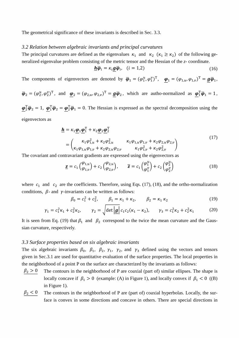
The geometrical significance of these invariants is described in Sec. 3.3. 3.2 Relation between algebraic invariants and principal curvatures The principal curvatures are defined as the eigenvalues and of the following ge-neralized eigenvalue problem consisting of the metric tensor and the Hessian of the z- coordinate. , 1,2 (16)
The components of eigenvectors are denoted by , T , , , ,T ,
, T , and , , ,T , which are autho-normalized as T 1 ,
T 1, T T 0. The Hessian is expressed as the spectral decomposition using the
eigenvectors as
T T
, , , , , ,
, , , , , ,
(17)
The covariant and contravariant gradients are expressed using the eigenvectors as
,,
,,
, (18)
where and are the coefficients. Therefore, using Eqs. (17), (18), and the ortho-normalization conditions, - and -invariants can be written as follows: , , (19)
, det , (20)
It is seen from Eq. (19) that and correspond to the twice the mean curvature and the Gaus-sian curvature, respectively. 3.3 Surface properties based on six algebraic invariants The six algebraic invariants , , , , , and defined using the vectors and tensors given in Sec.3.1 are used for quantitative evaluation of the surface properties. The local properties in the neighborhood of a point P on the surface are characterized by the invariants as follows:
0 The contours in the neighborhood of P are coaxial (part of) similar ellipses. The shape is locally concave if 0 (example: (A) in Figure 1), and locally convex if 0 ((B) in Figure 1).
0 The contours in the neighborhood of P are (part of) coaxial hyperbolas. Locally, the sur-face is convex in some directions and concave in others. There are special directions in

which the contour lines are straight ((C) in Figure 1). 0 One of the principal curvatures is 0. Furthermore, the other principal curvature is positive
if 0 ((E) in Figure 2), negative if 0 ((F) in Figure 2), and 0 if 0 that means a locally flat surface ((G) in Figure 2).
0 P is a critical point (local maximum/minimum of z-coordinate ((D) in Figure 1)). 0 Direction of the gradient coincides with one of the principal direction, and the surface near
P is locally cylindrical and concave in one principal direction if | | | | and 0((H) in Figure 3); whereas it is locally cylindrical and convex in one principal direction if| | | | and 0 ((I) in Figure 3).
Moreover, / is the curvature in the steepest descent direction, and / is the curvature in its perpendicular direction. (a) (b) Figure 1. Illustration of a surface with several ridges and valleys; (a) diagonal view, (b) contour lines. (a) (b) Figure 2. Illustration of a locally flat surface; (a) diagonal view, (b) contour lines.
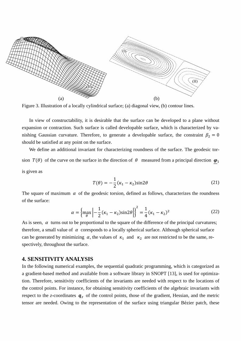
(a) (b) Figure 3. Illustration of a locally cylindrical surface; (a) diagonal view, (b) contour lines.
In view of constructability, it is desirable that the surface can be developed to a plane without expansion or contraction. Such surface is called developable surface, which is characterized by va-nishing Gaussian curvature. Therefore, to generate a developable surface, the constraint 0 should be satisfied at any point on the surface.
We define an additional invariant for characterizing roundness of the surface. The geodesic tor-
sion of the curve on the surface in the direction of measured from a principal direction
is given as
12 sin2 (21)
The square of maximum of the geodesic torsion, defined as follows, characterizes the roundness of the surface:
max12 sin2
14 (22)
As is seen, turns out to be proportional to the square of the difference of the principal curvatures; therefore, a small value of coresponds to a locally spherical surface. Although spherical surface can be generated by minimizing , the values of and are not restricted to be the same, re-spectively, throughout the surface. 4. SENSITIVITY ANALYSIS In the following numerical examples, the sequential quadratic programming, which is categorized as a gradient-based method and available from a software library in SNOPT [13], is used for optimiza-tion. Therefore, sensitivity coefficients of the invariants are needed with respect to the locations of the control points. For instance, for obtaining sensitivity coefficients of the algebraic invariants with respect to the z-coordinates of the control points, those of the gradient, Hessian, and the metric tensor are needed. Owing to the representation of the surface using triangular Bezier patch, these

sensitivity coefficients can be derived explicitly as follows:
,
,
,
, ,
, , (23)
,
, ,
, ,
, , , ,
, , , , (24)
,
2, , ,
, ,2
,
(25)
The basis functions are explicitly differentiated with respect to and , and the sensitivity coeffi-cients of the algebraic invariants can be obtained simply by differentiating their definitions. This way, optimization can be carried out with small computational cost. 5. BÉZIER SURFACE WITH TRIANGULAR PLAN Consider first a shell surface with triangular plan (Model 1) that consists of a Bézier surface with triangular plan as shown in Figure 4. The shell is pin-supported at the three corners; however, there exist two supports at each corner, as shown in blank circles in Figure 4, to prevent stress concentra-tion. The span length is 30 m and the radius of curvature is 17.06 m, which result in the rise of 4.84 m. The middle surface of shell is modeled using the triangular Bézier patch of order 4. The z-coordinates of all the 15 control points, as shown in filled circles, are chosen as variables, while the locations of the supports are fixed by assigning the constraints. The shell is discretized to triangular finite elements for static analysis. The constant-strain element [14] is used for in-plane deformation, and the non-conforming triangular element by Zienkiewicz et al. [15] is used for out-of-plane de-formation. Each node has six degrees of freedom, and the two elements are coupled with respect to the translational displacements. The number of elements for static analysis is 253. The shell has the uniform thickness of 0.1 m and is subjected to self-weight, which is supposed to be sufficiently small so that the deformation is small and the shell remains in the elastic range. The material of is sup-posed to be concrete with Young’s modulus 21.0 kN/mm2, Poisson’s ratio 0.17, and weight density 24.0 kN/m3.

(a)
(b) Figure 4. Shell surface with triangular plan (Model 1); (a) plan and diagonal view, (b) Bézier patch
and control points.
In each of the optimization problem formulated below, the total number of degrees of freedom, nodal displacement vector, linear stiffness matrix, total middle-surface area, and vector consisting of z-coordinates of the supports are denoted by , , , , and , respectively. The value of initial shape is denoted by the subscript 0. The design variables are the z-coordinates
of the control points, because various shapes can be successfully represented by varying z-coordinates only. Optimization is carried out on a PC with Core 2 duo with 2GB RAM. Minimization of strain energy without constraints on algebraic invariants We first find the optimal shape without constraint on an algebraic invariant. The strain energy is mi-nimized as follows under upper-bound constraint on the area:
minimize
12
T
subject to 00
(26)
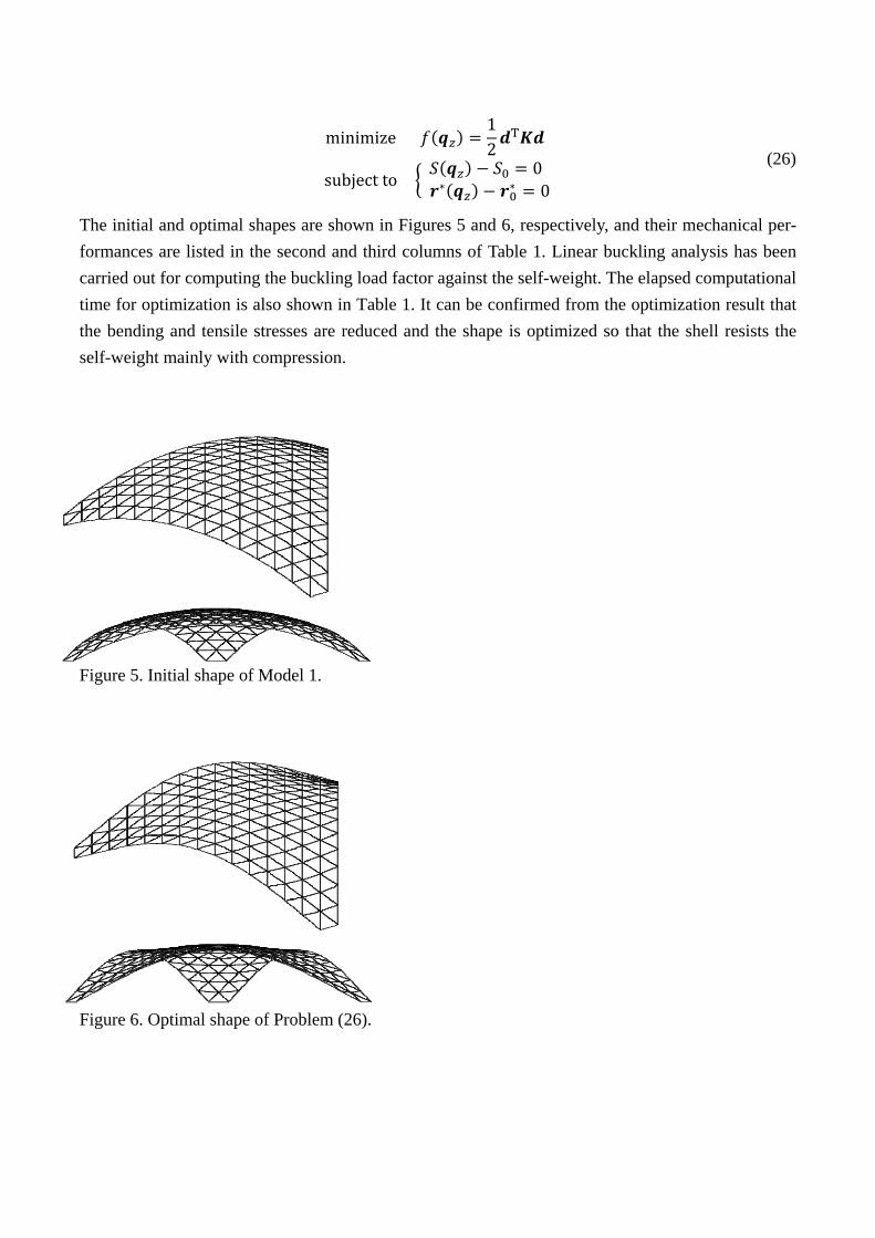
The initial and optimal shapes are shown in Figures 5 and 6, respectively, and their mechanical per-formances are listed in the second and third columns of Table 1. Linear buckling analysis has been carried out for computing the buckling load factor against the self-weight. The elapsed computational time for optimization is also shown in Table 1. It can be confirmed from the optimization result that the bending and tensile stresses are reduced and the shape is optimized so that the shell resists the self-weight mainly with compression. Figure 5. Initial shape of Model 1. Figure 6. Optimal shape of Problem (26).
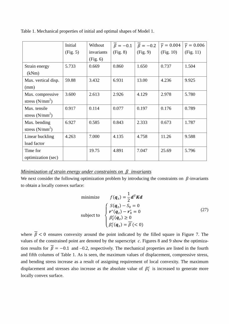
Table 1. Mechanical properties of initial and optimal shapes of Model 1.
Initial (Fig. 5)
Without invariants (Fig. 6)
0.1(Fig. 8)
0.2(Fig. 9)
0.004 (Fig. 10)
0.006(Fig. 11)
Strain energy (kNm)
5.733 0.669 0.860 1.650 0.737 1.504
Max. vertical disp. (mm)
59.88 3.432 6.931 13.00 4.236 9.925
Max. compressive stress (N/mm2)
3.600 2.613 2.926 4.129 2.978 5.780
Max. tensile stress (N/mm2)
0.917 0.114 0.077 0.197 0.176 0.789
Max. bending stress (N/mm2)
6.927 0.585 0.843 2.333 0.673 1.787
Linear buckling load factor
4.263 7.000 4.135 4.758 11.26 9.588
Time for optimization (sec)
19.75 4.891 7.047 25.69 5.796
Minimization of strain energy under constraints on invariants We next consider the following optimization problem by introducing the constraints on -invariants to obtain a locally convex surface:
minimize12
T
subject to
00
0 0
(27)
where 0 ensures convexity around the point indicated by the filled square in Figure 7. The values of the constrained point are denoted by the superscript . Figures 8 and 9 show the optimiza-tion results for 0.1 and −0.2, respectively. The mechanical properties are listed in the fourth and fifth columns of Table 1. As is seen, the maximum values of displacement, compressive stress, and bending stress increase as a result of assigning requirement of local convexity. The maximum displacement and stresses also increase as the absolute value of is increased to generate more locally convex surface.
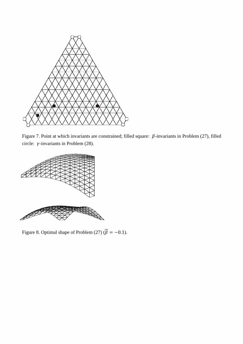
Figure 7. Point at which invariants are constrained; filled square: -invariants in Problem (27), filled circle: -invariants in Problem (28). Figure 8. Optimal shape of Problem (27) ( 0.1).
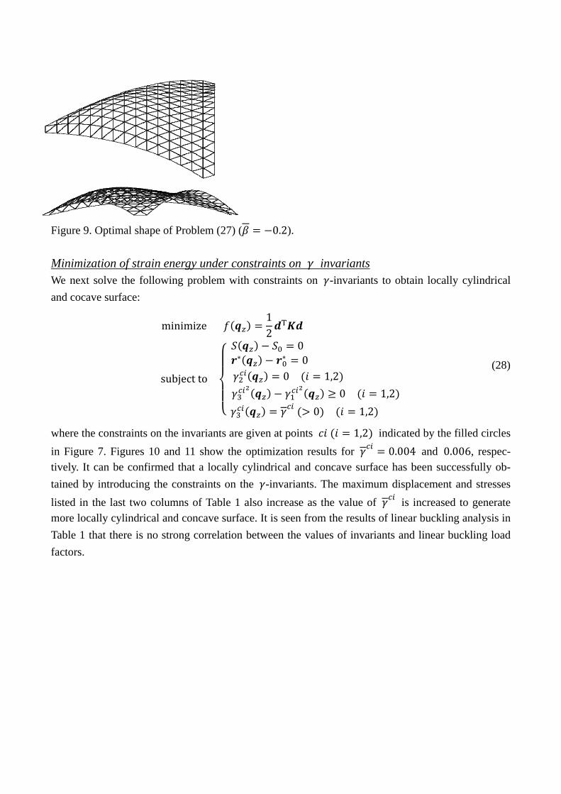
Figure 9. Optimal shape of Problem (27) ( 0.2). Minimization of strain energy under constraints on invariants We next solve the following problem with constraints on -invariants to obtain locally cylindrical and cocave surface:
minimize12
T
subject to
0 0
0 1,2 0 1,2
0 1,2
(28)
where the constraints on the invariants are given at points 1,2 indicated by the filled circles in Figure 7. Figures 10 and 11 show the optimization results for 0.004 and 0.006, respec-tively. It can be confirmed that a locally cylindrical and concave surface has been successfully ob-tained by introducing the constraints on the -invariants. The maximum displacement and stresses listed in the last two columns of Table 1 also increase as the value of is increased to generate more locally cylindrical and concave surface. It is seen from the results of linear buckling analysis in Table 1 that there is no strong correlation between the values of invariants and linear buckling load factors.
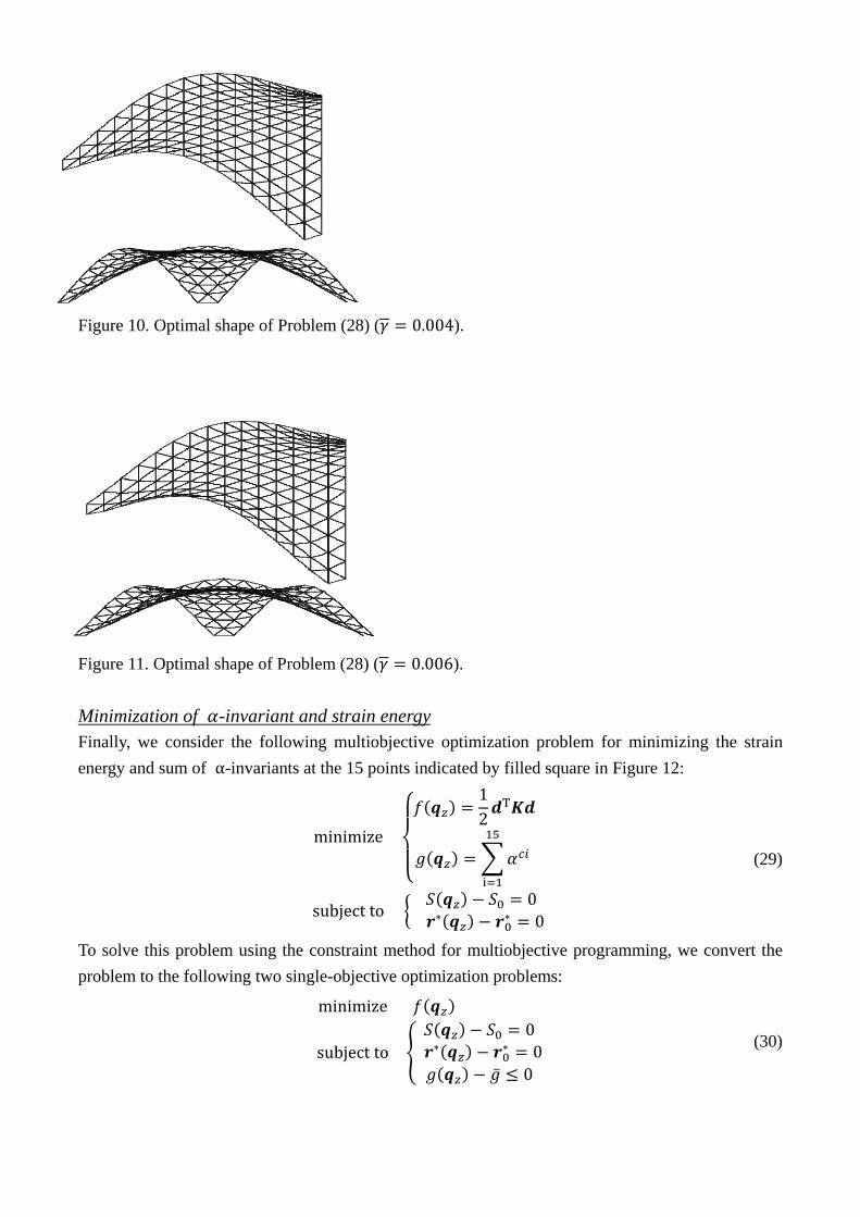
Figure 10. Optimal shape of Problem (28) ( 0.004). Figure 11. Optimal shape of Problem (28) ( 0.006). Minimization of -invariant and strain energy Finally, we consider the following multiobjective optimization problem for minimizing the strain energy and sum of α-invariants at the 15 points indicated by filled square in Figure 12:
minimize
12
T
subject to 00
(29)
To solve this problem using the constraint method for multiobjective programming, we convert the problem to the following two single-objective optimization problems:
minimize
subject to00
0
(30)
minimize
subject to00
0
(31)
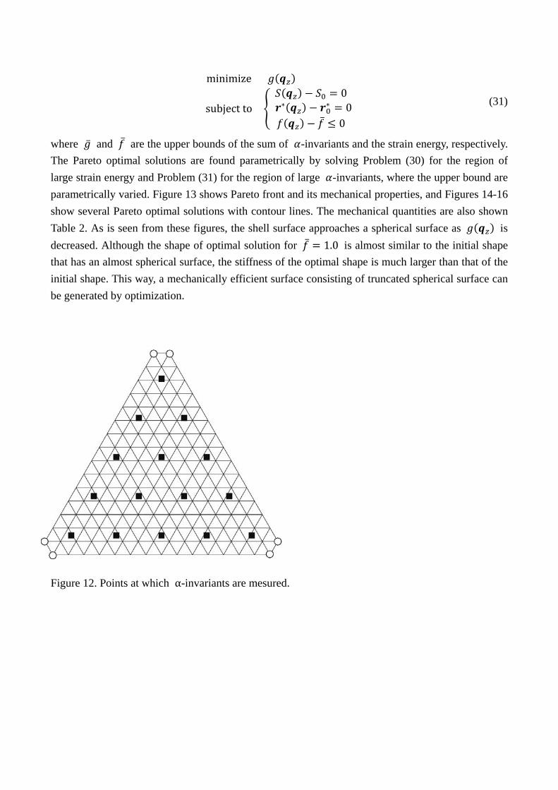
where and are the upper bounds of the sum of -invariants and the strain energy, respectively. The Pareto optimal solutions are found parametrically by solving Problem (30) for the region of large strain energy and Problem (31) for the region of large -invariants, where the upper bound are parametrically varied. Figure 13 shows Pareto front and its mechanical properties, and Figures 14-16 show several Pareto optimal solutions with contour lines. The mechanical quantities are also shown Table 2. As is seen from these figures, the shell surface approaches a spherical surface as is decreased. Although the shape of optimal solution for 1.0 is almost similar to the initial shape that has an almost spherical surface, the stiffness of the optimal shape is much larger than that of the initial shape. This way, a mechanically efficient surface consisting of truncated spherical surface can be generated by optimization.
Figure 12. Points at which α-invariants are mesured.
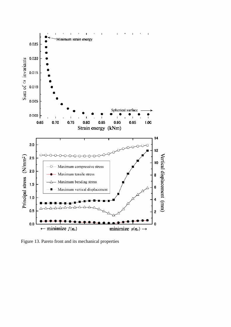
Figure 13. Pareto front and its mechanical properties
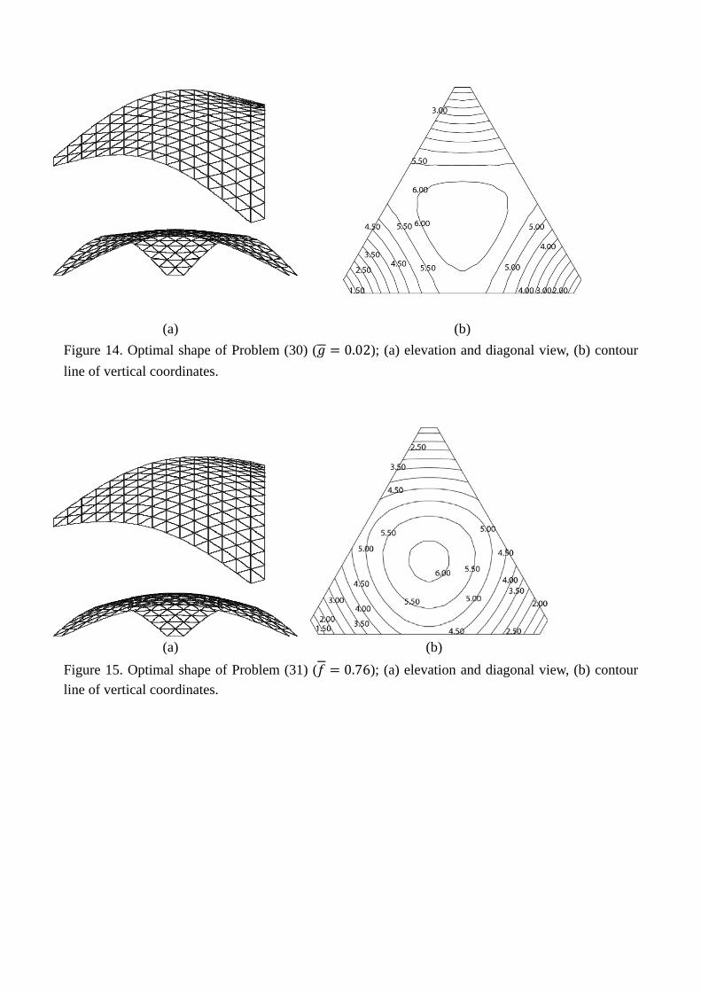
(a) (b) Figure 14. Optimal shape of Problem (30) ( 0.02); (a) elevation and diagonal view, (b) contour line of vertical coordinates.
(a) (b) Figure 15. Optimal shape of Problem (31) ( 0.76); (a) elevation and diagonal view, (b) contour line of vertical coordinates.

(a) (b) Figure 16. Optimal shape of Problem (31) ( 1.00); (a) elevation and diagonal view, (b) contour line of vertical coordinates. Table 2. Mechanical properties of several Pareto optimal solutions considering -invariants and strain energy.
0.02(Fig. 14)
0.76(Fig. 15)
1.00(Fig. 16)
Initial (Fig. 5)
Strain energy (kNm)
0.672 0.760 1.000 5.733
Sum of invariants
0.020 1.6×10⁻³ 4.5×10⁻⁴ 2.9×10⁻⁶
Max. vertical disp. (mm)
3.419 3.783 11.99 59.88
Max. compressive stress (N/mm2)
2.593 2.661 2.986 3.600
Max. tensile stress (N/mm2)
0.118 0.041 0.145 0.917
Max. bending stress (N/mm2)
0.611 0.404 1.367 6.927
Linear buckling load factor
5.517 2.938 3.966 4.263
Time for optimization (sec)
34.14 9.922 3.171

6. BÉZIER SURFACE WITH IRREGULAR PLAN So far, we considered a surface with regular triangular plan. In this section, optimal shapes are found for the shell surface with irregular plan (Model 2) as shown in Figure 17, in order to demonstrate the effectiveness of using the triangular Bézier patch. The geometry of the control net is also shown in Figure 17. The shell has the uniform thickness of 0.2 m, the rise is 8.0 m, and other parameters are the same as those of Model 1 in Sec. 5. The surface is modeled using six triangular Bézier patches of order 4, and the design variables are the z-coordinates of 28 control points as shown in the filled circle in Figure 17, where the symmetry conditions are utilized and the locations of supports are fixed. The continuity of gradient and curvature along the interior boundary between Bézier patches is not necessarily satisfied.
(a)
(b) Figure 17. Shell surface with irregular plan (Model 2); (a) Plan and diagonal view, (b) Bézier patches and control points.
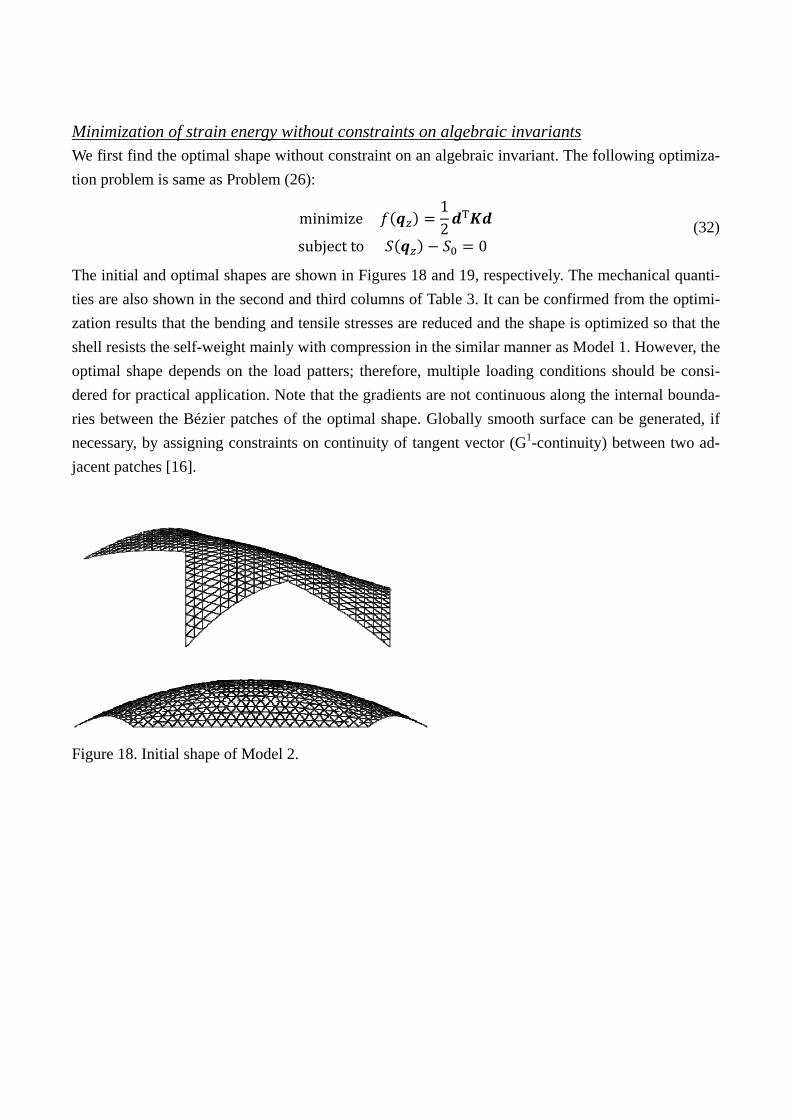
Minimization of strain energy without constraints on algebraic invariants We first find the optimal shape without constraint on an algebraic invariant. The following optimiza-tion problem is same as Problem (26):
minimize12
T
subject to 0 (32)
The initial and optimal shapes are shown in Figures 18 and 19, respectively. The mechanical quanti-ties are also shown in the second and third columns of Table 3. It can be confirmed from the optimi-zation results that the bending and tensile stresses are reduced and the shape is optimized so that the shell resists the self-weight mainly with compression in the similar manner as Model 1. However, the optimal shape depends on the load patters; therefore, multiple loading conditions should be consi-dered for practical application. Note that the gradients are not continuous along the internal bounda-ries between the Bézier patches of the optimal shape. Globally smooth surface can be generated, if necessary, by assigning constraints on continuity of tangent vector (G1-continuity) between two ad-jacent patches [16]. Figure 18. Initial shape of Model 2.
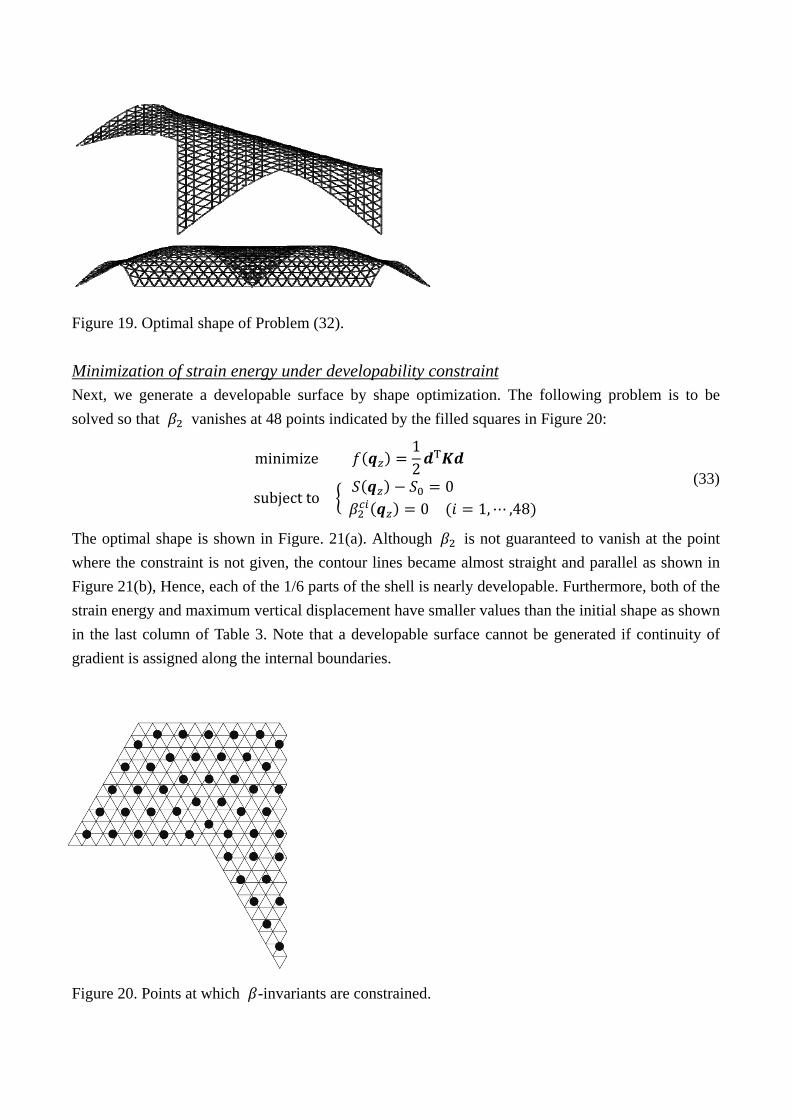
Figure 19. Optimal shape of Problem (32). Minimization of strain energy under developability constraint Next, we generate a developable surface by shape optimization. The following problem is to be solved so that vanishes at 48 points indicated by the filled squares in Figure 20:
minimize
12
T
subject to0
0 1, ,48
(33)
The optimal shape is shown in Figure. 21(a). Although is not guaranteed to vanish at the point where the constraint is not given, the contour lines became almost straight and parallel as shown in Figure 21(b), Hence, each of the 1/6 parts of the shell is nearly developable. Furthermore, both of the strain energy and maximum vertical displacement have smaller values than the initial shape as shown in the last column of Table 3. Note that a developable surface cannot be generated if continuity of gradient is assigned along the internal boundaries. Figure 20. Points at which -invariants are constrained.

(a) (b) Figure 21. Optimal shape of Problem (33); (a) elevation and diagonal view, (b) Contour line of ver-tical coordinates. Table 3. Mechanical properties of initial and optimal solutions.
Initial (Fig. 18)
Without invariants (Fig. 19)
With deve-lopable condition (Fig. 21)
Strain energy (kNm)
19.89 5.440 6.287
Max. vertical disp. (mm)
43.77 3.989 8.571
Max. compressive stress (N/mm2)
14.32 14.09 14.88
Max. tensile stress (N/mm2)
2.394 0.423 0.435
Max. bending stress (N/mm2)
13.38 0.364 1.310
Linear buckling load factor
4.806 4.742 3.502
Time for optimization (sec)
156.2 2427

7. CONCLUSIONS The local geometrical properties of the shell surface can be explicitly controlled by solving an opti-mization problem with constraints on the algebraic invariants of the surface. Moreover, a developa-ble surface can be obtained by assigning the constraint such that the Gaussian curvature vanishes at the sufficiently many specified points on the surface. A locally spherical surface can also be obtained by minimizing the sum of the difference of principal curvatures at the specified points.
Using the proposed approach, the shell surface can be locally controlled to satisfy requirements on architectural planning as well as the architect’s preference without too much sacrificing the me-chanical properties. The local geometrical properties can be quantitatively defined based on the al-gebraic invariants. For the concrete shells, ruled surfaces such as HP surface are often used to im-prove constractability. However, it is more preferable to define the surface as a developed surface, because scaffolding for forming concrete surface can be easily made without extension or contrac-tion from a plate. Although construction of complex surface is possible owing to new technologies of computer-aided manufacturing, it is still beneficial to design a shell as an assemblage of developable surfaces if mechanical properties are not strongly deteriorated. It has been shown that a surface with irregular plan, which is very difficult to represent using a tensor product Bézier surface, can be mod-eled as an assemblage of triangular Bézier patches. Only strain energy has been incorporated as a mechanical property in the objective function, because the main purpose of this paper is to show effectiveness of using algebraic invariants for representing geometrical properties of shells with irregular plan modeled using triangular Bézier patches. It is also important to note that bending deformation is avoided and a shell resisting external load through compressive stresses is successfully generated by minimizing the strain energy. The loading condi-tion is also restricted to self-weight only. Linear buckling analysis has been carried out for the op-timal shapes, and no strong correlation has been found between the strain energy (stiffness) and strength (buckling load). Other mechanical properties such as maximum equivalent stresses and dis-placements under several loading conditions may be incorporated in the future study. The reinforce-ments by steel bars, material nonlinearity, and optimal shape with variable thickness may also be considered.
It may be concluded that the algebraic invariants are effective indices representing the local geometrical properties of the surface, and the optimal shell shape considering the geometrical cha-racteristics, constructability, and mechanical rationality can be generated using the proposed ap-proach at the early design stage. APPENDIX Basic terminologies of tensor algebra are given below for the completeness of the paper.
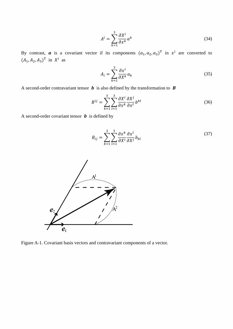
Let denote an arbitrary vector defined in a coordinate system 1,2,3 . The vector is also defined in a different coordinate system 1,2,3 . The vector is called a contravariant vector if its components , , T in are converted to , , T in as
(34)
By contrast, is a covariant vector if its components , , T in are converted to , , T in as
(35)
A second-order contravariant tensor is also defined by the transformation to
(36)
A second-order covariant tensor is defined by
(37)
Figure A-1. Covariant basis vectors and contravariant components of a vector.

Figure A-2. Contravariant basis vector and covariant components of a vector.
For example, consider a two-dimensional covariant basis vectors and contravariant basis
vectors as shown in Figures A-1 and A-2, respectively. The components of the location vector with respect to are contravariant components denoted as , whereas the components with re-spect to are contravariant components . Since the vector is independent of the coordinate sys-tem, the following equalities hold:
(38)
which means that the summation of the products of covariant and contravariant components are in-variant on the coordinate system. The algebraic invariants are defined based on this property. The metric tensors are defined using the inner products of the basis vectors as · · (39) which are used for transformation of vectors and tensors as well as the definition of length of a vector as shown in Figure A-3 as
· · (40)
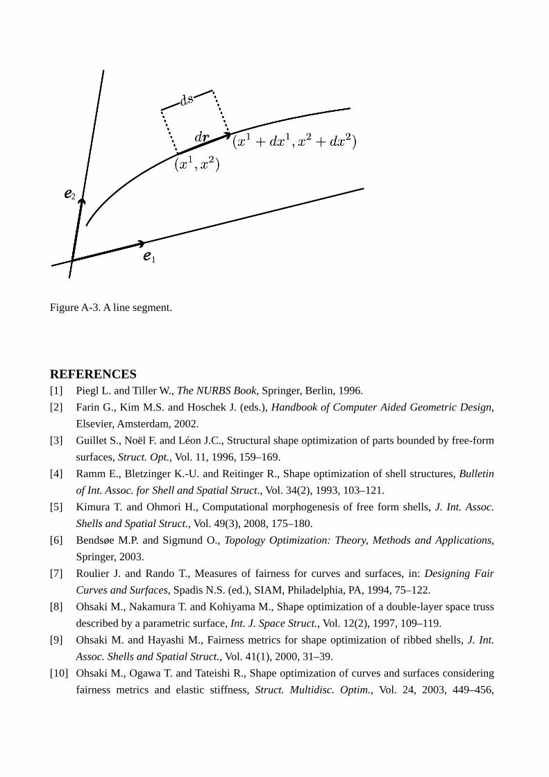
Figure A-3. A line segment. REFERENCES [1] Piegl L. and Tiller W., The NURBS Book, Springer, Berlin, 1996. [2] Farin G., Kim M.S. and Hoschek J. (eds.), Handbook of Computer Aided Geometric Design,
Elsevier, Amsterdam, 2002. [3] Guillet S., Noël F. and Léon J.C., Structural shape optimization of parts bounded by free-form
surfaces, Struct. Opt., Vol. 11, 1996, 159–169. [4] Ramm E., Bletzinger K.-U. and Reitinger R., Shape optimization of shell structures, Bulletin
of Int. Assoc. for Shell and Spatial Struct., Vol. 34(2), 1993, 103–121. [5] Kimura T. and Ohmori H., Computational morphogenesis of free form shells, J. Int. Assoc.
Shells and Spatial Struct., Vol. 49(3), 2008, 175–180. [6] Bendsøe M.P. and Sigmund O., Topology Optimization: Theory, Methods and Applications,
Springer, 2003. [7] Roulier J. and Rando T., Measures of fairness for curves and surfaces, in: Designing Fair
Curves and Surfaces, Spadis N.S. (ed.), SIAM, Philadelphia, PA, 1994, 75–122. [8] Ohsaki M., Nakamura T. and Kohiyama M., Shape optimization of a double-layer space truss
described by a parametric surface, Int. J. Space Struct., Vol. 12(2), 1997, 109–119. [9] Ohsaki M. and Hayashi M., Fairness metrics for shape optimization of ribbed shells, J. Int.
Assoc. Shells and Spatial Struct., Vol. 41(1), 2000, 31–39. [10] Ohsaki M., Ogawa T. and Tateishi R., Shape optimization of curves and surfaces considering
fairness metrics and elastic stiffness, Struct. Multidisc. Optim., Vol. 24, 2003, 449–456,

Erratum: Vol. 27, 2004, 250–258. [11] Fujita S. and Ohsaki M., Shape optimization of shells considering strain energy and algebraic
invariants of parametric surface, J. Struct. Constr. Eng., AIJ, Vol. 74, No. 639, 2009, 841–847. (in Japanese)
[12] Iri M., Shimakawa Y., and Nagai T., Extraction of invariants from digital elevation data with application to terrain topography, Nonlinear Analysis, Vol.47, 2001, 5585–5598.
[13] Gill P., Murray W., and Saunders M., User’s Guide for SNOPT Version 7: Software for Large-Scale Nonlinear Programming, Stanford Business Software Inc., 2008.
[14] Zienkiewicz O.C., The Finite Element Method in Engineering Science, McGraw-Hill, 1971. [15] G. P. Bazeley, Y. K. Cheung, B. M. Irons and O. C. Zienkiewicz, Triangular Elements in Plate
Bending – Conforming and Nonconforming Solutions, Proceedings First Conference on Ma-trix Methods in Structural Mechanics, 547–576, 1966.
[16] Wen-Hui Du and Francis J M Schmitt, On the G1 continuity of piecewise Bézier surfaces: A review with new results,Computer-Aided Design, Vol. 22(9), pp.556-573, 1990.