shallow geothermal energy · shallow geothermal energy by dr. burkhard sanner the underground in...
TRANSCRIPT
SHALLOW GEOTHERMAL ENERGY
by Dr. Burkhard Sanner
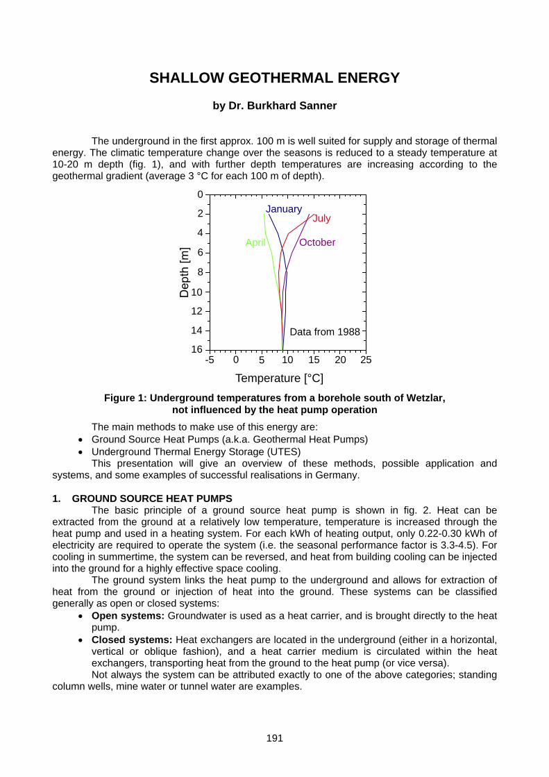
The underground in the first approx. 100 m is well suited for supply and storage of thermal energy. The climatic temperature change over the seasons is reduced to a steady temperature at 10-20 m depth (fig. 1), and with further depth temperatures are increasing according to the geothermal gradient (average 3 °C for each 100 m of depth).
Temperature [°C]0-5 5 10 15 20 25
0
2
4
6
8
10
12
14
16
January
April
July
October
Data from 1988
Figure 1: Underground temperatures from a borehole south of Wetzlar,
not influenced by the heat pump operation The main methods to make use of this energy are:
• Ground Source Heat Pumps (a.k.a. Geothermal Heat Pumps) • Underground Thermal Energy Storage (UTES)
This presentation will give an overview of these methods, possible application and systems, and some examples of successful realisations in Germany.
1. GROUND SOURCE HEAT PUMPS
The basic principle of a ground source heat pump is shown in fig. 2. Heat can be extracted from the ground at a relatively low temperature, temperature is increased through the heat pump and used in a heating system. For each kWh of heating output, only 0.22-0.30 kWh of electricity are required to operate the system (i.e. the seasonal performance factor is 3.3-4.5). For cooling in summertime, the system can be reversed, and heat from building cooling can be injected into the ground for a highly effective space cooling.
The ground system links the heat pump to the underground and allows for extraction of heat from the ground or injection of heat into the ground. These systems can be classified generally as open or closed systems:
• Open systems: Groundwater is used as a heat carrier, and is brought directly to the heat pump.
• Closed systems: Heat exchangers are located in the underground (either in a horizontal, vertical or oblique fashion), and a heat carrier medium is circulated within the heat exchangers, transporting heat from the ground to the heat pump (or vice versa). Not always the system can be attributed exactly to one of the above categories; standing
column wells, mine water or tunnel water are examples.
191

Heating system
Heat Pump
Figure 2: Schematic of a ground source heat pump
To choose the right system for a specific installation, several factors have to be considered: Geology and hydrogeology of the underground (sufficient permeability is a must for open systems), area and utilisation on the surface (horizontal closed systems require a certain area), existence of potential heat sources like mines, and the heating and cooling characteristics of the building(s). In the design phase, more accurate data for the key parameters for the chosen technology are necessary, to size the ground system in such a way that optimum performance is achieved with minimum cost.
1.1 Open systems
Main technical part of open systems are groundwater wells, to extract or inject water from/to water bearing layers in the underground („aquifers“). In most cases, two wells are required („doublette“, fig. 3), one to extract the groundwater, and one to re-inject it into the same aquifer it was produced from.
Pump
water table
Figure 3: Groundwater heat pump (doublette)
With open systems, a powerful heat source can be exploited at comparably low cost. On the other hand, groundwater wells require some maintenance, and open systems in general are confined to sites with suitable aquifers. The main requirements are:
• Sufficient permeability, to allow production of the desired amount of groundwater with little drawdown.
• Good groundwater chemistry, e.g. low iron content, to avoid problems with scaling, clogging and corrosion.
192

Open systems tend to be used for larger installations. The most powerful ground source heat pump system world-wide uses groundwater wells to supply ca. 10 MW of heat and cold to a hotel and offices in Louisville, Kentucky, USA.
1.2 Closed systems a) horizontal
The closed system easiest to install is the horizontal ground heat exchanger (synonym: ground heat collector, horizontal loop). Due to restrictions in the area available, in Western and Central Europe the individual pipes are laid in a relatively dense pattern, connected either in series or in parallel (fig. 4).
Connection in series
Connection in parallel Figure 4: Horizontal ground heat exchanger (European style)
To save surface area with ground heat collectors, some special ground heat exchangers have been developed. Exploiting a smaller area at the same volume, these collectors are best suited for heat pump systems for heating and cooling, where natural temperature recharge of the ground is not vital. Spiral forms (fig. 5) are popular in USA, mainly in the form of the so-called „slinky“ collectors (placed horizontally in a wide trench like in the figure, or vertically in a narrow trench).
"Slinky" collector Svec spiral collector Figure 5: Spiral-type ground heat exchangers (North America)
The main thermal recharge for all horizontal systems is provided for mainly by the solar radiation to the earth´s surface. It is important not to cover the surface above the ground heat collector. b) vertical
Because the temperature below a certain depth (ca. 15-20 m) remains constant over the year, and because of the need to install sufficient heat exchange capacity under a confined surface area, vertical ground heat exchangers (borehole heat exchangers) are widely favoured. In a standard borehole heat exchanger, plastic pipes (polyethylene or polypropylene) are installed in boreholes, and the remaining room in the hole is filled (grouted) with a pumpable material.
193

Manifold inside or at the building
Figure 6: Borehole heat exchangers (double-U-pipe)
Several types of borehole heat exchangers have been used or tested; the two possible basic concepts are (fig. 7):
• U-pipes, consisting of a pair of straight pipes, connected by a 180°-turn at the bottom. One, two or even three of such U-pipes are installed in one hole. The advantage of the U-pipe is low cost of the pipe material, resulting in double-U-pipes being the most frequently used borehole heat exchangers in Europe.
• Coaxial (concentric) pipes, either in a very simple way with two straight pipes of different diameter, or in complex configurations. The borehole filling and the heat exchanger walls account for a drop in temperature, which
can be summarised as borehole thermal resistance. Thermally enhanced grouting (filling) materials have been developed to reduce this losses.
Single-U-pipe Double-U-pipe25-32 mm
Simple coaxial Complex coaxial
Figure 7: Cross-sections of different types of borehole heat exchangers
Ground source heat pump plants of every size have been realised with borehole heat exchangers, ranging from small houses with just one borehole to large buildings, requiring whole fields of borehole heat exchangers. The highest number of boreholes for a single plant in Europe may be the head office of the German Air Traffic Control (Deutsche Flugsicherung), with 154 borehole heat exchangers each 70 m deep. The largest single plant in the world heats and cools the Richard Stockton College in New Jersey and comprises 400 boreholes each 130 m deep.
Another trend are residential areas with heat supply from ground source heat pumps; an example with ca. 130 houses with individual ground source heat pumps and one or two borehole heat exchangers for each house can be found in Werne, Germany, on an area of ca. 50’000 m2 (fig. 9).
A perfect example for the total integration of ground source heat pump systems is the use for filling stations. The first plant was installed for the chain Philipps 66 in Prarie Village, Kansas.
194

The heat pump used for space heating and cooling is coupled to ten borehole heat exchangers each 99 m deep. The convenience store appliances (14 kW walk-in cooler, freezer and icemaker) have their own separate water-cooled compressors, and waste heat from the appliances is discharged into the same ground loops used by the space conditioning system (fig. 10). This installation has reduced electricity consumption by 40 % compared to air-cooled equipment of the same size. For the wintertime car wash operations, the ground source heat pump is coupled to radiant floor heating in the car wash bays and below the concrete at the car wash entrances and exits.
Figure 8: Architect´s concept of the residential area „Am Fürstenhof“ in Werne
(Behr+Partner, Schwerte)
HP
walk-in cooler
freezer
icemaker
snow- and ice melting
space heating and cooling
Figure 9: Schematic of ground source system for filling station in USA
Further Philipps 66 stations use ground source heat pumps in Colorado, Oklahoma and Texas, and another example is Conoco's "Skunk Creek" Service Station in Sandstone, Minnesota. Similar systems have been tested for fast food chains (e.g. McDonalds).
The design of borehole heat exchangers for small, individual applications can be done with tables, empirical values and guidelines (existing in Germany and Switzerland). The most important guideline currently in use is issued by the German Association of Engineers (Verein
195

Deutscher Ingenieure, VDI) with the title „VDI 4640: Thermal Use of the Underground“. This guideline consists of 4 parts (the first three published by the date of the EGS), dealing with:
• fundamentals, environmental aspects, licensing • ground source heat pumps • underground thermal energy storage • other uses, direct uses
A popular parameter to calculate the required length of borehole heat exchangers is the specific heat extraction, expressed in Watt per meter borehole length (fig. 11). Typical values range between 40-70 W/m, dependent upon geology (thermal conductivity), annual hours of heat pump operation, number of neighbouring boreholes, etc.
Single family house, 10 kW heating demand
0
10
20
30
40
50
60
70
1 1.5 2 2.5 3 3.5 4ground thermal conductivity [W/m/K]
values after VDI 4640
2 borehole heat exchangers
with groundwater flow
without groundwater flow
Figure 10: Example of specific heat extraction values for a small ground source heat pump,
no domestic hot water (heat pump operation time 1800 h/a) For larger borehole heat exchanger plants, calculations have to be made to determine
the required number and length of borehole heat exchangers. Programs for use on PC exist in USA and Europe, and for difficult cases, simulation with numerical models can be done. The design tool mostly used in Europe is the „Earth Energy Designer“ (EED), developed by the universities of Lund, Sweden, and Giessen, Germany. A demo version of the programme and further information can be found on the website of Lund University under:
http://www.buildingphysics.com (goto „Software“)
0,0 m
21,1 m
0,0 m 30,4 m Figure 11: Isotherms around 3 borehole heat exchangers, calculated with TRADIKON-3D
Numerical simulation can help to solve even the most difficult design problems, in particular if the influence of groundwater flow has to be considered. An example of the temperature development around three borehole heat exchangers is shown in fig. 11, modeled with the code TRADIKON-3D developed in Giessen.
196

To get reliable input parameters for such calculations, the Thermal Response Test has been developed (fig. 12). This test allows determination of thermal parameters of the underground on site.
Figure 12: Schematic of Thermal Response Test and the equipment on site A special case of vertical closed systems are „energy piles“, i.e. foundation piles equipped
with heat exchanger pipes (fig. 13). All kind of piles can be used (pre-fabricated or cast on site), and diameters may vary from 40 cm to over 1 m.
1.3 Other systems
There is a number of ground systems neither to be categorized as open or closed.
197

Foundation piles("Energy piles")
ca. 700 mmca. 900 mm
Wall of pile
steel cage
Heatexchangerpipes
(reinforcement)
Figure 13: Energy piles and cross-section of a pile with 3 loops
In a standing column well, water is pumped from the bottom of the well and, after leaving the heat pump, percolated through gravel in the annulus of the well. Standing column wells need a certain depth to provide enough power without freezing of the water, and thus most plants have boreholes several hundred meter deep. Examples are known from Europe (Switzerland and Germany) and from USA. With the expensive borehole, the technology is not suited to small installations.
A very promising concept is the use of water from mines and tunnels. This water has a steady temperature the whole year over and is easily accessible. Examples with mine water use exist in Germany (Saxonia, fig. 14) and Canada. Tunnel water is used in the village of Oberwald at the Western entrance of the Furka rail tunnel in Switzerland and in Airolo, where water from the Gotthard road tunnel provide the heat source for a heat pump in the road maintenance facility. With the huge tunnel constructions ongoing in the Alps, new potential for this type of heat source is developing.
School
Figure 14: Heat pump using mine water (example of Ehrenfriedersdorf,
Germany, with abandoned tin mine)
198

2. UNDERGROUND THERMAL ENERGY STORAGE (UTES) In UTES, heat, cold or both are stored in the underground. The methods of ground
coupling (fig. 15) are essentially the same as for ground source heat pumps, with open systems (ATES) and closed systems (BTES).
Borehole Storage (BTES)Aquifer Storage (ATES)
- high specific heat- medium thermal conductivity- no groundwater flow
Examples:- Sediments like shale, marl, clay etc.; limestone, sandstone and others
- Igneous rocks like granite, gabbro, etc.;
- medium to high hydraulic conductivity and transmissivity- high porosity- low or none groundwater flow Examples:- Porous aquifers in sand, gravel eskers- Fractured aquifers in limestone, sand- stone, igneous or metamorphic rock
may also be suitable
some metamorphic rocks like gneiss
Systems with boreholes and pipesGroundwater as heat carrier
Figure 15: Types of Underground Thermal Energy Storage and geological preferences
Cold storage is starting to become very popular, because cost for space cooling normally are rather high. They use cold air in winter to cool down the underground store and use this cold again in summer. In the 60s, China was a major pioneer in this field, with a number of plants in the Shanghai area. Today, the main activity on seasonal cold storage is in Belgium, the Netherlands, and Southern Sweden.
A combination of heat and cold storage is the connection of road surfaces to an UTES (fig. 17). Heat from solar radiation on the surface can be stored and used in winter for de-icing and snow melting on that surface. The system is used mainly on bridges, but can also be applied to any other road surface, airport runway, etc.
Thermischer Untergrundspeicher (Erdwärmesonden)
Pumpen-haus
Fahrbahn-heizung
Figure 17: UTES for de-icing of road surfaces
199

Heat Storage can make use of solar or waste heat in summertime to use it for heating in winter. Major plants in Germany are at Neckarsulm, were a BTES system is charged with heat from solar collectors and heats a housing district , or in Berlin, were waste heat from heat-and-power-co-generation in summer is stored in an ATES for heating in winter (fig. 18). The Berlin plant supplies heat and cold to the German Parliament buildings (Reichstag building and surrounding offices), and for the first time incorporates two ATES systems at different levels, the upper for cold storage, and the lower for heat storage (up to 70 °C). System parameters are:
The total energy demand is as follows: • power: 8'600 kW 19'500 MWh/a • heat: 12'500 kW 16'000 MWh/a • cold: 6'200 kW 2'800 MWh/a
To meet the heat and cold demand, several units are installed within the Reichstag building and the surrounding buildings:
• 2 heat- and power co-generation plants • 3 absorption heat pumps (heating/cooling) • 1 boiler (for peak heating) • 2 compressor chillers (for peak cooling)
All excess heat from power generation is stored in the lower ATES system, and a big part of the cooling is provided from the upper ATES.
Cold storage
Heat storage
Biofuel
Heat a. power co-generation
Heat El. power
ca. 60 m below ground
>300 m below ground
Rupel clay (aquitard)
Figure 18: Schematic of Berlin Reichstagsgebäude ATES (not to scale)
3. CONCLUSION
Shallow geothermal energy applications can be used in a variety of sectors, from house heating to process cooling and road de-icing. Design and construction is well understood and done routinely, however, skill and knowledge is required to guarantee successful installations. Ground Source Heat Pumps in some of the countries have a wide application in simple cases of heating a residential house (Table 1). In future, further good opportunities for use of this technology can be seen within Europe mainly in the commercial sector (offices, factories, department stores, etc.), where heating and cooling is required.
200

Table 1: Estimation of GSHP-numbers in Europe by the end of 1998, using published information (with year) and extrapolation according to published rates of increase
Number of GSHP-plants Remarks Austria (1996) ca. 13000 annual increase ca. 1600 Germany (1995) 14 000-22 000 240-450 MW thermal capacity,
annual increase ca. 2000 Netherlands (1997) ca. 900 market development is about to begin Sweden (1998) more than 60 000 ca. 330 MW thermal capacity Switzerland (1998) more than 20 000 ca. 300 MW thermal capacity,
annual increase ca. 10 % France (1999) 10 000 - 20 000 mainly horizontal GSHP heating capacity
< 15 kW Rest of Europe NA Growing market in Great Britain Total Europe (extrapolated to end of 1998)
110 000-140 000 almost 1 300 MW thermal capacity, ca. 1950 GWh heat per year
In the appendix on the following pages, data sheets with examples from Germany
are given: • Burg • Cottbus • Delbrück • Gütersloh • Hüttenberg • Kochel • Wetzlar
and an example from Sweden: • Storforsen
201

Ground Source Heat Pump Data Sheet BURG/SPREEWALD (Brandenburg) 51°49´N 14°08´E, elevation ca. 55 m
New residential house, heated by floor heating, supplied from heat pump and vertical borehole heat exchangers. The heat pump provides the heating and domestic hot water. Some cooling is provided by using the floor heating coils
Year of construction: 1997
HPBS
HP: Heat PumpBS: Buffer Storage
Floor heating (and cooling)
DHW
DHW: Domestic Hot Water
5 BHE
Heat exchanger for cooling
Climate Average degree-days ca. 3500 Kd/a, annual average temperature 8.9 °C Building Residential house (new), two storeys, floor area 180 m2, nominal heat demand
11.5 kW GSHP-system 5 vertical borehole heat exchangers (double-U), each 50 m deep, antifreeze
monoethyleneglycol, Heat pump with 18 kW nominal heating capacity Floor heating with supply/return water temperature ca. 35/25°C, buffer store in return line DHW from heat pump, with additional resistance heater 6 kW to increase temperature periodically Floor heating system also used as cooling surface with special control to avoid condensation, etc. on floor (Velta „Vivaldi“), direct cooling from BHE without chillter
Economy Total investment cost : 23300 € (45600 DM) Annual energy cost: 853 € Total investment cost : 57 €
Efficiency Seasonal Performance Factor 3.6-3.8
202
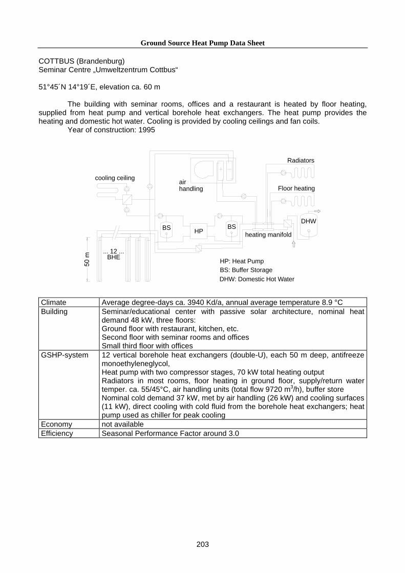
Ground Source Heat Pump Data Sheet COTTBUS (Brandenburg) Seminar Centre „Umweltzentrum Cottbus“ 51°45´N 14°19´E, elevation ca. 60 m
The building with seminar rooms, offices and a restaurant is heated by floor heating, supplied from heat pump and vertical borehole heat exchangers. The heat pump provides the heating and domestic hot water. Cooling is provided by cooling ceilings and fan coils.
Year of construction: 1995
heating manifold
air handling
Radiators
HPBS
HP: Heat PumpBS: Buffer Storage
... 12 ...BHE
BS
Floor heating
DHW
DHW: Domestic Hot Water
cooling ceiling
Climate Average degree-days ca. 3940 Kd/a, annual average temperature 8.9 °C Building Seminar/educational center with passive solar architecture, nominal heat
demand 48 kW, three floors: Ground floor with restaurant, kitchen, etc. Second floor with seminar rooms and offices Small third floor with offices
GSHP-system 12 vertical borehole heat exchangers (double-U), each 50 m deep, antifreeze monoethyleneglycol, Heat pump with two compressor stages, 70 kW total heating output Radiators in most rooms, floor heating in ground floor, supply/return water temper. ca. 55/45°C, air handling units (total flow 9720 m3/h), buffer store Nominal cold demand 37 kW, met by air handling (26 kW) and cooling surfaces (11 kW), direct cooling with cold fluid from the borehole heat exchangers; heat pump used as chiller for peak cooling
Economy not available Efficiency Seasonal Performance Factor around 3.0
203

Ground Source Heat Pump Data Sheet DELBRÜCK (Northrhine-Westfalia) 51°46´N 8°33´E, elevation ca. 95 m
New residential house, heated by floor heating, supplied from heat pump and vertical borehole heat exchangers. The heat pump provides the heating and domestic hot water. The house has high insulation standard.
Year of construction: 1998
HP
BS
HP: Heat PumpBS: Buffer Storage
Floor heating
DHW
DHW: Domestic Hot Water
2 BHE
Climate Average degree-days ca. 3500 Kd/a, annual average temperature 9.0 °C Building Residential house (new), two storeys, floor area 331 m2
GSHP-system 2 vertical borehole heat exchangers (double-U), each 99 m deep, antifreeze monoethyleneglycol, Heat pump with 13.6 kW nominal heating capacity Heating: ca. 60% of heating through floor heating with supply water temperature max. 35°C ca. 40% of heating through radiators with supply water temperature max. 50°C Buffer store in return line DHW from heat pump, through additional condensor in heat pump and DHW storage
Economy Energy cost (1999): total 666.17 € (1302.92 DM) specific 2.01 €/m2/a (3.94 DM/m2/a)
Efficiency Electric energy use for one year, between Jan. 1999 and Jan. 2000 Heat pump consumption total: 7.616 MWh Total heat delivered: 29.48 MWh for heating: 25.86 MWh for DHW: 3.62 MWh Seasonal performance factor: 3.87
204

Ground Source Heat Pump Data Sheet GÜTERSLOH (Northrhine-Westfalia) Office and store „Maas“ 51°54´N 8°23´E, elevation ca. 90 m
The building with offices and a large storage hall is heated by radiators and fan-coil-units, supplied from heat pump and vertical borehole heat exchangers. The heat pump provides the heating, and no domestic hot water. An additional gas boiler provides peak heat.
Year of construction: 1999
boiler
HP
BS
HP: Heat PumpBS: Buffer StorageHX: Heat Exchanger
engine
BSBShigh temperature (up to 80 °C)
exhaust-HX
coolingwater-HX
low temperature (50-55 °C)
Climate Average degree-days ca. 3500 Kd/a, annual average temperature 9.0°C Building Commercial building:
Office wing with three floors (900 m2) Large hall for storage and dispatching of goods (1600 m2) Nominal heat load ca. 140 kW, annual heat demand ca. 300 MWh/a
GSHP-system 8 vertical borehole heat exchangers (double-U), each 100 m deep, antifreeze monoethyleneglycol, Heat pump with 30 kW nominal heating capacity, heat pump operated by fuel oil engine, thermal output ca. 30 kW Fuel oil boiler (105 kW) for peak load (ca. 10% of annual heat)
Economy Annual cost for energy and operation (from feasibility study): heat pump fuel cost 2694 € 5269 DM oil burner (peak boiler) 870 € 1700 DM electricity (circulation etc.) 700 € 1370 DM maintenance 768 € 1503 DM total 5032 € 9842 DM
Efficiency not available
205

Ground Source Heat Pump Data Sheet HÜttenberg (Hessen) 50°30´N 8°40´E, elevation ca. 210 m
Small commercial building, heated by floor heating, supplied from heat pump and vertical borehole heat exchangers. The heat pump provides the heating, no hot water.
Year of construction: 1987
HP BS
HP: Heat PumpBS: Buffer Storage
Floor heating
5 BHE
Climate Average degree-days ca. 3500 Kd/a, annual average temperature 9.0°C Building Small commercial building (new), single floor, offices and workrooms,
manufacturing of electronic equipment, medium insulation standard (1980´s) The project is the extension of a building of about the same size, also heated by heat pump and BHE (no further data)
GSHP-system 5 vertical borehole heat exchangers (double-U), each 40 m deep, antifreeze monoethyleneglycol, Heat pump with 22 kW nominal heating capacity Floor heating with supply temperaturs ca. 35°C, buffer store no DHW by heat pump
Economy Total investment cost : 15 950 € (31 200 DM) annual cost, incl. inv.: 2611 €/a (5107 DM/a) specific energy cost, incl. inv.: 70.56 €/MWh (138 DM/MWh) (Prices 1987)
Efficiency Heat pump electr. consumption: 12.9 MWh Thermal output of heat pump: 36.9 MWh/a Monthly COP between 2.7 - 3.4 Seasonal Performance Factor 2.9 Measured between Nov. 1987 and Oct. 1988; the SPF < 3 is consistent with values measured in other plants before 1990
206

Ground Source Heat Pump Data Sheet Kochel am See (Bavaria) 47°39´N 11°22´E, elevation ca. 600 m
Three multi-family houses are heated by floor heating (in first and second floor) and radiators (in third floor), supplied by a glycol water / water heat pump and vertical borehole heat exchangers. The heat pump provides the heating and domestic hot water.
Year of construction: 1993
manifold station
9 borehole heat exchangers
technical room
heat pumpWP Si 70
heat pumpWP Si 28
radiators50 / 40
floor heating45 / 35
Only one (the largest) of 3 subsystems shown!
Climate Kochel is located at the foot of the Alps, with reference ambient air temperature
ca. -14°C Building Three multi-family houses with three floors, a total of 35 flats GSHP-system 21 vertical borehole heat exchangers (double-U), each 98 m deep, antifreeze
monoethyleneglycol, 6 heat pumps in different sizes, total 209 kW nominal heating capacity The system is divided into 3 subsystems. Each subsystem comprises 2 heat pumps of different size, the smaller one used also for domestic hot water. The size of the three subsystems and related heat pumps varies, according to the size (and heat load) of the three houses. 1 buffer storage in each subsystem, up to 1 m3. Water supply temperature to radiator circuit (third floor) 50-55°C, floor heating circuit (first and second floor) ca. 45°C.
Economy Total investment cost : ca. 127000 € (ca. 250000 DM) Efficiency no data; however, radiator circuits should be connected to the smaller heat
pump in each subsystem only. The realized plumbing urges all heat pumps to supply higher temperature than necessary most of the time.
207

Ground Source Heat Pump Data Sheet WETZLAR (Hessen) Chemical laboratory and offices „UEG“ 50°33´N 8°29´E, elevation ca. 300 m
The building with laboratories and offices is heated by radiators and fan-coil-units, supplied from heat pump and vertical borehole exchangers. The heat pump provides the heating, and no domestic hot water. An additional gas boiler provides peak heat under certain operating conditions.
Year of construction: 1992
gas boiler (70 kW)
heating manifold
central air handling
fan-coil units
heating loop south
heating loop north
Radiators
HP BS
HP: Heat PumpBS: Buffer Storage
Climate Average degree-days ca. 3500 Kd/a, annual average temperature 9.0°C Building Commercial building with two floors; private chemical laboratory:
labs for AAS, GC and other methods offices, conference room, social rooms
GSHP-system 8 vertical borehole heat exchangers (double-U), each 80 m deep, antifreeze monoethyleneglycol Heat pump with 47 kW nominal heating capacity Supply water temperature ca. 45°C, radiators in two circuits (north and south), fan coil units in some selected rooms, central air handling unit, blowing into the central corridor
continued on next page
208

Ground Source Heat Pump Data Sheet Wetzlar, continued GSHP-system (continued)
1 circulation pump for loading of buffer storage, individual circulation pump for each heating circuit the gas boiler (70 kW) is required if air handlers are at full capacity (labs need fresh air) and ambient air temperature is very low; usually 20-30 hours per yearDirect cooling with cold water from the borehole heat exchangers is provided through two cooling circuits (central air handling, fan coil units)
Economy Total investment cost : 117600 € (230000 DM) Investment cost for heat source only (no distribution) is 48 350 € Energy cost for one year (between juli 1995 and juli 1996): heating: heat pump 3675 € (116.7 MWh) gas burner 378 € (1,2 MWh) cooling: total system 223 € (50.1 MWh)
Efficiency see graph below Energy flow diagram for one year : between July 1995 and July 1996
Energy Use 100 %
Cold from the ground
19 % End
Electric powertransmission losses
Geothermal Heat 58 %Losses in
power plant 35 %
Transport to power plant
3 % Primary Energy
Energy supplied to the62 %
distribution system is 100 %
Energy1 %
(166.7 MWh)
(50,1 MWh)
23 % (46.1 MWh) (70.6 MWh)
(128.6 MWh)
209

Ground Source Heat Pump Data Sheet ÄLVSBY (Norrbotten), Sweden Hotel Storforsen 65°51´N 20°24´E, elevation ca. 200 m
The room heating in the hotel is based on floor heating, supplied from two heat pumps and vertical borehole exchangers. The heat pump provides the heating and domestic hot water up to 35 °C, with final electric heating of DHW to a temperature of 57 °C. The system also provides some cooling in summertime and acts as heat sink for condensors of freezers and refrigerators.
Year of construction: 1995
Heatpumps
(2 x 113 kW)primary circuit
Coolingmachines
refrigeratorsfreezers
33 Borehole heat exchangers each 160 m deep
HX HX
HX: Heat ExchangerE-boiler: Electric heating (peak/back-up)TD: Towel DryingHW-St.: Hot Water Storage
Recharge Cooling(room air)
secondary circ.
E-boiler
HX
Swimming pool
Floorheating
HX
cold tap water
E-boiler
warm tapwater
TDHW-St.
DHW
Climate The climate in Northern Sweden is characterized by very cold, long winters.
The location is close to the arctic circle. Average degree-days 6200 Kd/a, annual average temperature 1.7 °C
Building Hotel with a central section (restaurant, conference facilities, indoor swimming pool) and two wings with a total of 70 guestrooms. Insulation to the high standards in Sweden.
GSHP-system 33 vertical borehole heat exchangers (single-U), each 160 m deep, antifreeze monopropyleneglycol. Specific performance of BHE relatively low (28-34 W/m) due to extremely long heating period
continued on next page
210

Ground Source Heat Pump Data Sheet Storforsen, contiued GSHP-system (cont´d.)
2 water heat pumps, 113 kW nominal heating capacity each (226 kW total), heat pump refrigerant R717 (ammonia) Floor heating with supply temperature of 35°C DHW by heat pump up to 35°C, further electrically heated to 57°C Heating of water for swimming pool, possibility to recharge ground by injecting heat, condensor heat from freezers etc. rejected to ground circuit Direct cooling with brine-to-air heat exchangers in summertime
Economy not available Efficiency not available Remarks Advantages:
no local emissions (hotel in natural protection zone) low energy/operation cost (no exact data) integrated system with various uses, including space cooling in summertime
Hotel Storforsen, view from South (across Pite-älv falls, called „Storforsen“)
211