shake table testing of container cranes
TRANSCRIPT
The 14th
World Conference on Earthquake Engineering October 12-17, 2008, Beijing, China
SHAKE TABLE TESTING OF CONTAINER CRANES L.D. Jacobs
1 R. DesRoches2 and R.T. Leon
3
1 Graduate Research Assistant, Dept. of Civil and Environmental Engineering, Georgia Institute of Technology,
Atlanta, Georgia, USA Email: [email protected]
2 Professor and Associate Chair, Dept. of Civil and Environmental Engineering, Georgia Institute of Technology, Atlanta, Georgia, USA Email: [email protected]
3 Professor, Dept. of Civil and Environmental Engineering, Georgia Institute of Technology, Atlanta, Georgia,
USA Email: [email protected]
ABSTRACT: The study of the seismic behavior of container cranes is critical since recent natural hazard events have highlighted their vulnerability. This paper provides details about experiments being conducted on the six degree-of-freedom shake tables at the Structural Engineering Earthquake Simulator Laboratory at the University at Buffalo. The specimen is a 1:20 scale model constructed from steel (the prototype material). The model is designed such that the members would remain elastic during design earthquakes. The movements of the legs are tracked and strains in the portions of the crane that were determined to be vulnerable by the analyses are measured. Details of the experimental set up are presented in this paper. KEYWORDS: container crane, shake table, experimental, ports, earthquake 1. INTRODUCTION As ships continue to grow in size, so do the cranes that service them. Modern container cranes are triple the size of the original generation of cranes, making them much heavier and more vulnerable to damage from seismic events (Soderberg, 2007). During previous seismic events, three main failure modes were observed: derailment, where the wheels lift off the rails and land next to them; local buckling of the legs; and collapse of the crane (Kanayama and Kashiwazaki, 1998). It is important that any damage that a crane experiences during a seismic event be repairable because it can take more than a year to replace a crane. Two previous studies have conducted shake table experiments on container cranes. The study by Kanayama and Kashiwazaki (1998) was performed on a 1:25 scale model. The study focused on the rigid body and elastic behavior of the cranes. The crane was excited uniaxially along the direction of the boom. The study by Kanayama et. al. (1998) was performed on a 1:8 scale model. The focus of this study was on the elastic behavior of the crane. The model was excited uniaxially along the direction of the boom. During these studies, under seismic excitation, the crane moved towards the waterside, the landside legs lifted off the ground, the crane continued to move towards the waterside and the landside leg came down next to the landside crane rail. Many of the failures observed in cranes after seismic activity are due to material non-linearities, such as local buckling or yielding of the cross-sections. The previous research studies only looked at their elastic response. Research needs to be done to investigate the non-linear response of the crane and its effect on damage progression. Additionally, no studies have been conducted on cranes subjected to multi-axial excitation.
The 14th
World Conference on Earthquake Engineering October 12-17, 2008, Beijing, China 2. TEST PLAN There are several goals for the experimental work in this study. One of these goals is to understand the elastic and inelastic behavior of the container cranes. Another goal is to gather information that can be used to develop retrofit and design strategies. The final goal is to validate finite element models that can be used for fragility analyses. To achieve these goals, the testing for this study is divided into two parts. Phase I focuses on the elastic response and the uplift/rocking phenomena. Phase II focuses on the non-linear response, including local buckling and collapse. The following paragraphs provide additional details about the different phases of testing. Phase I testing is a small-scale test with a length factor of 1:20. There are several objectives for the first phase of testing. The data collected in this phase of testing will be used to validate analytical models. The information will also be used to develop preliminary fragility curves. The data will provide insight to the elastic response of the container cranes with a focus on the movement of the legs, so that critical information will be gathered on the derailment damage state. Information about the forces on the wharf deck and crane rails will be collected. An instrumentation scheme will be tested to ensure that all of the information that is required out of the larger scale test can be collected. The important response quantities that will be measured in Phase I are the boom acceleration and displacements, the vertical and horizontal displacements of the legs, the stresses in the portal joints and the distribution of the weight. Phase II testing is a large scale test, with a scale factor of 1:8. There are several objectives to this phase of testing. The data from the larger test will be used to validate the finite element models that will include non-linear material properties, and will allow for the refinement of the fragility models. The test will include movement of the legs and non-linear material responses such as cross-sections yielding and local buckling. The damage states that will be investigated are derailment, local buckling, yielding of the portal joint and collapse. Also, ideas for retrofits or new design strategies will be tested to evaluate their effectiveness. The important response quantities for the second phase of testing include boom acceleration and displacements, vertical and horizontal displacements of the legs, the stresses in the portal joints and the distribution of weight. The Phase II testing is mentioned to motivate the Phase I test, but the remainder of this paper will focus on the Phase I test. 3. SPECIMEN DESCRIPTION 3.1 Scale Factors With the focus of the Phase I test on the elastic response of the crane, a small-scale model (1:20) is sufficient to gather the necessary information. Gravity is a critical component in the uplift response, so the gravity scale factor is 1:1. Also, the prototype material, steel, is used for the specimen, so the elastic modulus scale factor is 1:1. All of the other scale factors are calculated based on the previously mentioned scale factors, and are summarized in Table 1.
Table 1: Scale Factors for 1:20 Scale Model Quantity Symbol Factor Geometric Length, l λl 20 Elastic Modulus, E λE 1 Acceleration, a λa 1 Mass, m λm 400 Time λt 4.47
The 14th
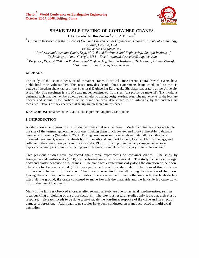
World Conference on Earthquake Engineering October 12-17, 2008, Beijing, China 3.2 Specimen Design The overall scaling of the structure leads to a specimen that is 3.35m (11 feet) tall and 6.83m (22 feet) from one end of the boom to the other. Figure 1 illustrates the dimensions of the model with the prototype dimensions in parentheses.
Figure 1: Overall dimensions of 1:20 scale model (full scale dimensions in parentheses)
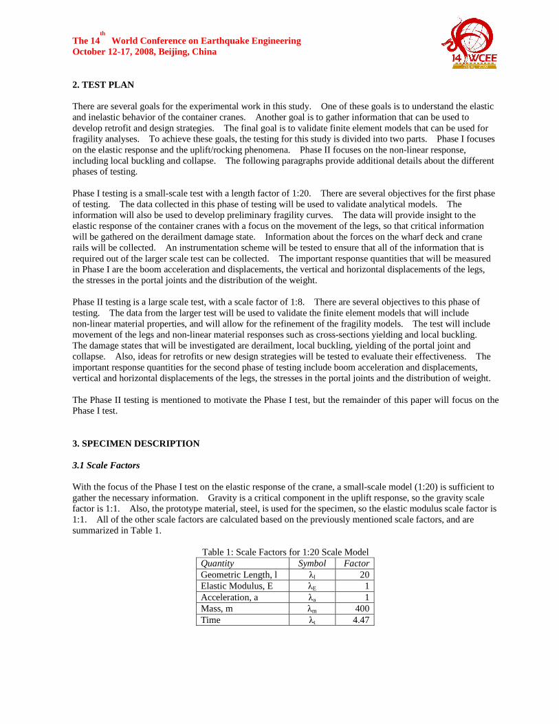
The prototype structure is constructed of built-up, stiffened box sections. The lower portion is constructed of tapered members. Due to construction concerns for the 1:20 scale model, the stiffeners are not included, but their effect on the stiffness of the members is accounted for in the moments of inertia. Also, due to concerns about preserving the material integrity of the steel plates, plate thicknesses are used that do not allow for proper area scaling. Therefore, the members are sized for bending rather than complete similitude. The stays are made from cables that are sized to have an equivalent axial stiffness to a scaled member. For this test, a small column represents the complicated system of balance beams and wheels. Figure 2 illustrates the completed specimen.
Figure 2: Completed 1:20 Scale Crane Specimen

The 14th
World Conference on Earthquake Engineering October 12-17, 2008, Beijing, China 3.3 Additional Mass The prototype crane weighs 1250 metric tons. The required weight for the model specimen is 3125 kg (6890 lbs). The specimen itself weighs 204 kg (450 lbs). The required added mass is 2921 kg (6440 lbs). The additional mass was added in three different ways. Mass is added to the frame structure in the form of strings of lead ingots. This allowed for the mass to be distributed along the length of the members. Mass is added to the columns where the crane makes contact and to the bottom most beams by filling the tubes from which they are constructed with steel pellets. Finally, mass is added to the boom by stacking steel plates in various locations along its length. Figure 3 shows examples of additional mass addition.
Figure 3: Lead Ingot Placement (left), Steel Plate Placement (right)
4. INSTRUMENTATION 4.1 Response Quantities There are several important response quantities that are measured in this study, including the accelerations and displacements of the boom, vertical and horizontal displacements of the legs, stresses in the portal joints, distribution of weight. The accelerations and displacements in the boom are important because they help characterize the modes of the dynamic response of the crane. Also, the boom is of particular interest to the crane operators, because the dynamic response affects their ability to do their job. Therefore, monitoring the boom will help to ensure that a retrofit or new design procedure does not degrade the dynamic response of the boom. Tracking the displacements of the legs allows for the characterization of the movement of the crane during seismic loading and to determine when derailment will occur. It is possible in modern container cranes that the portal joint will yield before uplift occurs. Monitoring the stresses in the portal joint will allow for determining the sequence of damage. Monitoring the distribution of weight of the crane allows for determining the distribution of forces within the crane as well as to the wharf deck and crane rails. All of these response quantities are important to know when designing structures in a port. 4.2 Instrumentation Scheme To measure the response quantities mentioned in section 4.1, an instrumentation scheme was developed that uses strain gages, load cells, accelerometers, and string potentiometers. Table 2 summarizes the instrumentation plan.

The 14th
World Conference on Earthquake Engineering October 12-17, 2008, Beijing, China
Table 2: Instrumentation Plan Summary Instrument Number of Channels Accelerometers 56 String Potentiometers 25 Strain Gages 96 Load Cells 20 TOTAL 197
Fifty-six channels of accelerometers are used. Figure 4 shows the details of the accelerometer placements. The locations where three accelerometers are indicated will have accelerometers measuring in the three perpendicular directions of the direction along the boom, perpendicular to the boom and vertically. Where only two are indicated, accelerometers will be placed perpendicular to the boom and vertically.
Figure 4: Accelerometer Instrumentation Plan for Testing of Crane
Twenty-five string potentiometers are used to measure important displacement values. Figure 5 shows the details of the potentiometer plan. The places where three potentiometers are indicated, the gages are located in the three perpendicular directions of the direction along the boom, perpendicular to the boom and vertically. Where only one is indicated, the displacement is being measured in the direction along the boom.
Figure 5: Potentiometer Instrumentation Plan for Testing of Crane
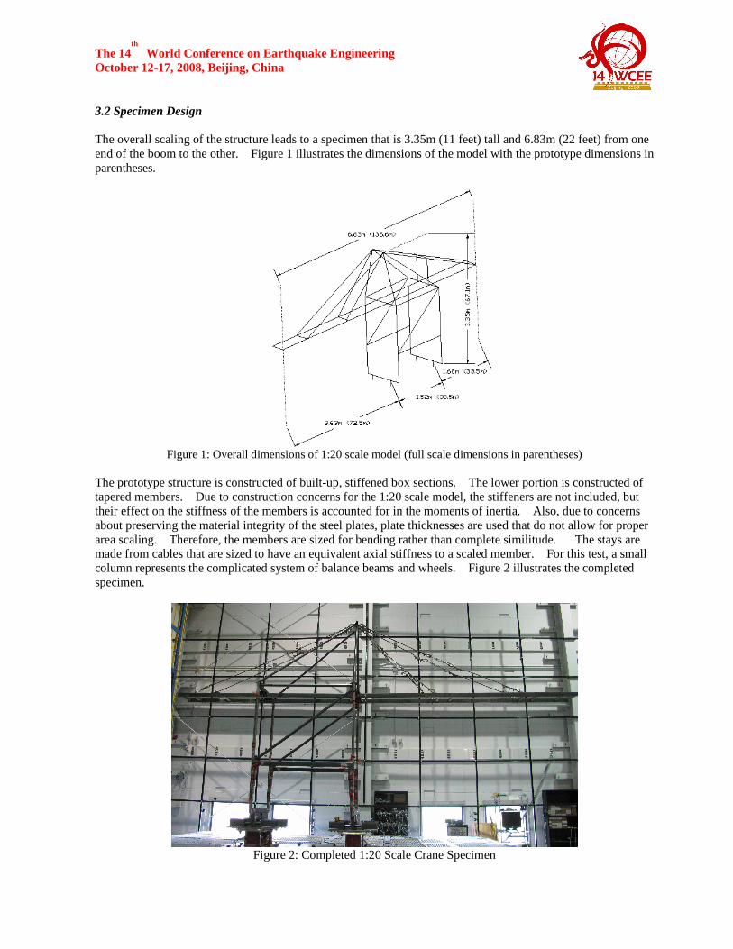
Ninety-six channels of strain gages will be applied in groups of four in the locations shown in Figure 6.
The 14th
World Conference on Earthquake Engineering October 12-17, 2008, Beijing, China
Figure 6: Strain Gage Instrumentation Plan for Testing of Crane
Four load cells are placed where the crane comes into contact with the ground. The load cells have the ability to measure axial loads, shears and moments. Additionally, the Krypton system will be used to measure the movement of the points where the crane comes into contact with the ground. The redundancy for measuring the displacements of the point of contact will ensure that some measurements for the displacements are recorded. 5. GROUND MOTIONS A suite of ground motions were chosen for this test that include design earthquakes used by the Ports of Los Angeles and Long Beach as well as recorded motions from the Port of Oakland during the Loma Prieta earthquake. The design earthquakes from the Ports of Los Angeles and Long Beach are historical earthquakes that are spectrally matched to the design spectra for the ports. From their published ground motions, two contingency level earthquakes and two operational level earthquakes are chosen. The ground motions will be scaled to amplitudes of 1/6, 1/4, 1/2, 3/4 and 1. Various combinations of the motions at the different amplitudes will be employed. The dominant response is in the direction along the boom. Therefore, the higher amplitude excitations will be used in that direction. A total of 44 trials will be performed during testing. Additionally, a low amplitude white noise will be used for the system identification phase. 6. SUMMARY The study of the behavior of container cranes is critical because recent events have highlighted the vulnerability of modern container cranes, and the replacement time for a damaged crane can be in excess of one year. This study is divided into two phases. Phase I focuses on the elastic response of the crane and lays the groundwork for a larger scale test to be conducted in the near future. Phase II focuses on the non-linear response of the crane and the progression of damage, which is previously unstudied. This paper provides details about the Phase I experiments being conducted on the six degree-of-freedom shake tables at the University at Buffalo. The goals of the test were to quantify the uplift and rocking phenomena, gain information about the elastic response of the crane and to gather information to aide in planning the large-scale test. The specimen is a 1:20 scale model constructed from steel. An instrumentation scheme is developed using accelerometers, string potentiometers, load cells and strain gages to measure the important response quantities of the boom accelerations and displacements, the vertical and horizontal displacements of the legs, the stresses in the portal joints and the distribution of weight. The specimen is subjected to a suite of ground motions that include design earthquakes from the Ports of Los Angeles and Long Beach and recorded motions from the Port of Oakland during the Loma Prieta Earthquake.
The 14th
World Conference on Earthquake Engineering October 12-17, 2008, Beijing, China ACKNOWLEDGEMENTS Benjamin Kosbab from the Georgia Institute of Technology for providing the analytical results and assistance for planning and carrying out testing. Liftech, Inc, for providing technical information about container cranes. The staff of the Structural Engineering Earthquake Simulation Laboratory at the State University of New York, University at Buffalo for their assistance in all phases of testing. Michael Sorenson, machinist at the Georgia Institute of Technology for assistance in construction of the specimen. The project was supported by the National Science Foundation through the NEESR-GC Program under Grant No.CMS-0402490.
REFERENCES Kanayama, T. and Kashiwazaki, A. (1998). A Study on the Dynamic Behavior of Container Cranes Under Strong Earthquakes. Seismic Engineering 364, 276-284. Kanayama, T., Kashiwazki, A., Shimizu, N., Nakamaura, I., and Kobayashi, N. (1998). Large Shaking Table Test of a Container Crane by Strong Ground Excitation. Seismic Engineering, 364, 243-248. Soderberg, E., and Jordan, M. (2007). Seismic Response if Jumbo Container Cranes and Design Recommendations to Limit Damage and Prevent Collapse. Proceedings of the ASCE Ports 2007 Conference, San Diego, CA. http://www.jwdliftech.com/LiftechPublications/1EGSjumbocranes.pdf