shaft excavation and cleaning - ctqp home page shaft inspector/06 - 2015... · student’s guide...
TRANSCRIPT
Student’s Guide Lesson 6-Shaft Excavation and Cleaning
Version 1 -1/15 6-1
6-1
Lesson 6
SHAFTEXCAVATION
ANDCLEANING

Student’s Guide Lesson 6-Shaft Excavation and Cleaning
Version 1 -1/15 6-2
6-2
Learning Outcomes
• Perform inspection of drilled shaft excavations for compliance to plans, tolerances and cleanliness.
• Perform visual field verification of soil/rock material for comparison to supplied soil boring data/logs.
• Sample and test slurry and fluid in the excavation.
• Calculate Elevations & Extra Shaft Lengths.
• Identify the applicable 455 Specifications

Student’s Guide Lesson 6-Shaft Excavation and Cleaning
Version 1 -1/15 6-3
6-3
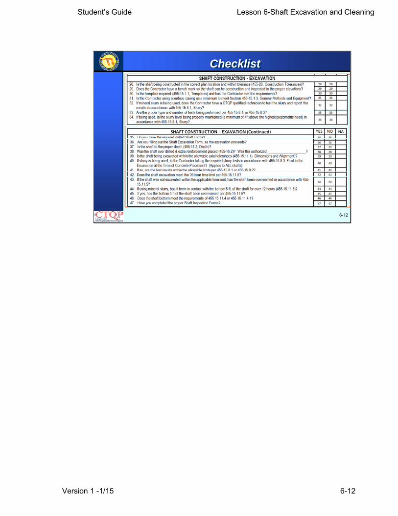
Checklist
Student’s Guide Lesson 6-Shaft Excavation and Cleaning
Version 1 -1/15 6-4
6-4
455-1.4 Vibrations on Freshly Placed Concrete(Drilled Shafts and Piers): Ensure that freshlyplaced concrete is not subjected to vibrations greaterthan 1.5 in/sec from pile driving and/or drilled shaftcasing installation sources located within the greaterdimension of three shaft diameters (measured fromthe perimeter of the shaft closest to the vibrationsource) or 30 feet (from the nearest outside edge offreshly placed concrete to the vibration source) untilthat concrete has attained its final set as defined byASTM C-403 except as required to removetemporary casings before the drilled shaft elapsedtime has expired.
455-1.4- Vibrations…Placed Concrete
Student’s Guide Lesson 6-Shaft Excavation and Cleaning
Version 1 -1/15 6-5
6-5
455-15.1 General Requirements:455-15.1.1 Templates: Provide a fixed template, adequate tomaintain shaft position and alignment during all excavationand concreting operations, when drilling from a barge. Do notuse floating templates (attached to a barge). The Engineer willnot require a template for shafts drilled on land provided theContractor demonstrates satisfactorily to the Engineer thatshaft position and alignment can be properly maintained. TheEngineer will require a fixed template, adequate to maintainshaft position and alignment during all excavation andconcreting operations, for shafts drilled on land when theContractor fails to demonstrate satisfactorily that he canproperly maintain shaft position and alignment without use ofa template.
455-15.1.1- Templates
Student’s Guide Lesson 6-Shaft Excavation and Cleaning
Version 1 -1/15 6-6
6-6
455-18 Test Holes.
The Engineer will use the construction of test holes todetermine if the methods and equipment used by theContractor are sufficient to produce a shaft excavationmeeting the requirements of the Contract Documents.During test hole excavations, the Engineer will evaluatethe ability to control dimensions and alignment ofexcavations within tolerances; to seal the casing intoimpervious materials; to control the size of the excavationunder caving conditions by the use of mineral slurry or byother means; to properly clean the completed shaftexcavation; to construct excavations in open waterareas….
455-18- Test Holes
Student’s Guide Lesson 6-Shaft Excavation and Cleaning
Version 1 -1/15 6-7
6-7
455-18 Test Holes. Continued
…. To determine the elevation of ground water; toplace reinforcing steel and concrete meeting therequirements of these Specifications within theprescribed time frame; and to execute any othernecessary construction operation. Revise themethods and equipment as necessary at any timeduring the construction of the test hole whenunable to satisfactorily carry out any of thenecessary operations described above or whenunable to control the dimensions and alignment ofthe shaft excavation within tolerances….
455-18- Test Holes
Student’s Guide Lesson 6-Shaft Excavation and Cleaning
Version 1 -1/15 6-8
455-18 Test Holes. Continued
….Drill test holes out of permanent position at thelocation shown in the plans or as directed by theEngineer. Ensure the diameter and depth of the testhole or holes are the same diameter and maximumdepth as the production drilled shafts. Reinforce thetest hole unless otherwise directed in the ContractDocuments. Fill the test hole with concrete in the samemanner production drilled shafts will be constructed.Backfill test holes which are not filled with concretewith suitable soil in a manner satisfactory to theEngineer. Leave concreted test holes in place, exceptremove the top of the shaft to a depth of 2 feet belowthe ground line….
6-8
455-18- Test Holes
Student’s Guide Lesson 6-Shaft Excavation and Cleaning
Version 1 -1/15 6-9
6-9
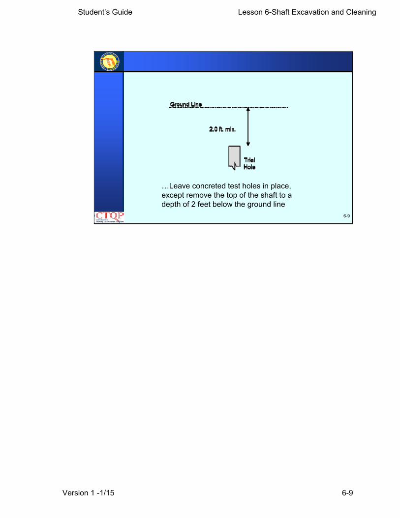
…Leave concreted test holes in place, except remove the top of the shaft to a depth of 2 feet below the ground line
Student’s Guide Lesson 6-Shaft Excavation and Cleaning
Version 1 -1/15 6-10
6-10
455-18- Test Holes
455-18 Test Holes. Continued
…. Use the same procedure for shafts constructed inwater. Restore the disturbed areas at the sites of testholes drilled out of position as nearly as practical totheir original condition. When the Contractor fails todemonstrate to the Engineer the adequacy of hismethods or equipment, and alterations are required,make appropriate modifications and provide additionaltest holes at no expense to the Department. Includethe cost of all test holes in the cost of the DrilledShafts. Make no changes in methods or equipmentafter initial approval without the consent of theEngineer.…

Student’s Guide Lesson 6-Shaft Excavation and Cleaning
Version 1 -1/15 6-11
6-11
455-18- Test Holes
455-18 Test Holes. Continued
…A separate test hole is not required for drilled shaftsinstalled under mast arms, cantilever signs, overheadtruss signs, high mast light poles or othermiscellaneous structures. The first production shaft willserve as a test hole for determining acceptability of theinstallation method.
Student’s Guide Lesson 6-Shaft Excavation and Cleaning
Version 1 -1/15 6-12
6-12
Checklist
Student’s Guide Lesson 6-Shaft Excavation and Cleaning
Version 1 -1/15 6-13
455-15.10.1 General: All shaft excavation isUnclassified Shaft Excavation. The Engineer willrequire Drilled Shaft Sidewall Overreaming wheninspections show it to be necessary. These termsare defined in 455-15.10.2, 455-15.10.3, and 455-15.10.4, respectively.
Use excavation and drilling equipment havingadequate capacity, including power, torque, andcrowd (downthrust), and excavation andoverreaming tools of adequate design, size, andstrength to perform the work shown in the plans ordescribed herein.….
6-13
455-15.10.1- General

Student’s Guide Lesson 6-Shaft Excavation and Cleaning
Version 1 -1/15 6-14
6-14
455-15.10.1 General:Continued
…When the material encountered cannot be drilledusing conventional earth augers and/or underreamingtools, provide special drilling equipment, including butnot limited to rock augers, core barrels, rock tools, airtools, blasting materials, and other equipment asnecessary to continue the shaft excavation to the sizeand depth required. In the event blasting isnecessary, obtain all necessary permits. TheContractor is responsible for the effects of blasting onalready completed work and adjacent structures. TheEngineer must approve all blasting.
455-15.10.1- General

Student’s Guide Lesson 6-Shaft Excavation and Cleaning
Version 1 -1/15 6-15
6-15
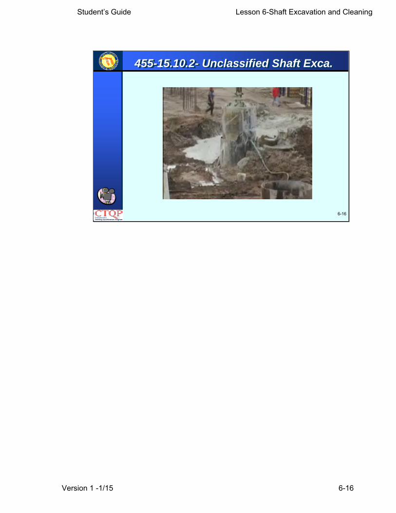
455-15.10.2 Unclassified Shaft Excavation:Unclassified Shaft Excavation is defined as all processesrequired to excavate a drilled shaft of the dimensionsshown in the Contract Documents to the depth indicatedin the plans plus 15 feet or plus 3 shaft diameters,whichever is deeper, completed and accepted. Include inthe work all shaft excavation, whether the materialencountered is soil, rock, weathered rock, stone, naturalor man-made obstructions, or materials of otherdescriptions.
455-15.10.2- Unclassified Shaft Exca.
Student’s Guide Lesson 6-Shaft Excavation and Cleaning
Version 1 -1/15 6-16
6-16
455-15.10.2- Unclassified Shaft Exca.

Student’s Guide Lesson 6-Shaft Excavation and Cleaning
Version 1 -1/15 6-17
6-17
455-15.10.3 Unclassified Extra Depth Excavation:Unclassified Extra Depth Excavation is defined as allprocesses required to excavate a drilled shaft of plandimensions which is deeper than the limits defined asUnclassified Shaft Excavation.
455-15.10.2- Unclass. Extra Depth Ex.

Student’s Guide Lesson 6-Shaft Excavation and Cleaning
Version 1 -1/15 6-18
6-18
455-15.10.4- D. S. Sidewall Overreaming
455-15.10.4 Drilled Shaft Sidewall Overreaming: DrilledShaft Sidewall Overreaming is defined as the unclassifiedexcavation required to roughen its surface or to enlarge thedrilled shaft diameter due to softening of the sidewalls or toremove excessive buildup of slurry cake when slurry isused. Increase the shaft radius a minimum of 1/2 inch anda maximum of 3 inches by overreaming. The Contractormay accomplish overreaming with a grooving tool,overreaming bucket, or other approved equipment.

Student’s Guide Lesson 6-Shaft Excavation and Cleaning
Version 1 -1/15 6-19
6-19
455-15.7 Casings:
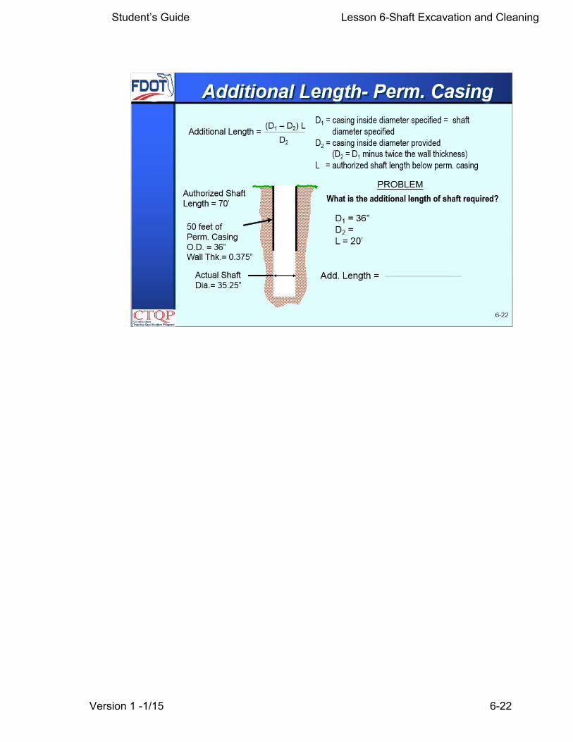
The Engineer will allow the Contractor to supplycasing with an outside diameter equal to thespecified shaft diameter (O.D. casing) provided hesupplies additional shaft length at the shaft tip.Determine the additional length of shaft required bythe following relationship:
455-15.7- Casing
Student’s Guide Lesson 6-Shaft Excavation and Cleaning
Version 1 -1/15 6-20
6-20
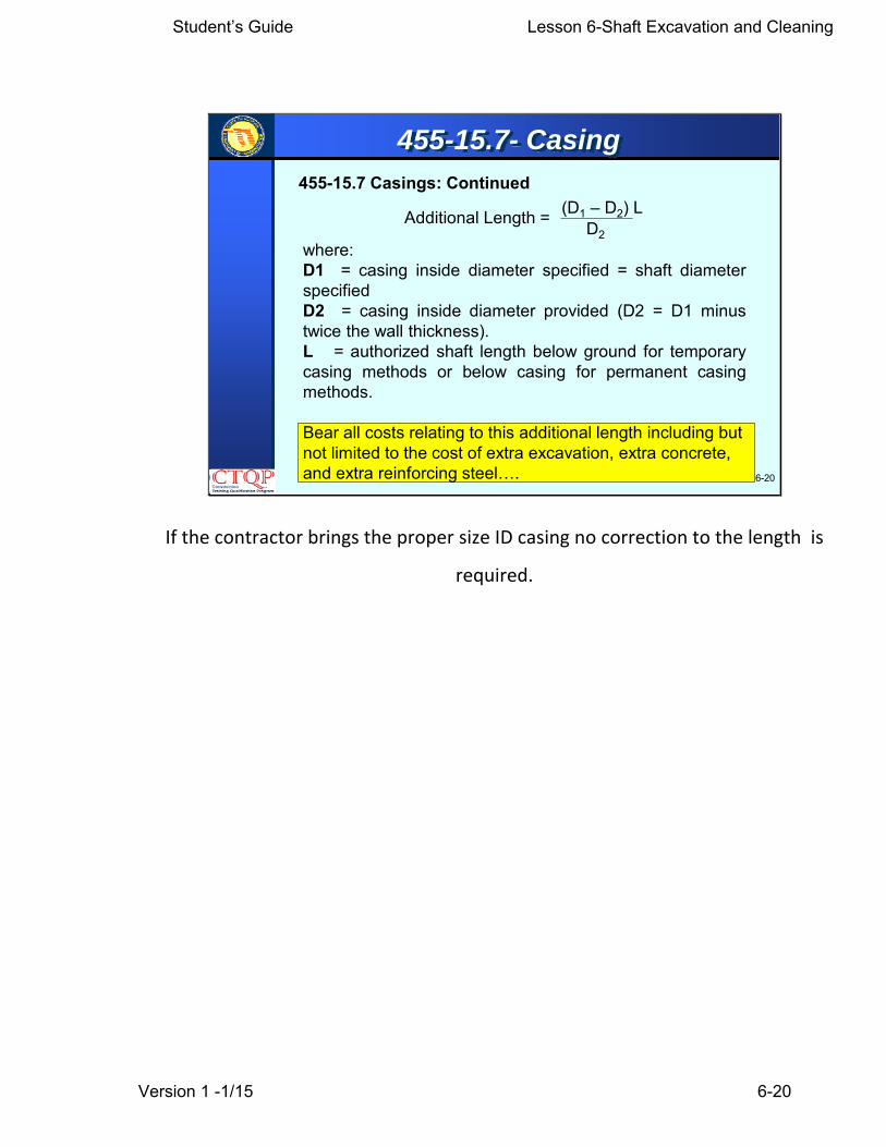
where:D1 = casing inside diameter specified = shaft diameterspecifiedD2 = casing inside diameter provided (D2 = D1 minustwice the wall thickness).L = authorized shaft length below ground for temporarycasing methods or below casing for permanent casingmethods.
Bear all costs relating to this additional length including but not limited to the cost of extra excavation, extra concrete, and extra reinforcing steel….
455-15.7 Casings: Continued
Additional Length = (D1 – D2) LD2
455-15.7- Casing
If the contractor brings the proper size ID casing no correction to the length is
required.

Student’s Guide Lesson 6-Shaft Excavation and Cleaning
Version 1 -1/15 6-21
Student’s Guide Lesson 6-Shaft Excavation and Cleaning
Version 1 -1/15 6-22
Student’s Guide Lesson 6-Shaft Excavation and Cleaning
Version 1 -1/15 6-23
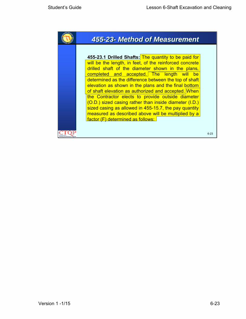
455-23.1 Drilled Shafts: The quantity to be paid forwill be the length, in feet, of the reinforced concretedrilled shaft of the diameter shown in the plans,completed and accepted. The length will bedetermined as the difference between the top of shaftelevation as shown in the plans and the final bottomof shaft elevation as authorized and accepted. Whenthe Contractor elects to provide outside diameter(O.D.) sized casing rather than inside diameter (I.D.)sized casing as allowed in 455-15.7, the pay quantitymeasured as described above will be multiplied by afactor (F) determined as follows:
455-23- Method of Measurement
6-23

Student’s Guide Lesson 6-Shaft Excavation and Cleaning
Version 1 -1/15 6-24
455-23- Method of Measurement
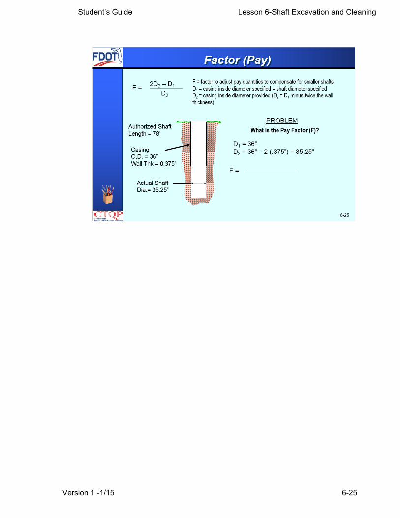
where:F = factor to adjust pay quantities to compensate for smaller shafts
D1 = casing inside diameter specified = shaft diameter specified
D2 = casing inside diameter provided (D2 = D1 minus twice the wall thickness)
F = 2D2 – D1D2
6-24
Note that there is no length involved; only diameters in this calculation
This factor can never be greater than 1.0.
Student’s Guide Lesson 6-Shaft Excavation and Cleaning
Version 1 -1/15 6-25
Student’s Guide Lesson 6-Shaft Excavation and Cleaning
Version 1 -1/15 6-26
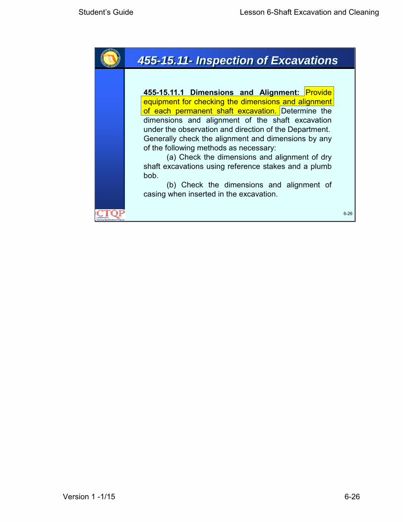
455-15.11.1 Dimensions and Alignment: Provideequipment for checking the dimensions and alignmentof each permanent shaft excavation. Determine thedimensions and alignment of the shaft excavationunder the observation and direction of the Department.Generally check the alignment and dimensions by anyof the following methods as necessary:
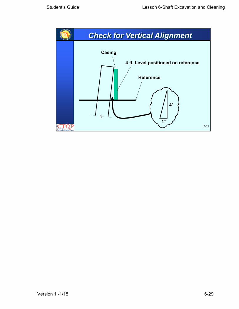
(a) Check the dimensions and alignment of dryshaft excavations using reference stakes and a plumbbob.
(b) Check the dimensions and alignment ofcasing when inserted in the excavation.
6-26
455-15.11- Inspection of Excavations

Student’s Guide Lesson 6-Shaft Excavation and Cleaning
Version 1 -1/15 6-27
6-27
455-15.11- Inspection of Excavations
455-15.11.1 Dimensions and Alignment: Continued
(c) Insert a casing in shaft excavations temporarily foralignment and dimension checks.
(d) Insert a rigid rod or pipe assembly with several 90-degree offsets equal to the shaft diameter into the shaftexcavation for alignment and dimension checks.
Insert any casing, rod or pipe assembly, or other deviceused to check dimensions and alignment into theexcavation to full depth.
The depth of the shaft during drilling is usually referenced to appropriate marks on the Kelly bar or other suitable methods.

Student’s Guide Lesson 6-Shaft Excavation and Cleaning
Version 1 -1/15 6-28
6-28
¼”
1’
Vertical Alignment
Student’s Guide Lesson 6-Shaft Excavation and Cleaning
Version 1 -1/15 6-29
6-291”
4’
Casing
Reference
4 ft. Level positioned on reference
Check for Vertical Alignment
Student’s Guide Lesson 6-Shaft Excavation and Cleaning
Version 1 -1/15 6-30
6-30
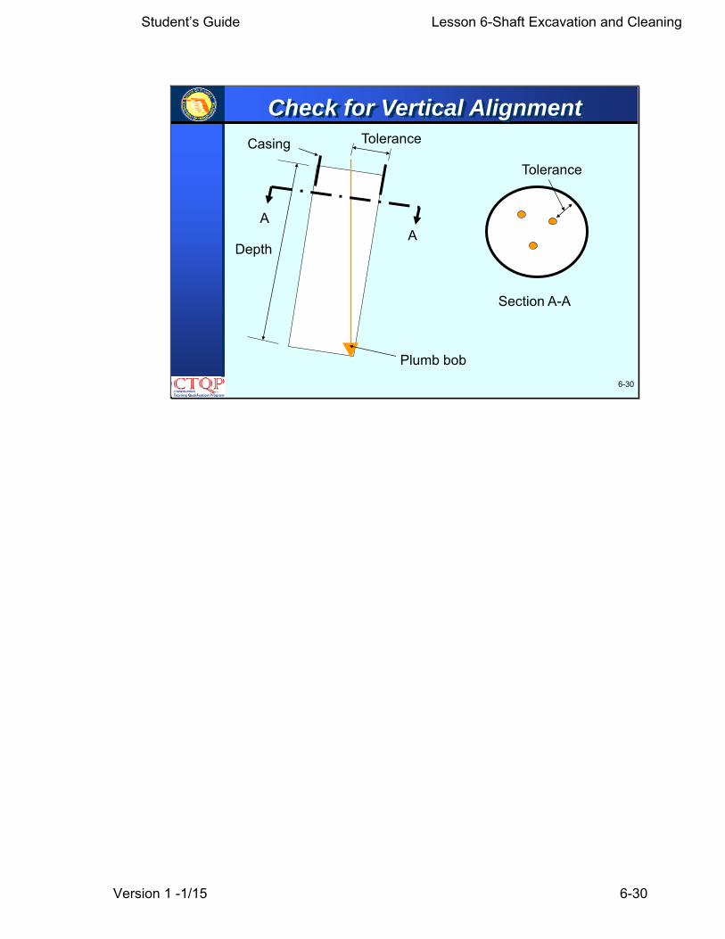
Depth
Casing
Plumb bob
Tolerance
AA
Section A-A
Tolerance
Check for Vertical Alignment
Student’s Guide Lesson 6-Shaft Excavation and Cleaning
Version 1 -1/15 6-31
6-31
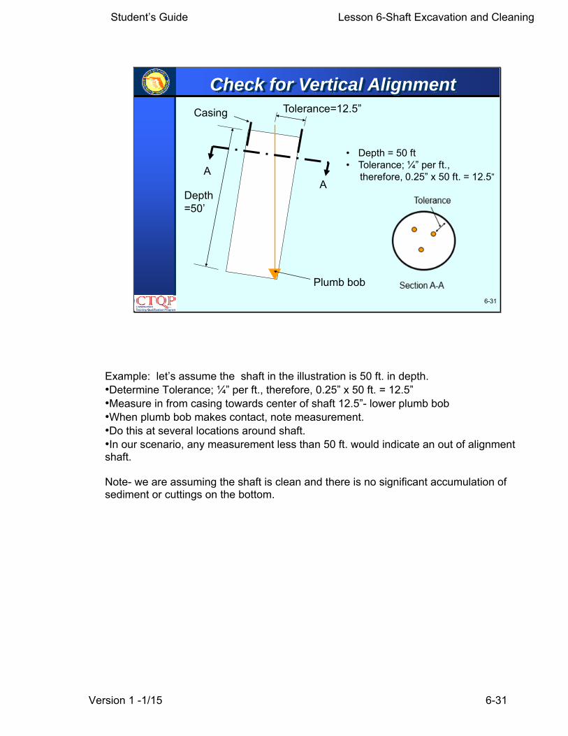
Depth=50’
Casing
Plumb bob
Tolerance=12.5”
AA
Check for Vertical Alignment
• Depth = 50 ft• Tolerance; ¼” per ft.,
therefore, 0.25” x 50 ft. = 12.5”
Example: let’s assume the shaft in the illustration is 50 ft. in depth. •Determine Tolerance; ¼” per ft., therefore, 0.25” x 50 ft. = 12.5” •Measure in from casing towards center of shaft 12.5”- lower plumb bob •When plumb bob makes contact, note measurement. •Do this at several locations around shaft. •In our scenario, any measurement less than 50 ft. would indicate an out of alignment shaft. Note- we are assuming the shaft is clean and there is no significant accumulation of sediment or cuttings on the bottom.
Student’s Guide Lesson 6-Shaft Excavation and Cleaning
Version 1 -1/15 6-32
6-32
The Inspector’s responsibilities are thesame during the Test Shaft Installationas in the Production Shaft installation.
Inspector Duties for Test Hole

Student’s Guide Lesson 6-Shaft Excavation and Cleaning
Version 1 -1/15 6-33
6-33
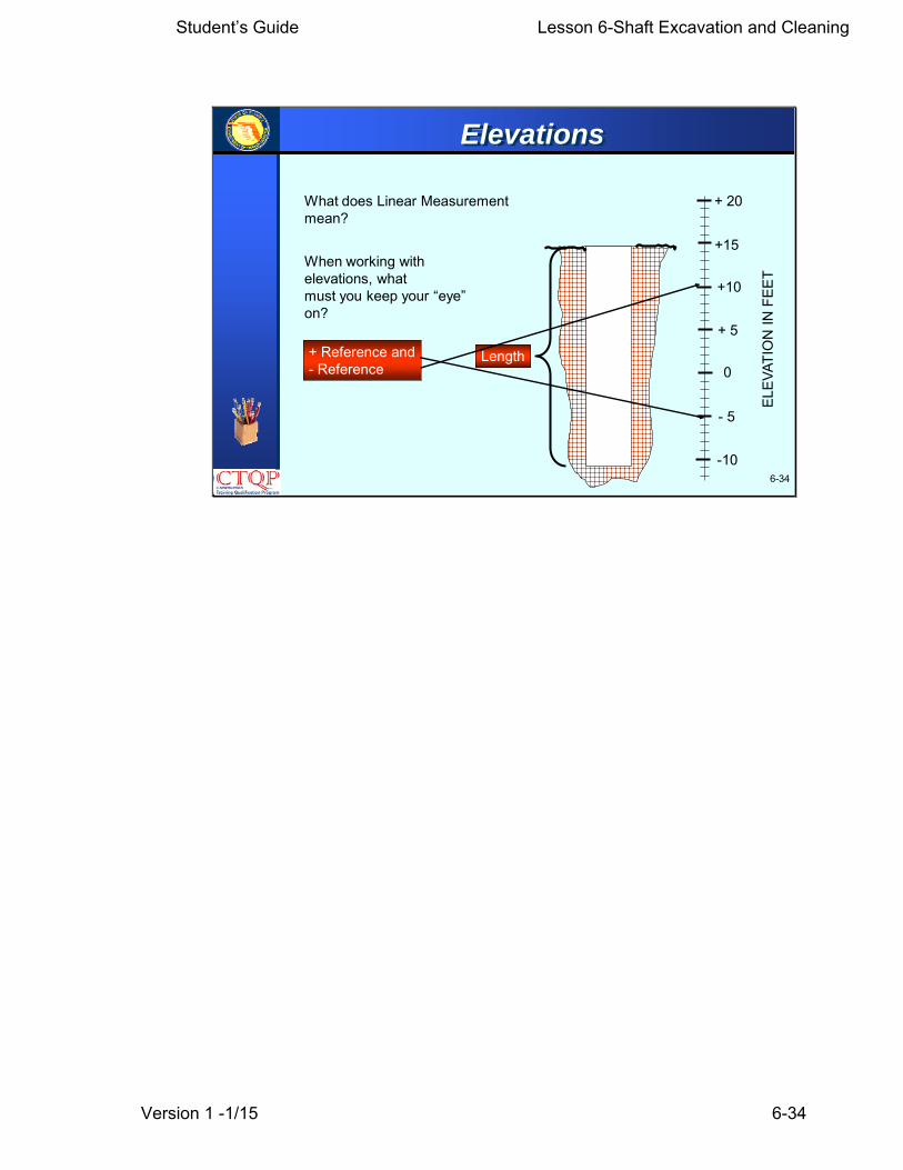
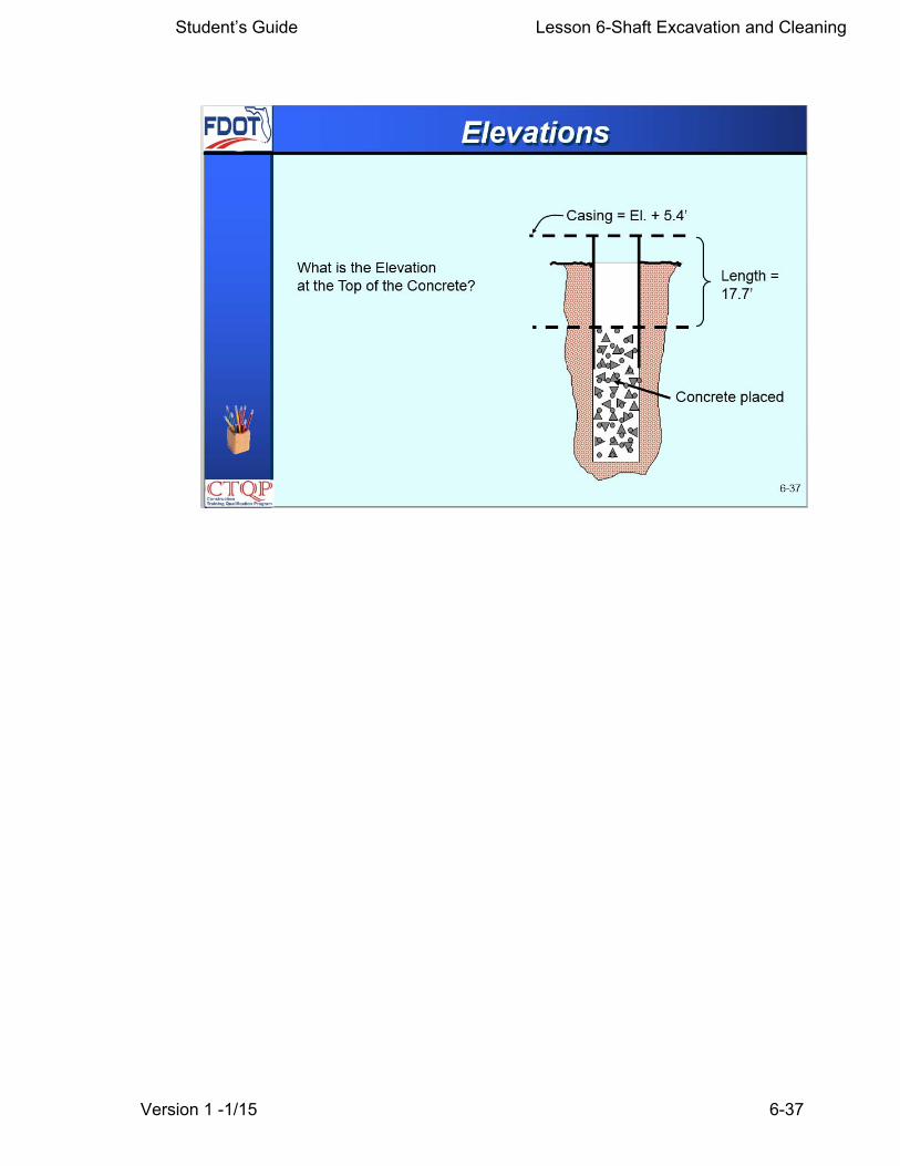
Elevations
Was this an Englishor Metric job?
Student’s Guide Lesson 6-Shaft Excavation and Cleaning
Version 1 -1/15 6-34
6-34
What does Linear Measurementmean?
+ 20
+15
+10
+ 5
0
- 5
-10
ELEV
ATIO
N IN
FEE
T
Length
When working with elevations, whatmust you keep your “eye” on?
+ Reference and- Reference
Elevations

Student’s Guide Lesson 6-Shaft Excavation and Cleaning
Version 1 -1/15 6-35

Student’s Guide Lesson 6-Shaft Excavation and Cleaning
Version 1 -1/15 6-36
Student’s Guide Lesson 6-Shaft Excavation and Cleaning
Version 1 -1/15 6-37
Student’s Guide Lesson 6-Shaft Excavation and Cleaning
Version 1 -1/15 6-38
6-38
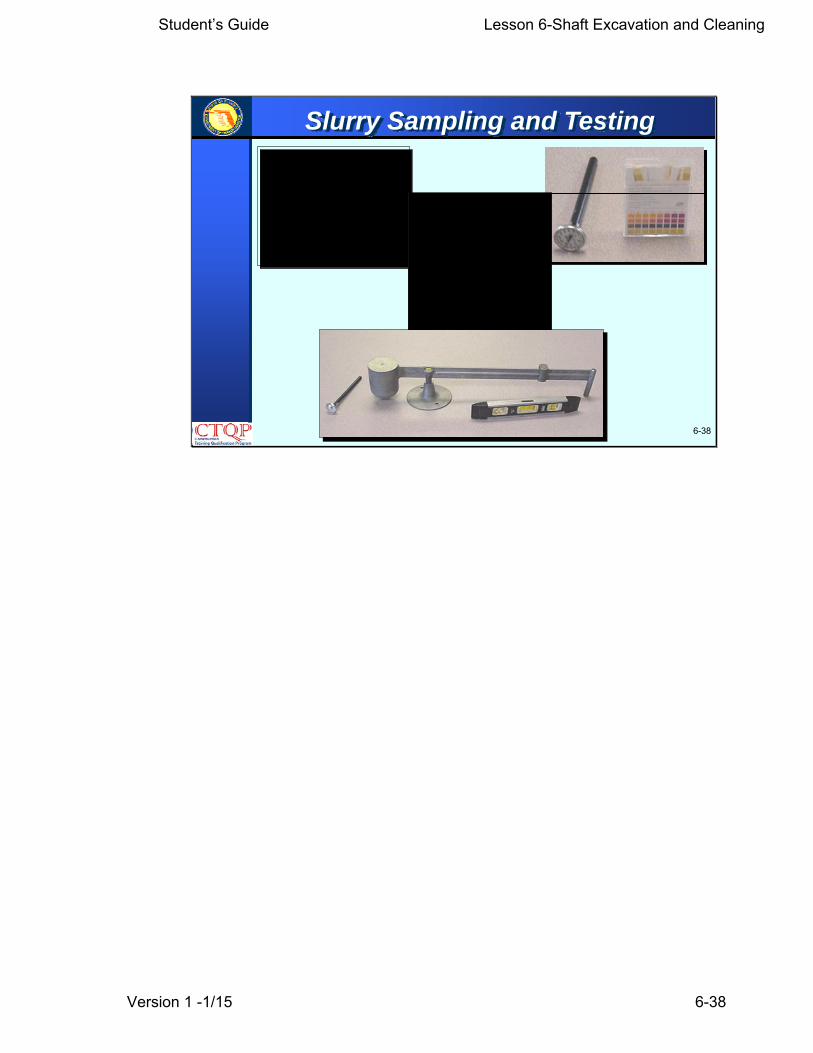
Slurry Sampling and Testing
Student’s Guide Lesson 6-Shaft Excavation and Cleaning
Version 1 -1/15 6-39
6-39
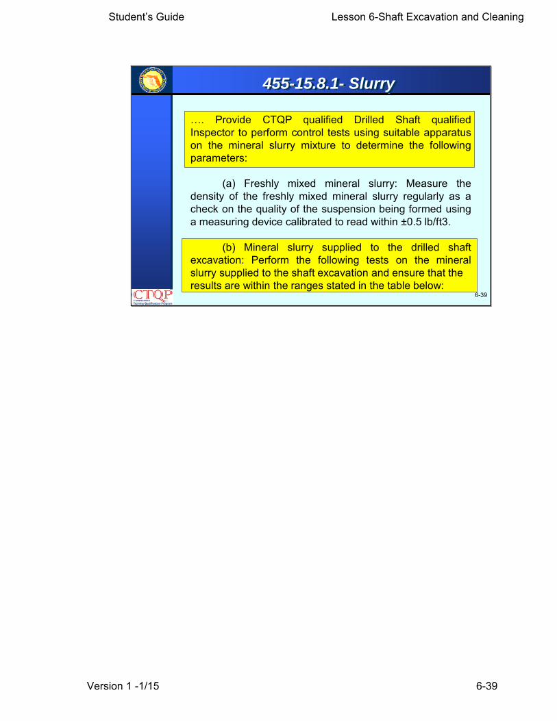
455-15.8.1- Slurry
…. Provide CTQP qualified Drilled Shaft qualifiedInspector to perform control tests using suitable apparatuson the mineral slurry mixture to determine the followingparameters:
(a) Freshly mixed mineral slurry: Measure thedensity of the freshly mixed mineral slurry regularly as acheck on the quality of the suspension being formed usinga measuring device calibrated to read within ±0.5 lb/ft3.
(b) Mineral slurry supplied to the drilled shaftexcavation: Perform the following tests on the mineralslurry supplied to the shaft excavation and ensure that theresults are within the ranges stated in the table below:

Student’s Guide Lesson 6-Shaft Excavation and Cleaning
Version 1 -1/15 6-40
6-40
Item to be measured Range of Results at 680 F Test Method
Slurry Tests
Density 64 to 73 lb/ft3 (in fresh water env.)66 to 75 lb/ft3 (in salt water env.)
Mud density balanceFM 8-RP13B-1
Viscosity
pH
30 to 40 seconds Marsh Cone MethodFM 8-RP13B-2
8 to 11Electric pH meter or pH indicator paper strips
FM 8-RP13B-4
Sand Content 4% or less FM 8-RP13B-3
455-15.8.1- Slurry

Student’s Guide Lesson 6-Shaft Excavation and Cleaning
Version 1 -1/15 6-41
6-41
• Also known as Marsh Funnel Test
• Measures the flow rate(i.e. consistency)
• FM 8-RP13B-2
Viscosity Test
The viscosity test is also known as the Marsh Funnel. It measures the flow rate. This tests must be performed in accordance with the Florida Method FM 8-RP13B-2. This test is performed on the fluid and consists basically of measuring the time required for a prescribe d amount of slurr y, one q uarter of a gal lon, to p ass through a plastic funnel with a standar d size orifi ce. The fu nnel is hel d in an upright position with th e outlet sealed by one’s hand or finger. The test sample is poured through the screen at the top of the funnel until the mud level just reaches the underside of the screen. A stop watch is used t o measure the time for a prescribed amount of mud to exit the funnel with the results measured in seconds. As a comp arative number, clear wat er would generally have a test result of 26 seconds, which is a good check on the equipment.
Student’s Guide Lesson 6-Shaft Excavation and Cleaning
Version 1 -1/15 6-42
6-42
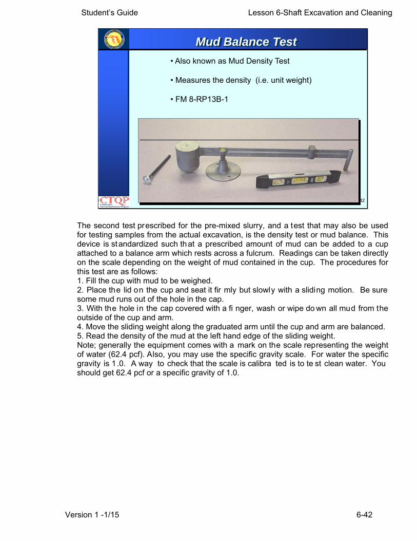
• Also known as Mud Density Test
• Measures the density (i.e. unit weight)
• FM 8-RP13B-1
Mud Balance Test
The second test prescribed for the pre-mixed slurry, and a test that may also be used for testing samples from the actual excavation, is the density test or mud balance. This device is standardized such that a prescribed amount of mud can be added to a cup attached to a balance arm which rests across a fulcrum. Readings can be taken directly on the scale depending on the weight of mud contained in the cup. The procedures for this test are as follows: 1. Fill the cup with mud to be weighed. 2. Place the lid on the cup and seat it fir mly but slowly with a sliding motion. Be sure some mud runs out of the hole in the cap. 3. With the hole in the cap covered with a fi nger, wash or wipe do wn all mud from the outside of the cup and arm. 4. Move the sliding weight along the graduated arm until the cup and arm are balanced. 5. Read the density of the mud at the left hand edge of the sliding weight. Note; generally the equipment comes with a mark on the scale representing the weight of water (62.4 pcf). Also, you may use the specific gravity scale. For water the specific gravity is 1 .0. A way to check that the scale is calibra ted is to te st clean water. You should get 62.4 pcf or a specific gravity of 1.0.

Student’s Guide Lesson 6-Shaft Excavation and Cleaning
Version 1 -1/15 6-43
6-43
• For determining the acidity and alkalinity contentof the slurry mix
• Reported as number value (1-14)
• FM 8-RP13B-4
pH Test
• pH is a test to determine determining the acidity and alkalinity content of the slurry
mix
• It is reported as number value (1-14)
• pH strips may be used to estimate this value.

Student’s Guide Lesson 6-Shaft Excavation and Cleaning
Version 1 -1/15 6-44
6-44
• For determining the sandcontent of the slurry mix
• Reported in volume percent
• FM 8-RP13B-3
Sand Content Test
A more co mplex test is requir ed when the sand co ntent must be d etermined. Th e equipment required for this test consists of a 200 mesh sieve, a small funnel and a sand content tube. The test procedure is prescribed as follows: 1. Fill the sand content tube to the indicated mark with mud. Add wat er to next mark. Close mouth of the tube and shake vigorously . 2. Pour the mixture onto the clean, wet screen. Discard the liquid passing through the screen. Add more water to the tube, shake, and again pour onto the screen. Repeat until the wash water passes through clear. Wash the sand retained on the screen to free it of any remaining mud. 3. Fit the funnel upside down over the top of the screen. Slowly invert the assembly and insert the tip of the funnel into the mouth of the tube. Wash the sand int o the tube by spraying a fi ne spray of w ater through the screen. (Tappi ng on th e side of th e screen with a spa tula handle, may facilitate this process). Allow the sand to settle. From the gradations on the tube, read the volume percent of the sand. 4. Report the sand content of the mud in volume percent.

Student’s Guide Lesson 6-Shaft Excavation and Cleaning
Version 1 -1/15 6-45
6-45
Pre-mixed vs Fluid in Excavation
Fluid in the excavation
Slurry
Slurry refers to the “pre-mixed” slurry or the slurry that has not been introduced into the hole. Fluid in the excavation refers to the slurry or fluid in the shaft excavation.
Student’s Guide Lesson 6-Shaft Excavation and Cleaning
Version 1 -1/15 6-46
6-46
455-15.8.1, Slurry: Continued
…The Contractor may adjust the limits in the above tablewhen field conditions warrant as successfullydemonstrated in a Test Hole or with other methodsapproved by the Engineer. The Engineer must approveall changes in writing before the Contractor can continueto use them.…
455-15.8.1- Pre-mixed Slurry

Student’s Guide Lesson 6-Shaft Excavation and Cleaning
Version 1 -1/15 6-47
6-47
455-15.8.1, Slurry: Continued
…Perform tests to determine density, viscosity, and pHvalue to establish a consistent working pattern, takinginto account the mixing process and blending of freshlymixed mineral slurry and previously used mineral slurry.Perform a minimum of four sets of tests to determinedensity, viscosity, and pH value during the first 8 hoursmineral slurry is in use.…
455-15.8.1- Slurry
Student’s Guide Lesson 6-Shaft Excavation and Cleaning
Version 1 -1/15 6-48
6-48
455-15.8.1, Slurry: Continued
…When the results show consistent behavior,discontinue the tests for pH value, and only carry outtests to determine density and viscosity during eachfour hours mineral slurry is in use. If the consistentworking pattern changes, reintroduce the additionaltests for pH value for the time required to establishconsistency of the test values within the requiredparameters.…
455-15.8.1- Slurry

Student’s Guide Lesson 6-Shaft Excavation and Cleaning
Version 1 -1/15 6-49
6-49
455-15.8.1, Slurry: Continued
(c) The Department may perform comparison tests asdetermined necessary during the mineral slurryoperations.
455-15.8.1- Slurry
Student’s Guide Lesson 6-Shaft Excavation and Cleaning
Version 1 -1/15 6-50
6-50
455-15.8.1, Slurry: Continued
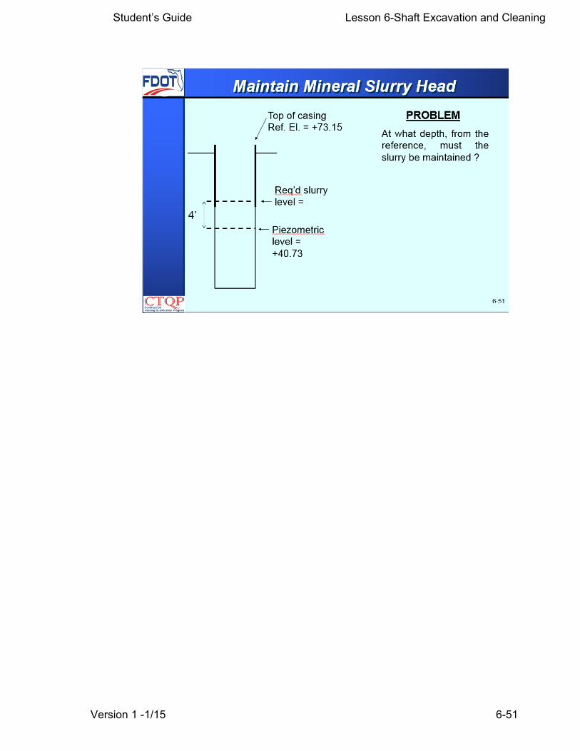
…During construction, maintain the level of mineral slurryin the shaft excavation within the excavation and at alevel not less than 4 feet above the highest expectedpiezometric water pressure along the depth of a shaft.
At any time the wet construction method ofstabilizing excavations fails, in the opinion of theEngineer, to produce the desired final result, discontinuethis method of construction, and propose modifications inprocedure or alternate means of construction forapproval.
455-15.8.1- Slurry
Piezometric level refers in the water level that would be observed in an open well or in a piezometer. In an artesian aquifer the water level may be significantly higher than the water level even higher than the ground level. In a typical normal unconfined aquifer the water table is the piezometric level
Student’s Guide Lesson 6-Shaft Excavation and Cleaning
Version 1 -1/15 6-51

Student’s Guide Lesson 6-Shaft Excavation and Cleaning
Version 1 -1/15 6-52
6-52
455-15.8.2 Polymer Slurry … Misc. Struc.
455-15.8.2 Polymer Slurry For Shafts ForMiscellaneous Structures:
…. Perform the following tests on the polymer slurry in theshaft excavation and ensure that the results aremaintained within the ranges stated in the table below:
Polymer Slurry For Shafts For Miscellaneous Structures:
The Department allows polymers that meet certain conditions to be used in shafts for miscellaneous structures only. The same tests performed for mineral slurry are performed.
Student’s Guide Lesson 6-Shaft Excavation and Cleaning
Version 1 -1/15 6-53
6-53
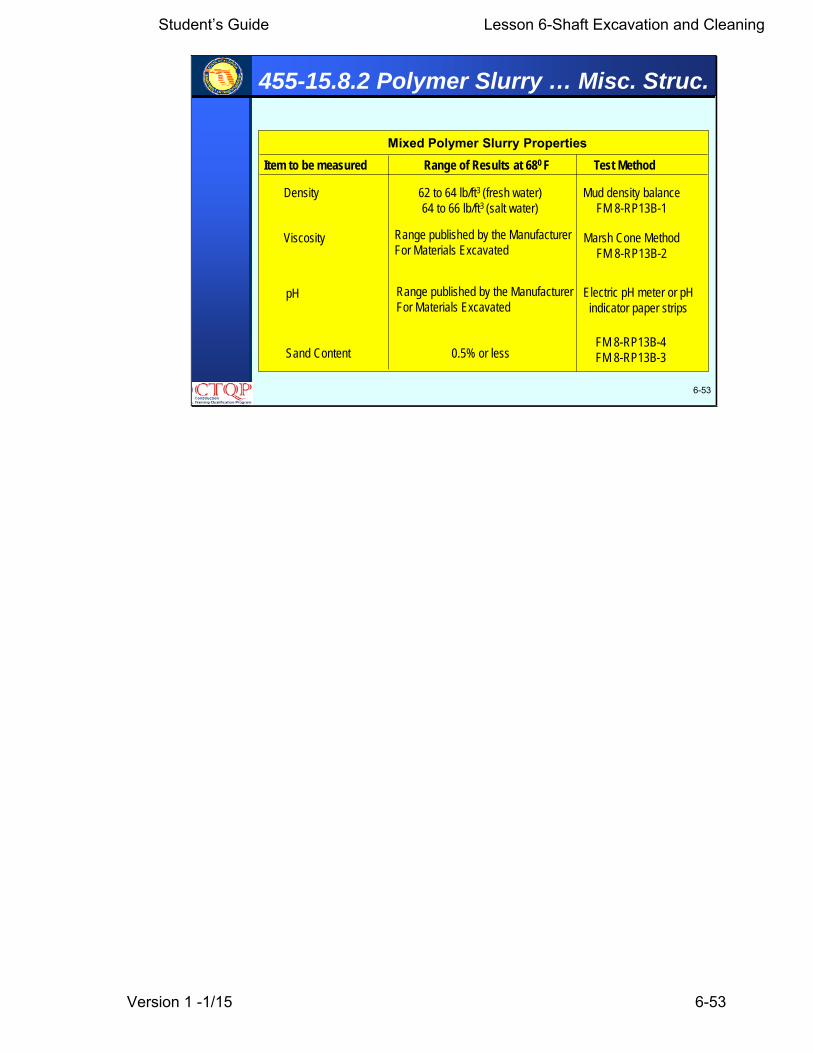
455-15.8.2 Polymer Slurry … Misc. Struc.
Item to be measured Range of Results at 680 F Test Method
Mixed Polymer Slurry Properties
Density 62 to 64 lb/ft3 (fresh water)64 to 66 lb/ft3 (salt water)
Mud density balanceFM 8-RP13B-1
Viscosity
pH
Range published by the ManufacturerFor Materials Excavated
Marsh Cone MethodFM 8-RP13B-2
Electric pH meter or pH indicator paper strips
Sand Content 0.5% or lessFM 8-RP13B-4FM 8-RP13B-3
Range published by the ManufacturerFor Materials Excavated

Student’s Guide Lesson 6-Shaft Excavation and Cleaning
Version 1 -1/15 6-54
6-54
455-15.8.2 Polymer Slurry For Shafts ForMiscellaneous Structures: Continued
…..During construction, maintain the level of the slurryat a height sufficient to prevent caving of the hole. Atany time the wet construction method of stabilizingexcavations fails, in the opinion of the Engineer, toproduce the desired final result, discontinue thismethod of construction, and propose modifications inprocedure or alternate means of construction forapproval.
455-15.8.2 Polymer Slurry … Misc. Struc.
Student’s Guide Lesson 6-Shaft Excavation and Cleaning
Version 1 -1/15 6-55
6-55
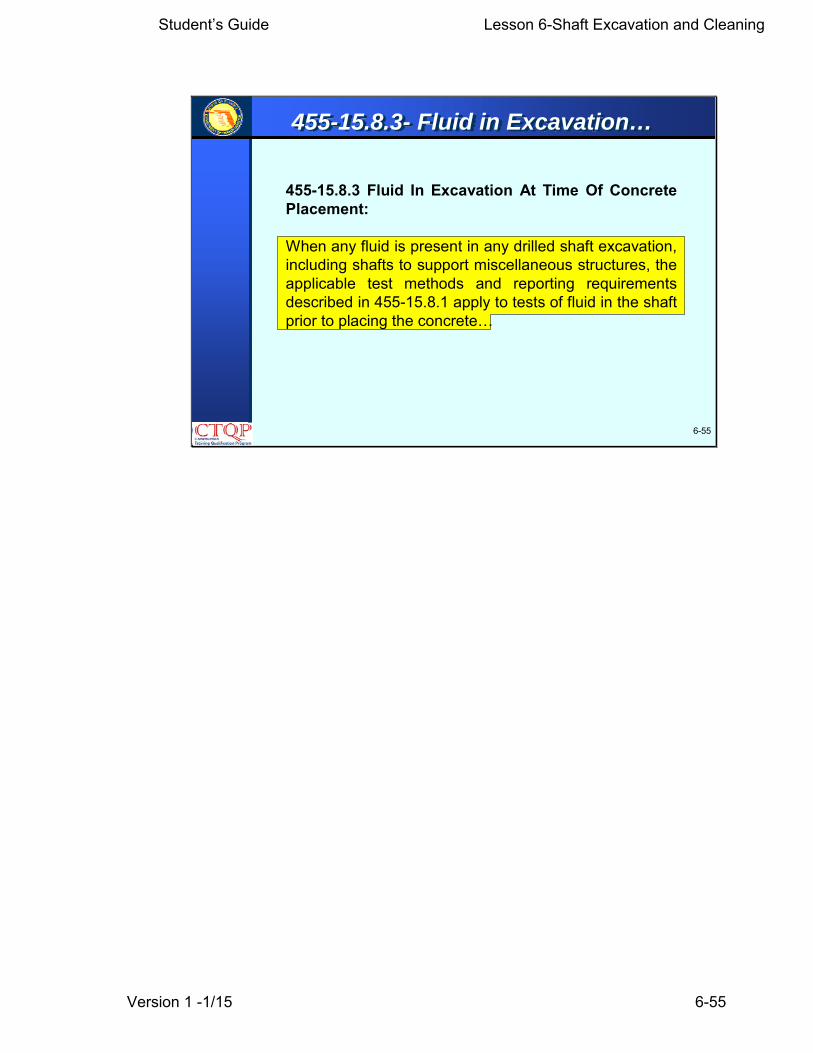
455-15.8.3 Fluid In Excavation At Time Of ConcretePlacement:
When any fluid is present in any drilled shaft excavation,including shafts to support miscellaneous structures, theapplicable test methods and reporting requirementsdescribed in 455-15.8.1 apply to tests of fluid in the shaftprior to placing the concrete…
455-15.8.3- Fluid in Excavation…

Student’s Guide Lesson 6-Shaft Excavation and Cleaning
Version 1 -1/15 6-56
6-56
455-15.8.3- Fluid in Excavation…
455-15.8.3 Fluid In Excavation At Time Of ConcretePlacement: Continued
…. Take samples of the fluid in the shaft from within 1inch of the base of the shaft and at intervals notexceeding 30 feet up the shaft, using an approvedsampling tool designed to sample over a depth range of12 inches or less. Take whatever action is necessaryprior to placing the concrete to bring the fluid within thespecification and reporting requirements, outlined in thetables in 455-15.8.1, except as follows:
The Engineer will not require tests for pH or viscositywhen slurry has not been introduced into the shaftexcavation.

Student’s Guide Lesson 6-Shaft Excavation and Cleaning
Version 1 -1/15 6-57
6-57
455-15.8.3- Fluid in Excavation…

Student’s Guide Lesson 6-Shaft Excavation and Cleaning
Version 1 -1/15 6-58
6-58
455-15.8.3- Fluid in Excavation…
455-15.8.3 Fluid In Excavation At Time Of ConcretePlacement: Continued
… When using polymer slurry to support the excavationfor drilled shafts installed to support mast arms,cantilever signs, overhead truss signs, high mast lightpoles or other miscellaneous structures, take whateveraction is necessary prior to placing the concrete to bringthe properties of the fluid within the ranges in Section455-15.8.2..

Student’s Guide Lesson 6-Shaft Excavation and Cleaning
Version 1 -1/15 6-59
6-59
455-15.8.3- Fluid in Excavation…
455-15.8.3 Fluid In Excavation At Time Of ConcretePlacement: Continued
…Provide a CTQP qualified Drilled Shaft Inspector toperform testing.The Department may also perform comparison tests.Provide equipment for such comparison tests whenrequested by the Engineer.
Student’s Guide Lesson 6-Shaft Excavation and Cleaning
Version 1 -1/15 6-60
6-60
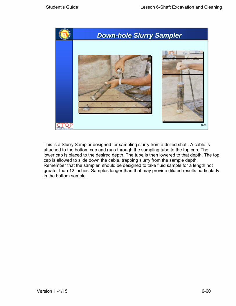
Down-hole Slurry Sampler
This is a Slurry Sampler designed for sampling slurry from a drilled shaft. A cable is attached to the bottom cap and runs through the sampling tube to the top cap. The lower cap is placed to the desired depth. The tube is then lowered to that depth. The top cap is allowed to slide down the cable, trapping slurry from the sample depth. Remember that the sampler should be designed to take fluid sample for a length not greater than 12 inches. Samples longer than that may provide diluted results particularly in the bottom sample.

Student’s Guide Lesson 6-Shaft Excavation and Cleaning
Version 1 -1/15 6-61
6-61
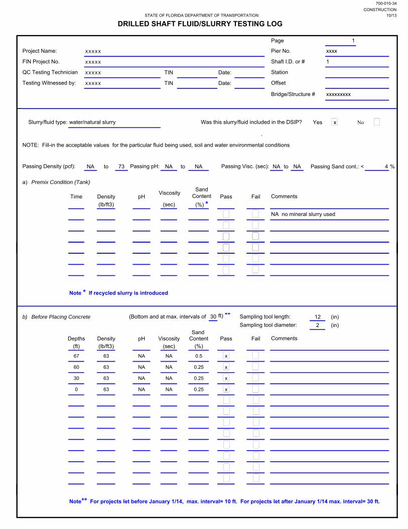
Drilled Shaft Fluid/Slurry Testing LogThis could be filled in advance
These data could be filled in advance
Enter here results for pre-mix condition
Enter measurements
Enter depths of samples
There is a form to be filled by the technician performing the slurry tests. Testing is performed at two instances: prior to introduce to the shaft (premix) and just prior to place concrete. This form is used to document both cases. Fill in every blank on the form. If it does not apply, put an “N/A” or a long dash. Use pencil -- but never erase. If you need to change something, strike a single line through the item and insert the correct information above it. If there is insufficient room to make a note, footnote the item and go to the bottom of the page, or use a separate page.
Student’s Guide Lesson 6-Shaft Excavation and Cleaning
Version 1 -1/15 6-62
6-62
Learning Outcome
How many sets of tests are to be performed within the first 8 hours of mineral slurry use?
Slurry samples are to be obtained at what intervals up the slurry column for testing?

Student’s Guide Lesson 6-Shaft Excavation and Cleaning
Version 1 -1/15 6-63
6-63
Learning Outcome
Which slurry tests are not required if neither mineral nor polymer slurry is being used?
True or FalseTesting of the slurry prior to introduction into the shaftexcavation is not required for drilled shafts to supportmast arms, cantilever signs, overhead truss signs, highmast light poles or other miscellaneous structures.
Student’s Guide Lesson 6-Shaft Excavation and Cleaning
Version 1 -1/15 6-64
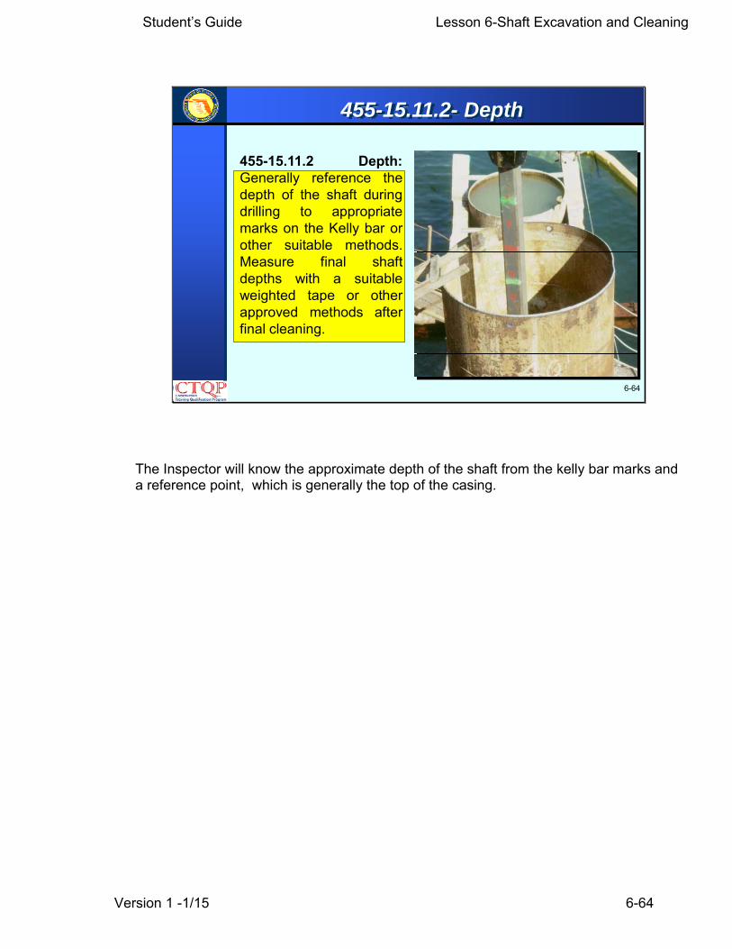
455-15.11.2 Depth:Generally reference thedepth of the shaft duringdrilling to appropriatemarks on the Kelly bar orother suitable methods.Measure final shaftdepths with a suitableweighted tape or otherapproved methods afterfinal cleaning.
6-64
455-15.11.2- Depth
The Inspector will know the approximate depth of the shaft from the kelly bar marks and a reference point, which is generally the top of the casing.
Student’s Guide Lesson 6-Shaft Excavation and Cleaning
Version 1 -1/15 6-65
6-65
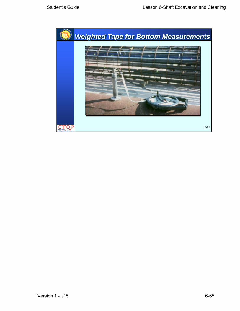
Weighted Tape for Bottom Measurements

Student’s Guide Lesson 6-Shaft Excavation and Cleaning
Version 1 -1/15 6-66
6-66
Shaft Inspection
• Generally determined andverified by lowering a weightedtape down to the bottom of theshaft after cleaning, or
• Contractor’s marks on the kelly.
• Typically measured and recordedto the nearest 0.01 foot from thesupplied reference.
Check specifications for degreeof accuracy,
Student’s Guide Lesson 6-Shaft Excavation and Cleaning
Version 1 -1/15 6-67
6-67
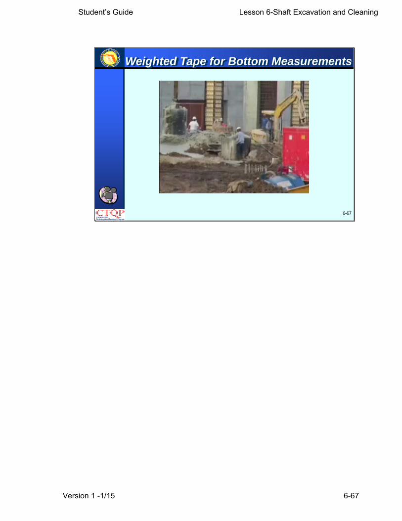
Weighted Tape for Bottom Measurements

Student’s Guide Lesson 6-Shaft Excavation and Cleaning
Version 1 -1/15 6-68
6-68
Bottom Sounding Device
Pictured here at the left side is a shaft sounding device called by the manufacturer as DID, an acronym for Ding Inspection Device. This device measures the thickness of sediments at local points using a strain gage. The measurements appear digitally in an electronic transducer. At the right side a technician is taking the sediment thickness readings with this device. The Department is currently testing this device and considering its use statewide in the near future.

Student’s Guide Lesson 6-Shaft Excavation and Cleaning
Version 1 -1/15 6-69
6-69
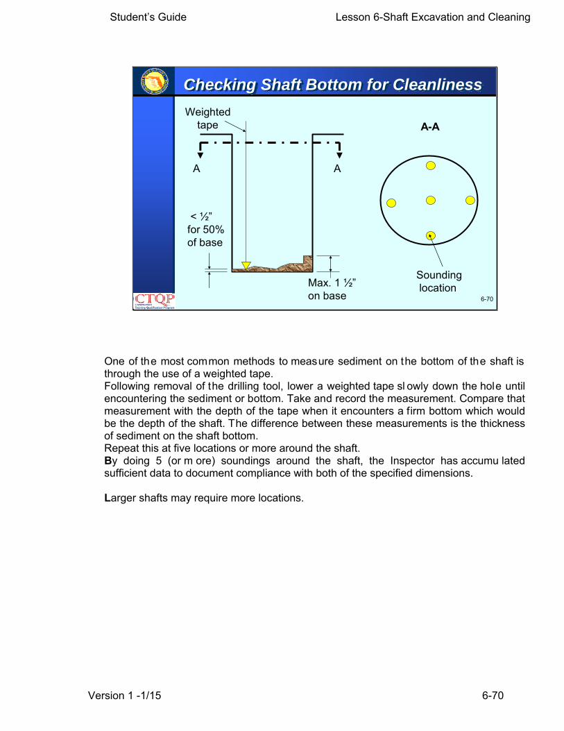
455-15.11.4 Shaft Cleanliness Requirements: Adjustcleaning operations so a minimum of 50% of the bottom ofeach shaft will have less than 1/2 inch of sediment at thetime of placement of the concrete. Ensure the maximumdepth of sedimentary deposits or any other debris at anyplace on the bottom of the shaft excavation does notexceed 1 1/2 inches. The Engineer will determine shaftcleanliness by visual inspection for dry shafts, using diversor an inspection device or other methods the Engineerdeems appropriate for wet shafts.
When using slurry, meet the requirements of 455-15.8 atthe time of concrete placement.
455-15.11.4- Shaft Cleanliness Reqrmt.
Student’s Guide Lesson 6-Shaft Excavation and Cleaning
Version 1 -1/15 6-70
6-70
Max. 1 ½”on base
< ½”for 50%of base
A A
A-A
Soundinglocation
Weightedtape
Checking Shaft Bottom for Cleanliness
One of the most common methods to measure sediment on the bottom of the shaft is through the use of a weighted tape. Following removal of the drilling tool, lower a weighted tape sl owly down the hole until encountering the sediment or bottom. Take and record the measurement. Compare that measurement with the depth of the tape when it encounters a firm bottom which would be the depth of the shaft. The difference between these measurements is the thickness of sediment on the shaft bottom. Repeat this at five locations or more around the shaft. By doing 5 (or m ore) soundings around the shaft, the Inspector has accumu lated sufficient data to document compliance with both of the specified dimensions. Larger shafts may require more locations.

Student’s Guide Lesson 6-Shaft Excavation and Cleaning
Version 1 -1/15 6-71
6-71
455-15.11.4.1 Exceptions for Shafts for MiscellaneousStructures: Ensure the depth of sedimentary deposits orother debris does not exceed 1 inch over the bottom of theshaft when installing drilled shafts to support mast arms,cantilever signs, overhead truss signs, high mast light polesor other miscellaneous structures.
455-15.11.4.1- Exceptions…Misc. Shafts
Student’s Guide Lesson 6-Shaft Excavation and Cleaning
Version 1 -1/15 6-72
6-72
455-15.11.5 Time of Excavation: Any unclassifiedexcavation work lasting more than 36 hours (measuredfrom the beginning of excavation for all methods exceptthe Permanent Casing Method, which begins at the timeexcavation begins below the casing) before placement ofthe concrete requires overreaming the sidewalls to thedepth of softening or removing excessive slurry cakebuildup. Ensure that the minimum depth of overreamingthe shaft sidewall is 1/2 inch and the maximum depth is 3inches….
455-15.11.5- Time of Excavation
Student’s Guide Lesson 6-Shaft Excavation and Cleaning
Version 1 -1/15 6-73
6-73
455-15.11.5- Time of Excavation
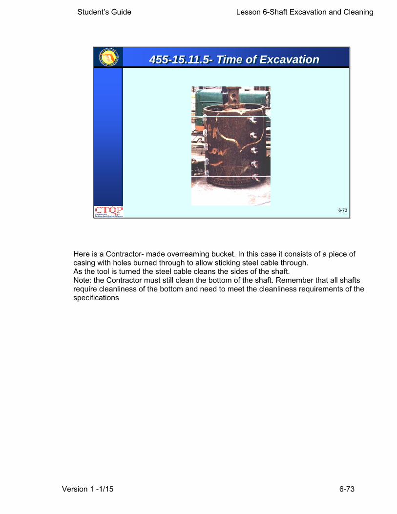
Here is a Contractor- made overreaming bucket. In this case it consists of a piece of casing with holes burned through to allow sticking steel cable through. As the tool is turned the steel cable cleans the sides of the shaft. Note: the Contractor must still clean the bottom of the shaft. Remember that all shafts require cleanliness of the bottom and need to meet the cleanliness requirements of the specifications

Student’s Guide Lesson 6-Shaft Excavation and Cleaning
Version 1 -1/15 6-74
6-74
455-15.11.5 Time of Excavation: Continued
…. Provide any overreaming required at no expense tothe Department when exceeding the 36-hour limitunless the time limit is exceeded solely to accomplishexcavating deeper than the elevation shown in theplans as ordered by the Engineer. The Department willpay the Contractor for authorized overreaming resultingfrom softening or excessive filtercake buildup which isindicated by sidewall samples or other test methodsemployed by the Engineer during the initial 36-hourtime period. ….
455-15.11.5- Time of Excavation

Student’s Guide Lesson 6-Shaft Excavation and Cleaning
Version 1 -1/15 6-75
6-75
455-15.11.5 Time of Excavation: Continued
...The Department will pay the Contractor for authorizedoverreaming when excavating deeper than the elevation shown in the plans as ordered by the Engineer exceeds the36 hour limit.
When using mineral slurry, adjust excavation operations sothat the maximum time that slurry is in contact with the bottom5 feet of the shaft (from time of drilling to concreting) does notexceed 12 hours. If exceeding the 12-hour time limit,overream the bottom 5 feet of shaft at no additional expenseto the Department prior to performing other operations in theshaft.
455-15.11.5- Time of Excavation

Student’s Guide Lesson 6-Shaft Excavation and Cleaning
Version 1 -1/15 6-76
6-76
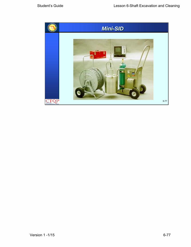
Shaft Inspection Devices (SID)
This photograph shows a mini-SIDs which are currently used in our projects. These are much smaller and easier to mobilize and use than the previous large FDOT device. In addition the camera has a better resolution.
Student’s Guide Lesson 6-Shaft Excavation and Cleaning
Version 1 -1/15 6-77
6-77
Mini-SID
Student’s Guide Lesson 6-Shaft Excavation and Cleaning
Version 1 -1/15 6-78
6-78
455-15.11.3 Shaft Inspection Device (SID):When shown in the plans, furnish all power andequipment necessary for the Engineer to inspectthe bottom conditions of a drilled shaft excavationand the measure the thickness of bottom sedimentor any other debris using a SID. Provide a meansto position and lower the SID into the shaftexcavation to enable the bell housing to restvertically on the bottom of the excavation. Includeall cost related to the inspection device in the costof drilled shaft items.
455-15.11.3- Shaft Inspection Device

Student’s Guide Lesson 6-Shaft Excavation and Cleaning
Version 1 -1/15 6-79
6-79
Learning Outcome
Question:
What if Contractor wants to extend shaft due to debris in bottom at planned tip elevation? Is cleaning still required?
(Ex: Shaft is to be 30 ft. Because there is 2 feet of debris, Contractor wants to drill down to 32 ft.)
Answer:
Student’s Guide Lesson 6-Shaft Excavation and Cleaning
Version 1 -1/15 6-80
6-80
• Folded-in debris- insufficient cleaning of the shaft,excessive cuttings suspended in slurry.
• Soft shaft bottom- incomplete bottom cleaning,side sloughing or sedimentation of cuttingsfrom slurry column.
•Reduced concrete section at the bottom of shaft-bullet shaped tip.
Typical Problem
Student’s Guide Lesson 6-Shaft Excavation and Cleaning
Version 1 -1/15 6-81
6-81
The maximum depth of sediment or debris permittedanywhere on the bottom of a bridge foundation shaft is ___?
Describe a common non-intrusive method ofdetermining shaft cleanliness.
Learning Outcome

Student’s Guide Lesson 6-Shaft Excavation and Cleaning
Version 1 -1/15 6-82
6-82
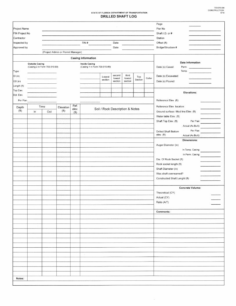
Drilled Shaft LogForm 700-010-84
The Drilled Shaft Log form, Form number 700-010-84 is used to record the events observed during the excavation process. The log consists of two pages. They are available in pdf and excel formats. In the pdf formats the inspector needs to compute the data of the field highlighted in yellow. In the excel format these fields are compute automatically.

Student’s Guide Lesson 6-Shaft Excavation and Cleaning
Version 1 -1/15 6-83
6-83
Drilled Shaft LogForm 700-010-84
Page 1 Page 2
The form contains two pages. These can be accessed in the spreadsheet by clicking the tabs at the bottom.

Student’s Guide Lesson 6-Shaft Excavation and Cleaning
Version 1 -1/15 6-84
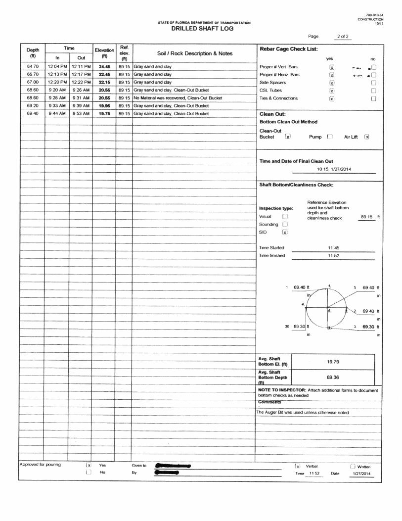
6-84
Drilled Shaft Log1
23
4
5
6
7
8
9
10
We will go to the page 1 first. For our explanation we will divide this page in sections 1 through 10 as shown in the slide

Student’s Guide Lesson 6-Shaft Excavation and Cleaning
Version 1 -1/15 6-85
1
6-85
Drilled Shaft Log
Section 1 consists of the heading with the following basic information:
Project name, Financial project number, Contractor’s name, Inspector’s name, dates, pier number, shaft n umber, stations and offsets and t he bridge or structure number. This information may be filled before drilling starts. Be sure to print your name & the start date of drilling or casing installation.
The Project Administrator or permit manager will sign approval line.

Student’s Guide Lesson 6-Shaft Excavation and Cleaning
Version 1 -1/15 6-86
6-86
Drilled Shaft Log-Page 1Section 2
We will use this slide now to illustrate the section 2 of the form, in which detailed casing information is input. The form allows the input of up to two casings (one outside and one inside). The inside casing may be segmental. The form allows the use of up to 5 segmental sections in the interior casing. The figure at the right side illustrates the casing sections for the input of this part of the form. When using the excel spreadsheet, the yellow fields are formulas and you cannot enter anything on them. Type could be either permanent or temporary. ID, OD are the inside and outside diameters of the casings For the outside casing you input the total length of the casing used. For the i nterior segmental casing you enter the i ndividual segment lengths. The spreadsheet will compute the total length of the segments of the interior casing, and the bottom elevation of both casings. If there is no segments but only one section just enter one section under the top section column. Do not enter it under the collar column as it produces redundant information. Even though the information shown is correct it may be confusing for a reader.

Student’s Guide Lesson 6-Shaft Excavation and Cleaning
Version 1 -1/15 6-87
6-87
Drilled Shaft Log-Page 1
3
4
5
6
This is the right part of page 1 of the form. We will cover now the different sections of this area. Section 3: Enter Da tes of casing i nstallation, dates of e xcavation and the date of pouring. Section 4: Enter in itial reference elevations. Indicate ground surface elevation, water table and the shaft top elevations, both per plans and the as built elevation. The drilled shaft bottom elevation is deter mined after the aver age shaft bottom elevation is calculated in page 2. We will look into page 2 in a moment. Section 5: Enter auger diameter used in inches. Enter rock socket diameter, rock socket length achieved in the shaft, and actual shaft diameters. Indicate whether the shaft was overreamed. The constructed shaft length is calculated from the actual shaf t top elevation and the drilled shaft bottom elevation input in section 4. Section 6 Enter the computed theoretical volume and actual volume of concrete placed and the ratio Actual over theoretical volumes A over T. This will be input after concrete is completed.
Student’s Guide Lesson 6-Shaft Excavation and Cleaning
Version 1 -1/15 6-88
6-88
Drilled Shaft Log-Page 1
7
8
9
10
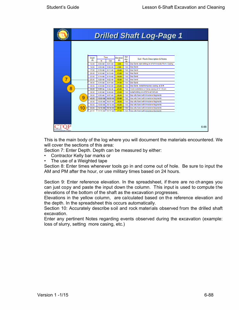
This is the main body of the log where you will document the materials encountered. We will cover the sections of this area: Section 7: Enter Depth. Depth can be measured by either: • Contractor Kelly bar marks or • The use of a Weighted tape Section 8: Enter times whenever tools go in and come out of hole. Be sure to input the AM and PM after the hour, or use military times based on 24 hours. Section 9: Enter reference elevation. In the spreadsheet, if there are no changes you can just copy and paste the input down the column. This input is used to compute the elevations of the bottom of the shaft as the excavation progresses. Elevations in the yellow column, are calculated based on the reference elevation and the depth. In the spreadsheet this occurs automatically. Section 10: Accurately describe soil and rock materials observed from the drilled shaft excavation. Enter any pertinent Notes regarding events observed during the excavation (example: loss of slurry, setting more casing, etc.)
Student’s Guide Lesson 6-Shaft Excavation and Cleaning
Version 1 -1/15 6-89
6-89
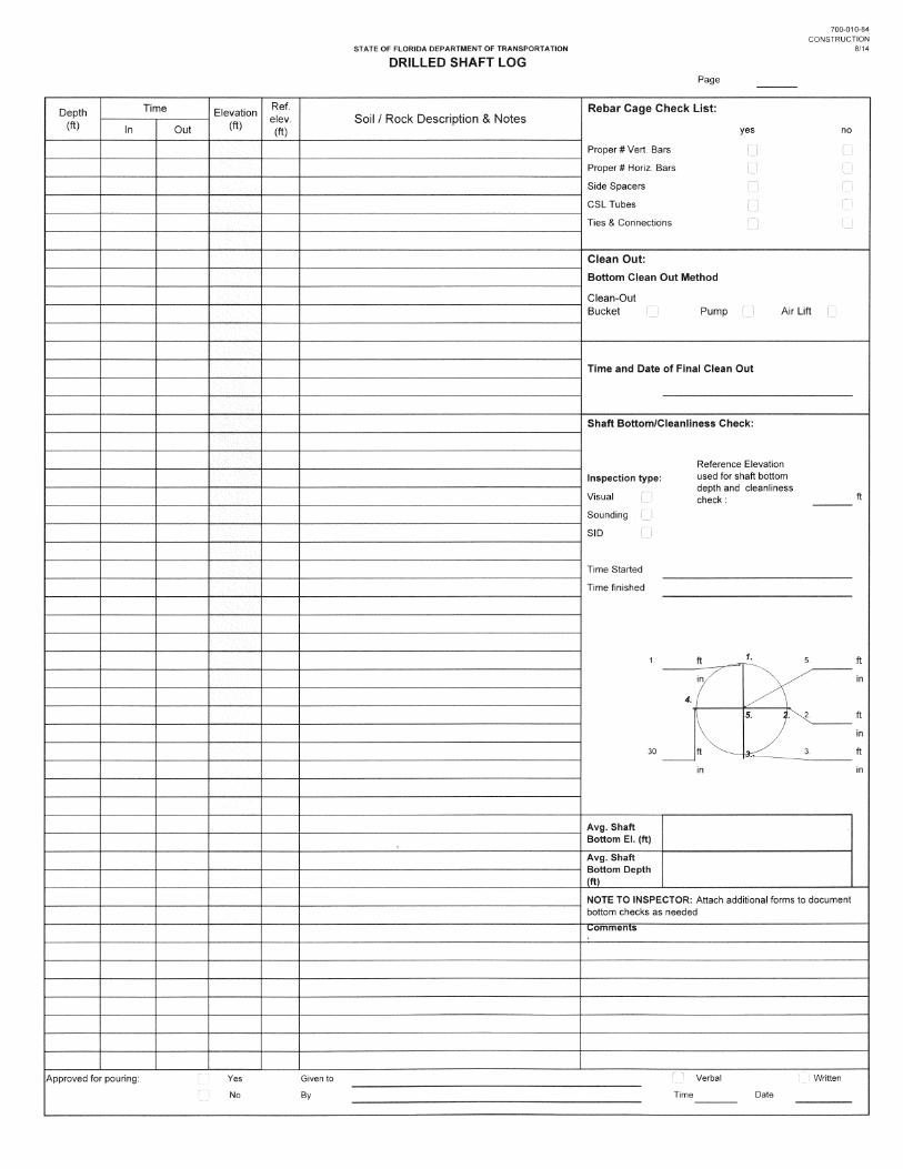
Drilled Shaft Log -Page 2
11
1213
14
15
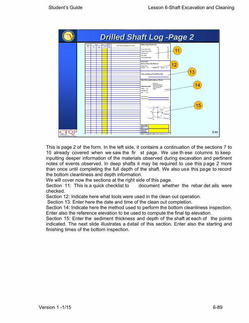
This is page 2 of the form. In the left side, it contains a continuation of the sections 7 to 10 already covered when we saw the fir st page. We use th ese columns to keep inputting deeper information of the materials observed during excavation and pertinent notes of events observed. In deep shafts it may be required to use this page 2 more than once until completing the full depth of the shaft. We also use this page to record the bottom cleanliness and depth information. We will cover now the sections at the right side of this page. Section 11: This is a quick checklist to document whether the rebar det ails were checked. Section 12: Indicate here what tools were used in the clean out operation. Section 13: Enter here the date and time of the clean out completion. Section 14: Indicate here the method used to perform the bottom cleanliness inspection. Enter also the reference elevation to be used to compute the final tip elevation. Section 15: Enter the sediment thickness and depth of the shaft at each of the points indicated. The next slide illustrates a detail of this section. Enter also the starting and finishing times of the bottom inspection.
Student’s Guide Lesson 6-Shaft Excavation and Cleaning
Version 1 -1/15 6-90
6-90
Drilled Shaft Log -Page 2
Depth
Sediment
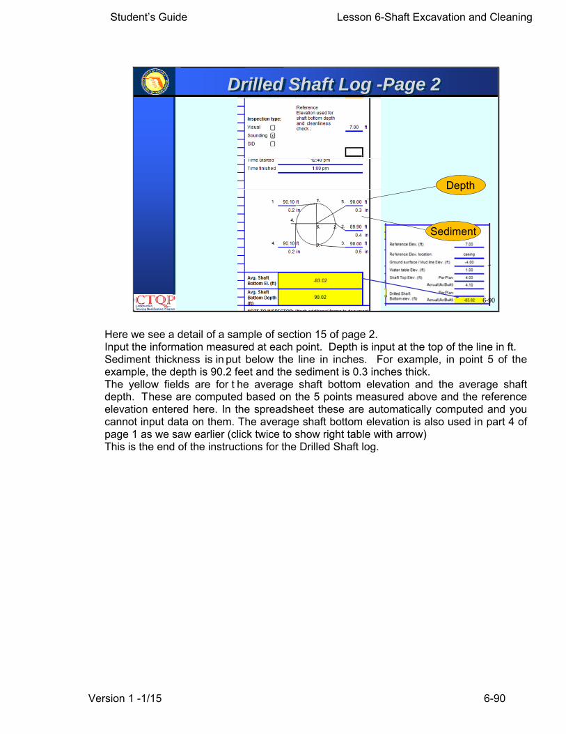
Here we see a detail of a sample of section 15 of page 2. Input the information measured at each point. Depth is input at the top of the line in ft. Sediment thickness is in put below the line in inches. For example, in point 5 of the example, the depth is 90.2 feet and the sediment is 0.3 inches thick. The yellow fields are for t he average shaft bottom elevation and the average shaft depth. These are computed based on the 5 points measured above and the reference elevation entered here. In the spreadsheet these are automatically computed and you cannot input data on them. The average shaft bottom elevation is also used in part 4 of page 1 as we saw earlier (click twice to show right table with arrow) This is the end of the instructions for the Drilled Shaft log.
Student’s Guide Lesson 6-Shaft Excavation and Cleaning
Version 1 -1/15 6-91
6-91
Shaft Inspection Device Log
% Area <1/2” sediments
Max. Sediment in inches
Average of % Area <1/2” sediments
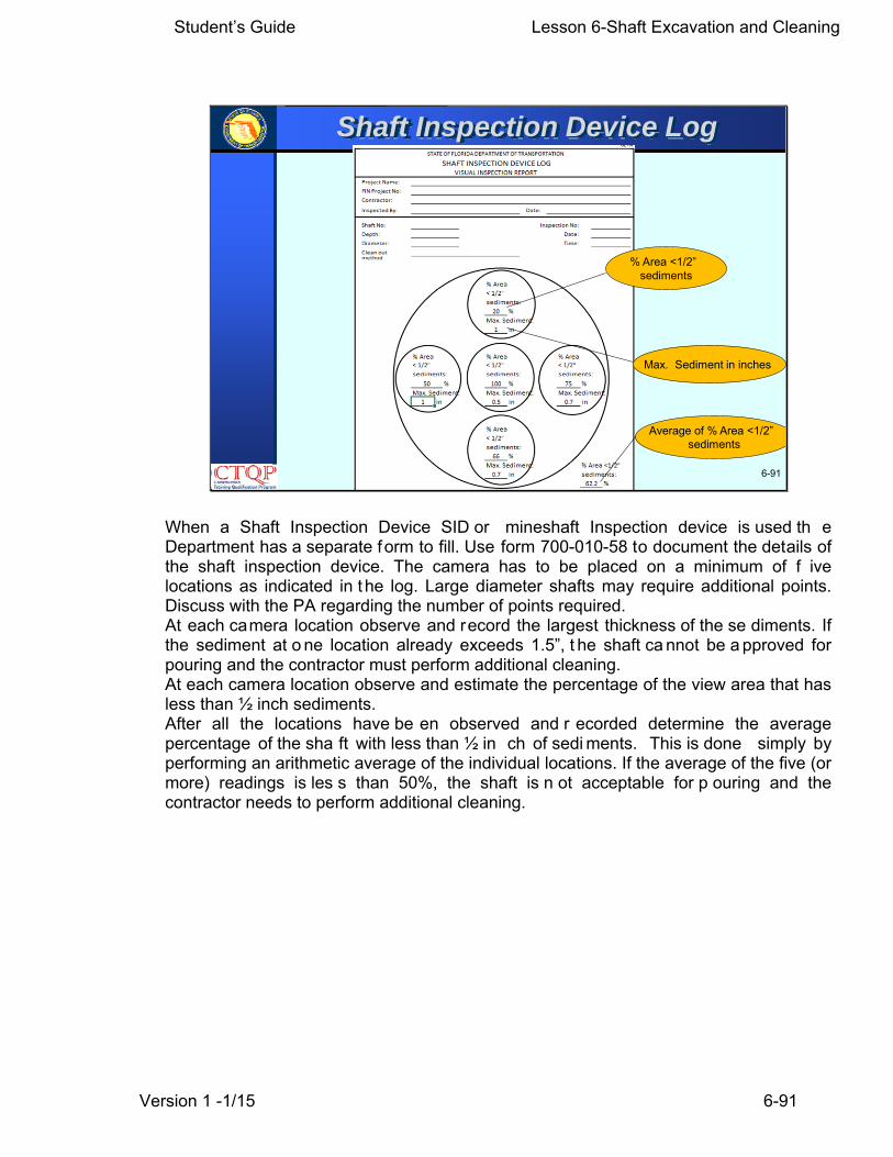
When a Shaft Inspection Device SID or mineshaft Inspection device is used th e Department has a separate form to fill. Use form 700-010-58 to document the details of the shaft inspection device. The camera has to be placed on a minimum of f ive locations as indicated in t he log. Large diameter shafts may require additional points. Discuss with the PA regarding the number of points required. At each camera location observe and record the largest thickness of the se diments. If the sediment at o ne location already exceeds 1.5”, t he shaft ca nnot be a pproved for pouring and the contractor must perform additional cleaning. At each camera location observe and estimate the percentage of the view area that has less than ½ inch sediments. After all the locations have be en observed and r ecorded determine the average percentage of the sha ft with less than ½ in ch of sedi ments. This is done simply by performing an arithmetic average of the individual locations. If the average of the five (or more) readings is les s than 50%, the shaft is n ot acceptable for p ouring and the contractor needs to perform additional cleaning.
Student’s Guide Lesson 6-Shaft Excavation and Cleaning
Version 1 -1/15 6-92
6-92
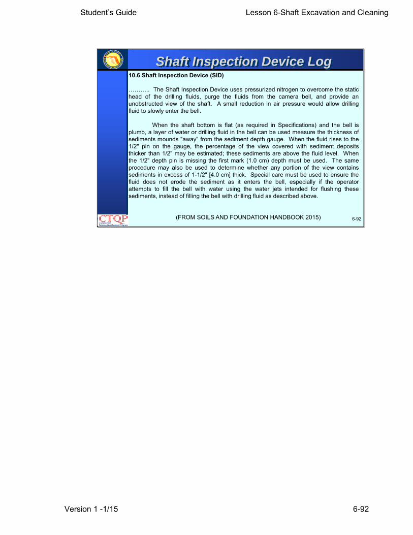
Shaft Inspection Device Log10.6 Shaft Inspection Device (SID)
……….. The Shaft Inspection Device uses pressurized nitrogen to overcome the statichead of the drilling fluids, purge the fluids from the camera bell, and provide anunobstructed view of the shaft. A small reduction in air pressure would allow drillingfluid to slowly enter the bell.
When the shaft bottom is flat (as required in Specifications) and the bell isplumb, a layer of water or drilling fluid in the bell can be used measure the thickness ofsediments mounds "away" from the sediment depth gauge. When the fluid rises to the1/2" pin on the gauge, the percentage of the view covered with sediment depositsthicker than 1/2" may be estimated; these sediments are above the fluid level. Whenthe 1/2" depth pin is missing the first mark (1.0 cm) depth must be used. The sameprocedure may also be used to determine whether any portion of the view containssediments in excess of 1-1/2" [4.0 cm] thick. Special care must be used to ensure thefluid does not erode the sediment as it enters the bell, especially if the operatorattempts to fill the bell with water using the water jets intended for flushing thesesediments, instead of filling the bell with drilling fluid as described above.
(FROM SOILS AND FOUNDATION HANDBOOK 2015)

Student’s Guide Lesson 6-Shaft Excavation and Cleaning
Version 1 -1/15 6-93
6-93
Learning Outcomes
• Perform inspection of drilled shaft excavations for compliance to plans, tolerances and cleanliness.
• Perform visual field verification of soil/rock material for comparison to supplied soil boring data/logs.
• Sample and test slurry and fluid in the excavation.
• Calculate Elevations & Extra Shaft Lengths.
• Identify the applicable 455 Specifications
Student’s Guide Lesson 6-Shaft Excavation and Cleaning
Version 1 -1/15 6-94
6-94
ANY QUESTIONS ?
Questions?


Project Name:FIN Project No:Contractor:
Inspected By: Date:
Shaft No: Inspection No:Depth: Date:Diameter: Time:Clean out method
% Area< 1/2"sediments
%Max. Sediment:
in
% Area % Area % Area< 1/2" < 1/2" < 1/2"sediments: sediments: sediments:
% % %Max. Sediment: Max. Sediment: Max. Sediment:
in in in
% Area< 1/2"sediments:
%Max. Sediment: % Area <1/2"
in sediments:%
Comments
x Given topouring By
Time
STATE OF FLORIDA DEPARTMENT OF TRANSPORTATION
SHAFT INSPECTION DEVICE LOGVISUAL INSPECTION REPORT
100
33 33 100
100
0.5
1 1.25
xxxxxx xx/xx/xx
xx:xx
Approval for Yes
No Date
NOTE: Referring to Specification 455-15.11.4
xx/xx/xxxxxxxxxxxxxx
69.36 ft48 "
xx/xx/xxxx:xx
700-010-58CONSTRUCTION
73.2
air lift and clean out bucket
12-14
0.5
0.5
More than 50% has less than 1/2" sediments. Pass
xxxxxxxxxxxxxxxxxx
xx xx
TIN Date:
TIN Date:
Yes x No
`
NOTE: Fill-in the acceptable values for the particular fluid being used, soil and water environmental conditions
NA to 73 NA to NA NA to NA Passing Sand cont.: < 4 %
a) Premix Condition (Tank)
Time Density pH Pass Fail(lb/ft3) (sec)
Shaft I.D. or #
Station
Offset
Bridge/Structure #
1
xxxx
1
xxxxxxxxx
Project Name:
FIN Project No.
QC Testing Technician
Testing Witnessed by:
700-010-34CONSTRUCTION
10/13
DRILLED SHAFT FLUID/SLURRY TESTING LOG
xxxxx
xxxxx
Page
Pier No.
Passing pH: Passing Visc. (sec):
xxxxx
xxxxx
STATE OF FLORIDA DEPARTMENT OF TRANSPORTATION
water/natural slurry
Passing Density (pcf):
Viscosity
Was this slurry/fluid included in the DSIP?
NA no mineral slurry used
Slurry/fluid type:
Sand Content
(%) *Comments
b) Before Placing Concrete ft) ** 12 (in)2 (in)
Sand Depths Density pH Viscosity Content Pass Fail
(ft) (lb/ft3) (sec) (%)
67 63 NA NA 0.5 x
60 63 NA NA 0.25 x
30 63 NA NA 0.25 x
0 63 NA NA 0.25 x
Sampling tool length:Sampling tool diameter:
30(Bottom and at max. intervals of
Comments
Note * If recycled slurry is introduced
Note** For projects let before January 1/14, max. interval= 10 ft. For projects let after January 1/14 max. interval= 30 ft.