shadowing effects on routing protocol of multihop ad hoc networks
TRANSCRIPT

8/8/2019 Shadowing Effects on Routing Protocol of Multihop Ad Hoc Networks
http://slidepdf.com/reader/full/shadowing-effects-on-routing-protocol-of-multihop-ad-hoc-networks 1/17
!"#$$
10.5121/ijasuc.2010.1102 12
SHADOWING EFFECTS ON ROUTING
PROTOCOL OF MULTIHOP AD HOC
NETWORKS
Md. Anwar Hossain, Mohammed Tarique and Rumana Islam
Faculty of Engineering, American International [email protected]
A BSTRACT
Two-ray ground reflection model has been widely used as the propagation model to investigate the
performance of an ad hoc network. But two-ray model is too simple to represent a real world network. A
more realistic model namely shadowing propagation model has been used in this investigation. Under shadowing propagation model, a mobile node may receive a packet at a signal level that is below a
required threshold level. This low signal level affects the routing protocol as well as the medium access
control protocol of a network. An analytical model has been presented in this paper to investigate the
shadowing effects on the network performance. The analytical model has been verified via simulation
results. Simulation results show that the performance of a network becomes very poor if shadowing
propagation model is used in compare to the simple two-ray model. Two solutions have also been
proposed in this paper to overcome the effects of shadowing. One solution is a physical layer solution and
the other one is a Medium Access Control (MAC) layer solution. Simulation results show that these two
solutions reduce the shadowing effect and improve network performance.
K EYWORDS
Ad hoc networks, shadowing, link distance, probability, delivery ratio, signal-to-interference-plus-noise
power ration (SINR), MAC layer, and transmission power.
1. INTRODUCTION
Mobile Ad hoc Network (MANET) is a highly appealing means of providing network support to
a group of people without the aid of any infrastructure support. MANET consists of a group of mobile nodes that may not be within the range of each other. Necessary controls and networking
functions are performed by using of a distributed control algorithm. MANET is characterized asa multihop communication network unlike a cellular mobile network where each mobile node is
connected to a nearest base station based on a single hop connection. In MANET, a mobile node
forwards packet for other mobile nodes in addition to transmit its own packet. Dynamictopology is another important characteristic of MANET [1]. Mobile nodes may join or leave anetwork at any time. In order to maintain network connectivity under a dynamic topological
condition an efficient routing protocol is very essential for MANET. Existing routing protocolslike Destination Sequence Distance Vector (DSDV) [2], Dynamic Source Routing (DSR) [3]
and Ad-hoc On-Demand Distance Vector (AODV) [4] consist of two main mechanisms namely
route discovery and route maintenance. A mobile node discovers a route or a set of routes to adestination mobile node by using a route discovery mechanism. On the other hand, a mobile
node detects any network topology change by using the route maintenance mechanism. Whileusing any of these two mechanisms, a routing protocol relies on mobile radio channel. Mobile
radio channel places a fundamental limitation on the performance of a MANET. The

8/8/2019 Shadowing Effects on Routing Protocol of Multihop Ad Hoc Networks
http://slidepdf.com/reader/full/shadowing-effects-on-routing-protocol-of-multihop-ad-hoc-networks 2/17
!"#$$
13
transmission path between a transmitter and a receiver can vary from simple line-of-sight to onethat is severely obstructed by buildings, trees, road signs, mountains, and other objects. Hence
mobile radio channel is extremely random unlike its wired counterpart. Different propagationmodels have been proposed in the literatures to predict the signal attenuation that occurs
between two mobile nodes separated by a distance. The ground reflection model or two-ray
propagation model is widely used in the test bed and also in the simulation model [10-17]. Two-ray propagation model assumes that there is a line-of-sight path and a ground reflected
propagation path between a transmitter and a receiver. This model has been found to bereasonably accurate for predicting the large-scale signal strength over distances of several
kilometers for mobile radio system. This model characterizes signal propagation in an isolatedarea with few reflectors such as rural road or highways. It is not typically a good channel model
for a real world mobile communication system especially when the system is deployed in an
urban area. Because this model does not consider the fact that the surrounding environment of anetwork is always changing. In a real world situation, the surrounding environmental cluster is
always changing. This leads to a signal level that can vary vastly across a given distance. The
short-term variations in the signal strength can be as high as 10-20 dB from the mean value of the signal. Measurements have shown that at any given distance, the path loss at a particular
distance is random and distributed log-normally about a mean value [5]. The log-normal
distribution describes the random shadowing effects which occur over a large number of measurements locations that have the same separation distance. This adverse effect of
shadowing on the routing protocol has been investigated in this paper.
One of the first papers related to connectivity issues in wireless multihop network was [18].The authors studied the percolation of a broadcast in a multihop radio network modeled by a
spatial Poisson process. The effect of station density and transmission radius on the extent of broadcast percolation was examined. The results presented in this paper shows that in
optimizing transmission radius as a function of communication performance measures, the
choice of radius may be bounded from below by the need to maintain a desired network connectivity. Another early paper [19] addressed connectivity issues for mobile nodes that are
randomly distributed according to a uniform probability distribution on a one-dimensional linesegment. More recently another work [20] performed a fundamental study on the connectivity
of uniformly distributed mobile nodes on a circular area. According to [20] mobile nodes should
adjust transmission power to a level that is just enough to maintain connectivity in a network provided a mobile node cooperates with other mobile node to route packet. Further analyticalinvestigations of the connectivity in bounded areas were made in [21- 22]. In [21] the authors
analyzed the critical transmission range for connectivity in wireless ad hoc networks. The
authors first considered the connectivity problem for stationary network and provided an upperand lower bound on the critical transmission range for one dimensional network. The authors
evaluated the relationship between the critical transmission range and the minimum
transmission range that ensured formation of a connected component containing a large fraction(i.e., 90%) of the nodes. The authors then extended this work to a mobility condition where
mobile nodes were allowed to move during a time interval. In [22] the authors considered a d -
dimensional region, with 1=d =3 and they presented an analysis to determine the transmissionrange that ensure the resulting network is connected with a high probability. Based on the
bounds of node density the authors concluded that, as compared to the deterministic case, aprobabilistic solution to this range assignment problem achieves substantial energy savings. A
framework for the calculation of stochastic connectivity properties of wireless multihop network has been presented in [23]. In fact, the connectivity problem has been solved for the general
case of a k-connected network accounting for the robustness against node failures. These issueswere studied for uniformly distributed nodel, Gaussian distributed nodes, and nodes that moveaccording to the commonly used random waypoint mobility model. A large scale network with
low node density has been investigated in [25]. The author studied the connectivity for both
purely ad hoc network and hybrid network. In hybrid network, base stations were placed in a

8/8/2019 Shadowing Effects on Routing Protocol of Multihop Ad Hoc Networks
http://slidepdf.com/reader/full/shadowing-effects-on-routing-protocol-of-multihop-ad-hoc-networks 3/17
!"#$$
14
network. Mobile node communicates with other mobile node through the base stations. Theauthors obtained an analytical expression for the probability of connectivity in one dimensional
network. They showed that bottlenecks are unavoidable in a low density sparse network. Mostof the works mentioned so far assume idealized radio propagation model without considering
fading and shadow effects. One of the earliest papers that considered fading and shadowing is
[26]. The authors claim that many well designed protocols will fail simply because of fadingand shadowing experienced in a realistic wireless environment. The authors have shown that
fading and shadowing can have significant influence on network performance. They studiedthree different systems namely (1) a multichannel CDMA system, (2) a pure CDMA system,
and (3) a contention based system. They also show that the multichannel CDMA systemoutperform the pure CDMA system as well as the contention based system under fading and
shadowing environments. The connectivity of multihop radio networks in a log-normal shadow
fading environment has been investigated in [27]. Assuming the mobile nodes have equaltransmission capabilities and are randomly distributed according to a homogenous Poisson
process, the authors provided a tight lower bound for the minimum node density that is
necessary to obtain an almost surely connected subnetwork on a bounded area of given size. Theauthors also provided an insight into how fading affects the topology of multihop networks.
The connectivity of a network from a layered perspective has been investigated in [28]. The
authors first pointed out how the transmission range affects the end-to-end connectionprobability in a long-normal shadowing model and compared the results to theoretical bound
and measurements in the path loss model. The authors then showed how connectivity issuesbehave in 802.11 and IP based networks if fading effects increases. The authors came up with
an analytical model for the link probability in log-normal shadowing environments as a functionof the number of nodes, network area, transmission range, path loss and shadowing deviation.
A probabilistic analysis of the shadowing effects on the signal level variations has also been
presented in this paper. While investigating the impact of shadowing on the network
performance, the delivery ratio has been considered as a performance metric. The delivery ratiois defined as the ratio between the number of packets received at a destination and the number
of packets that was sent by a source to that destination. Hence the packet delivery ratioindicates how many packets were lost in a network. An analytical model to estimate packet
losses in a given network has been presented in this paper. This analytical model has also been
verified via simulation results. In order to investigate the shadowing effects on a routingprotocol, we selected Dynamic Source Routing (DSR)[3] protocol as the candidate. A brief description of the DSR protocol has been provided in the following section for the completeness
of this work. The effects of shadowing on the DSR protocol have been explained in the section
III. The shadowing has grave effects on a medium access control scheme. Since IEEE 802.11MAC layer protocol has been used in this paper, section IV contains a brief description of IEEE
802.11 MAC layer protocol and section V shows the effects of shadowing on IEEE 802.11
MAC layer protocal. Using a derived probability density function based on the results publishedin [6], the mean value of the link distances has been derived in section VI. The probability that
the received signal level will be greater than a threshold level has also been derived in the same
section. Simulation models and results have been presented in section VII. Two solutions of shadowing problem have been presented in the same section. Finally, we conclude this paper in
the last section.
2. THE DSR PROTOCOL
The DSR [3] protocol consists of two basic mechanisms: (1) route discovery, and (2) routemaintenance. Route discovery is the mechanism by which a source node discovers a route to a
destination. When a source node wants to send a data packet, it first looks into its route cache tofind a route. If a source cannot find a route in its route cache, it initiates a route discovery
mechanism by broadcasting a request packet to its neighbours. When a neighbour of a source

8/8/2019 Shadowing Effects on Routing Protocol of Multihop Ad Hoc Networks
http://slidepdf.com/reader/full/shadowing-effects-on-routing-protocol-of-multihop-ad-hoc-networks 4/17
!"#$$
15
receives a request packet, it first checks whether the request packet is intended for it or not. If aneighbour discovers that it is the destination, it sends a reply back to the source after copying
the accumulated routing information contained in the route request packet into a route replypacket. If a neighbour discovers that it is not the destination of this request packet, it checks for
a route in the route cache for that destination. If this neighbour is neither a destination nor it has
a route in the route cache to that destination, it appends its address in the route request packetand re-broadcasts the route request packet to its neighbours. This process continues until a route
request packet reaches at the destination node. Then the destination node replies all routerequests that it receives. When a source node receives a route reply packet, it starts sending data
packets using the route indicated in the reply packet. If multiple paths are discovered, it choosesa path that is the shortest one.
A typical route discovery mechanism of DSR protocol is illustrated in Figure 1. In this scenario,mobile node ‘1’ is the source and mobile node ‘5’ is the destination. Mobile node ‘1’ does not
have any route in its cache to this destination. Hence it initiates the route discovery mechanismby broadcasting a request packet. When some neighbouring nodes like mobile node ‘2’ and ‘6’
receive the request packet, they put their addresses in the request packet and re-broadcast thatrequest message. Similarly mobile nodes ‘3’,’4’ and ‘7’ also rebroadcast that request packet
Figure1. Route discovery mechanism of DSR protocol
until the destination node ‘5’ receives it. The destination node ‘5’ then replies back to the sourcenode ‘1’ by using a route reply packet. The route reply packet contains the information of the
route that has been just discovered. After receiving the route reply packet, mobile node ‘1’records all the routes in its route cache. In this simple scenario, two routes namely ’1-2-3-4-5’
and ‘1-6-7-5’ are discovered. According to the routing algorithm, mobile node ‘1’ should selectthe shortest path between these two paths. In this case, the shortest path is ‘1-6-7-5’. After
selecting this shortest path, the source node starts sending data packet by using the route ‘1-6-7-5’.
Figure 2. Route maintenance mechanism of DSR protocol
1
2 3 4
56 7
[1]
[12] [123]
[1234]
[1] [16] [167]
route request route reply
1
2 3 4
56 7
Current route Alternate route

8/8/2019 Shadowing Effects on Routing Protocol of Multihop Ad Hoc Networks
http://slidepdf.com/reader/full/shadowing-effects-on-routing-protocol-of-multihop-ad-hoc-networks 5/17
!"#$$
16
Route maintenance is the mechanism by which a node is able to detect any change in thenetwork topology. When a node detects a ’broken’ link, for example, by using missing MAC
layer acknowledgments, it removes the link from its route cache and sends a route error messageto each node that has sent packets over that link. A typical route maintenance mechanism is
shown in Figure 2. Let us assume that the link between mobile node ‘3’ and ‘4’ is ‘broken’ due
to battery exhaustion of mobile node ‘4’. Mobile node ‘3’ detects that the mobile node ‘4’ isunreachable by using a MAC layer mechanism. Mobile node ‘3’ then creates a route error
message and sends it to the source. A route error message contains the information of the faultylink (i.e., 3-4). After receiving the route error message, the source mobile node ‘1’ marks the
route ‘1-2-3-4-5’ as invalid route and tries to find an alternative route from its route cache.Since an alternative route ‘1-6-7-5’ is there in the route cache, the source mobile node should
select that route and start using this new route.
3. EFFECTS OF SHADOWING ON ROUTING PROTOCOL
In the route discovery and route maintenance operation of the DSR protocol, it is assumed that
the link between two nodes is stable and the variation of signal level only depends on the
distance between them. That means a neighbouring node is always ‘reachable’ unless this
neighbour is not out of battery or it has moved out of the reach. But shadowing effect assumesthat the signal level can vary widely for a given distance between two nodes. This increases the
probability that the signal level may go below a certain required level called a ‘threshold’ level.In this case, a receiving mobile node may not successfully receive a packet. Hence the following
problems may arise:
(a) The route request packet may not reach all the neighbours. Hence there is a probabilityof an unsuccessful route discovery. That means the route request packet may not
reach to a destination.
(b) The route discovery mechanism may not be an efficient one. The route discoverymechanism of the DSR protocol aims to discover as many paths as possible. The
reason is that if one path fails, a source can selects an alternative path instantly. Butthis kind of flexibility may be lost under shadowing condition. Since only a few
number of paths are discovered, there is a probability that a source may not find any
other alternative route once a current route fails.(c) Once some routes are discovered and a source mobile node starts sending data packets
using one of the discovered routes, a neighbouring node may not receive that datapacket because of the wide variation of signal. Hence a data packet may be lost
at an intermediate node.(d) The route maintenance operation of the DSR protocol also may not work properly
because there is a probability that a route error message may be lost during its way to a
source mobile node. If a source does not receive the route error message, it cannot
detect a link breakage. The source continues sending data packet using the route thatcontains the broken link. All these data packets will be lost at the broken link.
The shadowing not only affects a routing protocol but also makes problems for a medium accesscontrol scheme. In all the simulation results presented in this paper, IEEE 802.11 has been
chosen as the medium access protocol. A brief description of IEEE 802.11 MAC layer has been
described in the following section.
4. IEEE 802.11 MAC LAYER
Like other IEEE 802.x protocol, the IEEE 802.11 protocol defines the Medium Access Control
(MAC) and physical layers. The IEEE 802.11 MAC layer defines two different access methodsnamely Distribution Coordination Function (DCF) and Point Coordination Function (PCF). We
will now only describe DCF based MAC protocol since PCF based MAC protocol cannot be

8/8/2019 Shadowing Effects on Routing Protocol of Multihop Ad Hoc Networks
http://slidepdf.com/reader/full/shadowing-effects-on-routing-protocol-of-multihop-ad-hoc-networks 6/17
!"#$$
17
used in an ad hoc network. The basic access mechanism of DCF based MAC protocol isbasically a Carrier Sense Multiple Access with Collision Avoidance (CSMA/CA). The main
mechanism of CSMA/CA protocol is as follows: a mobile node senses the medium beforetransmitting its packet. If it finds that the medium is free, it transmits its packet. But if the
medium if busy, a mobile node defers its transmission to a later time which is chosen randomly.
IEEE 802.11 protocol includes both physical carrier sensing and virtual carrier sensing.
Figure 3. Carrier sensing in IEEE 802.11
Physical carrier sensing is used to detect other mobile nodes operating in the same network byanalyzing all detected packets. It also helps to detect activities in the channel via relative signal
strength from other sources. Virtual carrier sensing is performed by sending MPDU duration
information in the header of Request-to-Send (RTS), Clear-to-Send (CTS), and data frames as
shown in Figure 3. In addition to header information, payload and a 32-bits CRC, MPDU also
contains a duration field. The duration field contains information of the time duration that willtake this data or management frame to complete transmission. Other mobile stations in the samearea use this information to adjust their Network Allocation Vector (NAV), which indicates the
amount of time that must elapse until the current transmission session is completed and the
channel can be sampled again for idle status. The channel is marked busy if either the physicalor virtual carrier sensing mechanism indicates the channel is busy. Priority access to thewireless medium is controlled through the use of Inter-Frame Space (IFS) time intervals
between the transmissions of frames. Two IFS intervals are specified in IEEE 802.11 standard(a) Short Inter-frame Space (SIFS) and, (b) DCF Inter-Frame Space (DIFS). The SIFS is the
smallest IFS after a DIFS as shown in Figure 3. When a station senses the medium and finds itis idle, it has to wait for a DIFS period to sense the medium again. If the channel is still idle, themobile station transmits its MPDU. Upon receiving the MPDU, a receiver checks the checksum
to determine whether a packet was received correctly or not. If a packet is received correctly, a
receiver waits for a SIFS time period and sends a positive acknowledgement (ACK) to thetransmitting station to indicate that the transmission was successful. If an acknowledgement isnot received within a given time period, another attempt is made to send a packet again. The
number of times a source attempts to send a packet is determined by an important parameternamed ‘Long Retry Limit’. When the number of attempts exceeds this limit, a source discards a
packet permanently. Since each mobile node has a limited buffer to store packet, this ‘Long
Retry Limit’ parameter helps a mobile node to operate with a limited packet buffer size. Inorder to reduce collision and save channel bandwidth, Request-to-Send (RTS) and Clear-to-Send (CTS) are also used in IEEE 802.11 layer. RTS and CTS control frames are used by a
Source
Destination
Other nodes
Data
SIFS
ACK
DIFS
CW
NAV
Defer AccessBack-off after defer
Slot time

8/8/2019 Shadowing Effects on Routing Protocol of Multihop Ad Hoc Networks
http://slidepdf.com/reader/full/shadowing-effects-on-routing-protocol-of-multihop-ad-hoc-networks 7/17
!"#$$
18
station to reserve channel bandwidth prior to the transmission of MPDU. The timing diagram of RTS and CTS packets are shown in Figure 4. The RTS control frame is first transmitted by a
source mobile. All other stations in a given area read the duration field and set their NAVsaccordingly. The destination station responds to the RTS packet with a CTS packet after an
SIFS idle period has elapsed. Mobile stations hearing the CTS packet look at the duration field
and again update their NAV. Upon successful reception of the CTS, the source station isvirtually assured that the medium is stable and reserved for successful transmission of the
MPDU. In this way, the mobile stations update their NAVs based on the information contents of RTS and CTS packets, which helps to combat ‘hidden terminal’ problem. The collision
avoidance portion of CSMA/CA is performed through a random back-off procedure. If a mobilestation with a frame to transmit senses the channel and finds the medium is busy, then the
mobile node waits for a DIFS period. At the end of the DIFS period, the mobile station
computes a random period of time called back-off period. In IEEE 802.11, time is slotted intime periods that corresponds to a time unit called slot time. The random back-off time is an
integer value that corresponds to a number of time slots. Initially, the mobile station computes a
back-off time in the range of 0-31. This period is called the contention window as shown in
Figure 4. Transmission of MPDU with RTS and CTS
figure 4. After this contention period, a mobile node again senses the medium. If it finds themedium busy again, it goes for longer contention period. On the other hand, if it finds the
medium free, it waits for DIFS period to make sure no other mobile node is transmitting. If noother mobile node transmits during that period, a mobile node starts transmitting its own packet.
5. EFFECTS OF SHADOWING ON MAC LAYER
The CSMA/CA based multi-access technique assumes that the medium is an intermittent
synchronous multi-access bit pipe on which idle periods can be distinguished from packettransmission periods. If nodes can detect idle periods quickly, it is reasonable to terminate idle
periods quickly and to allow nodes to initiate packet transmission after such idle detections.This is the philosophy of a CSMA/CA based multiple access technique. Shadowing effects mayput hurdle on the normal operation of IEEE 802.11 MAC layer operation in the following ways:
(a) as mentioned in the earlier section that IEEE 802.11 carrier sensing is performed at both the
air interface, which is referred to as physical carrier sensing and at the MAC sub-layer referredto as virtual carrier sensing. Physical sensing may not work properly due to shadowing because
signal level may go below a threshold level so that it cannot be detected. Hence both physicalcarrier sensing and virtual carrier sensing may not work properly, (b) a source station performs
virtual carrier sensing by sending MPDU duration information in the header of RTS, CTS and
data packets. Stations in a given area use this information in the duration field to adjust their
Network Allocation Vector (NAV). The NAV indicates the amount of time that must elapse
Source
Destination
Other node
DIFS
SIFS
RTS
CTS
SIF
DATA
SIF
ACK
NAV(RTS)NAV(CTS)
NAV(DATA)
DISF
Defer access
Back-off started

8/8/2019 Shadowing Effects on Routing Protocol of Multihop Ad Hoc Networks
http://slidepdf.com/reader/full/shadowing-effects-on-routing-protocol-of-multihop-ad-hoc-networks 8/17
!"#$$
19
until the current transmission session is complete and the channel can be sampled again for idlestatus. The stations in a given area may not be able to recover the bit duration information from
the packet because of the poor signal level arisen from the shadowing effects. Hence theadjustment of NAV cannot work properly, (c) The RTS and CTS frame exchanging between a
source station and a destination station may not be successful due to variation of signal level. If
the destination station does not receive RTS packet due to signal variation, it does not reply thatRTS by sending a CTS packet. Since a source station cannot send a data packet unless it
receives a CTS packet from the destination, a source station has to keep the data packet in thebuffer for longer period of time. Similarly, if the CTS packet is not successfully received by a
source station due to signal variation, a source station also delays its transmission. Henceunsuccessful reception of RTS and CTS packets can cause unnecessary delaying of a packet
transmission, (d) according to IEEE 802.11 after receiving a data packet, a source station sends
an acknowledgement. A destination station may not receive a data packet successfully due tovariation of the signal strength. Hence a source station has to resend a data packet several
times. These redundant packets will occupy channel unnecessarily and waste scarce channel
bandwidth. On the other hand, a destination may successfully receive a packet, but theacknowledgement packet sent by that destination may be lost due to shadowing effects. Since a
source node does not receive an ACK packet, it keeps sending the data packet repeatedly.
According to IEEE 802.11 MAC layer, a source has the opportunity to resend a packet for seventimes after that it will assume that the destination is unreachable and it drops the packet. Hence
there will be a large number of packet losses in a network due to unsuccessful reception of anACK.
6. DERIVATION OF EXPRESSION
In a uniform random network scenario, the location of a mobile node is determined according touniform random variables. That means the location of a mobile node is determined by x co-ordinate and y co-ordinate that are two uniform random variables between 0 to A and 0 to B
respectively, where A and B are the length and width of a network. To determine the averagelink distance between a given source-destination pair, we rely on the link distribution model
presented in [6]. It is shown therein that when a number of mobile nodes are uniformly
distributed over a rectangular area the probability density function )( 1 D pd ξ γ = of the link
distances between any two mobile nodes can be expressed as follows:
1
2
2
1 1
2 2 2 21
2 2
( )
[2 4 (1 ) 2 ], 0 1
4 1 2 (2 )
4 sin (1 / ), 11
4 1 4
2 (
d p D
D
γ ξ
ζ ξ ζ ξ ξ ζ π ξ
ζ ξ ξ ζ ξ ξ ζ
ζ ξ ξ ξ ζ
ζ ξ ξ ζ ξ ξ ζ
ξ ζ ξ
− −
−
= =
− + + ≤ <
− − + +
≤ <
− + − −
2 1 1 1 21 ) 4 {sin (1 / ) cos (1 / )}, 1
0, otherwise
ζ ζ ξ ξ ζ ξ ζ ξ ζ − − − −
+ + + − ≤ < +
(1)
,where2
1
D
D=ζ is the shape parameter of a rectangular area, 1 D is the width and 2 D is the
length of the rectangular area, 1 Dγ ξ = is given by2
2
2
10 D D +≤< γ . The mean value of the
link distance is defined by1[ ] ( )d
E p D d ξ ξ ξ ξ = . Figure 5 depicts the variation of the mean
link distance and number of hops between a source and a destination node. It is shown in this

8/8/2019 Shadowing Effects on Routing Protocol of Multihop Ad Hoc Networks
http://slidepdf.com/reader/full/shadowing-effects-on-routing-protocol-of-multihop-ad-hoc-networks 9/17
!"#$$
20
figure that the link distance variation is almost linear with respect to the network area of operation. If the shadowing effect is ignored, the received power level at any mobile node in
0 1 2 3 4 5 6 7 8 9 10
x 105
0
500
1000
1500
Area in Square Metre
M e a n L i n k D i s t a n c e
0 1 2 3 4 5 6 7 8 9 10
x 105
0
2
4
6
8
Area in Square Metre
N u m b e r o f H o p s
dmin=200 m
Figure 5. Mean link distance and number of hops for a rectangular service area
an ad hoc network depends on the link distance between two mobile nodes. Since the mobile
node has limited transmission power, a packet should travel multiple hops from a source to adestination. If the transmission range corresponding to a transmission power is fixed and it is
denoted by R, then the number of hops a packet should travel is given by [ ] E H
R
ξ =
. If we do
not consider the shadowing effects, then the quality of each link should remain constantduring the operation of the network. But this is not a valid assumption under a shadowing
condition. Shadowing causes a wide range variation of the received signal. It increases the
probability that the received signal goes below a threshold level. Hence a packet may not becorrectly received by a receiver. The analytical model presented in this section is based on the
following assumptions: (1) all link distances are uniform within a rectangular service area,
(2) the characteristic of the channel is almost same over the whole rectangular service area (i.e.,the whole network has shadowing effect), (3) the node density (i.e., number of nodes per squaremeter) is kept constant when network size is varied, and (4) once a packet is successfullyreceived, the receiving mobile node re-transmits that packet at the same power level at which
the previous node has transmitted the same packet to itself. Shadowing effect states that at any
given distance d from a transmitter, the path loss ( )PL d at a particular location is random and
distributed log-normally (normal in dB) about the mean distance-dependent value [5].
Therefore, path loss and received power at d meter from the transmitter is modelled as follows:
σ X d
d nd PLdBd PL ++= )log(10)()(
0
0
_
(2)
where )( 0
_
d PL is the average path loss at a reference distance 0d and is given
by ))4 /((log10)( 20
210
_
0 d d PL π λ −= [7], λ is the wave length of the signal, n is the path loss
exponent, σ X is a Gaussian random variable with a mean value of 0 . If this path loss model is
used, the received power )(d Pr at distance d from a transmitter is given by
])log(10)([)(0
0
_
σ X d
d nd PLPdBd P t r ++−= (3)

8/8/2019 Shadowing Effects on Routing Protocol of Multihop Ad Hoc Networks
http://slidepdf.com/reader/full/shadowing-effects-on-routing-protocol-of-multihop-ad-hoc-networks 10/17
!"#$$
21
where t P is the transmission power. The probability density function of the path loss due to
shadowing effects can be expressed as [8]
2
0
0( ) 2
( ( ) 10 log10( ))1
( ) exp( )
22
PL d
d x PL d n
d p x
σ πσ
− −
= − (4)
40 50 60 70 80 90 100 110 120 130 1400
0.02
0.04
0.06
0.08
0.1
0.12
0.14
Path Loss in dBm
P r o b a b i l i t y D e n s i t y F u n c t i o n o f P a t h L o s s
186m80m4m 40m
Figure 6. Comparison results of probability density functions of path loss at 4d = , 40, 80, and
186m
The probability density functions for path loss using Equation (4) is a Gaussian log-normal
distribution. The distance dependent mean values of path losses at 4,40,80, and 186d =
meter far from the receiver is 50, 80, 88, and 100 dBm respectively shown in the Figure 6.
0 20 40 60 80 100 120 140 160 180 2000
20
40
60
80
100
Distance in Metre
0 2 4 6 8 10 12
x 104
0
20
40
60
80
100
Area in Square Metre
% P
r o b a b i l i t y o f R e c e i v e d P o w e r G r e a t e r T h a n T h
r e s h o l d
Figure 7. Probability of received power greater than threshold power level with respect to
distance d and circular area2d π
Based on the analysis presented in [5], the probability that the received signal level will be
greater than the threshold powerthP can be expressed as
8/8/2019 Shadowing Effects on Routing Protocol of Multihop Ad Hoc Networks
http://slidepdf.com/reader/full/shadowing-effects-on-routing-protocol-of-multihop-ad-hoc-networks 11/17
!"#$$
22
0
0
( ( ( ) 10 log( ))1 1
( ( ) ) ( )2 2 2
th t
r r th
d P P PL d n
d P P d P erf
σ
− − +
> = − (5)
where σ is the standard deviation (in dB), thP is the threshold power and ( )erf ⋅ denotes error
function. Figure 7 shows the probability of received power greater than the threshold power thP
is plotted with respect to distance d and circular area2d π considering the shadowing effect in
microcellular environment. The probability of the percentage of the network area where the
received signal is greater than the threshold levelthP , is denoted by ( ( ) )r r thP P d P> is plotted
in Figure 7. Figure 7 shows that if the distance between two nodes is less than 40 meter, theshadowing effect is not very significant. There is almost 100% probability that the received
signal will be above a threshold level. But the probability ))(( thr r Pd PP > decreases
exponentially as the distance between two nodes becomes greater than 40 meter and it becomeseventually 5% when the distance between two nodes is around 165-175 meter. From this
observation, it can be concluded that although the shadowing effect is not significant for a small
network, but the shadowing effect will be more severe for a large network. When the averagelink distance is more than 165 meter, there will be almost 95% packet loss in a network.
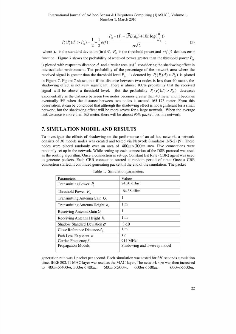
7. SIMULATION MODEL AND RESULTS
To investigate the effects of shadowing on the performance of an ad hoc network, a network consists of 30 mobile nodes was created and tested via Network Simulator (NS-2) [9]. These
nodes were placed randomly over an area of mm 300400 × area. Five connections were
randomly set up in the network. While setting up each connection of the DSR protocol was used
as the routing algorithm. Once a connection is set-up, Constant Bit Rate (CBR) agent was usedto generate packets. Each CBR connection started at random period of time. Once a CBR
connection started, it continued generating packet till the end of the simulation. The packet
Table 1: Simulation parameters
generation rate was 1 packet per second. Each simulation was tested for 250 seconds simulation
time. IEEE 802.11 MAC layer was used as the MAC layer. The network size was then increased
to ,400400 mm × ,400500 mm × ,500500 mm × ,500600 mm × ,600600 mm ×
Parameters Values
Transmitting Powert
P 24.50 dBm
Threshold PowerthP -64.38 dBm
Transmitting Antenna Gain t G 1
Transmitting Antenna Height t h 1 m
Receiving Antenna Gain r G 1
Receiving Antenna Heightr h 1 m
Shadow Standard Deviationσ 3 dB
Close Reference Distance 0d 1 m
Path Loss Exponent n 3.0
Carrier Frequency f 914 MHz
Propagation Models Shadowing and Two-ray model

8/8/2019 Shadowing Effects on Routing Protocol of Multihop Ad Hoc Networks
http://slidepdf.com/reader/full/shadowing-effects-on-routing-protocol-of-multihop-ad-hoc-networks 12/17
!"#$$
23
,600700 mm × and mm 700700 × by keeping the node density constant so that the network
connectivity is not affected. That means there are 40, 50, 62, 75, 90, 105 and 122 mobile nodes
were deployed over the network area when the network sizes were
,400400 mm × ,400500 mm × ,500500 mm × ,500600 mm × ,600600 mm ×
,600700 mm × and mm 700700 × respectively. The total number of data packets generated in
the network at the source mobile nodes and the total number of data packets delivered to thedestination mobile nodes were monitored during each simulation. The delivery ratio is the ratio
defined bysent
recvd
N
N =γ . For a given area, ten different topologies were created and tested by
using different seeds. Ten simulation results were then averaged. The other simulation
parameters are shown in Table I. The transmission range is 250 meter with the giventransmission power level of 24.50 dBm and the threshold power of -64.38 dBm. These are the
default values of these two parameters in Network Simulator (NS-2) [9].
The two-ray model has been used as the propagation model. As mentioned in the previous
section that two-ray model is too simple to represent a real world scenario. The two-ray
reflection model assumes that there are two paths between a source and a destination. One path
is the line-of-sight path and the other one is the reflected path from the ground. The variation of the signal strength follows the following rule [5]
4
22
d
hhGGPP r t
r t t r = (6)
wheret
G andr G are the transmitting antenna gain and receiving antenna gain,
t h and
r h are
0 20 40 60 80 100 120 140 160 180 200-80
-60
-40
-20
0
Distance in Metre R e
c e i v e d P o w e r L e v e l i n d B m
5 6 7 8 9 10 11 12 13
x 105
99.85
99.9
99.95
100
Area in Square Metre
D e l i v e r y R a t i o
Received Power for Two-ray
Threshold Power -64.38dBm
Figure 8. Delivery ratio of simplest two-ray channel model with respect to rectangular area
the transmitting and receiving antenna heights,t
P is the transmitting power andr P is the
receiving power, and d is the distance between the transmitter and the receiver. Based on the
two-ray model the received signal variation is illustrated in the upper graph of Figure 8. The
figure shows that the received power level remains above a threshold power levelth
P unless the
distance between a transmitter and a receiver is 160 meter. After that the received signal levelgoes below a threshold level. Hence there will be packet losses in the network if a network is
large enough to have average link distance greater than 160 meter. Since each mobile node uses

8/8/2019 Shadowing Effects on Routing Protocol of Multihop Ad Hoc Networks
http://slidepdf.com/reader/full/shadowing-effects-on-routing-protocol-of-multihop-ad-hoc-networks 13/17
!"#$$
24
the same power level to transmit all kinds of packets (i.e., route discovery, route maintenanceand data packets), the link up to 160 meter is considered stable in this case. That means once a
route is discovered, the qualities of all links lying along that route do not change over the time.Hence there is almost no packet loss. The lower graph of Figure 8 also depicts the simulation
results. It shows that the delivery ratio for two-ray model is almost 100%. That means anegligible number of packets has been lost. This figure shows that the delivery ratio is 100%
under different network size. Because the average link distance is those simulated networks isless than 160 meter. The above mentioned simulations were repeated with shadowing
propagation model by keeping other parameters mentioned in Table I same. The simulation
results with that of the probabilistic analytic model are shown in the Figure 9. It is depicted that
0 2 4 6 8 10 12 14
x 105
0
10
20
30
40
50
60
70
80
90
100
110
Area in Square Metre
% P r o b a b i l i t y / D e l i v e r y R a t i o
Theoritical Value of Probability for Shadowing Model
Simulated Value of Delivery Ratio for Shadowing Model
Simulated Value of Delivery Ration for Two-ray Model
Figure 9. Comparison of simulated delivery ratios of two-ray channel model and shadowingmodel and theoretical probabilistic analytic result of shadowing model
the delivery ratio is almost 100% when network area is less than or equal to5
1.6 10× square
meter. After that the delivery ratio decreases exponentially as the network gets larger. The
delivery ratio decreases exponentially to almost 15% when the network size was mm 700700 × .
This exponential drop in the delivery ratio complies with the theoretical model derived insection VI where it was shown that the probability of the received power is greater than the
threshold power level. In order to successfully receive a packet, the received signal level should
be greater than the threshold value defined by the parameter (i.e.thP ), which is listed in Table 1.
The decision of successfully received a packet is determined by the probability defined
as ))((thr r
Pd PP > since successfully received packets solely depend on the received power that
is a random variable for shadowing model. This probability is directly proportional to thedelivery ratio within the same rectangular area where link distance is almost linearly increasedwith the rectangular area, i.e.,
Delivery ratio = ( ( ) )r r thk P P d P> (7)
where k is a scaling factor constant. Both the theoretical and simulation results of shadowing
model are shown in Figure 9. In addition to these results, simulation result of two-ray model isalso plotted in the same graph to show the difference between the network performance under
two-ray model and shadowing model. Two methods that can reduce the shadowing effects

8/8/2019 Shadowing Effects on Routing Protocol of Multihop Ad Hoc Networks
http://slidepdf.com/reader/full/shadowing-effects-on-routing-protocol-of-multihop-ad-hoc-networks 14/17
!"#$$
25
suggested in this paper are: (1) by increasing the transmission power, and (2) by increasing theretry-limit of MAC layer protocol. The first solution is a physical layer solution. This solution
of reducing shadowing effects is to increase the transmission power level.
As shown in Equation (3) that the received signal level at a given distance will increase if the
transmission powert
P is increased. To investigate how a higher transmission power can reduce
the shadowing effect the previous simulations have been repeated here. But the transmission
power is increased to 0.58432 watts (or 27.67 dBm). This transmission range of a mobile forthis new transmission power is 300 meter (if two-ray model is used). The network performance
in terms of delivery ratio under a shadowing condition but with the increase in transmission
power is shown in Figure 10 labelled as high transmission power. The figure shows that the
1 1.5 2 2.5 3 3.5 4 4.5 5
x 105
10
20
30
40
50
60
70
80
90
100
D e l i v e r y R a t i o ( % )
Area in Square Meter
Low Transmission Power
High Transmission Power
MAC Layer
Figure 10. Comparison results of delivery ratio in shadowing environment using different
Techniques
delivery ratio can be improved if a higher transmission power is used. For example, when the
network area is mm 500500 × , the delivery ratios are 40% and 55% for the transmission
power of 24.5 dBm and 27.67 dBm respectively. But the improvement in delivery ratio is less
when the network size is small. The higher transmission power level not only increases theprobability of improving the signal level. But it also helps to reduce the number of hops that a
packet travels from a source to a destination. Hence there is less probability of packet loss.Although the higher transmission power improves delivery ratio, it may not be a good choice toincrease the transmission power to reduce shadowing effect. High transmission power will
increase interference level in a network. Another alternative solution to reduce the shadowingeffect is to modify the MAC layer protocol. As mentioned previously that an important
parameter of IEEE 802.11 MAC layer is ‘Long Retry Limit’. By default the ‘Long Retry Limitis set to 7. That means after 7 attempts, a mobile node discards a packet permanently by
assuming that the next hop is unreachable. But under a shadowing condition 7 attempts are notenough. A mobile node may not successfully receive a packet from its previous hop due to poor
signal level in 7 attempts. In order to increase the probability of successfully receiving a packet
the ‘Long Retry Limit’ was increased to a higher value of 12. That means a mobile node has 5additional attempts to send a packet successfully to its next hop. The simulation result for this

8/8/2019 Shadowing Effects on Routing Protocol of Multihop Ad Hoc Networks
http://slidepdf.com/reader/full/shadowing-effects-on-routing-protocol-of-multihop-ad-hoc-networks 15/17
!"#$$
26
MAC layer solution is shown in shown in Figure 10 labelled as ‘MAC Layer’. This figureshows that delivery ratio is improved compared to that of a shadowing. Although the amount of
improvement in MAC layer solution is less in compare to its higher transmission power counterpart, but still the packet loss can be reduced in a network. The figure shows that an average
almost of 10% packet loss can be reduced in a network if MAC layer is modified as mentionedabove.
8. CONCLUSIONS
In this paper, the shadowing effects on the performance of an ad hoc network have beeninvestigated. Although two-ray model is widely used as a propagation model in ad hoc network
simulation, but this model does not represent a real world network propagation model becausethe surrounding environment of a network is always changing. It is shown that the
performance of a network deteriorate very quickly if the shadowing effects are taken intoaccount. The main reasons for this degraded performance resulted from the fact that there willbe a large variation of the received signal level for a given link distance. Hence a packet
(routing packet or MAC packet) may not be received successfully by a mobile node due to poor
signal level. This causes problem to the normal operations of a routing protocol as well as theMAC protocol. One of the solutions of reducing showing effect suggested in this paper is to
increase the transmission power level. The simulation result shows that the delivery ratio can be
improved by almost 40% on average if the transmission power is increased from 24.5 dBm to27.67 dBm. But higher transmission power increases the interference level in a network.
Another alternative MAC solution has been suggested in this paper. This alternative solution is
based on a modification of MAC layer protocol parameter. In this solution the number of packettransmission attempts was increased. The simulation result shows that this solution also
improves the network performance.
REFERENCES
[1] Andrea J. Goldsmith, and Stephen B. Wicker, “Design Challenges for Energy Constrained Ad hocWireless Networks”, IEEE Wireless Communications, August 2002, pp.8-27
[2] Perkins, C.E. and Bhagwat, P., “Highly Dynamic Destination Sequence Distance Vector(DSDV) routing for mobile computers”, Computer Communication Review, Vol.24, No. 4,
1994, pp. 234-244
[3] Broch, J., Johnson, D.B., and Maltz, D.A., “ The Dynamic Source Routing for Mobile Ad Hoc
Networks”, IETF Internet-draft, draft-ietf-manetdsr-00.txt, 1998
[4] Perkins, C.E., “Ad Hoc On-Demand Distance Vector (AODV) routing”, IETF, Internet-draft,
draft-ietf-manet-aodv-00.txt, 1997
[5] Theodore S. Rappaport, Wireless Communications Principles and Practise, 2nd Edition, Pearson
Education Inc., 2002, pp. 138-144.
[6] Leonard E. Miller, “Distribution of Link Distances in a Wireless Network”, Journal of Research
of the National Institute of Standards and Technology, Vol. 106, No. 2, March-April, 2001, pp.
401-412
[7] Jon W. Mark and Weihua Zhuang, Wireless Communications and Networking, PearsonEducation Inc. 2003, pp. 36-48
[8] Gordon L. Stuber, Principles of Mobile Communication, 2nd
Edition, Kluwer Academic
Publishers, 2002, pp.19-36
[9] K. Fall and K. Varadhan, “ NS Notes and Documentations Technical Report”, University of
California- Berkley, LBL, USC.ISI and Xerox PARC

8/8/2019 Shadowing Effects on Routing Protocol of Multihop Ad Hoc Networks
http://slidepdf.com/reader/full/shadowing-effects-on-routing-protocol-of-multihop-ad-hoc-networks 16/17
!"#$$
27
[10] Mohammed Tarique and Kemal E. Tepe, ”A new Hierarchical Design for Wireless Ad Hoc
Network with Cross Layer Design”, International Journal of Ad Hoc and Ubiquitous
Computing, Vol. 2, No. 1/ 2, 2007, pp. 21-35
[11] Tai Yu, Mohammed Tarique and Kemal E. Tepe, ”Performance of Wireless Ad Hoc Network
with Infrastructure Support”, published in the International Journal of Computer Science and
Network Security, Vol. 5, No. 10, 2005, pp. 212-222
[12] Mohammed Tarique, Kemal E. Tepe and Mohammad Naserian, ”Hierarchical dynamic source
routing : passive forwarding node selection for Wireless Ad Hoc Network”, In the Proceedings
of IEEE International Conference on Wireless and Mobile Computing, Networking and
Communication (WIMOB ), Montreal, Quebec, Canada, 2005, pp. 73-78,
[13] Mohammad Naserian, Kemal E. Tepe and Mohammed Tarique, ”Routing Overhead Analysis for
Wireless Ad Hoc Network”, In the Proceedings of IEEE International Conference on Wireless
and Mobile Computing, Networking and Communication (WIMOB ), Montreal, Quebec,
Canada, 2005, pp. 87-92
[14] Mohammed Tarique, Kemal E. Tepe and Mohammad Naserian, ”Energy Saving Dynamic
Source Routing for Wireless Ad Hoc Network”, In the Proceedings of the 3rd International
Symposium on Modeling and Optimization in Mobile, Ad Hoc and Wireless Networks, Trenito,
Italy , 2005, pp. 305-310
[15] Mohammad Naserian, Kemal E. Tepe and Mohammed Tarique, ”On the connectivity of nodes inwireless ad hoc and sensor networks”, In the Proceedings of IEEE Canadian Conference on
Electrical and Computer Engineering, Saskatoon, Canada, pp. 2073-2075
[16] Kemal E. Tepe, Mohammad Naserian and Mohammed Tarique, ”A New Hierarchical
Architecture for Wireless Ad Hoc Network”, In the Proceedings of Wireless 2004, Calgary,
Alberta , pp. 246-254
[17] Mohammed Naserian, Kemal E. Tepe and Mohammed Tarique, ” HDSR: Hierarchical Dynamic
Source routing for Heterogeneous Wireless Mobile Ad Hoc Networks”, In the Proceedings of the
10th IFIP International Conference on Personal Wireless Communications (PWC), Colmar,
France, 2005, pp. 125-132
[18] Y.-C. Cheng and I.G. Robertazzi,” Critical connectivity phenomena in multihop radio
Models”, IEEE Transaction on Communication, Vol. 37, No.7 , July 1989, pp. 770- 777
[19] P. Piret, “ On the connectivity of radio networks”, IEEE Transaction on Information Theory,Vol. 37, No. 5, September 1991, pp. 1490-1492
[20] P. Gupta and P.R. Kumar, “ Critical power for asymptotic connectivity in wireless networks”, In
the Proceedings of IEEE Conference, Contl, December 1998, pp. 1106-110
[21] P. Santi and D.M. Blough, “ The critical transmitting range for connectivity in sparse wireless ad
hoc networks”, IEEE Transaction on Mobile Computing, Vol. 2, No. 1, March 2003, pp.25-39
[22] P. Santi, M. Blough, and F. Vainstein, “ A probabilistic analysis for the radio range assignment
problem in ad hoc networks”, In the Proceedings of ACM International Symposium on Mobile
Ad Hoc Network and Computers (MobiHoc), Long Beach, USA, October 2001
[23] C. Bettstetter, “ On the minimum node degree and connectivity of a wireless multihop
network”, In the Proceedings of ACM International Symposium on Mobile Ad hoc Network and
Computing (MobiHoc), Lausanne, Switzerland, June 2002[24] C. Betstetter,” On the connectivity of ad hoc networks”, The Computer Journal, Vol. 47, N0.4,
July 2004, Oxford University Press, pp. 432-447
[25] O. Douse, P. Thiran, and M. Hasler, “ Connectivity in ad hoc and hybrid networks”, In the
Proceedings of IEEE Infocom, New York, USA, June 2002
[26] Bau Hua Liu, Brian P. Otis, Subash Challa, Paul Axon, Chun Tung Chou, Sanjay K. Jha, “The
impact of fading and shadowing on the network performance of wireless sensor networks”,
International Journal of Sensor Networks, Vol. 3, No. 4, June 2008, pp. 211-223

8/8/2019 Shadowing Effects on Routing Protocol of Multihop Ad Hoc Networks
http://slidepdf.com/reader/full/shadowing-effects-on-routing-protocol-of-multihop-ad-hoc-networks 17/17
!"#$$
28
[27] Christian Bettsetter and Christian Hartmann, “ Connectivity of Wireless Multihop Networks in a
Shadow Fading Environment”, In the Proceedings of AM International Workshop on
Modelling, Analysis ,and Simulation Of Wireless and Mobile System, San Diego, USA,
September 2003
[28] Studei, P., Chinellato, O. and Alonso, G., “Connectivity in the presence of shadowing in 802.11
ad hoc networks”, In the Proceedings of IEEE Wireless Communication and Networking(WCNC), March 2005, Vol.4, pp. 13-17
Authors
Md. Anwar Hossain received the B.Sc. degree in Electrical and Electronic Engineering from Rajshahi
University of Engineering & Technology, RUET in
2001 and M.Sc. Engineering degree in Information
and Communication Technology from Asian
Institute of Technology, AIT in 2006. He had
worked as a lecturer in Electrical and Electronic
Engineering Department at Rajshahi University of
Engineering & Technology, RUET. Recently, he is
working as an Assistant Professor at American
International University-Bangladesh. His research
interests are in Ad hoc networks, CDMA, OFDM
and MIMO-OFDM Systems.
Mohammed Tarique received B.Sc. degree in Electrical and Electronics from Bangladesh
University of Engineering and Technology (BUET)
in 1992. He has worked in Beximco corporation for
6 years as a Senior Engineer. He received his Master
of Business Administration (MBA) degree from the
Institute of Business Administration (IBA), Dhaka.
He also received his Master of Science (MS) degree
from Lamar University, Texas, USA and Ph.D.
degree from University of Windsor, Ontario,
Canada. He is currently working in American
International University-Bangladesh as an assistant
Professor. His research interests are in wirelesscommunication, sensor network, ad hoc network and
mesh networks. He has presented his research works
in the conferences held in Europe, USA and Canada.
He has published several papers in the top tier
journals.
Rumana Islam completed her Master of Science (M.Sc.) in Biomedical Engineering from Wayne
State University, Michigan, USA in 2005 and her
B.Sc. Engineering degree in Electrical and
Electronic Engineering from Bangladesh University
of Engineering and Technology (BUET) in 1995.
She is currently with the Department of Electrical
and Electronic Engineering of American
International University-Bangladesh. She has 7years of professional experience in reputed public
and private sectors. Her research interests are in
Biomedical sensor design, sensor networks, ad hoc
networks and Signal Processing.