shadow phone and ghost sim: a step toward geolocation … · shadow phone and ghost sim: a step...
TRANSCRIPT
Shadow Phone and Ghost SIM: A Step Toward Geolocation Anonymous Calling
by
Gerard Lawrence Pinto
A Thesis Presented in Partial Fulfillmentof the Requirements for the Degree
Master of Science
Approved April 2017 by theGraduate Supervisory Committee:
Adam Doupe, ChairGail-Joon AhnZiming Zhao
ARIZONA STATE UNIVERSITY
May 2017

ABSTRACT
Mobile telephony is a critical aspect of our modern society: through telephone calls, it
is possible to reach almost anyone around the globe. However, every mobile telephone
call placed implicitly leaks the user’s location to the telephony service provider (TSP).
This privacy leakage is due to the fundamental nature of mobile telephony calls that
must connect to a local base station to receive service and place calls. Thus, the
TSP can track the physical location of the user for every call that they place. While
the The Internet is similar in this regard, privacy-preserving technologies such as Tor
allow users to connect to websites anonymously (without revealing to their ISP the
site that they are visiting). In this thesis, the scheme presented, called shadow calling,
to allow geolocation anonymous calling from legacy mobile devices. In this way, the
call is placed from the same number, however, the TSP will not know the user’s
physical location. The scheme does not require any change on the network side and
can be used on current mobile networks. The scheme implemented is for the GSM
(commonly referred to as 2G) network, as it is the most widely used mode of mobile
telephony communication. The feasibility of our scheme is demonstrated through the
prototype. Shadow calling, which renders the users geolocation anonymous, will be
beneficial for users such as journalists, human rights activists in hostile nations, or
other privacy-demanding users.
i
ACKNOWLEDGMENTS
This Master’s thesis is carried out under the direct supervision of Dr. Adam Doupe
in the School of Computing, Informatics and Decision Systems Engineering (CIDSE)
at Arizona State University, Ira Fulton Schools of Engineering. This thesis is a
requirement toward my degree in Masters in Computer Science.
I would like to thank the people who helped me during the course of research. Current,
PhD student Huahong (Raymond) Tu guided me in understanding telecommunication
basics, making it interesting and introducing me to most of the concepts that were
needed in my research area.
This idea completely belongs to Dr. Adam Doupe and his vision is truly remarkable.
He taught me, the most important word ‘not-impossible’ - in the research world.
His guidance and belief has been a motivation for me, then, now and from here on.
Dr. Ziming Zhao for his motivation and helping me present my work, mid-way during
the semester as this got me motivated and established a sense of accomplishment,
that it can be done. Dr. Gail-Joon Ahn for his encouragement and allowing me to be
part of the SEFCOM lab (Security for Engineering for Future Computing) which has
members with tremendous amount of knowledge and great researchers contributing
to it. Each lab member is helpful and also working on exciting projects that keeps
your energy up and driven.
I would also like to thank Harald Welte for his feedback on this project. Sylvain
Manaut for helping me get started with the right hardware equipment. Furthermore
all other OsmocomBB folks for building such great projects to analyze security aspects
in the telecommunication domain.
Finally, I would like to thank God, my Father, Mother, Sister and her husband Rolan
for their faith, trust and belief for 2 years with all ups and downs. All of that being
said, now I can finally say - its done! But only for now.
ii

TABLE OF CONTENTS
Page
LIST OF TABLES . . . . . . . . . . . . . . . . . . . . . . . . . . . . . . . . . . . . . . . . . . . . . . . . . . . . . . . . . v
LIST OF FIGURES . . . . . . . . . . . . . . . . . . . . . . . . . . . . . . . . . . . . . . . . . . . . . . . . . . . . . . . . vi
CHAPTER
1 Introduction. . . . . . . . . . . . . . . . . . . . . . . . . . . . . . . . . . . . . . . . . . . . . . . . . . . . . . . . . 1
1.1 Telecommunication Security . . . . . . . . . . . . . . . . . . . . . . . . . . . . . . . . . . . . . 2
1.2 Motivation Scenario . . . . . . . . . . . . . . . . . . . . . . . . . . . . . . . . . . . . . . . . . . . . . 3
1.2.1 Problem Statement . . . . . . . . . . . . . . . . . . . . . . . . . . . . . . . . . . . . . . 4
2 Background . . . . . . . . . . . . . . . . . . . . . . . . . . . . . . . . . . . . . . . . . . . . . . . . . . . . . . . . . 5
2.1 GSM Network Architecture . . . . . . . . . . . . . . . . . . . . . . . . . . . . . . . . . . . . . . 5
2.1.1 Mobile Station (MS) . . . . . . . . . . . . . . . . . . . . . . . . . . . . . . . . . . . . . 5
2.1.2 Base Transceiver Station . . . . . . . . . . . . . . . . . . . . . . . . . . . . . . . . . 7
2.1.3 Base Station Controller . . . . . . . . . . . . . . . . . . . . . . . . . . . . . . . . . . . 7
2.1.4 Mobile Switching Center . . . . . . . . . . . . . . . . . . . . . . . . . . . . . . . . . 8
2.2 GSM logical Channel: Mode of communication . . . . . . . . . . . . . . . . . . . 8
2.2.1 Channel Allocation. . . . . . . . . . . . . . . . . . . . . . . . . . . . . . . . . . . . . . . 10
2.2.2 Channel De-allocation . . . . . . . . . . . . . . . . . . . . . . . . . . . . . . . . . . . . 12
2.3 Protocol Stack . . . . . . . . . . . . . . . . . . . . . . . . . . . . . . . . . . . . . . . . . . . . . . . . . . 13
2.3.1 Layer1 . . . . . . . . . . . . . . . . . . . . . . . . . . . . . . . . . . . . . . . . . . . . . . . . . . 14
2.3.2 Layer23 . . . . . . . . . . . . . . . . . . . . . . . . . . . . . . . . . . . . . . . . . . . . . . . . . 14
2.4 Network Authentication . . . . . . . . . . . . . . . . . . . . . . . . . . . . . . . . . . . . . . . . . 16
2.5 Subscriber Identity Module (SIM) card . . . . . . . . . . . . . . . . . . . . . . . . . . . 19
2.6 Related Projects . . . . . . . . . . . . . . . . . . . . . . . . . . . . . . . . . . . . . . . . . . . . . . . . 22
2.6.1 OsmocomBB . . . . . . . . . . . . . . . . . . . . . . . . . . . . . . . . . . . . . . . . . . . . 23
2.6.2 Components of OsmocomBB. . . . . . . . . . . . . . . . . . . . . . . . . . . . . . 24
iii

CHAPTER Page
2.6.3 Call Control using MNCC socket interface . . . . . . . . . . . . . . . . . 26
2.6.4 Osmo-sim-auth . . . . . . . . . . . . . . . . . . . . . . . . . . . . . . . . . . . . . . . . . . 27
2.6.5 Tor . . . . . . . . . . . . . . . . . . . . . . . . . . . . . . . . . . . . . . . . . . . . . . . . . . . . . 27
3 Design . . . . . . . . . . . . . . . . . . . . . . . . . . . . . . . . . . . . . . . . . . . . . . . . . . . . . . . . . . . . . . 30
4 Implementation . . . . . . . . . . . . . . . . . . . . . . . . . . . . . . . . . . . . . . . . . . . . . . . . . . . . . 33
4.1 Software Patches . . . . . . . . . . . . . . . . . . . . . . . . . . . . . . . . . . . . . . . . . . . . . . . 38
5 Evaluation . . . . . . . . . . . . . . . . . . . . . . . . . . . . . . . . . . . . . . . . . . . . . . . . . . . . . . . . . . 40
5.1 Experimental Setup . . . . . . . . . . . . . . . . . . . . . . . . . . . . . . . . . . . . . . . . . . . . . 40
5.1.1 Hardware . . . . . . . . . . . . . . . . . . . . . . . . . . . . . . . . . . . . . . . . . . . . . . . 41
5.1.2 Software . . . . . . . . . . . . . . . . . . . . . . . . . . . . . . . . . . . . . . . . . . . . . . . . 41
5.2 Experimental Results . . . . . . . . . . . . . . . . . . . . . . . . . . . . . . . . . . . . . . . . . . . 41
6 Discussion . . . . . . . . . . . . . . . . . . . . . . . . . . . . . . . . . . . . . . . . . . . . . . . . . . . . . . . . . . 44
6.1 Arguments . . . . . . . . . . . . . . . . . . . . . . . . . . . . . . . . . . . . . . . . . . . . . . . . . . . . . 44
6.2 Related Work . . . . . . . . . . . . . . . . . . . . . . . . . . . . . . . . . . . . . . . . . . . . . . . . . . 45
6.3 Future Scope . . . . . . . . . . . . . . . . . . . . . . . . . . . . . . . . . . . . . . . . . . . . . . . . . . . 46
7 Conclusion . . . . . . . . . . . . . . . . . . . . . . . . . . . . . . . . . . . . . . . . . . . . . . . . . . . . . . . . . . 49
REFERENCES . . . . . . . . . . . . . . . . . . . . . . . . . . . . . . . . . . . . . . . . . . . . . . . . . . . . . . . . . . . . 51
iv

LIST OF TABLES
Table Page
2.1 Essential Sim Card Files Used by OsmocomBB Built in Sim Card
Reader [29] . . . . . . . . . . . . . . . . . . . . . . . . . . . . . . . . . . . . . . . . . . . . . . . . . . . . . . . . 20
2.2 Port Numbers Used by Osmocom Related Software [13] . . . . . . . . . . . . . . . 26
2.3 Message Types for Mobile Originating/Terminating Calling Service . . . . 28
6.1 Test cases for TSP’s network anomalies . . . . . . . . . . . . . . . . . . . . . . . . . . . . . . 47
6.2 Shadow Cal Setup proposed changes . . . . . . . . . . . . . . . . . . . . . . . . . . . . . . . . 48
v

LIST OF FIGURES
Figure Page
2.1 Gsm Network Architecture Inspired [18] . . . . . . . . . . . . . . . . . . . . . . . . . . . . . 6
2.2 Structure of IMSI [2] . . . . . . . . . . . . . . . . . . . . . . . . . . . . . . . . . . . . . . . . . . . . . . . 7
2.3 Structure of Location Area Code [2] . . . . . . . . . . . . . . . . . . . . . . . . . . . . . . . . . 8
2.4 Mobile Channel Allocation . . . . . . . . . . . . . . . . . . . . . . . . . . . . . . . . . . . . . . . . . 11
2.5 Mobile Channel De-Allocation . . . . . . . . . . . . . . . . . . . . . . . . . . . . . . . . . . . . . . 12
2.6 GSM MS Protocol Stack . . . . . . . . . . . . . . . . . . . . . . . . . . . . . . . . . . . . . . . . . . . 13
2.7 Network Authentication . . . . . . . . . . . . . . . . . . . . . . . . . . . . . . . . . . . . . . . . . . . . 16
2.8 Open Source Mobile Communication Base Band . . . . . . . . . . . . . . . . . . . . . 24
3.1 Idea . . . . . . . . . . . . . . . . . . . . . . . . . . . . . . . . . . . . . . . . . . . . . . . . . . . . . . . . . . . . . . 31
4.1 Shadow Call Implementation . . . . . . . . . . . . . . . . . . . . . . . . . . . . . . . . . . . . . . . 36
4.2 Shadow Call Overall Idea . . . . . . . . . . . . . . . . . . . . . . . . . . . . . . . . . . . . . . . . . . . 38
5.1 Experimental Setup . . . . . . . . . . . . . . . . . . . . . . . . . . . . . . . . . . . . . . . . . . . . . . . . 40
vi

Chapter 1
INTRODUCTION
It has been more than 20 years after the first commercially available cellular phone
was introduced. Since then Global System for Mobile Communication (GSM) is still
widely used and prevalent due to it being cheap and being the fastest mode of com-
munication. While phone booths are decreasing at a much faster rate there has been a
rise of GSM telephony system. Despite the fact that United State of America (USA)
is planning to phase out 2G network there exist GSM networks all over the world.
More than 690 mobile networks provide GSM services across 210 countries and GSM
represents 80% of all global mobile connections [15].
A connection between two people (a caller and the called party) is the basic service
of all GSM telephone networks. This service is the most widely used among all the
existing communication methods available. To provide a calling service the GSM
network operator must be able to setup and maintain a call, identify the caller and
the recipient, verify the identity of the caller, determine the location of the caller,
route the call to the destination of the called party and ensure that the connection is
sustained until the caller terminates the call.
The calling service in a fixed telephone network commonly referred to as landline
telephone uses wires for transmission of voice onto the network. Thus, the location
of the caller is fixed and easy to manage. However, in a mobile network, the estab-
lishment of a call is done using the wireless air interface (radio) for the connection.
So, the subscriber can move freely and the network must ensure a smooth transition
within their available service areas. Any subscriber can avail the mobile service call-
ing; however, the network must be able to address the two major security aspects
1

below before initiating the calling service.
1. Who is the subscriber?
2. Where is the subscriber?
The mobile communication networks need this information to offer the calling service.
In other words, the subscriber should be identified and located to provide them
with the requested services. To understand how we can we serve the subscribers, it is
necessary to identify the key components, interfaces involved in the telephone calling
service, and the network systems in the GSM infrastructure as well as their functions.
1.1 Telecommunication Security
With the growing usage of GSM services, there has been a rise in research on secu-
rity aspects of these services. Unlike landlines that need physical access to the wires
for listening in, with the mobile radio link anyone with a receiver is able to passively
monitor the ongoing traffic. With all the ongoing research on GSM vulnerabilities,
there is an existing open source project relates to communication known as Osmocom
Open Source Mobile Communication [8] has played a major role. This open source
project was aimed to expose and demonstrate GSM security vulnerabilities. This lead
to the development of OsmocomBB Open Source Mobile Communication BaseBand
in January 2010 [27]. This project was a complete open source implementation of a
2G phone. Every phone has a firmware (software drivers for the hardware) and a
complete protocol stack implementation for to adhere to GSM network infrastructure
protocols. A demonstration was given by Harald Welte at the end of the year at
Hashdays [28]. Herald went on to demonstrate how powerful OsmocomBB can be to
understand, research the security aspects of GSM in DeepSec conference. It intends
to completely replace the need for a proprietary GSM baseband software, such as
drivers for the GSM analog and digital baseband peripherals and the GSM phone-
2

side protocol stack.
By using OsmocomBB, we can inspect the traffic, understand the protocols used in
GSM, make and receive phone calls, SMS etc. based on free software. In order to
understand the role of OsmocomBB, GSM vulnerabilities, and GSM calling service,
in the following sections, we first understand the necessary components/interfaces
involved in GSM.
1.2 Motivation Scenario
James, a whistleblower wanted to report a breaking to news to an honest journal-
ist, about a scam that would expose a corrupt businessman. The businessman was
well connected and go to know about this call. Immediately, he attended the agen-
cies and asked them to get hold of the whistleblower who gave the information. The
agencies folded their sleeves and decided to put an end to this one. With their initial
investigation, they figured all phone calls were made from the same location. They
waited for another call as soon the attacker called, they located the phone where the
call initiated by triangulating the location with the help of cell towers. “Alas, this is
done,” said one of the agency officers. As the call was on, they rushed to the spot
and found the phone. While the conversation was still on they were amazed. Since
the attacker was not at the location. They took the phone with them and open it
up to find out there was no SIM card. This was a GSM call said one of the officers,
where is the SIM card? At least we have the SIM card owner, could you not purchase
a SIM without an identity? Could we block the SIM card at least? In the middle of
this confusion, an officer anxiously asked where is the attacker?
On that note they realized, the whistleblower used a shadow phone and a ghost SIM
to make geolocation anonymous call using the GSM network.
The agency officers went on to investigate as we reverse engineer the attack in the
3

following sections.
1.2.1 Problem Statement
Location of the caller can be traced by the cell tower where the call originated.
By locating the cell tower (BTS) of the called party back to the caller can be achieved
with information from the telecommunication network companies running the circuit
switching system - GSM. When we initiate the call, the contact the nearest cell tower
(BTS). Thus, the cell tower knows our location since every cell tower has a specific
range (physical area) which it caters to; This a fundamental problem is addressing
location privacy concerns in telecommunication domain. There are many journalists,
human right activist and other privacy demanding users who want to keep their
location unknown during a call, for them to do this they need a phone that came
make a call on their behalf as if they were at that location. Such a model can also
be used by a person testifying for a crime report without revealing her location. We
drew such an inspiration from Tor. Tor ensures location anonymity thus preventing
an observer from knowing your location. Geolocation anonymous calling in GSM
would prove to be beneficial in many cases as described previously. In this thesis we
go to the crux of the problem as to why the location of the caller is traceable and how
can we circumvent in an already existing system built in by the telecommunication
network companies.
4

Chapter 2
BACKGROUND
In this chapter, we describe the background knowledge needed for understanding the
methodology and execution.
2.1 GSM Network Architecture
This section is of the one components involved in the shadow calling. The GSM
Network, it is the back end component to the GSM calling service. Every phone call
made through a GSM handset must pass through the GSM Network. To understand
the communication between a shadow phone and the GSM network the next section
describes the mandatory protocols and specifications involved in the communication.
GSM operates on two major frequency types namely GSM-900 and DCS-1800. The
GSM-900 frequency band operates at 890-915 Mhz and 935-960Mhz while DCS-1800
710- 1785Mhz and 1805- 1880 Mhz. Thus, GSM Network is a frequency and time
division system. The area covered by one network operator is called Public Land
Mobile Network PLMN.
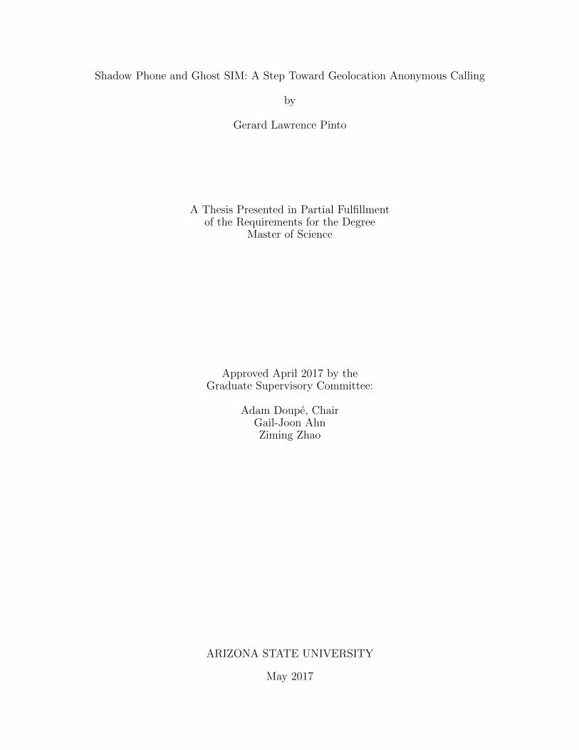
This section is about every component in the GSM network given in the figure 2.1
2.1.1 Mobile Station (MS)
The mobile station is a device that establishes a connection to the GSM network.
It has a transceiver to communicate on a specific frequency band with the network.
The MS authenticates itself to the network with the help of the SIM card which
contains information of the subscriber and this information is also present in the
network. Thus, the network will trust any MS that has a valid SIM card. The MS
5
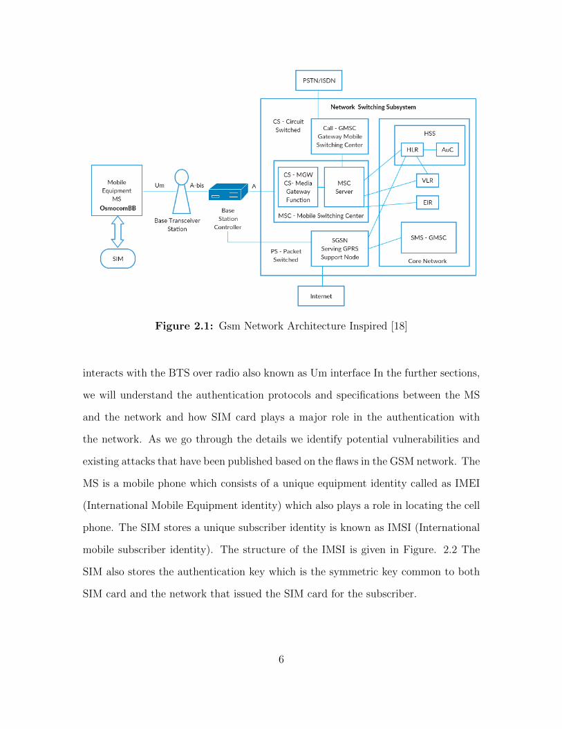
Figure 2.1: Gsm Network Architecture Inspired [18]
interacts with the BTS over radio also known as Um interface In the further sections,
we will understand the authentication protocols and specifications between the MS
and the network and how SIM card plays a major role in the authentication with
the network. As we go through the details we identify potential vulnerabilities and
existing attacks that have been published based on the flaws in the GSM network. The
MS is a mobile phone which consists of a unique equipment identity called as IMEI
(International Mobile Equipment identity) which also plays a role in locating the cell
phone. The SIM stores a unique subscriber identity is known as IMSI (International
mobile subscriber identity). The structure of the IMSI is given in Figure. 2.2 The
SIM also stores the authentication key which is the symmetric key common to both
SIM card and the network that issued the SIM card for the subscriber.
6

Figure 2.2: Structure of IMSI [2]
2.1.2 Base Transceiver Station
The BTS also known as Base Transceiver station is the first network component
in the GSM architecture that communicates with the MS over radio link. A BTS is
a network component which serves one cell and is controlled by a BSC. Among other
things, it is responsible for power and time measurements, and Random Access Chan-
nel (RACH) detection. It then sends that information back to the BSC for analysis.
It is also responsible for error protection, encoding, decoding, and encryption.
2.1.3 Base Station Controller
A set of BTS 2.1.2 is controlled by the BSC. The main objective of the BSC is
to handle radio channel allocation to the BTS. It acts as a relay between BTS and
Mobile Switching Center (MSC). It also controls the handover from BTS to BTS
in case the ME goes out of range from one BTS to another. It communicates with
MSC using the A-interface. When using GPRS it connects to SGGN (Serving GPRS
Support Node).
7

Figure 2.3: Structure of Location Area Code [2]
2.1.4 Mobile Switching Center
The mobile switching center (MSC) is the most important entity in the infras-
tructure. It controls a set of BSC’s. The MSC is capable of performing inter-BSC
handover as well as inter MSC-handover. As mobile phones move, it is important for
the MSC to determine each phones location to effectively facilitate routing commu-
nications between them. For this task, the MSC works with a large database known
as the home location register (HLR), which stores relevant location and other infor-
mation for each MS.
Because accessing the HLR uses many network resources, most operators employ vis-
itor location registers (VLR’s). HLR stores information such as IMSI and MSISDN of
the subscriber. VLR stores temporary mobile subscriber identity (TMSI) of MS that
are in its area covered by the MSC. Within a location area, the MS can freely roam
without updating the VLR. The structure of Location Area Code is given in, Figure
2.3. These are relatively smaller databases, which are integrated with the MSC. Some
carriers deploy one VLR per MSC, while others set up one VLR to serve multiple
MSC’s. MSC plays a major role in locating the cell phone during an incoming call
request to the phone.
2.2 GSM logical Channel: Mode of communication
Now that we have understood the GSM infrastructure, we can go ahead and
understand the initial communication between MS and BTS over the air interface.
8

Since this is done over the Um interface which is radio frequencies. The available GSM
frequencies are shared among a number of mobile carriers. Each of the GSM frequency
bands is divided into multiple carrier frequencies by means of Frequency Division
Multiple Access (FDMA). A BTS communicates with the MS on one of the frequencies
identified by the Absolute Radio-Frequency Channel Number (ARFCN) [20][25][26].
The ARFCN can be considered as a pair of up link and down link frequency used for
communication and sending information [5]. The radio frequency is shared so GSM
uses Time Division Multiple Access (TDMA) as channel access method and divides
physical channels into 8 time slots [20][25][26]. The two categories of logical channels
are control channels and traffic channels.
The three categories of control channels are [20][25][26]:
1. BCH: Broad cast channel provide a unidirectional channel from BTS to MS
transmitted on down link frequency. They act as a beacon channel.
2. CCCH: Common Control Channel is used by the MS to request radio resources
and to access to the mobile network.
3. DCCH: Dedicated Control Channels carry signaling messages related to han-
dover procedures or connection establishment, e.g.,during call setups.
The three important logical channels, of interest are as follows [20][25][26]:
1. PCH: Paging Channel is on the downlink frequency used by the BTS to contact
the MS for an incoming request. PCH is a broadcast request for mobile identity.
2. RACH: Random Access Control Channel is on the uplink frequency and is
requested by the MS to the BTS. Any service incoming or outgoing is done
using a dedicated channel request.
9

3. AGCH: Access Grant Control Channel is used on the downlink frequency. It is
an immediate assignment on the success of RACH with frequency and time slot
correction parameters.
4. SDCCH: Stand alone Dedicated Control Channel is on both uplink and down-
link. Using this channel the MS can initiate a call or any service to the BTS
and vice-versa.
Note :
• For an incoming call the BTS contacts the MS using PCH.
• For an outgoing service the MS contacts the BTS using RACH.
2.2.1 Channel Allocation
On understanding the the channels used by MS and BTS we can further under-
stand the channel allocation procedure with the figure given below:
The steps are as follows (We consider the case when there is an incoming call):
1. The BTS broadcast on the downlink to all subscribers in its area for an incoming
request with a TMSI or IMSI.
2. Mobile Identity Comparison: The stage the MS checks if the requested PCH
with TMSI/IMSI is for itself and send a RACH on the up link. In some cases
when MS is requesting for a service from the network, the BTS can send an
identity request (IMEI) to the MS. In this case, the MS sends IMEI of the
equipment as a response to identity request. This is service is used to blacklist
stolen phones.
10

Figure 2.4: Mobile Channel Allocation
3. After validating the RACH the BTS sends a success intermediate AGCH with
time and frequency correction parameters back to the MS.
4. After correction, the MS then tunes into the ARFCN allocated by the BTS by
sending a SABM Paging response on the SDDCH.
5. The BTS then sends the Acknowledgment back to MS and both continue to
authentication or ciphering setup.
11

Figure 2.5: Mobile Channel De-Allocation
2.2.2 Channel De-allocation
The channel allocation step discussed is done at multiple ocassions viz. The phone
is switched on, calling service, location update service etc. However, the de allocation
step is done when the phone is switched off or losses its network. The figure below
and the explanation will help us better understand the deallocation steps.
1. As we know that MS needs to deallocate or de-register from the network that
has to be done on an up link RACH.
2. On reception of the MS, the BTS allocated an Immediate AGCH with time and
frequency correction parameters.
3. The MS then crafts a GSM packet with IMSI/TMSI detach indication and sends
in on to the network and the channel is released.
4. The channel is released.
12

Figure 2.6: GSM MS Protocol Stack
2.3 Protocol Stack
Now, that we have understood the GSM infrastructure lets understand the Mobile
side of the GSM calling service - The protocol stack. Since, Mobile station has to
adhere to all the protocols of communication to the BTS, it implements a stack that
can perform the respective functions of the protocol as given in the figure 2.6:
• Layer 1: This is the physical layer used in the MS stack. The layer is the
firmware that runs on the phone. More information is provided in 2.3.1
• Layer 2: This layer is known as the Data Link Layer. It supports frame man-
agement for the layer 1 and creates frames from layer3. More information is
provided in 2.3.2
• Layer 3: The Layer3 of the protocol is further subdivided into Radio Resource
Management, Mobility Management and Connection Management (RR/MM/CC)
and described more in 2.3.2
13
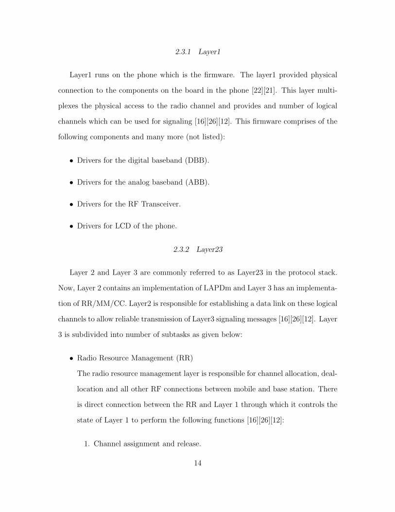
2.3.1 Layer1
Layer1 runs on the phone which is the firmware. The layer1 provided physical
connection to the components on the board in the phone [22][21]. This layer multi-
plexes the physical access to the radio channel and provides and number of logical
channels which can be used for signaling [16][26][12]. This firmware comprises of the
following components and many more (not listed):
• Drivers for the digital baseband (DBB).
• Drivers for the analog baseband (ABB).
• Drivers for the RF Transceiver.
• Drivers for LCD of the phone.
2.3.2 Layer23
Layer 2 and Layer 3 are commonly referred to as Layer23 in the protocol stack.
Now, Layer 2 contains an implementation of LAPDm and Layer 3 has an implementa-
tion of RR/MM/CC. Layer2 is responsible for establishing a data link on these logical
channels to allow reliable transmission of Layer3 signaling messages [16][26][12]. Layer
3 is subdivided into number of subtasks as given below:
• Radio Resource Management (RR)
The radio resource management layer is responsible for channel allocation, deal-
location and all other RF connections between mobile and base station. There
is direct connection between the RR and Layer 1 through which it controls the
state of Layer 1 to perform the following functions [16][26][12]:
1. Channel assignment and release.
14

2. Channel Change.
3. Channel Mode and Ciphering.
4. Handover between base stations.
5. Frequency usage, reassignment, hopping.
6. Measurement reports.
7. Power control and timing advances.
• Mobility Management (MM)
The MM is responsible for handling aspects relating to the mobility of the
handset [16][26][12].
1. Location update when the mobile movies into a new location area and
periodically as required.
2. Attach /detach wen the mobile is powered up and down.
3. Authentication with SIM Manager.
4. Handling the temporary ID (TMSI) with the SIM manager.
5. Respond to request fo ridentity (IMSI or IMEI) by the network.
• Connection Management (CM)
The connection management is split up into three tasks: call control, supple-
mentary services and short message services [16].
1. The call control is responsible for:
– Attach /detach wen the mobile is powered up and down.
2. Supplementary Services (SS) is used for providing services like call barring,
call redirection etc.
15

Figure 2.7: Network Authentication
3. Short Message Services (SMS) is used for transmission of messages and
reception from point-to-point. They are also used for broadcast messages.
2.4 Network Authentication
Once we have established connection and received an ARFCN from BTS, we
proceed with authentication, with the network. The authentication is performed with
the SIM card present inside the phone. Internals of the SIM card is described detailed
in section 2.5. In this section we will describe just minimalistic information about
the modules used in the SIM card for network authentication. The authentication
procedure with the network is provided below with referencing Figure 2.7
Steps for authentication are given below, we consider a simple case where the MS
is switched on and request for a calling service is initiated:
16
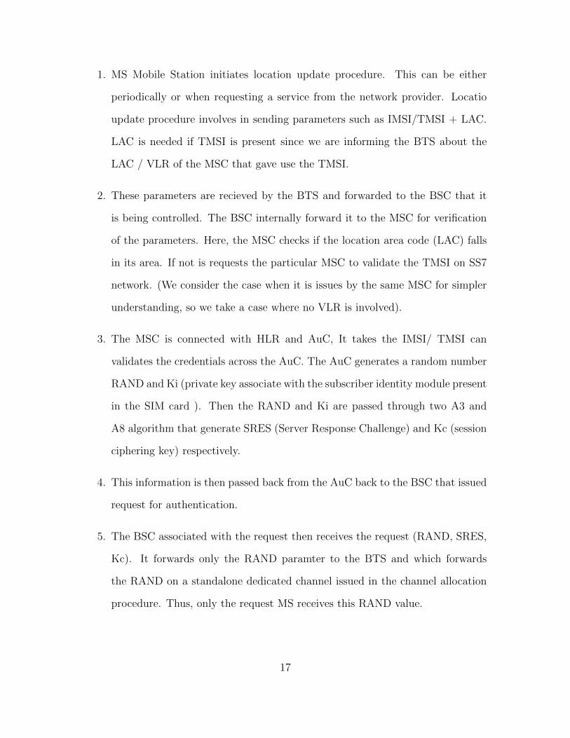
1. MS Mobile Station initiates location update procedure. This can be either
periodically or when requesting a service from the network provider. Locatio
update procedure involves in sending parameters such as IMSI/TMSI + LAC.
LAC is needed if TMSI is present since we are informing the BTS about the
LAC / VLR of the MSC that gave use the TMSI.
2. These parameters are recieved by the BTS and forwarded to the BSC that it
is being controlled. The BSC internally forward it to the MSC for verification
of the parameters. Here, the MSC checks if the location area code (LAC) falls
in its area. If not is requests the particular MSC to validate the TMSI on SS7
network. (We consider the case when it is issues by the same MSC for simpler
understanding, so we take a case where no VLR is involved).
3. The MSC is connected with HLR and AuC, It takes the IMSI/ TMSI can
validates the credentials across the AuC. The AuC generates a random number
RAND and Ki (private key associate with the subscriber identity module present
in the SIM card ). Then the RAND and Ki are passed through two A3 and
A8 algorithm that generate SRES (Server Response Challenge) and Kc (session
ciphering key) respectively.
4. This information is then passed back from the AuC back to the BSC that issued
request for authentication.
5. The BSC associated with the request then receives the request (RAND, SRES,
Kc). It forwards only the RAND paramter to the BTS and which forwards
the RAND on a standalone dedicated channel issued in the channel allocation
procedure. Thus, only the request MS receives this RAND value.
17

6. The MS recieves a system information message with this RAND value. Now
SIM card present inside the phone has the same Ki (private key which is present
with Auc) and the same encryption/signature algorithms A3/A8.
7. It takes the RAND and performs the same operation as done by the AuC in
steps 3. Thus, in its response it gets RES (Response to challenge computed by
the RAND send by the network) and Kc (Ciphering Key).
8. The MS sends back the RES computed using Ki present in the SIM card. If
RES == SRES, authentication is successful else authentication failure message
is send back to the MS.
9. The BSC then issues the Ciphering Mode present the options available at the
MSC such as A5/3, A5/1 and A5/0 (no ciphering), in order of the their appear-
ance. In GSM other than these algorithms no other algorithm is acceptable.
This message is sent in CLEAR over the stand alone dedicated channel.
10. The MS responds with RR Ciphering Mode complete.
11. The final stage of authentication is when the BSC associate this location update
procedure with a TMSI. So then next time the MS sends TMSI instead of
IMSI and both communicate with each other with TMSI thus hidding the true
identity of the subscriber. Since, TMSI is temporarily issued and frequently
updated as compared to IMSI that is stored inside the SIM card. The next
paging request will be issued with TMSI, the attacker TMSI with a particular
subscriber. Although there are ways to do this described in later sections.
Other cases would be as follows:
18

1. If authentication is triggered in a different network provider in a different
PLMN, MSC contacts the other network providers MSC for authentication pa-
rameter validation.
2. TMSI re-use does not trigger authentication procedure and ciphering key Kc is
the same.
3. If TMSI was previously authenticated by the same BSC considering MCC/MNC
and Cell ID (LAC). In location update procedure, TMSI is passed on instead
of IMSI.
2.5 Subscriber Identity Module (SIM) card
SIM is a mandatory security module located in the mobile phone. It is not holds
subscriber identity information as well as other information stored. It has a per-
manent memory storage and capacity for calculation. SIM card is smart card with
microprocessor with the following modules CPU, ROM, RAM, EPROM and Serial
communication. It has a hierarchical fixed file structure format. It consists of the
following three types of files system.
• MF Master File is the root of the SIM card that contains dedicated and ele-
mentary files.
• DF Dedicated Files contain network related information.
• EF Elementary Files contains data for the application and are located below
the DF. They may be linear or cyclic series of bytes of fixed and variable record
size.
19

The GSM 11.11 specification defines 22 operational commands for the SIM. For
our research model we used just three commands while in OsmocomBB in built card
reader all have been implemented according to the GSM specification [29].
• SELECT select a file MF, DF, EF.
• READ BINARY Read from a file with a transparent file structure.
• GET RESPONSE Command is requesting data from the smart card. It falls
under the miscellaneous command.
• UPDATE BINARY Update the file with a transparent file structure.
There is a lot of information on the SIM stored in file systems described above we
can access/update them with commands. Now, the file identifiers help us to identify
the location of the field in the file system.
Table 2.1: Essential Sim Card Files Used by OsmocomBB Built in Sim Card
Reader [29]
File System FID Description Coding
Bytes
Example
MF.EFICCID 2FE2 ICC unique identifica-
tion number of SIM
10 890126062
2742916999
DFGSM.EFIMSI 6F07 International Mobile
Subscriber Identity
9
DFGSM.EFLOCI 6F7E MCC|MNC|TMSI 11
MCC(3) |
MNC(3) |
TMSI(8)
310 | 260 |
87D6
20

DFGSM.EFKc 6F20 Ciphering Session Key 9 5daa1192
25e73c8600
DFGSM.EFPLMNsel 6F30 Public Land Mobile
Network Selector
MCC | MNC
(variable)
3n, n ≥ 8
310 (USA)
| 320 (T-
mobile)
DFGSM.EFHPLMN 6F31 Home PLMN (Time
for searching home
network )
1 1
DFGSM.EFSPN 6F46 Service Provider
Name
17 -
ACC 6F78 Access Control Class 0200 0200
DFGSM.EFFPLMN 6F7B Forbidden PLMN (f
indicates not used)
12 ffffff ffffff ffffff
ffffff
DFTELECOM.EFMSISDN 6F40 Subscriber Phone
number
linear
fixed
record
size (n +
14)
+16025965697
DFTELECOM.EFSMSP 6F42 Text Message Param-
eters
linear
fixed
record
size (28 +
n)
-
21

After understanding the above table the private key Ki used in the network au-
thentication chapter 2.4 is not stored in the file system. It is not a READ ONLY
field. It is a compute only field. We cannot retrieve the Ki by any software. This
is the primary reason why SIM card cloning is difficult. Although there are ways to
clone SIM which will not be discussed here since it is out of scope for this research.
2.6 Related Projects
Now that we have understood GSM architecture, protocol stack, channel alloca-
tion and deallocation, network authentication and internals of the SIM card. It is
time to build our own phone. Todays phones the boot loaders are locked, all source
code for drivers to the base band processors are not available. Source code for Digital
Signal Processing is hard coded on the ROM present in the phone. There is no source
code either. In such situation in the telecommunication domain, there is no way we
can understand or reverse engineer latest phones or build our own.
However, in such a situation we are just left with OsmocomBB stands for Open
Source Mobile Communication Base Band. OsmocomBB is an implementation of the
mobile-phone-side GSM protocol stack, including Layer 1 (TDMA)[22][21] through
Layer 2 (LAPDm) and Layer 3 (RR/MM/CC) [7]. OsmocomBB is compatible with
with phones that have the following components:
• Hardware Calypso Digital Base Band chip.
• Rita radio frequency chip
• Iota Analog baseband chip
Most compatible phones that work with OsmocomBB are listed below in accordance
with the official site [10].
22

• MotorolaC115/C117 (E87)
• MotorolaC123/C121/C118 (E88)
• MotorolaC140/C139 (E86) - Our target phone
• MotorolaC155 (E99)
• MotorolaV171 (E68/E69)
• SonyEricssonJ100i
2.6.1 OsmocomBB
OsmocomBB application comes with various modules. The two major modules
are
• running baseband firmware on the phone (Layer1)[22][21]
• running on Host machine (Layer23), and communicating with Layer1 over serial
UART cable.
Applications on the host machine have several modules built in it such as [11]:
1. Firmware management software (loading, flashing...) etc.
2. GSM Layer 2/3 applications
The following sections will describe a view of the some of the essential modules that
will help in understanding the software. The figure 2.8 gives us the detail view of the
components used in the OsmocomBB software.
23

Figure 2.8: Open Source Mobile Communication Base Band
2.6.2 Components of OsmocomBB
The following section details about some of the components in OsmocomBB and
also describes about the flow of running your own GSM protocol stack.
1. Osmocom: It is a console tool for interfacing the baseband firmware one the
phone via the serial port to applications running on host machine.
The command used for loading the firmware on to the phone is:
cd osmocom-bb/src
./host/osmocon/osmocon -p /dev/ttyUSB0 -m c140xor
-c /root/osmocom-bb/src/target/firmware/board/
compal e86/layer1.highram.bin
The layer1.highram.bin is compiled using GNU CC [22] [21].
24

2. Osmoload: The command line tool is used to write, dump and examine flash
memory of the phone. The layer1 firmware is compiled using GNU Cross Com-
piler (CC).
3. Layer1 Firmware: This includes drivers for Rita RF, ABB, DBB and also for
power measuremnets, carrier bit TDMA synchronization, Recieve and transmit
normal burts on SDCCH, Transmit RACH bursts Automatic Rx gain control
and frequency hoping. Asynchronous and synchronous part. Sercomm - A
HDLC multiplexer for RS232 to Host PC [12].
4. UART: Universal Asynchronous receiver transmitter. It is a computer hardware
device for asynchronous serial communication in which the data format and
transmission speeds are configurable. The electric signaling levels and methods
(such as differential signaling, etc.) are handled by a driver circuit external to
the UART.
5. Layer23 Implementation: Implementation stack of RR/MM/CC that runs on
host machine and connects to layer1 with serial cable UART.
6. Mobile Application:
cd osmocom-bb/src/host/layer23/src/mobile/
./mobile [-m | -i 127.0.0.1]
• mobile.cfg: Mobile configurations that need to be loaded in order to use
the OsmocomBB Layer23 mobile application via VTY.
• VTY Telnet: This is an external interface to control OsmocomBB call
control application present in Layer3.
• GSM-TAP: GSMTAP is a pseudo-header that encapsulates the Um air
interface signaling messages sent to and from BTS onto localhost. These
25
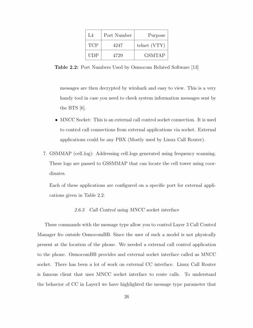
L4 Port Number Purpose
TCP 4247 telnet (VTY)
UDP 4729 GSMTAP
Table 2.2: Port Numbers Used by Osmocom Related Software [13]
messages are then decrypted by wirshark and easy to view. This is a very
handy tool in case you need to check system information messages sent by
the BTS [6].
• MNCC Socket: This is an external call control socket connection. It is used
to control call connections from external applications via socket. External
applications could be any PBX (Mostly used by Linux Call Router).
7. GSMMAP (cell log): Addressing cell logs generated using frequency scanning.
These logs are passed to GSSMMAP that can locate the cell tower using coor-
dinates.
Each of these applications are configured on a specific port for external appli-
cations given in Table 2.2:
2.6.3 Call Control using MNCC socket interface
These commands with the message type allow you to control Layer 3 Call Control
Manager fro outside OsmocomBB. Since the user of such a model is not physically
present at the location of the phone. We needed a external call control application
to the phone. OsmocomBB provides and external socket interface called as MNCC
socket. There has been a lot of work on external CC interface. Linux Call Router
is famous client that uses MNCC socket interface to route calls. To understand
the behavior of CC in Layer3 we have highlighted the message type parameter that
26

needs to be sent from an external CC application to the OsmocomBB MNCC socket
interface in Table 2.3
2.6.4 Osmo-sim-auth
osmo-sim-auth is a small python script that can be used with a PC-based smart
card reader to obtain GSM/UMTS authentication parameters from a SIM/USIM
card [9]. In our attack model we need the SIM card outside the phone. The reason
being we want the same SIM card to authenticate on another phone. Thus, making
it look like the user is present at that location and not the original called location.
This behavior can only be achieved if SIM card is deployed as a service and can be
accessed by OsmocomBB compatible phone. The phone would need to remote access
the SIM card information in order to connect and authenticate to the network. All
SIM card access is done by the Mobility Management layer by sending APDU (Ap-
plication Protocol Data Unit) commands to layer1 over UART which then fires the
these commands on the SIM card and response is set in Layer23 to send to the BTS.
In order to emulate the internal SIM card functionality we use osmo-sim-auth as an
open source project and re-write all SIM API’s so we can expose SIM as a service
which then can be used by any phone.
2.6.5 Tor
Tor also known as Onion Routing is a well documented open source project that
aims at achieving location anonymity from traffic analysis [19]. We deploy our SIM
card service (osmo-sim-auth) on Tor, by creating a hidden service in Tor [19]. Tor
is basically building a circuit to have an anonymous communication service. Where
each hop in the circuit is aware of the next hop in the circuit and not the one after
27
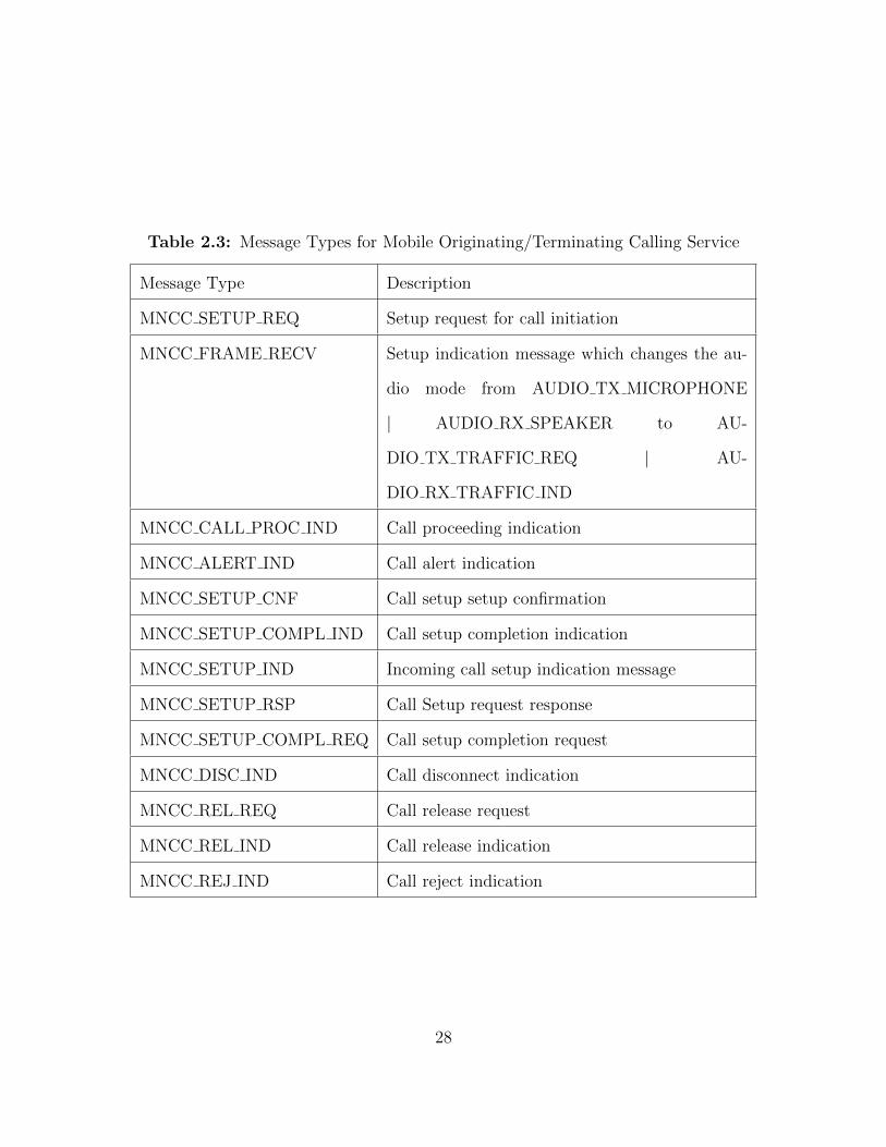
Table 2.3: Message Types for Mobile Originating/Terminating Calling Service
Message Type Description
MNCC SETUP REQ Setup request for call initiation
MNCC FRAME RECV Setup indication message which changes the au-
dio mode from AUDIO TX MICROPHONE
| AUDIO RX SPEAKER to AU-
DIO TX TRAFFIC REQ | AU-
DIO RX TRAFFIC IND
MNCC CALL PROC IND Call proceeding indication
MNCC ALERT IND Call alert indication
MNCC SETUP CNF Call setup setup confirmation
MNCC SETUP COMPL IND Call setup completion indication
MNCC SETUP IND Incoming call setup indication message
MNCC SETUP RSP Call Setup request response
MNCC SETUP COMPL REQ Call setup completion request
MNCC DISC IND Call disconnect indication
MNCC REL REQ Call release request
MNCC REL IND Call release indication
MNCC REJ IND Call reject indication
28
it or before, thus anonymize the network flow. The hidden service builds a circuit
to each of the introductory points (IP) and tells them to wait for a the incoming
request. The user using such a request looks up for the onion service and connects
the OR as the rendezvous point (RP). The user then randomly chooses a rendezvous
cookie to recognize the hidden service. Then the user sends a message to the hid-
den service encrypted with the public key. The message contains details about the
user, rendezvous cookie and start the Deffie Hellman handshake for symmetric key
encryption. If the hidden service wants to address the request it creates a circuit
to the users rendezvous point (RP) and sends a message containing second half of
the Deffie-Hellman handshake, rendezvous cookie thus ensuring both have the same
symmetric key for encryption. Now the rendezvous point (RP) cannot trace back to
the user neither the hidden service as both have build a circuit around the RP. Now,
we can securely communicate with the hidden service without revealing our location
and the hidden service. [19]
29
Chapter 3
DESIGN
The goal of this thesis is to design a scheme for privacy demanding users can make
a call without revealing their actual location to the TSP’s network. The scheme can
be introduced as a Shadow Call. Shadow call is a regular phone call that is made
through another phone. In the Figure 3.1 from the Telephony Service Provider’s
(TSP) perspective, a call is initiated from a phone that has valid authentication and
is located by the nearest cell tower (BTS).
GSM Calling is a service that is provided by any TSP who knows the location
of the caller and also successful authenticates itself to the TSP’s network. Every cell
tower (BTS) has a physical area coverage to which it can provide a range. Now, the
caller must be in this area range to make a call after authentication. Now the cell
phone is implicitly located by the TSP. This is a fundamental problem of location
privacy that cannot be achieved in the calling service provided by the TSP. To over-
come this problem, in this thesis we design a Shadow Phone that can authenticate
to the network remotely and make a call on our behalf without revealing our actual
physical location to the Telephone Service Provider’s (TSP) network.
If we take an example in Figure 3.1 we need a shadow phone that connects to
the network, remote authenticate itself to the network using a remote SIM card and
make a call using a remote phone. Assume that such a phone is present in Phoenix
(PHX), and we are physically located in New York (NY). Using the current phone
in New York (NY), we initiate the process of authentication to the shadow phone in
Phoenix (PHX) using our SIM card present in New York (NY). This way the SIM
card is not physically located in Phoenix and authentication with the network is done
30

Figure 3.1: Idea
using our SIM card present in New York. After a successful authentication handshake
with the TSP’s network (in PHX), we further start the calling procedure using our
phone present in New York (NY). Our phone in NY sends all the parameters that
the shadow phone needs to start the calling procedure to the TSP’s network. So,
for the TSP’s perspective, they believe that the phone is authenticated by the phone
in Phoenix and the call is located and originated from Phoenix. However, in our
implementation, we are not physically located in Phoenix.
Apart from this, there are two major challenges that need to be addressed, if the call
is initiated from the shadow phone.
31

C.1 The shadow phone should not know the physical location of the true caller. In
our case, it is New York.
C.2 The delay of remote SIM card authentication should be acceptable to the TSP’s
network.
We have addressed this challenge in Chapter 4 implementation.
32

Chapter 4
IMPLEMENTATION
This chapter addresses the two challenges, the shadow phone should not know the
physical location of the true caller C.1 and the delay of remote SIM card authentica-
tion should be acceptable to the TSP’s network C.2. To address these challenges, we
need a shadow phone. In the previous section, we understood that OsmocomBB is
an open source baseband implementation of a 2G phone. This helps us to control the
phone’s protocol stacks, and we are focused on is Layer3. Layer3 of the protocol stack
controls the SIM card initiation (often known as SIM card manager), authentication
with the TSP’s network, and mandatory steps in the call control application. To have
the shadow phone make the call on the user’s behalf, we need to control Layer 3 from
an external interface. OsmocomBB has a socket implementation to interface the call
control application in Layer3 from an external system.
The user of such a model needs to send their mobile phones SIM card details to
the Shadow Phone in order to authenticate to the network. There is a big limitation is
current phones as the bootloaders are locked, therefore we cannot analyze the phones
for security purposes. Thereby we do not have access to the baseband implementation
of any latest phone. Every phone has two processors application Processor (AP) and
baseband processor (BP). SIM card details for authentication handshake are fetched
by the baseband processors. Most of the baseband processor code is propitiatory and
no source code is available for the study of security. Thus, for our current implemen-
tation, we fetch the SIM card information using a SIM card reader. This is achieved
using osmo-sim-auth, a python script to access SIM card GSM authentication param-
eters. To run the SIM card python application (osmo-sim-auth), we use a SIM card
33

reader. Any smart card reader that is compatible with pcsc-lite and installed python
program with the pyscard library can be used to read the SIM card. We can verify
this setup using ‘pcsc scan’ tool included with pcsc-lite [9] which will read the SIM
card only if the configurations are met. Initially, osmo-sim-auth was pre-built with
GSM authentication code, we added all SIM API’s that a GSM phone needs to op-
erate and communicate with the network [1]. We then deployed this osmo-sim-auth
application to run on a SIM card reader on a Raspberry PI.
After SIM card setup is complete we send all of this information to the shadow
phone over TCP/IP network. To achieve location anonymity of the subscriber, we
send the SIM card details over Tor [19]. Tor (The Onion Router) is well established
open source project for achieving anonymity over the web. It conceals user’s loca-
tion from traffic analysis and network surveillance. Using Tor we achieve location
anonymity of the subscriber which is the SIM card from the Shadow Phone. All SIM
card information is sent over the Tor network.
For achieving anonymity of the SIM card service, we create a hidden service in
Tor [3]. This hidden service is deployed on a Raspberry PI. In an ideal case, the sub-
scriber would use their own SIM card present in the phone to connect to the Shadow
Phone and share SIM card information. However, this is currently not possible due to
the fact that baseband implementation of latest phones is proprietary and no source
code is available. In our implementation, the subscriber uses their SIM card into a
SIM card reader. This SIM card reader can read all the mandatory information and
send it across the Tor network onto the Shadow Phone.
After setting up the Motorola Phone which is compatible with OsmocomBB, we
ensure the firmware Layer1 is downloaded onto the phone and Layer23 running on
host machine. They communicate with each other using a UART cable. This setup
we use as our Shadow Phone without the SIM card. We have developed a python
34
application ‘phone controller’ running alongside OsmocomBB. This program is an
external interface for the user to control the phone remotely. This program is acces-
sible over the Internet and thus accessible via Tor. Whenever the subscriber wants
to make a geolocation anonymous call she sends her SIM card information using the
SIM card hidden service. This service internally connects to the ‘phone controller’
that internally initiates the calling procedure to the Shadow Phone. Thus, we have
addressed the first concern C.1.
The remote SIM card information is sent over Tor network. Tor is well known for
network latency since it has a number of hops before reaching the end destination.
In the authentication handshake between cell tower (BTS) and mobile phone (MS),
the BTS sends a challenge to the MS, to which the response challenge is computed
by the SIM card and sent back to the network. In our case, the SIM card service
is deployed over Tor and the shadow phone (without SIM card) fetched the SIM
card details from the SIM card hidden service on Tor network. Thus, we carried
out multiple experiments to find the maximum acceptable time delay which on an
average rounded up value is 4 sec, which is reasonable for a Tor connection. We per-
formed experiments over Tor on a real network with Mobile Network Code (MNC)
310 which identifies as T-Mobile and Mobile Country Code (MCC) 260 which identi-
fies as United States of America (USA). These experiments worked well without the
network rejecting the request an authentication timeout. This experiment addresses
our second concern C.2.
The user of such a model uses the following steps in order to make a Geo-Location
Anonymous Call:
1. Start (short push) the phone to download the firmware. Now, the phone is
scanning for frequency/power scan to the nearest cell tower (BTS).
35
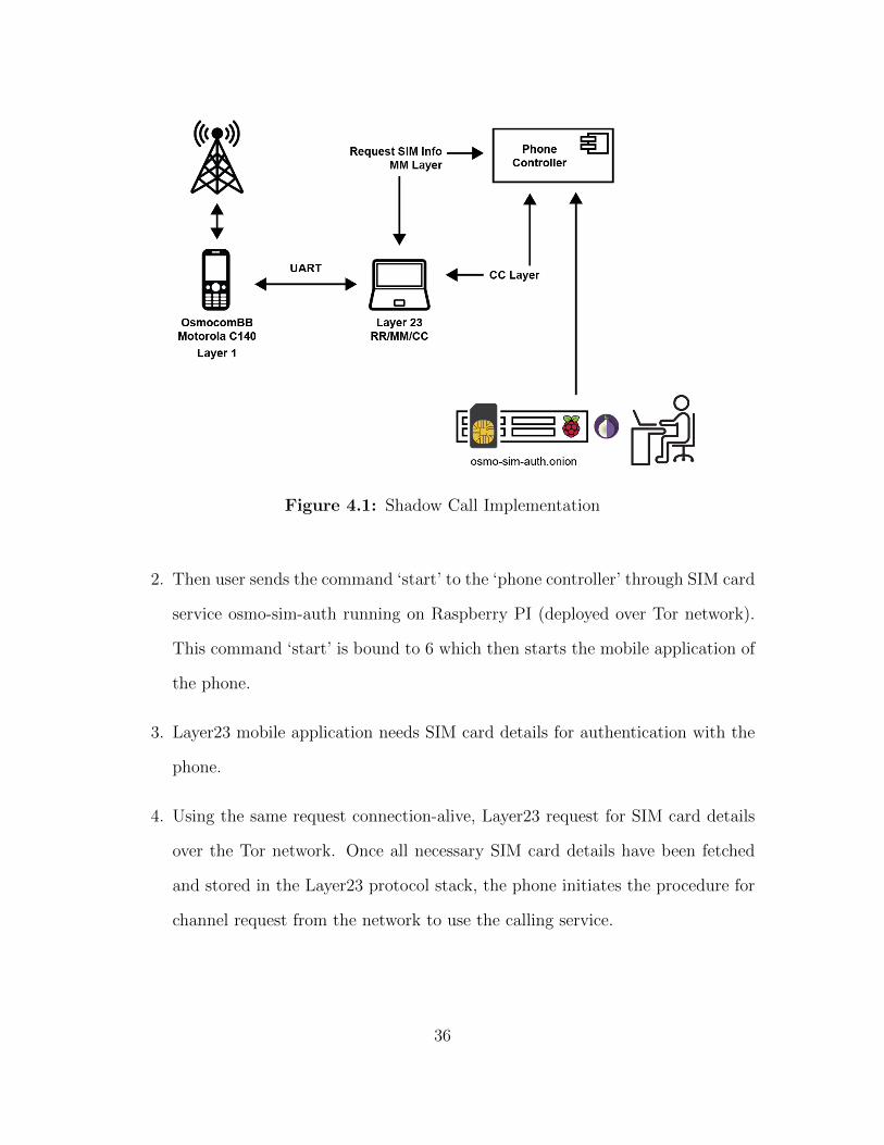
Figure 4.1: Shadow Call Implementation
2. Then user sends the command ‘start’ to the ‘phone controller’ through SIM card
service osmo-sim-auth running on Raspberry PI (deployed over Tor network).
This command ‘start’ is bound to 6 which then starts the mobile application of
the phone.
3. Layer23 mobile application needs SIM card details for authentication with the
phone.
4. Using the same request connection-alive, Layer23 request for SIM card details
over the Tor network. Once all necessary SIM card details have been fetched
and stored in the Layer23 protocol stack, the phone initiates the procedure for
channel request from the network to use the calling service.
36

5. Now, we begin camping on a cell tower (BTS), initiates a call using ‘call’ com-
mand through SIM card service osmo-sim-auth. This command in ‘phone con-
troller’ starts the external call control application on the MNCC socket which
is exposed in OsmocomBB. Thus, the user is not present at that location to
send voice.
6. Once all mandatory information is setup, the phone connects to the nearest cell
tower. Request authentication is done using remote SIM card service (osmo-
sim-auth). The call can thus be initiated using this remote SIM card service.
7. Now that the authentication is complete and we are camping on the cell tower,
we start the call using procedures described in 2.3. These procedures are imple-
mented and external call control interface is developed to send and receive voice
over Tor to/from the GSM network. Thus, making the whole setup accessible
to the caller as if she is present at the location.
Now, that we have the whole understanding of the model and procedural flow
of geolocation anonymous call model, the Figure 4.2 helps us understand the overall
idea. After this implementation, from the TSP’s perspective (lower diagram), we
are present in Phoenix (PHX), since we authenticate to the cell tower of the TSP’s
network in Phoenix (PHX). However, all information is sent over Tor onto the shadow
phone. If the TSP has to locate the call, it will end up locating at Phoenix (PHX)
and not New York (NY), since authentication is done by the shadow phone present
in Phoenix (PHX). Voice is also sent and received to/from shadow phone over Tor by
the external call control application. This setup does not require to have any change
from the telephone service provider’s network.
37

Figure 4.2: Shadow Call Overall Idea
4.1 Software Patches
Preliminary open source software projects used are:
• OsmocomBB (Open Source Mobile Communication Baseband)
• osmo-sim-auth (Python application to read SIM card information)
Changes that were made to build the attack model:
1. The Mobility Management (MM) in Layer3 of OsmocomBB is used to send
APDU commands for SIM card information request, this part of MM has been
commented and we have added socket communication to accept the request
38
from remote SIM card service (osmo-sim-auth) deployed over Tor network on a
Raspberry PI.
2. SIM API’s have been written in python and integrated with osmo-sim-auth
GSM authentication, thus making osmo-sim-auth a complete remote SIM in-
formation project.
3. Creation of Hidden Service on Tor network to deploy osmo-sim-auth python
application to run with a SIM card reader.
4. A python web application ‘phone controller’ that controls the Layer 3 Mobil-
ity Management (MM) in specific SIM card manager and Call Control (CC)
application to accept the request from the IP network.
5. A python application ‘call control’ used by the user to initiate a call using the
external (CC) application in Layer 3 of the protocol stack in OsmocomBB.
This is the main application used by the user to start and end a Geo-Location
Anonymous Call.
39

Chapter 5
EVALUATION
We evaluate the whole setup based on multiple criteria given below. Now, that we
have addressed both are challenges the shadow phone should not know the physical
location of the true caller C.1 and the delay of remote SIM card authentication
should be acceptable to the TSP’s network C.2 in the implementation Chapter 4, we
evaluate them on certain criteria given below.
5.1 Experimental Setup
The following section details the experimental setup hardware and software used
to build the model.
Figure 5.1: Experimental Setup
40
5.1.1 Hardware
From Figure 5.1, we have used a laptop to run OsmocomBB software which is con-
nected to the Motorola phone C140 via the UART cable. This setup is the shadow
phone setup. The laptop can be replaced with a Raspberry PI as running Osmo-
comBB is not an intensive task. A SIM card reader containing the user’s SIM card
is plugged into the Raspberry pi which is the hidden SIM card service.
5.1.2 Software
OsmocomBB Layer23 runs on the laptop and Layer1 is downloaded on the phone
using the UART cable. SIM card reader runs the program osmo-sim-auth which is
deployed as a hidden service on Tor. All open source projects are used on the exper-
imental setup. Also, there is no change required in the telephone service provider’s
network infrastructure.
5.2 Experimental Results
The criteria to be addressed can be given below:
• Deploy ability : The setup phone, SIM card, SIM card reader, and other
hardware cost is cheap. Both OsmocomBB and osmo-sim-auth are open source
projects, their source code is available to use and modify. We require no change
in the TSP’s network infrastructure. All of this, setup was tested on the live
network with MCC 310 and MNC 260 with a T-Mobile SIM card. We have only
tested the calling service provided by the TSP’s network infrastructure. osmo-
sim-auth has been deployed as hidden service. Hidden service in Tor does not
need a domain name, hosting platform. etc like other web-facing applications.
Thus, we deployed the SIM card hidden service on Tor network running on a
41

raspberry pi. This deployment did not have much configuration needed and did
not involve any external 3rd party entities.
• Location of the Caller : A Python application ‘phone controller’ controls
the phone and accepts requests over Tor for initiating a geolocation anonymous
call. Thus, the user is not present at the location of the phone and the SIM
card program. Both of these can be accessed from a different geographical
location as both are IP facing applications. We deployed the SIM card on the
raspberry pi in a different location over the same WIFI network, and tested the
Tor connectivity between OsmocomBB Motorola phone and osmo-sim-auth; We
noticed that when the mobile phone fetches information from osmo-sim-auth
for the SIM card details to authenticate itself to the network. We performed
a number of experiments to ensure that the communication of Tor is reliable,
we did find a number of instances where Tor connection fails when the phone
accesses SIM card information over Tor. Each time the experiment performed
included Tor and a majority of cases worked well. We controlled the phone
using ‘phone controller’ remotely, by starting the phone. Each phone call made
through the phone was not performed physically at that location but automate
using ‘phone controller’ that was accessed through a Tor network. Each step in
the process described in the Chapter 4, was automated and thus, the user did
not have to physically be present at that location to make a call.
• Accessibility : Once the setup is deployed can be accessed from any geograph-
ical location with Internet. We deployed every component over the Internet.
The SIM card program running on the Raspberry pi is exposed via Tor by cre-
ating a hidden service. Shadow phone is exposed via ‘phone controller’ over the
Internet. The shadow phone can be controlled remotely and also accepts Tor
42
connection request from SIM card reader program (osmo-sim-auth). We then
send ‘start’ command to ‘phone controller’ over TCP/IP by not physically being
at that location. Once the phone starts, it automatically fetches information
from the SIM card service, that we initiated the ‘start’ command from, now
both of these can be controlled using TCP/IP request, this making it accessible
from any geographical location provided the user has access to the Internet
• Authentication Latency : We monitored the latency in Tor, since the de-
lay in authentication will not be accepted to the TSP’s network. We ran the
whole setup a number of times to find out the maximum acceptable time delay
in the authentication handshake protocol explained in section 2.4. Once the
authentication was successful over Tor, we did not need the SIM card service
from there on, since the ciphering key obtained is stored in the Layer23 stack
running on the host machine and is passed to Layer1 during ciphering of the
call. This latency plays a crucial role in our setup to make a geolocation anony-
mous call. We carried out a number of experiments with various time delays of
2sec, 3sec, 5sec and so on, and after performing these experiments with these
values, we draw our conclusion that the response to the challenge that is ini-
tiated to the network can be responded with a delay of average rounded up
value of 4 seconds. We then set up the SIM card service with and Tor and
noticed that every authentication handshake was successful over Tor. We did
encounter a very few number of requests failing due to delay in authentication.
This was negligible compared to the number of times it the protocol handshake
was successful. Thus, incorporating Tor to provided anonymity did not have
any significant problems in making a geolocation anonymous call through the
shadow phone.
43

Chapter 6
DISCUSSION
This section of the document details about the related work carried out in the area
of telecommunication security and future scope that can address to build a better
model.
6.1 Arguments
This section provides a list of arguments that can be discussed after understanding
the Geo-Location Anonymous Calling model:
• Decouple SIM card from the phone:
SIM card ensures the authenticity of the user with the network. This authen-
tication handshake between MS and BTS leaks the location of the caller. By
decoupling the SIM card we can now reuse the SIM card with another phone in
another geographical location. This will cause the entry in the VLR of the GSM
network to change to the new location. This randomization helps is rendering
location switch in a very short time. Although, the observer can analyze such
a change but will not effectively be able to trace back to the attacker.
• SIM card deployed behind Tor :
SIM card as service is deployed on Tor network for anonymity of the SIM card
location. Thus, it will be hard for the observer to trace the SIM card.
• External Call Control application:
The external call control application helps the user to make and receive voice
44

calls without being at that location. The call will be ideally placed over Tor,
thus making it hard to trace back. This setup causes the observer to view it as
a local GSM call. However, the user is not present at the location where GSM
call was initiated.
• IMEI randomization:
This is related to future scope. In order to hide the identity of the phone, we
can randomize the IMEI. Having many phones and somehow these phones are
located in different geographical areas that are not linked to each other can
achieve better anonymity of the user.
• Geographically distributing the phone and SIM cards :
This is the ideal case where many phones are distributed in a different geo-
graphical location at best at different countries which would then act as nodes
in the calling service. Each SIM card randomly uses a different IMEI for each
call. Thus, making it difficult to locate the phone itself.
• Hardware replacing Motorola and Software replacing OsmocomBB This is high-
lighted in Table 6.2. Here we discuss the arguments related to it. The whole
setup can be performed on latest phones 3G/4G. All we need is SIMtrace [14]
an open source project to tap communication between mobile (MS) and SIM
card. This project could be modified to be the ‘phone controller’ that accepts
the request from Tor to initiate a Geo-Location Anonymous Call in GSM.
6.2 Related Work
This section describes about the related work in analyzing security aspects of
GSM [17][24][23]. Herald Welte [28] et. al have developed several open source projects
and they can found at [7]. These projects aim at better understanding the internals
45

of GSM and its security areas. Our project mainly revolves around SIM card as that
is the key part for location identification. There has been previous efforts in under-
standing SIM card using projects like py-sim [4], osmo-sim-auth [9] and SIMtrace [14].
These projects are developed to understand the internals of communication between
mobile phone (MS) and SIM card. We leverage these projects in our model. By
deploying these services behind Tor ensures that location of these SIM card services
hard to trace and thus gives us the liberty to make a location anonymous call.
6.3 Future Scope
This research has not only given us the liberty to make a Geo-Location Anonymous
Call but also protect our location. We could use SIM card as a service deployed over
Tor. Currently, this model does not have a full support to send voice from an external
interface over Tor and on to the phone. GSM has a specific encoding also sending
voice over Tor will have a latency involved. We plan to incorporate a full fledged
voice system and calculate the latency.
Along with this we plan to test telecommunication network operators behavior
as we have decoupled the SIM card from the phone, testing scenarios will give us
insights on how certain rules have been configured by the telecommunication network
operators. Some of the scenarios highlighted can be given in Table 6.1 Some of
the changes that could be done to the existing model to make it more effective is
described in Table 6.2.
46

Table 6.1: Test cases for TSP’s network anomalies
Classification Description
Location Anomaly Call originates in USA at 5:00pm, after a few min-
utes users call originated at 5:02pm in Australia
same SIM card
Different Network Anomaly Use the same SIM card to initiate a call on two differ-
ent TSP’s networks (T-Mobile in USA & Vodafone
in India)
Same Network Anomaly Use the same SIM card on different cell tower (BTS)
on the same TSP’s network
TSP’s roaming capabilities Validate the networks claim for roaming services by
automate roaming test
47
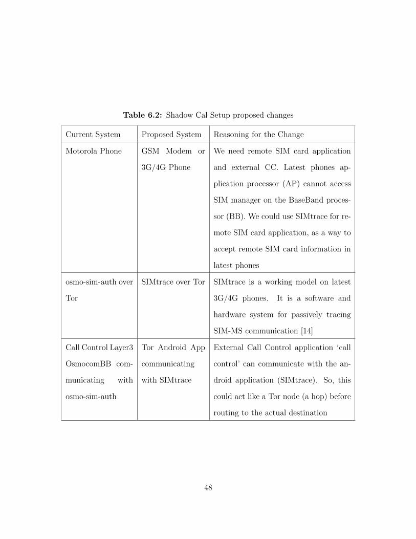
Table 6.2: Shadow Cal Setup proposed changes
Current System Proposed System Reasoning for the Change
Motorola Phone GSM Modem or
3G/4G Phone
We need remote SIM card application
and external CC. Latest phones ap-
plication processor (AP) cannot access
SIM manager on the BaseBand proces-
sor (BB). We could use SIMtrace for re-
mote SIM card application, as a way to
accept remote SIM card information in
latest phones
osmo-sim-auth over
Tor
SIMtrace over Tor SIMtrace is a working model on latest
3G/4G phones. It is a software and
hardware system for passively tracing
SIM-MS communication [14]
Call Control Layer3
OsmocomBB com-
municating with
osmo-sim-auth
Tor Android App
communicating
with SIMtrace
External Call Control application ‘call
control’ can communicate with the an-
droid application (SIMtrace). So, this
could act like a Tor node (a hop) before
routing to the actual destination
48

Chapter 7
CONCLUSION
GSM is widely used in communication service. To study GSM and its security aspects,
there has been many projects alongside OsmocomBB. A BTS implementation present
in Osmocom projects OpenNITB (Open Network in the Box), OpenBSC (Base sta-
tion controller) and SIMtrace to understand the communication between MS and
SIM card. All these projects aim to better understand GSM security standards. We
are well aware of the location tracking in GSM. We build such a model in order to
evade location tracking such a system can be fruitful for journalist and human right
activist.
The thesis is well documented starting with2 where we describe the GSM architec-
ture, followed by protocols implemented for communication with BTS 2.1.2 and the
channel modes for communication 2.2. All of this background helps us understand
the basic picture how location can be traced by the observer
We then go ahead and try to understand the MS 2.1.1 part of the calling service
in GSM. Authentication plays a major role in location identification of the caller thus
we describe te setup in 2.4. A small cryptographic device SIM card is present in the
phone which helps with the authentication to the BTS. We then understand the SIM
card details 2.5 and how can we decouple this from the mobile phone. In the later
section, we understand open source projects OsmocomBB an internal implementation
of MS side in the GSM network. We use this open source baseband implementation to
build our model and external SIM card service (osm-sim-auth ) for network authen-
tication. This ensures that the location can be spoofed since we are now in control
of the SIM from a remote location.
49

This research is just a prototype, the ideal scenario would be to have a large num-
ber of phones somehow not related to one and another. Along with a large number of
SIM cards. Each phone deployed over different geographical locations. Each phone’s
IMEI is noted and changed at every setup of calling. Thus making it hard as both
IMEI and IMSI are randomized thus making it hard for the observer to trace the
user.
Finally, this is a step toward Geo-Location Anonymous Call we plan to go ahead
and build a concrete model based on this proof of concepts by addressing the topics
highlighted in 6.3
50
REFERENCES
[1] “Specification of the sim application toolkit for the subscriber identity module -mobile equipment (sim - me) interface (gsm 11.14)”, URL http://www.etsi.org/deliver/etsi_gts/11/1114/05.02.00_60/gsmts_1114v050200p.pdf,gSM Technical Specification 11.14 (1996).
[2] “3gpp. ts 03.03 version 7.8.0 release 1998: Numbering, addressing and identifi-cation”, (2003).
[3] “Tor hidden service”, URL https://www.torproject.org/docs/tor-hidden-service.html.en (2004).
[4] “Py-sim”, URL http://osmocom.org/projects/pysim/wiki, project for pro-grammable SIM card (2007).
[5] “3gpp. digital cellular telecommunication ssystem(phase2+); radio transmissionand reception(3gppts45.005 version 9.1.0 release9).tech.rep., 3rd generation part-nership project,2010. 3gppts45.005v9.1.0.”, (2010).
[6] “Gsmtap”, URL http://osmocom.org/projects/baseband/wiki/GSMTAP(2010).
[7] “Laforge osmocom software”, URL http://laforge.gnumonks.org/projects/osmocom/ (2010).
[8] “Open source mobile communication”, URL http://bb.osmocom.org/trac/(2010).
[9] “osmo-sim-auth”, URL http://osmocom.org/projects/osmo-sim-auth/wiki(2010).
[10] “Osmocombb compatible phones”, URL https://osmocom.org/projects/baseband/wiki/Phones#TI-Calypso-based (2010).
[11] “Osmocombb firmware”, URL https://osmocom.org/projects/baseband/wiki/OsmocomBB_Firmware (2010).
[12] “Osmocombb gsm stack”, URL https://events.ccc.de/congress/2010/Fahrplan/events/3952.en.html (2010).
[13] “Port numbers used in osmocom software”, URL https://osmocom.org/projects/cellular-infrastructure/wiki/Port_Numbers (2010).
[14] “Simtrace”, URL https://osmocom.org/projects/simtrace/wiki/SIMtrace,osmocom SIMtrace is a software and hardware system for passively tracing SIM-ME communication between the SIM card and the mobile phone (2010).
[15] “Gsm tech faq”, URL http://www.tech-faq.com/gsm.html (2016).
51

[16] Appleton, I., “The gsm protocol stack”, (1998).
[17] Bosma-jeffrey, J. and J. Soeurt-joris, “Eavesdropping on and decrypting of gsmcommunication using readily available low-cost hardware and free open-sourcesoftware in practice”, (2012).
[18] Commons, W., “Key elements of the structure of a gsm network”, URL https://commons.wikimedia.org/wiki/File:Gsm_structures.svg (2010).
[19] Dingledine, R., N. Mathewson and P. Syverson, “Tor: The second-generationonion router”, Tech. rep., DTIC Document (2004).
[20] Golde, N., K. Redon and J.-P. Seifert, “Let me answer that for you: Exploitingbroadcast information in cellular networks.”, in “USENIX Security”, pp. 33–48(2013).
[21] Kroll, H., C. Benkeser, S. Zwicky, B. Weber and Q. Huang, “Baseband signalprocessing framework for the osmocombb gsm protocol stack”, in “Wireless inno-vation forum European conference on communication technologies and softwaredefined radio”, (2012).
[22] Kroll, H., S. Zwicky, B. Weber, C. Benkeser and Q. Huang, “Physical layerdevelopment framework for osmocombb”, Journal of Signal Processing Systems73, 3, 301–314 (2013).
[23] Nohl, K. and S. Munaut, “Gsm sniffing”, in “27th Chaos communicationcongress”, (2010).
[24] Perkov, L., A. Klisura and N. Pavkovic, “Recent advances in gsm insecurities”,in “MIPRO, 2011 Proceedings of the 34th International Convention”, pp. 1502–1506 (IEEE, 2011).
[25] Ponsgen, F. L., GSM and GPRS security using OsmocomBB, Master’s the-sis, Norwegian University of Science and Technology (NTNU), URL https://brage.bibsys.no/xmlui/handle/11250/2352780 (2015).
[26] Rahnema, M., “Overview of the gsm system and protocol architecture”, IEEECommunications magazine 31, 4, 92–100 (1993).
[27] Welte, H., “Osmocombb: A tool for gsm protocol level security analysis of gsmnetworks”, URL http://laforge.gnumonks.org/ (2010).
[28] Welte, H., “Osmocombb: A tool for gsm protocol level security analysis of gsmnetworks”, URL http://laforge.gnumonks.org/ (2010).
[29] Wolfgang Rankl, W. E., Smart Cards in Telecommunication Systems (Wiley,The address, 2010), 4 edn., an optional note.
52