shaders - vertex, fragment - bgugraph161/wiki.files/09e-shaders.pdf · what are we targeting?...
TRANSCRIPT

Shaders - Vertex, Fragment
What is… the shader?
The next generation:
Introduce shaders, programmable logical
units on the GPU which can replace the
“fixed” functionality of OpenGL with user-
generated code.
By installing custom shaders, the user
can now completely override the
existing implementation of core per-
vertex and per-pixel behavior.

Shader gallery I
Above: Demo of Microsoft’s XNA game platform
Right: Product demos by nvidia (top) and Radeon (bottom)
What are we targeting?
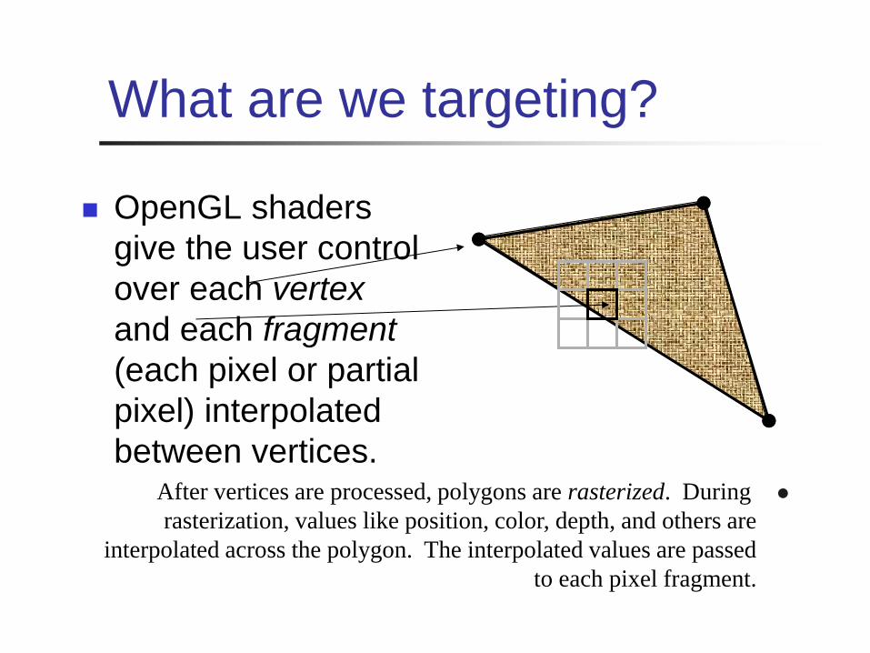
OpenGL shaders
give the user control
over each vertex
and each fragment
(each pixel or partial
pixel) interpolated
between vertices. After vertices are processed, polygons are rasterized. During
rasterization, values like position, color, depth, and others are
interpolated across the polygon. The interpolated values are passed
to each pixel fragment.

What can you override? Per vertex: Vertex transformation
Normal transformation and normalization
Texture coordinate generation
Texture coordinate transformation
Lighting
Color material application
Per fragment (pixel): Operations on
interpolated values
Texture access
Texture application
Fog
Color summation
Optionally: Pixel zoom
Scale and bias
Color table lookup
Convolution

Think parallel
Shaders are compiled from within your code They used to be written in assembler
Today they’re written in high-level languages ()
They execute on the GPU
GPUs typically have multiple processing units
That means that multiple shaders execute in parallel!
At last, we’re moving away from the purely-linear flow of early “C” programming models…

What’re we talking here?
There are several popular languages for
describing shaders, such as:
HLSL, the High Level Shading Language
Author: Microsoft
DirectX 8+
Cg
Author: nvidia
GLSL, the OpenGL Shading Language
Author: the Khronos Group, a self-sponsored
group of industry affiliates (ATI, 3DLabs, etc)


OpenGL programmable
processors
Figure 2.1, p. 39, OpenGL Shading Language, Second Edition, Randi Rost,
Addison Wesley, 2006. Digital image scanned by Google Books.

What happens when you
install a shader?
All the fixed functionality (see slide six) is overridden.
It’s up to you to replace it! You’ll have to transform each vertex into viewing
coordinates manually.
You’ll have to light each vertex manually.
You’ll have to apply the current interpolated color to each fragment manually.
The installed shader replaces all OpenGL fixed functionality for all renders until you remove it.

Shader gallery II
Above: Kevin Boulanger (PhD thesis,
“Real-Time Realistic Rendering of Nature
Scenes with Dynamic Lighting”, 2005)
Above: Ben Cloward (“Car paint shader”)

Shader sample one – ambient
lighting // Vertex Shader
void main() {
gl_Position =
gl_ModelViewProjectionMatrix * gl_Vertex;
}
// Fragment Shader
void main() {
gl_FragColor = vec4(0.2, 0.6, 0.8, 1);
}

Shader sample one – ambient
lighting

Shader sample one – ambient
lighting Notice the C-style syntax
void main() { … }
The vertex shader uses two standard inputs, gl_Vertex and the model-view-projection matrix; and one standard output, gl_Position.
The line gl_Position = gl_ModelViewProjectionMatrix * gl_Vertex;
applies the model-view-projection matrix to calculate the correct vertex position in perspective coordinates.
The fragment shader applies basic ambient lighting, setting its one standard output, gl_FragColor, to a fixed value.

Shader sample two – diffuse
lighting // Vertex Shader
varying vec3 Norm;
varying vec3 ToLight;
void main()
{
gl_Position =
gl_ModelViewProjectionMatrix * gl_Vertex;
Norm =
gl_NormalMatrix * gl_Normal;
ToLight = vec3(
gl_LightSource[0].position - (gl_ModelViewMatrix *
gl_Vertex));
}
// Fragment Shader
varying vec3 Norm;
varying vec3 ToLight;
void main()
{
const vec3 DiffuseColor = vec3(0.2, 0.6, 0.8);
float diff = clamp(dot(normalize(Norm), normalize(ToLight)), 0.0, 1.0);
gl_FragColor = vec4(DiffuseColor * diff, 1.0);
}

Shader sample two – diffuse
lighting

Shader sample two – diffuse
lighting
This examples uses varying parameters to
pass info from the vertex shader to the
fragment shader.
The varying parameters Norm and ToLight are
automatically linearly interpolated between vertices
across every polygon.
This represents the normal at that exact point on the
surface.
The exact diffuse illumination is calculated from the
local normal.
This is the Phong shading technique (usually seen for
specular highlights) applied to diffuse lighting.

Shader sample two – diffuse
lighting
Notice the different matrix transforms used in this example: gl_Position = gl_ModelViewProjectionMatrix *
gl_Vertex;
Norm = gl_NormalMatrix * gl_Normal;
ToLight = vec3(gl_LightSource[0].position - (gl_ModelViewMatrix * gl_Vertex));
The gl_ModelViewProjectionMatrix transforms a vertex from local coordinates to perspective coordinates for display, whereas the gl_ModelViewMatrix transforms a point from local coordinates to eye coordinates. We use eye coordinates because lights are (usually) defined in eye coordinates.
The gl_NormalMatrix transforms a normal from local coordinates to eye coordinates; it holds the inverse of the transpose of the upper 3x3 submatrix of the model-view transform.

GLSL – design goals GLSL was designed with the following in mind:
Work well with OpenGL Shaders should be optional extras, not required.
Fit into the design model of “set the state first, then render the data in the context of the state”
Support upcoming flexibility
Be hardware-independent The GLSL folks, as a broad consortium, are far more invested
in hardware-independence than, say, nvidia.
That said, they’ve only kinda nailed it: I get different compiler behavior and different crash-handling between my high-end home nVidia chip and my laptop Intel x3100.
Support inherent parallelization
Keep it streamlined, small and simple
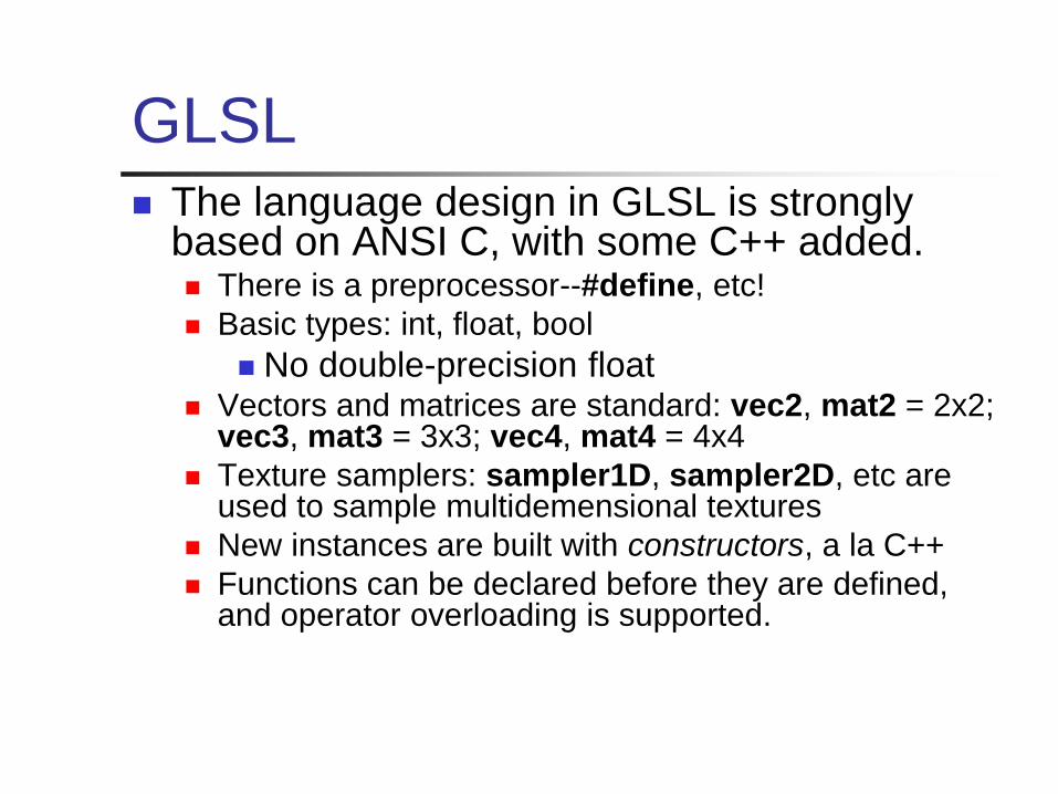
GLSL The language design in GLSL is strongly
based on ANSI C, with some C++ added. There is a preprocessor--#define, etc!
Basic types: int, float, bool
No double-precision float Vectors and matrices are standard: vec2, mat2 = 2x2;
vec3, mat3 = 3x3; vec4, mat4 = 4x4
Texture samplers: sampler1D, sampler2D, etc are used to sample multidemensional textures
New instances are built with constructors, a la C++
Functions can be declared before they are defined, and operator overloading is supported.

GLSL Some differences from C/C++:
No pointers, strings, chars; no unions, enums; no bytes, shorts, longs; no unsigned. No switch() statements.
There is no implicit casting (type promotion):
float foo = 1;
fails because you can’t implicitly cast int to float.
Explicit type casts are done by constructor:
vec3 foo = vec3(1.0, 2.0, 3.0);
vec2 bar = vec2(foo); // Drops foo.z
Function parameters are labeled as in (default), out, or inout.
Functions are called by value-return, meaning that values are copied into and out of parameters at the start and end of calls.
Program
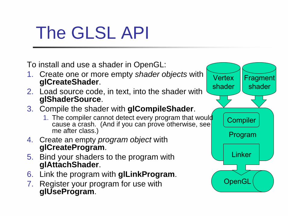
The GLSL API
To install and use a shader in OpenGL:
1. Create one or more empty shader objects with glCreateShader.
2. Load source code, in text, into the shader with glShaderSource.
3. Compile the shader with glCompileShader. 1. The compiler cannot detect every program that would
cause a crash. (And if you can prove otherwise, see me after class.)
4. Create an empty program object with glCreateProgram.
5. Bind your shaders to the program with glAttachShader.
6. Link the program with glLinkProgram.
7. Register your program for use with glUseProgram.
Vertex
shader
Fragment
shader
Compiler
OpenGL
Linker

Shader sample three – Gooch
shading
Image source: “A
Non-Photorealistic
Lighting Model For
Automatic Technical
Illustration”, Gooch,
Gooch, Shirley and
Cohen (1998).
Compare the Gooch
shader, above, to the
Phong shader (right).
Gooch shading is not a shader technique per se.
It was designed by Amy and Bruce Gooch to replace photorealistic lighting with a lighting model that highlights structural and contextual data.
• They use the diffuse term of the conventional lighting equation to choose a map between ‘cool’ and ‘warm’ colors.
• This is in contrast to conventional illumination where diffuse lighting simply scales the underlying surface color.
• This, combined with edge-highlighting through a second renderer pass, creates models which look more like engineering schematic diagrams.
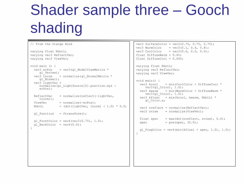
Shader sample three – Gooch
shading // From the Orange Book
varying float NdotL;
varying vec3 ReflectVec;
varying vec3 ViewVec;
void main () {
vec3 ecPos = vec3(gl_ModelViewMatrix * gl_Vertex);
vec3 tnorm = normalize(gl_NormalMatrix * gl_Normal);
vec3 lightVec = normalize(gl_LightSource[0].position.xyz - ecPos);
ReflectVec = normalize(reflect(-lightVec, tnorm));
ViewVec = normalize(-ecPos);
NdotL = (dot(lightVec, tnorm) + 1.0) * 0.5;
gl_Position = ftransform();
gl_FrontColor = vec4(vec3(0.75), 1.0);
gl_BackColor = vec4(0.0);
}
vec3 SurfaceColor = vec3(0.75, 0.75, 0.75);
vec3 WarmColor = vec3(0.1, 0.4, 0.8);
vec3 CoolColor = vec3(0.6, 0.0, 0.0);
float DiffuseWarm = 0.45;
float DiffuseCool = 0.045;
varying float NdotL;
varying vec3 ReflectVec;
varying vec3 ViewVec;
void main() {
vec3 kcool = min(CoolColor + DiffuseCool * vec3(gl_Color), 1.0);
vec3 kwarm = min(WarmColor + DiffuseWarm * vec3(gl_Color), 1.0);
vec3 kfinal = mix(kcool, kwarm, NdotL) * gl_Color.a;
vec3 nreflect = normalize(ReflectVec);
vec3 nview = normalize(ViewVec);
float spec = max(dot(nreflect, nview), 0.0);
spec = pow(spec, 32.0);
gl_FragColor = vec4(min(kfinal + spec, 1.0), 1.0);
}

Shader sample three – Gooch
shading

Shader sample three – Gooch
shading In the vertex shader source, notice the use of the built-in ability
to distinguish front faces from back faces:
gl_FrontColor = vec4(vec3(0.75), 1.0);
gl_BackColor = vec4(0.0);
This supports distinguishing front faces (which should be shaded smoothly) from the edges of back faces (which will be drawn in heavy black.)
In the fragment shader source, this is used to choose the weighted diffuse color by clipping with the a component:
vec3 kfinal = mix(kcool, kwarm, NdotL) * gl_Color.a;
Here mix() is a GLSL method which returns the linear interpolation between kcool and kwarm. The weighting factor (‘t’ in the interpolation) is NdotL, the diffuse lighting value.

Halflife 1 vs. Halflife 2

http://www.daionet.gr.jp/~masa/rthdribl/ind
ex.html

What is Cg?
Cg is a high level shader language
Made by NVIDIA, but supports other GPUs
Programmer writes in a language similar to
C
Cg compiler produces hardware-specific
optimized assembly code

The Vertex Shader
Program executed once per vertex
Takes per-vertex input such as position,
normal, color, light position, etc.
Determines per-vertex data such as
position, color, depth, etc.
But can do more!

The Vertex Shader

A Vertex Program
struct VertexInput {
float4 position : POSITION;
float3 normal : NORMAL;
}
void NormalShade( VertexInput input,
out float4 outPosition : POSITION,
out float3 outColor : COLOR,
const uniform float4x4 modelViewProjMatrix)
{
outPosition = mul(modelViewProjMatrix, input.position);
outColor = abs(input.normal);
}
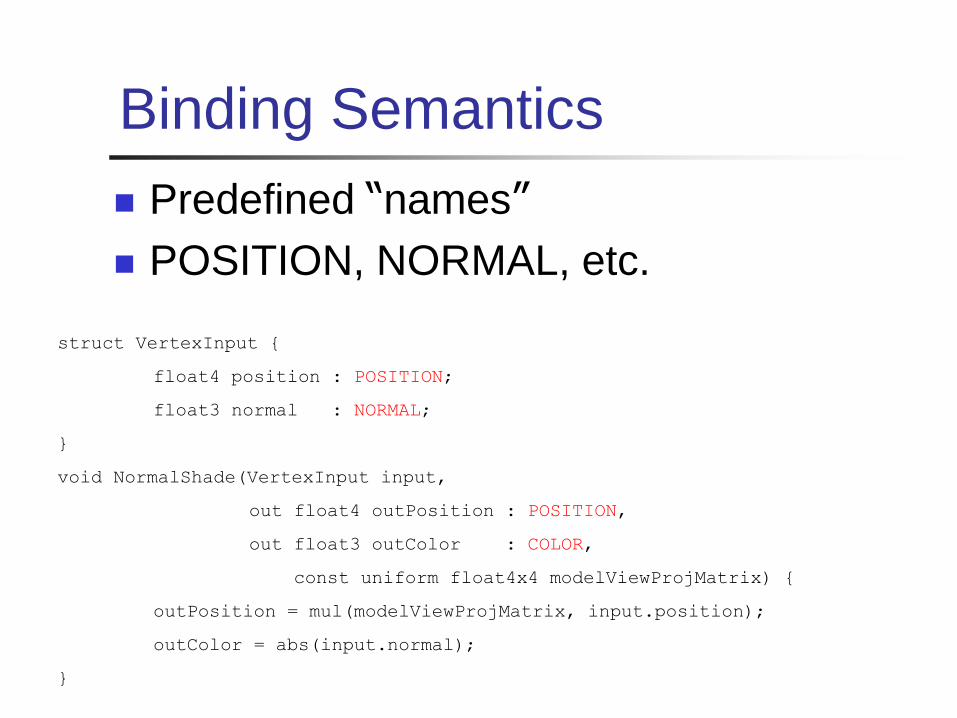
Binding Semantics
Predefined “names”
POSITION, NORMAL, etc.
struct VertexInput {
float4 position : POSITION;
float3 normal : NORMAL;
}
void NormalShade(VertexInput input,
out float4 outPosition : POSITION,
out float3 outColor : COLOR,
const uniform float4x4 modelViewProjMatrix) {
outPosition = mul(modelViewProjMatrix, input.position);
outColor = abs(input.normal);
}

Vertex Shader: Input
Varying parameters
Color, normal, texture coordinates, etc.
Data specified for each element
glBegin(GL_TRIANGLES);
glColor3f(1.0f, 0.0f, 0.0f);
glNormal3f(0.0f, 1.0f, 0.0f);
glVertex3f(1.0f, 1.0f, 1.0f);
//...
glEnd();
void Shade(float3 color : COLOR,
float3 normal : NORMAL,
float3 position : POSITION,...)
{
//...
}
OpenGL CG Vertex Program

Vertex Shader: Input
Uniform Parameters
Data that remains constant over each element
Parameter shadowing
cgSetParameter3f(kdParam, 0.3f,
0.2f, 0.6f)
glBegin(GL_TRIANGLES);
//...
glEnd();
void Shade(..., const uniform float3 kd)
{
//...
}
OpenGL CG Vertex Program

Vertex Shader: Output
Output serves as varying input to fragments
“Custom data” usually output as texcoords
struct VertexInput {
float4 position : POSITION;
float3 normal : NORMAL;
}
void NormalShade(VertexInput input,
out float4 outPosition : POSITION,
out float3 outColor : COLOR,
const uniform float4x4 modelViewProjMatrix) {
outPosition = mul(modelViewProjMatrix, input.position);
outColor = abs(input.normal);
}

Types in Cg
Syntax similar to C
Basic types
int, float, half, fixed, bool
Vector/Matrix types
int4, float3, bool2, float4x4
Arrays
int a[3], float4x4 matrices[4][4]

Playing with types
Vector initialization and swizzling
float4 vec4 = float4(1, 1, 1, 0);
float3 vec3 = vec4.yzw;
float3 color = vec3.rgb;
float3 position = 1.xxx;

The Fragment Shader
Program executed once per rasterized
pixel.
Takes varying output from vertex
program.
Certain outputs, like TEXCOORD0
interpolated.
Determines final color, depth for pixel.

The Fragment Shader

A Fragment Program
float3 SinWave(float3 tex : TEXCOORD0) : COLOR {
return sin(tex.x);
}

A Fragment Program
void PerPixelLight(float3 position : TEXCOORD0,
float3 normal : TEXCOORD1,
const uniform float3 eye,
const uniform float3 light)
{
float3 L = normalize(light – position);
float3 V = normalize(eye – position);
outColor = computeRd(L, N) + computeRs(L, V, N);
}

Performance
Fragment Programs are Expensive!
Try to do as much as possible in vertex
programs.
Try to keep fragment programs small.
Note: not all hardware supports
fragments
Rhodes 453 has Quadro FX GPU’s,
which DO support fragment programs

Initializing Cg
Create a context CGcontext cgContext = CgGL.cgCreateContext();
Select and enable Profile int cgVertexProfile = CgGL.CG_PROFILE_VP20;
CgGL.cgGLEnableProfile(cgVertexProfile);
Create & Load program CGprogram cgVertexProgram =
CgGL.cgCreateProgramFromFile(cgContext,
CgGL.CG_SOURCE, "Normal.cg", cgVertexProfile,
"Normal", null);
CgGL.cgGLLoadProgram(cgVertexProgram1);

Executing Cg
Get handles for parameters CGparameter mvpMatrix =
CgGL.cgGetNamedParameter(cgVertexProgram,
“ModelViewProjMatrix”);
Set parameters CgGL.cgGLSetStateMatrixParameter( mvpMatrix,
CgGL.CG_GL_MODELVIEW_PROJECTION_MATRIX,
CgGL.CG_GL_MATRIX_IDENTITY)
Bind program CgGL.CgGLBindProgram(cgVertexProgram);
Rendering
glBegin()…

Cg in Action: Normal Shader
First demo: using 1 vertex shader to
shade a cube based on its normal
Look at Normal.cg

Normal.cg
struct VertexInput {
float4 position : POSITION;
float3 normal : NORMAL;
};
struct VertexOutput {
float4 position : POSITION;
float3 color : COLOR0;
};
VertexOutput Normal(const VertexInput input,
const uniform float4x4 ModelViewProjMatrix) {
VertexOutput output;
output.position = mul(ModelViewProjMatrix, input.position);
output.color = (input.normal+1)/2;
return output;
}

Vertex.java: declarations
protected CGcontext cgContext;
protected int cgVertexProfile;
protected static CGprogram cgVertexProgram;
protected static CGparameter cgModelViewProjMatrix;

Vertex.java: initializations cgContext = CgGL.cgCreateContext();
cgVertexProfile = CgGL.CG_PROFILE_VP20;
CgGL.cgGLEnableProfile( cgVertexProfile);
cgVertexProgram = CgGL.cgCreateProgramFromFile( cgContext, CgGL.CG_SOURCE, "Normal.cg", cgVertexProfile, "Normal", null);
CgGL.cgGLLoadProgram(cgVertexProgram);
cgModelViewProjMatrix = CgGL.cgGetNamedParameter( cgVertexProgram, "ModelViewProjMatrix");

Vertex.java: Display loop
CgGL.cgGLBindProgram(cgVertexProgram);
CgGL.cgGLSetStateMatrixParameter(
cgModelViewProjMatrix,
CgGL.CG_GL_MODELVIEW_PROJECTION_MATRIX,
CgGL.CG_GL_MATRIX_IDENTITY);

More than 1 Vertex Program
Can use different vertex (fragment) programs for
different geometry!
Initialize programs as you would normally
1 context, 1 vertex profile, many programs, many loads,
etc.
In display loop, bind appropriate VP before
gl_Begin() … gl_End().
To use another VP, simply bind to it before the next
gl_Begin() … gl_End().

TwoVertex.java
Code very similar to Vertex.java
We load the pastel normal shader for the front and back faces, then load the bright normal shader for the rest of the cube
Note that we needed to gl_End() after the first 2 faces, then bind our next VP, then gl_Begin(GL_QUADS) again

SinWave.cg
float3 SinWave(float3 tex : TEXCOORD0) : COLOR {
return (sin(sin(23*tex.x*tex.y)-10*tex.y)+1)/2;
}
This shader is just using the texture coordinates, and
some math.
Like position and normal, these are made available by
OpenGL automatically
But if SinWave needed other parameters, we would obtain
and modify them as usual.
Fragment.java: declaration,
init
Very similar to Vertex, except with all
“vertex”es replaced with “fragment”s
We make sure to specify the texture
coordinates for the corners of each face
Texture coords are interpolated across
polygons, so fragment programs can use
them readily
Lambertian
Vertex program finds the normal and
light vectors in world space, outputting
those as COLOR0, COLOR1
Fragment program gets interpolated
normal, light vector for each pixel and
calculates lighting
Lambertian.java
Does standard declare, init:
1 context, 2 profiles (create, enable), 2
programs (create, load)
Gets, sets all necessary variables for both
programs
In display loop, bind both VP and FP
That’s it!

Some Tips
Check for errors!
CgErrorException.checkCgError();
Debug output in shaders
Normals, incident directions, different
terms in BRDFs, etc.
Can compile .cg programs
cgc –profile vp20 –entry (function name)
Program.cg

Resources
NVIDIA Cg: http://developer.nvidia.com/page/cg_main.html
Cg User Manual: http://developer.nvidia.com/object/cg_users_manual.html
Also in Cg Toolkit folder
http://www.cgshaders.org

