sh0(06dfrxvwlf kim et al. a new method to determine the ... · jin-ho choy, seong-gu kang,...
TRANSCRIPT

IOP Conference Series: Materials Science and Engineering
PAPER • OPEN ACCESS
Open-circuit sensitivity model based on empiricalparameters for a capacitive-type MEMS acousticsensorTo cite this article: Jaewoo Lee et al 2016 IOP Conf. Ser.: Mater. Sci. Eng. 108 012044
View the article online for updates and enhancements.
Related contentOpen-Circuit Voltage Improvement inInGaAs/InP Heterojunction Solar CellsChoul-Young Kim, Jung-Ho Cha, JaehoKim et al.
-
A study on measuring the electromagneticparameters of chiral materialsGuocai Sun, Kailun Yao, Zuli Liu et al.
-
A New Method to Determine the OxygenContent of YBa2Cu3O7-: Open-CircuitVoltage MeasurementJin-Ho Choy, Seong-Gu Kang, Dong-HoonKim et al.
-
This content was downloaded from IP address 54.70.40.11 on 24/10/2017 at 20:15

Open-circuit sensitivity model based on empirical parameters for a capacitive-type MEMS acoustic sensor
Jaewoo Lee1, 2, J.H. Jeon1, C.H. Je1, S.Q. Lee1, W.S. Yang1, and S.-G. Lee2 1Nano Sensor Lab, Electronics and Telecommunications Research Institute (ETRI), Republic of Korea
2Department of Electrical Engineering, Korea Advanced Institute of Science and Technology (KAIST), Republic of Korea
E-mail: [email protected] and [email protected] Abstract. An empirical-based open-circuit sensitivity model for a capacitive-type MEMS acoustic sensor is presented. To intuitively evaluate the characteristic of the open-circuit sensitivity, the empirical-based model is proposed and analysed by using a lumped spring-mass model and a pad test sample without a parallel plate capacitor for the parasitic capacitance. The model is composed of three different parameter groups: empirical, theoretical, and mixed data. The empirical residual stress from the measured pull-in voltage of 16.7 V and the measured surface topology of the diaphragm were extracted as +13 MPa, resulting in the effective spring constant of 110.9 N/m. The parasitic capacitance for two probing pads including the substrate part was 0.25 pF. Furthermore, to verify the proposed model, the modelled open-circuit sensitivity was compared with the measured value. The MEMS acoustic sensor had an open-circuit sensitivity of -43.0 dBV/Pa at 1 kHz with a bias of 10 V, while the modelled open-circuit sensitivity was -42.9 dBV/Pa, which showed good agreement in the range from 100 Hz to 18 kHz. This validates the empirical-based open-circuit sensitivity model for designing capacitive-type MEMS acoustic sensors.
1. Introduction MEMS microphones based on capacitive-type acoustic sensors compatible with CMOS processes have been rapidly replacing electret condenser microphones (ECMs) in the market of communication systems, especially smart phones, due to their competitive cost and technology. Recently, their application range has been expanded to a variety of monolithic integrated circuits, such as digital MEMS microphone modules and beam-forming modules, because they have monolithic integrated capability with ROIC. As a result, various design issues and fabrication methods related to capacitive-type MEMS acoustic sensors have been reported based on surface and bulk micromachining [1]-[8]. On the other hand, to investigate the characteristics of the MEMS acoustic sensors, an analogous equivalent circuit model has been applied in sensor modules [2], [6], [9]-[12]. Generally, the behaviour of acoustic-electro transducers has been modelled with lumped parameters. However, in spite of theoretically complicated analysis or finite-element method (FEM) simulation, it may be difficult to model some parameters, such as the effective residual spring constant in a diaphragm and parasitic capacitance for a MEMS sensor chip, owing to their inherently non-separability from an intrinsic part. In this paper, an empirical-based model of open-circuit sensitivity at a low frequency for a capacitive-type MEMS acoustic sensor is proposed and investigated. Each parameter was modelled
IC-MAST2015 IOP PublishingIOP Conf. Series: Materials Science and Engineering 108 (2016) 012044 doi:10.1088/1757-899X/108/1/012044
Content from this work may be used under the terms of the Creative Commons Attribution 3.0 licence. Any further distributionof this work must maintain attribution to the author(s) and the title of the work, journal citation and DOI.
Published under licence by IOP Publishing Ltd 1

through an extracted method based on empirical measurement, a theoretical method, or a mixed method of the two. In particular, both the residual stress and the parasitic capacitance are critical for determining the open-circuit sensitivity. To verify the proposed model, the modelled open-circuit sensitivity was compared with the measured sensitivity using an evaluation board for a packaged MEMS acoustic sensor.
2. Empirical based open-circuit sensitivity model
2.1. Lumped spring-mass model Figure 1 shows a schematic diagram of a conventional lumped spring-mass model for a capacitive-type acoustic sensor with a circular diaphragm. In this model, the movable plate is assumed to act like a piston without any difference between the centre point and an edge of the moving plate, when a uniform force is applied to the diaphragm.
Figure 1. Schematic diaphragm of a conventional lumped spring-mass model for a capacitive-type acoustic sensor with a circular diaphragm
Generally, from the large deflection theory, linearized restoring force (Fres) from a uniform force is expressed by
, (1)
where D is the flexural rigidity, a is the diaphragm radius, σ0 is the residual stress, h is the diaphragm thickness, and z is the axis direction in a cylindrical coordinate. In addition, the electrical force (Fele) between two electrodes is described as
, (2)
where g0 is the height of the air gap, Vb is the bias voltage, and the permittivity of vacuum. Thus, at an equilibrium condition equal to
Vb
spring
moving plate fixed plate
uniform force
gb
uniform force
Z
g0z
a0
0
r
𝐹!"# ≈ !64𝜋𝐷𝑎! + 4𝜋𝜎!ℎ! ∙ 𝑧
𝐹!"! = −𝑉!!
2𝜀!𝜋𝑎!
(𝑔! − 𝑧)!
IC-MAST2015 IOP PublishingIOP Conf. Series: Materials Science and Engineering 108 (2016) 012044 doi:10.1088/1757-899X/108/1/012044
2

, (3)
the pull-in voltage can be determined by
. (4)
From equation (4), it is obvious that the effective residual stress (σeff) can be extracted from both the pull-in voltage and the air gap between two electrodes. If its value is more than +5 MPa, the effective residual stress plays an essential role on the spring constant of a diaphragm, resulting in dominant impact on open-circuit sensitivity.
2.2. Each parameter extraction As shown in figure 2, parameters of open-circuit sensitivity at a low frequency for a capacitive-type acoustic sensor are divided into three parts: empirical, theoretical, and mixed data group. Among the empirical data, the residual stress (σ0) of the diaphragm must be extracted from the measured values due to its strong dependence on the specific structure of the sensor itself. In addition, it is not a simple task to extract the parasitic capacitance (Cpar) from the measured total capacitance owing to the non-linear substrate effect. Thus, on the basis of the empirical data, σ0 and Cpar must be determined to reflect some practical impact on open-circuit sensitivity at a low frequency. The modelling process based on empirical data is described in figure 3.
Figure 2. Three parameter groups of open-circuit sensitivity at a low frequency for a capacitive-type MEMS acoustic sensor
air-gap at bias (gb) residual stress (s0)pull-in voltage (VP) parasitic capacitance (CP)
open-circuit sensitivity(at a low frequency)
Empirical data
effective spring constant (keff)Mixed data
intrinsic capacitance (Cin)effective area (Aeff)
Theoretical data
𝐹!"# = 𝐹!"! 𝑎𝑡 𝑧 = 𝑔!/3
𝑉! = !827 !
64𝜋𝐷𝑎! + 4𝜋𝜎!""ℎ!
𝑔!!
𝜀!𝜋𝑎!
IC-MAST2015 IOP PublishingIOP Conf. Series: Materials Science and Engineering 108 (2016) 012044 doi:10.1088/1757-899X/108/1/012044
3
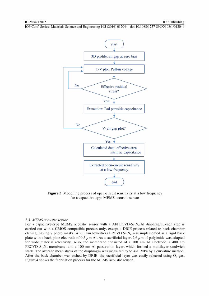
Figure 3. Modelling process of open-circuit sensitivity at a low frequency for a capacitive-type MEMS acoustic sensor
2.3. MEMS acoustic sensor For a capacitive-type MEMS acoustic sensor with a Al/PECVD-Si3N4/Al diaphragm, each step is carried out with a CMOS compatible process only, except a DRIE process related to back chamber etching, having 7 photo masks. A 2.0 µm low-stress LPCVD Si3N4 was implemented as a rigid back plate with a back plate electrode of 0.5 µm Al. As a sacrificial layer, 2.6 µm of polyimide was adapted for wide material selectivity. Also, the membrane consisted of a 100 nm Al electrode, a 400 nm PECVD Si3N4 membrane, and a 100 nm Al passivation layer, which formed a multilayer sandwich stack. The average mean stress of the diaphragm was measured to be +20 MPa by a curvature method. After the back chamber was etched by DRIE, the sacrificial layer was easily released using O2 gas. Figure 4 shows the fabrication process for the MEMS acoustic sensor.
Effective residual stress?
start
3D profile: air gap at zero bias
C-V plot: Pull-in voltage
Extracted open-circuit sensitivityat a low frequency
Yes
No
Extraction: Pad parasitic capacitance
V- air gap plot? No
Yes
end
Calculated data: effective area intrinsic capacitance
IC-MAST2015 IOP PublishingIOP Conf. Series: Materials Science and Engineering 108 (2016) 012044 doi:10.1088/1757-899X/108/1/012044
4

Figure 4. SEM images for the fabricated MEMS acoustic sensor with an Al/PECVD-Si3N4/Al diaphragm
2.4. Residual stress and Parasitic capacitance To extract the residual stress, the pull-in volatage and surface profile of the diaphragm were measured as shown in figure 5. From the measured pull-in voltage of 16.7 V and the height of air gap of 2.6 um, the effective residual stress was extracted by using equation (4). Here, σeff was determined to be +13 MPa, showing a difference of +7 MPa from the average mean stress. Thus, it is noted that σeff must be evaluated by using the practical value rather than the mean stress by the curvature method.
(a)
(b)
Figure 5. Surface topology of the diaphragm (a) and pull-in characteristic (b)
for the MEMS acoustic sensor
Φ = 650 um
Back-plate electrode
Back-plate (LPCVD-Si3N4)Acoustic chamber
Diaphragm holes
Diaphragm (Al/PECVD-Si3N4/Al)
*bottom side
Diaphragm
Air gap height: 2.6 um
-3D surface profile
0 2 4 6 8 10 12 14 16 181.0
1.5
2.0
2.5
3.0
3.5
Cm
ea (
pF)
Voltage ( V)
Pull-in voltage (VP) = 16.7 V
IC-MAST2015 IOP PublishingIOP Conf. Series: Materials Science and Engineering 108 (2016) 012044 doi:10.1088/1757-899X/108/1/012044
5

On the other hand, the relation of capacitance as a function of bias voltage can be applied in the extraction process of Cpar with an additional test sample: only a two-pad chip without an active parallel-plate capacitor. The extracted Cpar from the test sample was 0.25 pF. Also, the measured total capacitance (Cmea) at a zero bais and the cable paracitic capacitance (Ccab) were 1.43 pF and 0.05 pF, respectively. Thus, the intrincic capacitance (Cin) can be extracted as 1.13 pF by using
. (5)
In addtion to Cpar, the model process of separating Cin from Cmea is critical because both Cin and Cpar are applied to model the open-circuit sensitivity.
2.5. Open-circuit sensitivity When a bias voltage (Vb) is forced in the sensor, the open-circuit sensitivity at a low frequency can be expressed as
, (6) where gb is the height of the air gap at the bias voltage (Vb), Cb is the intrinsic capacitance at the bias voltage, Aeff is the effective capacitor area excluding the etching hole area, and keff is the effective spring constant containing the effective resisual stress. Here, Aeff and keff were 2.33 × 10⁻⁷ m2 and 110.9 N/m, respectively. As a result, when Vb was 10 V, S0 was modelled as -42.9 dBV/Pa at 1 kHz, where gb, Cb, Cpar were 2.45 um, 1.2 pF, and 0.25 pF. The design and modelled parameters are shown in Table. 1.
Table 1. Design and modelled parameters.
Parameters Values Diaphragm radius (r) 325 µm Diaphragm thickness (h) 0.6 µm Flexural rigidity (D) 4.78 × 10⁻⁹ N-m Effective residual stress (σeff) +13 MPa Pull-in voltage (Vp) 16.7 V Air-gap height (go) 2.6 µm Effective spring constant (keff) 110.9 N/m Effective area (Aeff) 2.33 × 10⁻⁷ m2
3. Results and Discussion To analyze the frequency characterisitic of an acoustic-electro transducer, an equivalent circuit model reflecting the influence of all of the acoustic, mechanical, and electrical signal domains [10] was used for open-circuit sensitivity (So). Figure 6 shows the structure-based model and its equivalent circuit for the dependency of open-circuit sensitivity on the frequency. In the steady-state condition, So is defined
𝐶!" = 𝐶!"# − 𝐶!"# − 𝐶!"#
𝑆! =𝑉!𝑔!𝐴!""𝑘!""
!𝐶!
𝐶! + 𝐶!"#!
IC-MAST2015 IOP PublishingIOP Conf. Series: Materials Science and Engineering 108 (2016) 012044 doi:10.1088/1757-899X/108/1/012044
6

as the transfer function of the output voltage as a function of the input pressure. Thus, it can be expressed [10] as
Figure 6. Schematic view for the MEMS acoustic sensor and an equivalent circuit for the open-circuit sensitivity
, (7)
where K1(w) and K2(w) are given by
, (8)
. (9)
As S0 is determined by the complicated interconnection among elements in three signal domains, the proposed equivalent circuit is suitable to accurately design and evaluate microphone performance.
Rr (ω) θa
Mr Md CdRgRh
Cbc
Pd
Ud
Fd Fe υe C0 Cp
i1:Aeff Г:1
P (ω)
Acoustic wave(bottom-inlet type)
Diaphragm (top assigned design) Air gap
hole
θa
P (ω)
MdCdCbc
Rg
Rh
Mr
Rr (ω)
Read-out IC
PCB
Metal lid
S0 (ω)
Vout (ω)
Vout (ω)
P (ω)
Vout (ω)
IC-MAST2015 IOP PublishingIOP Conf. Series: Materials Science and Engineering 108 (2016) 012044 doi:10.1088/1757-899X/108/1/012044
7

Figure 7. Images of the packaged MEMS acoustic sensor with ROIC Based on the equivalent circuit model shown in figure 6, each parameter was calculated or extracted by either theoretical calculation or empirical measurement. The modelled So was -42.9 dBV/Pa at 1 kHz at the bias voltage of 10 V, and the first resonance frequency was 67 kHz. Furthermore, to compare the modelled values with the measured values, the MEMS acoustic sensor was packaged with a read-out IC (ROIC). Figure 7 shows an integrated MEMS microphone module, where the PCB had an area of 3.4 mm × 2.8 mm, and the metal lid had the height of 0.6 mm. The measurement was performed in an 8.0 m × 8.0 m × 7.0 m anechoic chamber with a commercial analysis set (B&K) in the sweep range of 100 Hz to 18 kHz. Accordingly, the total measured sensitivity (Smea) of the packaged acoustic sensor was -42.0 dBV/Pa at 1 kHz (0 dB = 1 V/Pa), where the ROIC had 0.7 pF input capacitance, 10.0 V output bias, and 6 dB gain. Subsequently, So was extracted from Smea using
, (10)
where G is the gain of the ROIC, and Cin is the input capacitance of the ROIC.
Figure 8. Modelled and measured S0 as a function of frequency for the MEMS acoustic sensor
- Packaged MEMS microphone
Acoustic sensor Read-out IC
PCB area: 3.4 mm × 2.8 mm
Lid: 0.6 mm (h)
100 1000 10000 100000-60
-50
-40
-30
-20
Sens
itivi
ty (d
BV/
Pa)
Frequency (Hz)
measured S0modelled S0
measured S0 at 10 V = -43.0 dBV/Pa @ 1 kHz
modelled fr at 10 V = 67 kHz
IC-MAST2015 IOP PublishingIOP Conf. Series: Materials Science and Engineering 108 (2016) 012044 doi:10.1088/1757-899X/108/1/012044
8

From (10), So was extracted to be -43.0 dBV/Pa at 1 kHz with the bias point of 10.0 V, while the modelled open-circuit sensitivity was -42.9 dBV/Pa, as shown in figure 8. This validates the structure-based equivalent circuit modelling and the open-circuit sensitivity at a low frequency presented in the previous section. Table II summarizes the measured and modelled data of the proposed MEMS acoustic sensor.
Table 2. Measured and modelled data of the proposed MEMS acoustic sensor
Parameters Values Bias voltage (Vb) 10.0 V Aig-gab height at Vb (gb) 2.45 µm Intrinsic capacitance at Vb (Cb) 1.2 pF Parasitic capacitance (Cp) 0.25 pF Modelled open-circuit sensitivity at Vb (So-mod) -42.9 dBV/Pa Measured open-circuit sensitivity at Vb (So-med) -43.0 dBV/Pa ROIC input capacitance (Cin) 0.7 pF ROIC gain (G) 6 dB Measured total sensitivity at Vb (Smea) -42.0 dBV/Pa
4. Conclusions An empirical-based model of open-circuit sensitivity at a low frequency for a capacitive-type MEMS acoustic sensor was proposed. To model the open-circuit sensitivity, both the residual stress and the parasitic capacitance were extracted from empirical data because it is difficult to analytically obtain both of them due to their structure dependence. The residual stress was modelled from both the pull-in voltage and surface topology of the diaphragm, whereas the parasitic capacitance was determined from an additional test pattern. To evaluate the proposed empirical model, the modelled open-circuit sensitivity was compared with the measured sensitivity by using a packaged MEMS acoustic sensor. The modelled open-circuit sensitivity was in good agreement with the measured value in the range from DC to higher frequency, demonstrating the validity of the modelling.
5. References [1] J. Bergqvist and F. Rudolf, “A silicon condenser microphone using bond and etch-back
technology,” Sensor and Actuators A, vol. 45, pp. 115-124, 1994 [2] P. R. Scheeper, A. G. H. var der Donk, W. Olthuis, and P. Bergveld, “A review of silicon
microphones,” Sensor and Actuators A, vol. 44, pp. 1-11, 1994 [3] Q. Zou, Z. Li, and L. Liu, “Design and fabrication of silicon condenser microphone using
corrugated diaphragm technique,” IEEE J. Microelectromech. Syst., vol. 5, pp. 197-204, 1996 [4] A. Torkkeli, O. Rusanen, J. Saarilahti, H. Seppa, H. Sipola, and J. Hietanen, “Capacitive
microphone with low-stress polysilicon membrane and high-stress polysilicon backplate,” Sensor and Actuators A, vol. 85, pp. 116-123, 2000.
[5] J. W. Weigold, T. J. Brosnihan, J. Bergeron, and X. Zhang, “A MEMS condenser microphone for consumer applications,” IEEE MEMS 2006 Conf., Istanbul, Turkey, pp. 86-89, Jan. 2006
IC-MAST2015 IOP PublishingIOP Conf. Series: Materials Science and Engineering 108 (2016) 012044 doi:10.1088/1757-899X/108/1/012044
9

[6] M. Gato, Y. Iguchi, K. Ono, A. Ando, F. Takeshi, S. Matsunaga, Y. Ya- suno, K. Tanioka, and T. Tajima, “High-performance condenser microphone with single-crystalline silicon diaphragm and backplate,” IEEE Sens. J., vol. 7, pp. 4-10, Jan. 2007
[7] C.-K. Chan, W-C. Lai, M. Wu, M.-Y. Wang, and W. Fang, “Design and implementation of a capacitive-type microphone with rigid diaphragm and flexible spring using the two poly silicon micromachining processes,” IEEE Sens. J., vol. 11, pp. 2365-2371, Oct. 2011
[8] J. Lee, C. H. Je, J. H. Jeon, W. S. Yang, and J. Kim, “A surface micromachined MEMS acoustic sensor with back-plate anchors of 100 µm depth,” IEEE Sensor 2011 Conf., pp. 1978-1981, Oct. 2011
[9] J. Bergqvist, “Finite-element modelling and characterization of a silicon condenser microphone with a highly perforated backplate,” Sensor and Actuators A, vol. 39, pp. 191-200, 1993
[10] H. A C Tilmans, “Equivalent circuit representation of electromechanical transducers: I. lumped-parameter systems,” J. Micromech. Microeng., vol. 9, pp. 157-176. Mar. 1996
[11] W. J. Wang, R. M. Lin, Q. B. Zou, and X. X. Li, “Modeling and characterization of a silicon condenser microphone,” J. Micromech. Microeng., vol. 14, pp. 403-409. 2004
[12] M. Fuldner, A. Dehe, and R. Lerch, “Analytical analysis and finite element simulation of advanced membrane for silicon microphones,” IEEE Sens. J., Journal, vol. 5, pp. 857-863, Oct. 2005.
Acknowledgments This work was supported by Electronics and Telecommunications Research Institute (ETRI) grant funded by the Korea government (15ZB1500, Development of Environment & User Adaptable MEMS Microphone Solution).
IC-MAST2015 IOP PublishingIOP Conf. Series: Materials Science and Engineering 108 (2016) 012044 doi:10.1088/1757-899X/108/1/012044
10