sg1000 split third port telecommunications optical node ... · pdf filesg1000 split third port...
TRANSCRIPT

S G 1 0 0 0 S p l i t T h i r d P o r tT e l e c o m m u n i c a t i o n s O p t i c a l N o d e
I n s t a l l a t i o n a n d O p e r a t i o n M a n u a l
RF4
RF3
7
3
S T A R L I N E ®
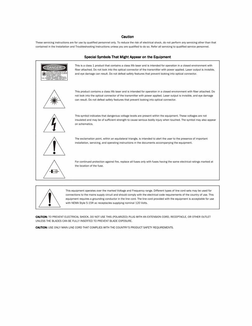
CautionCautionCautionCaution These servicing instructions are for use by qualified personnel only. To reduce the risk of electrical shock, do not perform any servicing other than that contained in the Installation and Troubleshooting Instructions unless you are qualified to do so. Refer all servicing to qualified service personnel.
Special Symbols That Might Appear on the EquipmentSpecial Symbols That Might Appear on the EquipmentSpecial Symbols That Might Appear on the EquipmentSpecial Symbols That Might Appear on the Equipment
INVISIBLE LASER RADIATION
PEAK POWER 5.0mWWAVELENGTH 1300nmCLASS IIIb LASER PRODUCTCHAPTER 1 SUBCHAPTER J
THIS PRODUCT COMPLIES WITH 21CFR
AVOID DIRECT EXPOSURE TO BEAM
DANGER
This is a class 1 product that contains a class IIIb laser and is intended for operation in a closed environment with fiber attached. Do not look into the optical connector of the transmitter with power applied. Laser output is invisible, and eye damage can result. Do not defeat safety features that prevent looking into optical connector.
This product contains a class IIIb laser and is intended for operation in a closed environment with fiber attached. Do not look into the optical connector of the transmitter with power applied. Laser output is invisible, and eye damage can result. Do not defeat safety features that prevent looking into optical connector.
This symbol indicates that dangerous voltage levels are present within the equipment. These voltages are not insulated and may be of sufficient strength to cause serious bodily injury when touched. The symbol may also appear on schematics.
The exclamation point, within an equilateral triangle, is intended to alert the user to the presence of important installation, servicing, and operating instructions in the documents accompanying the equipment.
For continued protection against fire, replace all fuses only with fuses having the same electrical ratings marked at the location of the fuse.
This equipment operates over the marked Voltage and Frequency range. Different types of line cord sets may be used for connections to the mains supply circuit and should comply with the electrical code requirements of the country of use. This equipment requires a grounding conductor in the line cord. The line cord provided with the equipment is acceptable for use with NEMA Style 5-15R ac receptacles supplying nominal 120 Volts.
CAUTION: CAUTION: CAUTION: CAUTION: TO PREVENT ELECTRICAL SHOCK, DO NOT USE THIS (POLARIZED) PLUG WITH AN EXTENSION CORD, RECEPTACLE, OR OTHER OUTLET UNLESS THE BLADES CAN BE FULLY INSERTED TO PREVENT BLADE EXPOSURE.
CAUTION: CAUTION: CAUTION: CAUTION: USE ONLY MAIN LINE CORD THAT COMPLIES WITH THE COUNTRY’S PRODUCT SAFETY REQUIREMENTS.

FCC ComplianFCC ComplianFCC ComplianFCC Compliancececece This equipment has been tested and found to comply with the limits for a Class A digital device, pursuant to Part 15 of the FCC Rules. These limits are designed to provide reasonable protection against harmful interference when the equipment is operated in a commercial environment. This equipment generates, uses, and can radiate radio frequency energy and, if not installed and used in accordance with the Installation Manual, may cause harmful interference to radio communications. Operation of this equipment in a residential area is likely to cause harmful interference in which case the user will be required to correct the interference at his/her own expense. Any changes or modifications not expressly approved by Motorola could void the user’s authority to operate this equipment under the rules and regulations of the FCC.
Canadian ComplianceCanadian ComplianceCanadian ComplianceCanadian Compliance This Class A digital apparatus meets all requirements of the Canadian Interference-Causing Equipment Regulations. Cet appareil numérique de la classe A respects toutes les exigences du Règlement sur le matériel brouilleur du Canada.
Declaration of ConformityDeclaration of ConformityDeclaration of ConformityDeclaration of Conformity
We Motorola, Inc. 101 Tournament Drive
Horsham, PA 19044, U.S.A.
declare under our sole responsibility that the
STARLINE® Model SG1000 Split Third Port
to which this declaration relates is in conformity with one or more of the following standards:
EMC StandardsEMC StandardsEMC StandardsEMC Standards
EN55022 EN55024 EN50083-2 CISPR-22 CISPR-24
Safety StandardsSafety StandardsSafety StandardsSafety Standards
EN60065 EN60825 EN60950 IEC 60950 + A1: 1992 + A2: 1993 + A3: 1995 + A4: 1996
following the provisions of the Directive(s) of the Council of the European Union:
EMC Directive 89/336/EEC Low Voltage Directive 73/23/EEC
Copyright © 2002 by Motorola, Inc.
All rights reserved. No part of this publication may be reproduced in any form or by any means or used to make any derivative work (such as translation, transformation or adaptation) without written permission from Motorola, Inc.
Motorola reserves the right to revise this publication and to make changes in content from time to time without obligation on the part of Motorola to provide notification of such revision or change. Motorola provides this guide without warranty of any kind, either implied or expressed, including, but not limited to, the implied warranties of merchantability and fitness for a particular purpose. Motorola may make improvements or changes in the product(s) described in this manual at any time.
IBM is a registered trademark of International Business Machines Corporation.
Windows is a registered trademark of Microsoft Corporation.
Motorola, the stylized M logo, and STARLINE are registered trademarks and LIFELINE is a trademark of Motorola, Inc. All other product or service marks are the property of their respective owners. © Motorola, Inc. 2002

SG1000 Split Third Port Installation and Operation Manual
Contents
Section 1 Introduction
Using This Manual............................................................................................................................................................................1-3 Related Documentation ...................................................................................................................................................................1-4 Document Conventions ...................................................................................................................................................................1-4 If You Need Help ...............................................................................................................................................................................1-4 Calling for Repairs............................................................................................................................................................................1-5
Section 2 Overview
Housing .............................................................................................................................................................................................2-2 Housing Lid ..............................................................................................................................................................................2-2 Mounting Holes........................................................................................................................................................................2-2 Port Locations..........................................................................................................................................................................2-2 Gaskets .....................................................................................................................................................................................2-3
Power Supply....................................................................................................................................................................................2-5 Network Monitoring..........................................................................................................................................................................2-6 Ingress Control .................................................................................................................................................................................2-6 Configuration ....................................................................................................................................................................................2-6 Forward RF Path...............................................................................................................................................................................2-8 Level Control...................................................................................................................................................................................2-10
Tilt Selection ..........................................................................................................................................................................2-10 Return Path .....................................................................................................................................................................................2-11
Optical Return Transmitters .................................................................................................................................................2-11
Section 3 Setup and Operation
Powering the Node...........................................................................................................................................................................3-1 60/90 Vac Supply .....................................................................................................................................................................3-1 220 Vac Supply ........................................................................................................................................................................3-5
Setting-Up the Forward Path ...........................................................................................................................................................3-8 Selecting the Gain Control......................................................................................................................................................3-9 Forward Path Padding...........................................................................................................................................................3-10 Selecting the Wavelength .....................................................................................................................................................3-11 Optical Power Test Point ......................................................................................................................................................3-12 Verifying RF Output Levels...................................................................................................................................................3-12 Output Passives.....................................................................................................................................................................3-12

ii Contents
SG1000 Split Third Port Installation and Operation Manual
Configuring the Return-Path......................................................................................................................................................... 3-14 Installing SG1000 Optical Modules .............................................................................................................................................. 3-15 Removing SG1000 Optical Modules............................................................................................................................................. 3-16 Ingress Control Option.................................................................................................................................................................. 3-17 Status Monitor Option ................................................................................................................................................................... 3-17 Cleaning the Optical Connectors ................................................................................................................................................. 3-18
Section 4 Installation
Pre-installation Procedures ............................................................................................................................................................ 4-1 Removing the Lid .................................................................................................................................................................... 4-1 Removing the E-pack.............................................................................................................................................................. 4-1
Installing the Node........................................................................................................................................................................... 4-2 Strand Wire Mounting............................................................................................................................................................. 4-2 Installing the E-pack ............................................................................................................................................................... 4-3 Splicing the Service Cable ..................................................................................................................................................... 4-3 Installing Pin-Type Connectors ............................................................................................................................................. 4-4 Installing the Coaxial Cables ................................................................................................................................................. 4-5 Installing the Fiber Cables ..................................................................................................................................................... 4-5 Closing the Housing ............................................................................................................................................................. 4-10
Appendix A Specifications
Optical ...............................................................................................................................................................................................A-1 Station RF .........................................................................................................................................................................................A-1 General..............................................................................................................................................................................................A-1 RF for the SG1-*/* Laser Transmitters ...........................................................................................................................................A-2 220 Vac Line Power Option.............................................................................................................................................................A-2
Appendix B Torque Specifications
Abbreviations and Acronyms
Figures Figure 1-1 SG1000 node—closed .................................................................................................................................................. 1-1 Figure 1-2 SG1000 node—open..................................................................................................................................................... 1-2 Figure 2-1 SG1000 housing dimensions — front and side view ................................................................................................ 2-2 Figure 2-2 Port locations................................................................................................................................................................ 2-3 Figure 2-3 Housing gaskets ........................................................................................................................................................... 2-4 Figure 2-4 SG1-PS power supply .................................................................................................................................................. 2-5

Contents iii
SG1000 Split Third Port Installation and Operation Manual
Figure 2-5 Configuration notation..................................................................................................................................................2-7 Figure 2-6 SG1000 – dual-output, optical-return block diagram ................................................................................................2-9 Figure 2-7 Relative level dB versus 750 MHz..............................................................................................................................2-10 Figure 2-8 Relative level dB versus 870 MHz..............................................................................................................................2-11 Figure 2-9 SG1000 optical transmitter block diagram ...............................................................................................................2-12 Figure 3-1 SG1000 60/90 Vac power supply .................................................................................................................................3-2 Figure 3-2 Fuse configuration........................................................................................................................................................3-3 Figure 3-3 Fuse locations ...............................................................................................................................................................3-4 Figure 3-4 SG1000 with 220 Vac power cord................................................................................................................................3-5 Figure 3-5 SG1000 amplifier cover with 220 Vac power option ..................................................................................................3-6 Figure 3-6 SG1-PS/220 installed in the SG1000............................................................................................................................3-7 Figure 3-7 RF chassis with cover...................................................................................................................................................3-8 Figure 3-8 RF chassis with cover removed ..................................................................................................................................3-8 Figure 3-9 Gain control jumper ......................................................................................................................................................3-9 Figure 3-10 Wavelength selection jumper ..................................................................................................................................3-11 Figure 3-11 MB-SP splitter............................................................................................................................................................3-13 Figure 3-12 MB-DC/* directional coupler.....................................................................................................................................3-13 Figure 3-13 SG1-DFBT optical transmitter ..................................................................................................................................3-14 Figure 4-1 Rear view of housing, strand clamps, and pedestal mounting holes......................................................................4-2 Figure 4-2 Service cable connection and compression fitting ...................................................................................................4-3 Figure 4-3 Center conductor length ..............................................................................................................................................4-4 Figure 4-4 Fiber tray and carriage..................................................................................................................................................4-6 Figure 4-5 Cable dressing with left port entry ..............................................................................................................................4-7 Figure 4-6 Cable dressing with right port entry ...........................................................................................................................4-8 Figure 4-7 Retracted fiber tray .......................................................................................................................................................4-9 Figure 4-8 Housing bolt tightening sequence ............................................................................................................................4-10
Tables Table 3-1 AC fuses ..........................................................................................................................................................................3-3 Table 3-2 SG1000 pad chart, silicon-hybrid, high-gain..............................................................................................................3-10 Table 3-3 SG1 receiver minimum output levels..........................................................................................................................3-12 Table 3-4 Ingress switch states....................................................................................................................................................3-17 Table 3-5 Common problems .......................................................................................................................................................3-18

SG1000 Split Third Port Installation and Operation Manual
Section 1 Introduction
Motorola’s® SG1000 telecommunications optical node with split third port performs lightwave-to-RF and RF-to-lightwave signal conversions in an optical transmission link. This product supports a wide variety of advanced hybrid-fiber/coaxial network topologies.
Product enhancements including the activation of Port 3 as a split, fully diplexed RF port are included in this manual.
As broadband communication systems continue to evolve, the demand increases for optical links that carry the signal further into the transport system. These systems require additional features and functionality such as digital compression and alternative access at significantly lower costs. Fully configured, the SG1000 supports these next-generation telecommunication networks. It also supports a variety of single and two-way broadband network applications such as broadcast video, interactive video, telephony, and data.
Figure 1-1 illustrates a closed SG1000 telecommunications optical node:
Figure 1-1 SG1000 node—closed

1-2 Introduction
SG1000 Split Third Port Installation and Operation Manual
Figure 1-2 illustrates an open SG1000 telecommunications optical node:
Figure 1-2 SG1000 node—open
PUSH
Base
Lid
SG1000Optical Transmitter
RETURNINPUT JXP
RETURN INPUTTEST POINT
ASSEMBLEDIN MEXICO
OPTICALPOWER
TEST POINT(1V/mW)
DANGER
O P T I C A LO U T P U T
ASSEMBLED IN MEXICO
SG1-
RTN INPUTP JXP
TP2/3 -20dB
TP2/3 -20dB
JXP 2/33
H
L
2
P O R T 1
P O R T 2
TP1 -20dB
TOTAL POWER
L
NOMINAL-5 dBmV
1 V / m W
JXP 1
MONITORSTATUS
RTN
MONITORSTATUS
JXP 1
JXP 2/3
H
L
FWD TP1 -20dB
S G 1 0 0 0O p t i c a l N o d e
INPUT JXP
ICS
ICS
P O R T 3
REFER TOMANUAL FORFUSE VALUES
CAUTION:CONTAINS PARTS
AND ASSEMBLIESSUSCEPTIBLE TO
DAMAGE BYELECTROSTATIC
DISCHARGE (ESD)
-20 dB
1 V / m W
OPTICALINPUT
FUSE 3
FUSE 1
FUSE 2
FTEC
NO USER SERVICABLEPARTS INSIDE
AC TEST POINT
24V 5V
SG1-PS
TESTPOINT
TESTPOINT
CAUTIONUSE CAUTION WHEN MAKING
INTERNAL ADJUSTMENTSWITH COVER REMOVED
VOLTAGES IN EXCESS OF300 VOLTS ARE PRESENTUNDER COVER AND MAY
BE PRESENT FOR SEVERALMINUTES AFTER POWER
IS REMOVEDSEE INSTALLATION MANUALFOR SERVICE
LO (60V )
H I (90V )

Introduction 1-3
SG1000 Split Third Port Installation and Operation Manual
Features include:
! 750 MHz or 870 MHz forward bandwidth option
! Built-in optical receiver
! Optional optical return transmitter
! Optional LIFELINE™ status monitoring
! Optional ingress switching capability through the LIFELINE status monitor
! One or two RF outputs with optional third port activation using MB-SP and MB-DC*
! Built-in thermal compensation
! 15 amp power passing
! Modular plug-in diplex filters and equalizers
! Support for low, standard, and high slope options
! 60/90 volt powering
Using This Manual The following sections provide information and instructions to install, configure, and operate the SG1000:
Section 1 Introduction provides a product description, related documentation, the technical helpline, and repair/return information.
Section 2 Overview describes the functions of the SG1000 and includes details regarding your options and their functions.
Section 3 Setup and Operation provides full configuration, setup of options, and bench testing procedures that are recommended prior to installation. It also provides information governing the applications required by your system.
Section 4 Installation provides instructions on how to install the SG1000.
Appendix A Specifications provides the technical specifications for the SG1000.
Appendix B Torque Specifications provides the appropriate torque specifications for the screws, clamps, connectors, and bolts used in the SG1000.
Abbreviations and Acronyms
The Abbreviations and Acronyms list contains the full spelling of the short forms used in this manual.

1-4 Introduction
SG1000 Split Third Port Installation and Operation Manual
Related Documentation Although these documents provide information that may be of interest to you, they are not required to install or operate the SG1000:
! LL-CU LIFELINE Control Unit Installation and Operation Manual
! LIFELINE for Windows® Site Preparation Guide
! LIFELINE for Windows Software Operations Manual
! Return Path Level Selection, Setup, and Alignment Procedure Reference Guide
Document Conventions Before you begin using the SG1000, familiarize yourself with the stylistic conventions used in this manual:
Bold type Indicates text that you must type exactly as it appears or indicates a default value
SMALL CAPS Denotes silk screening on the equipment, typically representing front- and rear-panel controls and input/output (I/O) connections, and LEDs
*(asterisk)
Indicates that several versions of the same model number exist and the information applies to all models; when the information applies to a specific model, the complete model number is given
Italic type Denotes a displayed variable, a variable that you must type, or is used for emphasis
If You Need Help If you need assistance while working with the SG1000, contact the Motorola Technical Response Center (TRC):
! Inside the U.S.A.: 1-888-944-HELP (1-888-944-4357)
! Outside the U.S.A.: 1-215-323-0044
! Online: http://www.motorola.com/broadband, click HTML/Modem Version, click Customer Support, then click Web Support.
The TRC is open from 8 AM to 7 PM Eastern Time, Monday through Friday and 10 AM to 6 PM Eastern Time, Saturday. When the TRC is closed, emergency service only is available on a call-back basis. Web Support offers a searchable solutions database, technical documentation, and low priority issue creation/tracking 24 hours per day, 7 days per week.

Introduction 1-5
SG1000 Split Third Port Installation and Operation Manual
Calling for Repairs If repair is necessary, call the Motorola Repair Facility at 1-800-642-0442 for a Return for Service Authorization (RSA) number before sending the unit. The RSA number must be prominently displayed on all equipment cartons. The Repair Facility is open from 7:00 AM to 4:00 PM Pacific Time, Monday through Friday.
When calling from outside the United States, use the appropriate international access code and then call 52-631-311-1100, to contact the Repair Facility.
When shipping equipment for repair, follow these steps:
1 Pack the unit securely.
2 Enclose a note describing the exact problem.
3 Enclose a copy of the invoice that verifies the warranty status.
4 Ship the unit PREPAID to the following address: Motorola BCS c/o Exel Attn: RSA #___________ 6908 East Century Park Dr. Tucson, AZ 85706

SG1000 Split Third Port Installation and Operation Manual
Section 2 Overview
Motorola’s STARLINE® SG1000 with split third port is the newest addition to the next generation of telecommunications optical nodes. It provides a low cost solution to support evolving fiber-deep networks. It meets the latest demands of a single and two-way broadband network application including broadcast video, telephony and data.
Configured with one optical receiver, two high-level RF outputs, and an optional return-path module, the node offers low-cost flexibility. Ingress switching through LIFELINE enables you to identify and isolate ingress problems and mitigate the effects. Modular design enables system upgrades and component replacement with minimal system interruption.
Additional features include:
! SC/APC or FC/APC connectors
! Pedestal or strand mount housing
! Gas tube or Fast Trigger Electronic Crowbar (FTEC) surge protection
! Optional Silicon or Gallium Arsenide (GaAs) output hybrid
! Optional isolated distributed feedback (DFBT/* and DFBT3/*), isolated Fabry-Perot (IFPT/*), enhanced isolated Fabry-Perot (EIFPT/*), or non-isolated (FPT/*) optical-return transmitters
! User-friendly fiber management
! Standard gain models

2-2 Overview
SG1000 Split Third Port Installation and Operation Manual
Housing The SG1000 optical node is furnished in an aluminum housing that protects the electronics from weather and dissipates internally generated heat.
Figure 2-1 illustrates the SG1000 housing:
Figure 2-1 SG1000 housing dimensions — front and side view
9.80
16.13Release tab
5.68
6 2 4
87
513
RF1
RF4
RF2
RF3
Coaxial cable connections to the housing are made with conventional 5/8 inch - 24-thread, stinger-type connectors. For strand mounting, two clamps are located at the top of the housing and are secured with 5/16 inch – 18-thread stainless steel bolts.
Housing Lid A spring-release tab is located on the hinge side of the lower housing half as illustrated in Figure 2-1. It prevents sideways motion of the lid on the hinge pin when the node is open. You can remove the lid without tools by pressing down on the release tab and sliding the lid to the left.
Mounting Holes Two threaded holes, separated by 9.96 inches center-to-center, are located in the back of the housing on the horizontal center-line as illustrated in Figure 4-1. You can use these holes and the bolts from the strand clamps for pedestal mounting. These holes are threaded to a depth of 0.55 inches.
Port Locations The housing provides five cable connections (three RF ports and two optical-fiber ports). All ports are protected by factory-inserted threaded plugs or plastic cap plugs. Discard these plugs when you install the cable connectors.

Overview 2-3
SG1000 Split Third Port Installation and Operation Manual
Figure 2-2 illustrates a front and end view of the closed housing and the port locations:
Figure 2-2 Port locations
Fiberinput
Fiberinput
RF3
Base BaseLid
RF2
RF1
6 2 4
87
513
RF1
RF4
RF2
RF3
Gaskets Each housing is equipped with a woven-wire RF gasket and a silicone-rubber weather gasket to provide a seal between the housing base and lid. These gaskets provide efficient ground continuity, RF shielding, and weather protection. Both gaskets must be in place and in good condition to ensure proper operation and protection of the station. The weather gasket should be lightly coated with silicone grease each time the node is opened. Replace this gasket if it becomes damaged or deformed.

2-4 Overview
SG1000 Split Third Port Installation and Operation Manual
Figure 2-3 illustrates the housing gaskets:
Figure 2-3 Housing gaskets
PUSH
SG1000Optical Transmitter
RETURNINPUT JXP
RETURN INPUTTEST POINT
ASSEMBLEDIN MEXICO
OPTICALPOWER
TEST POINT(1V/mW)
DANGER
O P T I C A LO U T P U T
ASSEMBLED IN MEXICO
SG1-
RTN INPUTP JXP
TP2/3 -20dB
TP2/3 -20dB
JXP 2/33
H
L
2
P O R T 1
P O R T 2
TP1 -20dB
TOTAL POWER
L
NOMINAL-5 dBmV
1 V / m W
JXP 1
MONITORSTATUS
RTN
MONITOR
STATUS
JXP 1
JXP 2/3
H
L
FWD TP1 -20dB
S G 1 0 0 0O p t i c a l N o d e
INPUT JXP
ICS
ICS
P O R T 3
REFER TOMANUAL FOR
FUSE VALUES
CAUTION:CONTAINS PARTSAND ASSEMBLIESSUSCEPTIBLE TO
DAMAGE BYELECTROSTATIC
DISCHARGE (ESD)
-20 dB
1 V / m W
OPTICALINPUT
FUSE 3
FUSE 1
FUSE 2
FTEC
NO USER SERVICABLEPARTS INSIDE
AC TEST POINT
24V 5V
SG1-PS
TESTPOINT
TESTPOINT
CAUTIONUSE CAUTION WHEN MAKING
INTERNAL ADJUSTMENTSWITH COVER REMOVED
VOLTAGES IN EXCESS OF300 VOLTS ARE PRESENTUNDER COVER AND MAY
BE PRESENT FOR SEVERALMINUTES AFTER POWER
IS REMOVEDSEE INSTALLATION MANUALFOR SERVICE
LO (60V )
H I (90V)
RF gasket(woven wire)
Weather gasket(silicone rubber)

Overview 2-5
SG1000 Split Third Port Installation and Operation Manual
Power Supply The SG1000 power supply (SG1-PS) is located in the housing lid to optimize heat transfer and to balance the thermal load between the base and the lid. An umbilical cord connects the SG1-PS to the housing base.
A flexible power-distribution design enables you to power the node from any of the three RF ports. Using fuses and shunts, you can configure the node to distribute power to the remaining active ports.
The power supply includes a heavy-duty, gas discharge tube surge protector located on the amplifier module. You can replace this surge protector with the optional FTEC surge protector. The FTEC triggers at approximately 230 Vac and presents a short circuit to the line during periods of overvoltage. After the ac input voltage returns to normal, the FTEC returns to its open circuit state. This provides the node with a level of protection against surge currents on the ac line.
Figure 2-4 illustrates the SG1-PS power supply:
Figure 2-4 SG1-PS power supply
NO USER SERVICABLEPARTS INSIDE
AC TEST POINT
24V 5V
SG1-PS
TESTPOINT
TESTPOINT
CAUTIONUSE CAUTION WHEN MAKING
INTERNAL ADJUSTMENTSWITH COVER REMOVED
VOLTAGES IN EXCESS OF300 VOLTS ARE PRESENTUNDER COVER AND MAY
BE PRESENT FOR SEVERALMINUTES AFTER POWER
IS REMOVEDSEE INSTALLATION MANUALFOR SERVICE
LO (60V )
H I (90V)
SG1-PSpower supply Transponder
60/90 Vselector

2-6 Overview
SG1000 Split Third Port Installation and Operation Manual
Network Monitoring The optional LIFELINE status monitoring system (LL-SG1) enables you to monitor the SG1000 from a headend or remote location. The LL-SG1 transponder is located in the lid, as illustrated in Figure 2-4, and is connected to the electronics package (E-pack) with an umbilical cord.
The LIFELINE network monitoring system includes:
LL-CU control units These units are connected to the system at the headend and interrogate each SG1000 field transponder with FM outbound and inbound transmissions. You can select a variety of outbound and inbound frequencies depending on the system configuration. The control unit reports this information to the status-monitor computer.
Status-monitor computer and software
Includes an IBM®-compatible computer that is connected to the control unit LL-CU through an RS-232 link. LIFELINE software enables you to view measurements taken by the transponders.
LL-SG1-* field transponders
Installed in individual SG1000 nodes, this unit interfaces with the LL-CU at the headend. It reports such parameters as: forward amplifier dc current draw and gain control voltage, ac supply voltage, optical power at receiver input and transmitter output, +24 V supply voltage and current, forward-path RF output level, and management and control of RF ingress switching and tamper status.
Ingress Control Two ingress control switches (ICS) provide return-path signal attenuation in the SG1000. Attenuation is accomplished using the LIFELINE status-monitoring transponder (LL-SG1) located in the lid next to the power supply. The status monitor transponder controls the ICS through digital control lines. Using a downstream command through the LIFELINE status-monitoring system, the return paths can be attenuated through the SG1000 by 6 dB or by 40 dB. By adjusting the ingress switch from the headend, you can isolate the ingress source. After you isolate an ingress source to the last possible node, you can shut the return path off at that location to limit the impact of the ingress on the remainder of the network.
Configuration To accommodate unique system criteria, the SG1000 is shipped as a configured product. Hundreds of variations are available with configurations designed to address varied system requirements including:
Optional features include:
! Fiber optic service cable
! Surge protection
! Chromate or epoxy housing finish
! SC/APC or FC/APC optical connectors
! Optical return transmitter
! Ingress Switching
! Network monitoring

Overview 2-7
SG1000 Split Third Port Installation and Operation Manual
The shipped configuration is noted in a label on the RF chassis cover illustrated in Figure 3-4.
Figure 2-5 illustrates the configuration notation:
Figure 2-5 Configuration notation
Key7587
Bandpass750 MHz870 MHz
KeyT
Third PortThird port available
KeyN*
ReservedReserved for future use
KeyABLSH
Tilt6 dB8 dB10 dB12.5 dB14 dB
KeyNBDHIJ
Return Path ConfigurationNo transmitterSG1-FPT/* (0.4 mW)SG1-DFBT/* (1.0 mW)SG1-DFBT3/* (2.0 mW)SG1-DFBT/* w/ 0 dB padSG1-EIFPT/* (1.0 mW)
K SG1-DFBT3/* w/0dB Pad
KeySJAKEM
Bandpass Split5-40 MHz/52-870 MHz5-55 MHz/70-870 MHz5-65 MHz/85-870 MHz5-42 MHz/54-870 MHz5-30 MHz/47-870 MHz5-80 MHz/108-870 MHz
KeyAB
RF Output Config1 Output2 Output
CD
1 Output High Gain2 Output High Gain
KeyEN
ErgonomicsErgonomic unitNon-ergonomic
KeyNC
Service CableNone4 fiber service cable
KeySG
TechnologySiliconGaAs
KeyNF
Surge ProtectionSurge protectorFTEC-BTA crowbar
KeySF
ConnectorizationSC/APCFC/APC
Key Status MonitorN No status monitor
H LL-AM-HMS
ABCD
LL-SG1/52-5.5LL-SG1/*75-5.5LL-SG1/*52-6.5LL-SG1/*89-14.5
KeyNC
Housing FinishNoneChromate
E E-pack only
KeyNSA
Ingress SwitchNo ingress switchesIngress switches0 dB pad
KeyNAB
Power SupplyStandard90 volt jumper selected220 volt power supply
KeyAN
Special25 amp fusesStandard
SG1 75 S S B S F S B N N N N N N T N*N* N* E
* Reserved for future use
The current catalog may contain information not presented in this configuration diagram.

2-8 Overview
SG1000 Split Third Port Installation and Operation Manual
Forward RF Path The receiver module is integrated within the E-pack. The receiver’s integrated optical hybrid photo-detector improves RF performance over the entire 47 through 870 MHz passband. An optical-power monitor circuit provides assessment of the fiber link status. The receiver module is fully compatible with the status-monitor transponder enabling remote monitoring of key module and link performance parameters.
A positive intrinsic-negative (PIN) attenuator, driven by an integrated thermal control circuit, provides temperature compensation for the forward RF path.
An SG1000 distribution response correction (1DR) plug-in board follows the PIN attenuator and is selected during configuration according to the 750 or 870 MHz requirements. It provides a portion of the required slope characteristic. Plug-in forward equalizers located before each output hybrid provide the remainder of the slope characteristic.
Each output stage uses a Silicon or GaAs power-doubled output hybrid. The diplex filters are selected during configuration according to the preferred frequency split. You can change the filters to accommodate different splits. You will also need to change the RPLPF in the return transmitter.
The SG1000 can be factory configured for one or two outputs. If you require only one output, the second RF output is not populated on the E-pack. To field upgrade a single-output node to a dual-output node, contact your Motorola sales representative for the appropriate kit.
Port 1 is a dedicated node output in the SG1000. Where you install the furnished MB-JMP jumper determines whether the other path feeds Port 2 or Port 3. The model MB-SP splitter and model MB-DC/* directional coupler are available separately and provide an output at Port 2 and Port 3. The MB-SP provides equal output levels, while the MB-DC/* provides one high-level port and one low-level port. The high-level signal is routed to Port 2 or Port 3 and is based on the MB-DC/*s orientation during installation. Figure 2-1 illustrates the port numbers identified on the amplifier cover.
For each port, the status monitor transponder input is taken from the port one, forward RF output, test point. A directional coupler is used to ensure that the operation of the RF output test point is unaffected by the presence or absence of the status monitor. A new MCX connector has been added before the return-path transmitter that enables the status monitor to inject its output signal.
Overview 2-9
SG1000 Split Third Port Installation and Operation Manual
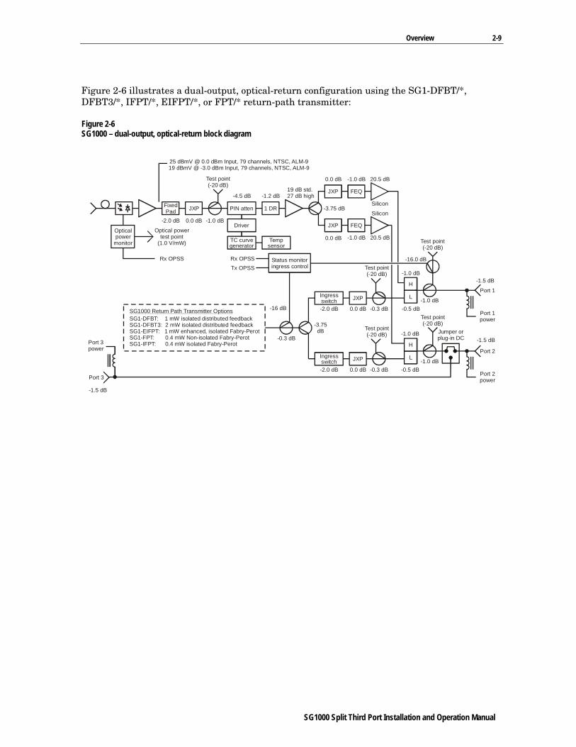
Figure 2-6 illustrates a dual-output, optical-return configuration using the SG1-DFBT/*, DFBT3/*, IFPT/*, EIFPT/*, or FPT/* return-path transmitter:
Figure 2-6 SG1000 – dual-output, optical-return block diagram
25 dBmV @ 0.0 dBm Input, 79 channels, NTSC, ALM-919 dBmV @ -3.0 dBm Input, 79 channels, NTSC, ALM-9
Test point(-20 dB)
Optical powertest point
(1.0 V/mW)
-2.0 dB 0.0 dB -1.0 dB
-4.5 dB -1.2 dB 27 dB high19 dB std.
FixedPad 1 DRJXP
Opticalpower
monitor
Rx OPSS
-1.5 dB
PIN atten
TC curvegenerator
Tempsensor
Driver
Port 3
Port 3power
0.0 dB
0.0 dB
-3.75 dB
-1.0 dB
-1.0 dB
Silicon
Silicon
20.5 dB
20.5 dB
JXP FEQ
JXP FEQ
-1.5 dB
-1.5 dB
Rx OPSSTx OPSS
Test point(-20 dB)
Jumper orplug-in DC
Test point(-20 dB)
-1.0 dB
-0.3 dB
-16 dB-1.0 dB
-16.0 dB
-0.5 dB
-1.0 dB
-0.5 dB
-1.0 dB
Port 2power
Port 1power
Port 2
Port 1H
L
L
Status monitoringress control
-3.75dB
0.0 dB
0.0 dB
JXP
JXP
-2.0 dB
-2.0 dB
Ingressswitch
Ingressswitch
Test point(-20 dB)
Test point(-20 dB)
-0.3 dB
-0.3 dB
H
SG1000 Return Path Transmitter OptionsSG1-DFBT: 1 mW isolated distributed feedbackSG1-DFBT3: 2 mW isolated distributed feedbackSG1-EIFPT: 1 mW enhanced, isolated Fabry-PerotSG1-FPT: 0.4 mW Non-isolated Fabry-PerotSG1-IFPT: 0.4 mW isolated Fabry-Perot

2-10 Overview
SG1000 Split Third Port Installation and Operation Manual
Level Control The gain of hybrid IC amplifiers varies with temperature. The integrated thermal control circuit senses temperature and works to offset the gain variation in the hybrid IC amplifier by signaling needed changes to the RF PIN attenuator.
In addition, changes in system channel loading and/or splices in the fiber link can change the level of the received signal.
Tilt Selection To use the tilt selection charts, first determine the system operating bandwidth, either 750 MHz or 870 MHz. Next, determine the preferred system channel load. Use the corresponding bandwidth and channel loading chart (Figure 2-7 or 2-8) to determine the preferred tilt.
Figure 2-7 illustrates the relative level dB chart for 750 MHz bandwidth:
Figure 2-7 Relative level dB versus 750 MHz
-350 150 250 350 450 550 650 750
-1-2
0123456789
1011121314
Frequency, MHzDigital loading is 6 dB below analog levels
Rel
ativ
e le
vel,
dB
SG1000 750 MHz Slope Chart
14 dB
12.5 dB
10 dB
8 dB
6 dB

Overview 2-11
SG1000 Split Third Port Installation and Operation Manual
Figure 2-8 illustrates the relative level dB chart for 870 MHz bandwidth:
Figure 2-8 Relative level dB versus 870 MHz
-350 150 250 350 450 550 750650 870
-1-2
0123456789
1011121314
Frequency, MHzDigital loading is 6 dB below analog levels
Rel
ativ
e le
vel,
dB
SG1000 870 MHz Slope Chart
14 dB
12.5 dB
10 dB
8 dB
6 dB
Return Path To meet present and future return-path requirements, you can configure the SG1000 with one of five optical transmitters to accommodate data and video signal transmission.
Optical Return Transmitters The five optical return transmitters and their features include:
SG1-IFPT/* Uses an uncooled, Fabry-Perot laser operating at 400 µW. Carries a full 35 MHz of digital data or up to two video channels.
SG1-EIFPT/* Uses an uncooled, Fabry-Perot laser operating at 1 mW. Carries a full 35 MHz of digital data or up to two video channels.
SG1-DFBT/* Uses an uncooled, isolated DFB laser operating at 1 mW for improved link performance. Carries a full 35 MHz of digital data or up to two video channels.
SG1-DFBT3/* Uses an uncooled, isolated DFB laser operating at 2 mW for improved link performance. Carries a full 35 MHz of digital data or up to two video channels.
SG1-FPT/* Uses a non-isolated Fabry-Perot laser and is intended for data transmission only.
All transmitters include thermal compensation to minimize the change in received optical and RF signal level at the headend as the node temperature varies. To enable remote monitoring of key performance parameters, all transmitters are fully compatible with the status-monitor transponder.

2-12 Overview
SG1000 Split Third Port Installation and Operation Manual
Figure 2-9 illustrates a functional block diagram of the SG1000 optical transmitter:
Figure 2-9 SG1000 optical transmitter block diagram
RFinput
Opticaloutput
Optical powersense signal(1.0 V/mW)
Optical powertest point
(1.0 V/mW)
LPF JXP JXP Laser
PINdriver
13.4 dBmVnominal
TC curvegenerator
Temperaturesensor
Fixedpad
PINattenuatorPreamp Hybrid
Return levelset-up pad
OMI alignment pad(factory-set)
Lasermatching
APCcircuit
Return levelmonitor test point(-5 dBmV nominal)

SG1000 Split Third Port Installation and Operation Manual
Section 3 Setup and Operation
This section provides information governing the use of various options and applications required by your system.
Before you install the SG1000, it must be setup to meet the power and configuration requirements for the node location. Bench setup is recommended to ensure proper functioning of all components and to simplify field installation.
Powering the Node You can conveniently power the node by applying 60 Vac or 90 Vac to any of the three RF ports. You can configure the node to distribute power from any port to either or both of the remaining ports. You can also select the 220 Vac powering option.
60/90 Vac Supply For optimal operation, the ac input from the feederline to the power supply must be between 44 V and 90 V root mean square (rms) with a line frequency of 50 Hz or 60 Hz. The waveshape of the input voltage must be quasi-squarewave. A precision output regulator protects against overcurrent and short circuits thus providing a precise output voltage.
You can power the SG1000 from 60 Vac or 90 Vac system supplies. The unit is shipped from the factory set for 60 Vac (LO). To change the power-supply setting, use a Phillips head screwdriver or one-quarter inch nut driver to remove the ten screws that secure the cover. Remove the cover. If your system uses 90 Vac powering, reposition the suitcase jumper on the dc power supply to the 90 V (HI) position to optimize the supply turn-on voltage for the higher input range.
No damage results if you do not change the jumper. In a 90 V system, changing the jumper ensures that the dc supply does not turn on until the proper input voltage level is reached. This prevents excessive loading of the system power supply during turn on after a power-off situation.
Test points are provided for the ac, 24 Vdc, and 5 Vdc supplies. A green LED indicates powering of the dc circuits.
3-2 Setup and Operation
SG1000 Split Third Port Installation and Operation Manual
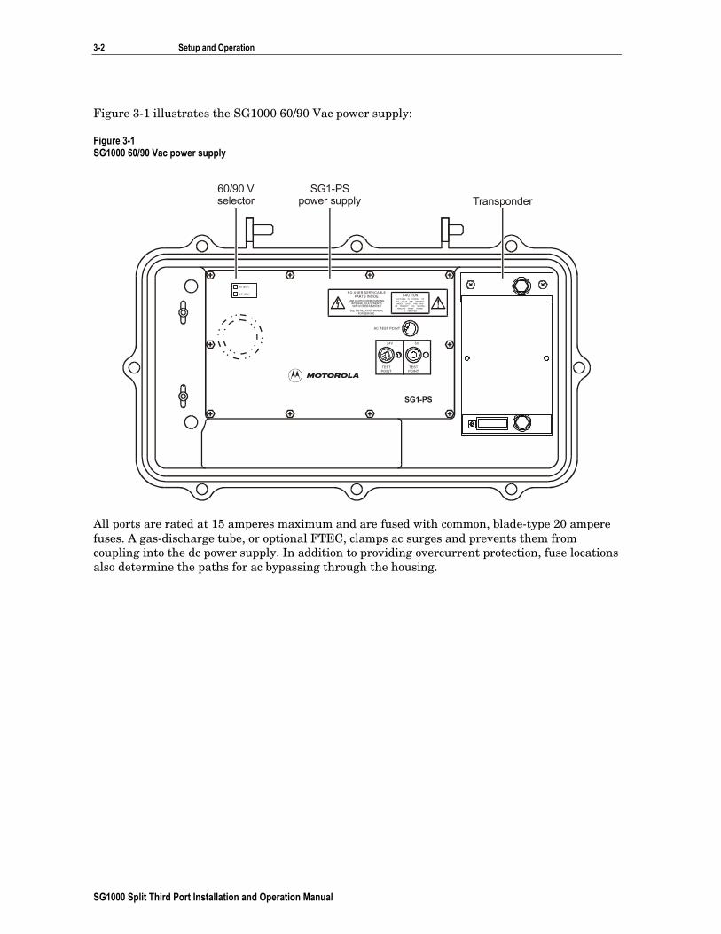
Figure 3-1 illustrates the SG1000 60/90 Vac power supply:
Figure 3-1 SG1000 60/90 Vac power supply
NO USER SERVICABLEPARTS INSIDE
AC TEST POINT
24V 5V
SG1-PS
TESTPOINT
TESTPOINT
CAUTIONUSE CAUTION WHEN MAKING
INTERNAL ADJUSTMENTSWITH COVER REMOVED
VOLTAGES IN EXCESS OF300 VOLTS ARE PRESENTUNDER COVER AND MAY
BE PRESENT FOR SEVERALMINUTES AFTER POWER
IS REMOVEDSEE INSTALLATION MANUALFOR SERVICE
LO (60V )
H I (90V)
SG1-PSpower supply Transponder
60/90 Vselector
All ports are rated at 15 amperes maximum and are fused with common, blade-type 20 ampere fuses. A gas-discharge tube, or optional FTEC, clamps ac surges and prevents them from coupling into the dc power supply. In addition to providing overcurrent protection, fuse locations also determine the paths for ac bypassing through the housing.
Setup and Operation 3-3
SG1000 Split Third Port Installation and Operation Manual
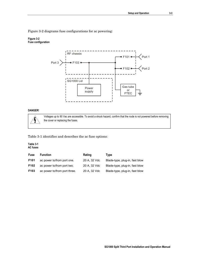
Figure 3-2 diagrams fuse configurations for ac powering:
Figure 3-2 Fuse configuration
Powersupply
SG1000 Lid
Port 3 F103
RF chassisF101
F102
Port 1
Port 2
Gas tubeor
FTEC
DANGER!
Voltages up to 90 Vac are accessible. To avoid a shock hazard, confirm that the node is not powered before removing the cover or replacing the fuses.
Table 3-1 identifies and describes the ac fuse options:
Table 3-1 AC fuses
Fuse Function Rating Type F101 ac power to/from port one. 20 A, 32 Vdc Blade-type, plug-in, fast blow
F102 ac power to/from port two. 20 A, 32 Vdc Blade-type, plug-in, fast blow
F103 ac power to/from port three. 20 A, 32 Vdc Blade-type, plug-in, fast blow

3-4 Setup and Operation
SG1000 Split Third Port Installation and Operation Manual
Figure 3-3 illustrates the RF chassis cover and fuse locations for the 60/90 Vac power supply:
Figure 3-3 Fuse locations
SG1000Optical Transmitter
RETURNINPUT JXP
RETURN INPUTTEST POINT
ASSEMBLEDIN MEXICO
OPTICALPOWER
TEST POINT(1V/mW)
D A NG E R
O P T I C A LO U T P U T
ASSEMBLED IN MEXICO
SG1-
RTN INPUTP JXP
TP2/3 -20dB
TP2/3 -20dB
JXP 2/33
H
L
2
P O R T 1
P O R T 2
TP1 -20dB
TOTAL POWER
L
NOMINAL-5 dBmV
1 V / m W
JXP 1
MONITORSTATUS
RTN
MONITORSTATUS
JXP 1
JXP 2/3
H
L
FWD TP1 -20dB
S G 1 0 0 0O p t i c a l N o d e
IN PUT JXP
IC S
IC S
P O R T 3
REFER TOMANUAL FORFUSE VALUES
CAUTION:CONTAINS PARTSAND ASSEMBLIESSUSCEPTIBLE TO
DAMAGE BYELECTROSTATIC
DISCHARGE (ESD)
-20 dB
1 V / m W
OPTICALINPUT
FUSE 3
FUSE 1
FUSE 2
FTEC
Port 1fuse FTEC
Port 2fuse
Port 3fuse

Setup and Operation 3-5
SG1000 Split Third Port Installation and Operation Manual
220 Vac Supply The SG1000 is now available with a 220 Vac line power option. This node is designed for indoor use only and has a reduced operating temperature.
Do not use this power supply in conjunction with a coaxial network-powered system.
The SG1-PS/220 power supply is also located in the housing lid to optimize heat transfer and balance the thermal load between the base and the lid. An internal umbilical cord connects the SG1-PS/220 to the housing base. The ac power cord is terminated with an IEC 320 male connector and enters the housing lid through a nylon strain relief.
Lightning protection and fusing are also provided; however, there are no internal user-serviceable parts.
Figure 3-4 illustrates a closed SG1000 node and 220 Vac power cord:
Figure 3-4 SG1000 with 220 Vac power cord
Bench setup is recommended and requires a 220 Vac power source with a female IEC 320 connector to interface with the line cord.

3-6 Setup and Operation
SG1000 Split Third Port Installation and Operation Manual
The SG1-PS/220 equipped node has no power passing capability, and the fuses on the main board have been removed at the factory.
Figure 3-5 illustrates the RF amplifier cover on the SG1000 with the 220 Vac power option:
Figure 3-5 SG1000 amplifier cover with 220 Vac power option
SG1000Optical Transmitter
RETURNINPUT JXP
RETURN INPUTTEST POINT
ASSEMBLEDIN MEXICO
OPTICALPOWER
TEST POINT(1V/mW)
D A NG E R
OPTICALOUTPUT
ASSEMBLED IN MEXICO
SG1-
RTN INPUTP JXP
TP2/3 -20dB
TP2/3 -20dB
JXP 2/33
H
L
2
P O R T 1
P O R T 2
TP1 -20dB
TOTAL POWER
L
NOMINAL-5 dBmV
1 V / m W
JXP 1
MONITORSTATUS
RTN
MONITORSTATUS
JXP 1
JXP 2/3
H
L
FWD TP1 -20dB
S G 1 0 0 0Apartment House
O p t i c a l N o d e
INPUT JXP
IC S
IC S
P O R T 3
WARNING:FOR INDOOR
USE ONLY
CAUTION:CONTAINS PARTSAND ASSEMBLIESSUSCEPTIBLE TO
DAMAGE BYELECTROSTATIC
DISCHARGE (ESD)
-20 dB
1 V / m W
OPTICALINPUT
For operation, the ac input from the line cord to the power supply must be between 176 Vac and 264 Vac and a frequency of 47 Hz to 63 Hz sinusoidal wave. A precision output regulator protects against overcurrent and short circuits thus providing precise output voltages of +24 and +5 Vdc.
There are no test points or LEDs on the SG1-PS/220 to indicate powering of the dc circuits. The yellow wire from the power supply cover is used for factory tests only. Do not disconnect the screw or lug under any circumstances.

Setup and Operation 3-7
SG1000 Split Third Port Installation and Operation Manual
Figure 3-6 illustrates the SG1-PS/220 installed in the lid of the SG1000:
Figure 3-6 SG1-PS/220 installed in the SG1000
SG1-PS/220power supply
DC outputcable
AC linecord Lid
DO NOT REMOVE COVER. NO USER SERVIC ABLE PARTSIN SIDE. FOR PROPER INSTALLATION AN D OPERATIN G
PROCED URES REFER TO INSTALLATION MAN UAL.
WARNING:
CAUTION
RISK OF ELECTRIC SHOC KDO NOT OPEN
SG1-PS/220V
AC INPUT176-264 VAC; 0.8A
47-63 Hz

3-8 Setup and Operation
SG1000 Split Third Port Installation and Operation Manual
Setting-Up the Forward Path The following subsections provide information for specific forward-path functions.
For your convenience, Figures 3-7 and 3-8 show the RF chassis installed in the SG1000 housing base.
Figure 3-7 illustrates the RF chassis with the cover on as it provides a functional diagram and indicates the location of all major components:
Figure 3-7 RF chassis with cover
SG1000Optical Transmitter
RETURNINPUT JXP
RETURN INPUTTEST POINT
ASSEMBLEDIN MEXICO
OPTICALPOWER
TEST POINT(1V/mW)
D A NG E R
O P T I C A LO U T P U T
ASSEMBLED IN MEXICO
SG1-
RTN INPUTP JXP
TP2/3 -20dB
TP2/3 -20dB
JXP 2/33
H
L
2
P O R T 1
P O R T 2
TP1 -20dB
TOTAL POWER
L
NO MINAL-5 dBmV
1 V / m W
JXP 1
MONITO RSTATUS
RTN
MONITORSTATUS
JXP 1
JXP 2/3
H
L
FWD TP1 -20dB
S G 1 0 0 0O p t i c a l N o d e
INPUT JXP
IC S
IC S
P O R T 3
REFER TOMANUAL FORFUSE VALUES
CAUTION:CONTAINS PARTSAND ASSEMBLIESSUSCEPTIBLE TO
DAMAGE BYELECTROSTATIC
DISCHARGE (ESD)
-20 dB
1 V / m W
OPTICALINPUT
FUSE 3
FUSE 1
FUSE 2
FTEC
Prying nubs
Configuration labelReturn TP
port 1
Return TPports 2, 3
Forward TPport 1
Forward TPports 2, 3
Figure 3-8 illustrates the RF chassis with the cover removed for a better view of the board components:
Figure 3-8 RF chassis with cover removed
Interstageequalizer
Inputpad
Ingressswitches
OutputpadRF1
OutputpadRF2
Outputequalizer
RF1
Outputequalizer
RF2
SG1000Optical Transmitter
RETURNINPUT JXP
RETURN INPUTTEST POINT
ASSEMBLEDIN MEXICO
OPTICALPOWER
TEST POINT(1V/mW)
D A NG E R

Setup and Operation 3-9
SG1000 Split Third Port Installation and Operation Manual
Before you begin:
Test the input power using an optical power meter to ensure that expected levels are present.
Refer to Section 4, “Installation,” Installing the Fiber Cables to verify that required connections have been made to the bulkhead fitting.
Selecting the Gain Control Thermal control circuitry provides thermal gain control that compensates for changes in gain caused by temperature variations. The available gain reserve is factory-set for optimum operation and is not field adjustable. You can however, set an internal jumper to disable thermal gain control. This enables you to operate the station at full gain for applications that do not require gain stabilization.
The gain-control jumper is factory-set to enable thermal gain control. If you want to reset the jumper:
1 Loosen the chassis cover screws and remove the cover.
2 Position the jumper on the appropriate pins for the preferred gain control mode.
3 Replace the chassis cover and torque the screws to 15 to 17 in-lbs. Be careful that you do not pinch the fibers between the chassis cover and chassis.
Figure 3-9 illustrates the gain control jumper and its location:
Figure 3-9 Gain control jumper
FULL TC
13J104
SG1000Optical Transmitter
RETURNINPUT JXP
RETURN INPUTTEST POINT
ASSEMBLEDIN MEXICO
OPTICALPOWER
TEST POINT(1V/mW)
D A NG E R

3-10 Setup and Operation
SG1000 Split Third Port Installation and Operation Manual
Forward Path Padding The pad values, presented in Table 3-2, serve as a starting-point reference for typical installations. These charts are prepared specifically for 77 channel systems with an upper-band edge of 750 MHz or 870 MHz. For a 110 channel system, reduce the value of the input JXP by 1.5 dB.
The pad values shown are the minimum values expected. If you need more padding, increase the input pads to a maximum of 10 dB and place the remainder of the required padding at the output pad facility.
Table 3-2 SG1000 pad chart, silicon-hybrid, high-gain
Input Output dBmV at 547.25 MHz dBm/ mW 38 39 40 41 42 43 44 45 46 47 48 49 50 51
2.0/1.6 Receiver JXPs Output JXPs
10 10
10 9
10 8
10 7
10 6
10 5
10 4
10 3
9 2
8 1
7 0
1.5/1.4 Receiver JXPs Output JXPs
10 10
10 9
10 8
10 7
10 6
10 5
10 4
10 3
10 2
10 1
9 0
8 0
1.0/1.3 Receiver JXPs Output JXPs
10 10
10 9
10 8
10 7
10 6
10 5
10 4
10 3
10 2
10 1
10 0
9 0
8 0
0.5/1.1 Receiver JXPs Output JXPs
10 10
10 9
10 8
10 7
10 6
10 5
10 4
10 3
10 2
10 1
10 0
9 0
8 0
7 0
0.0/1.0 Receiver JXPs Output JXPs
10 9
10 8
10 7
10 6
10 5
10 4
10 3
10 2
10 1
10 0
9 0
8 0
7 0
6 0
–0.5/0.9 Receiver JXPs Output JXPs
10 8
10 7
10 6
10 5
10 4
10 3
10 2
10 1
10 0
9 0
8 0
7 0
6 0
5 0
–1.0/0.8 Receiver JXPs Output JXPs
10 7
10 6
10 5
10 4
10 3
10 2
10 1
10 0
9 0
8 0
7 0
6 0
5 0
4 0
–1.5/0.7 Receiver JXPs Output JXPs
10 6
10 5
10 4
10 3
10 2
10 1
10 0
9 0
8 0
7 0
6 0
5 0
4 0
3 0
–2.0/0.6 Receiver JXPs Output JXPs
10 5
10 4
10 3
10 2
10 1
10 0
9 0
8 0
7 0
6 0
5 0
4 0
3 0
2 0
–2.5/0.6 Receiver JXPs Output JXPs
10 4
10 3
10 2
10 1
10 0
9 0
8 0
7 0
6 0
5 0
4 0
3 0
2 0
1 0
–3.0/0.5 Receiver JXPs Output JXPs
10 3
10 2
10 1
10 0
9 0
8 0
7 0
6 0
5 0
4 0
3 0
2 0
1 0
0 0
Reduce receiver JXP by 8 dB for standard gain. Reserve gain set for 2 dB. GaAs levels are approximately 2 dB lower

Setup and Operation 3-11
SG1000 Split Third Port Installation and Operation Manual
Selecting the Wavelength You can use the SG1000 with 1310 or 1550 nm transmitters. An internal wavelength-selection jumper optimizes the optical-power test point calibration for the system wavelength. This jumper has no effect on the optical-to-RF performance (gain, flatness, slope) of the node.
The wavelength jumper is factory-set and provides optimum calibration in a 1310 nm system.
To reset the jumper:
1 Loosen the chassis cover screws and remove the cover.
2 Position the jumper on the appropriate pins for the preferred wavelength.
3 Replace the chassis cover and torque the screws to 15 to 17 in-lbs. Be careful that you do not pinch the fibers between the chassis cover and chassis.
Figure 3-10 illustrates the wavelength selection jumper and its location:
Figure 3-10 Wavelength selection jumper
1550 1
3J104
1310
SG1000Optical Transmitter
RETURNINPUT JXP
RETURN INPUTTEST POINT
ASSEMBLEDIN MEXICO
OPTICALPOWER
TEST POINT(1V/mW)
D A NG E R

3-12 Setup and Operation
SG1000 Split Third Port Installation and Operation Manual
Optical Power Test Point The optical power test point is provided to monitor the optical power level at the input to the node. An optical power sense signal is also provided to the status monitor to enable remote monitoring. The nominal scale factor for both the test point and sense signal is 1.0 V/mW.
The receiver levels measured:
Are on the input side of the forward input JXP (P101).
Assume the signal source is a Motorola advanced laser module (ALM) series transmitter at 1310 nm.
Are typically 2 dB greater than the minimum levels listed in the table.
Table 3-3 provides minimum output levels for the SG1 receiver.
Table 3-3 SG1 receiver minimum output levels
28.3127.3126.3125.3124.3123.3122.3121.3120.3119.3118.3117.3116.31
2.001.501.000.500.00
-0.50-1.00-1.50-2.00-2.50-3.00-3.50-4.00
26.7625.7624.7623.7622.7621.7620.7619.7618.7617.7616.7615.7614.76
Optical inputlevel (dBm)
77 channels(dBmV)
110 channels(dBmV)
Verifying RF Output Levels Check the output at the node output test points located in the right corners of the chassis cover as illustrated in Figure 3-7. These test points have 20 dB insertion loss. Port 2 and Port 3 share a common test point and JXP-* pad facility.
Output Passives
Use the furnished MB-JMP jumper to select Port 2 or Port 3 as the second output port. Install the proper output splitter to obtain signal output at Port 2 and Port 3. The MB-SP splitter provides equal output at Port 2 and Port 3. If you require high-level output at Port 2 or Port 3 and an 8 dB, 10 dB, or 12 dB lower level at the other port, install the appropriate MB-DC/* directional coupler.

Setup and Operation 3-13
SG1000 Split Third Port Installation and Operation Manual
Figure 3-11 illustrates the MB-SP splitter:
Figure 3-11 MB-SP splitter
MB-SP
Figure 3-12 illustrates the MB-DC/* directional coupler:
Figure 3-12 MB-DC/* directional coupler
MB-DC/10
Arrow on silkscreen indicatesdirection of signal flow to coupled port

3-14 Setup and Operation
SG1000 Split Third Port Installation and Operation Manual
Configuring the Return-Path Designed specifically for use in the SG1000, the optical modules combine high performance with easy maintenance.
The optical return-path modules available with the SG1000 include:
SG1-FPT/* This is a non-isolated Fabry-Perot transmitter with a nominal optical output power of 0.4 mW. It is intended for data applications only.
SG1-IFPT This is an isolated Fabry-Perot transmitter with a nominal optical output power of 0.4 mW. It is intended for data and video applications.
SG1-EIFPT/* This is an isolated Fabry-Perot transmitter with a nominal optical output power of 1.0 mW. It is intended for data and video applications.
SG1-DFBT/* This is an isolated distributed feedback transmitter with a nominal optical output power of 1.0 mW. It is intended for data and video applications.
SG1-DFBT3/* This is an isolated distributed feedback transmitter with a nominal optical output power of 2.0 mW. It is intended for data and video applications.
All transmitters are designed to operate at a recommended 28 dBmV/ch total power at the housing inputs.
You can use all of the transmitters in conjunction with Motorola AM-RPR, AM-OMNI-RPR/2, AM-OMNI-RPR/2C, GX2-RX200, or other similar return-path optical receivers.
Figure 3-13 illustrates an SG1-DFBT/* optical transmitter. The structure of the DFBT3/*, EIFPT/* and FPT/* transmitters is identical. The specific model is stamped on the side of the module.
Figure 3-13 SG1-DFBT optical transmitter

Setup and Operation 3-15
SG1000 Split Third Port Installation and Operation Manual
Additional optical transmitter features include:
Optical power test point This test point enables you to monitor the optical output level of the module. The nominal scale factor is 1.0 V/mW. This test point does not track changes in optical power caused by laser tracking error. Under normal operating conditions, the optical power test point for each transmitter should measure within the following ranges:
SG1-FPT/*: 0.368 V to 0.434 V SG1-IFPT/*: 0.368 V to 0.434 V SG1-EIFPT/*: 0.922 V to 1.084 V SG1-DFBT/*: 0.922 V to 1.084 V SG1-DFBT3/*: 1.847 V to 2.168 V
RF input test point This test point enables you to monitor the RF input signal level applied to the module. The transmitter is factory-aligned for best operation with a total power level of –5 dBmV measured at the test point.
Input JXP The input JXP pad enables you to set the transmitter operating point. Choose this pad to drive the transmitter to its recommended operating point when the total combined power at all the station ports approximates +28 dBmV. You can adjust this pad value for specific system requirements.
Low-pass filter (LPF) The LPF provides additional rejection of any forward path signals that may be present at the module input. The optical modules use SG2-RPLPF-*-N LPFs with the filter split matched to the preferred station split.
The SG1000 transmitters are designed so that the OMI (20% for the DFBT and DFBT3) is achieved when – 5 dBmV is measured at the test point. When a DFBT or DFBT3 with a 5 dB JXP is installed, the loss from the input of the transmitter to the test point is 25.4 dB.
Because of the specifications, 35 MHz of noise-like signals (QPSK, nQAM, and others), loaded on a constant-power-per-Hz basis and, at a total power that drives the transmitter optimally, results in – 5 dBmV total power being measured at the test point. If you load the 1 MHz signal at the same constant-power-per-Hz value that results from the specified 35 MHz of loading, the level at the test point would be (– 5 dBmV) + 10* log (1 MHz/35 MHz) = – 20.44 dBmV total power.
Installing SG1000 Optical Modules The SG1000 optical module’s design enables you to install them with the node in service.
DANGER!
Voltages up to 90 Vac are accessible. Use caution when performing any procedure on an open node.
To install the SG1-FPT/*, SG1-EIFPT/*, SG1-DFBT/* or SG1-DFBT3/* optical module:
1 Remove the module cover if one is present.
2 Install the proper LPF for the preferred split. Use SG2-RPLPF-*-N series filters.
3 Install a JXP-5A in the input pad location if the module is used in a dual-output SG1000. P202 and R201 are selected at the factory for proper module operation and must not be changed.
4 Loosen the screws that secure the chassis cover to the chassis and remove the cover. Insert the optical module into the return path module location illustrated in Figure 3-7.

3-16 Setup and Operation
SG1000 Split Third Port Installation and Operation Manual
5 Secure the optical module with the four 6-32 × 0.25 printed-circuit board mounting screws and torque to 8 to 12 in-lbs. Torque the two 6-32 × 0.75 hybrid mounting screws to 15 to 17 in-lbs.
6 Install the cover on the optical module.
7 Loosen the screw holding the fiber strain relief just enough to rotate the strain relief cover away from the strain relief block. Support the strain relief block so that it does not rotate and damage the fibers.
8 Swing the strain relief cover away from the strain relief block and place the optical module fiber into the empty slot in the block. Replace the strain relief cover.
9 Tighten the screw that holds the fiber strain relief to 8 to 12 in-lbs. Support the strain relief block so that it does not rotate.
10 Route the fiber pigtails through the slot in the chassis cover as illustrated in Figure 4-4.
11 Install the chassis cover and torque the screws to 15 to 17 in-lbs. Be careful that you do not pinch the fibers between the chassis cover and chassis.
12 If present, remove the dust covers from the service cable connector and the module’s optical connector.
13 Carefully clean the optical connectors as described in Cleaning the Optical Connectors at the end of this section.
14 Connect the module’s optical connector to the appropriate bulkhead connector on the fiber tray. The fiber tray is marked to help you make the proper connections.
15 Pull up on the fiber tray carriage and open the fiber tray to expose the fiber connections.
16 Connect the service cable optical connector to the bulkhead adapter.
17 Lift and insert the fiber tray into the fiber tray carriage. Push the fiber tray carriage into the housing base until it snaps in place.
18 If necessary, check the optical power levels with an optical power meter and verify the voltage reading at the optical-power test point. Check and align the RF power levels in accordance with system requirements and procedures.
Removing SG1000 Optical Modules The SG1000 optical module’s design enables you to remove them with the node in service.
CAUTION!
The module surfaces may be hot. Exercise caution before making contact with any surfaces.
To remove an optical module:
1 Disconnect the module’s optical connector from the fiber tray assembly. Place dust covers on the optical connector and on the bulkhead adapter.
2 Loosen the screws that secure the chassis cover to the chassis and remove the cover.
3 Loosen the screw holding the fiber strain relief just enough to rotate the strain relief cover away from the strain relief block. Support the strain relief block so that it does not rotate and damage the fibers.

Setup and Operation 3-17
SG1000 Split Third Port Installation and Operation Manual
4 Swing the strain relief cover away from the strain relief block and lift out the fiber from the optical module. Replace the strain relief cover.
5 Tighten the screw that holds the fiber strain relief. Support the strain relief block so that it does not rotate.
6 Remove the optical module cover.
7 Remove the two hybrid screws and the four printed circuit board (PCB) screws that hold the optical module to the amplifier chassis. Pull-up on the module to remove it.
8 Route the fiber pigtails through the slot in the chassis cover as illustrated in Figure 4-4.
9 Re-install the chassis cover and torque the screws to 15 to 17 in-lbs. Be careful that you do not pinch the fibers between the chassis cover and chassis.
Ingress Control Option As an option, you can incorporate electronic ingress control switching in the SG1000. This enables you to choose one of three alternatives for troubleshooting noise sources. The ingress switches are controlled remotely through the LL-SG1 status-monitor transponder in communication with the status-monitoring system. You can install an ingress control switch for both RF ports. Figure 3-8 illustrates their location on the RF amplifier.
Table 3-4 identifies and describes the three states of the ingress switch:
Table 3-4 Ingress switch states
State Function Off This state effectively isolates the contaminated leg by adding a minimum of 40 dB
attenuation.
–6 dB This states provides –6 dB additional attenuation to the return signal. This is useful in diagnosing noise presence without interfering with normal service.
On This state completes the return path without alteration to the return signal.
If you do not use the ingress switches, populate their location on the RF amplifier with a JXP pad. A JXP-2A is normally used to mimic the insertion loss of the ingress switch. You can use larger or smaller value pads as system requirements dictate.
Status Monitor Option The model LL-SG1-*/* transponder is available as part of the Motorola LIFELINE status-monitoring system. The LL-SG1-*/* transponder continuously monitors node parameters, executes commands, and reports to the polling computer when interrogated. Section 2, “Overview,” provides additional information regarding status-monitoring functions.
Following physical installation, the transponder must be added to the software system and the alarm parameters must be configured. To complete these tasks, refer to the LIFELINE for Windows Software Operations Manual.
Factory installed transponders are tested and calibrated using special automatic test fixtures. The transponder cannot be repaired, calibrated, or aligned in the field.

3-18 Setup and Operation
SG1000 Split Third Port Installation and Operation Manual
If a problem is suspected, the LED visible on top of the transponder is useful in troubleshooting. During normal operations, it indicates the following:
The LED illuminates when the module is powered up
A flashing LED indicates two-way communication with the LL-CU control unit
A dark LED indicates loss of communication or power
Table 3-5 lists some common problems and possible solutions:
Table 3-5 Common problems
Fault/Indication Check/Suggested Action
LED is off Check the input power to the receiver. Check the amplifier fuses and circuit breakers.
LED is lit but not flashing This indicates that there is no communication with the control system. Check for proper installation of the control system. Verify that the RF levels are correct and that there are no interfering signals.
Spurious tamper alarms are occurring
Check for a malfunctioning photo-optic diode.
If problems persist, call for help or return the unit for repair using the instructions provided in the documents associated with the LL-SG1-*/* transponder.
Cleaning the Optical Connectors The design of the SG1000 optical connector interface enables you to easily clean the connectors without removing the optical modules from the node.
DANGER!
The SG1000 contains a class IIIb laser. Do not look into the optical connector of the transmitter with power applied. Laser output is invisible and eye damage can result.
To clean the optical connectors on the optics modules:
1 Remove the modules’ optical connector from the bulkhead adapter located on the fiber tray as illustrated in Figure 4-7.
2 Carefully clean the optical connector using a suitable optical connector cleaning kit. If a cleaning kit is not available, wipe the end of the connector using pure isopropyl alcohol (99%) and a lint-free wipe. Dry it with filtered compressed air. You can also clean the bulkhead adapter with the same compressed air.
3 Reconnect the module’s optical connector into the same bulkhead adapter from which it was removed. The fiber tray is marked to assist you in making the proper connections.

Setup and Operation 3-19
SG1000 Split Third Port Installation and Operation Manual
To clean the optical connectors on the service cable:
1 Pull up on the fiber tray carriage and lower the fiber tray to expose the fiber connections as illustrated in Figure 4-5.
2 Disconnect the service cable from the bulkhead adapter.
3 Carefully clean the optical connector using a suitable optical connector cleaning kit. If a cleaning kit is not available, wipe the end of the connector using pure isopropyl alcohol (99%) and a lint-free wipe. Dry it with filtered compressed air. You can also clean the bulkhead adapter with the same compressed air.
4 Reconnect the service cable into the same bulkhead adapter from which it was removed. The fiber tray is marked to assist you in making the proper connections.
5 Lift and insert the fiber tray into the fiber tray carriage. Push the fiber tray carriage into the housing base until it snaps in place.

SG1000 Split Third Port Installation and Operation Manual
Section 4
Installation
This section provides pre-installation instructions that enable you to prepare the node formounting. It also provides detailed instructions for installing the node.
Pre-installation ProceduresTo decrease weight and the possibility of damage during installation, the housing is normallymounted with the lid and E-pack removed. Node components that have been previouslyconfigured and bench-tested may need only minimal alignment following field installation.
Pre-installation instructions include:
�� Removing the lid
�� Removing the E-pack
Removing the Lid
To remove the lid:
1 Loosen the eight bolts that secure the lid to the housing base.
2 Open the lid and remove any umbilical cables that connect the lid to the housing base.
3 Remove the lid by pressing down on the release tab illustrated in Figure 2-1 and sliding thelid to the left.
Removing the E-pack
To remove the E-pack:
1 Remove any pin-type connectors installed in the RF ports by loosening the seizure screw andremoving the connector.
2 Disconnect the fiber pigtails and cover the ends with protective caps. If two fiber pigtailscome out of the E-pack, the unit is equipped with an optical return-path transmitter. Markthe pigtails to avoid confusion during re-assembly.
3 Disconnect all umbilical cables that connect the E-pack to the lid.
4 Use a 5/16 inch socket and loosen the four hex-head screws that hold the E-pack in thehousing. The screws are captive and remain with the E-pack after disengagement from thehousing.
5 Place the 5/16 inch socket over the prying nubs located on the ends of the E-pack asillustrated in Figure 3-7. Pry up evenly on both nubs to remove the E-pack.

4-2 Installation
SG1000 Split Third Port Installation and Operation Manual
Installing the NodeInstallation procedures include:
�� Installing the housing on the strand
�� Installing the E-pack
�� Splicing the four-fiber service cable to the transportation fiber
�� Installing the pin-type connectors
�� Installing the coaxial and fiber cables
�� Closing the housing
Strand Wire Mounting
Two strand clamps and bolt assemblies are located on top of the housing for normal horizontalmounting below the strand.
Figure 4-1 illustrates the rear view of the housing, strand clamps, and pedestal mounting holes:
Figure 4-1Rear view of housing, strand clamps, and pedestal mounting holes
RF4
RF1
RF3
RF2
9.96”
Strand clamps
Strip gauge

Installation 4-3
SG1000 Split Third Port Installation and Operation Manual
To mount the housing to the strand wire:
1 Loosen the two 5/16-18 strand clamp bolts located on top of the housing.
2 Engage the strand in the housing strand clamps. Do not fully tighten the hex-head bolts atthis time. This enables the clamps to slide along the strand wire until the housing is finallypositioned with respect to the cables.
3 Re-install all modules and electronic components previously removed.
Installing the E-pack
To re-install the E-pack:
1 Remove any dirt or debris from the underside of the E-pack and the machined heat-sinkrails on the housing base to ensure good electrical and thermal connection.
2 Carefully insert the E-pack in the housing base and use a 5/16 inch socket to torque thescrews to 18 to 22 in-lbs.
3 Reconnect any umbilical cables to the housing lid.
4 Reconnect the fiber pigtails.
5 Re-install the pin-type connectors and torque the seizure screws to 11 to 12 in-lbs.
Splicing the Service Cable
The four-fiber service cable can be spliced to the transportation cable at any time during thenode installation. Splicing does not need to coincide with the installation of the housing.
Fusion splicing is recommended because it has low insertion loss and is the most reliablemethod. Splicing should be performed by an experienced technician.
To splice the fiber:
1 Obtain a 50-foot, four-fiber service cable complete with compression fitting.
Figure 4-2 illustrates the service cable connection and compression fitting:
Figure 4-2Service cable connection and compression fitting
Compressionnut
Mainbody
Servicecable
Waterseal nut
Opticalconnectors
Heatshrink

4-4 Installation
SG1000 Split Third Port Installation and Operation Manual
2 Splice each fiber according to procedures recommended by the manufacturer of the splicingequipment. A blue-coded fiber is suggested for the forward-signal distribution and abrown-coded fiber is recommended for the return path. Cleanliness in the work area isessential.
3 Assemble the splice enclosure following the instructions furnished with the enclosure.
CAUTION!
It is important that the connections at the headend be duplicated. If they are different from the aboverecommendations, follow the method used for the headend connections.
4 Suspend the extra cable from the strand using locally accepted methods. Commonly usedmethods include suspending it from the strand along its entire length, and/or fashioning afigure-eight coil and suspending it from the strand.
If you install the housing at a later time, protect the compression-fitting end of the service cableand the fiber connectors from dirt and moisture.
DANGER!
To avoid possible injury to personnel or damage to the equipment, remove 60/90 volt ac power from the systembefore you install the node.
Installing Pin-Type Connectors
Connections to the housing are made using standard KS-type housing port entry connectors.Pin-type connectors with a nominal center conductor diameter of 0.067 inches are required. It isextremely important that you trim the center conductor to match the dimensions illustrated inFigure 4-3. For your convenience, a strip-gauge is molded into the housing adjacent to RF2 asillustrated in Figure 4-1.
Figure 4-3 illustrates the center conductor:
Figure 4-3Center conductor length
1.77” Max.1.65” Min.
(Reference)
1.46” Max.1.34” Min.
Use strip-gauge moldedinto housing by port 2
Seating plane

Installation 4-5
SG1000 Split Third Port Installation and Operation Manual
Installing the Coaxial Cables
To install the coaxial cables:
1 Loosen the eight bolts that secure the housing lid to the base.
2 Lower the housing lid away from the housing base.
3 For each port, verify that the seizure screw is loosened to accept the center pin of the cableconnector.
4 Screw the connector body into the port and tighten.
5 Secure the cable end into the cable connector as described in the instruction sheet for theconnector.
6 Insert the center conductor fully until it enters the seizure mechanism. Tighten the centerconductor seizure screw and torque to 12 in-lbs (1 ft-lb). Do not overtighten.
7 Repeat steps 3 through 6 for all other cable connections required.
8 Protect all cable connections with heat-shrink tape or tubing.
9 Lash the cables to the strand where they approach it and secure the cable lashing wire tothe strand with commercial clamps.
10 Torque the port plug on any unused ports to 25 to 40 in-lbs.
Installing the Fiber Cables
The SG1000 provides two fiber-optic cable ports located on opposite sides of the housing asillustrated in Figure 2-2.
To install the fiber-optic cables:
1 Determine which port to use based on the fiber-optic cable routing of your system andremove the protective plug.
2 Carefully pass the connector ends of the fiber-optic service cable through this port. Do notremove the rubber caps from the connectors at this time. Insert one connector at a timebeing careful not to bend the fiber any more than is necessary.
3 Thread the compression fitting into the port. The compression nut and rubber grommetmust be sufficiently loose to enable the fitting to be turned without turning the fiber cable atthe same time. Torque the main body of the fitting to 60 to 70 in-lbs (5 to 6 ft-lbs).
4 Note which fiber is used for the forward path and which is used for the return path. Thefiber cable contains up to four fibers each jacketed in a different color. You will use twofibers and two will remain as spares.

4-6 Installation
SG1000 Split Third Port Installation and Operation Manual
5 Pull up on the fiber tray carriage and open the fiber tray as illustrated in Figure 4-4:
Figure 4-4Fiber tray and carriage
Fiber tray
Fiber tray carriage
6 Dress the fibers into the two-chambered fiber tray according to the fiber-optic cables point ofentry.

Installation 4-7
SG1000 Split Third Port Installation and Operation Manual
If the fiber service cable enters the housing through the left fiber port: Make one clockwiserevolution in the right chamber of the tray then, make two counter-clockwise revolutions inthe left chamber as illustrated in Figure 4-5:
Figure 4-5Cable dressing with left port entry
PUSH

4-8 Installation
SG1000 Split Third Port Installation and Operation Manual
If the fiber-optic cable enters the housing through the right fiber port: Make onecounter-clockwise revolution in the left chamber of the fiber tray then, make one clockwiserevolution in the right chamber. Make one final counter-clockwise revolution in the leftchamber of the tray as illustrated in Figure 4-6:
Figure 4-6Cable dressing with right port entry
PUSH
7 Remove the protective boots from the forward and return path fibers. Clean the fiberconnectors as described in Section 3, “Cleaning the Optical Connector.”
8 Mate the forward path fiber to the Rx bulkhead connector and the return path fiber to theTx bulkhead connector. Rx and Tx markings are molded into the fiber tray.
9 Stow unused fiber connectors under the retaining flanges provided in the fiber tray.Protective boots should remain on the connectors.

Installation 4-9
SG1000 Split Third Port Installation and Operation Manual
10 Close the fiber tray and slide the fiber tray carriage into its retracted position in the housingas illustrated in Figure 4-7:
Figure 4-7Retracted fiber tray
11 Tighten the compression nut on the fiber cable until it bottoms out. Finally, tighten thewater seal nut until there is no gap between it and the compression nut as illustrated inFigure 4-2.
12 Verify that the protective plug in the unused fiber cable port is in place. Torque to 25 to40 in-lbs.
13 Tighten the strand clamps to a torque of 10 to 12 ft-lbs.

4-10 Installation
SG1000 Split Third Port Installation and Operation Manual
Closing the Housing
Close the housing and use a torque wrench to sequentially and progressively tighten thehousing bolts to a final torque of 4 to 6 ft-lbs using the numeric sequence molded into the lid asillustrated in Figure 4-8:
Figure 4-8Housing bolt tightening sequence
6 2 4
87
513
RF1
RF4
RF2
RF3
After you complete the initial tightening sequence, return to the first two bolts and retorque. Donot exceed a maximum torque of 6 ft-lbs.

SG1000 Split Third Port Installation and Operation Manual
Appendix A Specifications
Specifications for the SG1000 are valid over the given bandpass and operating temperature ranges. Refer to the current product catalog for additional information not provided in this section.
Optical Optical wavelengthOptical wavelengthOptical wavelengthOptical wavelength 1310 ±20 nm to 1550 ±30 nm
Optical inputOptical inputOptical inputOptical input----powerpowerpowerpower RecommendedRecommendedRecommendedRecommended MaximumMaximumMaximumMaximum
−3.0 dBm to +2.0 dBm, continuous +3 dBm
Output powerOutput powerOutput powerOutput power1111 25 dBmV with 0 dBm optical input power and 79 channels NTSC
1 The integrated receiver cannot be measured by the operator at this point
Station RF Forward bandpass frequencyForward bandpass frequencyForward bandpass frequencyForward bandpass frequency 47 to 870 MHz, dependent on split
Return bandpass, each portReturn bandpass, each portReturn bandpass, each portReturn bandpass, each port 5 MHz to 80 MHz dependent on split
SplitsSplitsSplitsSplits SSSS JJJJ AAAA KKKK EEEE MMMM
40/52 MHz 55/70 MHz 65/85 MHz 42/54 MHz 30/47 MHz 80/108 MHz
Operational gainOperational gainOperational gainOperational gain RF amplifierRF amplifierRF amplifierRF amplifier
30 dB
Flatness over passbandFlatness over passbandFlatness over passbandFlatness over passband ±0.75 dB, all ports
Operational tilt Operational tilt Operational tilt Operational tilt AAAA BBBB LLLL SSSS HHHH
6 dB ±1 dB 8 dB ±1 dB 10 dB ±1 dB 12.5 dB ±1 dB 14 dB ±1 dB
General AC input voltageAC input voltageAC input voltageAC input voltage 44 Vac through 90 Vac sinewave or quasi-squarewave
AC bypass currentAC bypass currentAC bypass currentAC bypass current 15 A
Operating temperature Operating temperature Operating temperature Operating temperature −40ºC to +60ºC (−40ºF to +140ºF)
Housing dimensionsHousing dimensionsHousing dimensionsHousing dimensions 16.13”(L) × 9.80”(W) × 5.68”(D)
WeightWeightWeightWeight Maximum 21 lbs.

A-2 Specifications
SG1000 Split Third Port Installation and Operation Manual
RF for the SG1-*/* Laser Transmitters RF passbandRF passbandRF passbandRF passband DFBT/*, DFBT3/*, IFPT/*EIFPDFBT/*, DFBT3/*, IFPT/*EIFPDFBT/*, DFBT3/*, IFPT/*EIFPDFBT/*, DFBT3/*, IFPT/*EIFPT/*T/*T/*T/* FPT/*FPT/*FPT/*FPT/*
5 MHz to 200 MHz, depending on split 5 MHz to 65 MHz, depending on split
Flatness (PFlatness (PFlatness (PFlatness (P----V)V)V)V) 1.0 dB maximum
220 Vac Line Power Option Operating temperature Operating temperature Operating temperature Operating temperature 0ºC to +50ºC (−32ºF to +122ºF)
AC input voltageAC input voltageAC input voltageAC input voltage 176 Vac to 264 Vac sinusoidal wave
DC ouDC ouDC ouDC output voltagetput voltagetput voltagetput voltage +24 Vdc, +5 Vdc

SG1000 Split Third Port Installation and Operation Manual
Appendix B Torque Specifications
Torque specifications are valid for all models of the SG1000 node.
Torque Fastener Screw Size Wrench Size In-lbs Ft-lbs Strand clamp/pedestal Strand clamp/pedestal Strand clamp/pedestal Strand clamp/pedestal mountingmountingmountingmounting
5/16 - 18 1/2 inch 120 - 144 10 - 12
Housing/lid closureHousing/lid closureHousing/lid closureHousing/lid closure 5/16 - 18 1/2 inch 48 - 72 4 - 6
Port plugsPort plugsPort plugsPort plugs 5/8 - 24 1/2 inch 25 - 40 2.1 - 3.3
SeizureSeizureSeizureSeizure #8 - 32 3/16 inch 11 - 12 0.9 - 1.0
Chassis (EChassis (EChassis (EChassis (E----pack)pack)pack)pack) #10 - 32 5/16 inch 18 - 22 1.5 - 1.8
Chassis coverChassis coverChassis coverChassis cover #6 - 32 ¼ inch 15 - 17 1.2 - 1.4
Optical moduleOptical moduleOptical moduleOptical module #6 - 32 Phillips 8 - 12 0.6 - 1.0
Power supply coverPower supply coverPower supply coverPower supply cover #6 - 32 ¼ inch 15 - 17 1.2 - 1.4
Status monitorStatus monitorStatus monitorStatus monitor #6 - 32 Phillips 15 - 17 1.2 - 1.4
Service cable fitting into Service cable fitting into Service cable fitting into Service cable fitting into housinghousinghousinghousing
5/8 - 24 ¾ inch 60 - 72 5 - 6
HybridHybridHybridHybrid #6 - 32 Phillips 15 - 17 1.2 - 1.4

SG1000 Split Third Port Installation and Operation Manual
Abbreviations and Acronyms
The abbreviations and acronyms list contains the full spelling of the short forms used in this manual.
AAAA ampere
acacacac alternating current
AGCAGCAGCAGC automatic gain control
ALMALMALMALM advanced laser module
APCAPCAPCAPC angled physical contact
BWBWBWBW bandwidth
CATVCATVCATVCATV Community Antenna Television
c/nc/nc/nc/n carrier-to-noise ratio
CSOCSOCSOCSO composite second order
CTBCTBCTBCTB composite triple beat
CUCUCUCU control unit
dBdBdBdB decibel
dBcdBcdBcdBc decibels relative to the carrier
dBmdBmdBmdBm decibels relative to 1 milliwatt
dBmVdBmVdBmVdBmV decibels relative to 1 millivolt across 75 ohms
dcdcdcdc direct current
DFBDFBDFBDFB distributed feedback
EIFPTEIFPTEIFPTEIFPT enhanced, isolated Fabry-Perot transmitter
EEEE----packpackpackpack Electronics package
FCFCFCFC ferrule connector
FMFMFMFM frequency modulation
FTECFTECFTECFTEC fast trigger electronic crowbar
GaAsGaAsGaAsGaAs Gallium arsenide
HCSHCSHCSHCS headend control software
ICICICIC integrated circuit
IFPTIFPTIFPTIFPT isolated Fabry-Perot transmitter
I/OI/OI/OI/O input/output
ICSICSICSICS ingress control switch
kmkmkmkm kilometer
LEDLEDLEDLED light-emitting diode
LPFLPFLPFLPF low-pass filter
MHzMHzMHzMHz megahertz
µµµµWWWW microwatt
mAmAmAmA milliamp

Abbreviations and Acronyms-2
SG1000 Split Third Port Installation and Operation Manual
mWmWmWmW milliwatt
nmnmnmnm nanometer
NTSCNTSCNTSCNTSC National Television Standards Committee
pcbpcbpcbpcb printed circuit board
PINPINPINPIN positive intrinsic-negative
PPPP----VVVV peak-to-valley
RFRFRFRF radio frequency
RINRINRINRIN relative intensity noise
RMSRMSRMSRMS root mean square
RSARSARSARSA Return for Service Authorization
SCSCSCSC snap connector
VVVV volt

495162-0014/02 MGBI