sg forced draught gas burners model sg210 manual.pdf · · 2015-02-19sg forced draught gas...
TRANSCRIPT

1
HANDBOOKSG forced draught gas burnersModel SG210
Natural Gas & LPG
®

2
IMPORTANT - SAFETY
It is essential that the following
instructions and adjustments are
carried out by qualified engineers
that are experienced in forced
draught gas burner commissioning.
In the UK it is a legal requirement
that anyone working on gas
installation, as defined in the “Gas
Safety (Installation & Use)
Regulations 1998”, is CORGI
registered. The manufacturer
cannot be held responsible for any
consequential damage, loss or
personal injury as a result of failure
to follow these instructions, or as a
result of misuse.

3
CONTENTSCOMPONENT IDENTIFICTION .......................................................................... 4COMPONENTS ............................................................................................................................................................ 4DIMENSIONS ............................................................................................................................................................... 5OUTPUT RANGE ......................................................................................................................................................... 5ELECTRICAL DATA ..................................................................................................................................................... 5
TECHNICAL DATA MODEL SG210 ................................................................... 5PERFORMANCE ENVELOPE ...................................................................................................................................... 5
GENERAL INSTRUCTIONS ................................................................................ 6SETTING COMBUSTION HEAD .................................................................................................................................. 6GAS VALVE MULTIBLOC ............................................................................................................................................ 6SINGLE STAGE (ON/OFF) ........................................................................................................................................... 6TWO STAGE (HIGH/LOW) .......................................................................................................................................... 6BURNER AIR CONTROLS ........................................................................................................................................... 7FLAME MONITOR........................................................................................................................................................ 7BURNER OPERATING SEQUENCE ............................................................................................................................. 7FLUE AND CHIMNEY REQUIREMENTS ...................................................................................................................... 7AIR DIFFUSER ............................................................................................................................................................. 7PLANT ROOM VENTILATION ..................................................................................................................................... 7GAS SUPPLY............................................................................................................................................................... 7
MOUNTING THE BURNER ................................................................................. 8ELECTRICAL ...................................................................................................... 8ELECTRICAL POWER SUPPLY .................................................................................................................................. 8ELECTRICAL CONNECTIONS ..................................................................................................................................... 8BURNER MOUNTING DETAIL ..................................................................................................................................... 8
BURNER GAS CONTROLS & ADJUSTMENTS ................................................ 9CONTROL BOX ................................................................................................ 10INTRODUCTION - MMI810 ........................................................................................................................................ 10CONTROL BOX FAULT INDICATION ........................................................................................................................ 10
PRE-COMMISSIONING CHECKS .................................................................... 11INNER ASSEMBLY .....................................................................................................................................................11GAS TYPE ..................................................................................................................................................................11PURGING ....................................................................................................................................................................11LEAKAGE TESTING ...................................................................................................................................................11DRY RUN .....................................................................................................................................................................11
COMMISSIONING ............................................................................................. 12ROUTINE SAFETY CHECKS ........................................................................... 14ROUTINE MAINTENANCE................................................................................ 14COMBUSTION AIR FAN ............................................................................................................................................ 14INNER ASSEMBLY .................................................................................................................................................... 14AIR DIFFUSER AND GAS NOZZLE ........................................................................................................................... 14IGNITION ELECTRODE ............................................................................................................................................. 14REPLACEMENT OF DUNGS MULTIBLOC ................................................................................................................ 14
GAS COMMISSIONING SHEET ....................................................................... 15BURNER SERVICE RECORD ........................................................................... 16FAULT FINDING ................................................................................................ 17BURNER MOTOR FAILS TO START ......................................................................................................................... 17START FAILURE WITHOUT IGNITION ..................................................................................................................... 17START FAILURE WITHOUT FLAME ......................................................................................................................... 17BURNER FAILS TO ESTABLISH MAIN FLAME. ....................................................................................................... 18INCORRECT ROTATION OF BURNER MOTOR ........................................................................................................ 18

4
COMPONENT IDENTIFICTION
COMPONENTS1.Fan Motor2.Reset Button3.Control Box4.Control Panel5.MultiBlock6.Pressure Test Point7.Head Clamping Bolt8. Air Adjustment
9. Air Pressure Switch10. Air Inlet11. Flame Tube12. Flame Tube13. Flame Probe14. Ignition Electrode15. Head Adjustment Lock Screw16. Pressure Test Point
17. Head Clamping Bolt18. Adjustment Markings19. Diffuser
15 17141312 1619
18
2
1
34 5
6
78
9
10
11
5
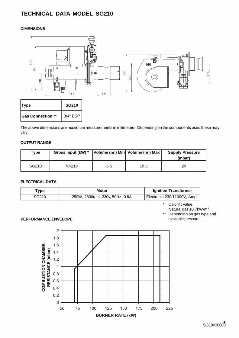
TECHNICAL DATA MODEL SG210
SG10030603
PERFORMANCE ENVELOPE
* Calorific value:Natural gas 10.7kW/m3
** Depending on gas type andavailable pressure
OUTPUT RANGE
The above dimensions are maximum measurements in milimeters. Depending on the components used these mayvary.
DIMENSIONS
ELECTRICAL DATA
SG210
Type Gross Input (kW) * Volume (m³) Min Volume (m³) Max Supply Pressure (mbar)
SG210 70-210 6.5 10.3 20
Type Motor Ignition Transformer
SG210 250W, 2800rpm, 230v, 50Hz, 0.8A Electronic 230/11000V, Ampl.
Type SG210
Gas Connection ** 3/4" BSP

6
SETTING COMBUSTION HEADThe burner head assembly is adjustablelongitudinally so that the restrictionbetween the air diffuser and the throatof the flame tube effectively meters thecombustion air.
METHOD OF ADJUSTMENTEnsure that the burner is isolated fromthe electricity supply.Remove the hinge pin.Unplug any electrical connections thatare restricting movement.Swing the burner body away slowly.Undo the head clamping bolt from thetop of the hinged extension.Lift out the burner head assembly takingcare of the sealing gasket.If the head is to be completely removedunclip the ignition and flame detectorleads, remove the earth connection.
Adjust the position of the assembly inthe socket of the supporting elbowaccording to burner output required.Secure the assembly and replace inreverse order taking care that theassembly sits squarely on the gasinlet spigot and is squarely locked inposition by its clamping bolt. Ensurethat when the burner is swung backinto position the ignition and flamedetector leads are carefully fixed backonto their respective connections (theterminal ends are dissimilar so thatthey cannot be wrongly connected).
BURNER GAS CONTROLSLOW GAS PRESSURE SWITCH - IFFITTEDThe low gas pressure switch is locatedon the inlet side of the gas valve. It isrequired to monitor inlet gas pressureduring burner operation. The low gaspressure switch is wired in series withthe appliance controlling instrumentsand in the event of gas pressure failurewill cause the burner to effect a safetyshut down.GAS VALVE MULTIBLOC
SG210 burners are supplied for On/Off or High/Low operation and for use with single phase electrical supply. Where aninstruction or information is applicable to only one of the burner types, single or two stage, then this is indicated in the text.This manual is structured to enable the user to proceed from the delivery of the burner to its commissioning and use.The conditions to be fulfilled and the controls and adjustments to be used are dealt with in the sequence that should befollowed for the correct assembly installation and use. Commissioning procedures are described and the location ofnecessary controls and adjustments to undertake these runs are illustrated and supported by appropriate tables andgraphs.Routine Maintenance and Fault Finding complete the manual; literature on proprietary components is available on request.
GENERAL INSTRUCTIONS
SINGLE STAGE (ON/OFF)The gas valve is of the multibloc typeincorporating start rate, safety andmain valves and pressure governor.Valve adjustments are detailed in theGas Controls and Adjustments section.
TWO STAGE (HIGH/LOW)The gas valve is of the multibloc typeincorporating start rate, safety and twostage valve and pressure governor.Valve adjustments are detailed in theGas Controls and Adjustment section.
ADJUSTMENT MARKINGS
NUMBER 1 THIS END

7
Air Adjustment Scale
GENERAL INSTRUCTIONS - Continued
WITH 1.
8mba
r RESIS
TANCE
WITHOUT RESISTANCE
BURNER AIR CONTROLSAir for combustion is controlled by anadjustable air flap located inside the airinlet on the right hand side of theburner, viewed from the rear. A quadrantcalibrated 0 - 10 for the visual setting ofthe air control is located on the top ofthe air inlet. To increase the flow ofcombustion air, slacken the lockingscrew and turn the air flap quadrantanti-clockwise. To decrease the flow of
combustion air turn the air flap quadrantclockwise. Re-tighten the locking screwafter any adjustments are made.A graph is provided below givingapproximate setting positions for theair control according to firing rate.Full combustion analysis should beperformed for the final precise settingof the air damper as described in thecommissioning instructions.
AIR DIFFUSERThe air diffuser is fitted to the front endof the inner assembly and locatedwithin the flame tube.It controls the volume of combustion airand creates a pressure drop over theburner head to ensure good fuel/airmixing and flame stability. Thispressure drop is varied according togas rate by the adjustment of theburner head.
FLAME MONITORPROBEThe flame probe (ioisation probe) islocated on the burner head and isrequired to supervise the safe operationof the burner under all workingconditions. A good earth close to theflame is required for the operation of theprobe.
UVAs an option burners can be fitted withan ultraviolet cell (UV) cell to detectthe presence of the flame.
BURNER OPERATING SEQUENCESingle Stage (On/Off) BurnersThe operating sequence begins with apre-purge on full air, then start rate gasflame which when proved allows theburner to operate on main flame, thento the “OFF” position after the demandis satisfied. The operation is determinedby the appliance control instruments.Two Stage (High/Low) BurnersThe sequence begins with an air pre-purge on full air, followed by start rategas flame which when proved allowsthe burner to operate on High/Low/Off.
The operation is determined by thedemand of the appliance controlinstruments.
FLUE AND CHIMNEYREQUIREMENTSThe top of the Chimney/Flue should beabove all roofs within a radius of 10metres.Check that it is suitable for use withgas fired appliances. Reference shouldbe made to Local Authority and otherregulations governing suchinstallations.Ensure that the flue pipe from theappliance does not protrude into thechimney beyond the wall thicknessand is sealed throughout its run.???If more than one appliance is connectedto a common flue/chimney, ensurethat the cross section of the flue/chimney is adequate for the total volumeof flue gases from all the appliances.
PLANT ROOM VENTILATIONAn adequate supply of dust free, freshair is required for the burner at both highand low level in accordance with allappropriate local and nationalstandards.
GAS SUPPLYThe gas supply to the burner must beconstructed and installed to complywith local conditions and appropriateCodes and Standards. It should be ofsufficient size to satisfy the pressure/volume requirements of the burner toensure its operation.It is essential that a manual shut-off isfitted upstream of the burner gas trainfor the isolation of the burner duringservicing and maintenance.The valve size must not be less thanthe burner valve train or it will createrestriction to gas flow.

8
If the hinged extension/flame tube assembly is not fitted tothe fan case assembly, it should be fitted before the burneris mounted using the studs provided. Ensure that the gas inletconnection is at the bottom.Once the burner is mounted open the hinged extension,connect the flame probe and ignition cables. The terminalends are dissimilar and cannot be wrongly connected.The gas train can now be fitted to the hinged extension.
• Ensure that the gaskets are seated correctly whentightening the assembly.
• If the burner is to be fitted to a new packaged unit, referto the manufacturers recommendations.
• If the burner is to be used with an existing applianceprepare the mounting flange.
• Ensure the joint between appliance and burner iseffectively sealed with the gasket provided.
MOUNTING THE BURNER
ELECTRICAL
EXTERNAL WIRING
ADDITIONAL CONNECTIONS FOR HIGH/LOW VALVES
7 PIN BLACK/BROWNWIELAND PLUG
4 PIN BROWNWIELAND PLUG
ON/OFF VALVES
ELECTRICAL POWER SUPPLYConnect a single phase 50Hz electrical supply to the burner observing all applicable IEE Regulations. Refer to theconnection diagram below or the wiring diagram contained in the instruction pack supplied with the burner.
ELECTRICAL CONNECTIONSUse these connections if Wieland plugs are fitted to the burner, if no plugs are fitted refer to the contol box connectionsdiagram on Page 10 for connections direct to the control box.
BURNER MOUNTING DETAILDIMS IN MM
9
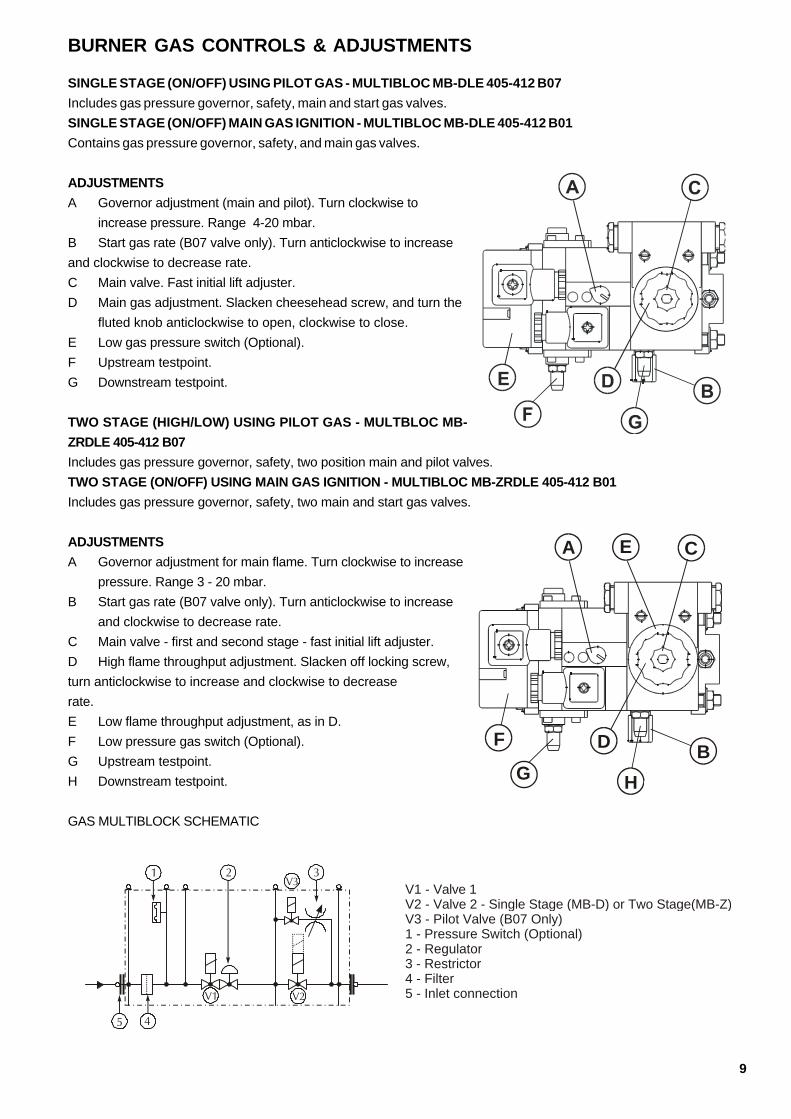
BURNER GAS CONTROLS & ADJUSTMENTS
SINGLE STAGE (ON/OFF) USING PILOT GAS - MULTIBLOC MB-DLE 405-412 B07Includes gas pressure governor, safety, main and start gas valves.SINGLE STAGE (ON/OFF) MAIN GAS IGNITION - MULTIBLOC MB-DLE 405-412 B01Contains gas pressure governor, safety, and main gas valves.
ADJUSTMENTSA Governor adjustment (main and pilot). Turn clockwise to
increase pressure. Range 4-20 mbar.B Start gas rate (B07 valve only). Turn anticlockwise to increaseand clockwise to decrease rate.C Main valve. Fast initial lift adjuster.D Main gas adjustment. Slacken cheesehead screw, and turn the
fluted knob anticlockwise to open, clockwise to close.E Low gas pressure switch (Optional).F Upstream testpoint.G Downstream testpoint.
TWO STAGE (HIGH/LOW) USING PILOT GAS - MULTBLOC MB-ZRDLE 405-412 B07Includes gas pressure governor, safety, two position main and pilot valves.TWO STAGE (ON/OFF) USING MAIN GAS IGNITION - MULTIBLOC MB-ZRDLE 405-412 B01Includes gas pressure governor, safety, two main and start gas valves.
ADJUSTMENTSA Governor adjustment for main flame. Turn clockwise to increase
pressure. Range 3 - 20 mbar.B Start gas rate (B07 valve only). Turn anticlockwise to increase
and clockwise to decrease rate.C Main valve - first and second stage - fast initial lift adjuster.D High flame throughput adjustment. Slacken off locking screw,turn anticlockwise to increase and clockwise to decreaserate.E Low flame throughput adjustment, as in D.F Low pressure gas switch (Optional).G Upstream testpoint.H Downstream testpoint.
GAS MULTIBLOCK SCHEMATIC
A E C
B
H
D
G
F
1 3
V1 V2
V3
5
2
4
V1 - Valve 1V2 - Valve 2 - Single Stage (MB-D) or Two Stage(MB-Z)V3 - Pilot Valve (B07 Only)1 - Pressure Switch (Optional)2 - Regulator3 - Restrictor4 - Filter5 - Inlet connection

10
CONTROL BOX
INTRODUCTION - MMI810The burner control box MMI 810 controls and supervises forced draught burners for gas and dual fuel.The syncronous motor controls sequence timings with speed reducer gears as the drive for the switching cam.The following important indicating and operating elements are located on the front panel of the automatic control:– Illuminated push button for indication of locout faults and for resetting the burner– Informative programme display comprising rotating dial with colour coded segments. This information system providescontinuous indication of the actual state of the burner (including monitoring of the start-up phase) and informs about thepossible cause of a lockout.
APS
IP Z M V1 V2 XF
1 A/32 B4 5 6 7 8 9 S1
MS Main SwitchLT Limit ThermostatCT Control ThermostatIP Ionization ProbeZ IgnitionM Burner MotorV1 Solenoid Valve 1st StageV2 Solenoid Valve 2nd StageAPS Air Pressure SwitchXF External Fault Indication------- External Wiring
LT
CT
MS
CO
NT
RO
L IN
ST
RU
ME
NT
S
CO
NT
RO
L S
EQ
UE
NC
E
CONTROL BOX CONNECTIONS
LN E
2
MEASUREMENT OF THE FLAME SIGNAL
Place micro ammeter in series with ionisation probe.
Minimum signal strength 5 µA
CONTROL BOX FAULT INDICATION
Burner does not operate, sequence indicator does not move:– Faulty electrical connection.– Thermostat or gas pressure switch (if fitted) ”OFF”.
Burner does not operate, programme indicator rotatescontinuously:– Air pressure monitor switch not in starting position. (Workingcontact must be open).– Connection from terminal 1 to terminal 9 broken– mains voltage < 180V
The automatic control switches to fault condition shortlyafter the start of the pre-purge time (line within the blue zone):– Air pressure switch does not close.– No load on terminal 5 (Air pressure switch contacts open).– Flame signal.
Automatic control switches to fault condition during theprepurging (blue zone):– No flame formation (no ignition, valve does not open, etc.)– No flame signal or flame signal too weak (flame does not adhere,poor insulation of the flame detection probe,burner not properly connected to the earthconductor).
Automatic control switches to fault conditionduring the operating position (red, greenzone):– Flame lift-off– Air pressure switch contact open– Flame signal too weak.

11
The capacity of Selectos SG burnersusing natural gas has been deter-mined at a minimum supply pressureof 20mbar (max 40mbar). For LPG thesupply pressure should be between25mbar and 40mbar.These burners will operatesatisfactorily on gas supply pressureslower than those quoted above, butburner capacity will be reducedaccordingly.Any LPG high pressure regulator fittedmust be equiped with over pressureshut off protection.Turn off the gas supply at the manualshut off valve upstream of the gas valveinlet.Fit an approved pressure measuringinstrument at the pressure test pointon the inlet of the gas MultiBloc. Turnon the gas supply. Check gas pres-sure, this will record static pressurewhich will be higher than running pres-sure, which should not be less than17.8mbar when running on main flame.
INNER ASSEMBLYEnsure that the ignition electrode andionisation probe are correctly adjusted.Correct positioning is shown on theComponent Identification page.Ensure that the head has beenpositioned according to the gas rate.
GAS TYPEEnsure that the burner head is correctfor the type of gas to be used. Checkthe burner data plate.
PURGINGThe gas line is purged by loosening thescrew on the inlet pressure test nipple.Connect a plastic hose and conductthe gas into atmosphere. After purgingthe gas line re-tighten the screw.
LEAKAGE TESTINGWhen making a leak test of the gassupply system the gas valve should beclosed. Connect a pressure gauge to
IMPORTANTAfter each adjustment, the gas flow rate and flue gas analysis should be checked.
ALWAYSUse approved test equipment (Continually monitoring electronic equipment is recommended).
NEVERRely on a visual inspection of the flame as a guide to combustion quality.
the test nipple on the gas valve. Thetest pressure in the system should be1.5 x maximum inlet pressure orminimum 150 mbar. If there is anyleakage, locate the source by meansof soapy water or a leak detectionspray. After tightening repeat the test
DRY RUNTurn off the electricity supply to theburner. Close the manual gas shut-offvalve.To prevent the gas pressure (if fitted)switch from locking out, remove thecover and fit a temporary link.Adjust the thermostats to call for heatand switch on the electrical supply tothe burner, the pre-purging period willbegin (24-40 seconds). At the end ofthis period the pre-ignition period starts(3 seconds).The gas valve is energized and opensand the flame would be established. Atthe end of the safety time (3 to 5seconds) the control box will go tolockout. The gas valve will be de-energised and the motor will stoprunning. The dry run is complete.Ensure to remove the link from the gaspressure switch after the test is finished.
PRE-COMMISSIONING CHECKS
12
COMMISSIONING
Reference should be made to the Burner Gas Controls and Adjustment section of this manual for identificationand location of the following adjustments.None of these adjustments should be made in isolation. One adjustment will have an effect on another. It istherefore essential that the combustion quality and gas throughput are monitored during the commissioningprocedure
PILOT BYPASS ADJUSTMENT(B07 VALVE ONLY)
The bypass valve opens at the same time as the first valve. Ignition gas flow is set by using bypass restrictor.Turn anticlockwise to increase and clockwise to decrease rate.If the governor pressure is set too low there will be insufficient pressure for the pilot bypass to operate.
ADJUSTING MAIN GAS GOVERNOR
With a screwdriver turn the adjusting screw to its minimum position then turn back four complete revolutions.This will give a reduced gas flow rate to enable further adjustments to commence.Note: Should the burner lockout when establishing start and main flames then the probable cause is air or inertgas in the gas line. This can be removed by purging the line through the pressure test points located on the gasMultiBloc. Alternatively, there may be insufficient pressure on the gas governor.
SETTING MAIN FLAME GAS RATE
Switch the burner on and allow it to establish main flame.Check the gas throughput with a gas meter or with other approved measuring instrument.With a screwdriver slowly adjust the gas governor to increase the gas volume through the burner to the raterequired for the appliance.Ensure that other appliances served by the same meter are isolated when gas throughputs are being adjusted.With the gas flow rate for main flame set and the burner running with stable flame, the flue gases can now bechecked for CO2 and O2 with suitable combustion testing instruments.Figures of 9-10% CO2 and 3-5% O2 are acceptable. For reasons of safety the CO (carbon monoxide) should bechecked and should not exceed 100 ppm.To achieve good combustion efficiency or if the CO content is exceeded, adjustments to the air and gas settingscan now be made while the burner is running on main flame.
ADJUSTING THE MAIN VALVE FAST INITIAL LIFT.B01 VALVE
The adjuster acts as a damper to the main valve, controlling the rate of opening after initial lift. This adjustmentis used to reduce the volume of gas that the valve passes during the ignition safety phase. Switch off and restartthe burner. Note the quality of the light up during the ignition stage. If the light up is weak, then increase theamount of fast initial lift by turning the adjuster anticlockwise. Turn the adjuster clockwise if a heavy light upis encountered. Repeat until a satisfactory setting is achieved.B07 VALVE - The adjuster acts to control the rate of change between high and low position. Turn the valve clockwise toslow down the rate and anticlockwise to increase the rate of change.
SETTING LOW FLAME RATE HIGH/LOW BURNER(MB-ZRDLE VALVES ONLY)
Low flame gas rate is achieved by adjusting the low gas setting of the two position solenoid valve on the gasMultiBloc.Turn the low gas rate adjusting ring on the gas MultiBloc to achieve low flame throughput (refer to Gas Controlsand Adjustments). Care must be taken so as not to exceed the turndown ratio for the burner model beingcommissioned.
13
AIR PRESSURE SWITCH
Located on the right side of the burner casing viewed from the rear, it is required to prove adequate air flowthroughout the burner operating cycle. Flow failure at any stage following the first few seconds of pre-purgewill lockout the burnerTo set the Air Pressure Switch :-Switch off the electrical supply to the burner.Remove the air pressure switch cover. Fit a manometer to the pressure switch to check the actual air pressureagainst the pressure switch dial setting.Switch on the electrical supply and allow two stage burners to establish low flame and single stage burnersto establish main flame.Slowly turn the adjusting dial clockwise until the flame is extinguished. The burner will go to lockout.Turn the dial one division anticlockwise and reset burner lockout. The burner will then continue through itscycle until either the start rate flame is established or the burner goes to its lockout position.If the burner goes to lockout repeat the procedure once per burner cycle until the start rate flame is established.Allow the burner to cycle to low flame (two stage) and main flame (single stage) and then turn the adjustingdial a further two divisions anticlockwise.Switch off the electrical supply to the burner, replace the air pressure switch cover and remove the manometer.
SETTING LOW GAS PRESSURE SWITCH
Isolate the burner and remove the gas pressure switch cover. Switch on the electrical supply and allow the burner toestablish main flame. Slowly turn the adjustment dial on the gas pressure switch clockwise until the flame is extinguishedand the burner shuts down. Turn the dial slowly anticlockwise one division at a time until the burner restarts and establishesmain flame. Recheck the performance and then turn the dial a further two divisions anticlockwise. Switch off the burnerand replace the gas pressure switch cover.
CHECK FLAME SIGNAL
With the burner isolated, connect in series with the ionisation probe and the gas burner control a DC Ammeter.Switch on the burner.Once the flame is established, the microammeter will record the signal strength. (Check high and low flameif applicable). A minimum reading of 5µA will give reliable operating conditions.Readings below this figure may arise from poor burner adjustment. Check and reset if found to be necessaryor refer to the section in Fault Finding.Switch off the power to the burner, remove the microammeter, and reconnect the ionisation probe.Check that all covers to components and locking devices are properly secured.Check that the appliance control instruments are set to safe limits.Commissioning is now complete.

14
ROUTINE SAFETY CHECKS
TO BE CARRIED OUT ONLY BY QUALIFIED AND EXPERIENCED PERSONNEL.Check that the plant room is ventilated at all times.Frequently inspect the air inlet of the burner and ensure that there are no obstructions to air flow.
FLAME DETECTION SYSTEM
FLAME PROBE (IOISATION PROBE) - IF FITTEDSwitch off the electrical supply to the burner. Break the flame signal circuit by removing any connection to the ionisationprobe.Switch on the electrical supply. Check that the burner locks out at the end of the ignition cycle.Switch off the electrical supply. Complete flame signal check circuit.Switch on the electrical supply. Reset lockout.
UV (ULTRA-VIOLET) CELLSwitch off the power supply to the burner. Remove the UV cell from the burner casing and cover the quartz glassenvelope to exclude any light. Do not touch the quartz glass with fingers.Switch on the power supply and during the pre-purge period show the UV cell to an external light source. The burnershould go immediately to lockout. Reset lockoutAllow the burner to to cycle and check that the burner locks out at the end of the ignition cycle. Switch off the powersupply. Replace UV cell switch on the power supply. Reset lockout.
ROUTINE MAINTENANCESwitch off electrical supply and gas supply to the burner.
COMBUSTION AIR FANAccess can be gained to the combustion air fan by removing the top cover of the fan casing.Clean the blades regularly with a stiff brush. Care should be taken to avoid damaging the fan blades. Check that the airinlet into the fan is clean.When re-assembling the fan casing ensure that the gasket is correctly located.
INNER ASSEMBLYOpen the hinged extension as follows:-Remove the MultiBloc plug from its socket on the control package.Remove the safety bolts from the hinged extension. Remove the pin appropriate to the direction in which the head is tobe opened.Open the hinged extension, disconnect the ignition electrode H.T. lead and if fitted the flame probe lead.Remove the locking screw securing the inner assembly gas pipe to its manifold. Carefully withdraw the inner assemblyfrom the hinged extension.
AIR DIFFUSER AND GAS NOZZLEClean using a stiff brush.
IGNITION ELECTRODEClean and check the electrode is not cracked or worn. Renew if necessary.Check the settings of the ignition electrode and flame rectification probe, and reset if necessary. Replace all compo-nents and covers, and secure all fittings. The burner is now ready for operation. Switch on the electricity supply and gassupply to the burner.
REPLACEMENT OF DUNGS MULTIBLOCShould any of the above valves require replacing due to mechanical or electrical failure, then the burner will require re-commissioning to restore the proper combustion and performance values. It is essential that replacement of thesecomponents and re-commissioning of the burner be undertaken only by qualified engineers.
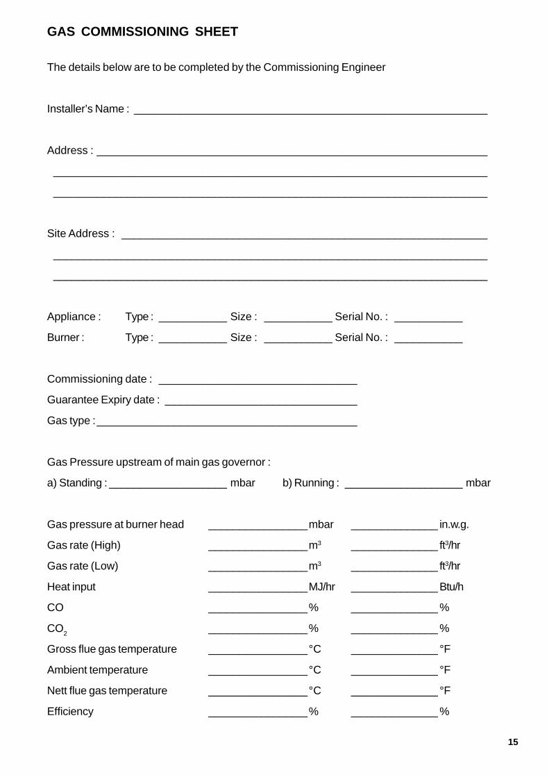
15
The details below are to be completed by the Commissioning Engineer
Installer’s Name : _________________________________________________________
Address : _______________________________________________________________
______________________________________________________________________
______________________________________________________________________
Site Address : ___________________________________________________________
______________________________________________________________________
______________________________________________________________________
Appliance : Type : ___________ Size : ___________ Serial No. : ___________
Burner : Type : ___________ Size : ___________ Serial No. : ___________
Commissioning date : ________________________________
Guarantee Expiry date : _______________________________
Gas type :__________________________________________
Gas Pressure upstream of main gas governor :
a) Standing : ___________________ mbar b) Running : ___________________ mbar
Gas pressure at burner head ________________mbar ______________ in.w.g.
Gas rate (High) ________________m3 ______________ ft3/hr
Gas rate (Low) ________________m3 ______________ ft3/hr
Heat input ________________MJ/hr ______________ Btu/h
CO ________________% ______________ %
CO2 ________________% ______________ %
Gross flue gas temperature ________________°C ______________ °F
Ambient temperature ________________°C ______________ °F
Nett flue gas temperature ________________°C ______________ °F
Efficiency ________________% ______________ %
GAS COMMISSIONING SHEET
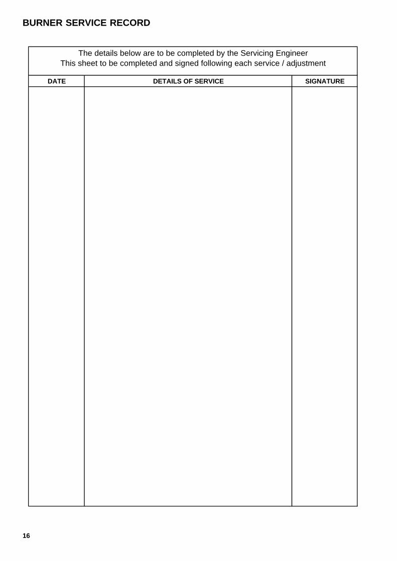
16
DATE DETAILS OF SERVICE SIGNATURE
The details below are to be completed by the Servicing EngineerThis sheet to be completed and signed following each service / adjustment
BURNER SERVICE RECORD

17
FAULT FINDING
Any modifications to the installation or component settings resulting from actions suggested below mayrequire the re-establishment of the various settings as indicated earlier in this manual.
BURNER MOTOR FAILS TO START
Check:
• that the electrical supply is sufficient and the burner is correctly wired.
• all fuses for continuity and size.
• all control instruments are “calling for heat”.
• the gas train is electrically connected.
• the control box is not locked out (e.g. signal lamp faulty). (If the control box is locked out, pressthe reset button).
• there is sufficient gas pressure.
• the burner probe is not earthed.
• the air pressure switch is in the “start” position, as follows: -
Switch off the electrical supply. Remove the plug-in assembly from the control box base. Check for anopen circuit between the air pressure switch terminals.
If there is continuity between terminals, turn the dial on the air pressure switch fully anticlockwise to theminimum setting. If there is now an open circuit, the air pressure switch is in order, otherwise the airpressure switch is faulty and must be renewed.
If the air pressure switch isn't in its made position the motor will start for approximately 2 to 3 seconds,it then will lockout for 10 seconds before attempting a further start. If it is still in the made position alockout will occur.
START FAILURE WITHOUT IGNITION
Check:
• The air pressure switch is set correctly.
• The electrode is correctly set and the porcelain is not cracked.
• The ignition transformer is not faulty.
• The control box is not faulty.
START FAILURE WITHOUT FLAME
If the start flame is not properly established, the safety circuit of the sequence controller will causelockout in one second.
The cause may be insufficient signal to the flame detection device. Alternatively the flame signal circuitmay be incomplete, or there is insufficient gas to allow the flame monitoring device to take over andsignal the sequence controller to continue its cycle. This may be remedied by adjusting the fast initial liftof the downstream safety valve.
Check:
• The probe is correctly positioned.
• For bad earth continuity/faulty wiring.
• The ignition tranformer for crossed polarity.
• The flame signal circuit is incomplete.
SG100 01 05

18
FAULT FINDING - CONTINUED
BURNER FAILS TO ESTABLISH MAIN FLAME.
Check:
• The gas valves are operating correctly.
• The combustion air is set correctly.
• There is sufficient gas.
• The control box is not faulty.
INCORRECT ROTATION OF BURNER MOTOR
Motor rotates clockwise viewed from the shaft end. If the burner motor rotation is incorrect, the singlephase motor should be renewed. On three phase motors, interchange any two phases. In normalcircumstances, this will correct the rotation.

19

20
NU-WAY LIMITED, P O Box 1, Vines Lane,Droitwich, Worcs, WR9 8NA, England.Tel: (01905) 794331 & 794242 (Direct Dial)Fax: (01905) 794017 & 795829 (Spares Dept)E-mail: [email protected]: www.nu-way.co.uk
Nu-way’s policy is one ofcontinuous improvement. Theright to change prices andspecifications without notice isreserved.An Enertech Group Company