sfs-8622 series user guide
TRANSCRIPT

SFS-8622 Series User Guide

Thank You for Choosing RossYou've made a great choice. We expect you will be very happy with your purchase of Ross Technology.
Our mission is to:
1. Provide a Superior Customer Experience
• offer the best product quality and support
2. Make Cool Practical Technology
• develop great products that customers love
Ross has become well known for the Ross Video Code of Ethics. It guides our interactions and empowers our employees. I hope you enjoy reading it below.
If anything at all with your Ross experience does not live up to your expectations be sure to reach out to us at [email protected].
David RossCEO, Ross [email protected]
Ross Video Code of EthicsAny company is the sum total of the people that make things happen. At Ross, our employees are a special group. Our employees truly care about doing a great job and delivering a high quality customer experience every day. This code of ethics hangs on the wall of all Ross Video locations to guide our behavior:
1. We will always act in our customers’ best interest.
2. We will do our best to understand our customers’ requirements.
3. We will not ship crap.
4. We will be great to work with.
5. We will do something extra for our customers, as an apology, when something big goes wrong and it's our fault.
6. We will keep our promises.
7. We will treat the competition with respect.
8. We will cooperate with and help other friendly companies.
9. We will go above and beyond in times of crisis. If there's no one to authorize the required action in times of company or customer crisis - do what you know in your heart is right. (You may rent helicopters if necessary.)

SFS-8622 Series · User Guide• Ross Part Number: 8622DR-004-04
• Release Date: August 26, 2019.
The information contained in this Guide is subject to change without notice or obligation.
Copyright
©2019 Ross Video Limited, Ross®, and any related marks are trademarks or registered trademarks of Ross Video Limited. All other trademarks are the property of their respective companies. PATENTS ISSUED and PENDING. All rights reserved. No part of this publication may be reproduced, stored in a retrieval system, or transmitted in any form or by any means, mechanical, photocopying, recording or otherwise, without the prior written permission of Ross Video. While every precaution has been taken in the preparation of this document, Ross Video assumes no responsibility for errors or omissions. Neither is any liability assumed for damages resulting from the use of the information contained herein.
Patents
Patent numbers US 7,034,886; US 7,508,455; US 7,602,446; US 7,802,802 B2; US 7,834,886; US 7,914,332; US 8,307,284; US 8,407,374 B2; US 8,499,019 B2; US 8,519,949 B2; US 8,743,292 B2; GB 2,419,119 B; GB 2,447,380 B; and other patents pending.
Notice
The material in this manual is furnished for informational use only. It is subject to change without notice and should not be construed as commitment by Ross Video Limited. Ross Video Limited assumes no responsibility or liability for errors or inaccuracies that may appear in this manual.
Safety Notices
Refer to the “Important Regulatory and Safety Notices” document that accompanied your product.
Statement of Compliance
This product has been determined to be compliant with the applicable standards, regulations, and directives for the countries where the product is marketed.
Compliance documentation, such as certification or Declaration of Compliance for the product is available upon request by contacting [email protected]. Please include the product; model number identifiers and serial number and country that compliance information is needed in request.
EMC Notices
US FCC Part 15
This equipment has been tested and found to comply with the limits for a class A Digital device, pursuant to part 15 of the FCC Rules.
These limits are designed to provide reasonable protection against harmful interference when the equipment is operated in a Commercial environment. This equipment generates, uses, and can radiate radio frequency energy and, if not installed and used in accordance with the instruction manual, may cause harmful interference to radio
communications. Operation of this equipment in a residential area is likely to cause harmful interference in which case the user will be required to correct the interference at his own expense.
Canada
This Class “A” digital apparatus complies with Canadian ICES-003 and part 15 of the FCC Rules.
Cet appareil numerique de la classe “A” est conforme a la norme NMB-003 du Canada.
European Union
This equipment is in compliance with the essential requirements and other relevant provisions established under regulation (EC) No 765/2008 and Decision No 768/2008/EC referred to as the “New Legislative Framework”.
Australia/New Zealand
This equipment is in compliance with the provisions established under the Radiocommunications Act 1992 and Radiocommunications Labeling (Electromagnetic Compatibility) Notice 2008.
Korea
This equipment is in compliance with the provisions established under the Radio Waves Act.
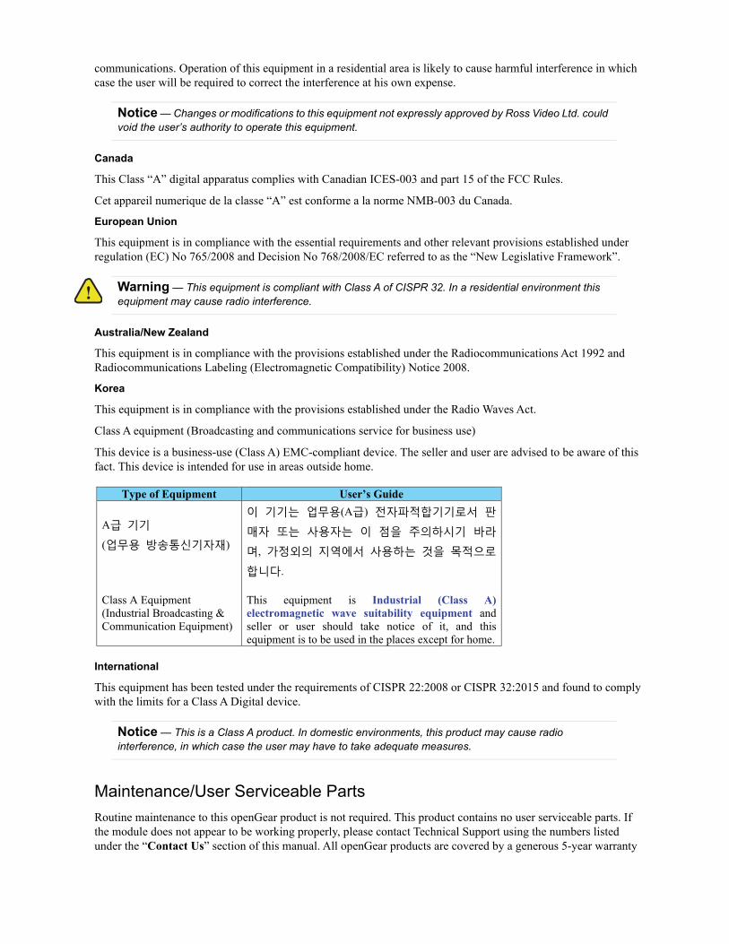
Class A equipment (Broadcasting and communications service for business use)
This device is a business-use (Class A) EMC-compliant device. The seller and user are advised to be aware of this fact. This device is intended for use in areas outside home.
International
This equipment has been tested under the requirements of CISPR 22:2008 or CISPR 32:2015 and found to comply with the limits for a Class A Digital device.
Maintenance/User Serviceable Parts
Routine maintenance to this openGear product is not required. This product contains no user serviceable parts. If the module does not appear to be working properly, please contact Technical Support using the numbers listed under the “Contact Us” section of this manual. All openGear products are covered by a generous 5-year warranty
Notice — Changes or modifications to this equipment not expressly approved by Ross Video Ltd. could void the user’s authority to operate this equipment.
Warning — This equipment is compliant with Class A of CISPR 32. In a residential environment this equipment may cause radio interference.
Notice — This is a Class A product. In domestic environments, this product may cause radio interference, in which case the user may have to take adequate measures.
Type of Equipment User’s Guide
A
( )
Class A Equipment
(Industrial Broadcasting &
Communication Equipment)
(A )
,
.
This equipment is Industrial (Class A) electromagnetic wave suitability equipment and
seller or user should take notice of it, and this
equipment is to be used in the places except for home.

and will be repaired without charge for materials or labor within this period. See the “Warranty and Repair Policy” section in this manual for details.
Environmental Information
The equipment may contain hazardous substances that could impact health and the environment.
To avoid the potential release of those substances into the environment and to diminish the need for the extraction of natural resources, Ross Video encourages you to use the appropriate take-back systems. These systems will reuse or recycle most of the materials from your end-of-life equipment in an environmentally friendly and health conscious manner.
The crossed-out wheeled bin symbol invites you to use these systems.
If you need more information on the collection, reuse, and recycling systems, please contact your local or regional waste administration. You can also contact Ross Video for more information on the environmental performances of our products.
Company Address
Ross Video Limited Ross Video Incorporated
8 John Street P.O. Box 880
Iroquois, Ontario, K0E 1K0 Ogdensburg, New York
Canada USA 13669-0880
General Business Office: (+1) 613 • 652 • 4886
Fax: (+1) 613 • 652 • 4425
Technical Support: (+1) 613 • 652 • 4886
After Hours Emergency: (+1) 613 • 349 • 0006
E-mail (Technical Support): [email protected]
E-mail (General Information): [email protected]
Website: http://www.rossvideo.com


SFS-8622 Series User Guide (v4.0) Contents • i
Contents
Introduction 11Related Publications ...............................................................................................................................................11Documentation Conventions ..................................................................................................................................11
Interface Elements ...............................................................................................................................................11User Entered Text ...............................................................................................................................................11Referenced Guides ..............................................................................................................................................11Menu Sequences ..................................................................................................................................................12Important Instructions .........................................................................................................................................12
Contacting Technical Support ................................................................................................................................12
Before You Begin 13Overview ................................................................................................................................................................13
Features ...............................................................................................................................................................13SFS-8622-A Functional Block Diagrams ..............................................................................................................14SFS-8622-B Functional Block Diagrams ..............................................................................................................16SFS-8622-IC Functional Block Diagram ...............................................................................................................17SFS-8622-OC Functional Block Diagram .............................................................................................................18SFS-8622-AIC Functional Block Diagrams ..........................................................................................................18SFS-8622-AOC Functional Block Diagram ..........................................................................................................19Frame Synchronizer Overview ..............................................................................................................................20User Interfaces .......................................................................................................................................................21
DashBoard Control System .................................................................................................................................21Card-edge Monitoring .........................................................................................................................................21SNMP Monitoring and Control ...........................................................................................................................21
Hardware Overview 23Card Overview .......................................................................................................................................................23Control and Monitoring Features ...........................................................................................................................23
Status and Selection LEDs ..................................................................................................................................24
Physical Installation 25Before You Begin ..................................................................................................................................................25
Static Discharge ..................................................................................................................................................25Unpacking ...........................................................................................................................................................25
Supported Rear Modules ........................................................................................................................................25Installing a Rear Module ........................................................................................................................................25Installing a Card .....................................................................................................................................................26
Cabling 27SFS-8622-A Cabling ..............................................................................................................................................27
Six AES Inputs Only ...........................................................................................................................................27Six AES Outputs Only ........................................................................................................................................27Three AES Inputs and Three AES Outputs .........................................................................................................28
SFS-8622-B Cabling ..............................................................................................................................................28Eight AES Inputs ................................................................................................................................................28Eight AES Outputs ..............................................................................................................................................29Four AES Inputs and Four AES Outputs ............................................................................................................29
SFS-8622-IC Cabling .............................................................................................................................................30SFS-8622-OC Cabling ...........................................................................................................................................30SFS-8622-AIC Cabling ..........................................................................................................................................31
ii • Contents SFS-8622 Series User Guide (v4.0)
Four AES Inputs and Four Analog Inputs ...........................................................................................................31Four Analog Inputs and Four AES Outputs ........................................................................................................31
SFS-8622-AOC Cabling ........................................................................................................................................32Four AES Inputs and Four Analog Outputs ........................................................................................................32Four AES Outputs and Four Analog Outputs .....................................................................................................32
Using DashBoard 33Before You Begin ...................................................................................................................................................33Accessing the SFS-8622 in DashBoard .................................................................................................................33
Video Setup 35Overview ................................................................................................................................................................35Selecting a Reference Source .................................................................................................................................35
Frame Rate Compatibility ...................................................................................................................................35Selecting a Reference Source ..............................................................................................................................36
Adding a Delay .......................................................................................................................................................37Adjusting with Video Proc Amps ..........................................................................................................................39ANC Processing .....................................................................................................................................................39
HANC Processing ...............................................................................................................................................39VANC Processing ...............................................................................................................................................40
Selecting a Test Pattern ..........................................................................................................................................40Configuring the Moving Box Test Feature ............................................................................................................41Specifying the Output During a Loss of Input .......................................................................................................42Specifying a Custom Color ....................................................................................................................................42
Audio Setup 45Selecting an AES Configuration ............................................................................................................................45Configuring the AES Inputs ...................................................................................................................................46Configuring the AES Outputs ................................................................................................................................46Configuring the Analog Inputs ...............................................................................................................................47Configuring the Analog Outputs ............................................................................................................................48Embedded Outputs .................................................................................................................................................49
Setting up Embedded Outputs .............................................................................................................................50Configuring the Embedded Output Groups .........................................................................................................50
Embedding PCM and Non-PCM Signals ...............................................................................................................51Embedding PCM Signals ....................................................................................................................................51Embedding Non-PCM Signals ............................................................................................................................51
Software Upgrades 53
DashBoard Menus 55Status Tabs .............................................................................................................................................................55
Signal Tab ............................................................................................................................................................55Hardware Tab ......................................................................................................................................................57Product Tab .........................................................................................................................................................57
Setup Tab ................................................................................................................................................................58Proc Amp Tab ........................................................................................................................................................61VANC Processing Tab ...........................................................................................................................................61Input Status Tab .....................................................................................................................................................62
Video Input & Embedded Tab ............................................................................................................................62Audio Tab ............................................................................................................................................................62
Embedded Outputs Tab ..........................................................................................................................................63Analog Inputs Tab ..................................................................................................................................................64Analog Outputs Tab ...............................................................................................................................................64AES Inputs Tab ......................................................................................................................................................65
SFS-8622 Series User Guide (v4.0) Contents • iii
AES Outputs Tabs ..................................................................................................................................................65Alarm Enables Tab ................................................................................................................................................66
Technical Specifications 69SDI Input .............................................................................................................................................................69SDI Outputs .........................................................................................................................................................69AES Inputs ..........................................................................................................................................................70AES Outputs .......................................................................................................................................................70Analog Inputs .....................................................................................................................................................70Analog Outputs ...................................................................................................................................................71Environmental .....................................................................................................................................................71Total Power Consumption ..................................................................................................................................71
Channel Status Data 73Channel Status Data Table .....................................................................................................................................73Passing the Status Bytes .........................................................................................................................................73
Service Information 75Troubleshooting Checklist .....................................................................................................................................75
Bootload Button ..................................................................................................................................................75Warranty and Repair Policy ...................................................................................................................................75
Glossary 77

iv • Contents SFS-8622 Series User Guide (v4.0)

SFS-8622 Series User Guide (v4.0) Introduction • 11
IntroductionThis guide covers the installation, configuration, and use of the SFS-8622 series. The following chapters are included:
• “Introduction” summarizes the guide and provides important terms, and conventions.
• “Before You Begin” provides general information to keep in mind before installing and configuring your card.
• “Hardware Overview” provides a basic introduction to the hardware features of the card.
• “Physical Installation” provides instructions for the physical installation of the card and its rear module.
• “Cabling” provides an overview of connecting input and output devices to the rear module.
• “Using DashBoard” briefly summarizes how to launch DashBoard and access the SFS-8622 interfaces.
• “Video Setup” provides a general overview of the video setup options available for your card.
• “Audio Setup” provides a general overview of the options in DashBoard for configuring the audio features of your card.
• “Software Upgrades” provides instructions for upgrading the software for your SFS-8622 using DashBoard.
• “DashBoard Menus” summarizes the SFS-8622 menus, items, and parameters in DashBoard.
• “Technical Specifications” provides technical specification details on the SFS-8622.
• “Channel Status Data”provides additional information for channel status bits.
• “Service Information” provides information on the warranty and repair policy for your card.
• “Glossary” provides a list of terms used throughout this guide.
Related Publications
It is recommended to consult the following Ross documentation before installing and configuring your SFS-8622 series card:
• DashBoard User Manual, Ross Part Number: 8351DR-004
• MFC-OG3-N and MFC-8322-S User Manual, Ross Part Number: 8322DR-004
• OG3-FR Series User Manual, Ross Part Number: 8322DR-005
• OGX-FR Series User Manual, Ross Part Number: 8322DR-204
Documentation Conventions
Special text formats are used in this guide to identify parts of the user interface, text that a user must enter, or a sequence of menus and sub-menus that must be followed to reach a particular command.
Interface Elements
Bold text is used to identify a user interface element such as a dialog box, menu item, or button. For example:
In the Network tab, click Apply.
User Entered Text
Courier text is used to identify text that a user must enter. For example:
In the Language box, enter English.
Referenced Guides
Text set in bold and italic represent the titles of referenced guides, manuals, or documents. For example:

12 • Introduction SFS-8622 Series User Guide (v4.0)
For more information, refer to the DashBoard User Manual.
Menu Sequences
Menu arrows are used in procedures to identify a sequence of menu items that you must follow. For example, if a step reads “File > Save As,” you would click the File menu and then click Save As.
Important Instructions
Star icons are used to identify important instructions or features. For example:
Contact your IT department before connecting to your facility network to ensure that there are no conflicts. They will provide you with an appropriate value for the IP Address, Subnet Mask, and Gateway for your device.
Contacting Technical Support
At Ross Video, we take pride in the quality of our products, but if problems occur, help is as close as the nearest telephone.
Our 24-hour Hot Line service ensures you have access to technical expertise around the clock. After-sales service and technical support is provided directly by Ross Video personnel. During business hours (Eastern Time), technical support personnel are available by telephone. After hours and on weekends, a direct emergency technical support phone line is available. If the technical support person who is on call does not answer this line immediately, a voice message can be left and the call will be returned shortly. This team of highly trained staff is available to react to any problem and to do whatever is necessary to ensure customer satisfaction.
• Technical Support: (+1) 613-652-4886
• After Hours Emergency: (+1) 613-349-0006
• E-mail: [email protected]
• Website: http://www.rossvideo.com
SFS-8622 Series User Guide (v4.0) Before You Begin • 13
Before You BeginShould you have a question pertaining to the installation or operation of your SFS-8622, please contact us at the numbers listed in “Contacting Technical Support” on page 12. Our technical support staff is always available for consultation, training, or service.
Overview
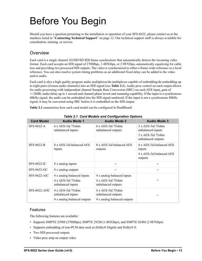
Each card is a single channel 3G/HD/SD SDI frame synchronizer that automatically detects the incoming video format. Each card accepts an SDI signal of 270Mbps, 1.485Gbps, or 2.987Gbps, automatically equalizing for cable loss and providing two processed SDI outputs. The video is synchronized to either a frame-wide reference or a local reference. You can also resolve system timing problems as an additional fixed delay can be added to the video and/or audio.
Each card is also a high quality program audio multiplexer/de-multiplexer capable of embedding/de-embedding up to eight pairs (sixteen audio channels) into an SDI signal (see Table 2.1). Audio proc control on each output allows for audio processing with independent channel Sample Rate Conversion (SRC) on each AES input, gain of +/-20dB, audio delay up to 1 second and channel phase invert and summing capability. If the input is a synchronous 48kHz signal, the audio can be embedded into the SDI signal unaltered. If the input is not a synchronous 48kHz signal, it may be converted using SRC before it is embedded on the SDI output.
Table 2.1 summarizes how each card model can be configured in DashBoard.
Features
The following features are available:
• Supports SMPTE 259M (270Mbps), SMPTE 292M (1.485Gbps), and SMPTE 424M (2.987Gbps)
• Supports embedding of non-PCM data such as Dolby® Digital and Dolby® E
• Two SDI processed outputs
• Video proc amp on output video
Table 2.1 Card Models and Configuration Options
Card Model Audio Mode 1 Audio Mode 2 Audio Mode 3
SFS-8622-A 6 x AES-3id 75ohm unbalanced inputs
6 x AES-3id 75ohm unbalanced outputs
3 x AES-3id 75ohm unbalanced inputs
3 x AES-3id 75ohm unbalanced outputs
SFS-8622-B 8 x AES-3id balanced AES inputs
8 x AES-3id balanced AES outputs
4 x AES-3id balanced AES inputs
4 x AES-3id balanced AES outputs
SFS-8622-IC 8 x analog inputs -- --
SFS-8622-OC 8 x analog outputs -- --
SFS-8622-AIC 4 x analog balanced inputs
4 x AES-3id 75ohm unbalanced inputs
4 x analog balanced inputs
4 x AES-3id 75ohm unbalanced outputs
--
SFS-8622-AOC 4 x AES-3id 75ohm unbalanced inputs
4 x analog balanced outputs
4 x AES-3id 75ohm unbalanced outputs
4 x analog balanced outputs--

14 • Before You Begin SFS-8622 Series User Guide (v4.0)
• Configurable AES connections (see Table 2.1 for mode options)
• Support for multiple frames of video delay
• Support for different reference format locking (frame rates must match)
• Programmable video output on SDI input loss
• Automatic input video format detection
• Ability to strip VANC data from specific or all lines of a video output
• Audio embedding for all popular formats: 480i, 576i, 720p, 1080i, and 1080p (Level A)
• Full control over channel assignments
• Audio proc controls such as gain, invert, delay and sum on embedded outputs and AES outputs
• Internally generated test patterns and test tones
• Programmable silence detection and timeout thresholds
• Automatic audio delay to match video delay in addition to up to 1 second of user adjusted audio delay
• Reports status and configuration remotely via the DashBoard Control System
• SNMP support available
• Fits openGear frames
• 5-year transferable warranty
SFS-8622-A Functional Block Diagrams
This section provides functional block diagrams that outline the work flow of the SFS-8622-A.
Figure 2.1 SFS-8622-A — Six Unbalanced AES Inputs
SDIRECEIVER
SDIVIDEO IN
(BNC 1)
PROCAMP
TESTPATTERN
SDITRANSMITTER
AUDIOEMBED
FRAMESYNC
SDI VIDEOOUT 1 (BNC 2)
SDI VIDEOOUT 2 (BNC 3)
16 CHANNELDMX
WITH SRC 16CHANNELS
SAMPLE RATE CONVERTER12
CHANNELS
AES INPUTS
16CHANNELS
AUDIO PROC&
TONEGENERATOR
Up to 12CHANNELS
FRAMEREF IN

SFS-8622 Series User Guide (v4.0) Before You Begin • 15
Figure 2.2 SFS-8622-A — Six Unbalanced AES Outputs
Figure 2.3 SFS-8622-A — Three Unbalanced AES Inputs, Three Unbalanced AES Outputs
SDIRECEIVER
SDIVIDEO IN
(BNC 1)
PROCAMP
TESTPATTERN
SDITRANSMITTER
AUDIOEMBED
FRAMESYNC
SDI VIDEOOUT 1 (BNC 2)
SDI VIDEOOUT 2 (BNC 3)
16 CHANNELDMX
WITH SRC
16CHANNELS
12CHANNELS
AES OUTPUTS
16CHANNELS
AUDIO PROC&
TONEGENERATOR
Up to 16CHANNELS
FRAMEREF IN
SDIRECEIVER
SDIVIDEO IN
(BNC 1)
PROCAMP
TESTPATTERN
SDITRANSMITTER
AUDIOEMBED
FRAMESYNC
SDI VIDEOOUT 1 (BNC 2)
SDI VIDEOOUT 2 (BNC 3)
16 CHANNELDMX
WITH SRC
SAMPLE RATE CONVERTER6
CHANNELS
AES INPUTS
AES OUTPUTS
16CHANNELS
16CHANNELS
AUDIO PROC&
TONEGENERATOR
Up to 6CHANNELS
Up to 6CHANNELS
FRAMEREF IN

16 • Before You Begin SFS-8622 Series User Guide (v4.0)
SFS-8622-B Functional Block Diagrams
This section provides functional block diagrams that outline the work flow of the SFS-8622-B.
Figure 2.4 SFS-8622-B — Eight Balanced AES Inputs
Figure 2.5 SFS-8622-B — Eight Balanced AES Outputs
SDIRECEIVER
SDIVIDEO IN
(BNC 1)
PROCAMP
TESTPATTERN
SDITRANSMITTER
AUDIOEMBED
FRAMESYNC
SDI VIDEOOUT 1 (BNC 2)
SDI VIDEOOUT 2 (BNC 3)
16 CHANNELDMX
WITH SRC16
CHANNELS
16CHANNELS
SAMPLE RATE CONVERTER16
CHANNELS
Up to 16CHANNELSAUDIO PROC
&TONE
GENERATOR
FRAMEREF IN
AES INPUTS
SDIRECEIVER
SDIVIDEO IN
(BNC 1)
PROCAMP
TESTPATTERN
SDITRANSMITTER
AUDIOEMBED
FRAMESYNC
SDI VIDEOOUT 1 (BNC 2)
SDI VIDEOOUT 2 (BNC 3)
16 CHANNELDMX
WITH SRC16
CHANNELS
16CHANNELS
16CHANNELS
Up to 16CHANNELS
AUDIO PROC&
TONEGENERATOR
AES OUTPUTS
FRAMEREF IN

SFS-8622 Series User Guide (v4.0) Before You Begin • 17
Figure 2.6 SFS-8622-B — Four Balanced AES Inputs, Four Balanced AES Outputs
SFS-8622-IC Functional Block Diagram
This section provides the functional block diagram that outlines the work flow of the SFS-8622-IC.
Figure 2.7 SFS-8622-IC — Eight Analog Inputs
SDIRECEIVER
SDIVIDEO IN
(BNC 1)
PROCAMP
TESTPATTERN
SDITRANSMITTER
AUDIOEMBED
FRAMESYNC
SDI VIDEOOUT 1 (BNC 2)
SDI VIDEOOUT 2 (BNC 3)
16 CHANNELDMX
WITH SRC16
CHANNELS
16CHANNELS
Up to 8CHANNELS
AUDIO PROC&
TONEGENERATOR
AES OUTPUTS
8CHANNELS
FRAMEREF IN
AES INPUTS
SAMPLE RATE CONVERTER8
CHANNELS
SDIRECEIVER
SDIVIDEO IN
(BNC 1)
PROCAMP
TESTPATTERN
SDITRANSMITTER
AUDIOEMBED
FRAMESYNC
SDI VIDEOOUT 1 (BNC 2)
SDI VIDEOOUT 2 (BNC 3)
16 CHANNELDMX
WITH SRC16
CHANNELS
16CHANNELS
Up to 8CHANNELSAUDIO PROC
&TONE
GENERATOR
FRAMEREF IN
ADC8
CHANNELS
ANLG INPUTS

18 • Before You Begin SFS-8622 Series User Guide (v4.0)
SFS-8622-OC Functional Block Diagram
This section provides the functional block diagram that outlines the work flow of the SFS-8622-OC.
Figure 2.8 SFS-8622-OC — Eight Analog Outputs
SFS-8622-AIC Functional Block Diagrams
This section provides the functional block diagrams that outline the work flow of the SFS-8622-AIC.
Figure 2.9 SFS-8622-AIC — Four Unbalanced AES Inputs, Four Analog Balanced Inputs
SDIRECEIVER
SDIVIDEO IN
(BNC 1)
PROCAMP
TESTPATTERN
SDITRANSMITTER
AUDIOEMBED
FRAMESYNC
SDI VIDEOOUT 1 (BNC 2)
SDI VIDEOOUT 2 (BNC 3)
16 CHANNELDMX
WITH SRC16
CHANNELS
16CHANNELS
Up to 16CHANNELS
AUDIO PROC&
TONEGENERATOR
FRAMEREF IN
8CHANNELS
DAC
ANLG OUTPUTS
SDIRECEIVER
SDIVIDEO IN
(BNC 1)
PROCAMP
TESTPATTERN
SDITRANSMITTER
AUDIOEMBED
FRAMESYNC
SDI VIDEOOUT 1 (BNC 2)
SDI VIDEOOUT 2 (BNC 3)
16 CHANNELDMX
WITH SRC16
CHANNELS
16CHANNELS
Up to 12CHANNELS
AUDIO PROC&
TONEGENERATOR
FRAMEREF IN
ANLG INPUTS
4CHANNELS
AES INPUTS
SAMPLE RATE CONVERTER8
CHANNELS
ADC

SFS-8622 Series User Guide (v4.0) Before You Begin • 19
Figure 2.10 SFS-8622-AIC — Four Analog Balanced Inputs, Four Unbalanced AES Outputs
SFS-8622-AOC Functional Block Diagram
This section provides the functional block diagram that outlines the work flow of the SFS-8622-AOC.
Figure 2.11 SFS-8622-AOC — Four Unbalanced AES Inputs, Four Analog Outputs
SDIRECEIVER
SDIVIDEO IN
(BNC 1)
PROCAMP
TESTPATTERN
SDITRANSMITTER
AUDIOEMBED
FRAMESYNC
SDI VIDEOOUT 1 (BNC 2)
SDI VIDEOOUT 2 (BNC 3)
16 CHANNELDMX
WITH SRC16
CHANNELS
16CHANNELS
Up to 12CHANNELS
AUDIO PROC&
TONEGENERATOR
FRAMEREF IN
ANLG INPUTS
4CHANNELS
ADC
8CHANNELS
AES OUTPUTS
SDIRECEIVER
SDIVIDEO IN
(BNC 1)
PROCAMP
TESTPATTERN
SDITRANSMITTER
AUDIOEMBED
FRAMESYNC
SDI VIDEOOUT 1 (BNC 2)
SDI VIDEOOUT 2 (BNC 3)
16 CHANNELDMX
WITH SRC16
CHANNELS
16CHANNELS
Up to 12CHANNELS
AUDIO PROC&
TONEGENERATOR
FRAMEREF IN
AES INPUTS
SAMPLE RATE CONVERTER8
CHANNELS
ANLG OUTPUTS4
CHANNELS DAC
20 • Before You Begin SFS-8622 Series User Guide (v4.0)
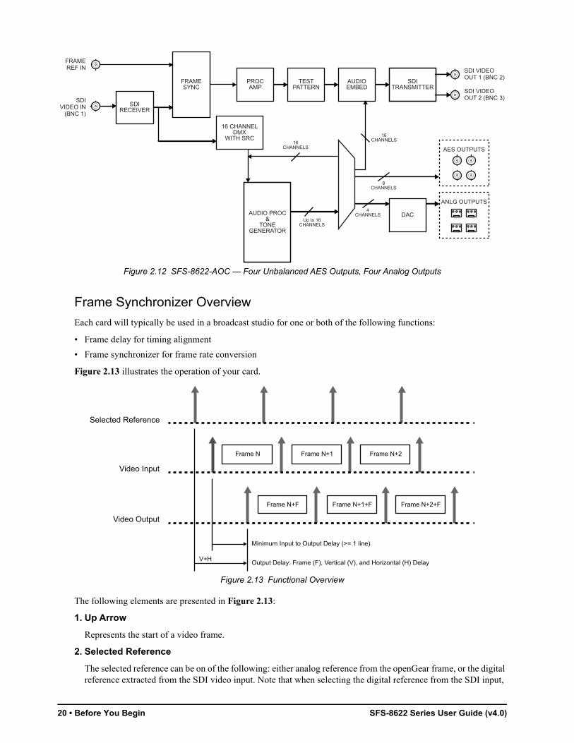
Figure 2.12 SFS-8622-AOC — Four Unbalanced AES Outputs, Four Analog Outputs
Frame Synchronizer Overview
Each card will typically be used in a broadcast studio for one or both of the following functions:
• Frame delay for timing alignment
• Frame synchronizer for frame rate conversion
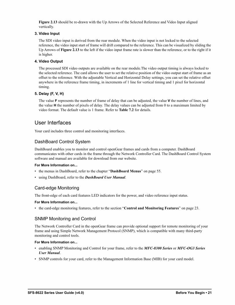
Figure 2.13 illustrates the operation of your card.
Figure 2.13 Functional Overview
The following elements are presented in Figure 2.13:
1. Up Arrow
Represents the start of a video frame.
2. Selected Reference
The selected reference can be on of the following: either analog reference from the openGear frame, or the digital reference extracted from the SDI video input. Note that when selecting the digital reference from the SDI input,
SDIRECEIVER
SDIVIDEO IN
(BNC 1)
PROCAMP
TESTPATTERN
SDITRANSMITTER
AUDIOEMBED
FRAMESYNC
SDI VIDEOOUT 1 (BNC 2)
SDI VIDEOOUT 2 (BNC 3)
16 CHANNELDMX
WITH SRC16
CHANNELS
16CHANNELS
Up to 16CHANNELS
AUDIO PROC&
TONEGENERATOR
AES OUTPUTS
ANLG OUTPUTS
8CHANNELS
FRAMEREF IN
4CHANNELS DAC
Frame N Frame N+1 Frame N+2
Frame N+F Frame N+1+F Frame N+2+F
SFS-8622 Series User Guide (v4.0) Before You Begin • 21
Figure 2.13 should be re-drawn with the Up Arrows of the Selected Reference and Video Input aligned vertically.
3. Video Input
The SDI video input is derived from the rear module. When the video input is not locked to the selected reference, the video input start of frame will drift compared to the reference. This can be visualized by sliding the Up Arrows of Figure 2.13 to the left if the video input frame rate is slower than the reference, or to the right if it is higher.
4. Video Output
The processed SDI video outputs are available on the rear module.The video output timing is always locked to the selected reference. The card allows the user to set the relative position of the video output start of frame as an offset to the reference. With the adjustable Vertical and Horizontal Delay settings, you can set the relative offset anywhere in the reference frame timing, in increments of 1 line for vertical timing and 1 pixel for horizontal timing.
5. Delay (F, V, H)
The value F represents the number of frame of delay that can be adjusted, the value V the number of lines, and the value H the number of pixels of delay. The delay values can be adjusted from 0 to a maximum limited by video format. The default value is 1 frame. Refer to Table 7.2 for details.
User Interfaces
Your card includes three control and monitoring interfaces.
DashBoard Control System
DashBoard enables you to monitor and control openGear frames and cards from a computer. DashBoard communicates with other cards in the frame through the Network Controller Card. The DashBoard Control System software and manual are available for download from our website.
For More Information on...
• the menus in DashBoard, refer to the chapter “DashBoard Menus” on page 55.
• using DashBoard, refer to the DashBoard User Manual.
Card-edge Monitoring
The front-edge of each card features LED indicators for the power, and video reference input status.
For More Information on...
• the card-edge monitoring features, refer to the section “Control and Monitoring Features” on page 23.
SNMP Monitoring and Control
The Network Controller Card in the openGear frame can provide optional support for remote monitoring of your frame and using Simple Network Management Protocol (SNMP), which is compatible with many third-party monitoring and control tools.
For More Information on...
• enabling SNMP Monitoring and Control for your frame, refer to the MFC-8300 Series or MFC-OG3 Series User Manual.
• SNMP controls for your card, refer to the Management Information Base (MIB) for your card model.

22 • Before You Begin SFS-8622 Series User Guide (v4.0)

SFS-8622 Series User Guide (v4.0) Hardware Overview • 23
Hardware OverviewThis chapter provides a summary of the card components including the card-edge LEDs.
Card Overview
This section provides a general overview of the card components.
Figure 3.1 Card Components — SFS-8622-A
1. Bootload Button (SW1)
SW1 is used for factory service in the unlikely event of a complete card failure. Do not press this button unless instructed to do so by Ross Technical Support personnel.
For More Information on...
• the LEDs located on the card-edge, refer to the section “Control and Monitoring Features” on page 23.
Control and Monitoring Features
This section provides information on the card-edge LEDs. Refer to Figure 3.2 for the location of the LEDs.
Figure 3.2 Card-edge LEDs
1
OK/ERROR LED
VIDEO OK LEDREF OK LED
AES 1 OK LEDAES 2 OK LEDAES 3 OK LEDAES 4 OK LEDAES 5 OK LED
AES 6 OK LEDAES 7 OK LEDAES 8 OK LED
Bootload Button (SW1)

24 • Hardware Overview SFS-8622 Series User Guide (v4.0)
Status and Selection LEDs
Basic LED displays and descriptions are provided in Table 3.1.
Table 3.1 Card-edge LEDs
LED Color Display and Description
OK/ERROR Green When lit green, this LED indicates that the card is functioning normal and that no anomalies have been detected. The following conditions must be satisfied:
• a valid input signal is present
• a valid reference signal is present when a reference is required, and that the reference standard matches the input standard.
Flashing Green When flashing green, this LED indicates the bootloader is waiting for a software upload.
Flashing Green and Orange
When lit green with flashing orange, this LED indicates there is a signal error such as a missing or invalid input or reference.
Red When powering on, this LED will be lit red momentarily as the card boots. If lit red for more than 3 seconds, this LED indicates the card is not operational.
When lit red, this LED indicates the card is not operational.
Off When off, this LED indicates there is no power to the card.
VIDEO OK Green When lit, this LED indicates that the video input is valid.
Flashing Green When flashing, this LED indicates that video is present, but the input format is unsupported.
Off When unlit, this LED indicates the absence of an input signal.
REF OK Green When lit green, this LED indicates a valid reference signal.
Off When unlit, this LED indicates that a reference signal is not present, or is not supported.
AES # Yellow SFS-8622-A, SFS-8622-B, SFS-8622-AIC, SFS-8622-AOC— When lit, an LED indicates a valid signal is detected on the corresponding AES input.
SFS-8622-IC — When lit, an LED indicates a valid and not silent signal is detected on the corresponding analog input.
SFS-8622-OC — These LEDs are not implemented.
Off SFS-8622-A, SFS-8622-B, SFS-8622-AIC, SFS-8622-AOC— When unlit, an LED indicates that a valid signal is not detected on the corresponding AES input.
SFS-8622-IC — When unlit, an LED indicates the corresponding analog signal is silent.
SFS-8622-OC — These LEDs are not implemented.

SFS-8622 Series User Guide (v4.0) Physical Installation • 25
Physical InstallationThis chapter provides instructions for installing a rear module, and installing a card into an openGear frame.
Before You Begin
Before proceeding with the instructions in this chapter, ensure that your openGear frame is properly installed according to the instructions in its manual.
Static Discharge
Throughout this chapter, please heed the following cautionary note:
Unpacking
Unpack each card you received from the shipping container and ensure that all items are included. If any items are missing or damaged, contact your sales representative or Ross Video directly.
Supported Rear Modules
Table 4.1 summarizes the required rear modules based on the card type. Each rear module occupies two slots in the openGear frame and accommodates one card.
Installing a Rear Module
This section outlines how to install a rear module and card in an openGear frame.
The SFS-8622 series cards are not supported in the DFR-8310 series frames.
If the rear module is already installed, proceed to the section Refer to the section “Installing a Card” on page 26.
To install a rear module in your openGear frame
1. Locate the card frame slots on the rear of the frame. Each rear module requires two slots.
2. Remove the Blank Plate from the slot you have chosen for the card installation.
3. Install the bottom of the rear module in the Module Seating Slot at the base of the frame’s back plane.
ESD Susceptibility — Static discharge can cause serious damage to sensitive semiconductor devices. Avoid handling circuit boards in high static environments such as carpeted areas and when synthetic fiber clothing is worn. Always exercise proper grounding precautions when working on circuit boards and related equipment.
Table 4.1 Supported Rear Modules
Model Required Rear Module
SFS-8622-A 8320AR-041
SFS-8622-B 8320AR-062
SFS-8622-IC 8320AR-062
SFS-8622-OC 8320AR-062
SFS-8622-AIC 8320AR-058
SFS-8622-AOC 8320AR-058

26 • Physical Installation SFS-8622 Series User Guide (v4.0)
4. Align the top hole of the rear module with the screw on the top-edge of the frame back plane.
5. Using a Phillips screwdriver and the supplied screw, fasten the rear module to the back plane of the frame. Do not over tighten.
6. Ensure proper frame cooling and ventilation by having all rear frame slots covered with rear modules or blank plates.
Installing a Card
This section outlines how to install a card in an openGear frame. If the card is to be installed in any compatible frame other than a Ross Video product, refer to the frame manufacturer’s manual for specific instructions.
Each rear module occupies two slots but accommodates one card in the openGear frame.
To install the card in an openGear frame
1. Locate the Rear Module you installed in the procedure Refer to the section “Installing a Rear Module” on page 25.
2. Hold the card by the edges and carefully align the card-edges with the slots in the frame.
3. Fully insert the card into the frame until the rear connection plus is properly seated in the Rear Module.
4. Verify whether your Rear Module Label is self-adhesive by checking the back of the label for a thin wax sheet. You must remove the wax sheet before affixing the label.
5. Affix the supplied Rear Module Label to the BNC area of the Rear Module.
Screw Hole
Module Seating Slots

SFS-8622 Series User Guide (v4.0) Cabling • 27
CablingThis chapter provides cabling designations for each card, operating mode, and supported rear module.
The number of inputs and outputs is dependent on the selection made in the AES I/O Config menu.
SFS-8622-A Cabling
This section illustrates the cabling designations for the SFS-8622-A.
AES inputs and outputs are configured in groups of three.
Six AES Inputs Only
Figure 5.1 illustrates the cabling designations for one SDI input, two SDI outputs, and six AES-3id 75ohm unbalanced inputs. The AES I/O Config is set to 6 in, 0 out.
Figure 5.1 Cable Connections for the SFS-8622-A
Six AES Outputs Only
Figure 5.2 illustrates the cabling designations for one SDI input, two SDI outputs, and six AES-3id 75ohm unbalanced outputs. The AES I/O Config is set to 0 in, 6 out.
Figure 5.2 Cable Connections for the SFS-8622-A
SDI IN
SDI OUT 2
AES IN 1
AES IN 2
AES IN 3
AES IN 4
AES IN 5
AES IN 6
SDI OUT 1
Not Used
SDI IN
SDI OUT 2
AES OUT 1
AES OUT 2
AES OUT 3
AES OUT 4
AES OUT 5
AES OUT 6
SDI OUT 1
Not Used
28 • Cabling SFS-8622 Series User Guide (v4.0)
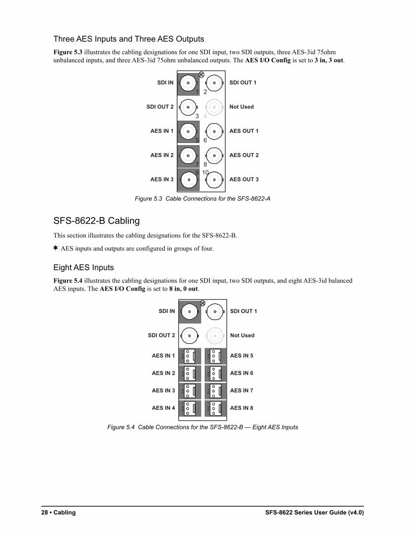
Three AES Inputs and Three AES Outputs
Figure 5.3 illustrates the cabling designations for one SDI input, two SDI outputs, three AES-3id 75ohm unbalanced inputs, and three AES-3id 75ohm unbalanced outputs. The AES I/O Config is set to 3 in, 3 out.
Figure 5.3 Cable Connections for the SFS-8622-A
SFS-8622-B Cabling
This section illustrates the cabling designations for the SFS-8622-B.
AES inputs and outputs are configured in groups of four.
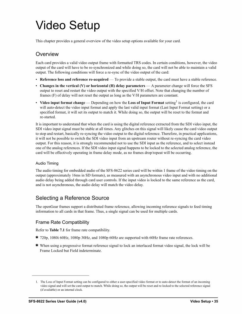
Eight AES Inputs
Figure 5.4 illustrates the cabling designations for one SDI input, two SDI outputs, and eight AES-3id balanced AES inputs. The AES I/O Config is set to 8 in, 0 out.
Figure 5.4 Cable Connections for the SFS-8622-B — Eight AES Inputs
SDI IN
SDI OUT 2
AES IN 1
AES IN 2
AES IN 3
AES OUT 1
AES OUT 2
AES OUT 3
SDI OUT 1
Not Used
AES IN 5
AES IN 2 AES IN 6
AES IN 7AES IN 3
AES IN 8AES IN 4
SDI OUT 1
Not Used
AES IN 1
SDI IN
SDI OUT 2
- G
nd
+-
Gnd
+
- G
nd
+-
Gnd
+
- G
nd
+-
Gnd
+
- G
nd
+-
Gnd
+

SFS-8622 Series User Guide (v4.0) Cabling • 29
Eight AES Outputs
Figure 5.5 illustrates the cabling designations for one SDI input, two SDI outputs, and eight AES-3id balanced AES outputs. The AES I/O Config is set to 0 in, 8 out.
Figure 5.5 Cable Connections for the SFS-8622-B — Eight AES Outputs
Four AES Inputs and Four AES Outputs
Figure 5.6 illustrates the cabling designations for one SDI input, two SDI outputs, four AES-3id balanced AES inputs, and four AES-3id balanced AES outputs. The AES I/O Config is set to 4 in, 4 out.
Figure 5.6 Cable Connections for the SFS-8622-B — Four AES Inputs, Four AES Outputs
AES OUT 5
AES OUT 2 AES OUT 6
AES OUT 7AES OUT 3
AES OUT 8AES OUT 4
SDI OUT 1
Not Used
AES OUT 1
SDI IN
SDI OUT 2
- G
nd
+-
Gnd
+
- G
nd
+-
Gnd
+
- G
nd
+-
Gnd
+
- G
nd
+-
Gnd
+
AES OUT 1
AES IN 2 AES OUT 2
AES OUT 3AES IN 3
AES OUT 4AES IN 4
SDI OUT 1
Not Used
AES IN 1
SDI IN
SDI OUT 2
- G
nd
+-
Gnd
+
- G
nd
+-
Gnd
+
- G
nd
+-
Gnd
+
- G
nd
+-
Gnd
+

30 • Cabling SFS-8622 Series User Guide (v4.0)
SFS-8622-IC Cabling
Figure 5.7 illustrates the cabling designations for the SFS-8622-IC and the 8320AR-062 Full Rear Module. This rear module provides one SDI input, two SDI outputs, and eight analog inputs.
Figure 5.7 Cable Connections for the SFS-8622-IC
SFS-8622-OC CablingFigure 5.8 illustrates the cabling designations for the SFS-8622-OC and the 8320AR-062 Full Rear Module. This rear module provides one SDI input, two SDI outputs, and eight analog outputs.
Figure 5.8 Cable Connections for the SFS-8622-OC
ANLG IN 5
ANLG IN 2 ANLG IN 6
ANLG IN 7ANLG IN 3
ANLG IN 8ANLG IN 4
SDI OUT 1
Not Used
ANLG IN 1
SDI IN
SDI OUT 2
- G
nd
+-
Gnd
+
- G
nd
+-
Gnd
+
- G
nd
+-
Gnd
+
- G
nd
+-
Gnd
+
ANLG OUT 5
ANLG OUT 2 ANLG OUT 6
ANLG OUT 7ANLG OUT 3
ANLG OUT 8ANLG OUT 4
SDI OUT 1
Not Used
ANLG OUT 1
SDI IN
SDI OUT 2
- G
nd
+-
Gnd
+
- G
nd
+-
Gnd
+
- G
nd
+-
Gnd
+
- G
nd
+-
Gnd
+

SFS-8622 Series User Guide (v4.0) Cabling • 31
SFS-8622-AIC Cabling
This section illustrates the cabling designations for the SFS-8622-AIC.
AES inputs and outputs are configured in groups of four.
Four AES Inputs and Four Analog Inputs
Figure 5.9 illustrates the cabling designations for one SDI input, two SDI outputs, four AES-3id unbalanced inputs, and four analog balanced inputs. The AES I/O Config is set to 4 in, 0 out.
Figure 5.9 Cable Connections for the SFS-8622-AIC — Four Analog Inputs, Four AES Inputs
Four Analog Inputs and Four AES Outputs
Figure 5.10 illustrates the cabling designations for one SDI input, two SDI outputs, four analog balanced inputs, and four AES-3id unbalanced outputs. The AES I/O Config is set to 0 in, 4 out.
Figure 5.10 Cable Connections for the SFS-8622-AIC — Four Analog Inputs, Four AES Outputs
AES IN 2
ANLG IN 2
AES IN 3ANLG IN 3
AES IN 4ANLG IN 4
SDI OUT 1
AES IN 1
ANLG IN 1
SDI IN
SDI OUT 2
- G
nd
+-
Gnd
+
- G
nd
+-
Gnd
+
AES OUT 2
ANLG IN 2
AES OUT 3ANLG IN 3
AES OUT 4ANLG IN 4
SDI OUT 1
AES OUT 1
ANLG IN 1
SDI IN
SDI OUT 2
- G
nd
+-
Gnd
+
- G
nd
+-
Gnd
+

32 • Cabling SFS-8622 Series User Guide (v4.0)
SFS-8622-AOC Cabling
This section illustrates the cabling designations for the SFS-8622-AOC.
AES inputs and outputs are configured in groups of four.
Four AES Inputs and Four Analog Outputs
Figure 5.11 illustrates the cabling designations for one SDI input, two SDI outputs, four AES-3id 75ohm unbalanced inputs, and four analog balanced outputs. The AES I/O Config is set to 4 in, 0 out.
Figure 5.11 Cable Connections for the SFS-8622-AOC — Four AES Inputs, Four Analog Outputs
Four AES Outputs and Four Analog Outputs
Figure 5.12 illustrates the cabling designations for one SDI input, two SDI outputs, four AES-3id 75ohm unbalanced outputs, and four analog balanced outputs. The AES I/O Config is set to 0 in, 4 out.
Figure 5.12 Cable Connections for the SFS-8622-AOC — Four Analog Outputs, Four AES Outputs
AES IN 2
ANLG OUT 2
AES IN 3ANLG OUT 3
AES IN 4ANLG OUT 4
SDI OUT 1
AES IN 1
ANLG OUT 1
SDI IN
SDI OUT 2
- G
nd
+-
Gnd
+
- G
nd
+-
Gnd
+
AES OUT 2
ANLG OUT 2
AES OUT 3ANLG OUT 3
AES OUT 4ANLG OUT 4
SDI OUT 1
AES OUT 1
ANLG OUT 1
SDI IN
SDI OUT 2
- G
nd
+-
Gnd
+
- G
nd
+-
Gnd
+

SFS-8622 Series User Guide (v4.0) Using DashBoard • 33
Using DashBoardThe DashBoard Control System enables you to monitor and control openGear frames and cards from a computer. DashBoard communicates with cards in the openGear frame through the Network Controller Card. This controller card is required in order to use DashBoard to monitor the SFS-8622.
Before You Begin
Before proceeding, ensure that DashBoard software version 6.2.0 or higher is installed on a PC connected to your facility network. The DashBoard software and user manual are available from the Ross Video website.
For More Information on...
• using DashBoard, refer to the DashBoard User Manual.
Accessing the SFS-8622 in DashBoard
Ensure that the openGear frame with the SFS-8622 card(s) is displayed in the Tree View located on the left-side of the DashBoard window. It may take 30 seconds or more to update the Tree View. Consult the MFC-OG3 Series User Manual and DashBoard User Manual should the Tree View not display the SFS-8622 node.
To launch DashBoard
1. Ensure that you are running DashBoard software version 8.4.0 or higher.
2. Launch DashBoard by double-clicking its icon on your desktop.
To access the SFS-8622 in DashBoard
1. From the Tree View, expand the node for the openGear frame your cards are installed in.
A list of cards installed in the frame displays.
2. Double-click the node for a card to display its menus in the right-side of the DashBoard window.

34 • Using DashBoard SFS-8622 Series User Guide (v4.0)
SFS-8622 Series User Guide (v4.0) Video Setup • 35
Video SetupThis chapter provides a general overview of the video setup options available for your card.
Overview
Each card provides a valid video output frame with formatted TRS codes. In certain conditions, however, the video output of the card will have to be re-synchronized and while doing so, the card will not be able to maintain a valid output. The following conditions will force a re-sync of the video output of the card:
• Reference loss and reference re-acquired — To provide a stable output, the card must have a stable reference.
• Changes in the vertical (V) or horizontal (H) delay parameters — A parameter change will force the SFS output to reset and restart the video output with the specified V/H offset. Note that changing the number of frames (F) of delay will not reset the output as long as the V/H parameters are constant.
• Video input format change — Depending on how the Loss of Input Format setting1 is configured, the card will auto-detect the video input format and apply the last valid input format (Last Input Format setting) or a specified format, it will set its output to match it. While doing so, the output will be reset to the format and re-started.
It is important to understand that when the card is using the digital reference extracted from the SDI video input, the SDI video input signal must be stable at all times. Any glitches on this signal will likely cause the card video output to stop and restart, basically re-syncing the video output to the digital reference. Therefore, in practical applications, it will not be possible to switch the SDI video input from an upstream router without re-syncing the card video output. For this reason, it is strongly recommended not to use the SDI input as the reference, and to select instead one of the analog references. If the SDI video input signal happens to be locked to the selected analog reference, the card will be effectively operating in frame delay mode, as no frames drop/repeat will be occurring.
Audio Timing
The audio timing for embedded audio of the SFS-8622 series card will be within 1 frame of the video timing on the output (approximately 16ms in SD formats), as measured with an asynchronous video input and with no additional audio delay being added through card user controls. If the input video is locked to the same reference as the card, and is not asynchronous, the audio delay will match the video delay.
Selecting a Reference Source
The openGear frames support a distributed frame reference, allowing incoming reference signals to feed timing information to all cards in that frame. Thus, a single signal can be used for multiple cards.
Frame Rate Compatibility
Refer to Table 7.1 for frame rate compatibility.
720p, 1080i 60Hz, 1080p 30Hz, and 1080p 60Hz are supported with 60Hz frame rate references.
When using a progressive format reference signal to lock an interlaced format video signal, the lock will be Frame Locked but Field indeterminate.
1. The Loss of Input Format setting can be configured to either a user-specified video format or to auto-detect the format of an incoming video signal and will set the card output to match. While doing so, the output will be reset and re-locked to the selected reference signal (if available) or an internal clock.

36 • Video Setup SFS-8622 Series User Guide (v4.0)
Selecting a Reference Source
If the Reference source is set to Frame 1, or Frame 2, if the reference present is valid, and if the frame timing settings is greater than or equal to 1, the card is automatically set to Frame Sync mode. If a valid reference is selected, and then removed, the card will remain in Frame Sync mode but will flywheel. This means that the card will be dropping or repeating the display of some video input frames as necessary to keep the input to output delay within the specified range of F to F+1 frames delay. The frame drop/repeat occurs whenever the video input frame start point crosses over the video output frame start point.
The card has built-in hysteresis to avoid visible artifacts if the input and output timing alignment oscillates around the drop/repeat cross-over point.
To select a reference source for the card
1. From the Device View in DashBoard, select the Setup tab.
Table 7.1 Output/Reference Compatibility
Video Format
Reference Format
480
i 59.
94 (
NT
SC
)
108
0i 5
9.94
Hz
720
p 5
9.94
Hz
576
i 50
Hz
(PA
L)
108
0i 5
0Hz
720
p 5
0Hz
108
0p
23.
98H
z
1080
psf
23.
98H
z
1080
p 2
4Hz
108
0p
sf 2
4Hz
480i 59.94
720p 59.94Hz
1080i 59.94Hz
1080p 59.94Hz
1080p 29.97Hz
576i 50Hz
720p 50Hz
1080i 50Hz
1080p 50Hz
1080p 25Hz
1080psf 24Hz
1080psf 23.98Hz
1080p 23.98Hz

SFS-8622 Series User Guide (v4.0) Video Setup • 37
2. Select a reference input from the Reference Setup area. Refer to Table 10.4 on page 58 for a list of options.
If you are using Frame 1 or Frame 2 as the reference, the card input video frame rate must match the reference frame rate.
Adding a Delay
The card is suited to solve system timing problems where the difference in delay is constant between two paths. An example of this would be a situation where a downstream switcher needs to have clean switches between the output of a production switcher and some of the same input sources fed to the production switcher. The card cannot completely correct badly missed switches, signal drops, or similar issues unless the user has chosen to add at least 1 frame of delay. Note that the Input Timing field of the Signal tab reports the input video timing with respect to the selected analog reference signal.
The delay values can be adjusted from 0 to a maximum limit that depends on the video format. Refer to Table 7.2 for the range of available delay values.
Table 7.2 Delay Range
Format
Range of Values
Horizontal Delay (pixels)
Vertical Delay (lines)
Frame Delay (frames)
480i 59.94 0-857 0-524 0-120
576i 50 0-863 0-624 0-100
1080p 60 0-2199 0-1124 0-36
1080p 59.94 0-2199 0-1124 0-36
1080p 50 0-2639 0-1124 0-30
1080i 60 0-2199 0-1124 0-36
1080i 59.94 0-2199 0-1124 0-36
1080i 50 0-2639 0-1124 0-30
1080p 30 0-2199 0-1124 0-36
1080p 29.97 0-2199 0-1124 0-36
1080p 25 0-2639 0-1124 0-30
38 • Video Setup SFS-8622 Series User Guide (v4.0)
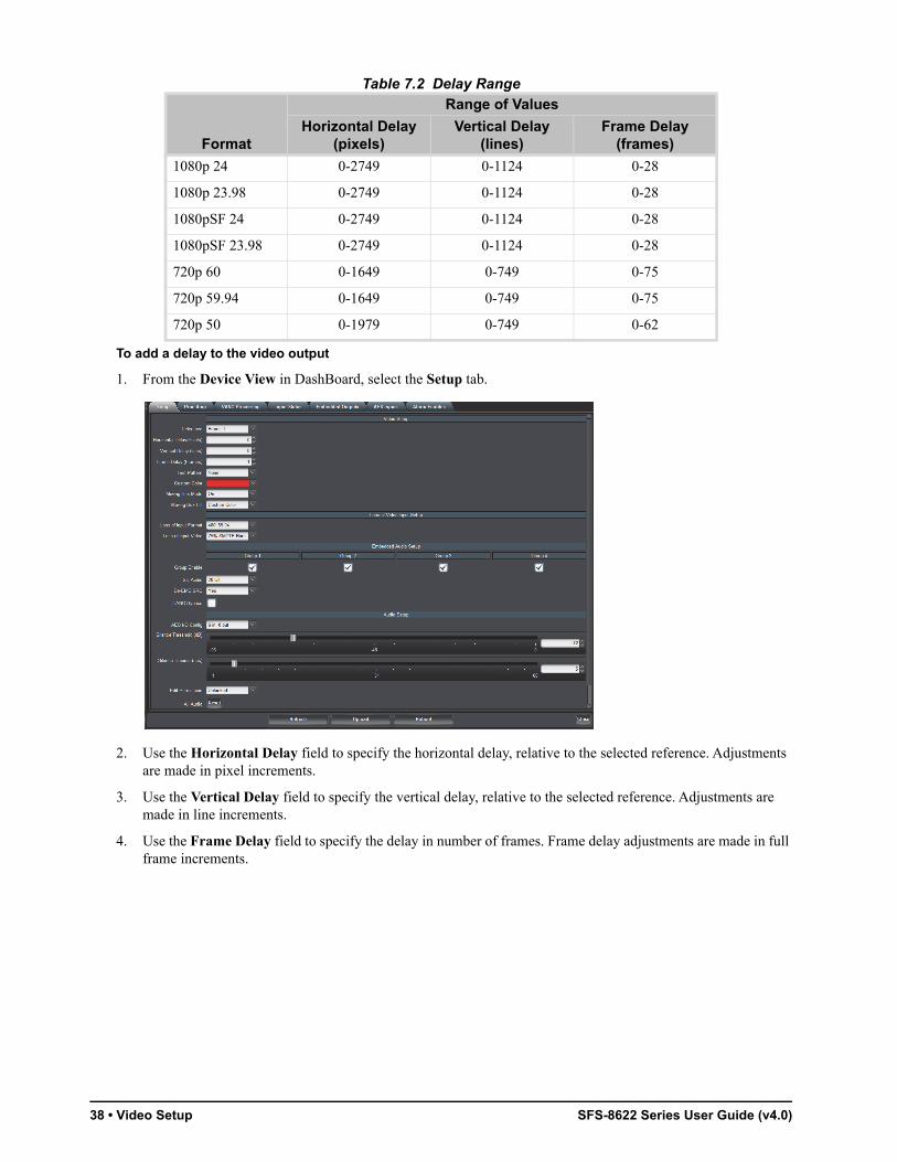
To add a delay to the video output
1. From the Device View in DashBoard, select the Setup tab.
2. Use the Horizontal Delay field to specify the horizontal delay, relative to the selected reference. Adjustments are made in pixel increments.
3. Use the Vertical Delay field to specify the vertical delay, relative to the selected reference. Adjustments are made in line increments.
4. Use the Frame Delay field to specify the delay in number of frames. Frame delay adjustments are made in full frame increments.
1080p 24 0-2749 0-1124 0-28
1080p 23.98 0-2749 0-1124 0-28
1080pSF 24 0-2749 0-1124 0-28
1080pSF 23.98 0-2749 0-1124 0-28
720p 60 0-1649 0-749 0-75
720p 59.94 0-1649 0-749 0-75
720p 50 0-1979 0-749 0-62
Table 7.2 Delay Range
Format
Range of Values
Horizontal Delay (pixels)
Vertical Delay (lines)
Frame Delay (frames)
SFS-8622 Series User Guide (v4.0) Video Setup • 39
Adjusting with Video Proc Amps
The output on the card has a Proc Amp that can adjust the black offset, the video gain, the Cr gain, and the Cb gain.
This section briefly outlines how to adjust the options available in the Proc Amp tab.
For More Information on...
• the options in the Proc Amp tab, refer to Table 10.5.
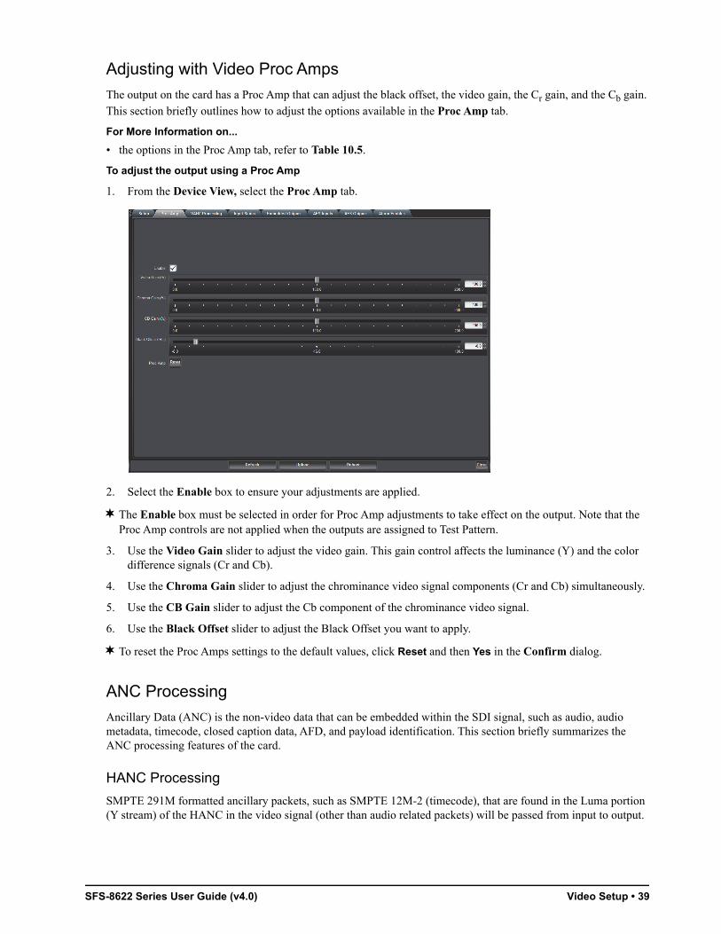
To adjust the output using a Proc Amp
1. From the Device View, select the Proc Amp tab.
2. Select the Enable box to ensure your adjustments are applied.
The Enable box must be selected in order for Proc Amp adjustments to take effect on the output. Note that the Proc Amp controls are not applied when the outputs are assigned to Test Pattern.
3. Use the Video Gain slider to adjust the video gain. This gain control affects the luminance (Y) and the color difference signals (Cr and Cb).
4. Use the Chroma Gain slider to adjust the chrominance video signal components (Cr and Cb) simultaneously.
5. Use the CB Gain slider to adjust the Cb component of the chrominance video signal.
6. Use the Black Offset slider to adjust the Black Offset you want to apply.
To reset the Proc Amps settings to the default values, click Reset and then Yes in the Confirm dialog.
ANC Processing
Ancillary Data (ANC) is the non-video data that can be embedded within the SDI signal, such as audio, audio metadata, timecode, closed caption data, AFD, and payload identification. This section briefly summarizes the ANC processing features of the card.
HANC Processing
SMPTE 291M formatted ancillary packets, such as SMPTE 12M-2 (timecode), that are found in the Luma portion (Y stream) of the HANC in the video signal (other than audio related packets) will be passed from input to output.

40 • Video Setup SFS-8622 Series User Guide (v4.0)
VANC Processing
The card provides options for replacing the full active portion of selected lines of video with black. The VANC Processing tab is divided into separate sub-tabs for each format to provide selection of the lines. This enables you to individually select any combination of lines, from line 1 up to the third line after the active video for the current video format. For interlaced formats, the lines in the two fields are separately configured. Table 7.3 lists the allowable line selections based on format.
To delete the VANC components in a line
1. Display the Device View in DashBoard for the card you wish to configure.
2. Select the VANC Processing tab.
3. Select the sub-tab, located at the bottom of the VANC Processing tab, for the applicable video format.
When using an 1080pSF input signal, select the 1080i sub-tab.
4. In the Line column, locate the line you wish to delete the VANC components for.
Notice for interlaced formats that the Line column on the left lists the lines in Field 1, and the Line column on the right lists the lines in Field 2.
5. To delete the VANC components, select one of the following:
• for a specific line — select Strip for that line. The default for each line is Pass.
• for all lines of a video format — click the Strip button located near the bottom of the applicable sub-tab.
Click Pass to pass the VANC components without modification for all lines in a specific video format.
Selecting a Test Pattern
You can also specify the type of internally generated test pattern to output.
When selecting a test pattern as the Loss of Input Video, the card will output the video in the format that is selected in the Loss of Input Format field.
To select the type of test pattern to output
1. From the Device View in DashBoard, select the Setup tab.
Table 7.3 VANC Processing — Line Selection
Format Field 1 Lines Fields 2 Lines
1080p 1-44 -
1080i 1-23 562-586
720p 1-28 -
576i 1-25 313-338
480i 1-23 264-285

SFS-8622 Series User Guide (v4.0) Video Setup • 41
2. Use the Test Pattern menu to select a pattern to display on the output. Refer to Table 10.4 for a list of options.
3. If you selected Custom Color in step 2, specify the color as outlined in the section “Specifying a Custom Color” on page 42.
Configuring the Moving Box Test Feature
The Moving Box feature enables an overlay in the shape of a box that moves across the screen in a pre-determined pattern.
If Freeze is selected for the Loss of Input Video setting and the input video signal is lost, the Moving Box test feature remains active (the box continues to move across the screen.)
To configure the moving box test feature
1. From the Device View in DashBoard, select the Setup tab.
2. Use the Moving Box menu to specify the fill of the box or disable this feature. Refer to Table 10.4 for details.

42 • Video Setup SFS-8622 Series User Guide (v4.0)
3. If you selected Custom Color in 2, specify the color fill for the box as outlined in the section “Specifying a Custom Color” on page 42.
Specifying the Output During a Loss of Input
The card enables you to specify the output during a loss of input, or during a change of input format. The embedded audio will also go silent if passing from input to output (when another audio is not selected).
To specify the output if the video input is lost
1. From the Device View in DashBoard, select the Setup tab.
2. Use the Loss of Input Format menu to specify the output video format when the card experiences a loss of input. Refer to Table 10.4 for a list of options.
3. Use the Loss of Input Video menu to specify what to output when the card experiences a loss of input. Refer to Table 10.4 for a list of options.
If you selected Freeze, ensure that the Loss of Input Format field is set to the same format as the input video signal or to Last Input Format. If not, the card will not output a Freeze Frame, but a full Field Black image in the format selected in the Loss of Input Format field.
4. If you selected Custom Color in step 3, specify the color to use as outlined in the section “Specifying a Custom Color” on page 42.
Specifying a Custom Color
The card provides an HSL color space to edit the Hue, Saturation, and Luminance levels of a custom color. You can assign this Custom Color as the Test Pattern, the output during a loss of input signal, or as the fill for the Moving Box test feature.
The Transparency menu is not implemented.
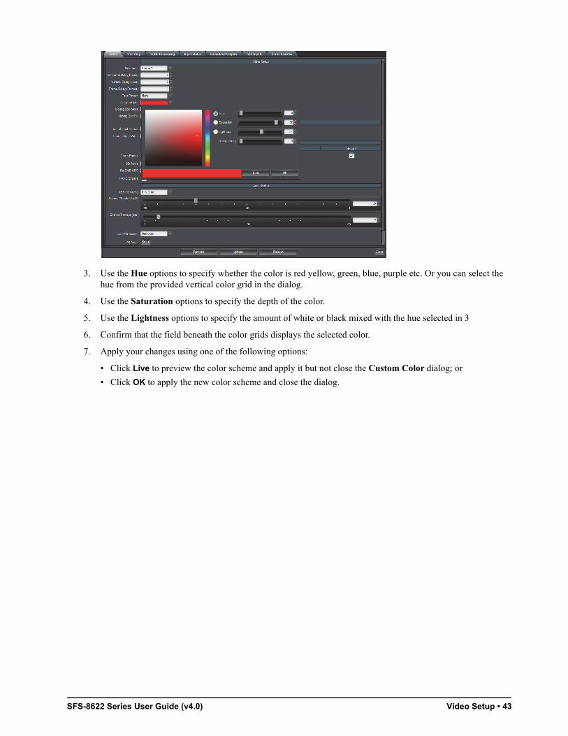
To specify a custom color
1. From the Device View in DashBoard, select the Setup tab.
2. Select the Custom Color menu to display the Custom Color dialog.
SFS-8622 Series User Guide (v4.0) Video Setup • 43
3. Use the Hue options to specify whether the color is red yellow, green, blue, purple etc. Or you can select the hue from the provided vertical color grid in the dialog.
4. Use the Saturation options to specify the depth of the color.
5. Use the Lightness options to specify the amount of white or black mixed with the hue selected in 3
6. Confirm that the field beneath the color grids displays the selected color.
7. Apply your changes using one of the following options:
• Click Live to preview the color scheme and apply it but not close the Custom Color dialog; or
• Click OK to apply the new color scheme and close the dialog.

44 • Video Setup SFS-8622 Series User Guide (v4.0)

SFS-8622 Series User Guide (v4.0) Audio Setup • 45
Audio SetupThis chapter provides a general overview of the options in DashBoard for configuring the audio features of your card.
Selecting an AES Configuration
Depending on the card model, you can configure the number of AES inputs and outputs. Table 1.1 on page 12 outlines the audio mode options for each card model.
For More Information on...
• the menus and parameters available in the AES I/O Config menu of the Setup tab, refer to the section “Setup Tab” on page 58.
• alarm options for AES sources, refer to the section “Alarm Enables Tab” on page 66.
To specify the AES configuration
1. From the Device View, select the Setup tab.
2. Specify the configuration for your card by selecting an option from the AES I/O Config menu.
Changing the AES I/O Config setting will default audio source settings if they become invalid.
3. If you have selected a configuration with AES inputs, proceed to the section “Configuring the AES Inputs” on page 46.
4. If you have selected a configuration with AES outputs, proceed to the section “Configuring the AES Outputs” on page 46.
5. Use the SD Audio menu to specify the type of SD audio to embed. Refer to Table 10.4 on page 58 for a list of options.
The card will detect and indicate async for any audio input that is an asynchronous audio input, or has a sample rate other than 48kHz.
6. Use the De-EMB SRC menu to apply the Sample Rate Converter on all de-embedded audio groups from the input source.
46 • Audio Setup SFS-8622 Series User Guide (v4.0)
When the De-EMB SRC is enabled, the Word Length status field always reports that the audio word length is 24bit.
7. Use the Silence Threshold slider to specify a threshold value for silence. Audio with an amplitude (dBFS) equal to or below this value will be considered silent.
8. Use the Silence Timeout slider to define how long (in seconds) that audio is silent before an alarm is raised in the Audio Status field of the Signal tab.
Configuring the AES Inputs
The rear module accepts synchronous AES audio input streams at 48kHz or any asynchronous AES streams from 32kHz to 96kHz with SRC enabled. Note that SRC should only be used with Pulse Code Modulation (PCM) digital audio and not any form of compressed signal, such as Dolby®.
This section briefly summarizes how to configure the options in the AES Inputs tab when the AES I/O Config is set to include AES inputs.
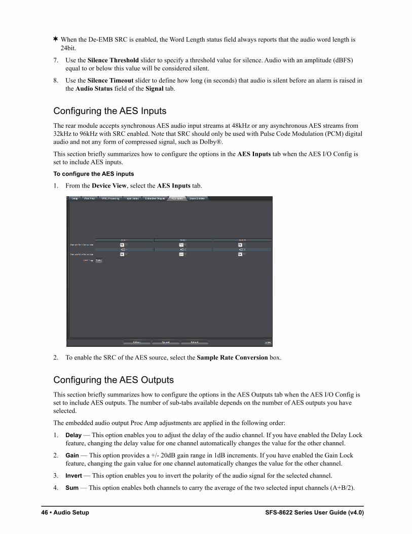
To configure the AES inputs
1. From the Device View, select the AES Inputs tab.
2. To enable the SRC of the AES source, select the Sample Rate Conversion box.
Configuring the AES Outputs
This section briefly summarizes how to configure the options in the AES Outputs tab when the AES I/O Config is set to include AES outputs. The number of sub-tabs available depends on the number of AES outputs you have selected.
The embedded audio output Proc Amp adjustments are applied in the following order:
1. Delay — This option enables you to adjust the delay of the audio channel. If you have enabled the Delay Lock feature, changing the delay value for one channel automatically changes the value for the other channel.
2. Gain — This option provides a +/- 20dB gain range in 1dB increments. If you have enabled the Gain Lock feature, changing the gain value for one channel automatically changes the value for the other channel.
3. Invert — This option enables you to invert the polarity of the audio signal for the selected channel.
4. Sum — This option enables both channels to carry the average of the two selected input channels (A+B/2).

SFS-8622 Series User Guide (v4.0) Audio Setup • 47
To configure the AES outputs
1. From the Device View, select the AES Outputs tab.
2. Use the associated Ch# Source menu to specify the channel source of an AES output.
3. To set the gain for a channel of an AES output, use the associated Ch # Gain slider to select a value between -20dB and 20dB.
4. To set the delay for a channel of an AES output, use the associated Ch # Delay slider to select a value between 0ms and 500ms.
5. To invert a channel of an AES output, select the associated Ch # Invert box.
6. To sum the input (A+B/2) of the AES output, select the Sum box.
7. Repeat steps 2- 6 for each AES output you wish to configure.
Configuring the Analog Inputs
For each analog input, you can adjust the volume of the input analog audio channel in increments of 0.5dB. This enables you to fine tune the balance of each input. You can also choose to have the Audio Status field in DashBoard report when the card detects that a specific analog input is silent.
These options are only available when using an SFS-8622-IC or SFS-8622-AIC.
To trim an analog input
1. From the Device View, select the Analog Inputs tab.

48 • Audio Setup SFS-8622 Series User Guide (v4.0)
2. Use the associated Trim slider for an analog input to select a trim value between -10dB and 10dB.
To configure the analog inputs alarm
1. From the Device View, select the Alarm Enables tab.
2. Locate the Analog Inputs area in the Alarm Enables tab. You may need to scroll down the tab.
3. In the Analog Inputs area, select the box for each input you wish to monitor via the Audio Status field in the Signal tab.
Configuring the Analog Outputs
For each analog output you can assign any of the input audio channels or test tone, add an offset, or invert the input channels. You can also adjust the volume of the analog audio output in increments of 0.5dB, enabling you to fine tune the balance of each output.
These options are only available when using an SFS-8622-OC or SFS-8622-AOC.
To configure an analog output
1. From the Device View, select the Analog Outputs tab.

SFS-8622 Series User Guide (v4.0) Audio Setup • 49
2. Use the associated Source menu to specify the channel source of an analog output.
3. Use the associated Trim slider for an analog output to select a trim value between -10dB and 10dB.
4. To set the delay for a channel of an analog output, use the associated Delay slider to select a value between 0ms and 1000ms.
5. To invert a channel of an analog output, select the associated Invert box.
To configure the analog outputs alarms
1. From the Device View, select the Alarm Enables tab.
2. Locate the Analog Outputs area in the Alarm Enables tab. You may need to scroll down the tab.
3. In the Analog Outputs area, select the Source Missing box for each input you wish to monitor via the Audio Status field in the Signal tab.
An alarm message will display when the select input is not detected by the card.
4. In the Analog Outputs area, select the Source Async box for each input you wish to monitor via the Audio Status field in the Signal tab.
An alarm message will display when the select input is detected as asynchronous to the card’s reference timing.
Embedded Outputs
Your card also includes options for configuring how audio is embedded for SDI video outputs.
For More Information on...
• the embedded audio menus and parameters available in the Setup tab, refer to the section “Setup Tab” on page 58.
• the embedded output settings, refer to the section “Embedded Outputs Tab” on page 63.

50 • Audio Setup SFS-8622 Series User Guide (v4.0)
Setting up Embedded Outputs
Before proceeding, you will need to configure some of the embedded audio options in the Setup tab.
To set up the embedded audio for an output source
1. From the Device View, select the Setup tab.
2. In the Embedded Audio Setup area, select the Enable box for the group(s) to embed in the video output.
3. Use the SD Audio menu to specify the type of SD audio to embed. Refer to Table 10.4 for a list of options.
4. Use the De-EMB SRC menu to apply the Sample Rate Converter on all de-embedded audio groups from the input video source. Refer to the section “Embedding PCM and Non-PCM Signals” on page 51 for details.
When the De-EMB SRC is enabled, the Word Length status field always reports that the audio word length is 24bit.
5. Use the Silence Threshold slider to specify a threshold value for silence. Audio with an amplitude (dBFS) equal to or below this value will be considered silent.
6. Use the Silence Timeout slider to define how long (in seconds) that audio is silent before an alarm is raised in the Audio Status field of the Signal tab.
Configuring the Embedded Output Groups
This section briefly outlines how to configure the options in the Embedded Output tab. Refer to Table 10.9 for details on the options in this tab.
The embedded audio output Proc Amp adjustments are applied in the following order:
1. Delay — This option enables you to adjust the delay of the audio channel. If you have enabled the Delay Lock feature, changing the delay value for one channel automatically changes the value for the other channel.
2. Gain — This option provides a +/- 20dB gain range in 1dB increments. If you have enabled the Gain Lock feature, changing the gain value for one channel automatically changes the value for the other channel.
3. Invert — This option enables you to invert the polarity of the audio signal for the selected channel.
4. Sum — This option enables both channels to carry the average of the two selected input channels (A+B/2).

SFS-8622 Series User Guide (v4.0) Audio Setup • 51
To configure the embedded audio outputs
1. From the Device View, select the Embedded Outputs tab.
2. If required, select the sub-tab that includes the embedded group you wish to configure.
3. To map a channel:
• From the associated Ch # Source menu, select an audio source that is inserted into the embedded group if present. Refer to Table 10.9 on page 63 for a list of options.
• If the selected source is not present on the input video, silence is embedded.
4. To set the gain for an output channel, use the associated Ch # Gain slider to select a value between -20dB and 20dB.
5. To set the delay for an output channel, use the associated Ch # Delay slider to select a value between 0ms and 1000ms.
6. To invert an output channel, select the associated Ch # Invert box.
7. To sum the output channel pair (A+B/2), select the Sum box.
8. Repeat steps 2- 7 for each output channel you wish to configure.
9. Repeat for each group/channel pair you wish to configure.
Embedding PCM and Non-PCM Signals
This section provides additional information on the Processing Amplifiers (Proc Amps) for the audio outputs on the card.
Embedding PCM Signals
Each card can embed PCM audio from two sources: the AES input or from the embedded audio of the source video. Processing also includes embedding channel status data as per Table 12.1.
Embedding Non-PCM Signals
You can configure the card to embed non-PCM signals, such as Dolby® Digital and Dolby® E, using the options available in DashBoard. However, when embedding the non-PCM signal, the A and B channels of the input signal

52 • Audio Setup SFS-8622 Series User Guide (v4.0)
must be embedded on Channels 1 and 2, or Channels 3 and 4 of a given group. For example, you would embed AES1A in Group1Ch1, and AES1B in Group1Ch2.
To embed non-PCM signals
1. Display the Device View in DashBoard for the card you wish to configure.
2. Select the AES Inputs tab.
3. Set the Sample Rate Conversion to Off for the required AES or embedded source.
4. Select the Embedded Outputs tab.
5. In the Embedded Outputs tab, select the sub-tab for the output group that you wish to configure.
6. Clear the applicable Sum box to disable the channel summing.
7. Set the applicable Ch # Gain to 0.
8. Clear the applicable Ch # Invert box to disable inverting on the channel.
9. Ensure that the Delay values of the channels match.

SFS-8622 Series User Guide (v4.0) Software Upgrades • 53
Software UpgradesThis section provides instructions for upgrading the software for your card using the DashBoard Control System.
To upload software to the card
1. Contact Ross Technical Support for the latest software version file.
2. In DashBoard, double-click the card status indicator in the Basic Tree View.
3. From the Device tab, click Upload to display the Select File for upload dialog box.
4. Navigate to the *.bin upload file you wish to upload. DashBoard automatically selects the last directory that you loaded from.
5. Click Open to display a confirmation dialog box. This dialog box displays the selected upload file name, type, size, and the file creation date.
6. From the Confirmation dialog box, select one of the following:
• Cancel — Select this option to cancel the upload of the file and return to the Device View.
• Continue — Select this option to upload the file. While uploading, an Uploading Progress dialog box opens.
Clicking the Cancel button while uploading will leave the card in an invalid state. Do not click Cancel unless the uploading progress has stopped completely for 60 seconds or more. If upload fails, repeat the upload process from DashBoard. If the upload process fails again, refer to the section “Bootload Button” on page 75.
7. Monitor the upgrade progress bar displayed in DashBoard while the software is upgraded on your card.
8. To complete the upgrade process, you must reboot the card as follows:
a. From the Device tab, click Reboot to reboot card. The reboot process takes up to 30 seconds.
The communications processor of the card requires approximately 30 seconds to re-start and re-establish network communications.
b. The card automatically saves all your settings before starting the reboot process.
c. The status of all the cards in the frame are grayed out until the reboot process is complete.

54 • Software Upgrades SFS-8622 Series User Guide (v4.0)

SFS-8622 Series User Guide (v4.0) DashBoard Menus • 55
DashBoard MenusThis chapter summarize the menus, items, and parameters available from DashBoard for your card. Parameters marked with an asterisk (*) are the factory default values.
Wait 30 seconds after the last setting change to ensure all changes are saved to the non-volatile memory of the card.
Status Tabs
This section summarizes the read-only information displayed in the Status tabs. The fields in the Status tabs vary in severity from green (valid), yellow (caution), to red (alarm). DashBoard reports the most severe alarm for a single field.
Signal Tab
Table 10.1 summarizes the read-only information displayed in the Signal tab.
Table 10.1 Signal Tab Items
Item Parameters Description
General
SDI Status OK A valid SDI signal is detected on the input, the format is supported, and the selected reference signal is supported and compatible
No Input An invalid SDI signal is detected on the input
Incompatible A valid SDI signal is detected on the input, the format is supported but the selected reference format selected is not compatible (e.g. an 480i input with a PAL reference signal)
Non-Sync Video A valid SDI signal is detected on the input, the format is supported, the selected reference format is supported but a reference lock is not occurring
Group Not Present At least one embedded audio group is missing from the valid, supported format SDI input signal
Group Channel Silent
At least one embedded audio channel from the valid, supported SDI input signal has an amplitude at or below the Silence Threshold
Audio Status OK A valid AES signal (PCM or non-PCM) is detected on all the inputs
Source Missing No valid AES signal detected on at least one input
Source Async At least one AES input is non-synchronous relative to the selected reference source on the receiving card
AES Input Silent At least one AES input signal has an amplitude at or below the Silence Threshold
AES Input Not Present
At least one AES input signal is not detected

56 • DashBoard Menus SFS-8622 Series User Guide (v4.0)
Audio Status Analog Input Silent
The analog input signal has an amplitude at or below the Silence Threshold. This message is only available for the SFS-8622-IC.
Analog Input Not Present
The analog input signal is not detected. This message is only available for the SFS-8622-IC.
Group 4 Reduced to 20bit
Reduces Group 4 of the embedded audio to 20bit while the other three groups of embedded audio are 24bit
Reference Status OK Indicates that a valid reference source is present
No Ref - Video The following conditions are occurring:
• Card reference is set to Frame 1 or Frame 2
• A valid reference signal is not present
• Card has gone to Video Timing Mode
No Ref - Free Run First possible error condition:
• Card detects an invalid or absent video signal.
• A valid reference signal is not present.
• The Reference menu is set to Frame 1 or Frame 2.
Second possible error condition:
• Card detects an invalid or absent video signal.
• The Reference menu is set to Video.
Input Format # Indicates the input video format
Reference Format # Indicates the reference video format
Output Format # Indicates the output video format
Input Timing Lines: #, Pixels: # Indicates the timing offset between the video input signal and the reference signal. The unit of measure is lines and pixels with respect to the input video format.
Embedded Audio Status - Group #
PCM Indicates the status of the specified embedded audio group
No Input
PCM-Silent
Non-PCM
Async
Mixeda
Not Present One of the audio channel pairs are not detected
AES Inputs
AES # PCM Indicates the presence of the specified AES input
No Input
AES Input Async
PCM-Silent
Non-PCM
Table 10.1 Signal Tab Items
Item Parameters Description
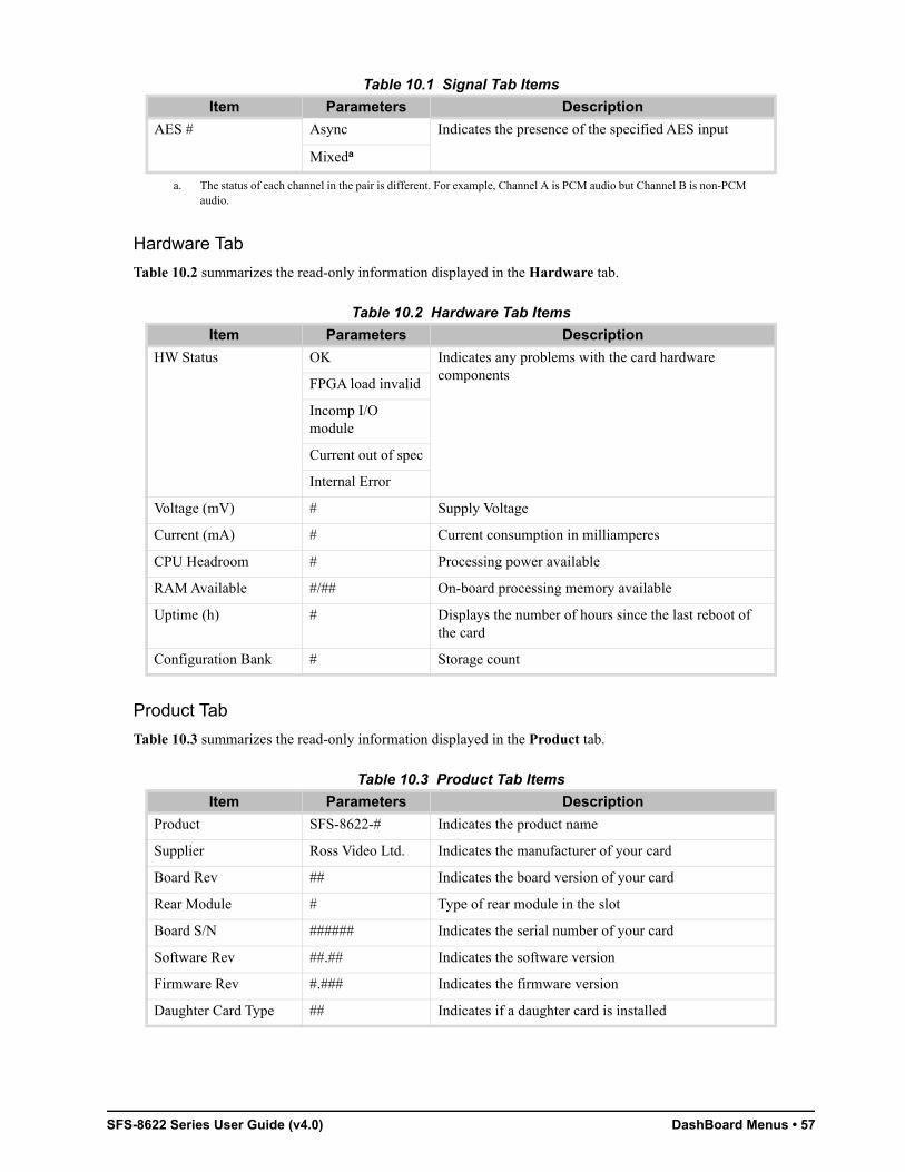
SFS-8622 Series User Guide (v4.0) DashBoard Menus • 57
Hardware Tab
Table 10.2 summarizes the read-only information displayed in the Hardware tab.
Product Tab
Table 10.3 summarizes the read-only information displayed in the Product tab.
AES # Async Indicates the presence of the specified AES input
Mixeda
a. The status of each channel in the pair is different. For example, Channel A is PCM audio but Channel B is non-PCM audio.
Table 10.2 Hardware Tab Items
Item Parameters Description
HW Status OK Indicates any problems with the card hardware components
FPGA load invalid
Incomp I/O module
Current out of spec
Internal Error
Voltage (mV) # Supply Voltage
Current (mA) # Current consumption in milliamperes
CPU Headroom # Processing power available
RAM Available #/## On-board processing memory available
Uptime (h) # Displays the number of hours since the last reboot of the card
Configuration Bank # Storage count
Table 10.3 Product Tab Items
Item Parameters Description
Product SFS-8622-# Indicates the product name
Supplier Ross Video Ltd. Indicates the manufacturer of your card
Board Rev ## Indicates the board version of your card
Rear Module # Type of rear module in the slot
Board S/N ###### Indicates the serial number of your card
Software Rev ##.## Indicates the software version
Firmware Rev #.### Indicates the firmware version
Daughter Card Type ## Indicates if a daughter card is installed
Table 10.1 Signal Tab Items
Item Parameters Description

58 • DashBoard Menus SFS-8622 Series User Guide (v4.0)
Setup Tab
Table 10.4 summarizes the Setup options available in DashBoard.
Table 10.4 Setup Menu Items
Item Parameters Description
Video Setup
Reference Frame 1* Assigns the external analog reference connected to REF 1 port on the openGear frame
Frame 2 Assigns the external analog reference connected to REF 2 port on the openGear frame
Video Reference is taken from the SDI IN video input on the rear module
Horizontal Delay (Pixels)
0* - # Adjusts the horizontal delay with respect to the selected reference. Refer to Table 7.2 on page 37 for value ranges.
Vertical Delay (lines) 0* - # Specifies the vertical delay with respect to the selected reference. Refer to Table 7.2 on page 37 for value ranges.
Frame Delay (Frames) 0 - #a Specifies the number of frames of delay with respect to the selected reference
Test Pattern None* Disables the test pattern feature
Black Specifies the type of test pattern to output.
Note that the test pattern replaces all of the output picture but not the HANC, while the VANC is blanked.
Blue
Custom Color
75% Color Bars
100% Color Bars
75% SMPTE Bars
Matrix Pathological
Luma Ramp
Y/C Ramp
Custom Color # Select this drop down to display a dialog that enables you to configure the Custom Color setting.
This Custom Color will be used as a Test Pattern, Loss of Input, and the Moving Box fill when those menus are set to Custom Color.
Moving Box OFF* Disables this feature
Custom Color An overlay in the shape of a box, filled with the specified custom color, moves across the screen in a pre-determined pattern
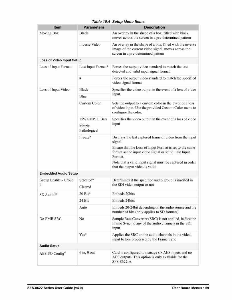
SFS-8622 Series User Guide (v4.0) DashBoard Menus • 59
Moving Box Black An overlay in the shape of a box, filled with black, moves across the screen in a pre-determined pattern
Inverse Video An overlay in the shape of a box, filled with the inverse image of the current video signal, moves across the screen in a pre-determined pattern
Loss of Video Input Setup
Loss of Input Format Last Input Format* Forces the output video standard to match the last detected and valid input signal format.
# Forces the output video standard to match the specified video signal format
Loss of Input Video Black Specifies the video output in the event of a loss of video input.
Blue
Custom Color Sets the output to a custom color in the event of a loss of video input. Use the provided Custom Color menu to configure the color.
75% SMPTE Bars Specifies the video output in the event of a loss of video input
Matrix Pathological
Freeze* Displays the last captured frame of video from the input signal.
Ensure that the Loss of Input Format is set to the same format as the input video signal or set to Last Input Format.
Note that a valid input signal must be captured in order that the output video is valid.
Embedded Audio Setup
Group Enable - Group #
Selected* Determines if the specified audio group is inserted in the SDI video output or not
Cleared
SD Audiobc 20 Bit* Embeds 20bits
24 Bit Embeds 24bits
Auto Embeds 20-24bit depending on the audio source and the number of bits (only applies to SD formats)
De-EMB SRC No Sample Rate Converter (SRC) is not applied, before the Frame Sync, to any of the audio channels in the SDI input
Yes* Applies the SRC on the audio channels in the video input before processed by the Frame Sync
Audio Setup
AES I/O Configd 6 in, 0 out Card is configured to manage six AES inputs and no AES outputs. This option is only available for the SFS-8622-A.
Table 10.4 Setup Menu Items
Item Parameters Description
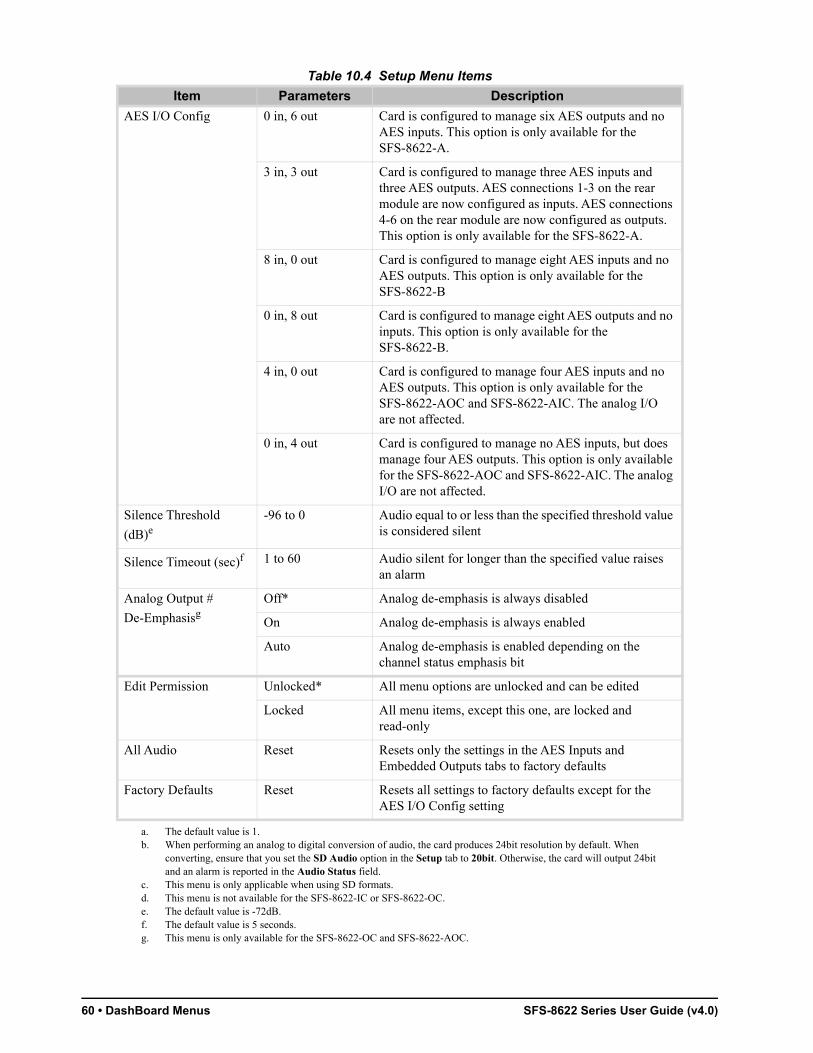
60 • DashBoard Menus SFS-8622 Series User Guide (v4.0)
AES I/O Config 0 in, 6 out Card is configured to manage six AES outputs and no AES inputs. This option is only available for the SFS-8622-A.
3 in, 3 out Card is configured to manage three AES inputs and three AES outputs. AES connections 1-3 on the rear module are now configured as inputs. AES connections 4-6 on the rear module are now configured as outputs. This option is only available for the SFS-8622-A.
8 in, 0 out Card is configured to manage eight AES inputs and no AES outputs. This option is only available for the SFS-8622-B
0 in, 8 out Card is configured to manage eight AES outputs and no inputs. This option is only available for the SFS-8622-B.
4 in, 0 out Card is configured to manage four AES inputs and no AES outputs. This option is only available for the SFS-8622-AOC and SFS-8622-AIC. The analog I/O are not affected.
0 in, 4 out Card is configured to manage no AES inputs, but does manage four AES outputs. This option is only available for the SFS-8622-AOC and SFS-8622-AIC. The analog I/O are not affected.
Silence Threshold
(dB)e-96 to 0 Audio equal to or less than the specified threshold value
is considered silent
Silence Timeout (sec)f 1 to 60 Audio silent for longer than the specified value raises an alarm
Analog Output #
De-EmphasisgOff* Analog de-emphasis is always disabled
On Analog de-emphasis is always enabled
Auto Analog de-emphasis is enabled depending on the channel status emphasis bit
Edit Permission Unlocked* All menu options are unlocked and can be edited
Locked All menu items, except this one, are locked and read-only
All Audio Reset Resets only the settings in the AES Inputs and Embedded Outputs tabs to factory defaults
Factory Defaults Reset Resets all settings to factory defaults except for the AES I/O Config setting
a. The default value is 1.b. When performing an analog to digital conversion of audio, the card produces 24bit resolution by default. When
converting, ensure that you set the SD Audio option in the Setup tab to 20bit. Otherwise, the card will output 24bit and an alarm is reported in the Audio Status field.
c. This menu is only applicable when using SD formats.d. This menu is not available for the SFS-8622-IC or SFS-8622-OC.e. The default value is -72dB.f. The default value is 5 seconds.g. This menu is only available for the SFS-8622-OC and SFS-8622-AOC.
Table 10.4 Setup Menu Items
Item Parameters Description
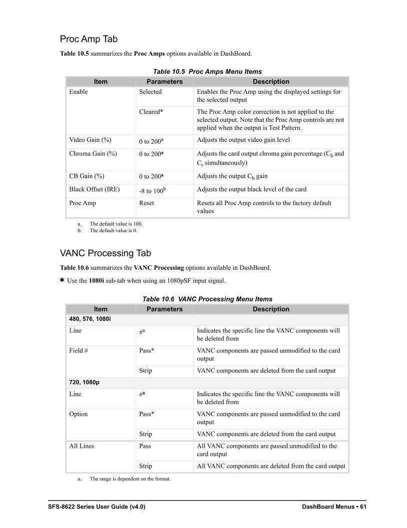
SFS-8622 Series User Guide (v4.0) DashBoard Menus • 61
Proc Amp Tab
Table 10.5 summarizes the Proc Amps options available in DashBoard.
VANC Processing Tab
Table 10.6 summarizes the VANC Processing options available in DashBoard.
Use the 1080i sub-tab when using an 1080pSF input signal.
Table 10.5 Proc Amps Menu Items
Item Parameters Description
Enable Selected Enables the Proc Amp using the displayed settings for the selected output
Cleared* The Proc Amp color correction is not applied to the selected output. Note that the Proc Amp controls are not applied when the output is Test Pattern.
Video Gain (%) 0 to 200a
a. The default value is 100.
Adjusts the output video gain level
Chroma Gain (%) 0 to 200a Adjusts the card output chroma gain percentage (Cb and
Cr simultaneously)
CB Gain (%) 0 to 200a Adjusts the output Cb gain
Black Offset (IRE) -8 to 100b
b. The default value is 0.
Adjusts the output black level of the card
Proc Amp Reset Resets all Proc Amp controls to the factory default values
Table 10.6 VANC Processing Menu Items
Item Parameters Description
480, 576, 1080i
Line #a
a. The range is dependent on the format.
Indicates the specific line the VANC components will be deleted from
Field # Pass* VANC components are passed unmodified to the card output
Strip VANC components are deleted from the card output
720, 1080p
Line #a Indicates the specific line the VANC components will be deleted from
Option Pass* VANC components are passed unmodified to the card output
Strip VANC components are deleted from the card output
All Lines Pass All VANC components are passed unmodified to the card output
Strip All VANC components are deleted from the card output

62 • DashBoard Menus SFS-8622 Series User Guide (v4.0)
Input Status Tab
This section summarizes the sub-tabs available in the Input Status tab.
Video Input & Embedded Tab
Table 10.7 summarizes the read-only information displayed in the Video Input & Embedded sub-tab.
Audio Tab
Table 10.8 summarizes the read-only information displayed in the Audio sub-tab.
Table 10.7 Video Input & Embedded Menu Items
Item Parameters Description
Input Format (read-only)
# Format of the video input
Input Errors (read-only)
# Displays the count of the CRC errors on the video input. This 14bit counter is reset on loss of video, or when the Reset button is selected. The counter is non-latching, and rolls over from maximum count to zero.
• SD formats — displays both active picture and full frame errors
• HD, 3G formats — displays the total count of errors
Error Count Reset Resets the CRC Errors field
Embedded Audio - Group #
Channel # (read-only) PCM Status of each group and channel of embedded audio
No Input
PCM-Silent
Non-PCM
Async
Word Length (read-only)
#bit Word length of the audio in number of bits
Table 10.8 Audio Menu Items
Item Parameters Description
AES #
Ch # Status No Input Displays the status of the specified Channel input
PCM
PCM-silent
Non-PCM
Asynca
Word Length #bit Displays the number of bits of audio

SFS-8622 Series User Guide (v4.0) DashBoard Menus • 63
Embedded Outputs Tab
Table 10.9 summarizes the Embedded Outputs options available in DashBoard.
Groups 1 and 2 are located on the first sub-tab, while Groups 3 and 4 are on the second sub-tab.
Emphasis Present The incoming AES signal is indicating 50/15 or CCiTT J.17 emphasis
Not Present The incoming AES signal is indicating no emphasis or the emphasis is not indicated
Sample Rate # Displays the sample rate of the AES input
a. If the SRC is ON, an async AES signal is processed to be PCM and indicated as such.
Table 10.9 Embedded Outputs Menu Items
Item Parameters Description
GROUP # CH #
Ch # Source Mute Configures the input source for the specified channel that is inserted in to the embedded group (if present)
Group# Ch#*
Analog #a
AES #
#Hz Tone
#kHz Tone
Ch # Gain (dB) -20 to +20b • Adjusts the gain of the specified channel of audio
• Select 0 when using non-PCM audio data
Channel Pair Gain Lock
Selected* Locks the Gain sliders of both channels together. If the values for the two channels are different, that change is maintained when the channels are locked.
Cleared Unlocks the Ch Gain sliders
Ch # Delay (ms) 0* to 1000 Adjusts the delay of the specified audio channel
Channel Pair Delay Lock
Selected* Locks the Ch Delay slider of both channels together. If the values for the two channels are different, that change is maintained when the channels are locked.
Cleared Unlocks the Ch Delay sliders
Ch # Invert Selected Inverts the audio signal of the specified channel
Cleared* • Audio signal of the specified channel is not inverted
• Use for non-PCM audio data
Sum Selected Both channels will carry the average of the two input channels (A+B/2)
Cleared* Disables this feature
Table 10.8 Audio Menu Items
Item Parameters Description

64 • DashBoard Menus SFS-8622 Series User Guide (v4.0)
Analog Inputs Tab
Table 10.10 summarizes the Analog Inputs tab available in DashBoard.
This tab is only available for the SFS-8622-IC and SFS-8622-AIC.
Analog Outputs Tab
Table 10.11 summarizes the Analog Outputs tab available in DashBoard.
This tab is only available for the SFS-8622-OC and SFS-8622-AOC.
Channel Pair Reset Resets the settings for the specified channel pair only to the default values
Groups # Reset Resets the settings for all groups of the specified sub-tab to the default values
a. This option is only available for the SFS-8622-IC and SFS-8622-AIC.b. The default value is 0.
Table 10.10 Analog Inputs Menu Items
Item Parameters Description
Input #
Trim (dB) -10 to 10a
a. The default value is 0.
Adjusts the volume level of the analog signal for the specified input
All CH Reset Resets the trim level to 0dB for all analog inputs
Table 10.11 Analog Outputs Menu Items
Item Parameters Description
Output #
Source Mute Specifies the source for the analog output
Group# Ch#*
AES #
#Hz Tone
#kHz Tone
Trim (dB) -10 to 10a
a. The default value is 0.
Adjusts the volume level of the analog signal for the specified input.
Delay (ms) 0* to 1000 Adjusts the delay of the specified output audio channel
Invert Selected Inverts the audio signal of the specified channel
Cleared* • Audio signal of the specified channel is not inverted
• Use for non-PCM audio data
Analog CH Reset Resets the settings for the specified output
All CH Reset Resets the settings for all channels to the default values
Table 10.9 Embedded Outputs Menu Items
Item Parameters Description
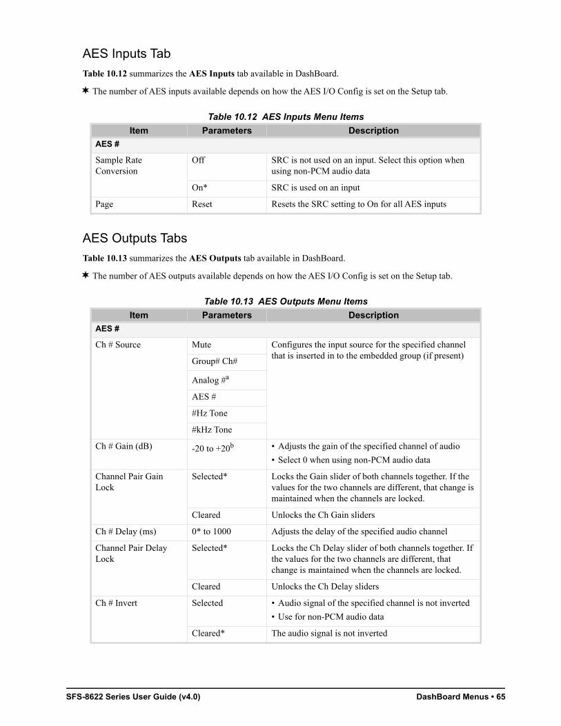
SFS-8622 Series User Guide (v4.0) DashBoard Menus • 65
AES Inputs Tab
Table 10.12 summarizes the AES Inputs tab available in DashBoard.
The number of AES inputs available depends on how the AES I/O Config is set on the Setup tab.
AES Outputs Tabs
Table 10.13 summarizes the AES Outputs tab available in DashBoard.
The number of AES outputs available depends on how the AES I/O Config is set on the Setup tab.
Table 10.12 AES Inputs Menu Items
Item Parameters Description
AES #
Sample Rate Conversion
Off SRC is not used on an input. Select this option when using non-PCM audio data
On* SRC is used on an input
Page Reset Resets the SRC setting to On for all AES inputs
Table 10.13 AES Outputs Menu Items
Item Parameters Description
AES #
Ch # Source Mute Configures the input source for the specified channel that is inserted in to the embedded group (if present)
Group# Ch#
Analog #a
AES #
#Hz Tone
#kHz Tone
Ch # Gain (dB) -20 to +20b • Adjusts the gain of the specified channel of audio
• Select 0 when using non-PCM audio data
Channel Pair Gain Lock
Selected* Locks the Gain slider of both channels together. If the values for the two channels are different, that change is maintained when the channels are locked.
Cleared Unlocks the Ch Gain sliders
Ch # Delay (ms) 0* to 1000 Adjusts the delay of the specified audio channel
Channel Pair Delay Lock
Selected* Locks the Ch Delay slider of both channels together. If the values for the two channels are different, that change is maintained when the channels are locked.
Cleared Unlocks the Ch Delay sliders
Ch # Invert Selected • Audio signal of the specified channel is not inverted
• Use for non-PCM audio data
Cleared* The audio signal is not inverted

66 • DashBoard Menus SFS-8622 Series User Guide (v4.0)
Alarm Enables Tab
Table 10.14 summarizes the Alarm Enables options available in DashBoard.
Sum Selected Both channels will carry the average of the two input channels (A+B/2)
Cleared* Disables this feature
Channel Reset Resets the settings for the selected input to the default values
AES Page Reset Resets the indicated input settings to the default values
a. This option is only available for the SFS-8622-IC and SFS-8622-AIC.b. The default value is 0.
Table 10.14 Alarms Menu Items
Item Parameters Description
Video Input & Reference Alarm
No Input Selected* SDI Status field reports a loss of input
Cleared Disables the alarm
Invalid Input Selected* Input Format field reports when the input video is a format that is not accepted
Cleared Disables the alarm
Incompatible Input Selected* Input Format field reports when the frame rate is not the same as the selected reference input
Cleared Disables the alarm
Unlocked Input Selected* SDI Status field reports if the input becomes unlocked. This alarm can be caused due to a change of reference or video format.
Cleared Disables the alarm
No Reference Selected* Reference Status field reports a loss of input conditions when they occur
Cleared Disables the alarm
Hardware
Incompat Rear Module Selected* HW Status field reports when a rear module is not compatible with the card
Cleared Disables the alarm
Incompat Daughter Card
Selected* This alarm is not implemented. Selecting or clearing this box has no effect.
Cleared
Embedded Input Audio - Group #
Group not present Selected* SDI Status field reports when a group is not present on the input
Cleared Disables the alarm
Table 10.13 AES Outputs Menu Items
Item Parameters Description
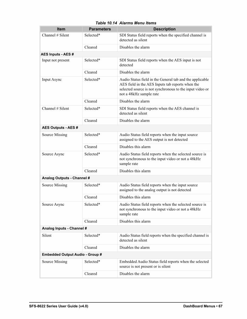
SFS-8622 Series User Guide (v4.0) DashBoard Menus • 67
Channel # Silent Selected* SDI Status field reports when the specified channel is detected as silent
Cleared Disables the alarm
AES Inputs - AES #
Input not present Selected* SDI Status field reports when the AES input is not detected
Cleared Disables the alarm
Input Async Selected* Audio Status field in the General tab and the applicable AES field in the AES Inputs tab reports when the selected source is not synchronous to the input video or not a 48kHz sample rate
Cleared Disables the alarm
Channel # Silent Selected* SDI Status field reports when the AES channel is detected as silent
Cleared Disables the alarm
AES Outputs - AES #
Source Missing Selected* Audio Status field reports when the input source assigned to the AES output is not detected
Cleared Disables this alarm
Source Async Selected* Audio Status field reports when the selected source is not synchronous to the input video or not a 48kHz sample rate
Cleared Disables this alarm
Analog Outputs - Channel #
Source Missing Selected* Audio Status field reports when the input source assigned to the analog output is not detected
Cleared Disables this alarm
Source Async Selected* Audio Status field reports when the selected source is not synchronous to the input video or not a 48kHz sample rate
Cleared Disables this alarm
Analog Inputs - Channel #
Silent Selected* Audio Status field reports when the specified channel is detected as silent
Cleared Disables the alarm
Embedded Output Audio - Group #
Source Missing Selected* Embedded Audio Status field reports when the selected source is not present or is silent
Cleared Disables the alarm
Table 10.14 Alarms Menu Items
Item Parameters Description

68 • DashBoard Menus SFS-8622 Series User Guide (v4.0)
Source Async Selected* Embedded Audio Status field reports when the selected source is not synchronous to the input video, or not a 48kHz sample rate
Cleared Disables the alarm
SD 24Bita Selected* Audio Status field reports when the selected configuration would embed 4 groups of 24bit audio in an SD output. Group 4 is down-sampled to 20bit audio.
Cleared Disables the alarm
All Alarms Set Enables all alarms
All Alarms Clear Disables all alarms
a. When performing an analog to digital conversion of audio, the card produces 24bit resolution by default. When converting, ensure that you set the SD Audio option in the Setup tab to 20bit. Otherwise, the card will output 24bit and an alarm is reported in the Audio Status field.
Table 10.14 Alarms Menu Items
Item Parameters Description

SFS-8622 Series User Guide (v4.0) Technical Specifications • 69
Technical SpecificationsThis chapter provides technical specification details. Note that not all inputs and outputs outlined here are available for all card models
Specifications are subject to change without notice.
For More Information on...
• the inputs and outputs for your card, refer to the Table 1.1 on page 12.
SDI Input
SDI Outputs
Table 11.1 SDI Input Technical Specifications
Parameter Specification
Number of Inputs 1
SDI Data Rates and SMPTE Standards Accommodated
SMPTE 259M, SMPTE 292M, SMPTE 424M
Impedance 75ohm
Return Loss >15dB to 1.5GHz
>10dB to 3.00GHz
Equalization (Belden 1694A cable)
SD: < 450m (1476ft)
HD: < 170m (558ft)
3G: < 100m (328ft)
Connector Type BNC
Table 11.2 SDI Outputs Technical Specifications
Parameter Specification
Number of Outputs 2
SDI Data Rates and SMPTE Standards Accommodated
SMPTE 259M, SMPTE 292M, SMPTE 424M
Impedance 75ohm
Return Loss >15dB to 1.5GHz
>10dB to 3GHz
Signal Level 800mV, +/- 10%
DC Offset <50mV
Rise and Fall Time (20-80%) SD: 600ps typical
HD: 120ps typical
3G: 130ps typical
Overshoot <10%
Connector Type BNC

70 • Technical Specifications SFS-8622 Series User Guide (v4.0)
AES Inputs
AES Outputs
Analog Inputs
Table 11.3 AES Inputs Technical Specifications
Parameter Specification
Standards Accommodated AES-3id-2001, AES3
Impedance 75ohm
Minimum Input 50mV p-p
Maximum Input 2.5V p-p @ 48kHz
1.5V p-p @ 96kHz
Minimum Audio Delay SRC on: 1.35mS
SRC off: 0.37mS
Sampling Rate 48kHz compliant with AES-3id or any rate from 32kHz to 96kHz with SRC on
Equalization up to 800m (2,400ft) @ 48kHz
up to 500m (1,500ft) @ 96kHz
Connector Type BNC
Table 11.4 AES Outputs Technical Specifications
Parameter Specification
Standards Accommodated AES-3id-2001, AES3
Impedance 75ohm
Output Level 1V p-p
Sampling Rate 48kHz
Connector Type BNC
Table 11.5 Analog Inputs Technical Specifications
Parameter Specification
Input Impedance > 12K
Maximum Input Level + 24dBu
Input Level Adjustment ± 10dBu
Frequency Response ± 0.07dB 20Hz to 20kHz @ Fs = 48kHz
Signal to Noise Ratio -96dB
-98dB ‘A’ weighted
-104dB CCITT weighting
THD > -97dB or < 0.002%
Phase Linearity < 1°
Amplitude Linearity < 0.6dB @ -100dBFS
Crosstalk -95dB
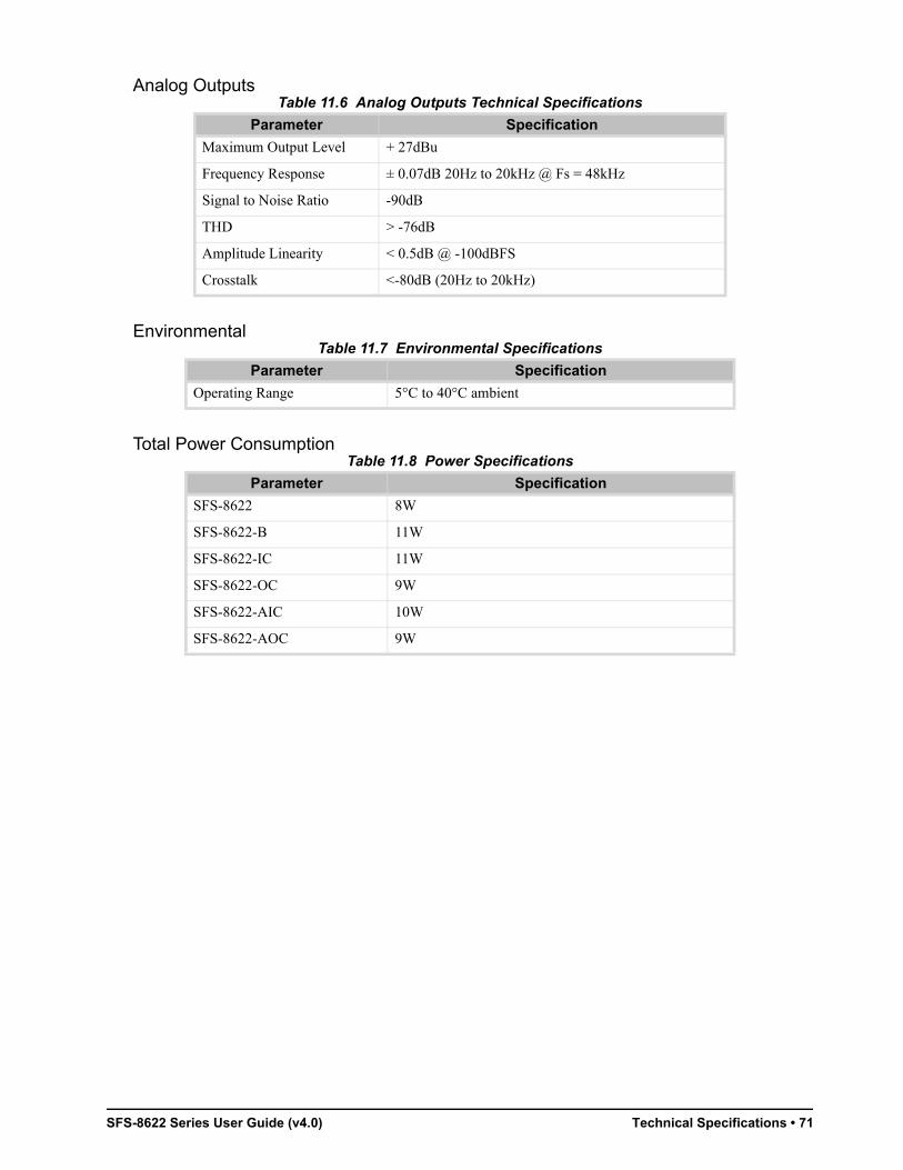
SFS-8622 Series User Guide (v4.0) Technical Specifications • 71
Analog Outputs
Environmental
Total Power Consumption
Table 11.6 Analog Outputs Technical Specifications
Parameter Specification
Maximum Output Level + 27dBu
Frequency Response ± 0.07dB 20Hz to 20kHz @ Fs = 48kHz
Signal to Noise Ratio -90dB
THD > -76dB
Amplitude Linearity < 0.5dB @ -100dBFS
Crosstalk <-80dB (20Hz to 20kHz)
Table 11.7 Environmental Specifications
Parameter Specification
Operating Range 5°C to 40°C ambient
Table 11.8 Power Specifications
Parameter Specification
SFS-8622 8W
SFS-8622-B 11W
SFS-8622-IC 11W
SFS-8622-OC 9W
SFS-8622-AIC 10W
SFS-8622-AOC 9W

72 • Technical Specifications SFS-8622 Series User Guide (v4.0)

SFS-8622 Series User Guide (v4.0) Channel Status Data • 73
Channel Status DataThis chapter provides additional information for channel status bits.
Channel Status Data Table
Table 12.1 shows the channel status bit information that is used for all output audio.
Passing the Status Bytes
The card replaces Channel Status Bytes according to Table 12.1 or passes Status Bytes through from input to output. The following conditions must be met for Status Bytes to pass:
• AES inputs must be 48kHz synchronous
• SRC is set to OFF
• Data Word Length in the Channel Status Bytes must match what is embedded
Table 12.1 Channel Status Data
Byte Bit Function Transmitted0 0 Professional or Consumer use of Channel Status Block Professional (1)
1 Normal Audio or Non-Audio Mode Normal Audio (0)
2-4 Emphasis No Emphasis (100)
5 Lock Indication Locked (0)
6-7 Sampling Rate 48kHz (01)
1 0-3 Channel Mode 2 channel stereo (0001)
4-7 User Bit Mode 192-bit (0001)
2 0-2 Auxiliary Bit Usage 20-bit audio sample, Aux bits undefined (000)
3-5 Sample Word Length 20- or 24-bits (101)
6-7 Alignment Level Not Indicated (00)
3 0-7 Multi-channel Modes Undefined (0)
4 0-1 Digital Audio Reference Signal Not a Reference (0)
2 Reserved 0
3-6 Sampling Frequency Not Indicated (0000)
7 Sampling Frequency Scaling Flag No Scaling (0)
5 0-7 Reserved Unused (0)
6-9 ASCII Source ID Unused (0)
10-13 ASCII Destination ID Unused (0)
14-17 Local Sample Address Unused (0)
18-21 Time of Day Unused (0)
22 0-7 C Data Reliability Only the first 5 Status Bytes are marked as Reliable
All other Status Bytes are marked as Unreliable
23 0-7 CRC Calculated CRC

74 • Channel Status Data SFS-8622 Series User Guide (v4.0)

SFS-8622 Series User Guide (v4.0) Service Information • 75
Service Information
Troubleshooting Checklist
Routine maintenance to this openGear product is not required. In the event of problems with your card, the following basic troubleshooting checklist may help identify the source of the problem. If the frame still does not appear to be working properly after checking all possible causes, please contact your openGear products distributor, or the Technical Support department at the numbers listed under the “Contact Us” section.
1. Visual Review — Performing a quick visual check may reveal many problems, such as connectors not properly seated or loose cables. Check the card, the frame, and any associated peripheral equipment for signs of trouble.
2. Power Check — Inspect the power indicator LED on the distribution frame front panel for the presence of power. If the power LED is not illuminated, verify that the power cable is connected to a power source and that power is available at the power main. Confirm that the power supplies are fully seated in their slots. If the power LED is still not illuminated, replace the power supply with one that is verified to work.
3. Input Signal Status — Verify that source equipment is operating correctly and that a valid signal is being supplied.
4. Output Signal Path — Verify that destination equipment is operating correctly and receiving a valid signal.
5. Unit Exchange — Exchanging a suspect unit with a unit that is known to be working correctly is an efficient method for localizing problems to individual units.
Bootload Button
In the unlikely event of a complete card failure, you may be instructed by a Ross Technical Support specialist to perform a complete software reload on the card.
To reload the software on the card
1. Eject the card from the frame.
2. Press and hold the Bootload button, while re-inserting the card into the frame.
3. Release the button.
• The OK/ERROR LED flashes green while the card is waiting for a new software load.
• If a new software load is not sent to the card within 60 seconds, the card will attempt to re-start with its last operational software load.
• Software loads can be sent to the card via the connection on the rear of the frame.
Warranty and Repair Policy
The SFS-8622 is warranted to be free of any defect with respect to performance, quality, reliability, and workmanship for a period of FIVE (5) years from the date of shipment from our factory. In the event that your card proves to be defective in any way during this warranty period, Ross Video Limited reserves the right to repair or replace this piece of equipment with a unit of equal or superior performance characteristics.
Should you find that this card has failed after your warranty period has expired, we will repair your defective product should suitable replacement components be available. You, the owner, will bear any labor and/or part costs incurred in the repair or refurbishment of said equipment beyond the FIVE (5) year warranty period.
In no event shall Ross Video Limited be liable for direct, indirect, special, incidental, or consequential damages (including loss of profits) incurred by the use of this product. Implied warranties are expressly limited to the duration of this warranty.
76 • Service Information SFS-8622 Series User Guide (v4.0)
This User Manual provides all pertinent information for the safe installation and operation of your openGear product. Ross Video policy dictates that all repairs to the card are to be conducted only by an authorized Ross Video Limited factory representative. Therefore, any unauthorized attempt to repair this product, by anyone other than an authorized Ross Video Limited factory representative, will automatically void the warranty. Please contact Ross Video Technical Support for more information.
In Case of Problems
Should any problem arise with your card, please contact the Ross Video Technical Support Department. (Contact information is supplied at the end of this publication.)
A Return Material Authorization number (RMA) will be issued to you, as well as specific shipping instructions, should you wish our factory to repair your card. If required, a temporary replacement frame will be made available at a nominal charge. Any shipping costs incurred will be the responsibility of you, the customer. All products shipped to you from Ross Video Limited will be shipped collect.
The Ross Video Technical Support Department will continue to provide advice on any product manufactured by Ross Video Limited, beyond the warranty period without charge, for the life of the equipment.
SFS-8622 Series User Guide (v4.0) Glossary • 77
GlossaryThe following terms are used throughout this guide:
Active image — the portion of the video picture area (production aperture) that is being utilized for output content. Active image excludes letterbox bars and pillarbox bars.
Card — openGear terminal devices within openGear frames, including all components and switches.
DashBoard — the DashBoard Control System.
DF — Differentiated Services.
DTVCC captions — CEA-708 captions.
Frame — the SFS-8622 frame that houses an SFS-8622 series card.
MIB — management information base.
Network Controller Card — the MFC-OG3-N and any available options unless otherwise noted.
NTSC captions — the CEA-608-D: Line 21 Data Services captions.
openGear frame — refers to the OGX-FR frame unless otherwise noted.
PAL — PAL-B and PAL-G unless otherwise stated.
PCR — program clock reference.
PID — packet identifier.
Production aperture — the image lattice that represents the maximum possible image extent in a given standard (e.g. the full size of all active pixels and active lines). For example, the 1080i production aperture would be 1920x1080.
Stream — a transport stream present at the port.
System— the mix of interconnected production and terminal equipment in your environment.
TCP — Transmission Control Protocol.
User — the person who uses an SFS-8622 series card.

78 • Glossary SFS-8622 Series User Guide (v4.0)