sfp store fusion platform - bacharach, inc
TRANSCRIPT

SFPSTORE FUSION PLATFORM
Quick Install Guide
Doc Ref. QSSFP Rev4 20th March 2020
Please also refer to the user manual for full installation details.
The content of this manual is the copyright of PARASENSE and must not be copied or reproduced without their written permission.
Important: All installation and maintenance work must be carried out by suitably qualified personnel only. All wiring
must be carried out in accordance with latest NEC, CEC or IEC requirements and current local regulations
Revision Details Checked
2-2: 20th Sept ‘16 Warning symbols added. SART wiring details updated AK
3-0: 24th Feb ‘17 Parasense Inc contact details updated. Stepwise branding removed AK
3-1: 9th Aug ‘17 SART installation notes modified. AK
3-2: 6th Apr ‘18 Branding updated. JB
Rev3 March 2020 Address change MC
Caution - risk of electric shock
Please read this guide before installing the equipment
Installation Guide
1. It must be mounted to a solid vertical surface or structure capable of supporting the stated weight. We recommend the surface be built from concrete blocks or brick. It must be positioned where the door can be fully opened and in a location that facilitates easy service and maintenance. The top of the enclosure should not be fitted higher than 1.8m (6ft) above floor level.2. Four fixing brackets are supplied loose with the monitor. They can be fitted vertically or horizontally. Choose the appropriate orientation, insert the bolt and nylon washer through the enclosure from the inside and tighten the bolts into the mounting brackets.3. Fixings should be 4mm (1/8”) or 5mm (3/16”) screws or bolts minimum 40mm (1.5”) long with plain washers and suitable wall plugs4. The enclosure is designed for cable entry from below. It has pre-drilled knock-outs for cabling. Ensure the mains cable uses the knock-out in the left end of the enclosure directly below the circuit breaker. If access is required from the side or above then the fitting must be of such a type to prevent ingress of moisture and dust. Failure to do so could invalidate the warranty.
SFP Quick Install Guide Rev4 March 2020
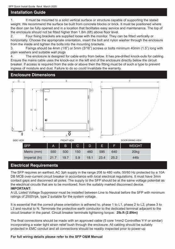
Enclosure Dimensions
Electrical Requirements
SFP A B C D E F WEIGHT
Metric (mm) 550 500 150 460 595 640 20kg
Imperial (In) 21.7 19.7 5.9 18.1 23.4 25.2 44lb
The SFP requires an earthed, AC 3ph supply in the range 208 to 480 volts, 50/60 Hz protected by a 10A DB MCB over-current circuit breaker in accordance with local electrical regulations. It must have 3mm contact gaps and disconnect all poles. The supply to the SFP should be at the same voltage potential as the electrical circuits that are to be monitored, from the suitably marked disconnect device. IMPORTANT:A UL Listed Voltage Suppressor must be installed between Line to Neutral before the SFP with minimum ratings of 2500Vpk, type 2 suitable for the system voltage.
It is essential that the correct phase orientation is adhered to, phase 1 to L1, phase 2 to L2, phase 3 to L3 and neutral to N. Terminate the protective earth conductor to the dedicated terminal adjacent to the circuit breaker in the panel. Circuit breaker terminals tightening torque: 2lb.ft (2.8Nm)
The final connections should be made with an approved cable (5 core 1mm2 Controlflex Y-Y or similar) incorporating a water tight strain relief bush through the enclosure. All cabling should be suitably protected in EMC conduit and all connections should be readily inspected prior to power-up
For full wiring details please refer to the SFP O&M Manual

SFP Quick Install Guide Rev4 March 2020
SART (Spilt Auto-Ranging Transformer) Details
Parasense SARTs are available for 300A, 600A,1200A, 2000A and 2500A circuits.Run a suitable cable (shown below) from the SFP to the panel where the SARTs are installed. Label both ends with cable identification tags. All wiring to be installed in EMT conduit as required by NEC, state and location requirements and Clients best practice specifications. All conduit connection to the Parasense equipment shall be water-tight and enter into the base of the monitor. Connections to the SART flying lead tails shall be made using UL approved twist-on wire connectors and in the enclosure that the SARTs are installed. The connections shall not be made inside conduit.The SART flying leads are red and black. Red should ultimately be connected to the terminal marked P on the PCB. Black should ultimately be connected to the terminal marked N on the PCBA label on the side of the SART shows the designation along with an arrow indicating the correct installation orientation. Use the A, B, and C phase notation on the label by circling the appropriate letter to match the phase that it is monitoring. Secure the SART to the power cable with a tie wrapFor full installation details please refer to the SFP O&M Manual and SART Install Guide
Internal Environmental Sensor. Locate the internal sensor approximately 2.5 to 3.0 metres above the floor. The sensor should not be mounted on an external wall or near a heat source.External Environmental Sensor: It is essential that the RSTHL external sensors are installed in a location that is 1. Shaded from the sun all day, preferably on a north-facing wall. 2. Well ventilated to avoid heat build up. 3. Away from potential heat sources such as condensers, ventilation ducts, AHUs etc. 4. Away from reflective surfaces. 5. At least 2 metres above the surface.
The connections should be made as per the below drawings using the cable stated. For RS485 network connection details and terminating resistor notes, please see the section titled ‘Cluster Point Networking’
Environmental Sensor Installation
SFP Quick Install Guide Rev4 March 2020
Relay Connections
Cluster Point Networking
Control Relays: 8 separate volt-free changeover relays are available on the SFP Network Module, rated at 6A AC or 5A DC (resistive). Contact voltages should not exceed 277V AC or 30V DC.
Fault / Alarm relay: a separate volt free changeover relay is available on the SFP Network Module, rated at 6A AC or 5A DC (resistive). Contact voltages should not exceed 277V AC or 30V DC.
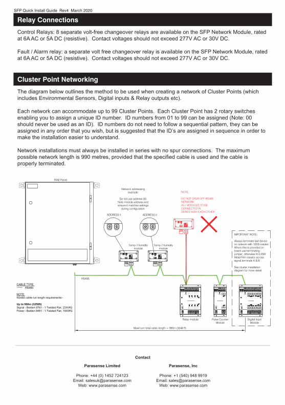
The diagram below outlines the method to be used when creating a network of Cluster Points (which includes Environmental Sensors, Digital inputs & Relay outputs etc).
Each network can accommodate up to 99 Cluster Points. Each Cluster Point has 2 rotary switches enabling you to assign a unique ID number. ID numbers from 01 to 99 can be assigned (Note: 00 should never be used as an ID). ID numbers do not need to follow a sequential pattern, they can be assigned in any order that you wish, but is suggested that the ID’s are assigned in sequence in order to make the installation easier to understand.
Network installations must always be installed in series with no spur connections. The maximum possible network length is 990 metres, provided that the specified cable is used and the cable is properly terminated.
Contact
Parasense Limited
Phone: +44 (0) 1452 724123Email: [email protected]
Web: www.parasense.com
Parasense, Inc
Phone: +1 (540) 948 9919Email: [email protected]
Web: www.parasense.com