sf6 in electrical power equipment - ecology and economy guide no. 276 definition in iec
TRANSCRIPT

SFSF66 in electrical power equipment in electrical power equipment --Ecology and EconomyEcology and Economy
Berlin, 1. July 2010

Page 2 July 1, 2010 Energy SectorSF6 in electric power equipment
© Siemens AG
Content
Introduction
Properties of SF6
Applications for the use of SF6 equipment
SF6 as a greenhouse gas – Emissions
SF6 as a greenhouse gas – History
SF6 as a greenhouse gas – Translation of Kyoto targets into EU law
Criteria for the use of SF6 equipment and application
Environmental friendly design and production of SF6 equipment
Overview of latest standards and publications
Market trends
Summary

Page 3 July 1, 2010 Energy SectorSF6 in electric power equipment
© Siemens AG
SF6 in application in power engineering since the middle of the 60ies First at high-voltage level >52kV:
High-voltage switchgear, circuit-breakers Since the beginning of the 80ies, also at medium-voltage level ≤52kV:
Primary distribution switchgear, secondary distribution switchgear (RMU)
New technical possibilities Compact design saves space and volume:
Conventional systems / SF6 technology Higher switching capacities:
Minimum-oil circuit-breakers, air-blast breakers / SF6 circuit-breakers (>110kV)
At the beginning of the 90ies, ecological awareness Contribution to greenhouse effect
Introduction

Page 4 July 1, 2010 Energy SectorSF6 in electric power equipment
© Siemens AG
IntroductionMore than 40 years of operational life-time experience
The equipment is gastight
Since more than 40 years in serviceBerlin, UW Wittenau, Vattenfall Europe, 123 kV, 31.5 kA
1968
State-of-the-art 145 kV, 40kA GIS
2009

Page 5 July 1, 2010 Energy SectorSF6 in electric power equipment
© Siemens AG
IntroductionMore than 27 years of operational life-time experience for MV switchgear
The equipment is gastight
Since more than 27 years in serviceUW Kulmbach Mitte, E.ON Bayern AG, 24 kV, 16 kA
1982
State-of-the-art 24 kV, 25 kA, Double Busbar, Type NXPLUS
2009

Page 6 July 1, 2010 Energy SectorSF6 in electric power equipment
© Siemens AG
SF6 is a colorless, odorless and chemically neutral (inert) gas
SF6 is 5 times heavier than air, non-toxic,and contains no dangerous components
SF6 is not a hazardous material
SF6 has no ecologically toxic potential
SF6 does not endanger the ozone layer
SF6 is a potent greenhouse gas
SF6 has excellent electrical properties
Properties of SF6
Page 7 July 1, 2010 Energy SectorSF6 in electric power equipment
© Siemens AG
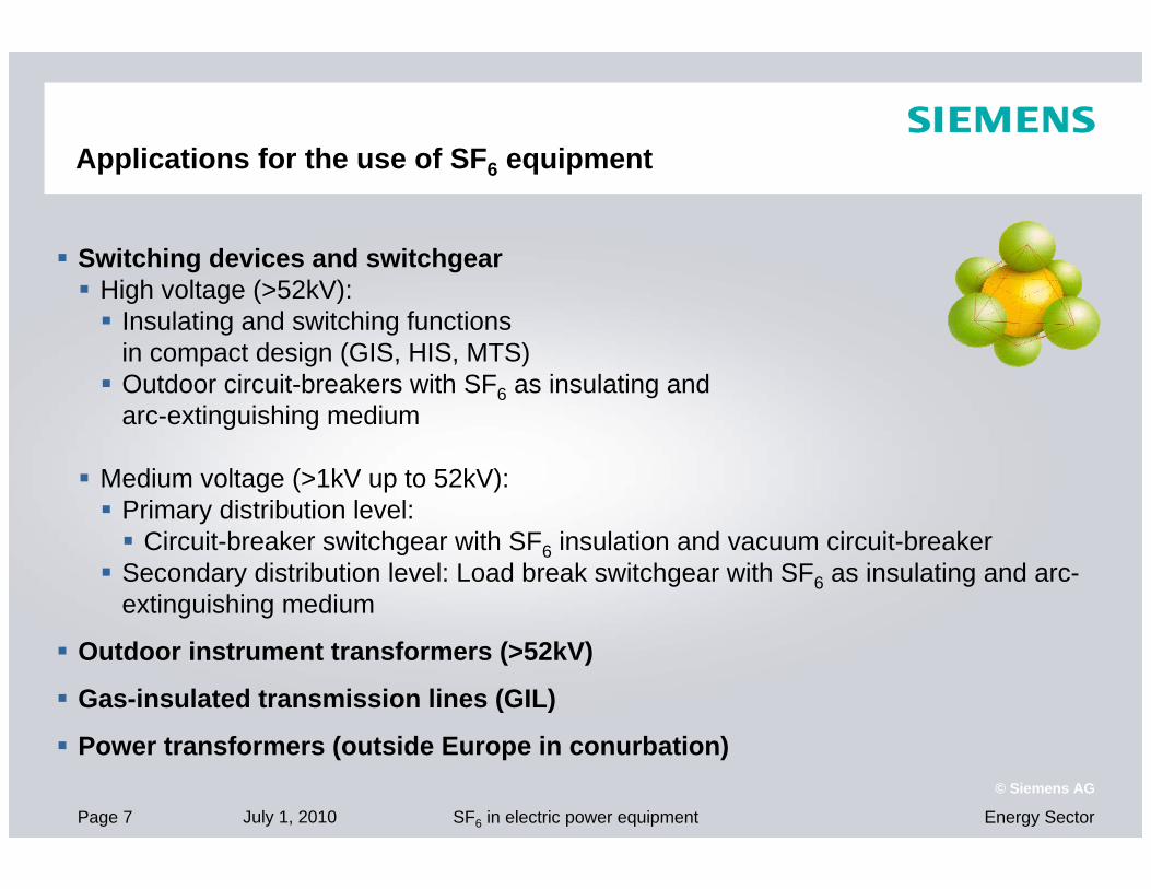
Applications for the use of SF6 equipment
Switching devices and switchgear High voltage (>52kV): Insulating and switching functions
in compact design (GIS, HIS, MTS) Outdoor circuit-breakers with SF6 as insulating and
arc-extinguishing medium
Medium voltage (>1kV up to 52kV): Primary distribution level: Circuit-breaker switchgear with SF6 insulation and vacuum circuit-breaker Secondary distribution level: Load break switchgear with SF6 as insulating and arc-
extinguishing medium
Outdoor instrument transformers (>52kV)
Gas-insulated transmission lines (GIL)
Power transformers (outside Europe in conurbation)

Page 8 July 1, 2010 Energy SectorSF6 in electric power equipment
© Siemens AG
SF6 as a greenhouse gas – Emissions
Technical recommendation in Cigré SF6-Handling Guide No. 276 Definition in IEC-standards
SF 6
Emission
SFSF66--handling losseshandling losses SFSF66--leakagesleakages
Emission EmissionEmission

Page 9 July 1, 2010 Energy SectorSF6 in electric power equipment
© Siemens AG
CarbonCarbon Dioxide CODioxide CO22
Helium HeNeon Ne
Methane CH4
[ppm]
18
380 (0,038%)
51,8
HydrogenHydrogen HH22
Nitrous Oxide N2O
Carbon Monoxide COOzon O3
[ppb
]
500(5 e-5%)
310
100
21% Oxygen O2
0,93% 0,93% ArgonArgon
ArAr
78% Nitrogen N2
other30
SF6 as a greenhouse gas – EmissionAtmospheric Composition
0,07% 0,07% TraceTrace GasGas
other
5 ppt

Page 10 July 1, 2010 Energy SectorSF6 in electric power equipment
© Siemens AG
Total SF6-emission contribution only 0,28%SF6-emission from electric power equipment: 0,05%Closed and sealed pressure systems in Germany: 0,03%
Other SF6-emission sources were: magnesium and aluminium industry, footwear, tyres,window noise insulation, military applications, semiconductor industry, medical devices (mainly „open applications“)
Situation of GHG in Europe before the regulationGreenhouse gas emission in the EU-15, 2002
8% N2O
2% HFC, PFC and SF6
8% CH4
82% CO2
14% SF6
18% PFC 78% HFC
Page 11 July 1, 2010 Energy SectorSF6 in electric power equipment
© Siemens AG
1) Coordinating Committee for the Associations of Manufacturers of Industrial Electrical Switchgear and Control gear in the European Union (now renamed/reorganized to “T&D Europe”)
2) European Union of the Electricity Industry (utilities/users)Ecofys-Study: https://www.zvei.org/fileadmin/user_upload/Fachverbaende/Energietechnik/Brancheninformationen/SF6_in_Schaltanlagen/Ecofys_SF6_Study_Final_Report_22Nov.pdf
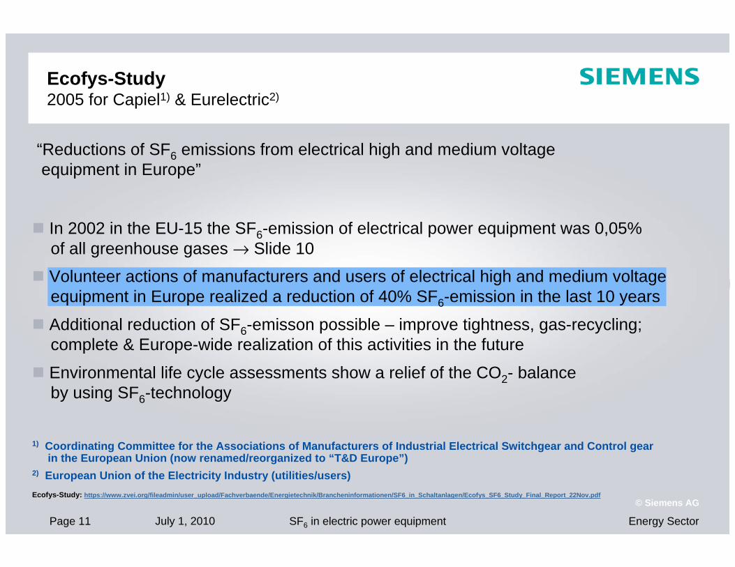
In 2002 in the EU-15 the SF6-emission of electrical power equipment was 0,05% of all greenhouse gases → Slide 10
Volunteer actions of manufacturers and users of electrical high and medium voltage equipment in Europe realized a reduction of 40% SF6-emission in the last 10 years
Additional reduction of SF6-emisson possible – improve tightness, gas-recycling; complete & Europe-wide realization of this activities in the future
Environmental life cycle assessments show a relief of the CO2- balance by using SF6-technology
“Reductions of SF6 emissions from electrical high and medium voltage equipment in Europe”
Ecofys-Study 2005 for Capiel1) & Eurelectric2)

Page 12 July 1, 2010 Energy SectorSF6 in electric power equipment
© Siemens AG
1988 The Intergovernmental Panel on Climate Change (IPCC) was founded by the United Nations Environment Program (UNEP) and the World Meteorological Organization (WMO).
Main task:Evaluation of the risks of climatic change and compilation of preventivestrategies by means of expertise reports.
1997 First “Voluntary Commitment” of the German manufacturers and operators concerning reduction of SF6-emissions in switchgear.
1997 Definition of greenhouse gases with a high Global Warming Potential (GWP) at the climate conference in Kyoto (Japan)Gas types: Carbon dioxide (CO2), methane (CH4), dinitrogen monoxide (laughing gas,N2O), hydrochlorofluorocarbons(H-FKW / HFCs), perfluorohydrocarbons (FKW / PFC) and sulfur hexafluoride (SF6)
SF6 as a Greenhouse Gas History – IPCC and the Climate Conference at Kyoto (1988-1997)

Page 13 July 1, 2010 Energy SectorSF6 in electric power equipment
© Siemens AG
Kyoto target, worldwide (issue 1997): Reduction of greenhouse gas emissions by 5.2% in the period 2008-2012 based emission level of 1990
Kyoto target, Europe (issue 1997):Reduction of greenhouse gas emissions in the EU by 8% in the period 2008-2012* (in Germany 21%) based on the emissionlevel of 1990.
Within the EU, the member states have agreed on different targets for the reduction or increase of emissions from greenhouse gases.
SF6 as a Greenhouse Gas History – Kyoto Targets (1997)
Reduction
Increase
Emissions from greenhouse gases in [%]
Luxembourg
Denmark
Germany
Austria
United Kingdom
Belgium
Italy
Netherlands
Finland
France
Sweden
Ireland
Spain
Greece
Portugal
EU -8
*) Follow-up agreement to be signed in 12/2009 in Copenhagen
Page 14 July 1, 2010 Energy SectorSF6 in electric power equipment
© Siemens AG
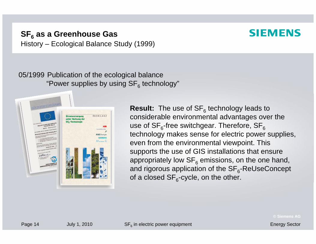
05/1999 Publication of the ecological balance “Power supplies by using SF6 technology”
SF6 as a Greenhouse GasHistory – Ecological Balance Study (1999)
Result: The use of SF6 technology leads to considerable environmental advantages over the use of SF6-free switchgear. Therefore, SF6technology makes sense for electric power supplies, even from the environmental viewpoint. This supports the use of GIS installations that ensure appropriately low SF6 emissions, on the one hand, and rigorous application of the SF6-ReUseConcept of a closed SF6-cycle, on the other.

Page 15 July 1, 2010 Energy SectorSF6 in electric power equipment
© Siemens AG
01/2004 Publication of the ecological balance in medium voltage (ordered by ZVEI, VDE FNN, Solvay, supported by BMU / UBA, TÜV, RWTH Aachen)
Result Transmission losses (I2R losses) causes the main part to the greenhouse effect. Every switchgear – regardless of the insulating medium – contribute to the greenhouse effect to a low extent. The only difference is the contribution of the respective drivers to the total emission.
SF6 as a Greenhouse GasHistory – Ecological Balance Study (2004)
5% by material
Air-insulatedswitchgear (AIS)
SF6-insulatedswitchgear (GIS)
90% by transmission losses
10% by material80% by transmission losses
15% by SF6 emissions
5% by material
Page 16 July 1, 2010 Energy SectorSF6 in electric power equipment
© Siemens AG
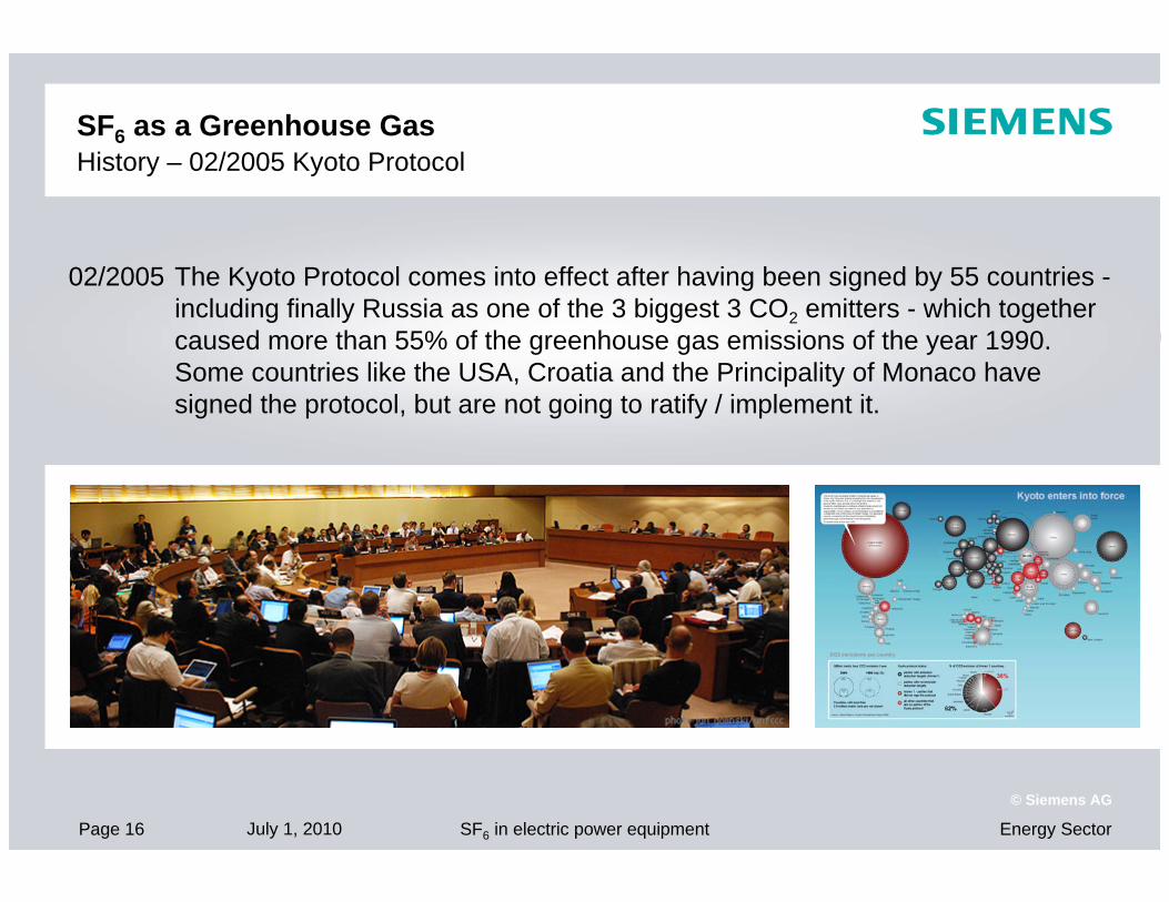
02/2005 The Kyoto Protocol comes into effect after having been signed by 55 countries -including finally Russia as one of the 3 biggest 3 CO2 emitters - which together caused more than 55% of the greenhouse gas emissions of the year 1990.Some countries like the USA, Croatia and the Principality of Monaco have signed the protocol, but are not going to ratify / implement it.
SF6 as a Greenhouse GasHistory – 02/2005 Kyoto Protocol
Seite 17Copyright Siemens AG
Energy Sector - Power Transmission High Voltage SubstationsPeter Glaubitz
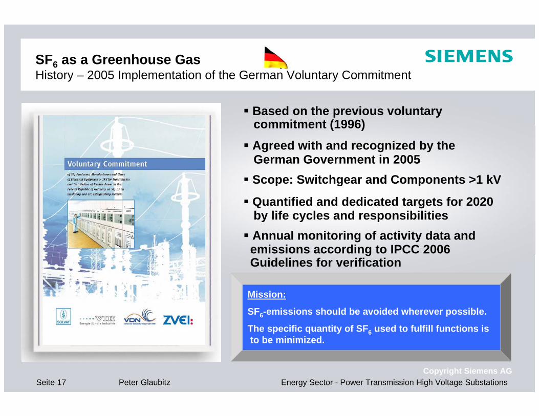
SF6 as a Greenhouse GasHistory – 2005 Implementation of the German Voluntary Commitment
Based on the previous voluntary commitment (1996)
Agreed with and recognized by the German Government in 2005 Scope: Switchgear and Components >1 kV
Quantified and dedicated targets for 2020 by life cycles and responsibilities Annual monitoring of activity data and emissions according to IPCC 2006 Guidelines for verification
Mission:
SF6-emissions should be avoided wherever possible.
The specific quantity of SF6 used to fulfill functions is to be minimized.

Seite 18Copyright Siemens AG
Energy Sector - Power Transmission High Voltage SubstationsPeter Glaubitz
SF6 as a Greenhouse GasHistory – 2005 German Voluntary Commitment (Examples for Participants)
Voluntary Agreement ParticipationSF6 ProducerOperator High VoltageManufacturer of Power EquipmentOperator Medium Voltage
100% 100% 98% 90%

Page 19 July 1, 2010 Energy SectorSF6 in electric power equipment
© Siemens AG
SF6 is considered in some articles only
The use of SF6 in electric power equipment is permitted
Certain measures to be carried out by manufacturers and users have been implemented
Amendments have been released to describe measures more in detail
EU-F-Gas regulation 842/2006EU 27+3
„Regulation (EC) No 842/2006 of the European Parliament and of the Council on fluorinated greenhouse gases“

Page 20 July 1, 2010 Energy SectorSF6 in electric power equipment
© Siemens AG
(EC) 1493/2007 definitions, format of reporting
Article 4 „Recovery“
(EC) 1494/2007 definitions, form of labels
(EC) 305/2008 definitions, minimumrequirement on certification of staff
European F-Gas-regulation 842/2006Relevant articles for SF6 electric power equipment
Recovery by certified staff only
Article 7 „Labelling“
Article 5 „Training and certification“
Regulation (EC)Nr. 842/2006
on certain fluorinated
greenhouse gases*
*) “certain fluorinated greenhouse gases” means hydrofluorocarbons (HFCs), perfluorocarbons (PFCs) and sulphur hexafluoride (SF6)
Article 6 „Reporting“

Page 21 July 1, 2010 Energy SectorSF6 in electric power equipment
© Siemens AG
European F-Gas-regulation 842/2006, article 4 „Recovery”Optimized gas recovery needs „State-of-the-Art“ equipment
1mbar SF6-maintenance unit
SF6– measurement device
%- SF6, dew-point,temperature,
SF6-byproducts
SF6– collecting device
for measurement of gas
Source: DILO
SF6– collecting device
Evacuation of SF6without losses from a MV RMU
Example for typical HV equipment MV equipment

Page 22 July 1, 2010 Energy SectorSF6 in electric power equipment
© Siemens AG
With State-of-the-art handling equipment SF6 recovery of each gas compartment till very low pressure (1-20 mbar) is possible, thus securing losses of at least less than 2% during maintenance and end of life.
0
1
2
3
4
5
6
7
8
9
10
0 20 40 60 80 100 120 140 160 180 200
SF6 residual pressure [mbar]
SF6
resi
dual
qua
ntity
[kg]
SFSF66--residual quantity (emission) dependence on the SFresidual quantity (emission) dependence on the SF66 rated filling pressure / rated filling pressure / compartment size / SFcompartment size / SF6 6 residual pressureresidual pressure
source: Cigré-Guide no. 276, application of table 25; Example: GIS Siemens
European F-Gas-regulation 842/2006, article 4 „Recovery”Optimized SF6 handling
420 kV-circuit breaker, 3-pole- volume: approx. 7000 l
- working pressure: 6,6 bar abs.
- SF6-amount: approx. 300 kg
- SF6-density: 43 g/l420 kV-disconnector, 3-pole- volume: approx. 870 l
- working pressure: 4,8 bar abs.
- SF6-amount: approx. 27 kg
- SF6-density: 26,7 g/l
SF6
SF6

Page 23 July 1, 2010 Energy SectorSF6 in electric power equipment
© Siemens AG
„Commission regulation No. 305/2008 establishing minimum requirements and the conditions for mutual recognition for the certification of personnel recovering certain fluorinated GHG from HV switchgear“
Process and responsibilities
Individual Individual certificatecertificate
Training(not subject to conditions of regulation)
Evaluation body/
Examination(content defined)
Proof of competence
Certification body issues certifications
Evaluation body and Certification body have
to be independent
*) regulation refers to HV switchgear only
European F-Gas-regulation 842/2006, article 5 „Training and certification“ together with regulation 305/2008*
Page 24 July 1, 2010 Energy SectorSF6 in electric power equipment
© Siemens AG
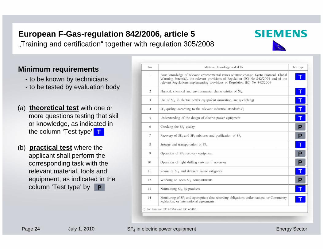
(a) theoretical test with one or more questions testing that skill or knowledge, as indicated in the column ‘Test type’ by
(b) practical test where the applicant shall perform the corresponding task with the relevant material, tools and equipment, as indicated in the column ‘Test type’ by
Minimum requirements - to be known by technicians- to be tested by evaluation body
T
TTTT
T
T
T
T
PP
PP
P
T
P
European F-Gas-regulation 842/2006, article 5 „Training and certification“ together with regulation 305/2008

Page 25 July 1, 2010 Energy SectorSF6 in electric power equipment
© Siemens AG
European F-Gas-regulation 842/2006, article 6 „Reporting“ together with regulation 1493/2007
Reporting of producers, importers and exporters in the EU
Submission of the report by 31 March of the year following the year for which the report applies
Report shall be submitted to the EU commission and the competent authority of the member state
For utilities usually not relevant
„Commission regulation No 1493/2007 establishing the format for the report to be submitted by producers, importers and exporters of certain fluorinated GHG“
sWill be done by the
manufacturer
sWill be done by the
manufacturer
sWill be done by the
manufacturer
Page 26 July 1, 2010 Energy SectorSF6 in electric power equipment
© Siemens AG
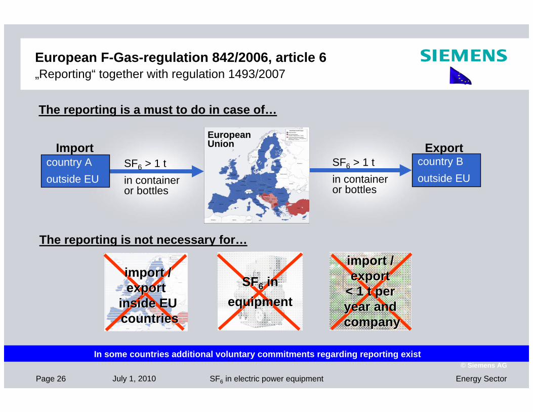
SF6 > 1 tin container or bottles
SF6 > 1 t in container or bottles
country Aoutside EU
country Boutside EU
Import ExportEuropean Union
The reporting is not necessary for…
European F-Gas-regulation 842/2006, article 6 „Reporting“ together with regulation 1493/2007
The reporting is a must to do in case of…
import / import / export export
inside EU inside EU countriescountries
SFSF66 ininequipmentequipment
import / import / export export
< 1 t per < 1 t per year and year and companycompany
In some countries additional voluntary commitments regarding reporting exist

Page 27 July 1, 2010 Energy SectorSF6 in electric power equipment
© Siemens AG
„Commission regulation establishing the form of labels and additional labelling requirements as regards products and equipment containing certain fluorinated GHG“
It applied from 1. April 2008
SF6 labelling on the product itself
Information in the instruction manual
European F-Gas-regulation 842/2006, article 7 „Labelling“ together with regulation 1494/2007
sWill be done by the
manufacturer
sWill be done by the
manufacturer

Page 28 July 1, 2010 Energy SectorSF6 in electric power equipment
© Siemens AG
additional label* NEW
Standards required SF6-weight already in the past: declaration of „weight of gas” according to IEEE C37.122 or IEC 62271-203
European F-Gas-regulation 842/2006, article 7 „Labelling“ together with regulation 1494/2007
Weight of SF6 – filling 99 kg
*) Content defined in the regulation but the form can vary between the different manufactures
The label shall be placed clearly, indelibly and adjacent to the service point of the equipment

Page 29 July 1, 2010 Energy SectorSF6 in electric power equipment
© Siemens AG
Labelling of productsThe instruction manual must contain a note in the sense of…
“This equipment contains the fluorinated greenhouse gas SF6 covered by the Kyoto Protocol and with a global warming potential (GWP) 22 800. SF6 shall be recovered and not released into the atmosphere. For further information on use and handling of SF6 please refer to IEC 62271-303: High-voltage switchgear and control gear – Part 303 Use and handling of sulphur hexafluoride (SF6)”
Instruction Manual
European F-Gas-regulation 842/2006, article 7 „Labelling“ together with regulation 1494/2007
Source: T&D Europe, Guide for Manufacturers of HV Switchgear containing SF6…
22800

Page 30 July 1, 2010 Energy SectorSF6 in electric power equipment
© Siemens AG
European F-Gas-regulation 842/2006 Article 10: Review
„Paragraph 2“
By July 4, 2011, the Commission shall publish a report based on theexperience of the application on the regulation
► the Consulting company „Oekorecherche“ got in 12/2009 the order from theEU-Commission to prepare this review report
► Support regarding SF6 in electric power equipment is given to Oekorecherche by various organisations in our sector
► A preliminary report is scheduled for autumn 2010
Current status

Page 31 July 1, 2010 Energy SectorSF6 in electric power equipment
© Siemens AG
Criteria for the Use of SF6 Equipment (1)High Dielectric Strength
High insulating and breaking capacity At the same atmospheric pressure
( 100 kPa = 1.0 bar ) Dielectric strength approx. 3 times
higher than that of air insulation
At double atmospheric pressure( 200 kPa = 2.0 bar ) Dielectric strength approx. 6 times
higher than that of air insulation
Filling pressure in medium-voltage switchgear: 50 kPa to 120 kPa Depending on voltage level and
requested dielectric strength
Dis
rupt
ive
disc
harg
e vo
ltage
[kV
]
Electrode distance [mm]
0
50
100
150
200
250
0 10 20 30 40
SF6, 5.0 bar
SF6, 2,5 bar
SF6, 2,0 bar
SF6, 1,5 bar
SF6, 1,0 bar
Air, 1,0 bar
*

Page 32 July 1, 2010 Energy SectorSF6 in electric power equipment
© Siemens AG
Criteria for the Use of SF6 Equipment (2)Reduced Dimensions
Compact design Flexible selection of location close to load centers Utilization of existing buildings with more switchgear panels
Gas-insulatedAir/solid-insulated Cast-resin insulated
2.2 m35.8 m38.7 m314.5 m319 m3Panel8 m324 m329 m347 m383 m3Building
since 1982since 1980since 1970until 1970until 1950Year
Air-insulated
Erected on site Workshop
manufactureFactory-
assembled,type-tested
Factory-assembled,
compact
Factory-assembled,
SF6-insulated

Page 33 July 1, 2010 Energy SectorSF6 in electric power equipment
© Siemens AG
Criteria for the Use of SF6 Equipment (3)High Personal Safety
High personal protection Approximation to high voltage by mistake is excluded
by the design
IAC A FLR 40kA 1sIAC Internal arc classification
A Access for authorized persons
FLR Access from front, lateral, rear
40kA Short-circuit breaking current
1s Internal arc duration
We Are Ready !

Page 34 July 1, 2010 Energy SectorSF6 in electric power equipment
© Siemens AG
Criteria for the Use of SF6 Equipment (4)Climate, Service Life, Cost-Efficiency, Availability
Independence from ambient conditions Hermetic enclosure of the primary conductors
Sustained utilization of equipment Preservation of resources – reduced use of material Longer service life
High availability and reliability of supply Aging and impairment by pollution
and other external influences excluded by design
Low fire load Reduced use of plastic material
Reduced power losses at system and switchgear level Shorter primary circuits

Page 35 July 1, 2010 Energy SectorSF6 in electric power equipment
© Siemens AG
GIS today and in the futureEcological and economic advantages of GIS (case study)
Transmission LossesMaterial
SF6 Losses
GWP: Global Warming Potential
AIS GIS
52 TJ/a
38 TJ/a
AIS GISAIS GIS
- 27%
- 98%
- 21%2.750 tCO2 2.170tCO2
required floor space
8000 sqm
Less amount of material Lower energy losses
Compact design HV close by city
Ecological Economical
primary energy GWP*

Page 36 July 1, 2010 Energy SectorSF6 in electric power equipment
© Siemens AG
Reduced switchgear sizes in HV GIS
The developments within the last decades have led to smaller gas compartments of the switchgear and thus to considerably less used amount of SF6 at the same performance data.
[%]
0
10
20
30
40
50
60
70
80
90
100
68 70 72 74 76 78 80 82 84 86 88 90 92 94 96 98year
Size of building
Space requirement
Packing volume
8D2
8D68D8 8DN9
8DN8
example: the development of the Siemens GIS 145 kV
source: Siemens
06

Page 37 July 1, 2010 Energy SectorSF6 in electric power equipment
© Siemens AG
A significant reduction of SF6 was reached by using modern development tools, new materials and optimized production processes since the introduction of the GIS-technology in 1968.
Siemens GISSiemens GIS
Basis: cable bay with Basis: cable bay with double double busbarbusbarsystem including 2 system including 2 BB DS, 1 L DS, 1 CB, BB DS, 1 L DS, 1 CB, 3 ES3 ES
8D.5 8DQ1
420 kV8D.6 8DN8
145 kV8D.4 8DN9
245 kV
Amount of SFAmount of SF66
type of GIS
268 kg268 kg
85 kg
-- 68%68%
630 kg630 kg
143 kg
-- 77%77%
1361 kg1361 kg
450 kg450 kg
-- 67%67%
Significant reduced amount of SF6 in the equipment

Page 38 July 1, 2010 Energy SectorSF6 in electric power equipment
© Siemens AG
Equipment design – materialSF6-Tightness of aluminium vessels for HV switchgear
Machining PaintingCasting Design
state-of-the-art software
Beside requirements on SF6-tightness, pressure vessel regulations apply as well
Best quality Decade-long tightness
State-of-the-art production Process optimization Reliable partner
Ecological Economical
Page 39 July 1, 2010 Energy SectorSF6 in electric power equipment
© Siemens AG
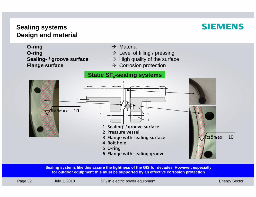
O-ring MaterialO-ring Level of filling / pressingSealing- / groove surface High quality of the surfaceFlange surface Corrosion protection
Sealing systems like this assure the tightness of the GIS for decades. However, especially for outdoor equipment this must be supported by an effective corrosion protection
1 Sealing- / groove surface 2 Pressure vessel3 Flange with sealing surface4 Bolt hole 5 O-ring6 Flange with sealing groove
Static SF6-sealing systems
Sealing systems Design and material

Page 40 July 1, 2010 Energy SectorSF6 in electric power equipment
© Siemens AG
1 Bearing 2 Bearing 3 Radial sealing packages
Radial sealing packages are an import factor for SF6-tightness of the GIS
1
23
Dynamic SF6-sealing systems
Sealing systems Design and material

Page 41 July 1, 2010 Energy SectorSF6 in electric power equipment
© Siemens AG
Component design development Cast-Resin partitions
Beside „external“ SF6-tightness „internal“ SF6-tightness (between 2
gas compartments) has to be assured as well
Production and testing in the factory (including gas permissible partitions
and other insulating parts)
Page 42 July 1, 2010 Energy SectorSF6 in electric power equipment
© Siemens AG
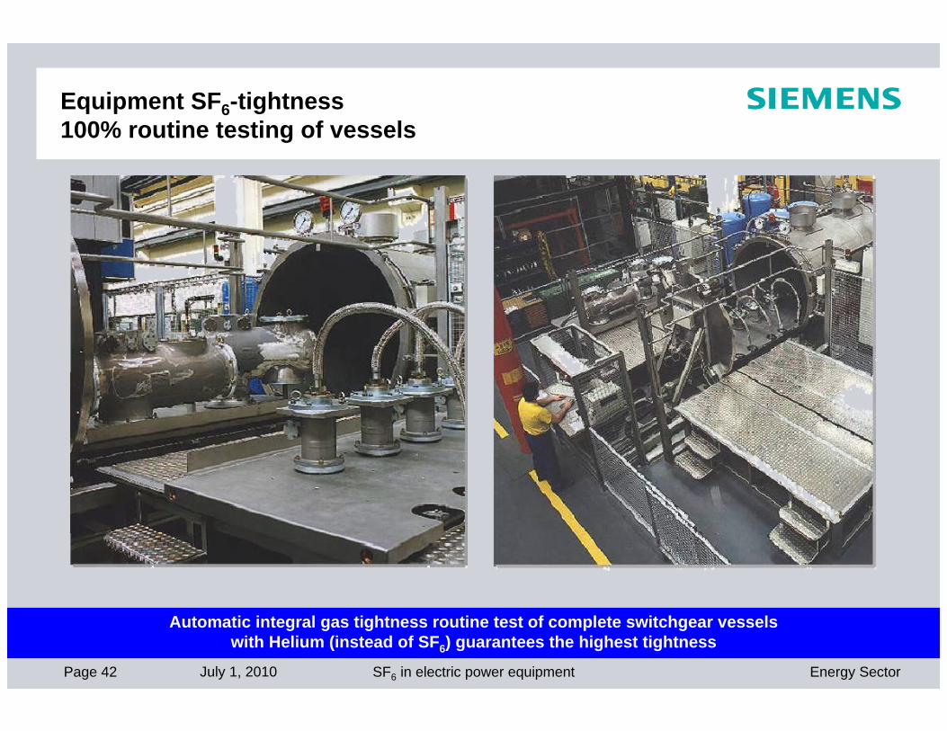
Automatic integral gas tightness routine test of complete switchgear vesselswith Helium (instead of SF6) guarantees the highest tightness
Equipment SF6-tightness 100% routine testing of vessels
Page 43 July 1, 2010 Energy SectorSF6 in electric power equipment
© Siemens AG
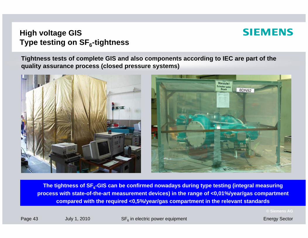
8DN92
Tightness tests of complete GIS and also components according to IEC are part of the quality assurance process (closed pressure systems)
The tightness of SF6-GIS can be confirmed nowadays during type testing (integral measuring process with state-of-the-art measurement devices) in the range of <0,01%/year/gas compartment
compared with the required <0,5%/year/gas compartment in the relevant standards
High voltage GIS Type testing on SF6-tightness
Page 44 July 1, 2010 Energy SectorSF6 in electric power equipment
© Siemens AG
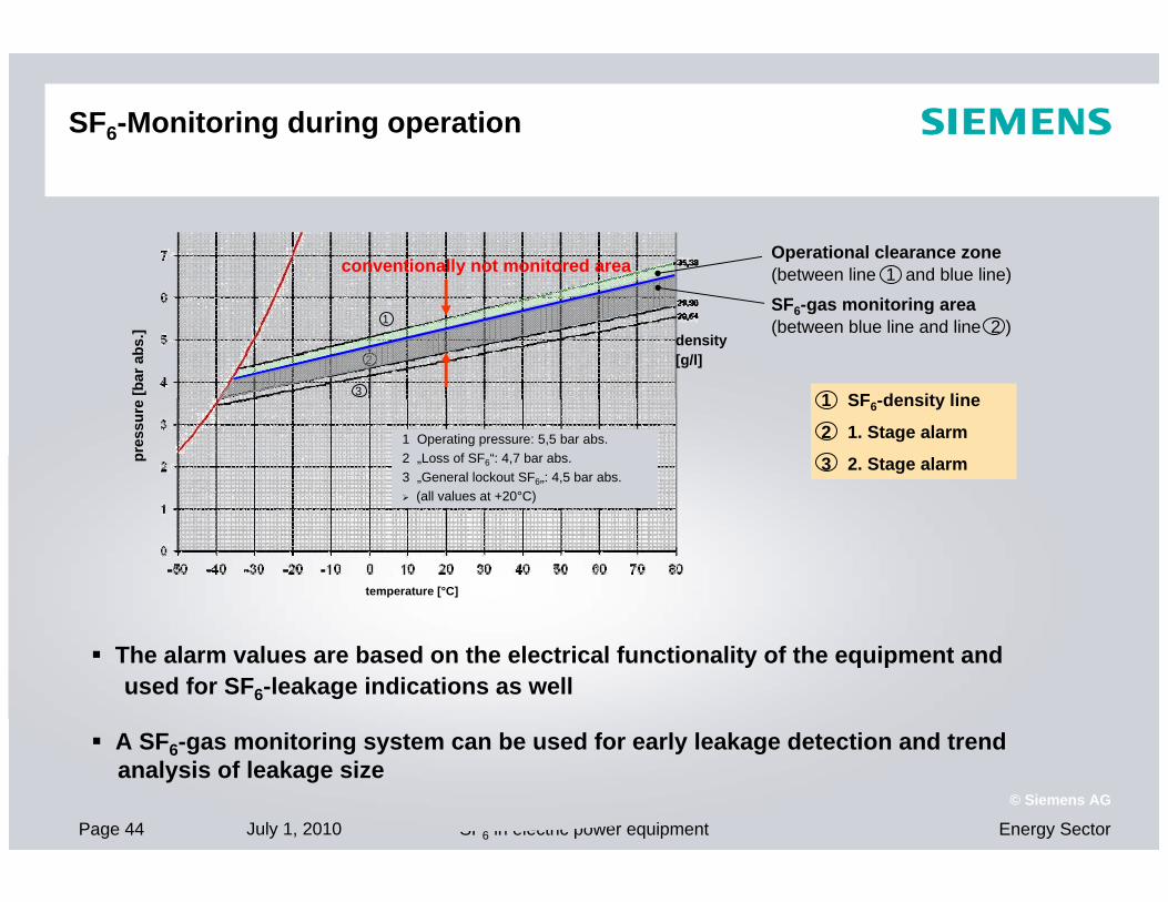
SF6-Monitoring during operation
The alarm values are based on the electrical functionality of the equipment andused for SF6-leakage indications as well
A SF6-gas monitoring system can be used for early leakage detection and trend analysis of leakage size
conventionally not monitored area
density [g/l]
pres
sure
[bar
abs
.]
temperature [°C]
1 Operating pressure: 5,5 bar abs.2 „Loss of SF6“: 4,7 bar abs.3 „General lockout SF6„: 4,5 bar abs. (all values at +20°C)
1
2
3
SF6-gas monitoring area(between blue line and line 2 )
1 SF6-density line
2 1. Stage alarm
3 2. Stage alarm
Operational clearance zone (between line 1 and blue line)

Page 45 July 1, 2010 Energy SectorSF6 in electric power equipment
© Siemens AG
SF6- Detection in GIS-BuildingsGeneral Aspects - Experience
- GIS are gastight for decades - as proved in the field
- GIS-gas compartments are equipped with SF6-densitiy monitors forfunctionality reasons (SF6-alarm in case of „small“ leakages)
- SF6-Detection equipment therefore very seldom required by customers
- Air condition not common in GIS-buildings
- Possible SF6-gas will accumulate on the ground (6x heavier than air)
- SF6-Detection equipment not recommended in papers or standards
- No incident known regarding leaking SF6-gas
However, SF6-detector for GIS-buildings are available

Page 46 July 1, 2010 Energy SectorSF6 in electric power equipment
© Siemens AG
SF6- Detection and Signalling in GIS-BuildingsEquipment
Source: DILO
Detection
Evaluation
Signalling
Page 47 July 1, 2010 Energy SectorSF6 in electric power equipment
© Siemens AG
SF6- Detection in GIS-BuildingsPossibilities
►12 Detectors (SF6 Network Monitors) can be connected to 1 Controller
► Principle: permanent supervision of ambient air for SF6
► Output of Controller can be used for various functions: signalling lamp, remote control, release for door opener, operating of ventilation system,….
► Ventilation system can be combined with air condition system (e.g. air circulation)
► Extraction by suction of gas-mixture at lowest point of the building another option
► Size of ventilation and extraction system are designed individually with regards to GIS
► Installation not necessary for functional reasons (leakages) but can be part of EHS-policy

Page 48 July 1, 2010 Energy SectorSF6 in electric power equipment
© Siemens AG
The reduction of SF6-emission has been achieved by
• permanent investments in state-of-the-art equipment
• continuous staff training
• constant processoptimization
2001 2002 2003 2004 2005 2006 2007 2008(Source: Siemens GIS Factory Berlin)
*) Output means delivered GIS bays
Out
put
Emission
Substantial decreasing emissions during assembly
more decantof SF6 Gas
moreoutput*
Page 49 July 1, 2010 Energy SectorSF6 in electric power equipment
© Siemens AG
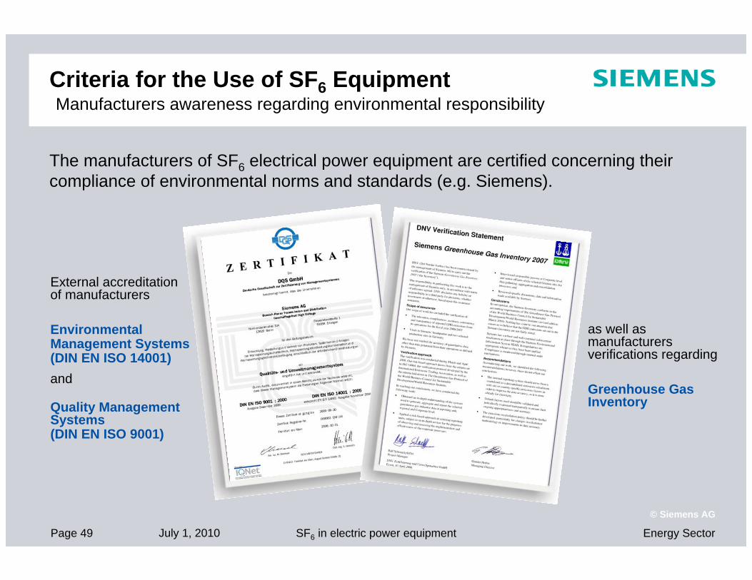
The manufacturers of SF6 electrical power equipment are certified concerning their compliance of environmental norms and standards (e.g. Siemens).
External accreditation of manufacturers
Environmental Management Systems (DIN EN ISO 14001)and
Quality Management Systems(DIN EN ISO 9001)
as well as manufacturers verifications regarding
Greenhouse Gas Inventory
Criteria for the Use of SF6 Equipment Manufacturers awareness regarding environmental responsibility

Page 50 July 1, 2010 Energy SectorSF6 in electric power equipment
© Siemens AG
Overview of the Latest Standards and Publications
IEC 62271-1 Common specifications for SF6-insulated and air-insulatedhigh-voltage switchgear and controlgear
IEC 62271-200 High-voltage switchgear and controlgear >1kV up to 52kV
IEC 62271-203 High-voltage switchgear and controlgear >52 kV
IEC 62271-303 Use and handling of SF6
IEC 60376 Specification for new SF6 gas
IEC 60480 Checking and treatment of sulfur hexafluoride (SF6) taken from electrical equipment
IEC: International Electrotechnical Commission for Standards

Page 51 July 1, 2010 Energy SectorSF6 in electric power equipment
© Siemens AG
Overview of the Latest Standards and PublicationsEU commission, Cigré and T&D Europe
Information for operators and technical personnel working with equipment containing fluorinated greenhouse gases
no. 234, Recycling of SF6
no. 276, Guide for Handling of SF6
no. xxx, SF6-Tightness Guide
SF6 in electrical equipment. Guide for operators and manufacturers
EU COMMISSION
CIGRÉ: International Council on large Electric SystemsT&D Europe: European Association of the Electricity Transmission and Distribution Equipment and Services Industry
Page 52 July 1, 2010 Energy SectorSF6 in electric power equipment
© Siemens AG
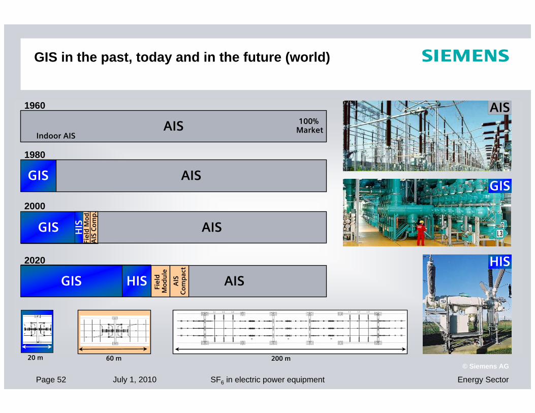
GIS in the past, today and in the future (world)
200 m20 m 60 m
AIS
1960
AIS
1980
GIS
2020
AISGIS HIS
Fiel
dM
od
ule
AIS
Co
mp
act
100% Market
Indoor AIS
2000
AISGIS HIS
Fiel
dM
od
.A
IS C
om
p.
HIS
GIS
HIS
AIS

Page 53 July 1, 2010 Energy SectorSF6 in electric power equipment
© Siemens AG
SF6 has excellent insulating and arc-extinguishing properties. Up to now, there are no alternatives in sight.
SF6 technology allows for electrical equipment with compact design, with a high personal safety, minimized fire load, preserving the resources and with a high availability and reliability of supply.
Due to their unique electrical properties, SF6 switchgear and equipment are indispensable for network operation in power transmission and distribution.
Ecological balances show: SF6 technology is ecologically responsible. Despite a high GWP, the CO2balance is better than for conventional designs due to lower transmission losses and reduced use of material.
Due to the high CO2 potential of SF6, emissions must be kept as low as possible. This is ensured by low leakage rates and handling losses during operation and at the end of the service life.
SummaryAdvantages for Ecology and Economy
Thank you very much Thank you very much for your attention!for your attention!
Berlin, July 1, 2010

Answers for energy.
Gas-insulated transmission lines (GIL)High-power transmission technology

Superior technology and excellent knowhow ensure quality and reliabilitySiemens GIL systems are based on the successful SF6 tubular conductor technol-ogy, which has been around for several decades. GIL consist of a central aluminum conductor with a typical electrical cross section of up to 5,300 mm2. The conductor rests on cast resin insulators, which center it within the outer enclosure. This enclo-sure is formed by a sturdy aluminum tube, which provides a solid mechanical and electrotechnical containment for the sys-tem. To meet up-to-date environmental and technical aspects, GIL are filled with an insulating gas mixture of mainly nitro-gen and a smaller percentage of SF6. For increased lifetime, the “performance line” product series has a longitudinal particle trap installed over the entire horizontal
route section. An automated orbital welding procedure, accompanied by tailored ultrasonic inspection tech-niques, ensures perfect gastightness of the aluminum tubes.
During service, the fully encapsulated design fully protects the GIL against environmental influences. Thanks to the technologically clear-cut, logical design and the use of high-quality materials, an absolutely maintenance-free product is achieved which requires external inspection only. And at the end of its service life, the issue of de-installation is solved. The GIL tubular system with all its components and the insulation gas mixture are 100 percent recyclable. These factors help to minimize lifetime costs.
Impressive practical record: GIL system in Germany’s Wehr power plantSiemens installed a GIL in a tunnel in the Wehr pumped-storage power station in the Black Forest as long ago as 1975. With a single-phase length of almost 4 km this installation is still a significant reference among worldwide GIL projects. Notwith-standing its service time, an inspection after 30 years showed that all components were still in top condition, and assured the customer that GIL will provide many more years of reliable operation.
5 5
6
43
2
2
1
160 m 4570 m
30 m
100 m
Wehr power plant, Germany
1 600 MVA transformer2 Encapsulated surge arresters3 Transfer switching units4 GIL connection5 Open-air surge arrester6 Overhead line
2
GIL flexibility: above- or belowground
Second-generation gas-insulated lines for high power transmission are the best option where environmental or structural considerations rule out the use of overhead transmission lines. The outstanding features of a GIL system are its high transmission capacity, superior electro-magnetic compatibility (EMC) to any other trans-mission system, low losses, high safety (no fire hazard) and flexible installation options. GIL can be laid aboveground, installed in tunnels or buried directly in the soil, depending on individual requirements.
GIL – high-power transmission technology

in case of an external impact. GIL systems are gastight and sealed for their lifetime. Consequently they retain their superior operating properties throughout their service life.
Excellent electromagnetic compatibility enables flexible route planningThe construction of the GIL results in much smaller electromagnetic fields – as much as 15 to 20 times smaller – than with conventional power transmission systems. This makes GIL suitable for com-pletely new routings through populated areas (e.g. next to hospitals or residential areas, in the vicinity of flight monitoring systems, etc.). GIL can be laid in combined infrastructure tunnels together with foreign elements (e.g. close to telecommunication equipment). Thus, GIL provides maximum flexibility for the planning of transmission networks in EMC-sensitive environments, where magnetic fields have to be avoided. Siemens GIL systems satisfy the most stringent magnetic flux density require-ments, for example, the Swiss limit of 1 μT.
Flexible grid connections – optimum grid integrationGIL systems consist of a manageable number of modular elements which can be combined according to defined techni-cal rules. Thus GIL systems are not limited in their entire length. Moreover, they are suited for almost any kind of routing, for instance through built-up areas or road crossings, on marshy ground, etc. To meet these requirements the actual installation of GIL makes use of sophisti-cated laying techniques. These techniques are based on the well-proven procedures of the pipeline construction industry, adding some product-specific modifica-tions. Consequently project implementa-tion time can be kept to a minimum.
Due to their outstanding design features Siemens GIL are remarkably flexible for different applications. Thanks to their transmission capacity and low losses GIL can be linked directly, one-to-one to over-head lines, continuing the lines under-ground. As a result of the low electrical
capacitance of GIL, compensating reactors are generally not required, even for very long GIL sections of up to 70 km. The technical particulars of Siemens GIL allow for an autoreclosure pattern for the OHL, so that no modification of the protection concept is needed. For the same reasons, GIL are also perfectly suitable for direct connection to substations or transformers.
Outstanding safety in operationGIL systems by Siemens live up to their reputation not just with their technical specifications, but also by providing excellent operational safety. GIL systems are immune to hazards that are inherent to other power transmission systems. They are safe to touch in operation, as their housing is solidly grounded. They are fireproof and explosion-proof. The electrical insulation system is not subject to aging phenomena, which reduces the risk of internal failures to virtually zero. Siemens GIL are constructed employing separate gastight compartments of vari-able length, which further increases safety
3
Magnetic fields in microtesla (µT) for GIL, overhead transmission line and cable (XLPE, cross-bonding) for a 400 kV double system at 2 x 1,000 MVA load, GIL and cable laid at a depth of 1 m.
GIL
Cable
Overheadline
30
25
20
15
10
5
0
Mag
net
ic f
lux
de
nsi
ty B
[µ
T]
High EM compatibility
A comparison of the magnetic fields for different high-voltage transmission systems.

Aboveground installationGIL installation aboveground is a trouble-free option, even for extreme environ-mental conditions. GIL are unaffected by high ambient temperatures, intensive solar radiation or severe atmospheric pollution (such as dust, sand or moisture). Corrosion protection is not always neces-sary. Particularly high transmission power can be achieved with aboveground instal-lation.
Tunnel installationTunnels made up of prefabricated struc-tural elements are another quick and easy method of GIL installation. The tunnel elements are assembled in a trench, which is then backfilled to prevent any long-term disfiguring of the local land-scape. The GIL is installed once the tunnel has been completed. With this method of installation the land above the tunnel can be fully restored to agricultural use. Only a negligible amount of heat is dissi-pated to the soil from the GIL. The system stays accessible for easy inspection and high transmission capacity is ensured.
Vertical installationGas-insulated tubular conductors can be installed without a problem at any gradient, even vertically. This makes them a top solution especially for cavern hydropower plants, where large amounts of energy have to be transmitted from the underground machine transformer to the switchgear and overhead line on the surface. As GIL systems pose no fire risk, they can be installed in a tunnel or shaft that is accessible and can also be used for ventilation at the same time.
4
Versatility in application and laying methods
Flexibility for your success
Due to their unique properties GIL systems have become well established in all parts of the world, to solve difficult transmission tasks in complex routings.
GIL installations have been realized in every conceivable layout, with shafts mastering straight vertical distances of 200 m, overcoming steeply inclined slopes, passing around buildings both above- and belowground, and smoothly following serpentine routings without angle units.
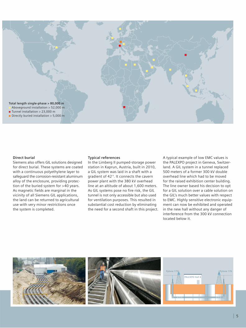
Direct burialSiemens also offers GIL solutions designed for direct burial. These systems are coated with a continuous polyethylene layer to safeguard the corrosion-resistant aluminum alloy of the enclosure, providing protec-tion of the buried system for >40 years. As magnetic fields are marginal in the vicinity of all Siemens GIL applications, the land can be returned to agricultural use with very minor restrictions once the system is completed.
Pylone 175 Pylone 176
PALEXPO Hall 6
Typical referencesIn the Limberg II pumped-storage power station in Kaprun, Austria, built in 2010, a GIL system was laid in a shaft with a gradient of 42 °. It connects the cavern power plant with the 380 kV overhead line at an altitude of about 1,600 meters. As GIL systems pose no fire risk, the GIL tunnel is not only access ible but also used for ventilation purposes. This resulted in substantial cost reduction by eliminating the need for a second shaft in this project.
A typical example of low EMC values is the PALEXPO project in Geneva, Switzer-land. A GIL system in a tunnel replaced 500 meters of a former 300 kV double overhead line which had to be moved for the raised exhibition center building. The line owner based his decision to opt for a GIL solution over a cable solution on the GIL’s much better values with respect to EMC. Highly sensitive electronic equip-ment can now be exhibited and operated in the new hall without any danger of interference from the 300 kV connection located below it.
5
Total length single-phase > 80,000 m ■ Aboveground installation > 52,000 m■ Tunnel installation > 23,000 m■ Directly buried installation > 5,000 m

Minimum effort – optimum resultGIL was developed to meet a wide variety of requirements for installation and oper-ation. A decisive factor in meeting this demand was an installation process that permits assembly of prefabricated mod-ules at the installation site, thus allowing optimum adoption of the selected routing. This concept also has logistic advantages. All elements such as tubes, angles and special modules are lightweight and small enough to be transported by compara-tively light standard trucks.
During installation a major focus is pro-viding gastight connections for the com-ponents. To accomplish this requirement, Siemens employs a computer-controlled automatic welding process. A welding robot ensures the highest precision and reproducibility of the welding seams. The quality of each seam is verified to 100 percent with ultrasonic tests to ensure perfect gastightness and mechanical strength. As a result, no replenishment of insulation gas is needed during the entire service life of > 50 years.
6
GIL – Technical data
Rated voltage 245 to 550 kV
Typical rated current (higher values on request)
up to 4,500 A
Rated short-circuit current 63 kA/3 s
Insulating gas N2 and SF6 mixture
Typical system length 100 m to 100 km
Impulse withstand voltage 1,050 to 1,675 kV
Capacitance 55 nF/km
Overload capacity up to 100% depending on design and requirements
Outer diameter ~375 to 512 mm
Weight per phase 50 kg/m
Coherent concept from design through operation
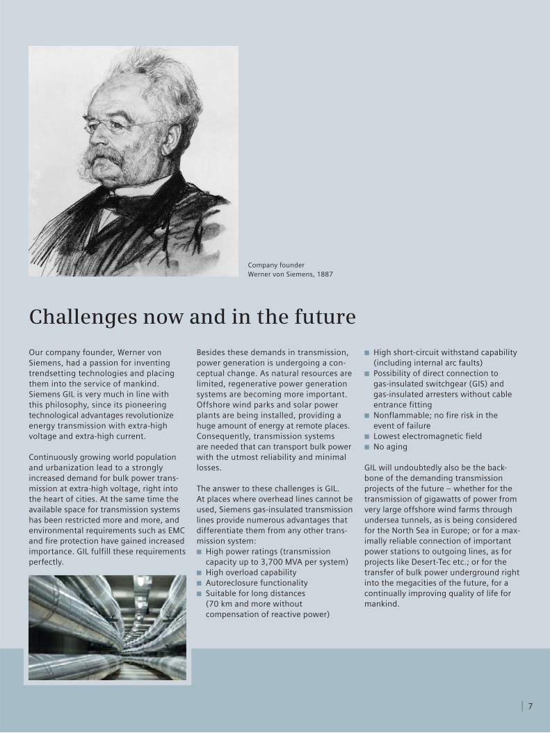
Our company founder, Werner von Siemens, had a passion for inventing trendsetting technologies and placing them into the service of mankind. Siemens GIL is very much in line with this philosophy, since its pioneering technological advantages revolutionize energy transmission with extra-high voltage and extra-high current.
Continuously growing world population and urbanization lead to a strongly increased demand for bulk power trans-mission at extra-high voltage, right into the heart of cities. At the same time the available space for transmission systems has been restricted more and more, and environmental requirements such as EMC and fire protection have gained increased importance. GIL fulfill these require ments perfectly.
Besides these demands in transmission, power generation is undergoing a con-ceptual change. As natural resources are limited, regenerative power generation systems are becoming more impor tant. Offshore wind parks and solar power plants are being installed, providing a huge amount of energy at remote places. Consequently, transmission systems are needed that can transport bulk power with the utmost reliability and minimal losses.
The answer to these challenges is GIL. At places where overhead lines cannot be used, Siemens gas-insulated transmission lines provide numerous advantages that differentiate them from any other trans-mission system:
High power ratings (transmission ■
capacity up to 3,700 MVA per system)High overload capability ■
Autoreclosure functionality ■
Suitable for long distances ■
(70 km and more without compensation of reactive power)
High short-circuit withstand capability ■
(including internal arc faults)Possibility of direct connection to ■
gas-insulated switchgear (GIS) and gas-insulated arresters without cable entrance fittingNonflammable; no fire risk in the ■
event of failureLowest electromagnetic field ■
No aging ■
GIL will undoubtedly also be the back-bone of the demanding transmission projects of the future – whether for the transmission of gigawatts of power from very large offshore wind farms through undersea tunnels, as is being considered for the North Sea in Europe; or for a max-imally reliable connection of important power stations to outgoing lines, as for projects like Desert-Tec etc.; or for the transfer of bulk power underground right into the megacities of the future, for a continually improving quality of life for mankind.
Company founder Werner von Siemens, 1887
7
Challenges now and in the future
www.siemens.com/energy
Published by and copyright © 2010:Siemens AGEnergy SectorFreyeslebenstrasse 191058 Erlangen, Germany
Siemens AGEnergy SectorPower Transmission DivisionHigh Voltage SubstationsFreyeslebenstrasse 191058 Erlangen, Germanywww.siemens.com/energy/hv-gil
For more information, please contact our Customer Support Center.Phone: +49 180/524 70 00Fax: +49 180/524 24 71(Charges depending on provider)E-mail: [email protected]
Power Transmission Division Order No. E50001-G620-A125-V1-4A00Printed in GermanyDispo 30000TH 250-100090 470735 WS 08102.0
Printed on elementary chlorine-free bleached paper.
All rights reserved.Trademarks mentioned in this document are the property of Siemens AG, its affiliates, or their respective owners.
Subject to change without prior notice.The information in this document contains generaldescriptions of the technical options available, whichmay not apply in all cases. The required technicaloptions should therefore be specified in the contract.
© Siemens AG 2015 All rights reserved.Page 1 Henrik Nordenborg / Siemens EM TS 2 PTL SMarch 2015
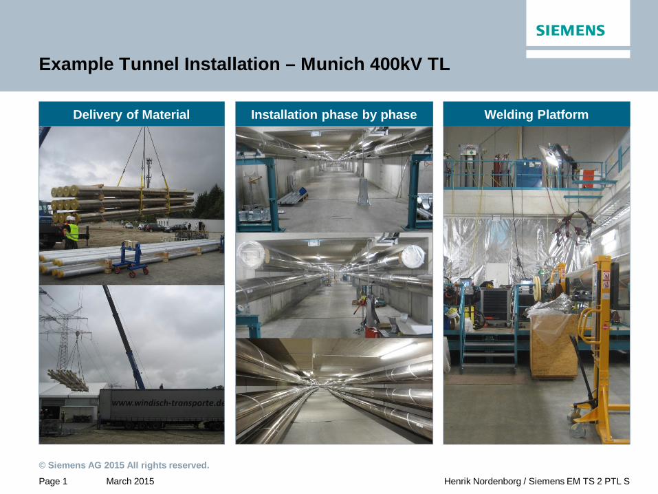
Example Tunnel Installation – Munich 400kV TL
Delivery of Material Welding PlatformInstallation phase by phase