sf 6 in electrical equipment of 1 kv to 52 kv (medium-voltage) · t&d europe sf6 tf 22/03/2011...
TRANSCRIPT
T&D Europe SF6 TF 22/03/2011
Page 1/32
SF6 in electrical equipment of 1 kV to 52 kV (medium-v oltage)
Statement on the review of
Regulation (EC) No 842/2006
of the European Parliament and of the Council according to Article 10 of 17 May 2006
on certain fluorinated greenhouse gases
by T&D Europe
Edition 1.0 March 2011

T&D Europe SF6 TF 22/03/2011
Page 2/32
Table of Contents 0. Summary 1. Introduction
2. Energy efficiency and sustainable use of SF6
2.1 Reduced energy losses 2.2 Trends in medium-voltage switchgear
3. Environmental implication of using SF6 in HVSI 3.1 Actual contribution of SF6 emitted by MV switchgear to the global warming
potential 3.2 Life cycle assessment 3.3 SF6 emission reduction: an achievable worldwide challenge
3.3.1 Key facts 3.3.2 Comparison to the scenario 450 3.3.3 The situation in Europe 3.3.4 Practicable improvements 3.3.5 New prospective for IPCC
4. Main reasons to consider SF6 as a sustainable technology
4.1 Which are the reasons for the applications/advantages of SF6? 4.2 Overview of available switchgear technologies
5. Solutions for control and mitigation of SF6 emissions 5.1 Evolution of the standards including requirements about SF6 5.2 Voluntary agreements for SF6 emission reduction 5.3 SF6 use in closed cycle
6. Europe’s industrial and technological leadership
7. Conclusion
ANNEX A German voluntary agreement brief summary and main results ANNEX B French voluntary agreement brief summary and main results ANNEX C Spanish voluntary agreement brief summary and main results ANNEX D Norway voluntary agreement brief summary and main results ANNEX E Swiss voluntary agreement brief summary REFERENCES
Note: In general, the statements that are formulated for this medium-voltage (MV) related document i.e. 1kV to 52kV, also apply for high-voltage (HV) applications i.e. 52kV to 800kV and above.

T&D Europe SF6 TF 22/03/2011
Page 3/32
0. Summary
We refer to the forthcoming review of Regulation (EC) 842/2006 and would like to reiterate the importance of SF6 as a switching and insulating medium in medium-voltage, high-voltage and very high-voltage switchgear, in Electricity Transmission and Distribution networks. Several years before the Kyoto Protocol entered into force, the entire European electrical energy sector, utilities and manufacturers, together with their associations Eurelectric, and Capiel HV (now T&D Europe), analysed the use and handling of SF6 intensively. Consequently the overall industry implemented the experience and suggestions for improvement from an early stage, with respect to performance, safety and also to the reduction of greenhouse gas emissions. The annual CO2 emissions solely due to ohmic losses in the transmission and distribution grids are one order of magnitude higher than the direct annual emissions from the use of SF6
electrical equipment within EU-15. SF6 insulated electrical equipment thanks to its compact design, allows higher voltage networks to be brought closer to urban consumers thus minimising energy losses associated with the transmission and distribution of electricity. 1.7 Mt CO2 annual emission reductions are achieved thanks to avoided transmission and distribution losses for the installed EU-25+3 banks in 2003 (5000 tons of SF6 installed in HV equipment and 2000 tons of SF6 installed in MV equipment). According to a comprehensive life cycle assessment of transmission and distribution networks, the major part of the CO2 emissions in Transmission and Distribution networks comes from ohmic losses. These could be reduced by implementing projects to increase the voltage in networks close to consumers. If such a development were to be implemented then preference should be given to more SF6 medium-voltage switchgear, particularly to keep compactness of sub-station design to minimise environmental and visual impact.
Furthermore, a comparison of air-insulated (AIS) with SF6-insulated (GIS) technologies shows the advantages of the SF6-GIS technology with regard to primary energy demand, acidification potential (acid rain), eutrophication potential (over-fertilisation) and global warming potential (GWP).
SF6 in medium-voltage equipment contributed only to 0,01% to total EU-15 greenhouse gas emissions in 2002. This proven low impact of SF6 emissions from medium-voltage switchgear amounts to a fraction of the overall emissions and only is a very minor concern.
Therefore, there is no added value in introducing stricter regulatory constraints. Moreover, as the F-Gas Regulation is comparitively recent, it is preferable to consolidate first the implementation of the F-Gas regulation in every Member State and T&D Europe is ready to bring support and contribution. The recent Ecofys study made available in 2010 shows that, at a global level, significant SF6 emission reduction may be achieved even beyond the targets, defined at the Copenhagen conference December 2009, whicht are necessary to stabilize the global warming at an average temperature increase of 2°C. Furthermore it shows that, at global level, a decrease of about 30% of emissions during the complete cycle of manufacturing, use and decommissioning can be expected in year 2030 with respect to emissions in 2005. And this would happen irrespective of forecast growth of SF6 banked in electrical equipment [4]. This reduction is remarkably better that the environmentalists global GHG emission reduction ambition, estimated to be about 12% respect to 2005, necessary to reach a CO2 concentration of 450ppm in the atmosphere.
T&D Europe SF6 TF 22/03/2011
Page 4/32
In this global context it must be noted that the electrical sector in Europe (also in Japan) has already reached what can be considered the technical limits in the mitigation of emissions by application of the highest technical standards. Because of that no major improvements in reduction of emissions can be expected; except those derived from progressive replacement of older, less efficient, equipment by state-of-the-art new equipment. It should also be highlighted that the European manufacturing industry is still continuing step by step to reduce SF6 emissions by pro-active actions and is making indirect contribution to the global improvements by supplying to other countries, equipment and technical assistance. Utilities and other customers will select compact SF6-insulated equipmet when the evaluation of the decisive criteria: environmental-, safety-, reliability- and economic criteria are beneficial to the user’s purpose, taking into account service and prevailing environment conditions at the location of the installation. In order to achieve sustainable solutions, manufacturers and grid operators cooperate in International Standardisation Committees and have succeeded in: 1) New requirements that reduce the maximum permissible leakage rate to < 0.1% p.a. for sealed pressure systems (mainly medium-voltage sealed for life equipment), and < 0.5% for closed pressure systems (mainly high-voltage equipment). 2) Elaboration of recommendations such as reducing the amount of gas pipework or reducing the number of gas connections and flanges, etc., for users and OEM’s to maintain a high level of SF6 tightness, which is essential to avoid SF6 emissions. Voluntary agreements have been signed in different countries with their respective local Environmental Protection Agencies and a periodic follow-up is organised. This proves the electrical sector’s commitment to environmental protection and to the fight against climate change. In that sense the European exporters are prepared to provide the necessary technical support to the non-OECD countries to implement the technical and organisational measures that will allow them to also reach the optimal level. We would also like to comment on the fact that SF6 is used in a closed cycle system in order to avoid emissions into the atmosphere. The so called re-use concept, founded on international standards, has been put in place, allowing the re-use of SF6. 1. Introduction Participation of the European energy technology ind ustry During the first half of twentieth century the main technologies used in switchgear for switching and insulation were air and oil. However, these were characterised by a global low performance capacity, high material consumption in relation to performance and thus ineffective use of resources, use of materials and substances that were progressively rejected for technical, ecological and safety related reasons, as well as poor reliability. The nineteen seventies saw the appearance of new, more efficient technologies, among them SF6 technology. To be broadly used, this new technology had to be thoroughly analysed and validated including assessment of its technological impact, and possibilities of implementation in production terms. Since the early nineteen nineties and thus before the Kyoto Protocol entered into force (2005-02-16), the European energy technology industry has intensively analysed the use and handling of sulphur hexafluoride (SF6) and has contributed and implemented its experiences and improvement suggestions from an early stage, not only with respect to performance and

T&D Europe SF6 TF 22/03/2011
Page 5/32
safety, but also with respect to the reduction of greenhouse gas emissions. Between 1991 and 1995 the principal focus was on safety. Since 1995 when the GWP of SF6 was calculated and published, the European industry enrolled in taking voluntary actions to reduce emissions in each phase of service life of SF6 switchgear, with very significant positive results. At the same time, in cooperation with grid operators, technical documentation was prepared and made accessible in order to ensure the implementation of best practices in the use and handling of SF6 in HV and MV switchgear. This is reflected, among other things, in numerous international documents and standards on SF6 in electrical equipment. In particular, requirements concerning recovery, training and certification as well as reporting and identification go beyond the requirements of Regulation (EC) No. 842/2006 [1], meeting the highest European requirements since the coming into effect of IEC TR 62271-303: High-voltage switchgear and controlgear - Part 303: Use and handling of sulphur hexafluoride (SF6) [2]. Other international standards fix very low emission rates for the different pressure systems used in the electrical industry (See section 5.1 of this paper) National training and certification systems, as required by the European Regulation, have already been implemented by some Member States, namely Germany, Netherlands and United Kingdom. In the remaining countries of the EU, Member States are currently in the process of implementing the requirements of the existing Regulation.. Cooperation by the Manufacturers with the respective authorities is open and target-oriented. However it must be noted that all operators currently performing tasks concerning handling of SF6, even if not certified yet by appropriate Member States, are already trained by their respective companies following training documentation and procedures described in IEC TR 62271-303. As of November, 30th 2010 at least 1348 people have been already trained and certified with respect to recovery according to Regulation (EC) No. 305/2008 [3]. For example, in Germany alone, people from 18 EU member states have been trained and certified with respect to recovery since Regulation (EC) No. 305/2008 came into force on 1 July 2009. In the Netherlands, 126 people have been trained and certified during the same period. In addition to this, in some European countries such as France, Germany, Norway, Spain and Switzerland, the electrical sector has signed with the respective national Environmental Protection Agencies, Voluntary Agreements in order to reduce SF6 emissions 2. Energy efficiency and sustainable use of SF 6 2.1 Reduced energy losses Due to the physical properties of SF6, SF6 insulated electrical equipment embrace safety and reliability in a compact design and hence may enable transmission and distribution grid structures to be designed differently. This would allow modern grids to benefit from a higher voltage level which can be brought more effectively, and safely, closer to urban consumers, reducing the ohmic losses. This is favourable to network capacity dimensioning as it minimises energy losses associated with transmission and distribution of electricity. At the same time, ohmic losses within the electrical equipment are also reduced due to their more compact design. A study elaborated by ECOFYS and published in 2005 [4] presented an example of calculation of the reduction of energy losses in the HV grid as an indirect effect of SF6-insulated equipment. According to this study, in HV applications 1 ton of installed SF6 would save 0.8 GWh of transmission and distribution losses of electricity per year and in MV applications 1 ton of installed SF6 would save 0.2 GWh per year. Applying the EU-15

T&D Europe SF6 TF 22/03/2011
Page 6/32
generation mix value of 0.35 kg CO2/kWh (EURELECTRIC, 2004), one obtains emission reductions from decreased transmission and distribution losses of SF6 of roughly 1.7 Mt CO2 annually for the installed EU-25+3 banks in 2003 (5000 tons of SF6 installed in HV equipment and 2000 tons of SF6 installed in MV equipment). 2.2 Trends in medium-voltage switchgear For medium-voltage applications, another trend should concern the increase of the voltage in networks. The major part of CO2 emission comes from ohmic losses. As now CO2 emission is at stake, there are thoughts and projects to increase the voltage in the network to reduce ohmic losses. Let us just take the example of wind towers. For sure, the efficient voltage level in these windfarm applications is 36 kV. A general evolution, based on electrical utilities forecast and consolidated by T&D Europe experts can be summarized as shown in Figure 1
Proportion of switchgear per level of voltage
0%
10%
20%
30%
40%
50%
60%
Year 2010 Year 2020 Year 2030
10kV
20kV
30kV
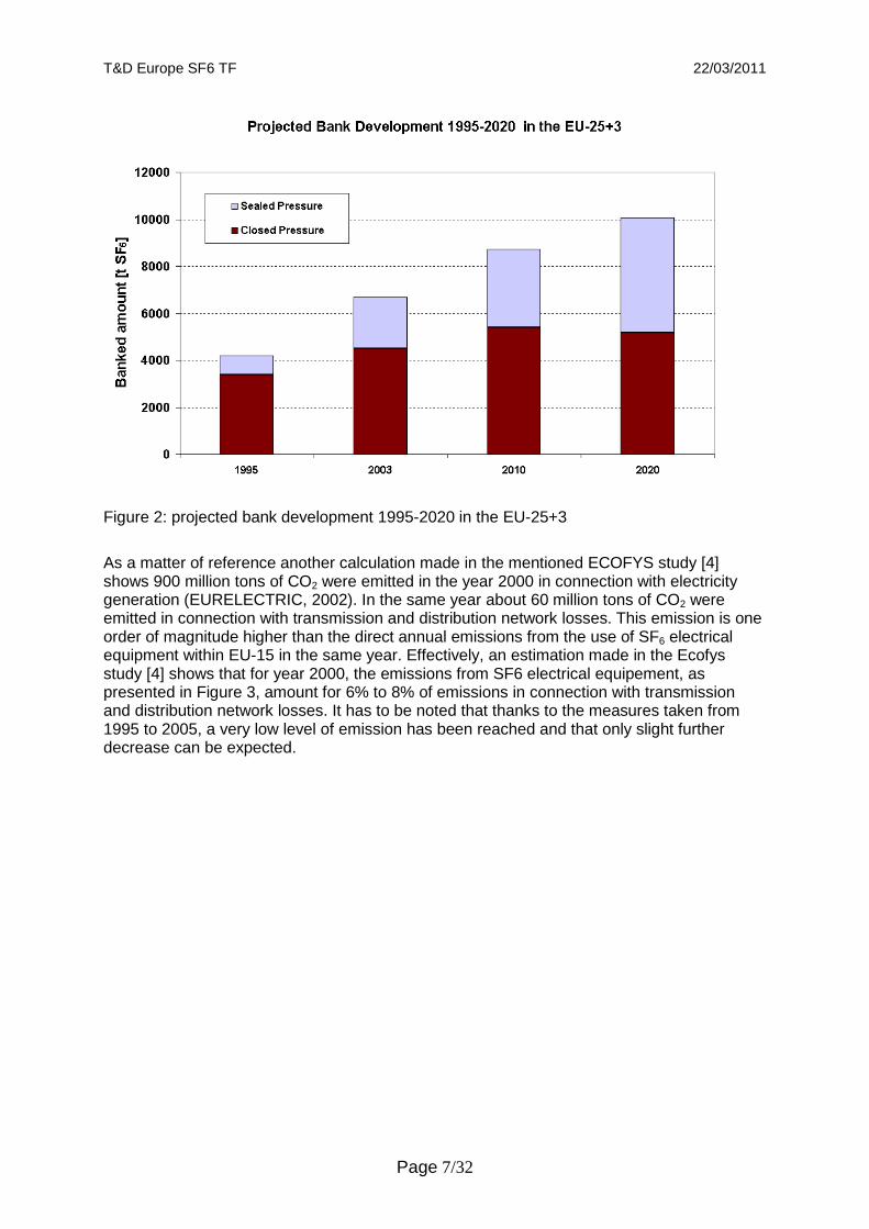
Figure 1: Evolution of the proportion of MV switchgear from 2010 to 2030 Due to this increase in network voltage, and as explained before, due to the non-availability of switchgear with same functionalities (compactness, insensitivity to the environment, safety, cost-effectiveness and reduced environmental impact), preference should be given more to SF6 medium voltage switchgear. Bank and emission development The same Ecofys study (2005) [4] estimates the bank development resulting from the expert survey (Figure 2).
T&D Europe SF6 TF 22/03/2011
Page 7/32
Figure 2: projected bank development 1995-2020 in the EU-25+3
As a matter of reference another calculation made in the mentioned ECOFYS study [4] shows 900 million tons of CO2 were emitted in the year 2000 in connection with electricity generation (EURELECTRIC, 2002). In the same year about 60 million tons of CO2 were emitted in connection with transmission and distribution network losses. This emission is one order of magnitude higher than the direct annual emissions from the use of SF6 electrical equipment within EU-15 in the same year. Effectively, an estimation made in the Ecofys study [4] shows that for year 2000, the emissions from SF6 electrical equipement, as presented in Figure 3, amount for 6% to 8% of emissions in connection with transmission and distribution network losses. It has to be noted that thanks to the measures taken from 1995 to 2005, a very low level of emission has been reached and that only slight further decrease can be expected.

T&D Europe SF6 TF 22/03/2011
Page 8/32
Figure 3: Emission Projections 1995-2020 in the EU-25+3 3. Environmental implication of using SF 6 in HVSI 3.1 Actual contribution of SF 6 emitted by MV switchgear to the global warming potential There are different sources evaluating the emissions of F-Gas and their relative contribution. The results from all these studies are quite similar and show that emissions from electrical sector are very low and that their relative contribution compared to other gases also are very low. Firstly, it is well known, as shown in Figure 4, that the distribution across the different fluorinated gases is dominated by HFCs (Ecofys study – 2005 [4]).
Figure 4: Distribution of total EU-15 greenhouse gas emissions in 2002 broken down into individual greenhouse gases

T&D Europe SF6 TF 22/03/2011
Page 9/32
According to Member State greenhouse gas inventories prepared following IPCC guidelines [5], the fluorinated gases, i.e. hydrofluorocarbons (HFC), perfluorocarbons (PFC) and SF6,
contributed less than 2% to total EU-15 greenhouse gas emissions in 2002. Emissions of fluorinated gases are dominated by HFCs, which are used as substitutes for ozone depleting substances, while SF6
contributed a smaller share of 14% to total emissions from fluorinated
greenhouse gases. For 2002, it is estimated that SF6 contributed only to 0.2% of total EU-15 greenhouse gas emissions (EEA, 2004). Assuming that the division of SF6 emissions between HV and MV in EU-15 amounts to 95% and 5% respectively, as was the case in Germany in 2009, the contribution of SF6 provided by MV in EU-15 amounts to 0.01%. 3.2 Life cycle assessment A comprehensive life cycle assessment of transmission and distribution networks demonstrates the environmental advantages of SF6 gas insulated switchgear (GIS) compared to air-insulated switchgear (AIS) [6]. The switchgear as a component in the grid , however, only makes a very minor contribution to global warming potential. The design and capacity utilisation of the power distribution grids have a much greater influence, regardless of whether AIS or GIS technology is used. Therefore, bans and application restrictions on the use of SF6-insulated medium-voltage switchgear implicate focus on sub-optimalisation and cannot be justified from an environmental management point of view. Consequently, regulations aimed at switchgear and components is deemed to fail making significant contribution towards climate protection. Rather, from a system point of view, grid operators, for whom in addition, other criteria are predominant, such as safety to person, security of installation, reliable energy supply and economic efficiency, should be able to perform proper environmental management and to choose a best for the purpose solution when selecting switchgear technology. Results of the life cycle assessment The system approach was used to carry out the life cycle assessment to evaluate the contribution made by distribution grids to the global warming potential (GWP). It shows that the greatest share is attributable to ohmic losses in cables, transmission lines and transformers. At present, it can be estimated that SF6 emissions from medium-voltage switchgear contribute less than 0.01% to the global warming potential in Europe. An LCA was conducted, based on data of the German distribution network. However, the results of this life cycle assessment can be transferred, in principle, to other European countries. A sensitivity analysis shows that the selection of primary energy carriers used for electricity generation, as the most significant regional factor, only has a minor effect on the results. The following conclusions can be drawn from the results of the life cycle assessment: ● The system approach on grid level is indispensable to obtain meaningful results. On the one hand, it confirms that the total contribution of power distribution grids to the global warming potential is very low. On the other hand, ohmic losses are clearly identified as the main determinant of this contribution to global warming potential. Consequently, the differences between the switchgear technologies are marginal compared to the significant ohmic losses from cables, transmission lines and transformers. For this reason alone, regulations aimed at switchgear will not accomplish any relevant climatic protection potential. ● However, if a detailed investigation is made at switchgear level, a comparison of air-insulated (AIS) and SF6-insulated (GIS) technologies shows the advantages of the SF6-GIS technology with regard to primary energy demand, acidification potential (acid rain), eutrophication potential (over-fertilisation) and global warming potential (GWP). This finding of this LCA shows the critical importance of conducting any comparison of environmental

T&D Europe SF6 TF 22/03/2011
Page 10/32
impact using a “system approach” instead of a simplistic, limited “substance approach”. In this particular case, the intuitive “substance approach” would reach the conclusion that air insulation should be a “greener “option. However the objective “system approach” proves the opposite, avoiding a possible dangerous wrong environmental decision. ● It has been shown [Figure 5] that the determining factors impacting on the global warming potential are in fact the electrical loads in the grid and the switchgear. The current trend towards higher capacity utilisation of the grids increases the advantages of SF6-insulated switchgear. Thus, to accomplish any significant climatic protection potential, it would appear that load management in grids would be more promising than a further optimisation of switchgear design.
Figure 5: Contribution to global warming potential of an urban power distribution grid [6] When the total global warming potential (GWP) of a representative urban distribution grid is considered, the switchgear only makes a minor contribution. Rather, other grid components such as cables and transformers play a decisive role regardless of whether AIS or GIS technology is used. The Figure 6 shows an overview of the environmental impact categories that were examined in the study at switchgear level. It is based on a representative mix of all switchgear types in the medium-voltage range on the basis of a ZVEI delivery statistic. Clear advantages for SF6-insulated switchgear (GIS) compared to air-insulated switchgear (AIS) are also shown with regard to global warming potential (GWP).
Figure 6: Comparison between environmental impact of GIS and AIS switchgear

T&D Europe SF6 TF 22/03/2011
Page 11/32
3.3 SF6 emission reduction: an achievable worldwide challe nge 3.3.1 Key facts From the beginning of the use of SF6, the electrical sector started to put in place a framework of standards for its correct use. This pro-active behaviour has been accelerated from 1995 and now every phase of the lifecycle of SF6 switchgear is covered by state-of-the practices keeping SF6 emissions at a very low level. Following these efforts, a European framework of regulations has formalized some of the main best available techniques. A recent study from Ecofys [7] about the emission scenarios for the short and long term has proven that significant SF6 emission reduction may be achieved even beyond the targets defined at the Copenhagen conference December 2009 that are necessary to stabilize the global warming at an average temperature increase of 2°C. Thanks to the experience gained from the implementation of voluntary agreements [8] that have proven to be one of the best tools to reduce SF6 emissions, the T&D Europe manufacturers association is ready to share the best available practices for a sustainable Electricity Transmission and Distribution. The ECOFYS study [7] shows that, at global level, a decrease of about 30% of emissions during the complete life cycle (manufacturing, use and decommissioning) can be expected in year 2030 with respect to emissions in 2005. And this would happen in spite of a very relevant expected increase of the bank development (almost five times more equipment in service than in 2005). In relative terms, it means that the rate of global emission per ton of SF6 banked in equipment in service will decrease from about 5% in 2005 to a mere 0,8% in 2030. 3.3.2 Comparison to the Scenario 450 The so-called “scenario 450” refers to a situation where the CO2 concentration in the atmosphere does not exceed 450ppm. This situation is considered by some environmental experts to be able to prevent the most catastrophic events, derived from the global warming, and it is admitted so in the recent WEO’09 (World Energy Outlook published by the International Energy Agency) That concentration of CO2 in the atmosphere was supposed to increase the temperature of the planet by less than 2 degrees. It sounds even ambitious after Copenhagen COP 15. Comparing the evolution of total GHG emissions in the SCENARIO 450, it can be noted that the trends of the reduction of SF6 emissions from electrical equipment (reduction of about 30%) is remarkably better that the environmentalists global GHG emission reduction ambition, estimated to be about 12% with respect to 2005. In other words, concerning the use of SF6, the electrical industry will keep on being in the forefront of the fight against the global warming. Figure 7 shows some comparative data referred to the “scenario 450” and the conclusions of the Ecofys report [7].
Year 2005 Year 2030 Variation Global CO2 equivalent.(*) 42.200 Mt 37.100 Mt -12.1% Energy related CO2 equivalent(*) 27.000 Mt 26.400 Mt -2.2% SF6 emission (from electrical equipment(**) 1.700 t 1.190 t -30% SF6 in CO2 equivalent.(**) 40,66 Mt 28,44Mt -30% % SF6/GHG Global 0.096 0.077 -19.8% % SF6/GHG energy 0.15 0.11 -26.7&
(*) figures extracted from the WEO’09 (**) figures extracted from the Ecofys report “Update on global SF6 emissions, trends from electrical equipment”

T&D Europe SF6 TF 22/03/2011
Page 12/32
Figure 7: SF6 emission reductions compared to Scenario 450 3.3.3 The situation in Europe Considering only Europe and Japan, the electrical sector has already reached what can be considered as high technical standards in the mitigation of SF6 emissions. At European Union level, on top of a legal frame that limits the emissions (Regulation EC 842/2006), there are a number of voluntary agreements [8], [Annexes B to F], in different countries, signed by the concerned entities (government, gas producers, manufacturers, users, decommissioning entities) to enhance the efforts to reduce emissions. These agreements have proven to be a flexible and efficient tool to achieve environmental improvements. 3.3.4 Practicable improvements In Europe and Japan no major improvements in the emissions limitation can be expected in absolute terms, in the coming years. However, a decrease of the emission rate per ton of SF6 installed can be still expected as old equipment at end of life is replaced by state of the art equipment having less SF6 volume, as well as lower leakage rates. The major improvements can be expected in other areas, starting with USA and China together with other countries, especially non-OECD countries, where there are still a lot of work to be done in order to reach the same level of consciousness and good management of SF6 as in Europe and Japan. The switchgear industry has to adapt to the European and Japanese technological steps forward in manufacturing, use and decommissioning. Almost 70% of the increase of electricity demand will happen in the non-OECD countries where there is a lot of room for improvement. The European manufacturing sector is selling state of the art equipment to those countries and will assist them in making a significant contribution on their emissions reduction during the use and decommissioning process. In that sense the European exporters are prepared to provide the necessary technical support to these non-OECD countries to implement the technical and organizational measures that will allow them to reach the optimal level by 2030. 3.3.5 New prospective for IPCC Prospective SF6 emissions figures will be reduced by a factor of at least 10 compared to the figures currently under consideration by IPCC. In year 2030, IPCC SRES emission scenario (1999) assumes 14kT of SF6 emission in a scenario with rapid economic growth, while the new study [7], based on common good practices, claims only 1.2kT. As the process moving towards the Fifth Assessment Report is launched, it is important to highlight these more precise and correct figures and to have them taken in account. 4. Main reasons to consider SF 6 as a sustainable technology 4.1 Which are the reasons for the applications/adva ntages of SF 6? Criteria for the selection of switchgear and device s in energy transmission and distribution > 1kV Different technologies are applied in the energy transmission and distribution of a voltage range greater than 1 kV to fulfil the numerous tasks of the energy supply for the society and industry.

T&D Europe SF6 TF 22/03/2011
Page 13/32
In addition to the SF6 technology, other established technologies (e.g. equipment insulated with air, solids or oil) are offered by manufacturers and implemented by the operators. The operators decide on the respective technology to be applied, considering also other criteria which are provided in an overview below. The different technologies compete in the market on environmental, technological and economic basis. Any particular technology or design is specified, selected and used by the operators after the assessment of the following criteria, which have to be evaluated in terms of investments regarding an overall optimisation: Techno-economic criteria
• System/grid optimisation considering also grid transmission losses • Ambient conditions at the installation location • Existing/available space at the installation location • Flexibility regarding location selection • Simple assembly and operation • Storage
Factors determining life cycle costs
• Investment including costs of land and buildings • Maintenance requirements • Service life • Failure risk/availability • Disposal and/or recycling
Ecological criteria, sustainability
• Holistic ecological review of all emissions at system and equipment and/or field level • Demand for usable and sealed surfaces • Route of overhead lines and cables • Re-usability, recycling and disposability
Safety for the general public
• Personal safety • Fire load • Electromagnetic fields • Acoustic emissions • Supply reliability
Industrial safety
• Personal safety for company staff • Training requirements • Electromagnetic fields
Compact SF6-insulated equipment is used if the evaluation of relevant criteria clearly provides environmental-, safety-, reliability- and economic benefits against other technologies. The properties of SF6-insulated equipment listed below, for which at present no equivalent substitute is available in many applications, speak in favour of the use of SF6 in the respective applications:
• High insulating and electric current breaking capacity • Small dimensions of devices and equipment • Insensitive to ambient conditions • Sustainable use of equipment

T&D Europe SF6 TF 22/03/2011
Page 14/32
• Low interference liability, low failure risk • High personal safety • Low fire load • Reduced energy losses at system and equipment and/or field level
4.2 Overview of available switchgear technologies High voltage withstand capability of the insulation, and excellent arc quenching properties, needed for switching, are prerequisites for the basic operation of switchgear. Research into switchgear technology over the last 100 years has led to an evolution of technologies used. The choice of the media affects the characteristics of the switchgear such as compactness, lifetime, reliability, wear and maintenance costs. A short overview of the insulation available and used as well as switching media is given below. Air is a medium which can be used both for switching and insulation. In circuit-breakers, compressed air was used which entailed a considerable power consumption for the function of compressing and produced unacceptably high noise levels. It is used for insulation today. Of all the available media, the use of air alone for insulation results in the least compact equipment. Oil has better insulation properties than air, but has the problem of flammability and environmental pollution. Oil is still used in selected applications, e.g. transformers or some RMUs. Both oil- and compressed air circuit breakers are no longer produced in the EU-25+3, but such products manufactured during the 1960s and 1970s are still in service. For insulation purposes, polymeric materials were also widely used, but have been replaced in many applications by SF6 insulation, due to extensive maintenance required. Its application does not cover the full range of service voltages in the distribution networks. In the voltage range between 1-52 kV, vacuum was introduced for circuit-breaking in the late 1960s. Today, both vacuum and SF6 are widely used for circuit-breaking in this voltage range. Gas-insulated switchgear using SF6 for both insulation and circuit-breaking has been in service since the 1960s, establishing itself first in the high-voltage range, i.e. above 52 kV, and more than a decade later also in medium-voltage (MV) applications, including the voltage range of 1-52 kV, after positive experience in the high-voltage area was evident. Its main advantages compared with other technologies are very good dielectric, thermal and arc quenching properties and non-flammability. The excellent dielectric properties of SF6 allow high-voltage equipment to be constructed using only 10-20% of the volume/space required for those with air insulation. In the voltage range above 52 kV, SF6 is the state-of-the-art arc-quenching medium used in circuit-breakers. The Figure 8 gives an overview of switching and insulating media typically manufactured today in the EU-25+3. Switching and insulation media can be combined, e.g. at medium-voltage, vacuum or SF6 unit for circuit-breaking can be combined with air or SF6 for insulation.
Voltage level Switching media Insulation media Circuit-breaking Load-breaking
High-voltage SF6 N.A. SF6, air Medium-voltage Air, oil, SF6,
vacuum Air, oil, SF6, vacuum, hard gas
Oil, SF6, air, solids
Figure 8: Insulating media in electrical switchgear Depending on the combination of insulation media, SF6-free switchgear existed for long time and still exist but these SF6-free alternative technologies would have to operate with less efficient gases, at higher equipment cost and this would involve stressing the material at increased risk to safety, without lowering the total environmental impact [6].On the other hand, the manufacturers using SF6 technology have acted and continue acting step by step
T&D Europe SF6 TF 22/03/2011
Page 15/32
to reduce SF6 emissions by proactive actions in design and manufacturing, in the field of standardisation and through the implementation of voluntary agreements [8], [Annexes B to F]. In addition to this, a number of R&D projects have been carried out in recent years by the electrical industry and universities, seeking for alternative solutions that could be implemented in industrial applications covering the complete range of MV distribution voltages and any environmental service conditions prevailing at the installation site. For the time being none of these projects have been successful. So alternative highly efficient new dielectric and arc quenching media are still not in sight today. A new solution, if found at all, would have to be thoroughly analysed and validated and undergo assessment of its technological impact and possibilities of implementation in production terms. 5. Solutions for control and mitigation of SF 6 emissions 5.1 Evolution of the standards including requiremen ts about SF 6 A comprehensive set of international standards has been compiled and will be further developed and continually reconciled with the current state of the art in order to regulate all the different aspects regarding the use of SF6. The electrical sector has been continuously working with CIGRE and standardisation organisations to look for further improvements and to formalise the best practices: 1) First published in 1971 and revised in 2005, IEC 60376 [9] defines the quality requirements and properties for technical grade sulphur hexafluoride (SF6) for use in electrical equipment. It covers the properties and methods of test applicable to SF6 when this substance is supplied for use in connection with electrical equipment. 2) Soon after, from 1974 and revised in 2004, IEC 60480 [10] defines requirements for the recovery and the recycling of the SF6 gas. It also covers switchgear maintenance and end-of-life. It is important to take all dispositions to avoid problems. This standard recommends procedures for checking and treatment of used SF6 and specifications for its reuse for banking in switchgear. For researchers and scientists, this standard is important to advise them which precautions they have to take when they carry out tests on used SF6. 3) IEC 62271-1 Ed 1.0 2007 (former IEC 60694) [11] has lowered the level of leakage rates according to state-of-the-art product design. Constantly applying best available design techniques has made it possible in recent years to refine the tightness requirements in IEC standards. The maximum permissible design leakage rate is now < 0.1% p.a. for sealed pressure systems (mainly medium voltage sealed for life equipment), and < 0.5% for closed pressure systems (mainly high voltage equipment). 4) Regarding SF6 handling, important work has been done under the umbrella of CIGRE (International Council on Large Electric Systems), being one of the leading worldwide scientific and technical organisations on electric power systems. The result of the CIGRE working group was the publication of a guide for the preparation of customised practical SF6 handling instructions in August 2005 [12]. 5) As it is of quite common practice, the above mentioned guide was used as a basis for preparation of the IEC Technical Report 62271-303 Use and Handling of SF6 in 2008 [2]. It is a technical revision of IEC TR 61634 edited in 1995 covering mainly safety issues , based on a document prepared by CAPIEL (European Association of HV switchgear manufacturers , predecessor of the current T&D EUROPE). IEC TR 62271-303 document explains procedures for the safe and environmentally compatible handling of SF6 during installation, commissioning, normal and abnormal operations, and end-of-life disposal of HV switchgear and control gear. Storage and transportation of SF6 are also covered.

T&D Europe SF6 TF 22/03/2011
Page 16/32
One chapter is dedicated to training and certification, because adequate training is one of the best ways of minimising SF6 emissions during all handling operations. Particular attention is paid to decommissioning. It is recommended to recover SF6 up to a residual pressure in the gas compartment of 2kPa. This can now easily be achieved with modern devices. Portable devices are able to analyse the recovered gas to facilitate the procedures for reclaiming before re-use. Proper SF6 handling at decommissioning will be a major improvement to reducing SF6 emissions. This technical report is currently under revision to become the future international standard IEC 62271-4 Use and Handling of Sulphur Hexafluoride (SF6), including several informative appendices (Forecast publication date : 2011-12 ). The main interest of the move from a Technical Report to an International Standard is that the value of the document is increased and it can be used more widely and drawn on as a point of reference in various regulations and directives. It could become the link between technical experts from the electrical sector and policy makers with the common objective of reducing SF6 emissions. 6) More recently, another CIGRE working group B3 AA2 WG18 has prepared the SF6 Tightness Guide [13] [Technical brochure 430 B3.18 2010]. State-of-the-art electric power equipment is designed and manufactured to maintain integrity and tightness for decades so that it is compatible with the environment for its entire operational life. The guide reviews all significant aspects of the tightness of electric power equipment containing SF6. An important part is dedicated to state-of-the-art test procedures, test methods and instruments used. Type-testing, factory routine testing and on-site testing during service are described. Type-testing procedures are mainly based on some of the methods described in the standard IEC 60068-2-17 [14]. Continuous on-line monitoring is also included. Recommendations such as reducing the amount of gas pipework or reducing the number of gas connections and flanges, etc. are given to users and OEMs so as to work towards maintaining a high level of SF6 tightness, which is essential to avoid SF6 emissions. 5.2 Voluntary agreements for SF 6 emission reduction Member companies of T&D Europe, grid operators, gas manufacturers and all other actors such as electricity distributors or gas manufacturers have signed voluntary agreements in some European countries such as Germany [Annex A], France [Annex B], Spain [Annex C], Norway [Annex D] and Switzerland [Annex E]. They have been signed with their respective local Environmental Protection Agencies and a periodic follow-up is organised. This proves the electrical sector’s commitment to environmental protection and to the fight against climate change. These voluntary agreements set up concrete targets for SF6 emission reduction within a certain period of time. Examples of results of the implementation of voluntary agreements are shown in Annex A to E. Continuously decreasing emissions indicate that the current regulation (EC) No 842/2006 together with suitable Voluntary Agreements are effective and appropriate. Furthermore this is due to the improved measures of the T&D industry:
- Developing awareness among stakeholders with standards, information provided by the associations
- Further development of SF6-handling equipment - Reduction of the applied gas amount due to technological progress - Improved tightness of containers - Continuous development of the reporting system in Europe (EC) No 842/2006
(Article 6) - Although the standard value of 0,1% is generally applied in the national reporting
systems, the real emissions from MV SF6 switchgear in service are actually even lower than 0,1% per year. Such very low level cannot in practice be verified at the installation site. However the gas tightness tests of today’s state of the art MV
T&D Europe SF6 TF 22/03/2011
Page 17/32
equipment have shown that the real amount of emissions is far below the reference value of the international standard.
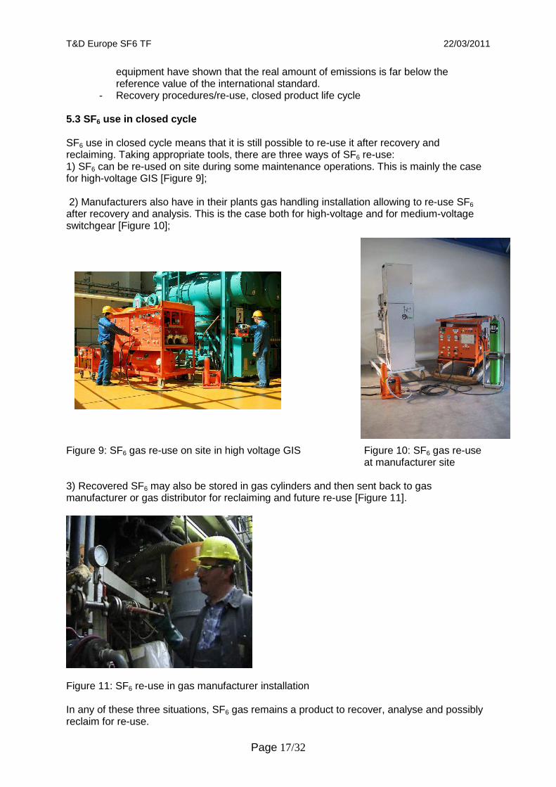
- Recovery procedures/re-use, closed product life cycle 5.3 SF6 use in closed cycle SF6 use in closed cycle means that it is still possible to re-use it after recovery and reclaiming. Taking appropriate tools, there are three ways of SF6 re-use: 1) SF6 can be re-used on site during some maintenance operations. This is mainly the case for high-voltage GIS [Figure 9]; 2) Manufacturers also have in their plants gas handling installation allowing to re-use SF6 after recovery and analysis. This is the case both for high-voltage and for medium-voltage switchgear [Figure 10]; Figure 9: SF6 gas re-use on site in high voltage GIS Figure 10: SF6 gas re-use
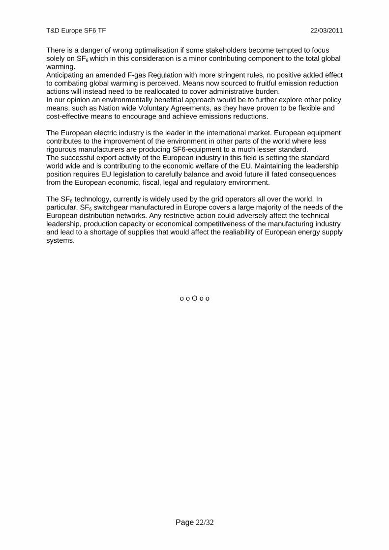
at manufacturer site 3) Recovered SF6 may also be stored in gas cylinders and then sent back to gas manufacturer or gas distributor for reclaiming and future re-use [Figure 11].
Figure 11: SF6 re-use in gas manufacturer installation In any of these three situations, SF6 gas remains a product to recover, analyse and possibly reclaim for re-use.

T&D Europe SF6 TF 22/03/2011
Page 18/32
First steps are to recover and analyse the gas as shown in Figure 12. When starting the decommissioning of SF6 switchgear, the gas may be removed at site or at a specialized plant depending on the transportation possibilities. Generally, SF6 is removed at site for high-voltage switchgear. For medium-voltage switchgear it may be removed at site or at specialized plant. Then the gas is analyzed.
Figure 12: Process of recovery and analysis of SF6 Depending on the results of the analysis, SF6 may be re-used either directly or after reclamation according to IEC technical grades as shown in Figure 13. To evaluate the possibility to reclaim, some criteria such as decomposition products, SF6 volume percentage or dew point temperature are considered. In some rare cases, SF6 is not reclaimable and has to be destroyed by burning process.
Decommissioning of SF 6 filled Electrical Equipment
SF6 removal on site Transport of SF 6 filled
equipment
Transport of used SF 6 to the analysis location e.g.
gas manufacturer
SF6 removal at central place e.g. manufacturers site
SF6 gas analysis according to IEC 62271-303

T&D Europe SF6 TF 22/03/2011
Page 19/32
Figure 13: Process for re-use of SF6 6. Europe’s Industrial and Technological leadership Safeguarding jobs in Europe The Transmission & Distribution (T&D) manufacturing industry in Europe employs more than 200,000 staff, accounts for a production worth over € 25 billion and is currently the world leader in SF6 technology. 30,000 jobs are related to SF6 technology, 15,000 of those jobs are related to medium-voltage switchgear (Ecofys-Study [4]). The European electrical industry in particular is and always has been recognised by experts to be pioneers in terms of climate protection and the implementation of a variety of guidelines. It was on our initiative that open discussions with European authorities and institutions started at an early stage. Marking, recycling and training are meanwhile part of the European Regulation. However, an investment backlog and the uncertainty of national and international markets in times when the effects of the financial and economic crisis are still noticeable, impose further constraints on Europe's industry. This industry’s considerable success in exports due to its technological advantage will suffer in the foreseeable future from the signalling effects of the European fundamental debate of principles and the competitiveness of the European industry would be impaired on an international scale. The electrical industry has carried out, as described above, its activity following proven good environmental practices since 1995, and reaching remarkable SF6 emission reductions. The Regulation, formalising these practices, has the positive effect of ensuring that this trend will continue in the future. Taking this into account the Regulation does neither need to establish new requirements nor implement any specific additionally measure to be adopted by the sector to improve the situation. Any stricter regulation would be disproportionate in view of the low proportion of involvement in the greenhouse gas problem and would provide no measureable contribution to solve the problem.
Direct Re-use
SF6 gas analysis according to IEC 62271-303
SF6 quality specification
according to IEC 60480
YES
NO Contact manufacturer
or Gas supplier: Is SF6
reclaimable?
YES
Re-use after Reclamation to
IEC 60376 or IEC 60480
Final Disposal
NO

T&D Europe SF6 TF 22/03/2011
Page 20/32
Even more, it would be unnecessary, as the voluntary actions of the industry and the Voluntary Agreements existing in some countries have proven to be an efficient and cost-effective procedure to limit the emissions as required by the F-gas regulation.
T&D Europe, as international manufacturer’s association is of course, extremely concerned about the future of European locations (R&D and manufacturing facilities), in view of a new debate on principles. It is important to avoid members moving to other locations outside Europe, taking with them their technology and production. European manufacturers of SF6 HV (above 52kV) switchgear are currently leaders in the international market. The same applies in the medium-voltage domain, where besides major enterprises such as ABB, Schneider Electric, Ormazabal and Siemens, other small- and medium-sized companies would also be affected.
The proven low impact of SF6 emissions from medium-voltage switchgear on the greenhouse potential amounts to a fraction of the overall emissions and stands in no relation to measures that would endanger a great number of jobs by introducing stricter trade barriers for SF6 in electrical equipment. The overall impact on Europe and European industrial activities of such a step backwards is impossible to predict.
Reduction of gas used in medium-voltage application s In the medium-voltage range, the amount of SF6 used per functional unit was continuously reduced by design-related measures. Together with the improved tightness of containers, this has led to a distinct reduction of the specific emissions. See also the following examples of some manufacturers [15]:
Manufacturer 1: a) Switchgear with circuit-breaker feeder 24 kV, 16 kA, 2000 A busbar current;
single busbar, taking an average 630 A feeder as an example: Switchgear type 1, 1998: 100% --- switchgear type 2, from 2002: 50% b) Extendable ring main unit
Individual panels: 100% --- new block-type design: 90%
Manufacturer 2: a) Switchgear with circuit-breaker feeder 24 kV, 16 kA, 2000 A busbar current;
double busbar, taking an average 630 A feeder as an example: Switchgear type 1, since 1989: 100% --- switchgear type 2, from 2001: 90%
b) Switchgear with circuit-breaker feeder 24 kV, 16 kA, 1250 A busbar current; single busbar, taking an average 630 A feeder as an example: Switchgear type 1, until 1995: 100% --- switchgear type 2, from 1996: 36%
Manufacturer 3: a) Switchgear with circuit-breaker feeder 24 kV, 16 kA, 2000 A busbar current;
double busbar, taking an average 630 A feeder as an example: Switchgear type 1, until 1995: 100% --- switchgear type 2, from 1996: 60%
b) Switchgear with circuit-breaker feeder 24 kV, 16 kA, 2000 A busbar current; single busbar, taking an average 630 A feeder as an example: Switchgear type 1, until 1995: 100% --- switchgear type 2, from 1996: 55%
Manufacturer 4: 24 kV ring main unit Since 1991: 100% --- from 2000: 93%
Today, the average amount of SF6 used in the medium-voltage range per functional unit has decreased by about 30% for RMU’s and by more than 50% for circuit breaker switchgear compared to the nineties. It has also been possible to considerably reduce the leakage rates by improving the sealing systems: initially up to 1% p.a. to distinctly below 0.1% p.a. today.

T&D Europe SF6 TF 22/03/2011
Page 21/32
Since the advantages for environmental protection which can be achieved by preference of AIS and GIS technology in the medium-voltage range are insignificant, air- and gas-insulated switchgear are environmentally competitive. From a more general point of view of environmental impact, any technology, including oil, solid insulation and sealed pressure systems without SF6, are practically equivalent, as all of them have a negligibe impact (see sections 2.2 and 3.1). Therefore, the technology to be used must be kept on being, as today, a free option of the user based on other technical, functional or economical reasons. In addition to the environmental standpoint, further aspects must be considered for the evaluation of alternatives. This was also clearly stated in a letter from the Directorate-General for the Environment of the European Commission to the ECCP Working Group of 12 June 2003 - DG ENV.C.2/JD D(2003) 42117 [17] --> "Amendments to marketing restrictions: In making such proposals, the Commission must ensure that an assessment of alternative substances and technologies has been made which takes into account the safety, impact on human health, technical feasibility, cost-effectiveness and environmental impact of such alternative substances or technologies". 7. Conclusion For a modern european grid able to fulfil the 20-20-20 targets, it is of high importance to keep SF6 technology (sulphur hexafluoride) as a switching and insulating medium in medium-voltage, high-voltage and very high-voltage switchgear. We support and follow the obligations based on the existing F-gas regulation EC 842/2006, and consider that it is delivering its objectives in a satisfactory manner. It is therefore our view that the Regulation does not need amendment or revision with regard to the equipment in use. The electrical sector pro-actively continues to seek means to combat potential emission sources and acts pro-actively to mitigate emissions from SF6. Most of these actions and corresponding outcomes exceed the legal obligations laid down in the F-Gas Regulation, and were in place before the regulation became in force. Up to now considerable reductions have been achieved in Europe and Japan since the nineties of last century. Based on the european good practices, at global level it is expected a reduction of the SF6 emissions from electrical equipment of about 30% by year 2030. This reduction represents a much more important contribution to the global geeenhouse gas emissions reduction than the average required to achieve the target of the so-called 450 horizon (global average reduction of 12%). The electrical sector is working with tight equipment with very low leakage rates. SF6 is used in closed cycles: when it is necessary for maintenance or at switchgear end of life, SF6 is recovered, reclaimed if necessary and then re-used. Life cycle assessments performed on grid level demonstrate the advantage of SF6-technology and show that ohmic losses from the electrical networks are the major contributor to the total greenhouse warming. The environmental impact from SF6 gas emitted from electrical switchgear (above 1kV) is very minute. In particular, emissions from medium-voltage (from 1 kV to 52kV) equipment contributed less than 0,01% to the total greenhouse gas emissions. A comparison of air-insulated (AIS) and SF6-insulated (GIS) technologies shows the advantages of the SF6-GIS technology with regard to primary energy demand and global warming potential. The amount of material used is reduced due to more compact designs and the amount of waste at the end of life is similarly reduced. Alternative technologies would have to operate with less efficient gases or more epoxy, at higher equipment cost and limited applications.
T&D Europe SF6 TF 22/03/2011
Page 22/32
There is a danger of wrong optimalisation if some stakeholders become tempted to focus solely on SF6 which in this consideration is a minor contributing component to the total global warming. Anticipating an amended F-gas Regulation with more stringent rules, no positive added effect to combating global warming is perceived. Means now sourced to fruitful emission reduction actions will instead need to be reallocated to cover administrative burden. In our opinion an environmentally benefitial approach would be to further explore other policy means, such as Nation wide Voluntary Agreements, as they have proven to be flexible and cost-effective means to encourage and achieve emissions reductions. The European electric industry is the leader in the international market. European equipment contributes to the improvement of the environment in other parts of the world where less rigourous manufacturers are producing SF6-equipment to a much lesser standard. The successful export activity of the European industry in this field is setting the standard world wide and is contributing to the economic welfare of the EU. Maintaining the leadership position requires EU legislation to carefully balance and avoid future ill fated consequences from the European economic, fiscal, legal and regulatory environment. The SF6 technology, currently is widely used by the grid operators all over the world. In particular, SF6 switchgear manufactured in Europe covers a large majority of the needs of the European distribution networks. Any restrictive action could adversely affect the technical leadership, production capacity or economical competitiveness of the manufacturing industry and lead to a shortage of supplies that would affect the realiability of European energy supply systems.
o o O o o

T&D Europe SF6 TF 22/03/2011
Page 23/32
ANNEX A
German Voluntary agreement SF6 brief summary and main results
Voluntary Commitment of SF6 Producers, Manufacturers and Users of Electrical Equipment > 1kV for Transmission and Distribution of Electric Power
in the Federal Republic of Germany on SF6 as an insulating and arc extinguishing Medium
May 2005 Main targets:

T&D Europe SF6 TF 22/03/2011
Page 24/32
Achievements During the period 2005 to 2009 the following achievements were archived:
1) The total emissions (Table 1 item 1) were reduced from 22 t in 2004 to 13.6 t in 2009. 2) The emission rate during development, testing and manufacturing(Table 1 item 2)
were reduced by 50% during the period 2004 to 2009. 3) The emission rate during installation and commissioning(Table 1 item 3) was reduced
significantly in the HV sector. The MV sector was already below the target based on the sealed for life technology.
Detailed overview:
Table 1: Detailed overview of main achievements Main results The Figure 14 illustrates the continuous reduction of SF6 emissions since 1998 ([16], page 14).

T&D Europe SF6 TF 22/03/2011
Page 25/32
Figure 14: SF6 emissions in Germany In terms of medium-voltage in Germany, the Figure 15 shows that SF6 emissions are decreasing while the application of SF6 is increasing ([16], page 3).
Figure 15: Evolution of SF6 emissions compared to evolution of SF6 consumption

T&D Europe SF6 TF 22/03/2011
Page 26/32
ANNEX B
French voluntary agreement SF6 brief summary and main results
MEMORANDUM OF UNDERSTANDING ON THE FRENCH VOLUNTARY AGREEMENT TO REDUCE SULPHUR HEXAFLUORIDE EMISSION IN HIGH AND MEDIUM VOLTAGE
SWITCHGEAR AND CONTROLGEAR BETWEEN French industry association for electrical equipment, automation and related services
(GIMELEC) The Department in charge of the management for the power transmission network (RTE)
The Ministry of ecology and sustainable development (MEDD) AND
The Agency for environment and energy management, (ADEME)
Main targets In order to meet the greenhouse gas emission reduction objectives set by France within the scope of the Kyoto protocol and the national programme against climatic changes, the enterprises have recently started talks with the government. Besides methods and means specific to large emitters, several federations or groups of manufacturers representing other emitters (companies not having signed with the administration the voluntary agreement for the reduction of greenhouse gases) have expressed the desire to act with their own means. The Ministry of ecology and sustainable development and ADEME have the same targets. In this context, the French industry association for electrical equipment, automation and related services (GIMELEC)and the power transmission network (RTE), in charge of the management for transmission network, MEDD – Ministry of ecology and sustainable development, and ADEME - Agency for environment and energy management, have decided to join their efforts and establish a lasting partnership, signing a voluntary agreement in August 2004. This Memorandum Of Understanding (MOU), aims at stating precisely the common objectives of GIMELEC, RTE, MEDD and ADEME within the framework of the MOU and the commitments of each partner. Because sulphur hexafluoride gas (SF6), is used for insulation of high and medium voltage switchgear and controlgear, has a high global warming power (GWP), the signatory members undertake to reduce SF6 emissions whenever this is technically and commercially possible during the normal life cycle of items of equipment. MEDD, ADEME and the other signatory members have to implement action plans, which will contribute to a major reduction of the prospective emissions in 2010. This would reduce emissions to their estimated level of 1995, as far as market growth and the technical behaviour of the electrical equipment would remain stable during this period. In particular, the Best Available Technologies (BAT) will be used in the development, production, service, maintenance and end of life of switchgears and controlgears in electrical substations. This applies to transportation, as well as to the storage of SF6, and its use, handling, treatment in compliance with use specifications or its elimination to ensure a closed cycle of use They are also committed to promoting this reduction of emissions inside their national professional organizations and all institutions dealing with SF6. Taking into account the industrial structure of this sector and the context, (see annex 2), it is acknowledged that the voluntary commitment, compatible and complementary to the laws, is an appropriate measure for a sustainable use of SF6 in switchgear and controlgear in high and medium voltage above 1000 V. Main results: In France, the voluntary agreement has been signed in 2004. SF6 emissions during manufacturing process have decreased by more than 50% between 1995 and 2009.

T&D Europe SF6 TF 22/03/2011
Page 27/32
ANNEX C
Spanish voluntary agreement SF6 brief summary and main results
HISTORICAL BACKGROUND (1990-2007)
Figure 16 Banked SF6 1990-2007 Figure 17 Comparative evolution of emissions 1990-2007
Figure 16. Shows the evolution of banked SF6 in Spain from 1990 to 2007. It can be seen an spectacular growth of 8.5 times. Figure 17. Compares the global emissions estimated under different conditions: Red line: Shows the real emissions reported after the progressive implementation of voluntary actions since 2005 by the industry. Green line: Shows the trend of emissions BAU 2005, it is without voluntary actions. The reduction of emissions reported in 2007 was 8.3t, (About 45%) which proves the effectiveness of the voluntary actions. VOLUNTARY AGREEMENT (2008-2012) Voluntary Agreement between the Ministry of Environment, manufacturers of HV SF6 electrical equipment, represented by SERCOBE – Association of electrical capital goods manufacturers (AFBEL) - the electrical distribution and transmission utilities, represented by UNESA, and Red Eléctrica Española for the limitation of emissions of sulphur hexafluoride (27 March 2008)

T&D Europe SF6 TF 22/03/2011
Page 28/32
ACHIEVEMENTS OF VOLUNTARY AGREEMENT Figure 18 Achievements of voluntary agreement and prospective results The Spanish Voluntary Agreement includes commitments concerning information to users, emission reporting to the Administration and training of personnel involved in SF6 management in all phases of the life cycle (from prototype testing to end of life, including manufacture, installation, operation and service). The main target of the Voluntary Agreement is to save a cumulated 300,000 t of CO2 equivalent in the period of five years of the agreement (2008-2012). The Figure 18 contains the data reported during the two first years (2008-2009) and the projections until 2012. Note. The information of year 2010 is not yet available. It is currently under compilation in order to be included in the Report 2010 that will be elaborated soon, as established in the Voluntary Agreement. As soon as this data become available the graphic will be up-dated correspondingly.

T&D Europe SF6 TF 22/03/2011
Page 29/32
F-GAS REGULATION AND VOLUNTARY AGREEMENT STATISTICS 2006-2012
Figure 19 Evolution Figure 20 Comparative evolution of banked SF6 (MV + HV) 2006-2012 of total emissions 2006-2012
Figure 19 Shows the evolution of banked SF6 in Spain since 2006, broken down into MV (sealed systems) and HV (closed systems)
Figure 20 Shows the difference between the projected emissions without Voluntary Agreement and with Voluntary Agreement (2008 and 2009 are reported data, 2010 to 2012 are current projections). Figure 21 Evolution of ratio (%) emission/banked SF6 Figure 22 Comparative evolution of
2006-2012 banked SF6, total emissions And ratio emissions/banked (base 100 year 2006) Figure 21. Shows the ratio between global emissions and banked SF6 since the adoption of the Kyoto Protocol. This ratio has been reduced by almost 40% in the period, and seems to have reached a limit. Figure 22. Compares the evolution of banked SF6, total emissions, and ratio emissions/banked SF6, taking year 2006 as base 100. It can be seen that in spite of a growth of the banked SF6 above 60% the emission remains practically stable. Consequently the ratio is declining until about 64% of its value in 2006. This positive evolution is mainly due to the implementation of the F-Gas Regulation supplemented by the Voluntary Agreement.

T&D Europe SF6 TF 22/03/2011
Page 30/32
ANNEX D
Norway voluntary agreement SF6 brief summary and main results
Main results
In the case of Norway, the voluntary agreement has been signed in 2002 and in less than ten years, also Norway cut its SF6 emissions from medium-voltage and high-voltage switchgear by more than 50%

T&D Europe SF6 TF 22/03/2011
Page 31/32
ANNEX E
Swiss voluntary agreement SF6 brief summary

T&D Europe SF6 TF 22/03/2011
Page 32/32
REFERENCES [1] “Regulation (EC) No 842/2006 of the European Parliament and of the Council of 17 May 2006 on certain fluorinated greenhouse gases” - “Official Journal” of the 14th June 2006. [2] IEC TR 62271-303 : Use and handling of sulphur hexafluoride (SF6) – 2008. [3] Regulations (EC) 1493/2007, 1494/2007 and 305/2008 from the “Official Journal” of the European Parliament and the Council. [4] REDUCTIONS OF SF6 EMISSIONS FROM HIGH AND MEDIUM VOLTAGE ELECTRICAL EQUIPMENT IN EUROPE, Final Report to CAPIEL, 28 June 2005, Sina Wartmann and Jochen Harnisch, Ecofys GmbH, Landgrabenstrasse 94, 90443 Nürnberg, Germany. Contact: [email protected]. [5] 2006 IPCC Guidelines for National Greenhouse Gas Inventories, CHAPTER 8: OTHER PRODUCT MANUFACTURE AND USE. [6] SF6-GIS-Technology for Power Distribution – Medium Voltage – 2003 ABB, AREVA, EnBW, E.on, RWE, SIEMENS, Solvay Fluor und Derivate, More information: www.solvay-fluor.com. [7 ] “Update on Global SF6 emissions, trends from electrical equipment” – Edition 1.1 – Ecofys – 2010. [8] Voluntary commitment of SF6 producers, manufacturers and operators of electrical equipment > 1 kV for the electric transmission and distribution of energy in Germany regarding the use of SF6 as insulating and quenching gas (2005). [9] “IEC 60376” of June 2005 - Specification of technical grade sulphur hexafluoride (SF6) for use in electrical equipment. [10] ] “IEC 60480” of October 2004 - Guidelines for the checking and treatment of sulphur hexafluoride (SF6) taken from electrical equipment and specification for its re-use. [11] IEC 62271-1 – Common specifications. [12] CIGRE Guide for the preparation of customised practical SF6 handling instructions no 276 –August 2005. [13] SF6 Tightness Guide - Cigre Technical Brochure 430 B3.18 – 2010. [14] IEC 60068-2-17 – Basic environmental testing procedures – Part 2: Tests – Test Q Sealing – 1994. [15] SF6 in MV and HV switchgear, joint statement of the ZVEI and VDN regarding the "Implementation of national climate protection programme for fluorinated greenhouse gases" (2002) position paper of the BMU. [16] SF6 data 2009 on energy transmission and distribution > 1 kV, FNN, VIK, ZVEI and Solvay, 2010. [17] EU Commission DG Environment - ENV.C.2/JD D(2003) 42117 – To ECCP Fluorinated gas working group members – Brussels 12 June 2003.