sez-a12/18/24ar installation manual (bg79s993h01) · 5 5. refrigerant piping work 5.1. refrigerant...
TRANSCRIPT
Air-ConditionersSEZ-A12, A18, A24AR
EnglishINSTALLATION MANUALFor safe and correct use, please read this installation manual thoroughly before installing the air-conditionerunit.
FOR INSTALLER
2
Contents
1. Safety precautions ................................................................................... 22. Selecting the installation location ............................................................. 23. Installation diagram & Accessories .......................................................... 34. Indoor unit installation .............................................................................. 45. Refrigerant piping work ............................................................................ 56. Drainage piping work ............................................................................... 77. Electrical work .......................................................................................... 88. Duct work ............................................................................................... 10
9. Air filter installation ................................................................................. 1110. Test run .................................................................................................. 1311. Maintenance .......................................................................................... 1412. System control (Fig. 12-1) ...................................................................... 15
This Installation Manual describes only for the indoor unit and the connectedoutdoor unit of SUZ series.If the connected outdoor unit is MXZ series, refer to the Installation Manual forMXZ series.
1. Safety precautions
• Please report to or take consent by the supply authority before connectionto the system.
• Be sure to read “The following should always be observed for safety” beforeinstalling the air conditioner.
• Be sure to observe the cautions specified here as they include importantitems related to safety.
• The indications and meanings are as follows. Warning:
Could lead to death, serious injury, etc.
Caution:Could lead to serious injury in particular environments when operated incor-rectly.• After reading this manual, be sure to keep it together with the instruction
manual in a handy place on the customer’s site.
: Indicates an action that must be avoided.
: Indicates that important instructions must be followed.
: Indicates a part which must be grounded.
: Indicates that caution should be taken with rotating parts.
: Indicates that the main switch must be turned off before servicing.
: Beware of electric shock.
: Beware of hot surface.
Warning:Carefully read the labels affixed to the main unit.
Warning:• Do not install it by yourself (customer).
Incomplete installation could cause injury due to fire, electric shock, the unitfalling or leakage of water. Consult the dealer from whom you purchased theunit or special installer.
• Install the unit securely in a place which can bear the weight of the unit.When installed in an insufficient strong place, the unit could fall causing in-jured.
• Use the specified wires to connect the indoor and outdoor units securely andattach the wires firmly to the terminal board connecting sections so the stressof the wires is not applied to the sections.Incomplete connecting and fixing could cause fire.
• Do not use intermediate connection of the power cord or the extension cordand do not connect many devices to one AC outlet.It could cause a fire or an electric shock due to defective contact, defectiveinsulation, exceeding the permissible current, etc.
• Check that the refrigerant gas does not leak after installation has completed.
• Perform the installation securely referring to the installation manual.Incomplete installation could cause a personal injury due to fire, electric shock,the unit falling or leakage of water.
• Perform electrical work according to the installation manual and be sure touse an exclusive circuit.If the capacity of the power circuit is insufficient or there is incomplete elec-trical work, it could result in a fire or an electric shock.
• Attach the electrical part cover to the indoor unit and the service panel to theoutdoor unit securely.If the electrical part cover in the indoor unit and/or the service panel in theoutdoor unit are not attached securely, it could result in a fire or an electricshock due to dust, water, etc.
• Be sure to use the part provided or specified parts for the installation work.The use of defective parts could cause an injury or leakage of water due to afire, an electric shock, the unit falling, etc.
• Ventilate the room if refrigerant leaks during operation.If the refrigerant comes in contact with a flame, poisonous gases will be re-leased.
Caution:• Perform grounding.
Do not connect the ground wire to a gas pipe, water pipe arrester or telephoneground wire. Defective grounding could cause an electric shock.
• Do not install the unit in a place where an inflammable gas leaks.If gas leaks and accumulates in the area surrounding the unit, it could causean explosion.
• Install a ground leakage breaker depending on the installation place (where itis humid).If a ground leakage breaker is not installed, it could cause an electric shock.
• Perform the drainage/piping work securely according to the installationmanual.If there is a defect in the drainage/piping work, water could drop from the unitand household goods could be wet and damaged.
• Fasten a flare nut with a torque wrench as specified in this manual.When fastened too tight, a flare nut may broken after a long period and causea leakage of refrigerant.
2. Selecting the installation location
2.1. Indoor unit• Where airflow is not blocked.• Where cool air spreads over the entire room.• Where it is not exposed to direct sunshine.• At a distance 1 m or more away from your TV and radio (to prevent picture from
being distorted or noise from being generated).• In a place as far away as possible from fluorescent and incandescent lights (so the
infrared remote control can operate the air conditioner normally).
• Where the air filter can be removed and replaced easily.
Warning:Mount the indoor unit into a ceiling strong enough to withstand the weight ofthe unit.
2.2. Outdoor unit• Where it is not exposed to strong wind.• Where airflow is good and dustless.• Where it is not exposed to rain and direct sunshine.• Where neighbours are not annoyed by operation sound or hot air.• Where rigid wall or support is available to prevent the increase of operation sound
or vibration.• Where there is no risk of combustible gas leakage.• When installing the unit at a high level, be sure to fix the unit legs.• Where it is at least 3 m away from the antenna of TV set or radio. (Otherwise,
images would be disturbed or noise would be generated.)
• Install the unit horizontally.
Caution:Avoid the following places for installation where air conditioner trouble is li-able to occur.• Where there is too much machine oil.• Salty environment as seaside areas.• Hot-spring areas.• Where sulfide gas exists.• Other special atmospheric areas.
3
3. Installation diagram & Accessories
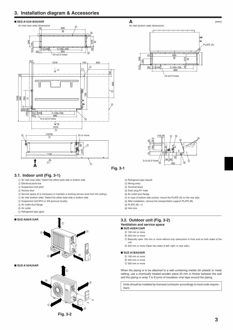
3.1. Indoor unit (Fig. 3-1)1 Air inlet (rear side) *Select the either back side or bottom side
2 Electrical parts box
3 Suspension bolt pitch
5 Access door
6 Service space (It is necessary to maintain a working service area from the ceiling.)
7 Air inlet (bottom side) *Select the either back side or bottom side
8 Suspension bolt M10 or 3/8 (procure locally)
9 Air outlet duct flange
0 Air outlet
A Refrigerant pipe (gas)
(mm)
Fig. 3-1
SUZ-A09/A12AR
A
C
A
C
B
3.2. Outdoor unit (Fig. 3-2)Ventilation and service space SUZ-A09/A12AR
A 100 mm or more
B 350 mm or more
C Basically open 100 mm or more without only obstruction in front and on both sides of theunit.
D 200 mm or more (Open two sides of left, right, or rear side.)
SUZ-A18/A24ARA 100 mm or more
B 350 mm or more
C 500 mm or more
When the piping is to be attached to a wall containing metals (tin plated) or metalnetting, use a chemically treated wooden piece 20 mm or thicker between the walland the piping or wrap 7 to 8 turns of insulation vinyl tape around the piping.
Units should be installed by licensed contractor accordingly to local code require-ment.
SUZ-A18/A24AR
A
D
C
A
B
42 930
7×100=7001002912
.512
0240
77.5955
215
25
H
J
I
G
J
50271016
7×100=700880
10040
(10)
506035
038
680
5010
00
50
1070
150
77
450
150
600
700
2
1
3
0
3
5
6
9
83
2
57
A
(1070)
270
30
1100
2575
32.5
(10) 50
94 60
350
100
108
25
20
170
A
F
B
CD
2E
240
12.5
120
2521
5
39 77.5 100 7×100=700955
93051J J
SEZ-A12/A18/A24AR
B Refrigerant pipe (liquid)
C Wiring entry
D Terminal block
E Drain plug R1 male
F Air outlet duct flange
G In case of bottom side suction, mount the PLATE (A) on the rear side.
H After installation, remove the transportation support PLATE (B).
I PLATE (B) × 2
J Inlet size
AAir inlet (bottom side) dimensions
PLATE (A)
24-ø2.9 holes
2×2-ø2.9 holes
20 or more
24-ø2.9 holes
Air inlet (rear side) dimensions
9×2-ø2.9 holes
Fig. 3-2
4
A B
1
2
3
3. Installation diagram & Accessories
Fig. 3-3
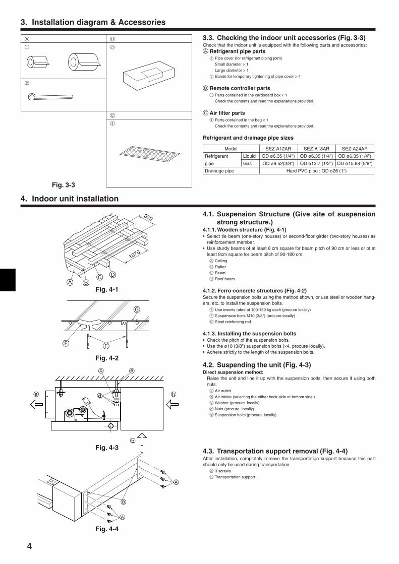
3.3. Checking the indoor unit accessories (Fig. 3-3)Check that the indoor unit is equipped with the following parts and accessories:A Refrigerant pipe parts
1 Pipe cover (for refrigerant piping joint)
Small diameter × 1
Large diameter × 1
2 Bands for temporary tightening of pipe cover × 4
B Remote controller parts3 Parts contained in the cardboard box × 1
Check the contents and read the explanations provided.
C Air filter parts4 Parts contained in the bag × 1
Check the contents and read the explanations provided.
Refrigerant and drainage pipe sizes
Model SEZ-A12AR SEZ-A18AR SEZ-A24AR
Refrigerant Liquid OD ø6.35 (1/4") OD ø6.35 (1/4") OD ø6.35 (1/4")
pipe Gas OD ø9.52(3/8") OD ø12.7 (1/2") OD ø15.88 (5/8")
Drainage pipe Hard PVC pipe : OD ø26 (1")
4. Indoor unit installation
4.1. Suspension Structure (Give site of suspensionstrong structure.)
4.1.1. Wooden structure (Fig. 4-1)• Select tie beam (one-story houses) or second-floor girder (two-story houses) as
reinforcement member.• Use sturdy beams of at least 6 cm square for beam pitch of 90 cm or less or of at
least 9cm square for beam pitch of 90-180 cm.A Ceiling
B Rafter
C Beam
D Roof beam
4.1.2. Ferro-concrete structures (Fig. 4-2)Secure the suspension bolts using the method shown, or use steel or wooden hang-ers, etc. to install the suspension bolts.
E Use inserts rated at 100-150 kg each (procure locally)
F Suspension bolts M10 (3/8") (procure locally)
G Steel reinforcing rod
4.1.3. Installing the suspension bolts• Check the pitch of the suspension bolts.• Use the ø10 (3/8") suspension bolts (×4, procure locally).• Adhere strictly to the length of the suspension bolts.
4.2. Suspending the unit (Fig. 4-3)Direct suspension method:
Raise the unit and line it up with the suspension bolts, then secure it using bothnuts.
a Air outlet
b Air intake (selecting the either back side or bottom side.)
c Washer (procure locally)
d Nuts (procure locally)
e Suspension bolts (procure locally)
G
E F
a b
b
c e
d
B
A
A
A BC D
350
1070
Fig. 4-1
Fig. 4-3
Fig. 4-4
Fig. 4-2
4.3. Transportation support removal (Fig. 4-4)After installation, completely remove the transportation support because this partshould only be used during transportation.
A 3 screws
B Transportation support
C
4
5
5. Refrigerant piping work
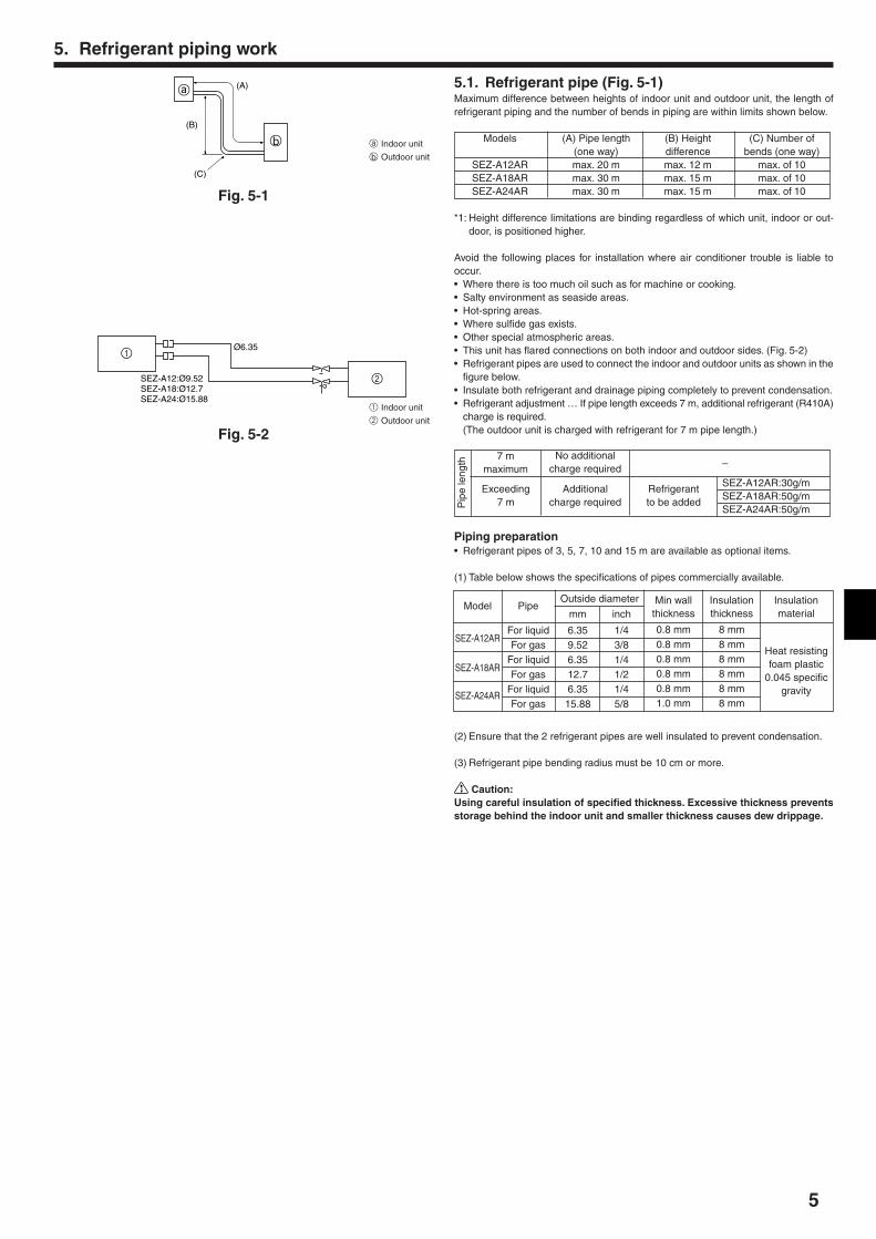
5.1. Refrigerant pipe (Fig. 5-1)Maximum difference between heights of indoor unit and outdoor unit, the length ofrefrigerant piping and the number of bends in piping are within limits shown below.
Models (A) Pipe length (B) Height (C) Number of(one way) difference bends (one way)
SEZ-A12AR max. 20 m max. 12 m max. of 10SEZ-A18AR max. 30 m max. 15 m max. of 10SEZ-A24AR max. 30 m max. 15 m max. of 10
*1: Height difference limitations are binding regardless of which unit, indoor or out-door, is positioned higher.
Avoid the following places for installation where air conditioner trouble is liable tooccur.• Where there is too much oil such as for machine or cooking.• Salty environment as seaside areas.• Hot-spring areas.• Where sulfide gas exists.• Other special atmospheric areas.• This unit has flared connections on both indoor and outdoor sides. (Fig. 5-2)• Refrigerant pipes are used to connect the indoor and outdoor units as shown in the
figure below.• Insulate both refrigerant and drainage piping completely to prevent condensation.• Refrigerant adjustment … If pipe length exceeds 7 m, additional refrigerant (R410A)
charge is required.(The outdoor unit is charged with refrigerant for 7 m pipe length.)
–
SEZ-A12AR:30g/mSEZ-A18AR:50g/mSEZ-A24AR:50g/m
Piping preparation• Refrigerant pipes of 3, 5, 7, 10 and 15 m are available as optional items.
(1) Table below shows the specifications of pipes commercially available.
(2) Ensure that the 2 refrigerant pipes are well insulated to prevent condensation.
(3) Refrigerant pipe bending radius must be 10 cm or more.
Caution:Using careful insulation of specified thickness. Excessive thickness preventsstorage behind the indoor unit and smaller thickness causes dew drippage.
Ø6.35
SEZ-A12:Ø9.52SEZ-A18:Ø12.7SEZ-A24:Ø15.88
1
2
b
(C)
(B)
(A)a
Fig. 5-1
Fig. 5-2
Pip
e le
ngth
7 mmaximum
No additionalcharge required
Refrigerantto be added
Additionalcharge required
Exceeding7 m
a Indoor unit
b Outdoor unit
1 Indoor unit
2 Outdoor unit
Pipe
For liquidFor gas
For liquidFor gas
For liquidFor gas
Outside diameter
mm inch
6.35 1/49.52 3/86.35 1/412.7 1/26.35 1/415.88 5/8
Model
SEZ-A12AR
SEZ-A18AR
SEZ-A24AR
Insulationmaterial
Heat resistingfoam plastic
0.045 specificgravity
Insulationthickness
8 mm8 mm8 mm8 mm8 mm8 mm
Min wallthickness
0.8 mm0.8 mm0.8 mm0.8 mm0.8 mm1.0 mm
6
ad
cb
e f90°
d
c
ba
5. Refrigerant piping work
b
a
a
b
e
bc
dc
A
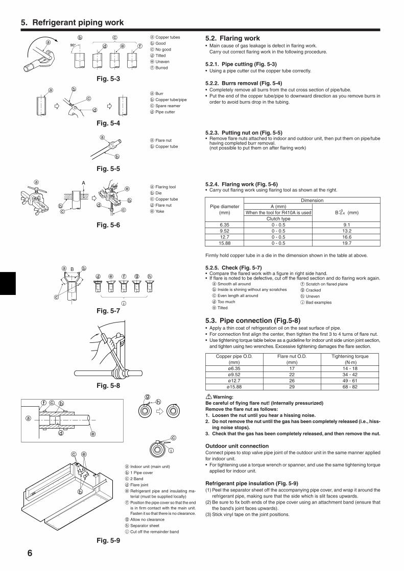
5.2. Flaring work• Main cause of gas leakage is defect in flaring work.
Carry out correct flaring work in the following procedure.
5.2.1. Pipe cutting (Fig. 5-3)• Using a pipe cutter cut the copper tube correctly.
5.2.2. Burrs removal (Fig. 5-4)• Completely remove all burrs from the cut cross section of pipe/tube.• Put the end of the copper tube/pipe to downward direction as you remove burrs in
order to avoid burrs drop in the tubing.
5.2.3. Putting nut on (Fig. 5-5)• Remove flare nuts attached to indoor and outdoor unit, then put them on pipe/tube
having completed burr removal.(not possible to put them on after flaring work)
5.2.4. Flaring work (Fig. 5-6)• Carry out flaring work using flaring tool as shown at the right.
DimensionPipe diameter A (mm)
(mm) When the tool for R410A is used B (mm)Clutch type
6.35 0 - 0.5 9.19.52 0 - 0.5 13.212.7 0 - 0.5 16.615.88 0 - 0.5 19.7
Firmly hold copper tube in a die in the dimension shown in the table at above.
5.2.5. Check (Fig. 5-7)• Compare the flared work with a figure in right side hand.• If flare is noted to be defective, cut off the flared section and do flaring work again.
5.3. Pipe connection (Fig.5-8)• Apply a thin coat of refrigeration oil on the seat surface of pipe.• For connection first align the center, then tighten the first 3 to 4 turns of flare nut.• Use tightening torque table below as a guideline for indoor unit side union joint section,
and tighten using two wrenches. Excessive tightening damages the flare section.
Copper pipe O.D. Flare nut O.D. Tightening torque(mm) (mm) (N·m)ø6.35 17 14 - 18ø9.52 22 34 - 42ø12.7 26 49 - 61ø15.88 29 68 - 82
Warning:Be careful of flying flare nut! (Internally pressurized)Remove the flare nut as follows:1. Loosen the nut until you hear a hissing noise.2. Do not remove the nut until the gas has been completely released (i.e., hiss-
ing noise stops).3. Check that the gas has been completely released, and then remove the nut.
Outdoor unit connectionConnect pipes to stop valve pipe joint of the outdoor unit in the same manner appliedfor indoor unit.• For tightening use a torque wrench or spanner, and use the same tightening torque
applied for indoor unit.
Refrigerant pipe insulation (Fig. 5-9)(1) Peel the separator sheet off the accompanying pipe cover, and wrap it around the
refrigerant pipe, making sure that the side which is slit faces upwards.(2) Be sure to fix both ends of the pipe cover using an attachment band (ensure that
the band’s joint faces upwards).(3) Stick vinyl tape on the joint positions.
a Copper tubes
b Good
c No good
d Tilted
e Uneven
f Burred
Fig. 5-3
Fig. 5-4
a Burr
b Copper tube/pipe
c Spare reamer
d Pipe cutter
Fig. 5-5
Fig. 5-6
Fig. 5-7
Fig. 5-8
Fig. 5-9
a Flare nut
b Copper tube
a Flaring tool
b Die
c Copper tube
d Flare nut
e Yoke
a
f c b
d e
b
c e
gh
c
i
a Indoor unit (main unit)
b 1 Pipe cover
c 2 Band
d Flare joint
e Refrigerant pipe and insulating ma-terial (must be supplied locally)
f Position the pipe cover so that the endis in firm contact with the main unit.Fasten it so that there is no clearance.
g Allow no clearance
h Separator sheet
i Cut off the remainder band
a Smooth all aroundb Inside is shining without any scratches
c Even length all around
d Too much
e Tilted
f Scratch on flared plane
g Cracked
h Uneven
i Bad examplesc
ba
d e f g h
i
B
+0-0.4
7
5. Refrigerant piping work
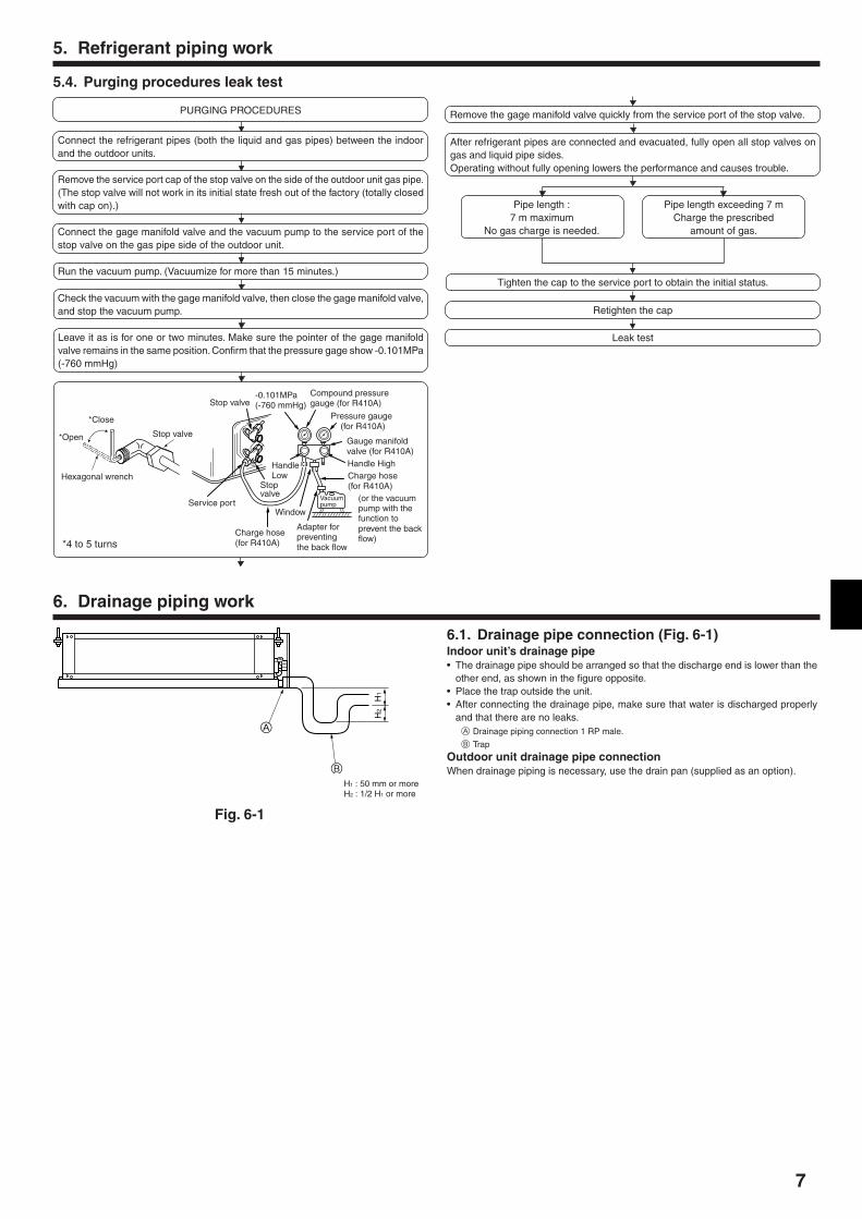
5.4. Purging procedures leak test
PURGING PROCEDURES
Connect the refrigerant pipes (both the liquid and gas pipes) between the indoorand the outdoor units.
Remove the service port cap of the stop valve on the side of the outdoor unit gas pipe.(The stop valve will not work in its initial state fresh out of the factory (totally closedwith cap on).)
Connect the gage manifold valve and the vacuum pump to the service port of thestop valve on the gas pipe side of the outdoor unit.
Run the vacuum pump. (Vacuumize for more than 15 minutes.)
Check the vacuum with the gage manifold valve, then close the gage manifold valve,and stop the vacuum pump.
Leave it as is for one or two minutes. Make sure the pointer of the gage manifoldvalve remains in the same position. Confirm that the pressure gage show -0.101MPa(-760 mmHg)
Pipe length :7 m maximum
No gas charge is needed.
Pipe length exceeding 7 mCharge the prescribed
amount of gas.
Remove the gage manifold valve quickly from the service port of the stop valve.
After refrigerant pipes are connected and evacuated, fully open all stop valves ongas and liquid pipe sides.Operating without fully opening lowers the performance and causes trouble.
Tighten the cap to the service port to obtain the initial status.
Retighten the cap
Leak test
*Close
*Open
Hexagonal wrench
Stop valve
*4 to 5 turns
Stop valve
(or the vacuumpump with thefunction toprevent the backflow)
Gauge manifoldvalve (for R410A)
Pressure gauge (for R410A)
Compound pressuregauge (for R410A)
-0.101MPa(-760 mmHg)
HandleLow
Handle High
Window
Charge hose(for R410A)
Vacuumpump
Adapter forpreventingthe back flow
Charge hose(for R410A)
Service port
Stopvalve
6. Drainage piping work
Fig. 6-1
6.1. Drainage pipe connection (Fig. 6-1)Indoor unit’s drainage pipe• The drainage pipe should be arranged so that the discharge end is lower than the
other end, as shown in the figure opposite.• Place the trap outside the unit.• After connecting the drainage pipe, make sure that water is discharged properly
and that there are no leaks.A Drainage piping connection 1 RP male.
B Trap
Outdoor unit drainage pipe connectionWhen drainage piping is necessary, use the drain pan (supplied as an option).
A
B
H1
H2
H1 : 50 mm or moreH2 : 1/2 H1 or more
8
7. Electrical work
N
AB
H
C
FD
E
A G
N2 3
N2 3
NL
L
1 2
N
B
C
F
E
N2 3 1 2 NL
L
A
H
A
D
CE
A
GN3
N F
NL
L
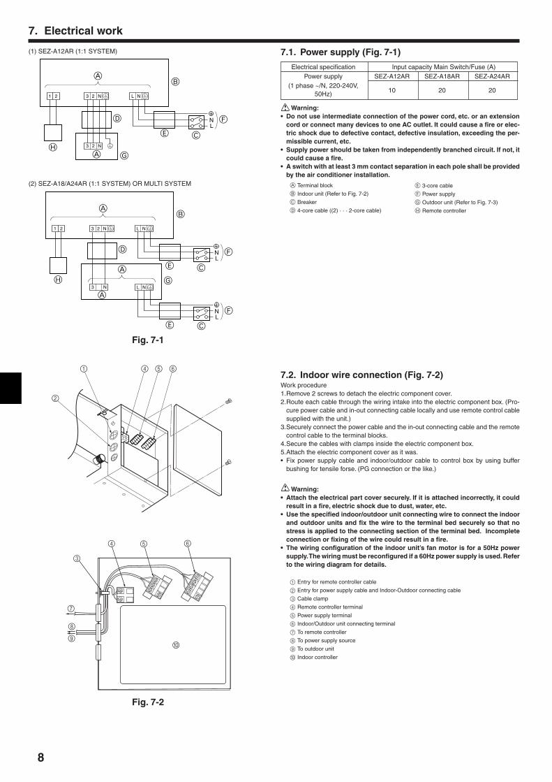
(1) SEZ-A12AR (1:1 SYSTEM) 7.1. Power supply (Fig. 7-1)
Electrical specification Input capacity Main Switch/Fuse (A)Power supply SEZ-A12AR SEZ-A18AR SEZ-A24AR
(1 phase ~/N, 220-240V,50Hz) 10 20 20
Warning:• Do not use intermediate connection of the power cord, etc. or an extension
cord or connect many devices to one AC outlet. It could cause a fire or elec-tric shock due to defective contact, defective insulation, exceeding the per-missible current, etc.
• Supply power should be taken from independently branched circuit. If not, itcould cause a fire.
• A switch with at least 3 mm contact separation in each pole shall be providedby the air conditioner installation.
A Terminal block
B Indoor unit (Refer to Fig. 7-2)
C Breaker
D 4-core cable ((2) · · · 2-core cable)
E 3-core cable
F Power supply
G Outdoor unit (Refer to Fig. 7-3)
H Remote controller
(2) SEZ-A18/A24AR (1:1 SYSTEM) OR MULTI SYSTEM
Fig. 7-1
Fig. 7-2
7.2. Indoor wire connection (Fig. 7-2)Work procedure1.Remove 2 screws to detach the electric component cover.2.Route each cable through the wiring intake into the electric component box. (Pro-
cure power cable and in-out connecting cable locally and use remote control cablesupplied with the unit.)
3.Securely connect the power cable and the in-out connecting cable and the remotecontrol cable to the terminal blocks.
4.Secure the cables with clamps inside the electric component box.5.Attach the electric component cover as it was.• Fix power supply cable and indoor/outdoor cable to control box by using buffer
bushing for tensile forse. (PG connection or the like.)
Warning:• Attach the electrical part cover securely. If it is attached incorrectly, it could
result in a fire, electric shock due to dust, water, etc.• Use the specified indoor/outdoor unit connecting wire to connect the indoor
and outdoor units and fix the wire to the terminal bed securely so that nostress is applied to the connecting section of the terminal bed. Incompleteconnection or fixing of the wire could result in a fire.
• The wiring configuration of the indoor unit’s fan motor is for a 50Hz powersupply. The wiring must be reconfigured if a 60Hz power supply is used. Referto the wiring diagram for details.
1 Entry for remote controller cable
2 Entry for power supply cable and Indoor-Outdoor connecting cable
3 Cable clamp
4 Remote controller terminal
5 Power supply terminal
6 Indoor/Outdoor unit connecting terminal
7 To remote controller
8 To power supply source
9 To outdoor unit
0 Indoor controller
2
1 4 5 6
3
4 5 6
0
7
8
9

9
7. Electrical work
Fig. 7-4
L N
N2 3
N2 3
1
2
5
1 2
7
6
3
4
65 mm
15 mm
1
2
Fig. 7-3
• Perform wiring as shown in the diagram to the lower left. (Procure the cable lo-cally). (Fig. 7-3)Make sure to use cables of the correct polarity only.
1 Connecting cable 2 Power supply cable
4 core VVF cable 3 core with ground IEC cord
• SEZ-A12:1.0 mm2 or more • SEZ-A12:1.0 mm2 or more
• SEZ-A18, A24:1.5 mm2 or more • SEZ-A18, A24:1.5 mm2 or more
Colors Colors
N : Blue N : Blue
2 : Brown L : Brown
3 : Red : Green/Yellow
: Green/Yellow
3 Indoor
4 Outdoor
5 Always install an earth longer than other cables
6 Remote controller cable
Wire No × size (mm2) : Cable 2C × 0.69
This wire accessory of remote controller
(wire length : 10m, non-polar)
7 Remote controller
• Connect the terminal blocks as shown in the diagram below. (Fig. 7-4)1 Loosen terminal screw
2 Terminal bed(1) Use care not to make mis-wiring.(2) Firmly tighten the terminal screws to prevent then from loosening.(3) After tightening, pull the wires lightly to confirm that they do not move.
7.3. Remote controller7.3.1. For wired remote controller1) Installing procedures(1) Select an installing position for the remote controller. (Fig. 7-5)The temperature sensors are located on both remote controller and indoor unit.s Procure the following parts locally:
Two piece switch boxThin copper conduit tubeLock nuts and bushingsA Remote controller profile
B Required clearances surrounding the remote controller
C Installation pitch(2) Seal the service entrance for the remote controller cord with putty to prevent
possible invasion of dew drops, water, cockroaches or worms. (Fig. 7-6)A For installation in the switch box:B For direct installation on the wall select one of the following:• Prepare a hole through the wall to pass the remote controller cord (in order to run
the remote controller cord from the back), then seal the hole with putty.• Run the remote controller cord through the cut-out upper case, then seal the cut-
out notch with putty similarly as above.B-1. To lead the remote controller cord from the back of the controller:B-2. To run the remote controller cord through the upper portion:(3) For direct installation on the wall
C Wall
D Conduit
E Lock nut
F Bushing
G Switch box
H Remote controller cord
I Seal with putty
J Wood screw2) Connecting procedures (Fig. 7-7)1 Connect the remote controller cord to the terminal block.
A To the terminal block on the indoor unit
B TB6 (No polarity)2 Set the dip switch No.1 shown below when using two remote controller’s for the
same group.C Dip switches
Setting the dip switches
The dip switches are at the bottom of the remote controller. Remote controller Main/Sub and other function settings are performed using these switches. Ordinarily, onlychange the Main/Sub setting of SW No.1. (The factory settings are all “ON”.)
30
46
30
3012
0
83.5
A
B
C
F
A
H
C D
E
GI
I
I
H
B
J
H
B-1. B-2.
Fig. 7-6
A
AB TB6
B
1 2 3 4
ON
1 2 3 4
ON
C
<SW No. 1>SW contents Main Remote controller Main/Sub setting
ON/OFFComment Set one of the two remote controllers at one group to “Main”
Main/Sub
<SW No. 2>SW contents Main When remote controller power turned on
ON/OFF
CommentWhen you want to return to the timer mode when the power is restoredafter a power failure when a Program timer is connected, select “Timermode”.
Normally on/Timer mode on
<SW No. 3>SW contents Main Cooling/heating display in AUTO mode
ON/OFF
CommentWhen you do not want to display “Cooling” and “Heating” in the Automode, set to “No”.
Yes/No
<SW No. 4>SW contents Main Intake temperature display
ON/OFF
Comment When you do not want to display the intake temperature, set to “No”.
Yes/No
Fig. 7-5
Fig. 7-7
L N
N3
N2 3
1
2
5
L N
2
5
1 2
7
6
3
4
(1) SEZ-A12AR (1:1 SYSTEM) (2) SEZ-A18/24AR (1:1 SYSTEM) ORMULTI SYSTEM
10
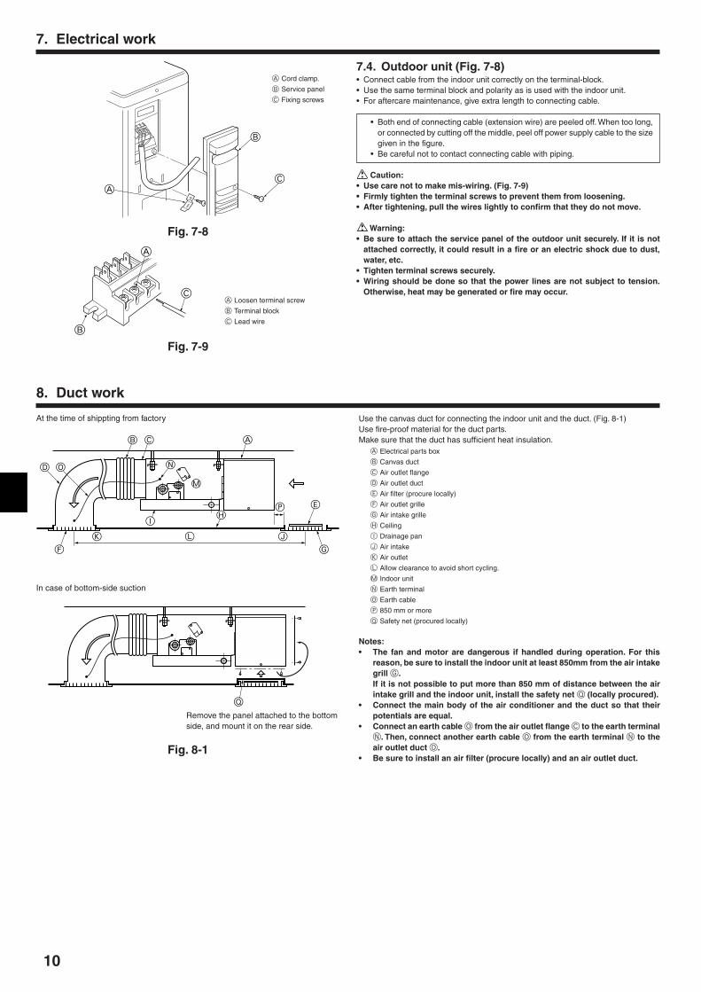
7.4. Outdoor unit (Fig. 7-8)• Connect cable from the indoor unit correctly on the terminal-block.• Use the same terminal block and polarity as is used with the indoor unit.• For aftercare maintenance, give extra length to connecting cable.
• Both end of connecting cable (extension wire) are peeled off. When too long,or connected by cutting off the middle, peel off power supply cable to the sizegiven in the figure.
• Be careful not to contact connecting cable with piping.
Caution:• Use care not to make mis-wiring. (Fig. 7-9)• Firmly tighten the terminal screws to prevent them from loosening.• After tightening, pull the wires lightly to confirm that they do not move.
Warning:• Be sure to attach the service panel of the outdoor unit securely. If it is not
attached correctly, it could result in a fire or an electric shock due to dust,water, etc.
• Tighten terminal screws securely.• Wiring should be done so that the power lines are not subject to tension.
Otherwise, heat may be generated or fire may occur.A Loosen terminal screw
B Terminal block
C Lead wire
A
B
C
Fig. 7-8
Fig. 7-9B
C
A
A Cord clamp.
B Service panel
C Fixing screws
7. Electrical work
Use the canvas duct for connecting the indoor unit and the duct. (Fig. 8-1)Use fire-proof material for the duct parts.Make sure that the duct has sufficient heat insulation.
A Electrical parts box
B Canvas duct
C Air outlet flange
D Air outlet duct
E Air filter (procure locally)
F Air outlet grille
G Air intake grille
H Ceiling
I Drainage pan
J Air intake
K Air outlet
L Allow clearance to avoid short cycling.
M Indoor unit
N Earth terminal
O Earth cable
P 850 mm or more
Q Safety net (procured locally)
Notes:• The fan and motor are dangerous if handled during operation. For this
reason, be sure to install the indoor unit at least 850mm from the air intakegrill G.If it is not possible to put more than 850 mm of distance between the airintake grill and the indoor unit, install the safety net Q (locally procured).
• Connect the main body of the air conditioner and the duct so that theirpotentials are equal.
• Connect an earth cable O from the air outlet flange C to the earth terminalN. Then, connect another earth cable O from the earth terminal N to theair outlet duct D.
• Be sure to install an air filter (procure locally) and an air outlet duct.
8. Duct work
At the time of shippting from factory
In case of bottom-side suction
Q
B C
N
A
M
EPH
G
L JK
F
I
D O
Remove the panel attached to the bottomside, and mount it on the rear side.
Fig. 8-1
11
9. Air filter installation
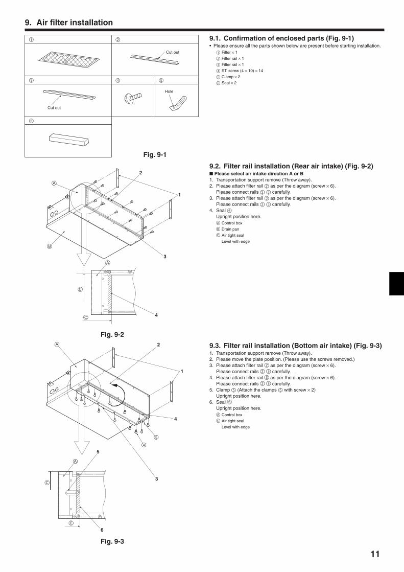
9.1. Confirmation of enclosed parts (Fig. 9-1)• Please ensure all the parts shown below are present before starting installation.
1 Filter × 1
2 Filter rail × 1
3 Filter rail × 1
4 ST. screw (4 × 10) × 14
5 Clamp × 2
6 Seal × 2
1 2
3
Fig. 9-1
6
Cut out
Cut out
Hole
4 5
A
A
B
C
C
2
1
3
4
Fig. 9-2
9.2. Filter rail installation (Rear air intake) (Fig. 9-2) Please select air intake direction A or B1. Transportation support remove (Throw away).2. Please attach filter rail 2 as per the diagram (screw × 6).
Please connect rails 2 3 carefully.3. Please attach filter rail 3 as per the diagram (screw × 6).
Please connect rails 2 3 carefully.4. Seal 6
Upright position here.A Control box
B Drain pan
C Air tight seal
Level with edge
A
A
5
4
C
C
4
3
5
6
2
1
Fig. 9-3
9.3. Filter rail installation (Bottom air intake) (Fig. 9-3)1. Transportation support remove (Throw away).2. Please move the plate position. (Please use the screws removed.)3. Please attach filter rail 2 as per the diagram (screw × 6).
Please connect rails 2 3 carefully.4. Please attach filter rail 3 as per the diagram (screw × 6).
Please connect rails 2 3 carefully.5. Clamp 5 (Attach the clamps 5 with screw × 2)
Upright position here.6. Seal 6
Upright position here.A Control box
C Air tight seal
Level with edge
12
9. Air filter installation
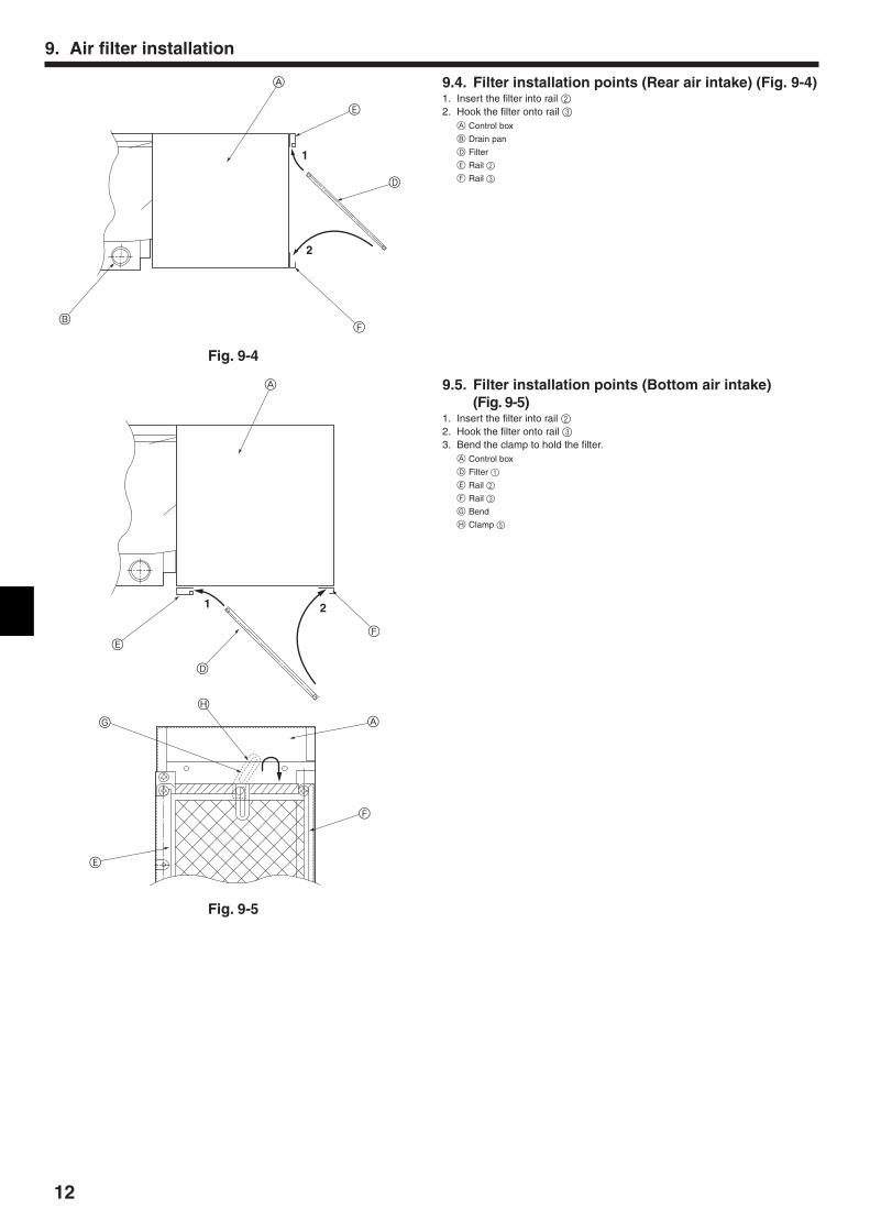
9.4. Filter installation points (Rear air intake) (Fig. 9-4)1. Insert the filter into rail 22. Hook the filter onto rail 3
A Control box
B Drain pan
D Filter
E Rail 2
F Rail 3
Fig. 9-4
1
2
B
A
E
D
F
Fig. 9-5
21
A
E
D
F
A
F
H
G
E
9.5. Filter installation points (Bottom air intake)(Fig. 9-5)
1. Insert the filter into rail 22. Hook the filter onto rail 33. Bend the clamp to hold the filter.
A Control box
D Filter 1
E Rail 2
F Rail 3
G Bend
H Clamp 5
13
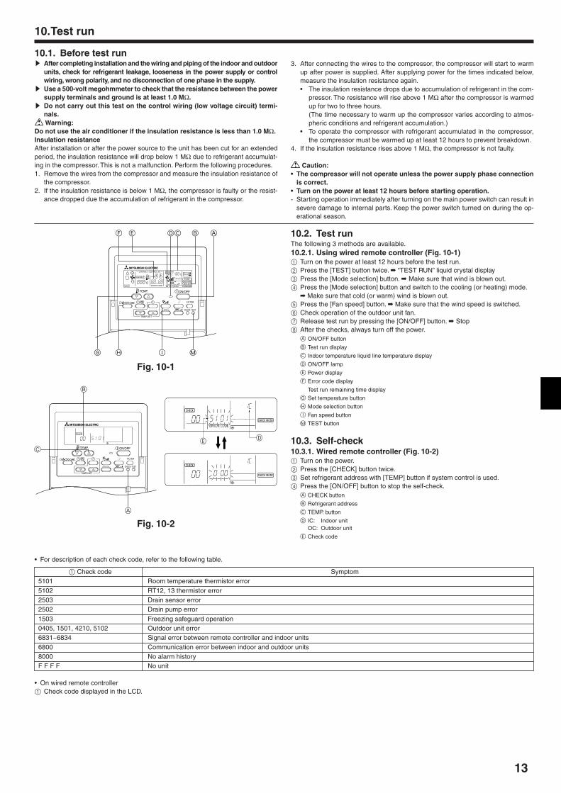
10.1. Before test runs After completing installation and the wiring and piping of the indoor and outdoor
units, check for refrigerant leakage, looseness in the power supply or controlwiring, wrong polarity, and no disconnection of one phase in the supply.
s Use a 500-volt megohmmeter to check that the resistance between the powersupply terminals and ground is at least 1.0 MΩ.
s Do not carry out this test on the control wiring (low voltage circuit) termi-nals. Warning:
Do not use the air conditioner if the insulation resistance is less than 1.0 MΩ.Insulation resistanceAfter installation or after the power source to the unit has been cut for an extendedperiod, the insulation resistance will drop below 1 MΩ due to refrigerant accumulat-ing in the compressor. This is not a malfunction. Perform the following procedures.1. Remove the wires from the compressor and measure the insulation resistance of
the compressor.2. If the insulation resistance is below 1 MΩ, the compressor is faulty or the resist-
ance dropped due the accumulation of refrigerant in the compressor.
3. After connecting the wires to the compressor, the compressor will start to warmup after power is supplied. After supplying power for the times indicated below,measure the insulation resistance again.• The insulation resistance drops due to accumulation of refrigerant in the com-
pressor. The resistance will rise above 1 MΩ after the compressor is warmedup for two to three hours.(The time necessary to warm up the compressor varies according to atmos-pheric conditions and refrigerant accumulation.)
• To operate the compressor with refrigerant accumulated in the compressor,the compressor must be warmed up at least 12 hours to prevent breakdown.
4. If the insulation resistance rises above 1 MΩ, the compressor is not faulty.
Caution:• The compressor will not operate unless the power supply phase connection
is correct.• Turn on the power at least 12 hours before starting operation.- Starting operation immediately after turning on the main power switch can result in
severe damage to internal parts. Keep the power switch turned on during the op-erational season.
10.Test run
10.2. Test runThe following 3 methods are available.10.2.1. Using wired remote controller (Fig. 10-1)1 Turn on the power at least 12 hours before the test run.2 Press the [TEST] button twice. “TEST RUN” liquid crystal display3 Press the [Mode selection] button. Make sure that wind is blown out.4 Press the [Mode selection] button and switch to the cooling (or heating) mode.
Make sure that cold (or warm) wind is blown out.5 Press the [Fan speed] button. Make sure that the wind speed is switched.6 Check operation of the outdoor unit fan.7 Release test run by pressing the [ON/OFF] button. Stop8 After the checks, always turn off the power.
A ON/OFF button
B Test run display
C Indoor temperature liquid line temperature display
D ON/OFF lamp
E Power display
F Error code display
Test run remaining time display
G Set temperature button
H Mode selection button
I Fan speed button
M TEST button
10.3. Self-check10.3.1. Wired remote controller (Fig. 10-2)1 Turn on the power.2 Press the [CHECK] button twice.3 Set refrigerant address with [TEMP] button if system control is used.4 Press the [ON/OFF] button to stop the self-check.
A CHECK button
B Refrigerant address
C TEMP. button
D IC: Indoor unitOC: Outdoor unit
E Check code
ON/OFF
CENTRALLY CONTROLLED
ERROR CODE
CLOCK
ON OFF
˚C
CHECK
CHECK MODEFILTER
TEST RUNFUNCTION
˚C1Hr.
NOT AVAILABLESTAND BY DEFROST
FILTER
CHECK TEST
TEMP.
TIMER SET
DEF
H I MG
C B A
Fig. 10-1
ON/OFF
CHECK
FILTER
CHECK TEST
TEMP.
TIMER SET
B
C
A
STAND BY DEFROST
INDOOR UNITADDRESS NO
ERROR CODEOA UNIT ADDRESS NO
CENTRALLY CONTROLLED
CLOCK
ON OFF ˚C
1Hr.
NOT AVAILABLE
˚C CHECK MODE
FILTERCHECK
FUNCTION
ERROR CODEOA UNIT ADDRESS NO
STAND BY DEFROST
INDOOR UNITADDRESS NO
CENTRALLY CONTROLLED
CLOCK
ON OFF ˚C
1Hr.
NOT AVAILABLE
˚C CHECK MODE
FILTERCHECK
FUNCTION
a) DE
• For description of each check code, refer to the following table.
1 Check code Symptom5101 Room temperature thermistor error5102 RT12, 13 thermistor error2503 Drain sensor error2502 Drain pump error1503 Freezing safeguard operation0405, 1501, 4210, 5102 Outdoor unit error6831~6834 Signal error between remote controller and indoor units6800 Communication error between indoor and outdoor units8000 No alarm historyF F F F No unit
• On wired remote controller1 Check code displayed in the LCD.
Fig. 10-2

14
10.4. AUTO RESTART FUNCTIONThis model is equipped with the AUTO RESTART FUNCTION.When the indoor unit is controlled with the remote controller, the operation mode,set temperature, and the fan speed are memorized by the indoor controller board.The auto restart function sets to work the moment the power has restored afterpower failure, then, the unit will restart automatically.Notes:• The operation settings are memorized when 10 seconds have passed after
the remote controller was operated.
10.Test run
• If the main power is turned off or a power failure occurs while AUTO START/STOP timer is active, the timer setting is cancelled. As this model is equippedwith the auto restart function, the air conditioner should start operating atthe same time that a power has restored.
• If the unit has been off with the remote controller before power failure, theauto restart function does not work as the power button of the remote con-troller is off.
• To prevent breaker off due to the rush of starting current, systematize otherhome appliance not to turn on at the same time.
11.Maintenance
11.1. Gas charge (Fig. 11-1)1. Connect gas cylinder to the service port of stop valve (3-way).2. Execute air purge of the pipe (or hose) coming from refrigerant gas cylinder.3. Replenish specified amount of refrigerant, while running the air conditioner
for cooling.
Note:In case of adding refrigerant, comply with the quantity specified for the refrigeratingcycle.
Caution:• Do not discharge the refrigerant into the atmosphere.
Take care not to discharge refrigerant into the atmosphere during installa-tion, reinstallation, or repairs to the refrigerant circuit.
• For additional charging, charge the refrigerant from liquid phase of the gascylinder.If the refrigerant is charged from the gas phase, composition change mayoccur in the refrigerant inside the cylinder and the outdoor unit. In this case,ability of the refrigerating cycle decreases or normal operation can be impos-sible. However, charging the liquid refrigerant all at once may cause the com-pressor to be locked. Thus, charge the refrigerant slowly.
To maintain the high pressure of the gas cylinder, warm the gas cylinder with warmwater (under 40°C) during cold season. But never use naked fire or steam.
B
A
G
H
K
L
M
IJ
C
D
E
F
A Indoor unit
B Union
C Liquid pipe
D Gas pipe
E Stop valve
F Outdoor unit
G Refrigerant gas cylinder operating valve
H Refrigerant gas cylinder for R410A withsiphon
I Refrigerant (liquid)
J Electronic scale for refrigerant charging
K Charge hose (for R410A)
L Gauge manifold valve (for R410A)
M Service port
Fig. 11-1
10.5. Indoor temperature position change function(Fig. 10-3)
This model is equipped with the indoor temperature position change function. Detec-tion of room temperature can be changed into remote controller’s internal sensor.1 Power supply is turn off.2 Cut the JP14 jumper wire of the indoor controller board with a pair of nippers.
A Indoor controller board
RC00J590B 52C
C412
C1
FAN
2FA
N1
CN
PC
NC
CN
D
JP14
A
Fig. 10-3
15
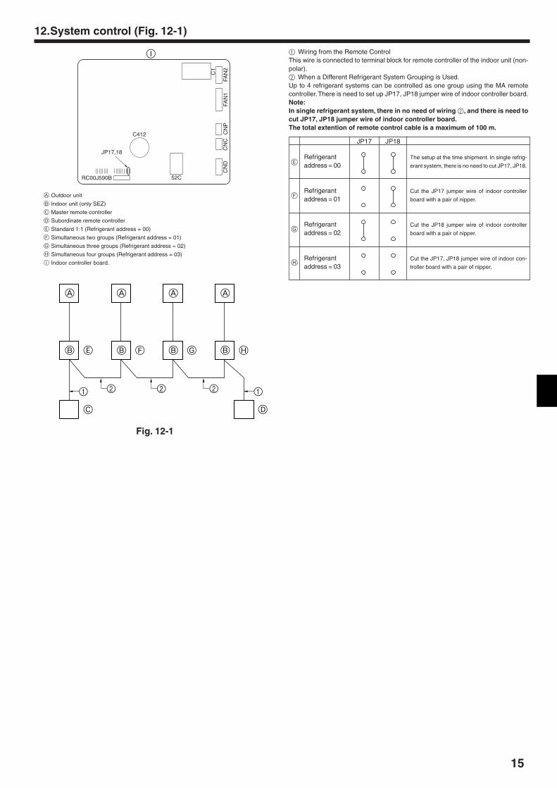
1 Wiring from the Remote ControlThis wire is connected to terminal block for remote controller of the indoor unit (non-polar).2 When a Different Refrigerant System Grouping is Used.Up to 4 refrigerant systems can be controlled as one group using the MA remotecontroller. There is need to set up JP17, JP18 jumper wire of indoor controller board.Note:In single refrigerant system, there in no need of wiring 2, and there is need tocut JP17, JP18 jumper wire of indoor controller board.The total extention of remote control cable is a maximum of 100 m.
12.System control (Fig. 12-1)
A Outdoor unit
B Indoor unit (only SEZ)
C Master remote controller
D Subordinate remote controller
E Standard 1:1 (Refrigerant address = 00)
F Simultaneous two groups (Refrigerant address = 01)
G Simultaneous three groups (Refrigerant address = 02)
H Simultaneous four groups (Refrigerant address = 03)
I Indoor controller board.
Refrigerantaddress = 00
Refrigerantaddress = 01
Refrigerantaddress = 02
Refrigerantaddress = 03
The setup at the time shipment. In single refrig-
erant system, there is no need to cut JP17, JP18.
Cut the JP17 jumper wire of indoor controller
board with a pair of nipper.
Cut the JP18 jumper wire of indoor controller
board with a pair of nipper.
Cut the JP17, JP18 jumper wire of indoor con-
troller board with a pair of nipper.
JP17 JP18
A
B E
C
1
A
B F
A
B G
A
B H
D
12 2 2
RC00J590B 52C
C412
C1
FAN
2FA
N1
CN
PC
NC
CN
D
JP17,18
I
Fig. 12-1
E
F
G
H
Please be sure to put the contact address/telephone number onthis manual before handing it to the customer.
• Low Voltage Directive 73/23/ EEC• Electromagnetic Compatibility Directive 89/
336/ EEC
This product is designed and intended for use in the residential,commercial and light-industrial environment.
HEAD OFFICE: MITSUBISHI DENKI BLDG., 2-2-3, MARUNOUCHI, CHIYODA-KU, TOKYO 100-8310, JAPAN
BG79S993H01
The product at hand isbased on the followingEU regulations:
Printed in Thailand