sewerage system – south jerrabomberra · 2018-04-12 · 3 superimposed loads d12.06 a hb 11/04 4...
TRANSCRIPT
SEWERAGE SYSTEM – SOUTH JERRABOMBERRA
AUS-SPEC-1\NSW-D12-SOUTH JERRABOMBERRA-VERSION 2 QUEANBEYAN PALERANG REGIONAL COUNCIL
QUEANBEYAN PALERANG REGIONAL COUNCIL
DEVELOPMENT DESIGN
SPECIFICATION
D12
SEWERAGE SYSTEM – SOUTH JERRABOMBERRA
VERSION 2 – APRIL 2018
TRIM REF: SF140543/04-01
C1850153

SEWERAGE SYSTEM – SOUTH JERRABOMBERRA
AUS-SPEC-1\NSW-D12-SOUTH JERRABOMBERRA-V2 D12 - i QUEANBEYAN PALERANG REGIONAL COUNCIL
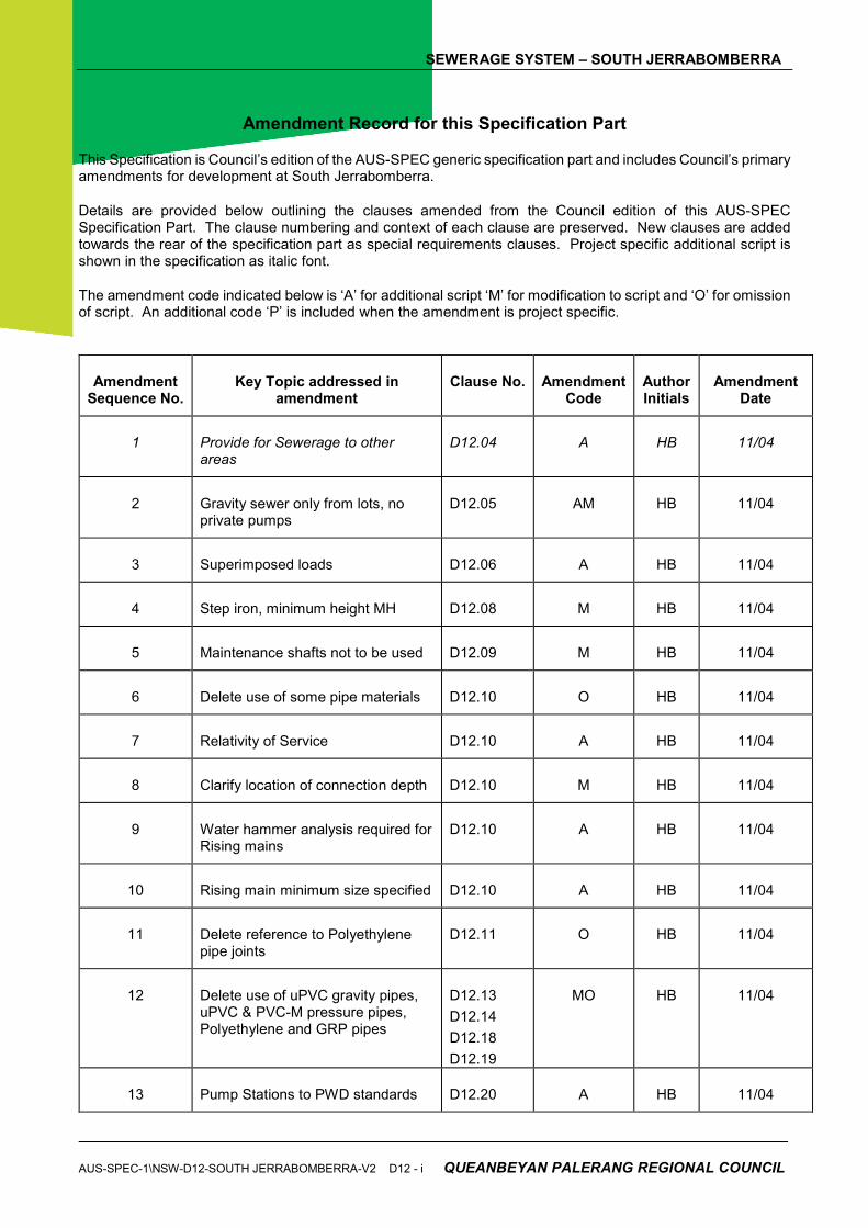
Amendment Record for this Specification Part
This Specification is Council’s edition of the AUS-SPEC generic specification part and includes Council’s primary amendments for development at South Jerrabomberra.
Details are provided below outlining the clauses amended from the Council edition of this AUS-SPEC Specification Part. The clause numbering and context of each clause are preserved. New clauses are added towards the rear of the specification part as special requirements clauses. Project specific additional script is shown in the specification as italic font.
The amendment code indicated below is ‘A’ for additional script ‘M’ for modification to script and ‘O’ for omission of script. An additional code ‘P’ is included when the amendment is project specific.
Amendment Sequence No.
Key Topic addressed in amendment
Clause No. Amendment Code
Author Initials
Amendment Date
1 Provide for Sewerage to other areas
D12.04 A HB 11/04
2 Gravity sewer only from lots, no private pumps
D12.05 AM HB 11/04
3 Superimposed loads D12.06 A HB 11/04
4 Step iron, minimum height MH D12.08 M HB 11/04
5 Maintenance shafts not to be used D12.09 M HB 11/04
6 Delete use of some pipe materials D12.10 O HB 11/04
7 Relativity of Service D12.10 A HB 11/04
8 Clarify location of connection depth D12.10 M HB 11/04
9 Water hammer analysis required for Rising mains
D12.10 A HB 11/04
10 Rising main minimum size specified D12.10 A HB 11/04
11 Delete reference to Polyethylene pipe joints
D12.11 O HB 11/04
12 Delete use of uPVC gravity pipes, uPVC & PVC-M pressure pipes, Polyethylene and GRP pipes
D12.13
D12.14
D12.18
D12.19
MO HB 11/04
13 Pump Stations to PWD standards D12.20 A HB 11/04
SEWERAGE SYSTEM – SOUTH JERRABOMBERRA
QUEANBEYAN PALERANG REGIONAL COUNCIL D12 - ii AUS-SPEC-1\NSW-D12-SOUTH JERRABOMBERRA –V2
Amendment Sequence No.
Key Topic addressed in amendment
Clause No. Amendment Code
Author Initials
Amendment Date
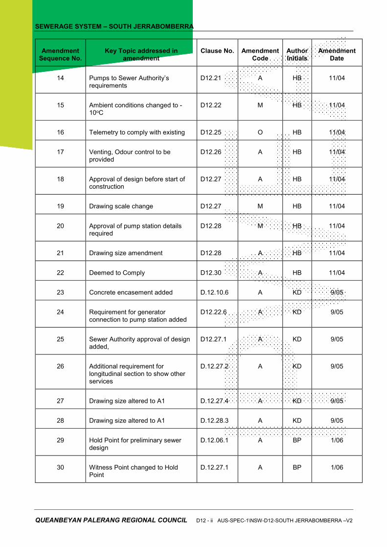
14 Pumps to Sewer Authority’s requirements
D12.21 A HB 11/04
15 Ambient conditions changed to -10oC
D12.22 M HB 11/04
16 Telemetry to comply with existing D12.25 O HB 11/04
17 Venting, Odour control to be provided
D12.26 A HB 11/04
18 Approval of design before start of construction
D12.27 A HB 11/04
19 Drawing scale change D12.27 M HB 11/04
20 Approval of pump station details required
D12.28 M HB 11/04
21 Drawing size amendment D12.28 A HB 11/04
22 Deemed to Comply D12.30 A HB 11/04
23 Concrete encasement added D.12.10.6 A KD 9/05
24 Requirement for generator connection to pump station added
D12.22.6 A KD 9/05
25 Sewer Authority approval of design added,
D12.27.1 A KD 9/05
26 Additional requirement for longitudinal section to show other services
D.12.27.2 A KD 9/05
27 Drawing size altered to A1 D.12.27.4 A KD 9/05
28 Drawing size altered to A1 D.12.28.3 A KD 9/05
29 Hold Point for preliminary sewer design
D.12.06.1 A BP 1/06
30 Witness Point changed to Hold Point
D.12.27.1 A BP 1/06
SEWERAGE SYSTEM – SOUTH JERRABOMBERRA
AUS-SPEC-1\NSW-D12-SOUTH JERRABOMBERRA-V2 D12 - iii QUEANBEYAN PALERANG REGIONAL COUNCIL
Amendment Sequence No.
Key Topic addressed in amendment
Clause No. Amendment Code
Author Initials
Amendment Date
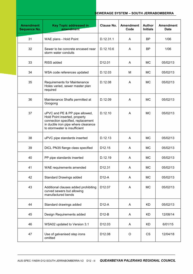
31 WAE plans - Hold Point D.12.31.1 A BP 1/06
32 Sewer to be concrete encased near storm water conduits
D.12.10.6 A BP 1/06
33 RISS added D12.01 A MC 05/02/13
34 WSA code references updated D.12.03 M MC 05/02/13
35 Requirements for Maintenance Holes varied, sewer master plan required
D.12.08 A MC 05/02/13
36 Maintenance Shafts permitted at Googong
D.12.09 A MC 05/02/13
37 uPVC and PE & PP pipe allowed, Hold Point inserted, property connection specified, replacement in ductile iron pipe where clearance to stormwater is insufficient
D.12.10 A MC 05/02/13
38 uPVC pipe standards inserted D.12.13 A MC 05/02/13
39 DICL PN35 flange class specified D12.15 A MC 05/02/13
40 PP pipe standards inserted D.12.19 A MC 05/02/13
41 WAE requirements amended D12.31 A MC 05/02/13
42 Standard Drawings added D12-A A MC 05/02/13
43 Additional clauses added prohibiting curved sewers but allowing manufactured bends
D12.07 A MC 05/02/13
44 Standard drawings added D12-A A KD 05/02/13
45 Design Requirements added D12-B A KD 12/08/14
46 WSA02 updated to Version 3.1 D12.03 A KD 6/01/15
47 Use of galvanised step irons omitted
D12.08 O CS 12/04/18


SEWERAGE SYSTEM – SOUTH JERRABOMBERRA
AUS-SPEC-1\NSW-D12-SOUTH JERRABOMBERRA-V2 D12 - v QUEANBEYAN PALERANG REGIONAL COUNCIL
DEVELOPMENT DESIGN SPECIFICATION D12 –
SEWERAGE SYSTEM – SOUTH JERRABOMBERRA
CLAUSE CONTENTS PAGE
GENERAL ............................................................................................................................. 1
D12.01 SCOPE .................................................................................................................................................... 1
D12.02 OBJECTIVE ............................................................................................................................................. 1
D12.03 REFERENCE AND SOURCE DOCUMENTS ......................................................................................... 2
DESIGN CRITERIA ............................................................................................................... 5
D12.04 GENERAL ................................................................................................................................................ 5
D12.05 DETERMINATION OF AREA TO BE SERVED ................................................................................... 5D
12.06 DESIGN LOADING .................................................................................................................................. 5
D12.07 SEWER ALIGNMENT (WSAA 02 Part 1, section 4.3) ............................................................................ 6
D12.08 MAINTENANCE HOLES (MHs) (WSAA 02 Part 1, section 6.6) ............................................................. 6
D12.09 MAINTENANCE SHAFTS (MSs), MAINTENANCE CHAMBERS (MCs AND TERMINAL
MAINTENANCE SHAFTS (TMSs) .......................................................................................................... 7
D12.10 PIPELINE (WSAA 02 Part 2) ................................................................................................................... 7
D12.11 JOINTS .................................................................................................................................................... 9
D12.12 MINE SUBSIDENCE AREAS AND AREAS OF SLIPPAGE ................................................................... 9
MATERIALS .......................................................................................................................... 9
D12.13 UNPLASTICISED PVC (uPVC) GRAVITY PIPE ..................................................................................... 9
D12.14 UNPLASTICISED AND MODIFIED PVC (uPVC and PVC-M) PRESSURE PIPE................................ 10
D12.15 DUCTILE IRON (DI) PIPE AND FITTINGS ........................................................................................... 10
D12.16 VITRIFIED CLAY (VC) PIPES AND FITTINGS ..................................................................................... 10
D12.17 STEEL PIPE AND FITTINGS ................................................................................................................ 10
D12.18 POLYETHYLENE PIPE AND FITTINGS ............................................................................................... 10
D12.19 GLASS REINFORCED PLASTIC (GRP) PIPE AND FITTINGS ........................................................... 10
PUMP STATIONS ............................................................................................................... 11
D12.20 GENERAL .............................................................................................................................................. 11
D12.21 PUMP .................................................................................................................................................... 12
D12.22 ELECTRICAL ......................................................................................................................................... 12
D12.23 WATER SUPPLY ................................................................................................................................... 13
D12.24 LADDERS .............................................................................................................................................. 13
D12.25 TELEMETRY ......................................................................................................................................... 13
D12.26 OTHER APPURTENANCES ................................................................................................................. 13
SEWERAGE SYSTEM – SOUTH JERRABOMBERRA
QUEANBEYAN PALERANG REGIONAL COUNCIL D12 - vi AUS-SPEC-1\NSW-D12-SOUTH JERRABOMBERRA –V2
DOCUMENTATION ............................................................................................................. 14
D12.27 SEWERAGE SYSTEM .......................................................................................................................... 14
D12.28 PUMP STATION .................................................................................................................................... 15
D12.29 ASSET REGISTER ................................................................................................................................ 16
SPECIAL REQUIREMENTS ............................................................................................... 16
D12.30 DEEMED TO COMPLY ......................................................................................................................... 16
D12.31 WORK AS EXECUTED PLANS ............................................................................................................ 16
D12.32 RESERVED ........................................................................................................................................... 16
ANNEXURES ...................................................................................................................... 18
D12-A. STANDARD DRAWINGS ...................................................................................................................... 18
D12-B SEWER DESIGN REQUIREMENTS 22

SEWERAGE SYSTEM – SOUTH JERRABOMBERRA
AUS-SPEC-1\NSW-D12-SOUTH JERRABOMBERRA-V2 D12 -1 QUEANBEYAN PALERANG REGIONAL COUNCIL
DEVELOPMENT DESIGN SPECIFICATION D12
SEWERAGE SYSTEM – SOUTH JERRABOMBERRA – VERSION 2
GENERAL
D12.01 SCOPE
1. The work to be executed under this Specification consists of the design of a sewerage system either as a stand-alone project or part of a development.
Design
2. The Specification contains procedures for the design of the following elements of the sewerage system:
(a) Gravity sewers including junctions and property connection sewers;
(b) Common effluent sewers both gravity and pressurised;
(c) Reduced Infiltration Sewerage Systems (RISS);
(d) Vacuum sewer system;
(e) Maintenance holes, maintenance chambers, maintenance shafts, flow gauging chambers and other structures;
(f) Rising mains; and
(g) Pump stations.
Elements
3. The design of gravity sewer systems and pump station components shall comply with the Water Services Association of Australia’s publication SEWERAGE CODE OF AUSTRALIA unless specified otherwise herein and should be constructed in accordance with the DEVELOPMENT CONSTRUCTION SPECIFICATION - SEWERAGE SYSTEM – VERSION 2.
Compliance
4. Where the Specification forms part of a contract attracting Government Grant funds, the Principal shall identify
(a) Items which are not of the least cost option, that
(i) Are intended to have a much longer design life than the normal asset service life detailed in the Asset Management Guidelines of the International Infrastructure Management Manual.
(ii) Do not meet the project objectives and the requirements of the various Authorities for the least Net Present Value (NPV) but may become the preferred option for construction.
(b) Particular equipment which is procured without relevant competition through tendering.
(c) Duplication of equipment or unit processes in a system configuration.
Subsidised Schemes
D12.02 OBJECTIVE
1. The objective of the sewerage system is to transport sewage or effluent from domestic properties to the treatment plant in accordance with all current relevant legislation. Consumer requirements shall be met by providing a sewer main and allowing an appropriate point of connection for each individual property.
Sewerage System

SEWERAGE SYSTEM – SOUTH JERRABOMBERRA
QUEANBEYAN PALERANG REGIONAL COUNCIL D12 - 2 AUS-SPEC-1\NSW-D12-SOUTH JERRABOMBERRA-V2
D12.03 REFERENCE AND SOURCE DOCUMENTS
1. Documents referenced in this Specification are listed below whilst being cited in the text in the abbreviated form or code indicated. The Designer shall possess, or have access to, the documents required to comply with this Specification.
Documents
2. References to the SEWERAGE CODE OF AUSTRALIA are made where there are parallel sections or equivalent clauses to those in this Specification. Where not called up as part of this Specification, these references are identified by part and section numbers and enclosed in brackets thus (WSAA Part, Section).
Sewerage Code
(a) Council Specifications C402 - Development Construction Specification Sewerage System –
Version 2.
The Designer shall include the requirements of the DEVELOPMENT CONSTRUCTION SPECIFICATION - SEWERAGE SYSTEM – VERSION 2.
(b) Australian Standards
References in this Specification or the Drawings to Australian Standards are noted by their prefix AS or AS/NZS. (WSA 02 Part 0 section III).
The Designer shall use the latest edition of the Australian Standards including amendments and supplements, unless specified otherwise in this Specification. AS 1102 - Graphical symbols for electrotechnical documentation
(various) AS 1210:1997 Pressure vessels
AS 1214:1983 - Hot dipped galvanised coatings on threaded fasteners (ISO metric coarse thread series)
AS/NZS 1260:2009 PVC pipes and fittings for drain, waste and vent applications AS 1281 - Cement mortar lining of steel pipes and fittings. AS 1444 - Wrought alloy steels – Standard, hardenability (H) series and
hardened and tempered to designated mechanical properties
AS/NZS 1477:2006 PVC pipes and fittings for pressure applications AS 1579:2001 - Arc welded steel pipes and fittings for water and wastewater. AS/NZS 1594 - Hot rolled steel flat products AS 1631 - Cast grey and ductile iron non-pressure pipe and fittings AS 1646:2007 - Elastomeric seals for waterworks purposes AS 1657:1992 - Fixed Platforms, walkways, stairways and ladders – Design,
construction and installation AS 1741 - Vitrified clay pipes and fittings with flexible joints - Sewer
quality. AS 2032:2006 - Installation of PVC pipe systems AS 2129:2000 - Flanges for pipes, valves and fittings AS 2200:2006 - Design charts for water supply and sewerage AS/NZS 2280:2004 Ductile iron pressure pipes and fittings AS/NZS 2566. Buried flexible pipelines AS/NZS 2566.1:1998 - Structural design AS 2634 - Chemical plant equipment made from glass-fibre reinforced
plastics (GRP) based on thermosetting resins AS/NZS 2648.1:1995 Underground marking tape; Part 1: Non-detectable tape
AS 2832 Cathodic protection of metals AS 2832.1-2004 Pipes and cables AS 2832.2-2003 Compact buried structures
AS 2837 - Wrought alloy steels – Stainless steel bars and semi-finished products
Australian Standards
SEWERAGE SYSTEM – SOUTH JERRABOMBERRA
AUS-SPEC-1\NSW-D12-SOUTH JERRABOMBERRA-V2 D12 -3 QUEANBEYAN PALERANG REGIONAL COUNCIL
AS 2865-2009 Confined spaces AS/NZS 3000:2007 Electrical installations (known as the Australian/New
Zealand Wiring Rules). AS/NZS 3111:2009 Approval and test specification - Miniature overcurrent
circuit-breakers. AS/NZS 3190:2009 Approval and test specification - Residual current devices
(current-operated earth-leakage devices) AS 3439 Low voltage switchgear and controlgear assemblies AS 3439.1-2002 Type-tested and partially type-tested assemblies
AS/NZS 3500 - National Plumbing and Drainage Code AS/NZS 3500.2:2003 Sewerage
AS 3518 - Acrylonitrile Butadienne Styrene (ABS) pipes and fittings for pressure applications
AS 3518.1 – Pipes AS 3518.2 - Solvent cement fittings AS 3571 - Glass filament reinforced thermosetting plastics (GRP) pipes
- Polyester based - Water supply, sewerage and drainage applications
AS 3600 :2009 Concrete structures AS 3680: 2008 - Polyethylene sleevings for ductile iron pipelines. AS 3735 - Concrete structures for retaining liquid
AS 3735 Supp1-2001 Concrete structures retaining liquids - Commentary (Supplement to AS 3735-2001)
AS/NZS 3862:2002 External fusion-bonded epoxy coating for steel pipes AS/NZS 3879:2006 Solvent Cements and Priming Fluids for PVC (PVC-U and
PVC-M) and ABS pipes and fittings AS 3996:2006 - Metal access covers, road grates and frames.
AS 4024.1-2006 Series: Safety of machinery (26 parts) AS/NZS 4058:2007 Precast concrete pipes (pressure and non pressure) AS 4060:1992 - Loads on buried vitrified clay pipes. AS 4087:2004 - Metallic flanges for waterworks purposes AS 4100:1998 - Steel structures AS/NZS 4129:2008 Fittings for polyethylene (PE) pipes for pressure applications. AS/NZS 4130:2009 Polyethylene (PE) pipes for pressure applications. AS/NZS 4131 - Polyethylene (PE) compounds for pressure pipes and
fittings. AS/NZS 4158:2003 Thermal-bonded polymeric coatings on valves and fittings for
water industry purposes AS/NZS 4321 - Fusion-bonded medium-density polyethylene coating and
lining for pipes and fittings AS/NZS 4331 Metallic flanges AS/NZS 4331.1:1995 Steel flanges AS 4441-2008 Oriented PVC (PVC-O) pipes for pressure applications
AS/NZS 4765:2007 Modified PVC (PVC–M) pipes for pressure applications AS 4883 – 2008 Air valves for sewerage
AS/NZS 5065:2005 Polyethylene and polypropylene pipes and fittings for drainage and sewerage applications
AS/NZS 60269 Low voltage fuses AS/NZS 60269.1: 2005 General requirements AS 60947 Low voltage switchgear and controlgear AS 60947.2- 2005 Circuit-breakers AS 60947.5.1 Control circuit devices and switching elements -
Electromechanical control circuit devices AS/NZS 61000 Electromagnetic compatibility (EMC) AS/NZS 61000.4.6: 2008 Testing and measurement techniques - Immunity to
conducted disturbances, induced by radio-frequency fields
AS/NZS 61000.6.2: 2006 Generic standards - Immunity for industrial environments
SAA HB 48: 1999 Steel structures design handbook.
SEWERAGE SYSTEM – SOUTH JERRABOMBERRA
QUEANBEYAN PALERANG REGIONAL COUNCIL D12 - 4 AUS-SPEC-1\NSW-D12-SOUTH JERRABOMBERRA-V2
Where not otherwise specified in this document, the Contractor shall use the latest Australian Standard available within two weeks of close of tenders.
(c) Other
Institute of Public Works Engineering Australia (IPWEA) - Streets Opening Conference Information Bulletin on Codes
and Practices (Sections 3 and 4 detailing locations and depths of other services).
NSW Department of Commerce MEW E101 - Electrical Services Minimum Requirements
PWD - Safety Guidelines for fixed ladders, stairways, platforms and walkways for use in sewage treatment Works, pumping stations and maintenance holes.
PWD-SD - Public Works Department Manual of Practice – Sewage Design.
PWD-PSD - Public Works Department Manual of Practice – Sewage Pumping Station Design (May 1986).
WS-SPEC - Technical Requirements (TRs) and Strategic products Specifications (WSAA)
Water Services Association of Australia (WSA) WSA 01 – 2004 - Polyethylene Pipeline Code WSA 02 - 2014 - Gravity Sewerage Code of Australia – Version3.1
WSA 03 - 2011 Water Supply Code of Australia, Version 3.1 WSA 04 - 2005 - Sewage Pumping Station Code of Australia – Version 2.1 WSA 05 – 2013 Conduit Inspection Reporting Code of Australia – Version
3.1 WSA 06 – 2008 - Vacuum Sewerage Systems. WSA 07 – 2007 - Pressure Sewerage Code of Australia – Version 1.1 Building Codes Board of Australia
- Building Code of Australia - PART E1, Fire Fighting Equipment.
Sydney Water Technical Specification for Low Infiltration Sewer Systems – Version 6.0 (2012) Standard Specification PCS100 – Protective Coating Standard Standard Specification SS210 – Corrosion Protection and Rehabilitation of
Maintenance Holes
(d) Standard Drawings
Sydney Water Low infiltration Sewer System drawings are to be used in preference to SEWERAGE CODE OF AUSTRALIA drawings and DPWS Standard Drawings (WSA 02, Part 1).
Drawings

SEWERAGE SYSTEM – SOUTH JERRABOMBERRA
AUS-SPEC-1\NSW-D12-SOUTH JERRABOMBERRA-V2 D12 -5 QUEANBEYAN PALERANG REGIONAL COUNCIL
DESIGN CRITERIA
D12.04 GENERAL
1. The design shall be in accordance with the SEWERAGE CODE OF AUSTRALIA, Sydney Water Technical Specification for Low Infiltration Sewer Systems or PWD-SD and PWD-PSD unless specified otherwise herein (WSA 02 Part 1).
Standard
2. Except where specified otherwise, the division of responsibilities between the Sewer Authority and the Designer shall be in accordance with the SEWERAGE CODE OF AUSTRALIA (WSA 02 Part 1, section 1.2).
Responsibility
3. The Designer shall confirm the design criteria with the Sewer Authority and shall design a gravity pipeline distribution system with pump stations and rising mains, where necessary to comply with the requirements of this Specification, to transport fresh sewage, or common effluent, for treatment.
Gravity System
4. Pressurised common effluent or vacuum systems shall only be considered after consultation with the Sewer Authority.
Pressurised or Vacuum System
5. The Designer shall not provide for common effluent or vacuum discharges to gravity sewers or conventional wastewater treatment plants without the concurrence of the Sewer Authority.
Discharges to Gravity Sewers
D12.05 DETERMINATION OF AREA TO BE SERVED
1. The area to be served shall be determined in accordance with PWD-SD except that the Sewer Authority may require provision for an upstream sewer. In the design brief the Sewer Authority will indicate the level and size of existing pipe as well as anticipated flows to be allowed for in the design (WSA 02 Part 1, section 2.4.2). Alternatively, the Authority may require the designer to determine the future and ultimate upstream sewer loading and provide adequate allowance for such loadings to the satisfaction of the approving authority.
Upstream Sewer
2. The depth of sewer shall be sufficient to allow a minimum of 90 per cent of each lot to be serviced.
Depth
3. All lots shall be able to be served by gravity sewers. Private pump stations delivering to the Sewer Authority mains will not be permitted.
Provision of Sewerage
D12.06 DESIGN LOADING
1. Design requirements are listed in Annexure D12-B.
The Designer shall obtain the concurrence of the Sewer Authority for the flow to be used for the design of sewers serving industrial areas and developments not specifically listed in the SEWERAGE CODE OF AUSTRALIA or PWD-SD (WSA 02 Part 1, section 3).
Flows
2. The design shall take account of AS 2200, AS/NZS 2566.1, AS 3500, AS 3735, the SEWERAGE CODE OF AUSTRALIA and, where design elements are not covered elsewhere in these codes, PWD-SD and PWD-PSD. The approval of preliminary design constitutes a HOLD POINT [see 12.27 (1)].
Design Codes
(HP)
3. The design shall take account of loads on the pipeline from all sources, including superimposed loads from stormwater pipes, water supply mains and other utility services.
Superimposed Loads

SEWERAGE SYSTEM – SOUTH JERRABOMBERRA
QUEANBEYAN PALERANG REGIONAL COUNCIL D12 - 6 AUS-SPEC-1\NSW-D12-SOUTH JERRABOMBERRA-V2
D12.07 SEWER ALIGNMENT (WSAA 02 Part 1, section 5.2)
1. Where it is necessary for sewers to be located outside the development, the Designer shall obtain written approval from the affected property owner. Preparation of any application for approval from an affected property owner shall constitute a WITNESS POINT. The Principal shall advise whether the option to review and direct on the application is taken at the time of notification by the Designer.
Consent of Owner
(WP)
2. Where sewers are proposed to be located within existing road reserves, the Designer shall check that the sewers do not conflict with other utility services and locate the sewers in accordance with established protocols (WSA 02 Part 1, section 5.3).
Road Reserve
3. Sewers located on private property must be located in an easement of minimum width three (3) metres. Unless there are compelling reasons to the contrary the sewer shall be located in the centre of the easement. A Registered Surveyor shall survey easements and pipelines (WSA 02, Part 1, Section 5.2.8).
Easement
4. Where control of the trench width is practical or effective, the design may be based on wide trench condition. The Designer shall call up the need, in the Construction Specification, for the Contractor to supply special construction control with a method statement when there is economic justification to design to narrow trench condition.
5. Sewers shall be laid in a straight horizontal and straight vertical alignment. Curved sewers shall not be provided in the design without the prior written consent of the Sewer Authority (WSA 02, Part 1, sections 5.3.8 & 5.6.7). The gaining of approval for curved sewers constitutes a HOLD POINT.
6. Manufactured bends are permitted adjacent to a maintenance structure for reticulation sewers (WSA 02, Part 1, sections 5.3.8 & 5.6.7).
Trench Width
Alignment
(HP)
Manufactured Bends
D12.08 MAINTENANCE HOLES (MHs) (WSA 02 Part 1, section 7)
1. Maintenance holes shall generally be placed on gravity sewers as specified in WSA 02, Part 1, section 7.3, except that
• the maximum spacing between any two consecutive maintenance holes shall be 180 m;
• maintenance holes shall be provided at all intersections of reticulation sewers;
• maintenance holes shall be provided at all changes in vertical grade;
• maintenance holes shall be provided at all changes in sewer reticulation horizontal direction except where a maintenance shaft or maintenance chamber is permitted to be installed instead;
• maintenance holes shall be provided where required to provide flow gauging stations (WSA 02, Part 1, section 7.10) The flow gauging stations shall comply with the requirements of Sydney Water Technical Specification for Low Infiltartion Sewer Systems;
• Maintenance holes and flow gauging chambers shall be completely "cast in situ" with water seals (puddle flanges, hydrophilic seals, and the like) placed on all pipe penetrations into the chamber; and
Emergency overflow management facilities shall be provided at all sensitive locations and shall comply with the requirements of the Sydney Water Technical Specification for Low
Spacing
Flow Gauging
SEWERAGE SYSTEM – SOUTH JERRABOMBERRA
AUS-SPEC-1\NSW-D12-SOUTH JERRABOMBERRA-V2 D12 -7 QUEANBEYAN PALERANG REGIONAL COUNCIL
Infiltration Sewer Systems and the requirements of the NSW Environment Protection Authority (EPA)
2. All upstream ends of sewers shall terminate in a maintenance hole if the upstream end is more than 80m from the downstream maintenance hole.
Terminal Maintenance Hole
3. Step irons shall be provided to all maintenance holes where the depth from top of cover to the invert of the outlet pipe exceeds 900mm. Step Irons shall be of 24mm diameter cast aluminium or plastic encapsulated.
Step Irons
4. The Designer shall provide for the venting of the sewerage system (WSA 02, Part 1, section 7.5). Maintenance holes which accept pumped discharges shall be vented.
Venting
5. Connections to existing maintenance holes or sewers of the existing sewerage system are to be based on a sewerage master plan. A master plan is to be developed for each subdivision stage and be approved by the Sewer Authority.
Connections to Existing Systems
6. Metal access covers shall be manufactured in accordance with AS 3996. Access Covers
D12.09 MAINTENANCE SHAFTS (MSs), MAINTENANCE CHAMBERS (MCs) AND TERMINAL MAINTENANCE SHAFTS (TMSs) (WSA 02 Part 7)
1. Maintenance shafts and maintenance chambers may be provided between maintenance holes in accordance with the requirements of WSA 02, Section 7, Table 7.1 to limit the distance between the maintenance hole and another access structure to 80 m;2. The maximum distance between consecutive maintenance shafts shall be 60 m;
3. A maintenance shaft or maintenance chamber may be located at a change of horizontal direction in the sewer main of 50 or below in lieu of a maintenance hole: and
4. A terminal maintenance shafts shall be used where the dead end of a main is greater than 30 m and less than 80 m from the downstream maintenance hole.
5. The maximum depth of a maintenance shaft, maintenance chamber or terminal maintenance shaft shall be 3.0 metres.
6. The maximum loading from high-level connections on a maintenance shaft, maintenance chamber or terminal maintenance shaft shall be 20 EP. Connections shall be limited to the following –
• One DN 150 sewer and/ one property connection; or
• Two property connections.
D12.10 PIPELINE (WSA 02 Part 1.4)
1. Pipes and fittings for sewerage systems shall be of unplasticised PVC, ductile iron, polyethylene or polypropylene. The material specifications for each pipe type are provided in Clauses D12.13 to D12.19 inclusive. The choice of pipe type constitutes a HOLD POINT.
Type
(HP)
2. Asbestos cement pipe and fittings shall not be used. Asbestos Cement
3. Concrete pipes, fibre reinforced concrete pipes, steel pipes and vitreous clay pipes shall not be used.
Other Pipes
SEWERAGE SYSTEM – SOUTH JERRABOMBERRA
QUEANBEYAN PALERANG REGIONAL COUNCIL D12 - 8 AUS-SPEC-1\NSW-D12-SOUTH JERRABOMBERRA-V2
4. Pipelines shall be buried. Above ground sewers may be designed in a gravity system only where other options are less practical (WSA 02, Part 1, section 9.8). The Designer shall obtain the concurrence of the Sewer Authority to any proposed above ground sewer. The action to provide for above ground sewers constitutes a HOLD POINT.
Buried Pipes
(HP)
5. The Designer shall show on the Drawings the extent of external protection required to be undertaken by the Contractor. External protection shall be shown to comply with the DEVELOPMENT CONSTRUCTION SPECIFICATION - SEWERAGE SYSTEM – Version 2
External Protection
6. Where sewer pipes or rising mains are to be located in close proximity to other services pipes or where there is the likelihood of the pipes not being recognised as sewerage pipes, the Designer shall provide for the pipes to be colour coded and shown on the Drawings accordingly.
Where sewer pipes or rising mains are to be located in close proximity to or cross other service mains clearances shall be maintained in accordance with WSA 02, Section 4.4.5.2. Sewer pipes shall not be located above water mains without the prior written approval of the Water Authority.
Where sewer pipes clearance to stormwater conduits is less than 0.6 metres the sewer shall be constructed in ductile iron cement lined pipe.
Colour Coding
Relativity of Services
7. Piers for any above ground sewer pipeline shallhave structural details provided on the drawings.
Piers
8. Property connections shall utilise the buried interface method to the following requirements –
• Where the main is not a deep main and is located within private property or in the verge directly outside private property the property connection may be DN100 and terminate as a dead end.
• In all other cases the property connection shall be DN150 with a rodding point provided at the termination by the use of a 450 junction or a terminal maintenance shaft (TMS).
• A property connection shall not be designed to provide connection off another property connection aa a Y connection without the prior written consent of the Sewer Authority being obtained prior to design. Where permitted, the junction off the other property connection must not be sitediin a road carriageway and must limit the length of the sideline to 6 m.
• The pipeline alignment shall be such that no property connection sewer is to be more than 25 m in length.
• Where longer property connections are required, they shall be designed to the same standards as reticulation sewers and shall be provided with maintenance access. (WSA 02, Part 1, section 6).
Property Connection
9. The Designer shall ensure that the point of property connection to the pipeline shall be not more than 1500mm in depth below the finished surface of the property served.
Property Connection Depth
10. The Designer shall allow for adequate working area, waste removal and transport arrangements where scouring points or inspection pipe locations are nominated.
Special Allowances
11. The Designer shall design thrust blocks to the requirements of WSA standard drawing WAT-1205.
Thrust Blocks

SEWERAGE SYSTEM – SOUTH JERRABOMBERRA
AUS-SPEC-1\NSW-D12-SOUTH JERRABOMBERRA-V2 D12 -9 QUEANBEYAN PALERANG REGIONAL COUNCIL
12. The Designer shall provide for surge control by specifying an appropriate rising main material and class selection. Water hammer analysis shall be carried out for all rising mains. The analysis shall be provided to the Sewer Authority.
Surge Control Method
13. Rising mains shall have a minimum diameter of 100DN. Rising Main Minimum size
D12.11 JOINTS
1. Gravity sewers and rising mains shall generally be spigot and socket joints with rubber rings (elastomeric) complying with AS 1646.
Rubber Ring
2. Flanged joints connecting pipes, fittings, valves and pumps shall comply with AS 2129 (Flanges shall be Table C) or AS 4087, Class 16, as appropriate.
Flanges
3. The concurrence of the Sewer Authority shall be obtained for the type of joint to be used
D12.12 MINE SUBSIDENCE AREAS AND AREAS OF SLIPPAGE
1. The Designer shall accommodate the movement associated with the ground strain for the area, as advised by the Mine Subsidence Board for sewerage jointing systems in proclaimed Mine Subsidence Areas, or in a known or expected area of subsidence or slippage. The design ground strain for the development shall be detailed on the Drawings.
Ground Strain
2. The pipe jointing system selected shall be capable of accepting ground movements, without impairing the water tightness of the joint, for the ground strain as advised by the Mine Subsidence Board. For areas with high ground strains a pipe jointing system using shorter effective length pipes and/or deep socket fittings shall be used. This action constitutes a WITNESS POINT. The Principal shall advise at the time of notification by the Designer whether the option to confer is required.
Pipe Jointing System
(WP)
3. Where the Mines Subsidence Board does not cover an area of known, or suspected, subsidence or slippage, the above requirements shall still apply.
Areas Applicable
MATERIALS
D12.13 UNPLASTICISED PVC (uPVC) GRAVITY PIPE
1. Unplasticized PVC (PVC-U) pipe shall be specified for sewer gravity mains of 150 mm and 225 mm diameter and shall be manufactured in accordance with AS/NZS 1260, designed in accordance with AS/NZS 2566.1 and with elastomeric seal spigot and socket joints (WSA 02, Part 1, Section 4.6). The pipe shall be not less than Class SN 8.
2. Where PVC pipe is used in conjunction with DI fittings, the Designer shall ensure the jointing system is appropriate.
3. Fittings for use with PVC pipe shall be elastomeric seal jointed.
Standard
Ductile Iron Pipe Compatibility
Fittings
D12.14 UNPLASTICISED (uPVC) AND MODIFIED PVC (PVC-M) PRESSURE PIPE
1. uPVC pressure pipe shall not be used Not Permitted

SEWERAGE SYSTEM – SOUTH JERRABOMBERRA
QUEANBEYAN PALERANG REGIONAL COUNCIL D12 - 10 AUS-SPEC-1\NSW-D12-SOUTH JERRABOMBERRA-V2
2. PVC-M pipe may be used for pressure mains. And shall comply with AS/NZS 4765 and shall be of the class and size shown on the Drawings
Standard
D12.15 DUCTILE IRON (DI) PIPE AND FITTINGS
1. Ductile iron pipes and fittings shall be specified for all sewer rising mains and are to be manufactured and cement mortar lined in accordance with AS/NZS 2280 minimum and shall specify PN35 Flanged Class (WSA 02, Part 1, Section 4.5).
Standard
2. The Designer shall specify cement mortar lining in accordance with AS 1281, or fusion-bonded medium density polyethylene to AS/NZS 4321. External protection shall be epoxy coating to AS 3862 where not otherwise specified as sleeved or wrapped, taking into account the type of corrosion protection required.
Corrosion Protection
3. Generally, pipe and fitting joints shall be specified to be spigot and socket type using a rubber ring (elastomeric) push in seal made of natural rubber or ethylene propylene rubber with compounds complying with AS 1646. The seal shall be a single jointing component shaped to provide both groove lock and seal mechanisms.
Joints
4. Flanges shall be specified to be manufactured in accordance with AS 2129 Table C. Bolts and nuts for flanged joints shall be in accordance with AS 2129 and galvanised in accordance with AS 1214 or stainless steel in accordance with AS 2837 as for pumps specified in the specification DEVELOPMENT CONSTRUCTION SPECIFICATION – SEWERAGE SYSTEM – Version 2.
Flanges
D12.16 VITRIFIED CLAY (VC) PIPES AND FITTINGS
1. Vitrified Clay (VC) pipes and fittings shall not be used Not Permitted
D12.17 STEEL PIPE AND FITTINGS
1. Steel pipes and fittings shall not be used. Not Permitted
D12.18 POLYPROPYLENE PIPE AND FITTINGS
1. (a) Twin walled, corrugated polypropylene pipes and fittings may be used for sewer gravity trunk mains 225 mm or greater in diameter and shall be manufactured to comply with AS/NZS 5065 and designed to AS/NZS 2566.1 . (WSA 02, Part 1, Section 4.8).
(b) Polyethylene pipes shall not be used. .
PP Standard
Not permitted
D12.19 GLASS REINFORCED PLASTIC (GRP) PIPE AND FITTINGS
1. Glass filament reinforced thermosetting plastic (GRP) pipes may be used for gravity sewer mains and pressure mains..
Standard
2. Glass filament reinforced thermosetting plastics (GRP) pipes shall comply with AS 3571 and shall be of the class and size shown on the Drawings and installed in accordance with AS/NZS 2566.1 (WSA 02 Part 1, section 4.9).
Standard
SEWERAGE SYSTEM – SOUTH JERRABOMBERRA
AUS-SPEC-1\NSW-D12-SOUTH JERRABOMBERRA-V2 D12 -11 QUEANBEYAN PALERANG REGIONAL COUNCIL
PUMP STATIONS
D12.20 GENERAL
1. The design of sewerage pumping stations and ancillary equipment shall be subject to endorsement by the Sewer Authority. This action constitutes a HOLD POINT The Designer shall take into account access, site maintenance and restoration, easement, power supply and working area when locating pump stations in road reserves or on private property..
Location
(HP)
2. Where not provided as a Vacuum Sewerage System, the Designer shall provide for all pump stations to be of the single wet well submersible pump style with self contained freestanding switchboards suitable for external use. Pump Stations shall be designed in accordance with PWD – PSD. The Designer shall provide for the construction of the pump well after taking into consideration the ground and site conditions.
Type
3. Cast in situ concrete fabrication shall
(a) Use Sulfate resistant or low heat (LH) (special class) concrete.
(b) Have all internal surfaces epoxy lined to current edition of Sydney Water’s Protective Coating Standard. The colour can range from “off-white” to “light grey”.
(c) Have all pipe and equipment penetrations tested for water tightness.
(d) Have water seals (puddle flanges, hydrophilic seals, and the like)20 placed on all pipe and equipment penetrations.
In Situ Fabrication
4. Preformed components or systems, complying with the Drawings, if any, may be used in lieu of in-situ construction provided:
Preformed Components
(a) The proposed precast pump station make and model are approved by the Sewer Authority for use prior to its incorporation in the sewerage system design.
(b) Preformed concrete wall units are to be manufactured to AS 4058. The Designer shall take into account the cover requirements for reinforcing steel and cement types
(c) Precast segments shall be joined using the manufacturer’s recommended practice and internal surfaces patched to form a continuous flush surface.
(d) The Designer shall ensure selected components make a watertight system Water seals (puddle flanges, hydrophilic seals, and the like) shall be placed on all pipe and equipment penetrations
(e) All pipe and equipment penetrations shall be fabricated and tested in the factory for water tightness.
5. Where the pump station site is exposed to possible flooding, the Designer shall provide for the top of pump well to be one (1) metre above the 1 in 100 year flood level or to such other level as provided by Council’s planning instruments, whichever is the higher.
Protection Against Flooding
6. The Designer shall provide for the design of pump wells against flotation both during the construction/installation stage and whilst operating under flood conditions designed as above.
Protection Against Flotation

SEWERAGE SYSTEM – SOUTH JERRABOMBERRA
QUEANBEYAN PALERANG REGIONAL COUNCIL D12 - 12 AUS-SPEC-1\NSW-D12-SOUTH JERRABOMBERRA-V2
7. Package pump station units may be designed, with the prior concurrence of the Sewer Authority, where the area being serviced is small and/or their inclusion contributes to an overall lesser depth of excavation in the system.
Package Units
8. The Designer shall provide for internal surfaces of wet wells to be prepared and coated with an epoxy paint system approved by the Superintendent. The colour shall range from “off white” to “light grey”. All bolted connections within wet wells shall be stainless steel complying with AS 1449 grade 316.
Surfaces
9. The Designer shall size pipes and pump station capacity to avoid surcharges under design flow conditions. The Designer shall provide for overflows in strict accordance with the conditions of the licence, if any, permitting sewage overflow.
Overflows
10. The Designer shall provide for alarms and signals systems with the concurrence of the Sewer Authority.
Alarms and Signals
D12.21 PUMP
1. The Designer shall specify special requirements, if any, for materials to be used in the pump station, taking into consideration the nature and composition of the sewage to be pumped. Each pump shall be fitted with a flushing valve installed in accordance with the manufacturer’s recommendations.
Special Requirements
2. The Designer shall provide for pump stations to be fitted with suitably sized pumps, consistent with other pumps in service, in conventional duty pump/standby pump arrangement.
Size
3. Each pump shall be capable of passing solids of not less than 75mm diameter unless grinding equipment is incorporated
Impeller Clearance
4. Each pump shall be capable of being removed with the aid of fixed guide rails. Removal
5. Pump sets are to be interchangeable within each pump station. Pumps are to be consistent with other pumps in use by the Sewer Authority. The Sewer Authority will specify the brand and type of pumps to be used.
Inter-changeable
6. The Designer shall design structural steelwork in accordance with HB 48. Structural Steelwork
D12.22 ELECTRICAL
1. Notwithstanding other clauses mentioned herein, the Designer shall be responsible for the design of the equipment as suitable for the purpose. Equipment design shall comply with the requirements of the relevant standard specification.
Design Responsibility
2. The Designer shall provide for Switchgear Control Assembly (SCA), SCA housing and electrical requirements as detailed in the DEVELOPMENT CONSTRUCTION SPECIFICATION- SEWERAGE SYSTEM – VERSION 2.
SCA and Electrical
3. Where more than one (1) item of equipment is designed to form a particular function, all such items of equipment shall be identical and completely interchangeable (eg pilot lights, pushbuttons, relays, etc).
Inter-changeability
4. The switchboard shall be installed visibly and physically accessible above areas at risk of flooding.
Switchboard
5. Ambient conditions shall be within the normally accepted limits of -10°C to +45°C. Ambient Conditions

SEWERAGE SYSTEM – SOUTH JERRABOMBERRA
AUS-SPEC-1\NSW-D12-SOUTH JERRABOMBERRA-V2 D12 -13 QUEANBEYAN PALERANG REGIONAL COUNCIL
6. The switchboard shall be connected to the local electricity supply system.
Nominal system parameters:
(a) 415 volt, 3-phase, 4-wire, 50 Hz, solidly earthed neutral system.
(b) Prospective Fault Current: As specified by the Local Supply Authority.
The switchboard shall provide a generator connection point to allow the pump station to be run via generator in the event of failure of the local electricity supply system.
Connection to Local Supply
7. The works shall be designed in accordance with and subject to the provisions of MEW E101, except where modified by this Specification.
Standards
8. The pump station shall be designed for fully automatic operation in the unmanned condition.
Automatic Operation
D12.23 WATER SUPPLY
1. The Designer shall provide for automatic well washers and flush valves to be installed at each pump station and controlled so that they operate when the duty pump is operating.
Cleaning
2. The Designer shall provide at all pump stations for an adequate water supply for cleaning purposes. This supply shall be protected from contamination due to backflow by the installation of a registered break tank or reduced pressure zone device in accordance with AS 3500.
Contamination Protection
D12.24 LADDERS
1. Ladders shall comply with AS 1657 and applicable Workl Health and Safety legislation (WSA 02 Part 1, section 7.6.9).
Standard
2. If required, the Designer shall set intermediate landings in wells to achieve the minimum head room clearance. Wherever possible, the landing shall be located adjacent to fittings and machinery requiring maintenance.
Ladder Landings
3. Ladder cages shall not be used on ladders in pump station wet wells. Ladder Cages
D12.25 TELEMETRY
1. The Designer shall provide for telemetry requirements in accordance with the schedule supplied by the Sewer Authority.
Schedule
2. The telemetry system is to be compatible with the existing system in use. Compatibility
D12.26 OTHER APPURTENANCES
1. The Designer shall provide for venting and odour control of each pump station, rising main, receiving maintenance holes, and gravity sewers, after consultation with the Sewer Authority.
Venting and Odour Control
2. The Designer shall provide for machinery lifting equipment including pump chains.
Lifting Equipment
SEWERAGE SYSTEM – SOUTH JERRABOMBERRA
QUEANBEYAN PALERANG REGIONAL COUNCIL D12 - 14 AUS-SPEC-1\NSW-D12-SOUTH JERRABOMBERRA-V2
3. The Designer shall provide pressure tapping and gauges for all valves, including isolation and non-return valves and as detailed in the DEVELOPMENT CONSTRUCTION SPECIFICATION-SEWERAGE SYSTEM – VERSION 2.
Gauges
4. The Designer shall take account of the possibility of site flooding ingress and overflow, and Occupational Health and Safety requirements in providing for access and inspection covers.
Covers
DOCUMENTATION
D12.27 SEWERAGE SYSTEM
1. The Principal shall submit, to the Sewer Authority an Application for Certification of Design Drawings under Part 3 Division 2 Section 307 of the Water Management Act 2000, together with four (4) copies of the proposed sewerage system design, including calculations, and obtain approval prior to commencement of construction (WSA 02 Part 1, section 9). This action constitutes a HOLD POINT. Approval of the design by the Sewer Authority will be made by the issue of a compliance certificate under Part 3 Division 2 Section 307 of the Water Management Act 2000.
Review
(HP)
2. The Drawings shall show to scale:
(a) Plan showing: Plan
(1) Lot boundaries and lot numbers
(2) Location and chainage of all maintenance holes, junctions and dead ends
(3) Maintenance hole types
(4) Location and size of all gravity and rising mains and pump stations
(5) Location of vents
(6) Sewer main number and maintenance hole number
(7) Existing sewer mains, junctions and maintenance holes
(8) For level lots, spot levels at the lot extremities to show that at least 90 per cent of the area of the lot can be connected to the sewer by gravity.
(9) Hatching shall show the area of any lot not serviced.
(10) Site contours
(11) Existing and proposed features and services
(12) North point and scale bar
(13) Easement location
(14) Arrangement of other utilities.
(b) Longitudinal section showing: Longitudinal Section
(1) Reduced levels for natural surface and design surfaces at all changes in grade
(2) Maintenance hole locations and type
(3) Maintenance holes numbered in accordance with the Sewer Authority’s Asset Register

SEWERAGE SYSTEM – SOUTH JERRABOMBERRA
AUS-SPEC-1\NSW-D12-SOUTH JERRABOMBERRA-V2 D12 -15 QUEANBEYAN PALERANG REGIONAL COUNCIL
(4) Invert levels for maintenance holes, maintenance shafts and maintenance chambers inlet and outlet
(5) Size, type, class and grade of pipe
(6) Location, invert level and size of all drainage lines, water mains, and other utility services crossing the main
(7) Notation regarding all joining lines
(8) Property ownership
(9) Note upstream ET’s at each maintenance hole
(10) Note “In road” trench conditions
(11) Locations and levels of other services (existing or proposed) relative to the sewer main
(c) General arrangement of pump stations with site plan; concrete outlines; number, make, model and details of pumps; inlet and outlet pipework details and levels; pump cut in; cut out and alarm levels; switchboard location; pump station access details; design starts per hour.
Pump Stations
(d) Details of corrosion protection required for pipes and fittings. Pipe Protection
(e) Areas designated for trenchless pipe installation. Trenchless Installation
3. Detail plans shall be drawn to a scale of 1:500 and longitudinal sections to a horizontal scale of 1:500 and a vertical scale of 1:100.
Drawing Scale
4. Drawings shall be “A1” size for approval with “A3” size copies to be forwarded to the Sewer Authority once the plans have been approved.
Drawing Size
5. Drawings shall be provided also in electronic form after consultation with the Sewer Authority.
Electronic Form
D12.28 PUMP STATION
1. The Principal shall submit, to the Sewer Authority and obtain approval, prior to commencement of the manufacture of any pumps and control equipment, four (4) copies of the following:
Review
a. Switch and Control Gear Assemblies - Proposed fully dimensioned manufacturing details, general arrangement (showing internal/external details) and foundation/gland plate details.
b. Common Control - Complete circuit diagram and description of operation.
c. Schedule of Equipment - Completed as to the equipment to be provided.
d. Other Engineering drawings as required to fully describe the proposed equipment.
The submission of the documents constitutes a HOLD POINT. (HP)
2. The Designer shall take into consideration the technical requirements to minimise all risks associated with entry into confined space.
Risk
SEWERAGE SYSTEM – SOUTH JERRABOMBERRA
QUEANBEYAN PALERANG REGIONAL COUNCIL D12 - 16 AUS-SPEC-1\NSW-D12-SOUTH JERRABOMBERRA-V2
3. Drawings shall be on "A1" size with ”A3” size copies to be forwarded to the Sewer Authority once the plans have been approved. All symbols used shall conform to AS 1102 and all wires and terminals shall be numbered.
Drawing Size
4. Drawings shall also be provided in electronic form after consultation with the Sewer Authority.
Electronic Form
D12.29 ASSET REGISTER
1. The Designer shall provide asset schedules and Drawings in a form consistent with the existing or proposed Asset Register after consultation with the Sewer Authority. (WSA 02 Part 1, section 10.5).
Consistency
SPECIAL REQUIREMENTS
D12.30 WORK AS EXECUTED (WAE) PLANS WAE
1. Full WAE plans for all constructed infrastructure shall be submitted to Council prior to the issue of a Subdivision Certification and/or an Occupation Certificate. The submission of these documents constitutes a HOLD POINT.
(HP)
2. Plans shall be submitted in electronic format in accordance with Council’s Handbook of Drafting Standards.
D12.31 RESERVED
SEWERAGE SYSTEM – SOUTH JERRABOMBERRA
AUS-SPEC-1\NSW-D12-SOUTH JERRABOMBERRA-VERSION 2 D12 -17 QUEANBEYAN PALERANG REGIONAL COUNCIL
ANNEXURE D12- A
STANDARD DRAWINGS
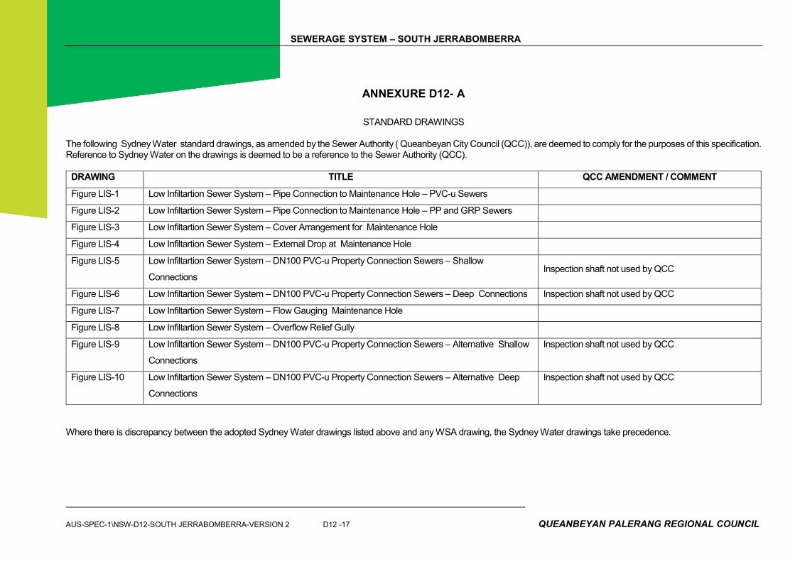
The following Sydney Water standard drawings, as amended by the Sewer Authority ( Queanbeyan City Council (QCC)), are deemed to comply for the purposes of this specification. Reference to Sydney Water on the drawings is deemed to be a reference to the Sewer Authority (QCC).
DRAWING TITLE QCC AMENDMENT / COMMENT
Figure LIS-1 Low Infiltartion Sewer System – Pipe Connection to Maintenance Hole – PVC-u Sewers
Figure LIS-2 Low Infiltartion Sewer System – Pipe Connection to Maintenance Hole – PP and GRP Sewers
Figure LIS-3 Low Infiltartion Sewer System – Cover Arrangement for Maintenance Hole
Figure LIS-4 Low Infiltartion Sewer System – External Drop at Maintenance Hole
Figure LIS-5 Low Infiltartion Sewer System – DN100 PVC-u Property Connection Sewers – Shallow
Connections Inspection shaft not used by QCC
Figure LIS-6 Low Infiltartion Sewer System – DN100 PVC-u Property Connection Sewers – Deep Connections Inspection shaft not used by QCC
Figure LIS-7 Low Infiltartion Sewer System – Flow Gauging Maintenance Hole
Figure LIS-8 Low Infiltartion Sewer System – Overflow Relief Gully
Figure LIS-9 Low Infiltartion Sewer System – DN100 PVC-u Property Connection Sewers – Alternative Shallow
Connections
Inspection shaft not used by QCC
Figure LIS-10 Low Infiltartion Sewer System – DN100 PVC-u Property Connection Sewers – Alternative Deep
Connections
Inspection shaft not used by QCC
Where there is discrepancy between the adopted Sydney Water drawings listed above and any WSA drawing, the Sydney Water drawings take precedence.

SEWERAGE SYSTEM – SOUTH JERRABOMBERRA
QUEANBEYAN PALERANG REGIONAL COUNCIL D12 - 18 AUS-SPEC-1\NSW-D12-SOUTH JERRABOMBERRA-VERSION 2
The following Water Services Association of Australia standard drawings, as amended by Queanbeyan City Council (QCC), are deemed to comply for the purposes of this specification where their detail is not provided (or does not conflict) with detail shown in the above Sydney Water Drawings. Sewerage Code of Australia, Part 4: Standard Drawings (WSA 02 – 2002) (Second Edition, Version 2.3)
DRAWING NUMBER
ACTIVITY TITLE QCC AMENDMENT / COMMENT
PIPELINE LAYOUT
SEW-1100 Design Layouts Typical Locality & Site Plan A typical list of symbols shall be forwarded to QCC for concurrence prior to use on drawings. Sewer mains and structures shall be drawn in red – continuous line for proposed work and hatched for existing lines.
SEW-1101 Design Layouts Longitudinal Sections
SEW-1102 Design Layouts Connection to Existing Sewer Schedule of Works
SEW-1103 Pipelaying Typical Arrangements
SEW-1104 Property Connection Details Sewer in Road Reserve IO Method not used by QCC Property connection to be provided with connection at 450 and an access point. Connection point to be 1.0 m inside property boundary.
SEW-1105 Property Connection Details Sewer in Easements & Inside Property IO Method not used by QCC Property connection to be provided with connection at 450 and typically located 1.0 – 2.0m from side property boundary on low side of lot.
SEW-1106 Property Connection Details IO Interface Method Not used by QCC
SEW-1107 Property Connection Details Buried Interface Method Note 5 - Maintenance access (rodding point) to be provided.
SEW-1108 Property Connection Details “Y” Branch & Around Obstructions “Y” Branch only to be used with prior concurrence of QCC. IO Method not used by QCC Note 5 - Maintenance access (rodding point) to be provided.
SEW-1109 Property Connection Details Private Property & Marking Systems Marking Tape System to be used with a Junction Peg tied to the marking tape at the surface

SEWERAGE SYSTEM – SOUTH JERRABOMBERRA
AUS-SPEC-1\NSW-D12-SOUTH JERRABOMBERRA-VERSION 2 D12 -19 QUEANBEYAN PALERANG REGIONAL COUNCIL
DRAWING NUMBER
ACTIVITY TITLE QCC AMENDMENT / COMMENT
EMBEDMENT / TRENCHFILL AND SUPPORT SYSTEMS
SEW-1200 Soil Classification Guidelines Allowable Bearing Pressures for Bulkheads
SEW-1201 Embedment and Trenchfill Typical Arrangements
SEW-1202 Standard Embedment Flexible & Rigid Pipes
SEW-1203 Special Embedment Inadequate Foundations Requiring Over Excavation & Replacement
SEW-1204 Special Embedment Support Utilising Piles
SEW-1205 Special Embedment Concrete & Stabilised Supports
SEW-1206 Trench Drainage Bulkheads & Trenchstop
SEW-1207 Trench Drainage Typical Systems
SEW-1208 Verticals & Near Verticals Exposed & Concealed Methods Note 5 – IO cover & frame as per SEW-1317
ACCESS STRUCTURES
SEW-1300 Maintenance Holes Sewers <= DN300 Precast Types P1& P2
Not to be used.
SEW-1301 Maintenance Holes Sewers <= DN300 Cast Insitu Types C1 & C2
SEW-1302 Maintenance Holes Pipe Connection Details
SEW-1303 Maintenance Holes Sewers <= DN300 Changes in Level Details
SEW-1304 Maintenance Holes Sewers <= DN300 Typical Channel Arrangements
SEW-1305 Maintenance Holes Typical Channel Details
SEW-1306 Maintenance Holes Alternative Drop Connections Alternative Drop connections are subject to prior concurrence to their use by QCC Typical Internal Drop and Typical Drop Chamber shall only be considered in rock or similar where a standard external drop cannot be constructed. Post-Construction Installation Detail shall only be considered on developed sites.
SEW-1307 Maintenance Holes Step Irons & Ladders Monorail Ladder not used by QCC.
SEW-1308 Maintenance Holes Typical MH Cover Arrangements
SEW-1309 Maintenance Holes Sewers DN 375 to DN 750
SEW-1310 Maintenance Holes Permanent Formwork >= DN 375
SEW-1311 Maintenance Holes Depth to Invert 6 m to 15 m
SEW-1312 Maintenance Holes Depth to Invert > 15 m

SEWERAGE SYSTEM – SOUTH JERRABOMBERRA
QUEANBEYAN PALERANG REGIONAL COUNCIL D12 - 20 AUS-SPEC-1\NSW-D12-SOUTH JERRABOMBERRA-VERSION 2
DRAWING NUMBER
ACTIVITY TITLE QCC AMENDMENT / COMMENT
SEW-1313 Maintenance Holes MH Connection Details DN 110 to DN 450 PE Pipe
SEW-1314 Maintenance Shafts Typical Installation
SEW-1315 Maintenance Shafts MS & Variable Bend Installations
SEW-1316 Maintenance Shafts TMS and Connection Installations
SEW-1317 Maintenance Shafts Typical MS Cover Arrangements Wooden bearers shall not be used for any Non-Trafficable Cover additional support system.
Special Crossings / Structures Arrangements
SEW-1400 Buried Crossings Syphon Arrangement Note 10 - Silt trap not required
SEW-1401 Buried Crossings Railways
SEW-1402 Buried Crossings Major Roadways
SEW-1403 Buried Crossings Bored & Jacked Encasing Pipe Details
SEW-1404 Aerial Crossings Aqueduct
SEW-1405 Aerial Crossings Aqueduct Protection Grille
SEW-1406 Aerial Crossings Bridge Crossing Concepts
SEW-1407 Ventilation Systems Induct Vent QCC concurrence to proposed vent detail design required
SEW-1408 Ventilation Systems Educt Vent QCC concurrence to proposed vent detail design required
SEW-1409 Water Seal Arrangements Mains Type
SEW-1410 Water Seal Arrangements Maintenance Hole System
SEW-1411 Water Seal Arrangements Twin Maintenance Hole System
SEW-1412 Emergency Relief Structure Typical Arrangement DN 150 to DN 375
Connections to Existing Systems
SEW-1500 Insertion & Repair Systems Cut-in Methods Note 5 – QCC concurrence required prior to use of a single repair clamp.
SEW-1501 Insertion & Repair Systems Insertion of Junctions PVC Saddle permissible in vertical position subject to minimum fall being available in the lot external drainage line, otherwise Junction or SS Sewer Junction required.
SEW-1502 Insertion & Repair Systems Maintenance Structures


SEWERAGE SYSTEM – SOUTH JERRABOMBERRA
QUEANBEYAN PALERANG REGIONAL COUNCIL D12 -22 AUS-SPEC-1\NSW-D12-QUEANBEYAN-V2
ANNEXURE D12-B
SEWER DESIGN REQUIREMENTS
STANDARD SEWERAGE SYSTEMS – BROWNFIELD DEVELOPMENT
The Sewer Authority will provide a base design flow to the applicant for design and modelling purposes. This design flow will be based on network performance monitoring within the catchment and shall be subject to the land use type, density and catchment characteristics. If no design flow can be determined then a minimum flow leaving a property of 180L/EP/D shall be used before it enters into a Council sewer. Calculations shall be based on the methods set out in this document, unless otherwise agreed with QCC.

SEWERAGE SYSTEM – SOUTH JERRABOMBERRA
AUS-SPEC-1\NSW-D12-SOUTH JERRABOMBERRA-V2 D12 - 23 QUEANBEYAN PALERANG REGIONAL COUNCIL
Note: Base design flows shall be adjusted where additional inflow sources (change in sewer catchment characteristics) into the collection network such as swimming pools, or other point sources are present.
REDUCED INFILTRATION SEWERAGE SYSTEMS - GREENFIELD DEVELOPMENT
The Sewer Authority requires Greeenfield Development sites to be provided with a Reduced Infiltration Sewerage System (RISS) because these systems significantly reduce infiltration and inflow and thereby mitigate exposure to significant regulatory and legal risk.
The following design criteria apply for Greenfield Development sites –
SEWERAGE SYSTEM – SOUTH JERRABOMBERRA
QUEANBEYAN PALERANG REGIONAL COUNCIL D12 -24 AUS-SPEC-1\NSW-D12-QUEANBEYAN-V2
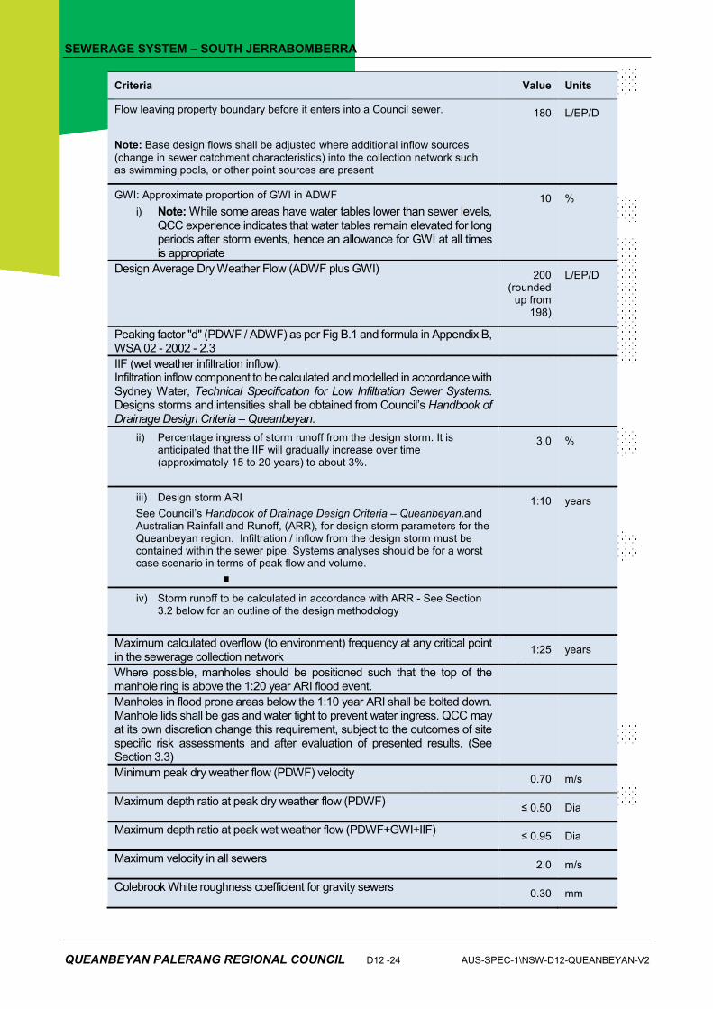
Criteria Value Units
Flow leaving property boundary before it enters into a Council sewer.
Note: Base design flows shall be adjusted where additional inflow sources
(change in sewer catchment characteristics) into the collection network such as swimming pools, or other point sources are present
180 L/EP/D
GWI: Approximate proportion of GWI in ADWF
i) Note: While some areas have water tables lower than sewer levels, QCC experience indicates that water tables remain elevated for long periods after storm events, hence an allowance for GWI at all times is appropriate
10 %
Design Average Dry Weather Flow (ADWF plus GWI) 200
(rounded up from
198)
L/EP/D
Peaking factor "d" (PDWF / ADWF) as per Fig B.1 and formula in Appendix B, WSA 02 - 2002 - 2.3
IIF (wet weather infiltration inflow). Infiltration inflow component to be calculated and modelled in accordance with Sydney Water, Technical Specification for Low Infiltration Sewer Systems. Designs storms and intensities shall be obtained from Council’s Handbook of Drainage Design Criteria – Queanbeyan.
ii) Percentage ingress of storm runoff from the design storm. It is anticipated that the IIF will gradually increase over time (approximately 15 to 20 years) to about 3%.
3.0 %
iii) Design storm ARI
See Council’s Handbook of Drainage Design Criteria – Queanbeyan.and Australian Rainfall and Runoff, (ARR), for design storm parameters for the Queanbeyan region. Infiltration / inflow from the design storm must be contained within the sewer pipe. Systems analyses should be for a worst case scenario in terms of peak flow and volume.
�
1:10 years
iv) Storm runoff to be calculated in accordance with ARR - See Section 3.2 below for an outline of the design methodology
Maximum calculated overflow (to environment) frequency at any critical point in the sewerage collection network
1:25 years
Where possible, manholes should be positioned such that the top of the manhole ring is above the 1:20 year ARI flood event.
Manholes in flood prone areas below the 1:10 year ARI shall be bolted down. Manhole lids shall be gas and water tight to prevent water ingress. QCC may at its own discretion change this requirement, subject to the outcomes of site specific risk assessments and after evaluation of presented results. (See Section 3.3)
Minimum peak dry weather flow (PDWF) velocity 0.70 m/s
Maximum depth ratio at peak dry weather flow (PDWF) ≤ 0.50 Dia
Maximum depth ratio at peak wet weather flow (PDWF+GWI+IIF) ≤ 0.95 Dia
Maximum velocity in all sewers 2.0 m/s
Colebrook White roughness coefficient for gravity sewers 0.30 mm

SEWERAGE SYSTEM – SOUTH JERRABOMBERRA
AUS-SPEC-1\NSW-D12-SOUTH JERRABOMBERRA-V2 D12 - 25 QUEANBEYAN PALERANG REGIONAL COUNCIL
Colebrook White roughness coefficient for pump pressure mains
I) Plastic, glass reinforced, and epoxy lined ductile iron pipes
II) Unlined or cement lined ductile iron pipes
0.30
0.60
mm
mm
Minimum and maximum grades and pipe deflection shall be in accordance with manufacturers’ recommendations and within the Sewerage Code of Australia Planning and Design guidelines.
Diameters of personnel entry points shall be agreed with QCC. The primary reason is to provide sufficient ingress and egress during maintenance and recovery operations.
Overflow relief gullies (ORGs) shall be leak proof (anti infiltration), allowing surcharge relief. Maintenance of the water seal shall not be achieved by water from a tap located over the gully.
LEAK TIGHT SEWERAGE SYSTEMS
QCC may consider a Leak Tight sewerage system under certain conditions.

SEWERAGE SYSTEM – SOUTH JERRABOMBERRA
QUEANBEYAN PALERANG REGIONAL COUNCIL D12 - 26 AUS-SPEC-1\NSW-D12-QUEANBEYAN-V2
Analysis and Design Methodology
The analysis of sewage collection networks should be similar to a storm drainage methodology than a conventional sewerage methodology. The approach, routs flows (ranging from steady state, inflow hydrographs to unsteady ((dynamic)) modelling for pressurised systems) through a pipe network to determine flow characteristics in the pipes and the range of inflows or inflow hydrograph to the sewage treatment plant or pump station. In summary the LISS methodology includes:
(1) For each node in the network for NEW and OLD systems (as per endorsed design life):
(i) Calculate average dry weather flow (ADWF) and peak dry weather flow (PDWF) using the algorithms in WSA 02
(i) Calculate a dry weather Ground Water Infiltration (GWI) allowance
(ii) Calculate the amount of wet weather infiltration / inflow (IIF) entering the sewerage system from the design storm based on a 1:10 year ARI design storm (see Australian Rainfall and Runoff). Design shall consider the most critical events in terms of peak flow and volume. The design shall consider the following scenarios:
a. Drought periods;
b. Periods with average rainfall;
c. Prolonged periods with above average rainfall; and
d. Climate change.
QCC shall endorse selected design ARIs and design assumptions.
(2) Rout the design flow, QD (PDWF plus GWI and IIF), at each node through the pipe network to determine the flow characteristics for each pipe length between nodes. A spread-sheet based steady state and unsteady state analysis can be used to calculate flow characteristics in pipes at PDWF and QD.
(3) Adjust the internal pipe diameters and grades for the proposed new sewage collection system until flow conditions in all pipes comply with the specified design criteria.
(4) Estimate the overflow conditions (frequency, total volume of overflow, duration of the overflow) at critical points in the sewage collection system (i.e, pump stations, treatment plant inlets, near water courses or water bodies, schools, hospitals, aged care facilities, etc) for:
(i) The proposed new system; in terms of compliance with the specified overflow design frequency.
(ii) The downstream existing networks; in terms of inflows maintaining or improving pre-existing overflow conditions in the existing system.
(5) In order to prepare an overflow management plan, QCC will need to know both the return period (probability) of an overflow event and the size of the storm that gave rise to it. Two approaches could be used as follows:
(i) Increasing the design storm ARI (duration and intensity of storms) until overflow occurs in the overall system at critical points.
(ii) Using statistical methods, create a time series of runoff events to estimate the return period (probability) of an overflow occurring in the overall system at critical points.
(6) Determine appropriate adjustments to the sewage collection system to meet the required sewage overflow design criteria:
(i) In the proposed new collection network this could include (but not limited to):
a. Increasing proposed pipe diameters and grade; and
b. Providing emergency attenuation storage.
This is to ensure that the overflow frequency at any point in the new system meets the specified criteria.
(ii) In the downstream existing receiving network this could include (but not limited to):
a. Augmentation of the existing network; and
b. Providing emergency attenuation storage.
SEWERAGE SYSTEM – SOUTH JERRABOMBERRA
AUS-SPEC-1\NSW-D12-SOUTH JERRABOMBERRA-V2 D12 - 27 QUEANBEYAN PALERANG REGIONAL COUNCIL
This is to ensure that the overflow frequency in the downstream existing network does not exceed pre-existing conditions.
(7) Provide properly designed overflow retention and primary treatment facilities at identified overflow points to facilitate actions under the QCC Sewerage Recovery Plan as follows:
(i) At critical points in the proposed new sewage collection network.
(ii) At critical points in the existing downstream system where inflows from the proposed new system exacerbate overflow conditions.
(8) As the hydraulic analysis will need to cover pipe flow conditions ranging from open channel to pressure flow, and may require dynamic extended period as well as steady state analysis, computer software may need to be used, particularly for estimating overflow conditions.
Presentation of Results
The proponent (and/or design consultant) shall present the system analyses in a report, including at least (but not limited to) the following information:
(1) Brief summary overview of the project including background, overall scope sewer catchment characteristics (size, layout, etc.), staging, scenarios modelled, modelling outcomes, etc.
(2) Population, EP, and flow projections by year and land use / development type including; household size for each dwelling type, unit per EP flow rates, schedule of lot sizes, etc to enable QCC to understand flow build up in the system.
(3) Staging of infrastructure.
(4) Summary of key modelling assumptions used including any analyses under ARR to determine wet weather infiltration inflow and sewage overflow conditions.
(5) Input data to the model either in native format (if software such as SWMM is used) or Excel Spread Sheet including a schematic (node and pipe numbering) of the network model.
(6) Output data from the model either in native format (if software such as SWMM is used) or Excel Spread Sheet.
(7) Sketches and maps showing the layout of the complete proposed new sewage collection system including a clear indication of system staging.
(8) Sketches and maps showing any proposed augmentations to the downstream existing system required to maintain or improve pre-existing sewage overflow conditions.
(9) Sketches and maps showing provision for overflow management facilities at critical points where necessary.
(10) Sketches and maps showing proposed locations of sewer flow gauging chambers including recommended gauging and remote monitoring equipment.
(11) Sketches and maps indicating flood lines and levels including output data tables from modelling software.
(12) Geotechnical report describing findings of gexdotechnical results such as (but not limited to):
a. Excavatability of soil;
b. Soil profile and classification;
c. Whether ground water or moist conditions was encountered; and
d. Permeability of native soil.