sewage treatment – technologies - public health … st… · · 2015-09-08max 50 50 6 5 total...
TRANSCRIPT

SEWAGE TREATMENT –
TECHNOLOGIESTECHNOLOGIES

Types of contaminants in SewageTypes of contaminants in Sewage
ORGANIC INORGANIC
• Sugar
• Milk
Suspended Dissolved SuspendedDissolved• Vegetable matter
• Food residue
• Plastic bags
• Cans
• Fiber
• clothes
• Salt
Biological treatment Primary treatment

Sl. No Contaminant Source Environmental
significance
1 Suspended solids Domestic use,
industrial wastes
Cause sludge deposits
and anaerobic condition
in aquatic environment
Important Waste Water Contaminants
in aquatic environment
2 Biodegradable
organic
Domestic use ,
industrial wastes
Cause biological
degradation
3 Pathogens Domestic water Transmit communicable
disease
4 nutrients Domestic and
industrial waste
Cause eutrophication
5 Refractory organics Industrial waste Cause taste and odour
problems

Pollutants in sewage
•BOD(Bio Chemical Oxygen demand)
•COD(Chemical Oxygen demand)•COD(Chemical Oxygen demand)
•TSS(Total Suspended Solids)
•PH

BOD(Biochemical Oxygen demand)
The BOD is an important measure of water quality .It is measure of the amount of
oxygen needed by bacteria and other organisms to oxidize the organic matter
present in a water sample over a period of 5 days at 20 degree C.
COD (Chemical Oxygen Demand)
�COD Measures all organic carbon with the exception of some aeromatics
(BENZENE,TOLUENE,PHENOL etc.) which are not completely oxidized in the
reaction.
� COD is a chemical oxidation reaction
�Ammonia will not be oxidized.
Total Suspended Solids
�Total suspended solids(TSS) include all particles suspended in water which will
pass through a filter.

�As levels of TSS increase, a water body begins to lose its ability to support a
diversity of aquatic life.
�Suspended solids absorb heat from sunlight, which increases water
temperature and subsequently decreases levels of dissolved oxygen(warmer
water holds less oxygen than cooler water)

STANDARDS OF RAW/ TREATED
SEWAGESr.
No.
Parameter Public
SewersTreated Effluent
After secondary
treatment
After tertiary
treatment
1 pH value 5.5 – 9.0 5.5 – 9.0 5.5-9.0
2 Oil and grease, mg/l max 20 10 2
3 Total residual chlorine, mg/l max – 1.0 0.5
4 Ammonical nitrogen (as N),mg/l,
max
50 50 6
5 Total kjeldahl nitrogen (as N);mg/l,
max. mg/l, max
– 100 16
6 Free ammonia (as NH3), mg/l, max – 5.0 6
7 Biochemical oxygen demand (3
days at 27°C), mg/l, max
350 30 <5
8 Chemical oxygen demand, mg/l,
max
– 250 50
9 Suspended solids mg/l, max 600 100 8.00

Components of Sewage Treatment
Plants
• Pumping of Sewage
• Primary Treatment
• Secondary treatment
• Tertiary Treatment• Tertiary Treatment

Typical Flow Diagram of Sewage Treatment PlantTypical Flow Diagram of Sewage Treatment Plant
FINE
SCREENIN
G GRIT
REMOVAL
GRITRAW
SEWAGE INLET CHAMBERRAW SEWAGE
PUMPING
COARSE
SCREENIN
GRAW SEWAGE PUMPING STATION PRIMARY TREATMENT
AERATION TANK
SECONDARY
CLARIFIER
TREATED
WATER
DISINFECTION
CHLORINE
SLUDGE
RECIRCULATION
AIR BLOWER
RAW SEWAGE PUMPING STATION PRIMARY TREATMENT
SECONDARY TREATMENT
TERTIARY TREATMENT
SLUDGE
SUMPCENTRIFUGE
SLUDGE
SLUDGE DEWATERING SURPLUS SLUDGE
CENTRA
TE
TO AT

Pumping StationPumping Station
• Receiving Chamber
• Coarse Screening
• Wet Well (Raw Sewage
Sump)
• Pump House
• Raw Sewage Pumps
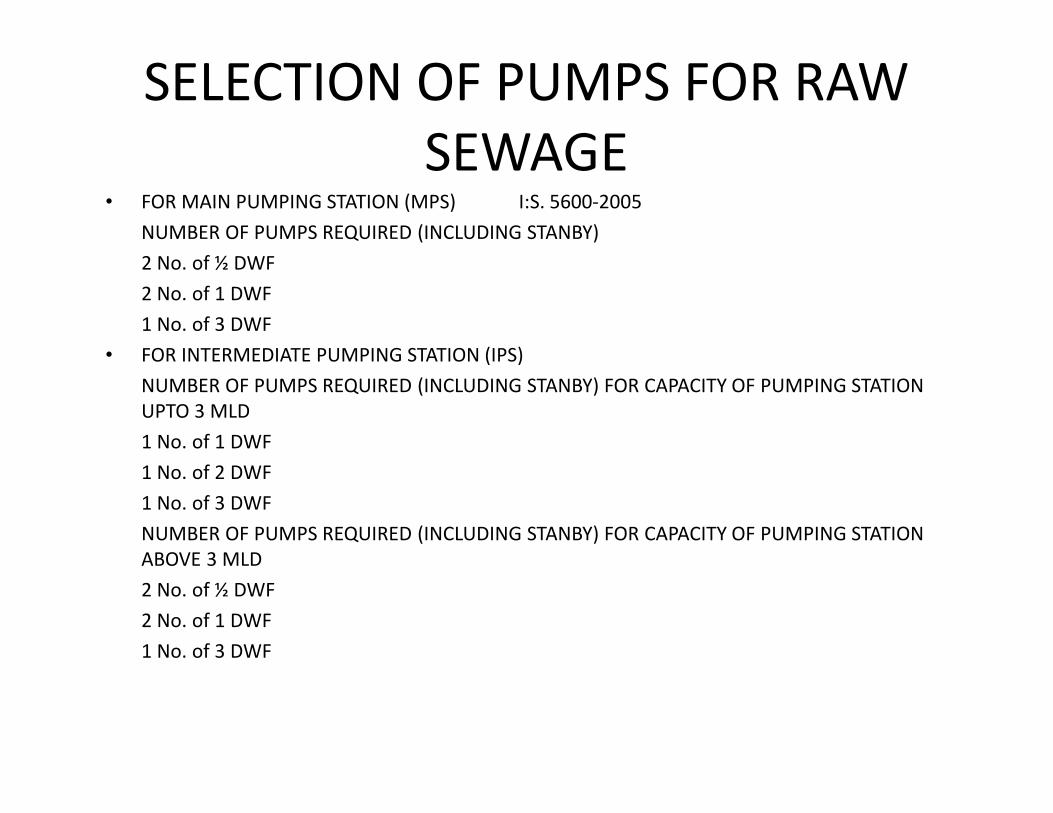
SELECTION OF PUMPS FOR RAW
SEWAGE• FOR MAIN PUMPING STATION (MPS) I:S. 5600-2005
NUMBER OF PUMPS REQUIRED (INCLUDING STANBY)
2 No. of ½ DWF
2 No. of 1 DWF
1 No. of 3 DWF
• FOR INTERMEDIATE PUMPING STATION (IPS)
NUMBER OF PUMPS REQUIRED (INCLUDING STANBY) FOR CAPACITY OF PUMPING STATION
UPTO 3 MLDUPTO 3 MLD
1 No. of 1 DWF
1 No. of 2 DWF
1 No. of 3 DWF
NUMBER OF PUMPS REQUIRED (INCLUDING STANBY) FOR CAPACITY OF PUMPING STATION
ABOVE 3 MLD
2 No. of ½ DWF
2 No. of 1 DWF
1 No. of 3 DWF

VELOCITY CONSIDERATION IN DESIGN
OF PUMPING (RISING) MAIN FOR
PUMPING SEWAGE
• The size of Rising main should be designed after taking into
consideration that:
Maximum velocity at peak flow should not exceed 2.7 m/s.
Minimum velocity at low flows should not be less than 1 m/s.
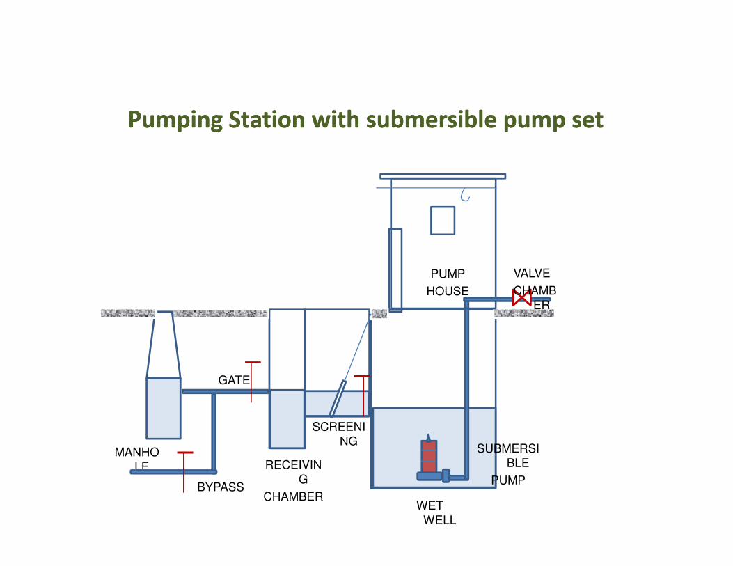
Pumping Station with submersible pump setPumping Station with submersible pump set
PUMP VALVE
MANHO
LE
BYPASS
GATE
RECEIVIN
G
CHAMBER
SCREENI
NG
WET
WELL
HOUSE
SUBMERSI
BLE
PUMP
CHAMB
ER

Pumping Station with Centrifugal Pump setPumping Station with Centrifugal Pump set
PUMP
HOUSE
MANHO
LE
BYPASS
GATE
RECEIVIN
G
CHAMBER
SCREENI
NG
WET
WELL
HOUSE
SUBMERSI
BLE
PUMP
CENTRIFUGAL
HORIZONTAL
PUMPS

Primary TreatmentPrimary Treatment
• Fine Screening
• Grit Removal
• Primary Clarification

• Objective : Removal of coarse solids
• Types of screens : Fine / medium / coarse
• Cleaning of screens : Manual / mechanical
Screening
• Cleaning of screens : Manual / mechanical
• Benefits : Protection of pumps
• Coarse Screening : 20mm clear spacing in bars
• Fine screening : 6mm clear spacing in bars

Screening
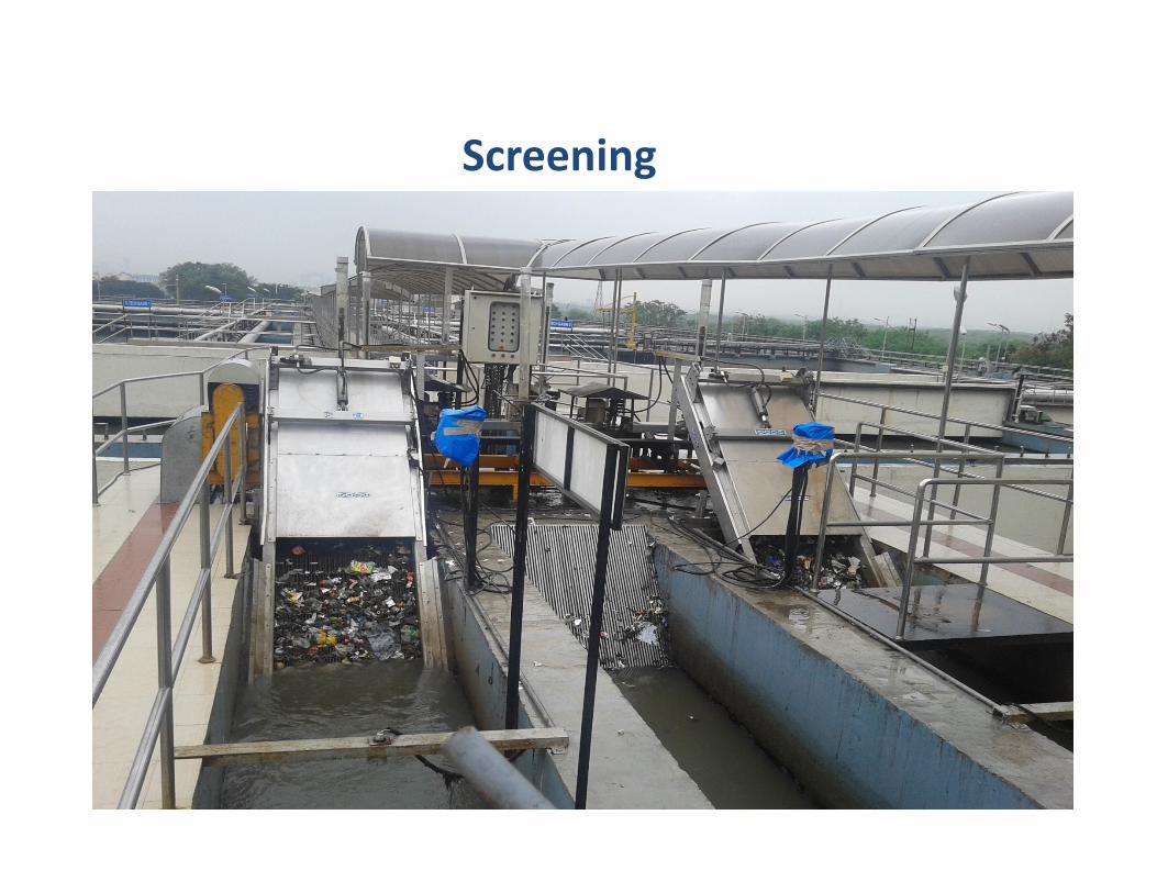
Screening

ARC BAR SCREEN
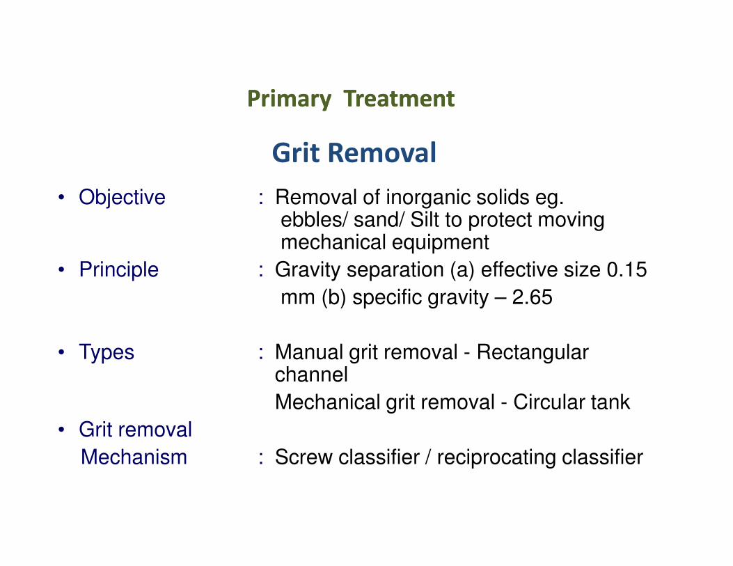
Grit Removal
• Objective : Removal of inorganic solids eg.ebbles/ sand/ Silt to protect moving mechanical equipment
• Principle : Gravity separation (a) effective size 0.15
Primary Treatment Primary Treatment
mm (b) specific gravity – 2.65
• Types : Manual grit removal - Rectangular channel
Mechanical grit removal - Circular tank
• Grit removal
Mechanism : Screw classifier / reciprocating classifier
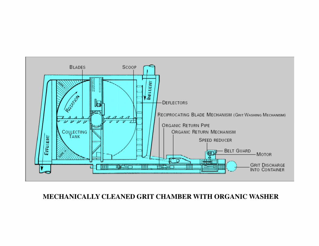
MECHANICALLY CLEANED GRIT CHAMBER WITH ORGANIC WASHER

Grit Removal

GRIT CHAMBER WITH CLASSIFIER & WASHER
Secondary TreatmentSecondary Treatment
Biological treatment

Sewage Treatment
Method of Treatment-Aerobic, Anaerobic.
• Aerobic-Sewage treatment in the presence of
Oxygen-MBBR, SBR-where aerators/blowers areOxygen-MBBR, SBR-where aerators/blowers are
installed-generally no smell during treatment.
• Anaerobic-Sewage treatment in the absence of
Oxygen-UASB-No aerators/blowers are required-foul
smell during treatment.

VARIOUS SEWAGE TREATMENT TECHNOLOGIES
• Activated Sludge Process (ASP)
• Upflow Anaerobic Sludge Blanket Reactor
(UASB)
• Moving Bed Biofilm Reactor (MBBR)• Moving Bed Biofilm Reactor (MBBR)
• Sequential Batch Reactor (SBR)
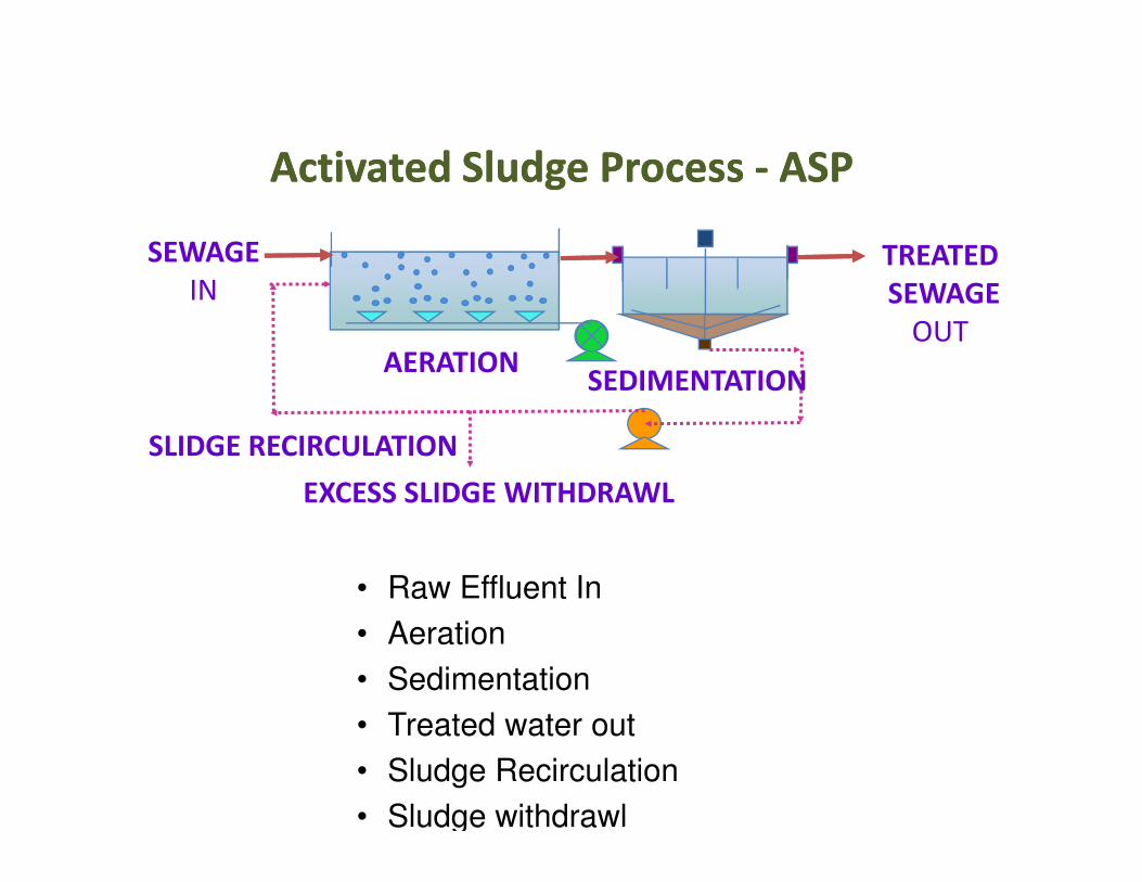
AERATIONSEDIMENTATION
SLIDGE RECIRCULATION
TREATED
SEWAGE
OUT
SEWAGE
IN
Activated Sludge Process Activated Sludge Process -- ASPASP
EXCESS SLIDGE WITHDRAWL
SLIDGE RECIRCULATION
• Raw Effluent In
• Aeration
• Sedimentation
• Treated water out
• Sludge Recirculation
• Sludge withdrawl
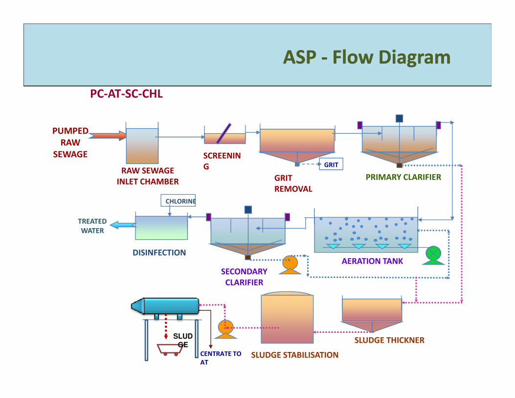
ASP ASP -- Flow DiagramFlow Diagram
CHLORINE
SCREENIN
G
GRIT
REMOVAL
GRIT
PUMPED
RAW
SEWAGE
PRIMARY CLARIFIERRAW SEWAGE
INLET CHAMBER
PC-AT-SC-CHL
AERATION TANK
SECONDARY
CLARIFIER
TREATED
WATER
DISINFECTION
CHLORINE
CENTRATE TO
ATSLUDGE STABILISATION
SLUDGE THICKNERSLUD
GE

Activated Sludge Process (ASP) Technology
• An activated sludge plant essentially consists of the following:
1) Aeration tank containing micro organisms in suspension in which
reaction takes place.
2) Activated sludge recirculation system.
3) Excess sludge wasting and disposal facilities.
4) Aeration systems to transfer oxygen4) Aeration systems to transfer oxygen
5) Secondary sedimentation tank to separate and thicken activated sludge.

ASP
• Advantages
– Can sustain seasonal variation
– Less land requirement than UASB
• Disadvantages
– High energy consumption
– Foaming, particularly in winter season, may adversely – Foaming, particularly in winter season, may adversely
affect the oxygen transfer, and hence performance
– Requires elaborate sludge digestion /drying/disposal
arrangement
– More land requirement than SBR & MBBR
– Nitrogen and Phosphorous removal requires additional
anoxic tank and > 3 times internal recirculation

ASPASP

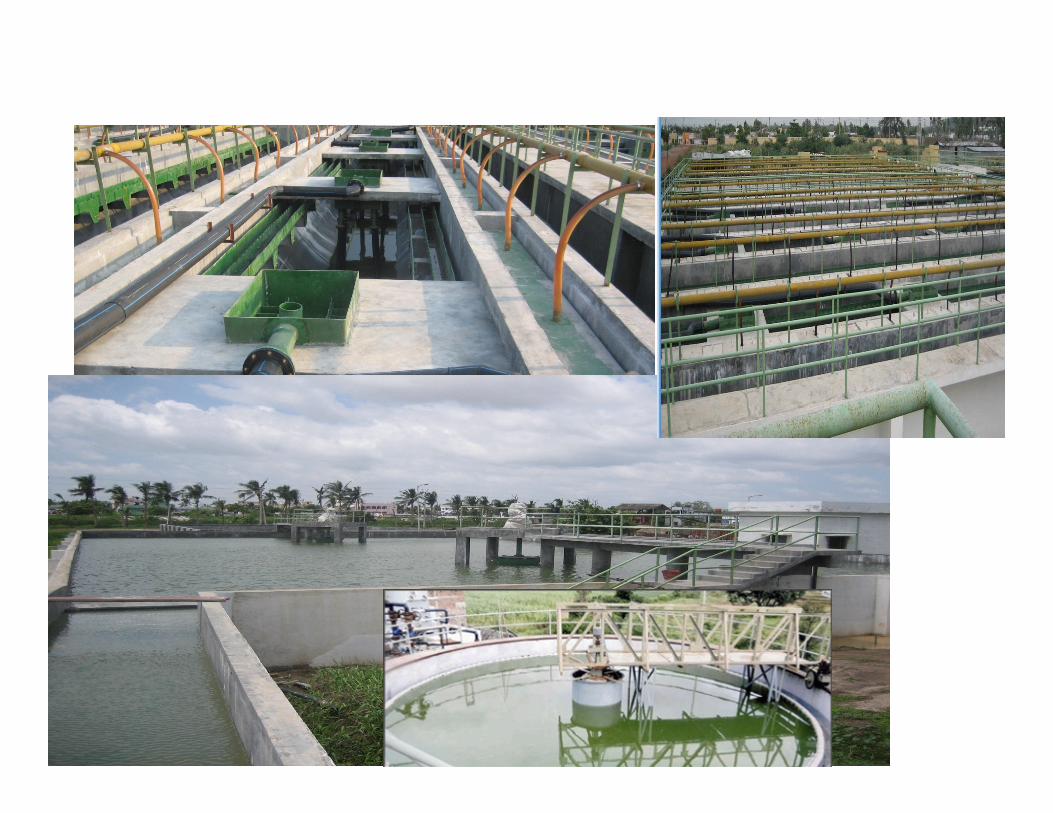
Upflow Anaerobic Sludge Blanket Reactor
(UASB)
• The Up flow Anaerobic Sludge Blanket reactor (UASB) maintains ahigh concentration of biomass through formation of highly settleablemicrobial aggregates. The sewage flows upwards through a layer ofsludge.
• The sludge in the UASB is tested for pH, volatile fatty acids (VFA),alkalinity, COD and SS. If the pH reduces while VFA increases, thesewage should not be allowed into the UASB until the pH and VFAsewage should not be allowed into the UASB until the pH and VFAstabilise.
• The reactor may need to be emptied completely once in five years,while any floating material (scum) accumulated inside the gascollector channels may have to be removed every two years toensure free flow of gas.
• All V-notches must be cleaned in order to maintain the uniformwithdrawal of UASB effluent coming out of each V-notch. Theirregular flow from each V-notch results in the escape of more solidswashout. Similarly, blocking of the V-notches of the effluent gutterswill lead to uneven distribution of sewage in the reactor.

Up Up –– Flow Anaerobic Sludge Blanket Rector (UASB) Flow Anaerobic Sludge Blanket Rector (UASB)
Flow DiagramFlow Diagram
SCREENIN
G
GRIT
GRIT
RAW
SEWAGE
RAW SEWAGE
INLET CHAMBER
ELECTRICIT
Y
UASB-AT-SC-CHL
AERATION TANK
SECONDARY
CLARIFIER
TREATED
WATER
DISINFECTION
CHLORINE
GRIT
REMOVALINLET CHAMBER
GAS HOLDER
SLUDGE DEWATERING
SYSTEM
UASBGAS
ENGINE

UASB
Advantages
• Requires less power than aerobic processes
• Biogas generated can be used as fuel or
electricity.
Disadvantages Disadvantages
• UASB alone does not treat the sewage to
desirable limits, therefore downstream aerobic
treatment is compulsory
• Requires very large space due to post treatment
• Recovery of biogas is not sufficient to produce
substantial electricity in case of municipal
sewage.
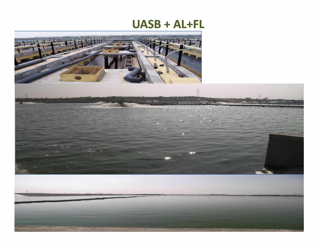
UASB + AL+FLUASB + AL+FL

MOVING BED BIO REACTOR (MBBR) PROCESS
• Moving Bed Bio Reactor (MBBR) process is based on the bio-film of
organisims developed on carrier elements.
• This media is floating in the Aeration tank and kept floating by air
from diffusers which are placed at the bottom of tank.
• The process is intended to enhance the activated sludge process by• The process is intended to enhance the activated sludge process by
providing greater biomass in aeration tank and thus by reducing
volume of the tank
• After aeration tank sedimentation tank is provided for settlement of
sloughed biomass
• Clear water clarifier overflows from weir and is further subjected to
disinfection.

Moving Bed Bio Rector (MBBR) Moving Bed Bio Rector (MBBR) -- Flow DiagramFlow Diagram
CHLORINE
SCREENIN
G
GRIT
REMOVAL
GRIT
PUMPED
RAW
SEWAGE
RAW SEWAGE
INLET CHAMBER
MBBR-SC-CHL
CARRIER MEDIA
AERATION TANK (MBBR)
SECONDARY
CLARIFIER
TREATED
WATER
DISINFECTION
CHLORINE
SLUDGE
DEWATERINGFILTRATE TO AERATION TANK
CARRIER MEDIA

MBBR MBBR
Quantity of BIO Media
• Check Design approved by SE to see quantity
of BIO media 1m3 per 7.5 Kg BOD considering
surface area of media 250 m2/m3
• The specifications are given in agreement. • The specifications are given in agreement.
Specific gravity 0.96.
• Make by Kaldnes biofilm carrier

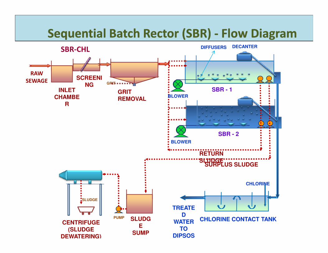
SEQUENTIAL BATCH REACTOR (SBR) PROCESS
• Sequential Batch Reactor is true batch process where fill, aeration,
settle and decant steps are carried out in sequence of batches in a
single basin.
• Screened, de-gritted sewage is fed into the SBR Basins for biological
treatment to remove BOD, COD, Suspended Solids, Biological
Nitrogen and Phosphorous.Nitrogen and Phosphorous.
• SBR process shall work on batch mode in single step.
• It performs biological organic removal, nitrification, de-nitrification
and biological phosphorous removal.
SCREENING
GRIT REMOVAL
GRIT
INLET CHAMBE
R
RAW
SEWAGE
DECANTERDIFFUSERS
BLOWER
SBR - 1
Sequential Batch Rector (SBR) Sequential Batch Rector (SBR) -- Flow DiagramFlow DiagramSBR-CHL
TREATED
WATER TO
DIPSOS
SBR - 2
SLUDGE
SUMP
CHLORINE CONTACT TANKCENTRIFUGE
(SLUDGE DEWATERING)
RETURN SLUDGE
SURPLUS SLUDGE
BLOWER
CHLORINE
SLUDGE
PUMP

RAW
SEWAGE
PUMPING
STATION
SBR BASIN
DE
CA
NT
ER
S
Modular Design
SBR BASIN
INLET
CHAMBERSCREENS
GRIT
REMOVAL
TANKS
SBR BASIN
SLUDGE
HANDLING
SYSTEM
FINAL DISCHARGE
SELECTORS
DE
CA
NT
ER
S
RAS/SAS PUMPS
SBR BASIN
CHLORINATION

SBR Process

SBR / Cyclic Activated Sludge Process• Better Quality Effluent: 98 % BOD removal efficiency. Sewage can be
treated to reuse/recycle quality of TSS < 10 mg/l, COD < 100 ppm, BOD <
10 ppm, TN < 10 ppm, TP < 2 ppm in a single stage of treatment using
Batch process.
• Bio-nutrient removal (BNR) : N & P removal
• Secondary clarifier not required, less foot print area
• Flexibility for efficient removal of BOD, TSS, N& P under all loading • Flexibility for efficient removal of BOD, TSS, N& P under all loading
conditions.
• Automatically controlled by PLC . Based on process requirement, the
aeration facility is optimized based on DO levels and by varying operating
frequency of the blowers. Less power consumption.
.

SBR / Cyclic Activated Sludge ProcessAdvantages
• Controls growth of filamentous bacteria and avoids bulking of
sludge.
• Provides stabilised sludge.
• Process with primary clarifier can generate power
• Allows for easy modular expansion for population growth• Allows for easy modular expansion for population growth
• Disadvantages
• Compared to the conventional ASP / MBBR /UASB, a higher
level of sophistication and maintenance is associated due to
automation
.

SBR gives high performance
with Nutrient removal
BOD < 5 ppm
TSS < 10 ppmNH4-N< 1 ppm
TP < 1 ppm

Fully Automatic PLC operatedFully Automatic PLC operated

Plant Aesthetics


Sludge Handling – Sludge Drying Beds
� Objective : Dewatering of sludge
� Important Features
- Conventional method of sludge drying
- No power requirement
- Substantial area is required
- Difficult to operate in monsoon- Difficult to operate in monsoon
- Labour intensive
- Manual scrapping and loading of dried sludge

SLUDGE DRYING BED
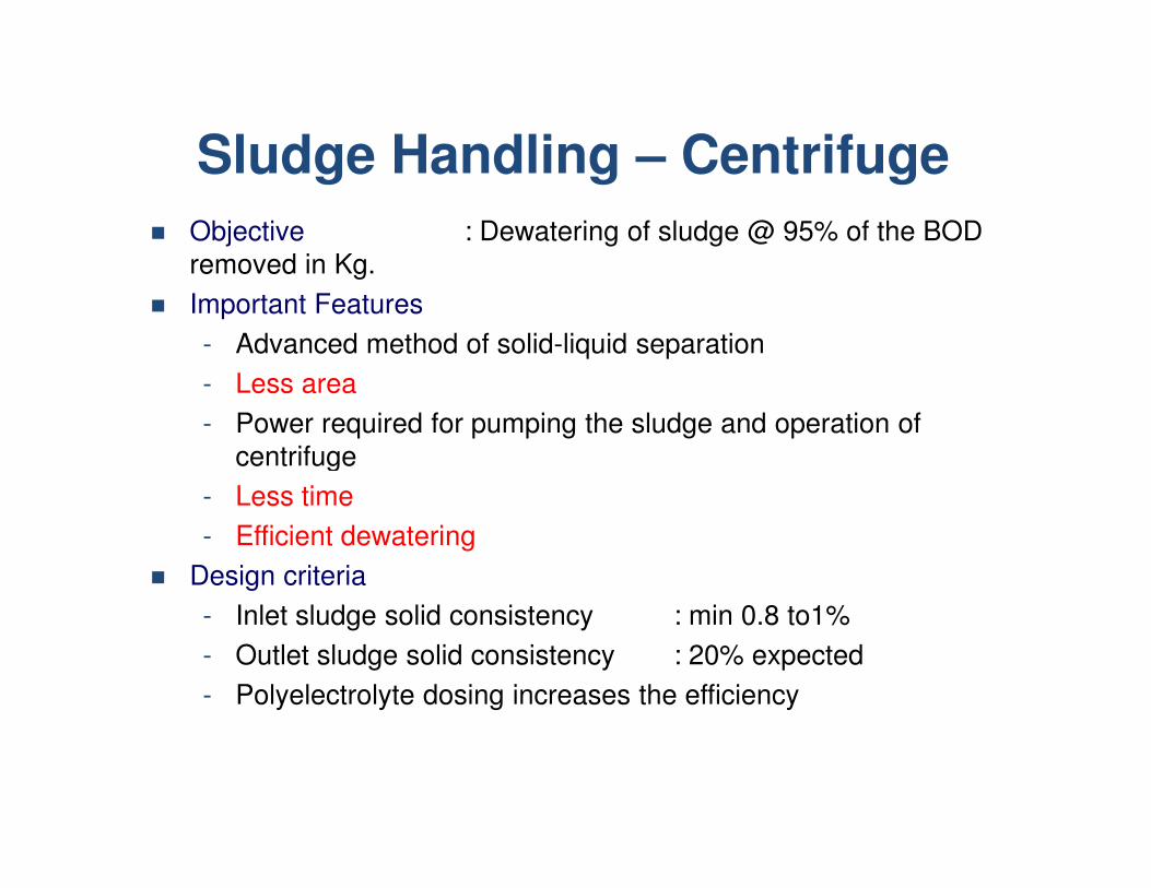
Sludge Handling – Centrifuge
� Objective : Dewatering of sludge @ 95% of the BOD
removed in Kg.
� Important Features
- Advanced method of solid-liquid separation
- Less area
- Power required for pumping the sludge and operation of
centrifuge centrifuge
- Less time
- Efficient dewatering
� Design criteria
- Inlet sludge solid consistency : min 0.8 to1%
- Outlet sludge solid consistency : 20% expected
- Polyelectrolyte dosing increases the efficiency

Centrifuge

BELT PRESS

SOLID BOWL CENTRIFUGE

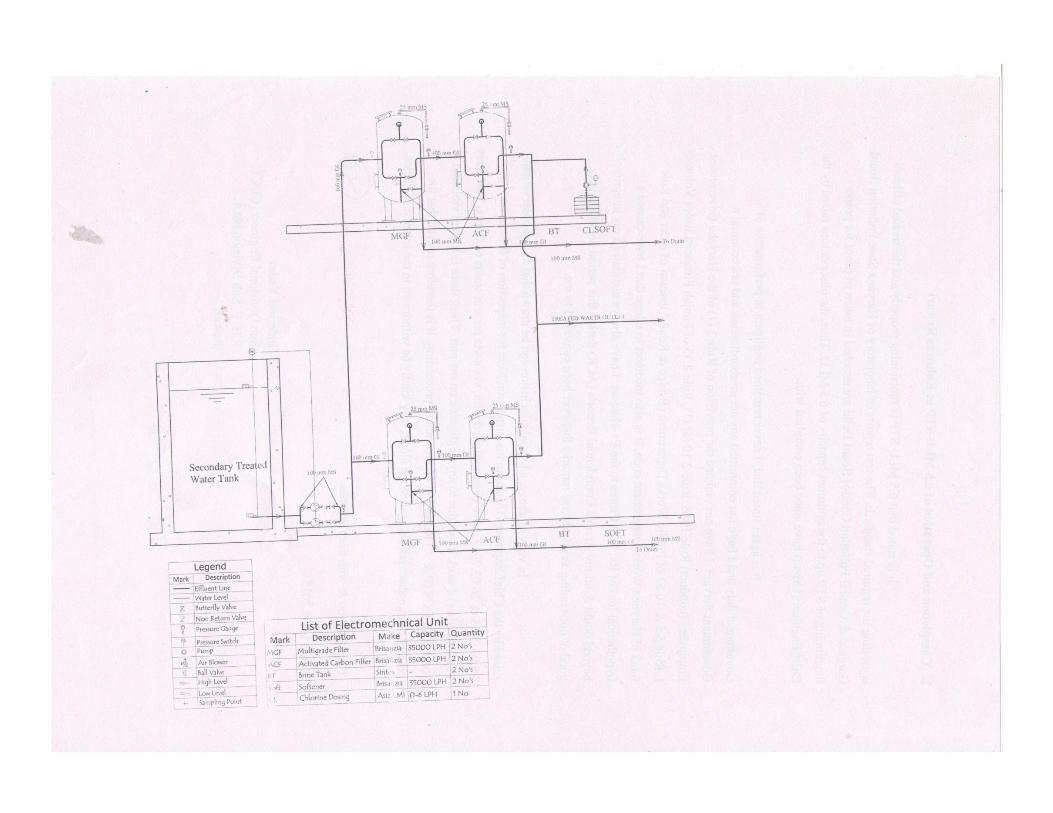
Tertiary TreatmentTertiary Treatment
It is supplementary to primary and secondary treatment for the purpose of
removing the residual organic and inorganic substances for reuse of effluent
for the purposes of cooling systems, boiler feed, process water etc.
Treated effluent
from secondary Multi Grade Filter Activated Carbon from secondary
treatmentMulti Grade Filter Activated Carbon
Filter
ChlorinationReuse
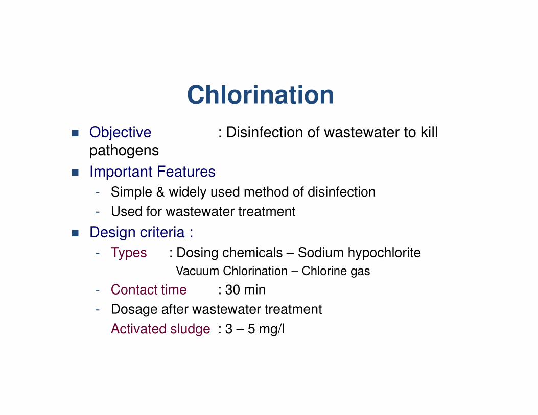
Chlorination
� Objective : Disinfection of wastewater to kill
pathogens
� Important Features
- Simple & widely used method of disinfection
- Used for wastewater treatment- Used for wastewater treatment
� Design criteria :
- Types : Dosing chemicals – Sodium hypochlorite
Vacuum Chlorination – Chlorine gas
- Contact time : 30 min
- Dosage after wastewater treatment
Activated sludge : 3 – 5 mg/l

Chlorine Contact Tank
Chlorine is a Hazardous chemical requiring adequate safety while handling
1. Chlorine leak detector
2. Chlorine absorption system
3. Personal safety eqpt .– mask etc.
4. Safety shower4. Safety shower
5. Statutory records

Other options for disinfection
• Chlorine produces carcinogenic disinfection byproducts that are harmful to
human and aquatic life.
• It is banned in developed countries.
• Still used in India as it is cheap
• Other options are;
• Ultra Violet (UV) - like Aquaguard
• Ozone