sewage catalogue pumps stations and solids separation · pdf filepumps stations and solids...
TRANSCRIPT

Pumps stationsSubmersible sewage pumps with maceratorsSolids separation systemsAccessories
Sewage catalogue
Pumps stations and solidsseparation systems
Catalogue C 3.1 - 50 Hz - 2010 C3.1
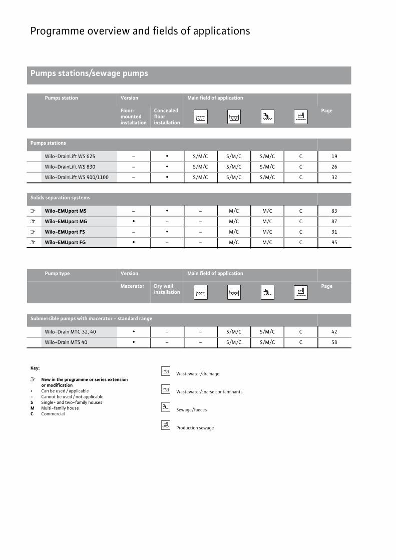
Programme overview and fields of applications
Pumps stations/sewage pumps
Pumps station Version Main field of application
Floor-mounted installation
Concealed floor installation
Page
Pumps stations
Wilo-DrainLift WS 625 – • S / M / C S / M / C S / M / C C 19
Wilo-DrainLift WS 830 – • S / M / C S / M / C S / M / C C 26
Wilo-DrainLift WS 900/1100 – • S / M / C S / M / C S / M / C C 32
Solids separation systems
� Wilo-EMUport MS – • – M / C M / C C 83
� Wilo-EMUport MG • – – M / C M / C C 87
� Wilo-EMUport FS – • – M / C M / C C 91
� Wilo-EMUport FG • – – M / C M / C C 95
Pump type Version Main field of application
Macerator Dry well installation
Page
Submersible pumps with macerator - standard range
Wilo-Drain MTC 32, 40 • – – S / M / C S / M / C C 42
Wilo-Drain MTS 40 • – – S / M / C S / M / C C 58
Key:
� New in the programme or series extensionor modification
• Can be used / applicable- Cannot be used / not applicableS Single- and two-family housesM Multi-family houseC Commercial
Wastewater / drainage
Wastewater/coarse contaminants
Sewage / faeces
Production sewage

3
Contents
Wilo catalogue C 3.1 - 50 Hz – Pumps stations and solids separation systems
Pres
sure
dra
inag
eSo
lids
sepa
ratio
n sy
stem
Acce
ssor
ies
none
Non
e
General notes and abbreviations 4
Planning guide 6
Pressure drainage 14
Wilo-DrainLift WS 625 19Wilo-DrainLift WS 830 26Wilo-DrainLift WS 900/1100 32Wilo-Drain MTC 42Wilo-Drain MTS 58
Solids separation systems 72
Planning guide 72Wilo-EMUport FTS MS 83Wilo-EMUport FTS MG 87Wilo-EMUport FTS FS 91Wilo-EMUport FTS FG 95
Accessories 98
Recommended accessories 98Equipment/function 101Electrical accessories 104

4 Subject to change 09/2009 WILO SE
General notes and abbreviations
General notes and abbreviations Subject to change 09/2009 WILO SE Wilo catalogue C 3.1 - 50 Hz – Pumps stations and solids separation system
Abbreviation Meaning1~ 1-phase alternating current
3~ 3-phase current
-A Float switch attached
D Direct activation
DI Leakage detection
Di Inside diameter
Di min. Minimum inside diameter
DM Three-phase motor, 3~
DN Nominal diameter of the flange connection
EBM Individual run signal
EM Single-phase motor, 1~
ESM Individual fault signal
GRD/GLRD Mechanical seal
F Thrust in newtons (N) (for submersible mixers)
H Delivery head
HA Suction head; inlet floor to ground level
HB Installation depth to inlet floor
HN Site altitude above MSL (mean sea level)
HG Groundwater level to MSL (mean sea level)
IA Starting current
IN Nominal current; current at P2Inst. Installation: H = horizontal, V = vertical
LBSupply availability (L = stock article, C = available in 2 weeks, K = available in 4 weeks, A = available on request)
P1Power consumption (power supplied from the network)
P1.1 Power consumption at the duty point
PN = P2 Nominal motor power
PN Pressure class in bar (e.g. PN10 = suitable up to 10 bar)
PTC Positive temperature coefficient (PTC ther-mistor sensor)
PT 100 Platinum temperature sensor with a resist-ance value of 100 � at 0 °C
Q (= �) Volume flow
-S Float switch attached
SBM Run signal or collective run signal
SSM Fault signal or collective fault signal
WSKThermal winding contacts (in motor for mon-itoring the winding temperature, full motor protection through additional tripping unit)
Y/� Star-delta switching
�Operating mode of double pumps: Individual operation of the respective duty pump
�Operating mode of double pumps: Parallel operation of both pumps
�Number of poles of electric motors: 2-pole motor = approx. 2900 rpm at 50 Hz
�Number of poles of electric motors: 4-pole motor = approx. 1450 rpm at 50 Hz
�Number of poles of electric motors: 6-pole motor = approx. 950 rpm at 50 Hz
Abbreviation Meaning

5
General notes and abbreviations
Wilo catalogue C 3.1 - 50 Hz – Pumps stations and solids separation system
Wear and tearPumps or parts of pumps are subject to wear in accordance with state-of-the-art technology (DIN 31051/DIN-EN 13306). This wear may vary depending on operating parameters (temperature, pressure, speed, water conditions) and the installation/usage situation and may result in the malfunction or failure at different times of the afore-mentioned products/components, including their electrical/electron-ic circuitry.Wearing parts are all components subject to rotary or dynamic stress, including electronic components under tension, in particular:
• Seals (including mechanical seals), seal rings• Stuffing boxes • Bearings and shafts• Impellers and pump components• Wear rings and counter rings• Stationary wear rings / wear plates• Macerator • Capacitors• Relays / contactors / switches• Electronic circuits, semiconductor components, etc.
Pumps and continuous-flow machines (like submersible mixers and recirculation pumps), as well as their components with coatings (cat-aphoresis coating, 2K- or Ceram-coating) are subject to constant wear due to the abrasive fluid contents. For this reason the coating is also among the wearing parts of these units.
We do not accept any liability for faults or defects arising from natu-ral wear and tear.
Wilo – General Terms of Delivery and ServiceThe latest version of our General Terms of Delivery and Service can be found on the Internet atwww.wilo.com
Material Meaning AISI1.0570 Steel S355J2G3 A106
1.4021 Chromium steel X20Cr13 420
1.4057 Chromium steel X17CrNi16-2 431
1.4112 Chromium steel X90CrMoV18 440B
1.4122 Chromium steel X39CrMo17-1 –
1.4301 Chromium-nickel steel X5CrNi18-10 304
1.4305 Chromium-nickel steel X8CrNiS18-9 303
1.4306 Chromium-nickel steel X2CrNi19-11 304L
1.4308 Chromium-nickel steel GX5CrNi19-10 304 CF8
1.4401 Chromium-nickel-molybdenum steel X5CrNiMo17-12-2 316
1.4404 Chromium-nickel-molybdenum steel X2CrNiMo17-12-2 316L
1.4408 Chromium-nickel-molybdenum steel GX5CrNiMo19-11-2 316
1.4460 Chromium-nickel-molybdenum steel X3CrNiMo 27-5-2 329
1.4462 Chromium-nickel-molybdenum steel X2CrNiMoN22-5-3 329 (2205)
1.4470 Chromium-nickel-molybdenum steel GX2CrNiMoN22-5-3 329
1.4517Chromium-nickel-molybdenum steel with copper addition GX2CrNiMoCuN25-6-3-3
329
1.4528 Blade steel X105CrCoMo182 440B+Co
1.4541 Chromium-nickel steel with titanium addition X6CrNiTi18-10 321
1.4542Chromium-nickel steel with copper and niobium additions X5CrNiCuNb16-4
630
1.4571 Chromium-nickel steel with titanium addition X6CrNiMoTi17-12-2 316Ti
1.4581Chromium-nickel-molybdenum steel with niobium addition GX5CrNiMoNb19-11-2
316 / 316Nb
Abrasite Chilled cast iron material for use in strongly abrasive fluids –
ABS Acrylic butadiene styrene –
Al Light metal material (aluminium) –
Al-oxide Aluminium oxide –
C Carbon –
CeramCoating with very high adhesive strength for long-lasting corrosion protection
–
Composite High-strength plastic material –
EN-GJL
Grey cast iron (cast iron with lamellar graphite): the use of grey cast iron (EN-GJL-… and EN-GJS-…) in domes-tic water systems is governed by the Drinking Water Directive 98/83/EC and applicable recognised technical rules and standards.
–
EN-GJL 200 Grey cast iron GG20 –
EN-GJL 250 Grey cast iron GG25 –
EN-GJS
Grey cast iron (cast iron with spheroi-dal graphite, also called spheroidal cast iron): the use of grey cast iron (EN-GJL-… and EN-GJS-…) in domes-tic water systems is governed by the Drinking Water Directive 98/83/EC and applicable recognised technical rules and standards.
–
EN-GJS-500-7 Grey cast iron GGG50 –
G-Al Si12 Die-cast aluminium –
GfK Fibreglass plastic –
GG See EN-GJL –
GGG See EN-GJS –
Inox Stainless steel –
PA 30GF See Composite –
PE-HD High-density polyethylene –
PP-GF30 Polypropylene, reinforced with 30% fibreglass –
PUR Polyurethane –
SiC Silicon carbide –
St Steel –
St.vz. Galvanised steel –
V2A Material group, e.g. 1.4301, 1.4306 –
V4A Material group, e.g. 1.4404, 1.4571 –
Material Meaning AISI

6 Subject to change 09/2009 WILO SE
Planning guidePumps stations
Planning guide Pumps stations Subject to change 09/2009 WILO SE Wilo catalogue C 3.1 - 50 Hz – Pumps stations and solids separation systemGeneral information:
• Backflow fittings and slide valves are to be generally placed high up in the sump in the pressure pipe since deposits are avoided this way and the fittings are easily accessible for maintenance, cleaning and in-spection.
• Check valves are to be generally provided for maintenance and repair work. These are sometimes required by the standards.
• Pressure pipes are to be dimensioned according to the parameters specified in the relevant standards, e.g. flow rates and pressure stage.
• The pump sump is to be designed as small as possible around the pump.
• At the inlet of the sump, strong surge currents on the pump and components of the level sensors are to be avoided.
• During the building phase, a foundation or earthing strip is to be pro-vided for potential equalisation.
• If the outlet of the pressure pipe lies underneath the suction port of the pump, a ventilator, e.g. vacuum interrupter (accessory) is to be installed in the common pressure pipe to avoid the pump sump being sucked out up to underneath the suction port.
Double-pump pumps station
95
8
6
7 4
3
2
1
6
7
4
89
1 Foot elbow
2 Non-return valve
3 Gate valve
4 Y-piece (Y-pipe)
5 Guide pipe
6 Inlet
7 Pressure outlet
8 Cable conduit
9 Ventilation pipe
7
Planning guidePumps stations
Wilo catalogue C 3.1 - 50 Hz – Pumps stations and solids separation system
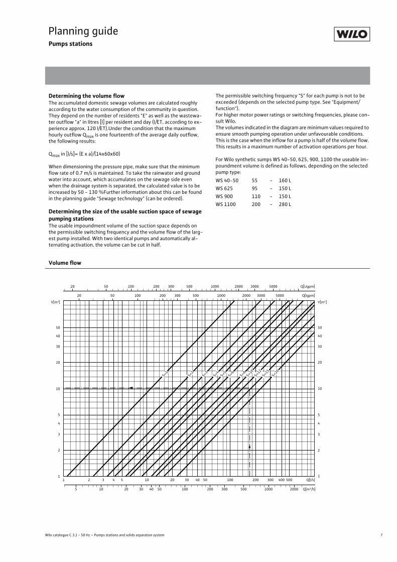
Determining the volume flowThe accumulated domestic sewage volumes are calculated roughly according to the water consumption of the community in question. They depend on the number of residents "E" as well as the wastewa-ter outflow "a" in litres [l] per resident and day (l/ET, according to ex-perience approx. 120 l/ET).Under the condition that the maximum hourly outflow Qmax is one fourteenth of the average daily outflow, the following results:
Qmax in [l/s]= (E x a)/(14x60x60)
When dimensioning the pressure pipe, make sure that the minimum flow rate of 0.7 m/s is maintained. To take the rainwater and ground water into account, which accumulates on the sewage side even when the drainage system is separated, the calculated value is to be increased by 50 - 130 %Further information about this can be found in the planning guide "Sewage technology" (can be ordered).
Determining the size of the usable suction space of sewage pumping stationsThe usable impoundment volume of the suction space depends on the permissible switching frequency and the volume flow of the larg-est pump installed. With two identical pumps and automatically al-ternating activation, the volume can be cut in half.
The permissible switching frequency "S" for each pump is not to be exceeded (depends on the selected pump type. See "Equipment/function").For higher motor power ratings or switching frequencies, please con-sult Wilo.The volumes indicated in the diagram are minimum values required to ensure smooth pumping operation under unfavourable conditions. This is the case when the inflow for a pump is half of the volume flow. This results in a maximum number of activation operations per hour.
For Wilo synthetic sumps WS 40-50, 625, 900, 1100 the useable im-poundment volume is defined as follows, depending on the selected pump type:
WS 40-50 55 - 160 LWS 625 95 - 150 LWS 900 110 - 150 LWS 1100 200 - 280 L
Volume flow
40
30
4
3
V[m³]
50
20
10
5
2
1
40
30
4
3
20 50 100 200 300 500 1000 2000 3000 5000 Q[Igpm]
20 50 100 200 300 500 1000 2000 3000 5000 Q[Ugpm]
1 2 3 4 5 10 20 30 40 50 100 200 300 400 500 Q[l/s]
V[m³]
50
20
10
5
2
1
5 10 20 30 40 50 100 200 300 500 1000 2000 Q[m³/h]
S=1
S=2
S=3
S=4
S=5
S=6
S=8
S=10
S=12
S=15
S=20
8 Subject to change 09/2009 WILO SE
Planning guideBasic electric principles
Operating modes
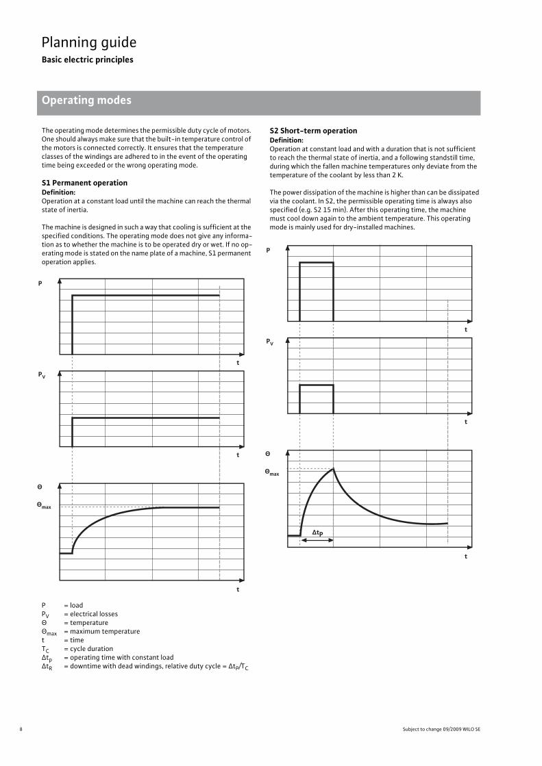
Planning guide Basic electric principles Operating modes Subject to change 09/2009 WILO SE Wilo catalogue C 3.1 - 50 Hz – Pumps stations and solids separation systemThe operating mode determines the permissible duty cycle of motors. One should always make sure that the built-in temperature control of the motors is connected correctly. It ensures that the temperature classes of the windings are adhered to in the event of the operating time being exceeded or the wrong operating mode.
S1 Permanent operationDefinition:Operation at a constant load until the machine can reach the thermal state of inertia.
The machine is designed in such a way that cooling is sufficient at the specified conditions. The operating mode does not give any informa-tion as to whether the machine is to be operated dry or wet. If no op-erating mode is stated on the name plate of a machine, S1 permanent operation applies.
P = loadPV = electrical losses � = temperature �max = maximum temperature t = timeTC = cycle duration �tp = operating time with constant load�tR = downtime with dead windings, relative duty cycle = �tP/TC
S2 Short-term operationDefinition:Operation at constant load and with a duration that is not sufficient to reach the thermal state of inertia, and a following standstill time, during which the fallen machine temperatures only deviate from the temperature of the coolant by less than 2 K.
The power dissipation of the machine is higher than can be dissipated via the coolant. In S2, the permissible operating time is always also specified (e.g. S2 15 min). After this operating time, the machine must cool down again to the ambient temperature. This operating mode is mainly used for dry-installed machines.
P
t
t
t
PV
Θ
Θmax
P
t
t
t
PV
Θ
ΔtP
Θmax

9
Planning guideBasic electric principles
Operating modes
Wilo catalogue C 3.1 - 50 Hz – Pumps stations and solids separation system
S3 Intermittent operation without affecting the starting currentDefinition:Operation that consists of a sequence of identical cycles, each one consisting of an operating time with constant load and a downtime, and the starting current does not have a significant effect on the ex-cess temperature.
The power dissipation of the machine is higher than can be dissipated via the coolant. In S3 operating mode, the cycle duration is specified in percent and the cycle time is also specified.
Example for S3 25 % 10 min: The duty cycle is 2.5 min and the pause is 7.5 min. If no cycle duration is specified, the cycle duration of 10 min applies.
P = loadPV = electrical losses � = temperature �max = maximum temperature t = timeTC = cycle duration �tp = operating time with constant load�tR = downtime with dead windings, relative duty cycle = �tP/TC
P
t
t
t
PV
Θ
ΔtP ΔtR
TC
Θmax
10 Subject to change 09/2009 WILO SE
Planning guideBasic electric principles
Explosion protection
Planning guide Basic electric principles Explosion protection Subject to change 09/2009 WILO SE Wilo catalogue C 3.1 - 50 Hz – Pumps stations and solids separation systemWilo units are approved for use in potentially explosive areas. For this, they are certified according to two different standards: The European ATEX standard as well as the American FM standard.
Atex standard The units are designed in accordance with "EU Directive 94/ 09/EC" (ATEX 95) and the European standards DIN EN 60079-0 and EN 60079-1. They may be operated in potentially explosive atmos-pheres which require electrical devices of device group II, category 2.
It is therefore possible to use them in zone 1 and zone 2. These units may not be used in zone 0.
The Wilo units are labelled as follows: II 2 G Ex d IIB T4
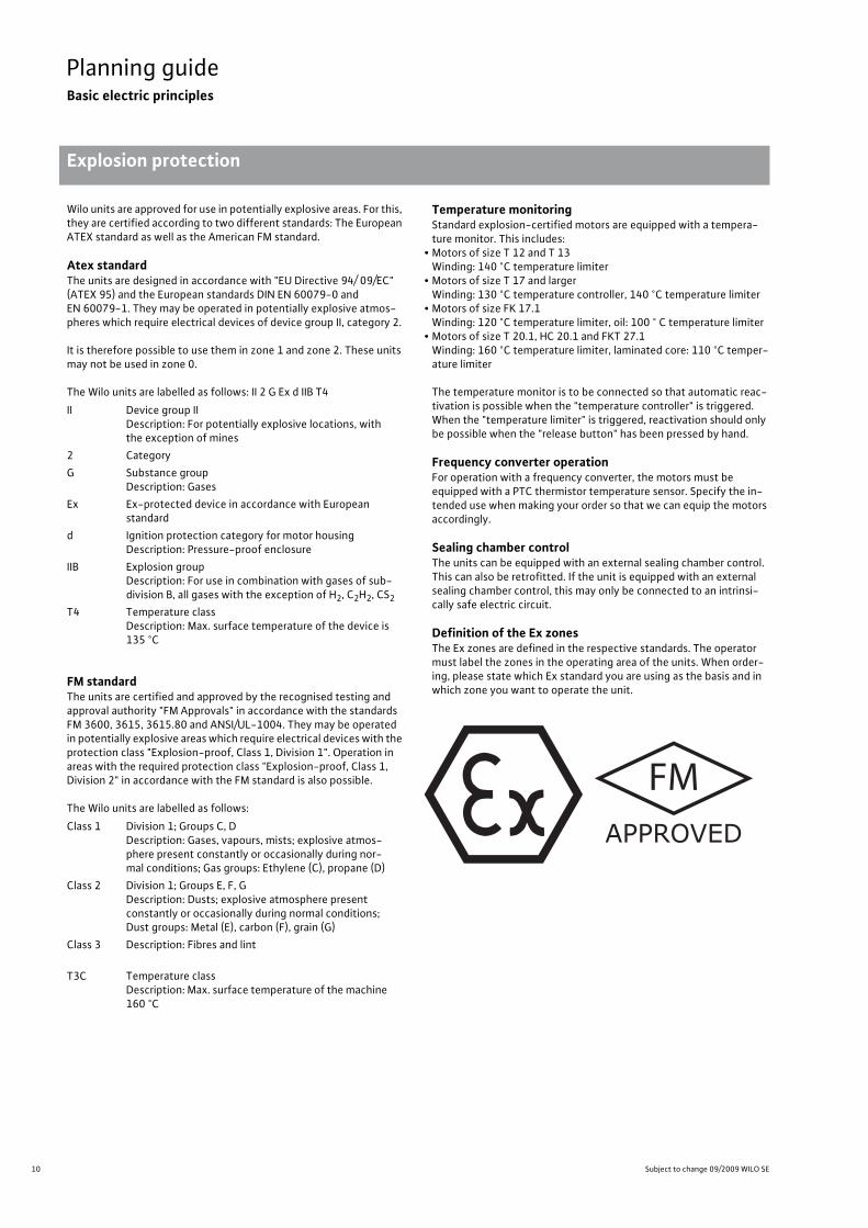
FM standardThe units are certified and approved by the recognised testing and approval authority "FM Approvals" in accordance with the standards FM 3600, 3615, 3615.80 and ANSI/UL-1004. They may be operated in potentially explosive areas which require electrical devices with the protection class "Explosion-proof, Class 1, Division 1". Operation in areas with the required protection class "Explosion-proof, Class 1, Division 2" in accordance with the FM standard is also possible.
The Wilo units are labelled as follows:
Temperature monitoringStandard explosion-certified motors are equipped with a tempera-ture monitor. This includes:
• Motors of size T 12 and T 13Winding: 140 °C temperature limiter
• Motors of size T 17 and largerWinding: 130 °C temperature controller, 140 °C temperature limiter
• Motors of size FK 17.1Winding: 120 °C temperature limiter, oil: 100 ° C temperature limiter
• Motors of size T 20.1, HC 20.1 and FKT 27.1Winding: 160 °C temperature limiter, laminated core: 110 °C temper-ature limiter
The temperature monitor is to be connected so that automatic reac-tivation is possible when the "temperature controller" is triggered. When the "temperature limiter" is triggered, reactivation should only be possible when the "release button" has been pressed by hand.
Frequency converter operationFor operation with a frequency converter, the motors must be equipped with a PTC thermistor temperature sensor. Specify the in-tended use when making your order so that we can equip the motors accordingly.
Sealing chamber control The units can be equipped with an external sealing chamber control. This can also be retrofitted. If the unit is equipped with an external sealing chamber control, this may only be connected to an intrinsi-cally safe electric circuit.
Definition of the Ex zonesThe Ex zones are defined in the respective standards. The operator must label the zones in the operating area of the units. When order-ing, please state which Ex standard you are using as the basis and in which zone you want to operate the unit.
II Device group IIDescription: For potentially explosive locations, with the exception of mines
2 CategoryG Substance group
Description: GasesEx Ex-protected device in accordance with European
standardd Ignition protection category for motor housing
Description: Pressure-proof enclosureIIB Explosion group
Description: For use in combination with gases of sub-division B, all gases with the exception of H2, C2H2, CS2
T4 Temperature classDescription: Max. surface temperature of the device is 135 °C
Class 1 Division 1; Groups C, DDescription: Gases, vapours, mists; explosive atmos-phere present constantly or occasionally during nor-mal conditions; Gas groups: Ethylene (C), propane (D)
Class 2 Division 1; Groups E, F, GDescription: Dusts; explosive atmosphere present constantly or occasionally during normal conditions; Dust groups: Metal (E), carbon (F), grain (G)
Class 3 Description: Fibres and lint
T3C Temperature classDescription: Max. surface temperature of the machine 160 °C
FMAPPROVED

11
Planning guideBasic electric principles
Level measuring systems
Wilo catalogue C 3.1 - 50 Hz – Pumps stations and solids separation system
Planning guide Basic electric principles Level measuring systems Subject to change 09/2009 WILO SE Wilo catalogue C 3.1 - 50 Hz – Pumps stations and solids separation systemLevel measuring systems are for measuring the water level in tanks. Depending on the application conditions, various systems are availa-ble.
Float switchWith this method, switching contacts are closed or opened in a float-ing body according to the inclination angle. With float switches, one should always make sure that they can move freely in the sump. They can also be used in potentially explosive areas if they are operated via an ex-rated cut-off relay (Ex-i).
A basic distinction must be made between two different designs:
Single-point float switch:These floaters have a short connection to the cable with a slight dif-ference between the activation point and deactivation point. Some of these floaters are also available as heavy versions that tilt around their centre of gravity. To avoid the constant switching of the pump, at least two of these floaters must be used for level control. Due to their good floating properties, however, they are better suited for sewage applications.
Two-point float switch:These float switches have a larger angle between activation point and deactivation point. They are fastened to their pipe. That makes it possible to switch smaller differences with only one float switch ac-cording to the drawn-out pipe length.
1
0
12 Subject to change 09/2009 WILO SE
Planning guideBasic electric principles
Level measuring systems
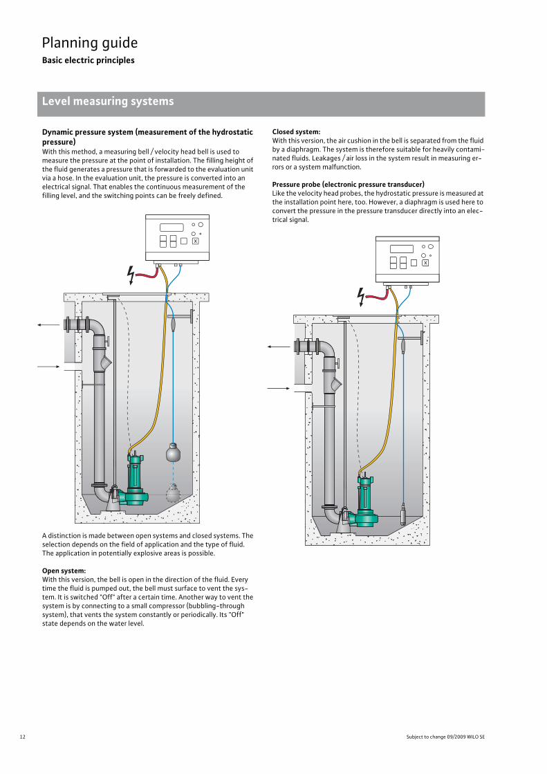
Dynamic pressure system (measurement of the hydrostatic pressure)With this method, a measuring bell / velocity head bell is used to measure the pressure at the point of installation. The filling height of the fluid generates a pressure that is forwarded to the evaluation unit via a hose. In the evaluation unit, the pressure is converted into an electrical signal. That enables the continuous measurement of the filling level, and the switching points can be freely defined.
A distinction is made between open systems and closed systems. The selection depends on the field of application and the type of fluid. The application in potentially explosive areas is possible.
Open system:With this version, the bell is open in the direction of the fluid. Every time the fluid is pumped out, the bell must surface to vent the sys-tem. It is switched "Off" after a certain time. Another way to vent the system is by connecting to a small compressor (bubbling-through system), that vents the system constantly or periodically. Its "Off" state depends on the water level.
Closed system:With this version, the air cushion in the bell is separated from the fluid by a diaphragm. The system is therefore suitable for heavily contami-nated fluids. Leakages / air loss in the system result in measuring er-rors or a system malfunction.
Pressure probe (electronic pressure transducer)Like the velocity head probes, the hydrostatic pressure is measured at the installation point here, too. However, a diaphragm is used here to convert the pressure in the pressure transducer directly into an elec-trical signal.

13
Planning guideBasic electric principles
Level measuring systems
Wilo catalogue C 3.1 - 50 Hz – Pumps stations and solids separation system
Conductivity (conductive measurement method)In this case, submersible electrodes are connected to an evaluation relay. The relay detects whether fluid is present or not based on the resistance. The trigger resistance can be set on most relays. In this way, simple level controls for filling or draining can be implemented. The application as a dry-running protection system is also very fre-quent. Not suitable for sewage pumping stations.
UltrasoundMeasurement with ultrasound is based on the measurement of the running time. The ultrasonic pulses emitted by a sensor are reflected by the surface of the fluid and detected by the sensor. The required running time is a measure for the distance covered in the empty tank. This value is deducted from the overall tank height, which results in the filling level.
The advantage of this method is that measurement of the filling level in the tank is possible without contact, regardless of the fluid. During installation, one should ensure that the measuring cone emitted by the sensor is free of installations. A minimum clearance to the wall of the tank must also be kept.

14 Subject to change 09/2009 WILO SE
Pressure drainagePumps stations
Series overview Wilo-DrainLift WS
Pressure drainage Pumps stations Series overview Wilo-DrainLift WS Subject to change 09/2009 WILO SE Wilo catalogue C 3.1 - 50 Hz – Pumps stations and solids separation system
Series: Wilo-DrainLift WS 625
>ApplicationWastewater and sewage pumping station for drainage and pressure drainage, outside the building as pumps station in accordance with EN 752.
� � �
H[m
]
0
25
20
15
10
5
Q[m³/h]6 8 10 12 14 16420
Wilo-DrainLiftWS 625
TMW 32/11MTS 40/21...27TC 40, STS 40
Series: Wilo-DrainLift WS 830
>ApplicationWastewater and sewage pumping station for drainage and pressurised drainage, out-side the building as pumps station in ac-cordance with EN 752.
�
0
25
15
20
10
5
H[m
]
30
80 4 10 12 Q[m³/h]1462
Wilo-DrainLiftWS 830
MTC 40.../MTS 40...
Series: Wilo-DrainLift WS 900/1100
>ApplicationWastewater and sewage pumping station for drainage and pressure drainage, outside the building as pumps station in accordance with EN 752.
� � �
Q[m³/h]50 60 70 9030 402010 8000
10
20
30
40
H[m
]
Wilo-DrainLiftWS 900/WS 1100
MTC 32MTC 40MTS 40TS 40TP 50TP 65
STS 65TP 80

15
Pressure drainagePumps stations
Pres
sure
dra
inag
e
Series overview Wilo-DrainLift WS
Wilo catalogue C 3.1 - 50 Hz – Pumps stations and solids separation system
Pressure drainage Pumps stations Series overview Wilo-DrainLift WS Subject to change 09/2009 WILO SE Wilo catalogue C 3.1 - 50 Hz – Pumps stations and solids separation system
Series: Wilo-DrainLift WS 625
>Special features/product advantages• Small sump diameter (625 mm)• Flexible utilisation due to different installation heights• Inlet connection is included with DN 100 as a standard• Complete through integrated fittings and gaskets• Can be walked over or driven over, depending on the covering (accessories)• Also with macerator pumps Wilo-Drain MTS 40/21...27
>Additional information Page• Equipment/function . . . . . . . . . . . . . . 18• Series description. . . . . . . . . . . . . . . . . 19• Pump curves . . . . . . . . . . . . . . . . . . . . . 20• Technical data. . . . . . . . . . . . . . . . . . . . 21• Dimensions, weights . . . . . . . . . . . . . . 21• Installation example . . . . . . . . . . . . . . 23• Mechanical accessories. . . . . . . . . . . . 24
Series: Wilo-DrainLift WS 830
>Special features/product advantages• Removable angle non-return ball valve on pump discharge pipe• Monolithic sump in 2 installation depths: 1800 mm and 2500 mm• Upward pressure reliability with groundwater level up to ground surface level, without addi-
tional concrete• Gate valve can be operated from above• High installation guide for easier installing of the pump pipe in the case of high water levels in
the sump
>Additional information Page• Equipment/function . . . . . . . . . . . . . . 18• Series description. . . . . . . . . . . . . . . . . 26• Pump curves . . . . . . . . . . . . . . . . . . . . . 27• Technical data. . . . . . . . . . . . . . . . . . . . 28• Dimensions, weights . . . . . . . . . . . . . . 28• Installation example . . . . . . . . . . . . . . 30
Series: Wilo-DrainLift WS 900/1100
>Special features/product advantages• Deposit-free collection room• Maximum stability through the use of hemispherical sump floor• 2/4 inlets can be selected onsite• Pumps station ready for connection (without pump and switchgear)• V4A stainless steel pipework• Also with macerator pumps Wilo-Drain MTS 40/21..39.
>Additional information Page• Equipment/function . . . . . . . . . . . . . . 18• Series description. . . . . . . . . . . . . . . . . 32• Pump curves . . . . . . . . . . . . . . . . . . . . . 33• Technical data. . . . . . . . . . . . . . . . . . . . 34• Dimensions, weights . . . . . . . . . . . . . . 36• Mechanical accessories. . . . . . . . . . . . 38
16 Subject to change 09/2009 WILO SE
Pressure drainageSubmersible pumps with macerator
Series overview Wilo-Drain MTC, MTS
Pressure drainage Submersible pumps with macerator Series overview Wilo-Drain MTC, MTS Subject to change 09/2009 WILO SE Wilo catalogue C 3.1 - 50 Hz – Pumps stations and solids separation system
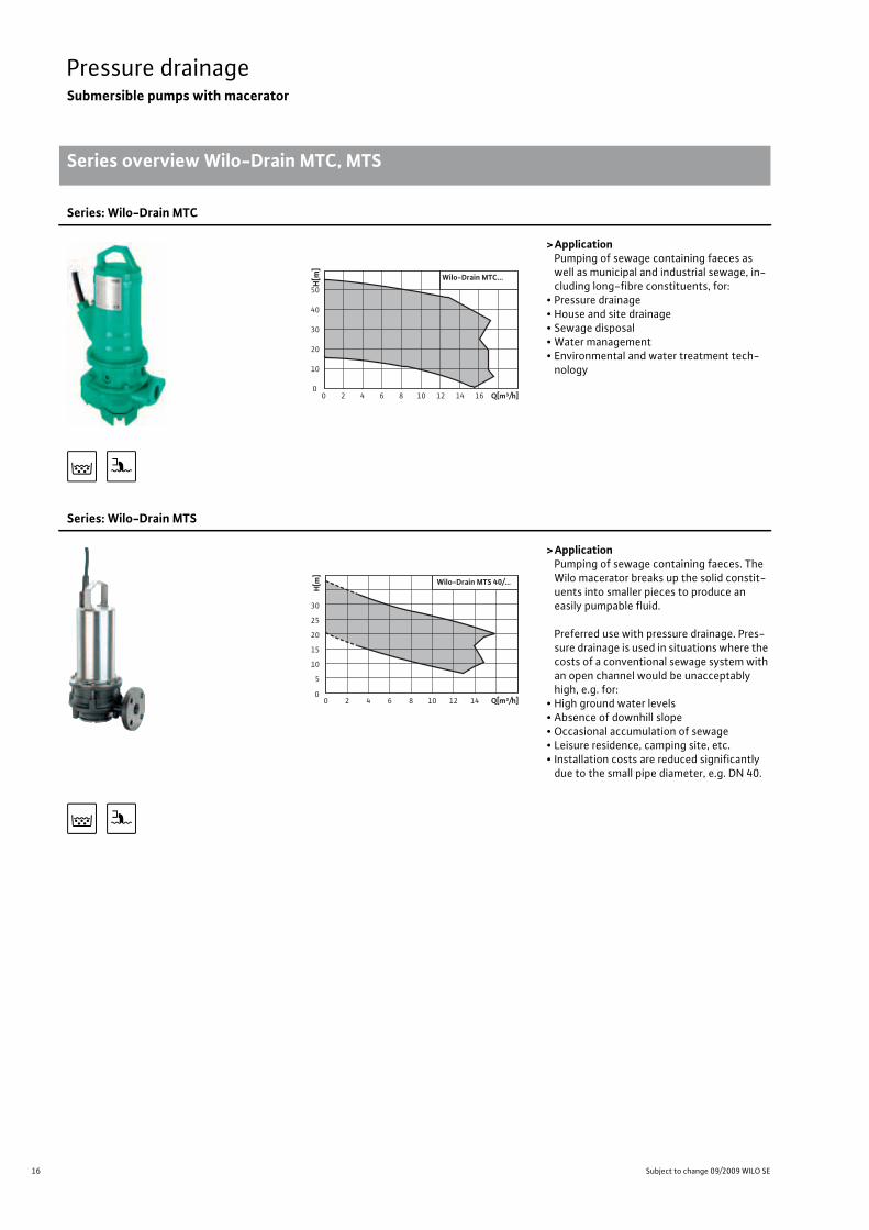
Series: Wilo-Drain MTC
>ApplicationPumping of sewage containing faeces as well as municipal and industrial sewage, in-cluding long-fibre constituents, for:
• Pressure drainage• House and site drainage• Sewage disposal• Water management• Environmental and water treatment tech-nology
�
0
10
20
30
40
50
H[m
]
0 2 4 6 8 10 12 14 16 Q[m³/h]
Wilo-Drain MTC...
Series: Wilo-Drain MTS
>ApplicationPumping of sewage containing faeces. The Wilo macerator breaks up the solid constit-uents into smaller pieces to produce an easily pumpable fluid.
Preferred use with pressure drainage. Pres-sure drainage is used in situations where the costs of a conventional sewage system with an open channel would be unacceptably high, e.g. for:
• High ground water levels• Absence of downhill slope• Occasional accumulation of sewage• Leisure residence, camping site, etc.• Installation costs are reduced significantly due to the small pipe diameter, e.g. DN 40.
�
H[m
]
0
25
30
20
15
10
5
Q[m³/h]6 8 10 12 14420
Wilo-Drain MTS 40/...

17
Pressure drainageSubmersible pumps with macerator
Pres
sure
dra
inag
e
Series overview Wilo-Drain MTC, MTS
Wilo catalogue C 3.1 - 50 Hz – Pumps stations and solids separation system
Pressure drainage Submersible pumps with macerator Series overview Wilo-Drain MTC, MTS Subject to change 09/2009 WILO SE Wilo catalogue C 3.1 - 50 Hz – Pumps stations and solids separation system
Series: Wilo-Drain MTC
>Special features/product advantages• Oil barrier chamber• Mechanical seal on pump side made of solid silicon carbide material• Hardened macerator• Longitudinally watertight cable (for MTC 32)• Version with explosion protection (optional for MTC 32)
>Additional information Page• Series description. . . . . . . . . . . . . . . . . 42
Series: Wilo-Drain MTS
>Special features/product advantages• Spherically formed macerator• High degree of efficiency• Low operating costs• Resistant to clogging and blockage• Oil barrier chamber• High operational reliability• Corrosion-resistant stainless steel motor in 1.4404 (316 L)• Explosion protection as standard for all 3~400 V versions
>Additional information Page• Series description. . . . . . . . . . . . . . . . . 58
18 Subject to change 09/2009 WILO SE
Pressure drainagePumps stations
Equipment/functionPressure drainage Pumps stations Equipment/function Subject to change 09/2009 WILO SE Wilo catalogue C 3.1 - 50 Hz – Pumps stations and solids separation system
• = can be used, - = can not be used
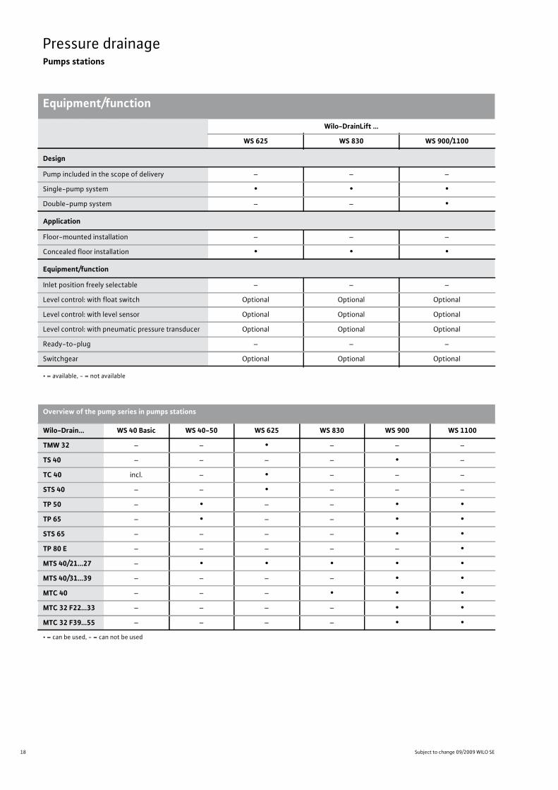
Wilo-DrainLift ...
WS 625 WS 830 WS 900/1100
Design
Pump included in the scope of delivery – – –
Single-pump system • • •Double-pump system – – •
Application
Floor-mounted installation – – –
Concealed floor installation • • •
Equipment/function
Inlet position freely selectable – – –
Level control: with float switch Optional Optional Optional
Level control: with level sensor Optional Optional Optional
Level control: with pneumatic pressure transducer Optional Optional Optional
Ready-to-plug – – –
Switchgear Optional Optional Optional
• = available, - = not available
Overview of the pump series in pumps stations
Wilo-Drain... WS 40 Basic WS 40-50 WS 625 WS 830 WS 900 WS 1100
TMW 32 – – • – – –
TS 40 – – – – • –
TC 40 incl. – • – – –
STS 40 – – • – – –
TP 50 – • – – • •TP 65 – • – – • •STS 65 – – – – • •TP 80 E – – – – – •MTS 40/21...27 – • • • • •MTS 40/31...39 – – – – • •MTC 40 – – – • • •MTC 32 F22...33 – – – – • •MTC 32 F39...55 – – – – • •

19
Pressure drainagePumps stations
Pressure
drainage
Series description Wilo-DrainLift WS 625
Wilo catalogue C 3.1 - 50 Hz – Pumps stations and solids separation system
Pressure drainage Pumps stations Series description Wilo-DrainLift WS 625 Subject to change 09/2009 WILO SE Wilo catalogue C 3.1 - 50 Hz – Pumps stations and solids separation system
Synthetic pumps stations
Type key
ApplicationWilo-DrainLift WS 625 is a single pump sump for pumping wastewa-ter and sewage in building services out of rooms and from areas un-derneath the backflow level (EN 752). It is suitable as a pumps station for pressurised drainage and as a pumping station for pressurised drainage. The WS 625 is installed in the ground outside of the build-ing. A time-saving, easy-to-install, low-cost solution for all planners and developers.
Applicable pump types
TMW 32/11Slightly contaminated fluids (free of faeces), 10 mm free ball passage.
STS 40 and TC 40For severely contaminated fluids (free of faeces);
MTS 40/21...27For severely contaminated fluids and faeces. Standard-equipped ex-plosion protection (only 3~400 V), detachable connection cable. With a spherical macerator non-susceptible to plugging that contains an internal rotating blade.
Special features/product advantages• Small sump diameter (625 mm)• Flexible utilisation due to different installation heights• Inlet connection is included with DN 100 as a standard• Complete through integrated fittings and gaskets• Can be walked over or driven over, depending on the covering
(accessories)• Also with macerator pumps Wilo-Drain MTS 40/21...27
Description/designWilo-DrainLift WS 625 is available in 4 lengths: 1200, 1500, 1800 and 2100 mm. The sump can be equipped with a standard cover that can be walked on as well as Class A (can be walked on) or Class B/D (can be driven over) covers.
• Maximum pressure in the pressure pipe 6 bar in conjunction with MTS 40, other pumps 4 bar
• Synthetic pumps station made of recyclable PE• Highest degree of upward pressure reliability and inherent stability by means of finning up to a ground water level above the entire sump height (upper edge of site)
Scope of delivery• PE sump with internal pipework including coupling sleeve slider 1 ¼" and non-return valve (integrated in pump with TMW 32/11)
• Gasket mounted for inlet DN 100• Gasket mounted for ventilation/electrical connection (DN 100).• Gasket mounted for pressure pipeline (DN 40 / �50).• Pump (including floor supporting foot with MTS 40) with matching discharge pipe
• Installation and operating instructions.
Choice of switchgear and level probe as accessories.
Recommendations for electrical accessories are described in the "Wilo Drain electrical accessories" chapter.
Example: Wilo-DrainLift WS 625 E / 1800 MTS 40WS Synthetic pumping station625 Inside diameter of sump [mm]E Single pump sump1800 Sump height [mm]MTS 40/... Selected pump type MTS 40/21...27
STS 40: Free ball passage 40 mmTC 40: Free ball passage 40 mm
20 Subject to change 09/2009 WILO SE
Pressure drainagePumps stations
Pump curves, ordering information Wilo-DrainLift WS 625
Pressure drainage Pumps stations Pump curves, ordering information Wilo-DrainLift WS 625 Subject to change 09/2009 WILO SE Wilo catalogue C 3.1 - 50 Hz – Pumps stations and solids separation system
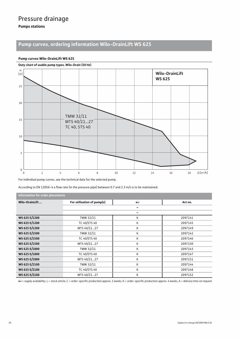
Pump curves Wilo-DrainLift WS 625
Duty chart of usable pump types, Wilo-Drain (50 Hz)
For individual pump curves, see the technical data for the selected pump.
According to EN 12056-4 a flow rate (in the pressure pipe) between 0.7 and 2.3 m/s is to be maintained.
H[m]
0
25
20
15
10
5
Q [m³/h]6 8 10 12 14 16 18420
Wilo-DrainLiftWS 625
TMW 32/11MTS 40/21...27TC 40, STS 40
Information for order placements
Wilo-DrainLift ... For utilisation of pump(s) Art no.––
WS 625 E/1200 TMW 32/11 K 2097141
WS 625 E/1200 TC 40/STS 40 K 2097145
WS 625 E/1200 MTS 40/21...27 K 2097149
WS 625 E/1500 TMW 32/11 K 2097142
WS 625 E/1500 TC 40/STS 40 K 2097146
WS 625 E/1500 MTS 40/21...27 K 2097150
WS 625 E/1800 TMW 32/11 K 2097143
WS 625 E/1800 TC 40/STS 40 K 2097147
WS 625 E/1800 MTS 40/21...27 K 2097151
WS 625 E/2100 TMW 32/11 K 2097144
WS 625 E/2100 TC 40/STS 40 K 2097148
WS 625 E/2100 MTS 40/21...27 K 2097152
�= supply availability, L = stock article, C = order-specific production approx. 2 weeks, K = order-specific production approx. 4 weeks, A = delivery time on request

21
Pressure drainagePumps stations
Wilo catalogue C 3.1 - 50 Hz – Pumps stations and solids separation system
Technical data, dimensions Wilo-DrainLift WS 625
Pressure
drainage
Pressure drainage Pumps stations Technical data, dimensions Wilo-DrainLift WS 625 Subject to change 09/2009 WILO SE Wilo catalogue C 3.1 - 50 Hz – Pumps stations and solids separation system
WS 625 E/1200 WS 625 E/1500
TMW 32/11 TC 40/STS 40 MTS 40/21...27
TMW 32/11 TC 40/STS 40 MTS 40/21...27
Gross volume [l] 368 368 368 460 460 460
Impoundment volume (floor to top of inlet) 167 167 167 167 167 167
Effective volume [l] 61 116 103 61 116 103
Remaining water reserves [l] 15 12 64 15 12 64
Max. permissible pressure in pressure pipe [bar] 4 4 6 4 4 6
Pressure connection DN 40 DN 40 DN 40 DN 40 DN 40 DN 40
Air vent valve DN 100 DN 100 DN 100 DN 100 DN 100 DN 100
Free ball passage [mm] 10 40 10 10 40 10
Weight approx. [kg] 32 33 35 39 40 42
Technical data
WS 625 E/1800 WS 625 E/2100
TMW 32/11 TC 40/STS 40 MTS 40/21...27
TMW 32/11 TC 40/STS 40 MTS 40/21...27
Gross volume [l] 552 552 552 644 644 644
Impoundment volume (floor to top of inlet) 167 167 167 167 167 167
Effective volume [l] 61 116 103 61 116 103
Remaining water reserves [l] 15 12 64 15 12 64
Max. permissible pressure in pressure pipe [bar] 4 4 6 4 4 6
Pressure connection DN 40 DN 40 DN 40 DN 40 DN 40 DN 40
Air vent valve DN 100 DN 100 DN 100 DN 100 DN 100 DN 100
Free ball passage [mm] 10 40 10 10 40 10
Weight approx. [kg] 47 48 49 55 56 57
Dimensions
Wilo-DrainLift ... Installation depth below ground surface level up to inlet floor
Dimensions
without extension with extension A B[mm]
WS 625 E/1200 655 - 1260 600
WS 625 E/1500 955 - 1560 900
WS 625 E/1800 1255 - 1860 1200
WS 625 E/2100 1555 - 2160 1500

22 Subject to change 09/2009 WILO SE
Pressure drainagePumps stations
Dimension drawing Wilo-DrainLift WS 625
Pressure drainage Pumps stations Dimension drawing Wilo-DrainLift WS 625 Subject to change 09/2009 WILO SE Wilo catalogue C 3.1 - 50 Hz – Pumps stations and solids separation system
Dimension drawing Wilo-DrainLift WS 625 E/1200
Dimension drawing Wilo-DrainLift WS 625 E/1500...2100
Ø625
600
Ø50
400 300
Ø715 60DN10
0 : Ø
110
500
B
A
30°
TMW 32/11 STS 40TC 40
Ø625
840
Ø50
400 300
Ø715 60DN10
0 : Ø
110
AØ11
060
0
B
TMW 32/11 STS 40TC 40
23
Pressure drainagePumps stations
Pressure
drainage
Installation example Wilo-DrainLift WS 625
Wilo catalogue C 3.1 - 50 Hz – Pumps stations and solids separation system
Pressure drainage Pumps stations Installation example Wilo-DrainLift WS 625 Subject to change 09/2009 WILO SE Wilo catalogue C 3.1 - 50 Hz – Pumps stations and solids separation system
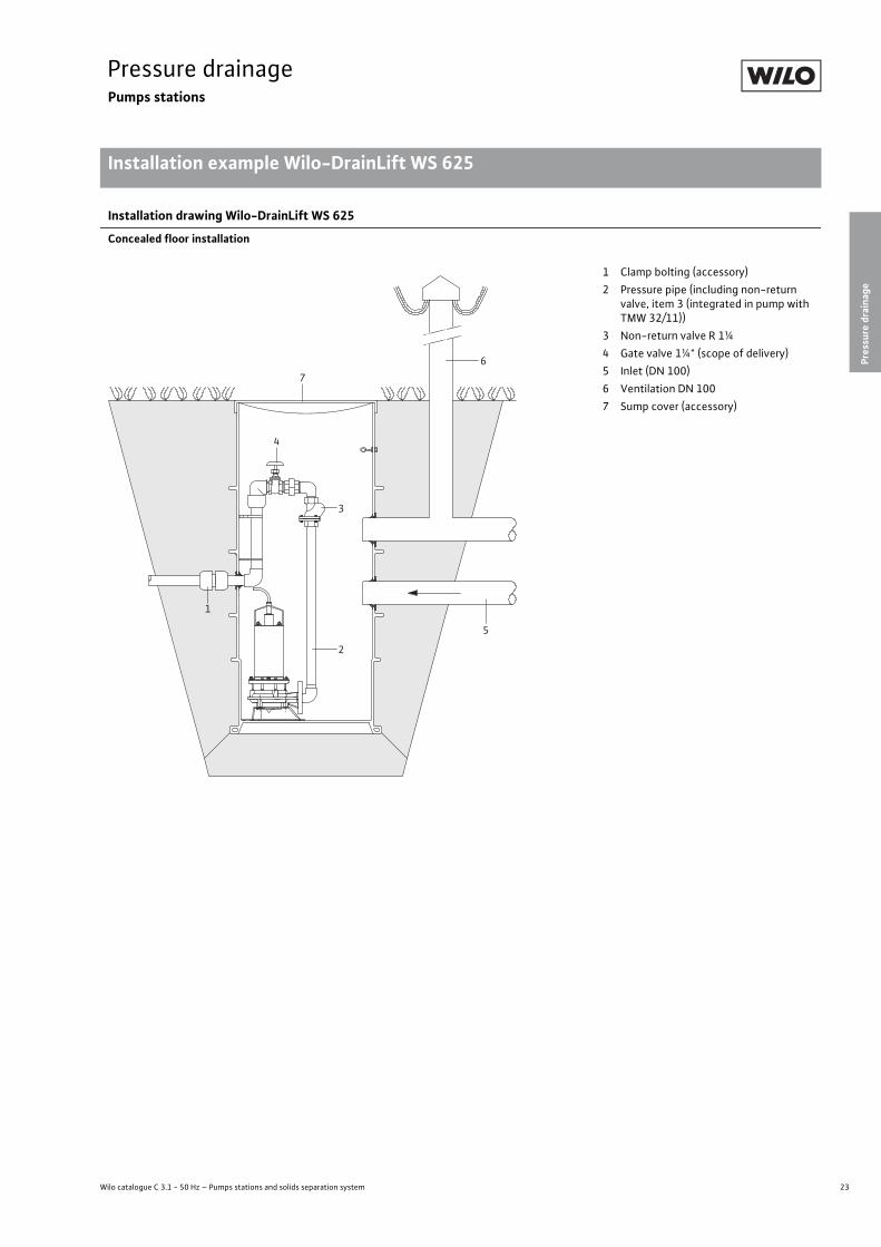
Installation drawing Wilo-DrainLift WS 625
Concealed floor installation
6
3
2
5
7
4
1
1 Clamp bolting (accessory)2 Pressure pipe (including non-return
valve, item 3 (integrated in pump with TMW 32/11))
3 Non-return valve R 1¼4 Gate valve 1¼" (scope of delivery)5 Inlet (DN 100)6 Ventilation DN 1007 Sump cover (accessory)
24 Subject to change 09/2009 WILO SE
Pressure drainagePumps stations
Mechanical accessories Wilo-DrainLift WS 625
Pressure drainage Pumps stations Mechanical accessories Wilo-DrainLift WS 625 Subject to change 09/2009 WILO SE Wilo catalogue C 3.1 - 50 Hz – Pumps stations and solids separation system
Mechanical accessories
- Description Art no.––
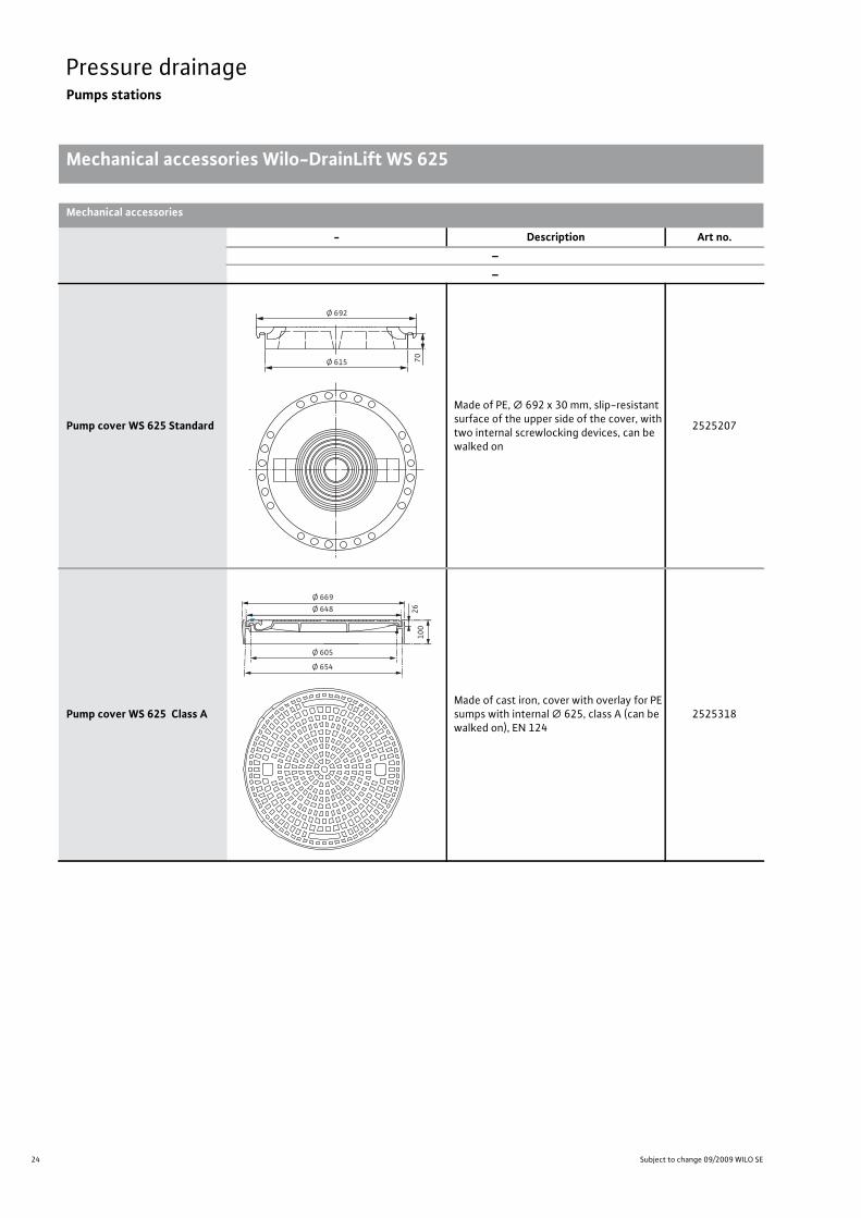
Pump cover WS 625 Standard
Made of PE, � 692 x 30 mm, slip-resistant surface of the upper side of the cover, with two internal screwlocking devices, can be walked on
2525207
Pump cover WS 625 Class AMade of cast iron, cover with overlay for PE sumps with internal � 625, class A (can be walked on), EN 124
2525318
Ø 692
Ø 615 7026
100
Ø 648Ø 669
Ø 605
Ø 654

25
Pressure drainagePumps stations
Pressure
drainage
Mechanical accessories Wilo-DrainLift WS 625
Wilo catalogue C 3.1 - 50 Hz – Pumps stations and solids separation system
Pump cover WS 625 Class BMade of cast iron with concrete (BEGU), co-ver with overlay for PE sumps with inside � 625, Class B (can be driven over), EN 124
2525319
Pump cover WS 625 Class D
Made of cast iron with concrete (BEGU), cover with self-supporting overlay for PE sumps with inside � 625, Class D (can be driven over), EN 124
2525320
Clamp boltingMade of PP, for the connection of a PE pressure pipe outside the sump with 50 x 50 mm pipe diameter
2525183
Clamp boltingMade of PP, for the connection of a PE pressure pipe outside the sump with 50 x 63 mm pipe diameter
2525184
Mechanical accessories
- Description Art no.––
Ø 670
Ø 648
Ø 604
Ø 654
2610
0
Ø 707
Ø 684
Ø 680
R331Ø 610
Ø 665
50
60
160
810
1107
26 Subject to change 09/2009 WILO SE
Pressure drainagePumps stations
Series description Wilo-DrainLift WS 830
Pressure drainage Pumps stations Series description Wilo-DrainLift WS 830 Subject to change 09/2009 WILO SE Wilo catalogue C 3.1 - 50 Hz – Pumps stations and solids separation system
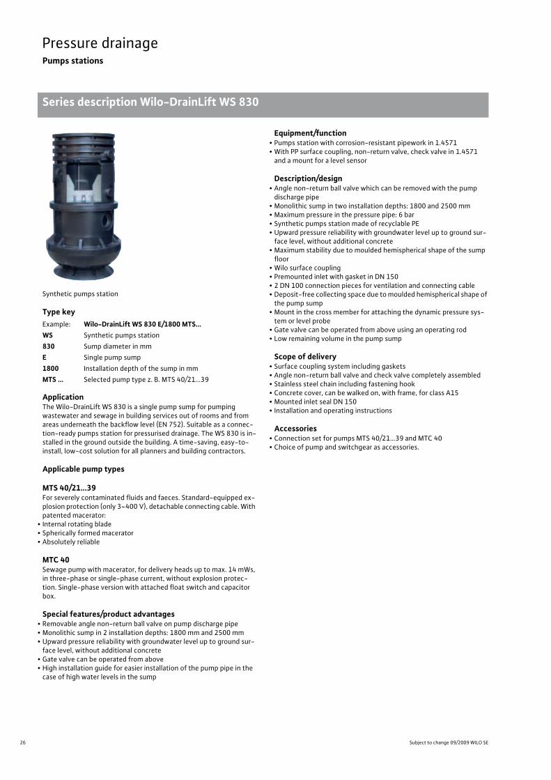
Synthetic pumps station
Type key
ApplicationThe Wilo-DrainLift WS 830 is a single pump sump for pumping wastewater and sewage in building services out of rooms and from areas underneath the backflow level (EN 752). Suitable as a connec-tion-ready pumps station for pressurised drainage. The WS 830 is in-stalled in the ground outside the building. A time-saving, easy-to-install, low-cost solution for all planners and building contractors.
Applicable pump types
MTS 40/21…39For severely contaminated fluids and faeces. Standard-equipped ex-plosion protection (only 3~400 V), detachable connecting cable. With patented macerator:
• Internal rotating blade• Spherically formed macerator• Absolutely reliable
MTC 40Sewage pump with macerator, for delivery heads up to max. 14 mWs, in three-phase or single-phase current, without explosion protec-tion. Single-phase version with attached float switch and capacitor box.
Special features/product advantages• Removable angle non-return ball valve on pump discharge pipe• Monolithic sump in 2 installation depths: 1800 mm and 2500 mm• Upward pressure reliability with groundwater level up to ground sur-face level, without additional concrete
• Gate valve can be operated from above• High installation guide for easier installation of the pump pipe in the case of high water levels in the sump
Equipment/function• Pumps station with corrosion-resistant pipework in 1.4571• With PP surface coupling, non-return valve, check valve in 1.4571 and a mount for a level sensor
Description/design• Angle non-return ball valve which can be removed with the pump discharge pipe
• Monolithic sump in two installation depths: 1800 and 2500 mm• Maximum pressure in the pressure pipe: 6 bar• Synthetic pumps station made of recyclable PE• Upward pressure reliability with groundwater level up to ground sur-face level, without additional concrete
• Maximum stability due to moulded hemispherical shape of the sump floor
• Wilo surface coupling• Premounted inlet with gasket in DN 150• 2 DN 100 connection pieces for ventilation and connecting cable• Deposit-free collecting space due to moulded hemispherical shape of the pump sump
• Mount in the cross member for attaching the dynamic pressure sys-tem or level probe
• Gate valve can be operated from above using an operating rod• Low remaining volume in the pump sump
Scope of delivery• Surface coupling system including gaskets• Angle non-return ball valve and check valve completely assembled• Stainless steel chain including fastening hook• Concrete cover, can be walked on, with frame, for class A15• Mounted inlet seal DN 150• Installation and operating instructions
Accessories• Connection set for pumps MTS 40/21...39 and MTC 40• Choice of pump and switchgear as accessories.
Example: Wilo-DrainLift WS 830 E/1800 MTS…WS Synthetic pumps station830 Sump diameter in mmE Single pump sump1800 Installation depth of the sump in mmMTS … Selected pump type z. B. MTS 40/21...39
27
Pressure drainagePumps stations
Pressure
drainage
Pump curves, ordering information Wilo-DrainLift WS 830
Wilo catalogue C 3.1 - 50 Hz – Pumps stations and solids separation system
Pressure drainage Pumps stations Pump curves, ordering information Wilo-DrainLift WS 830 Subject to change 09/2009 WILO SE Wilo catalogue C 3.1 - 50 Hz – Pumps stations and solids separation system
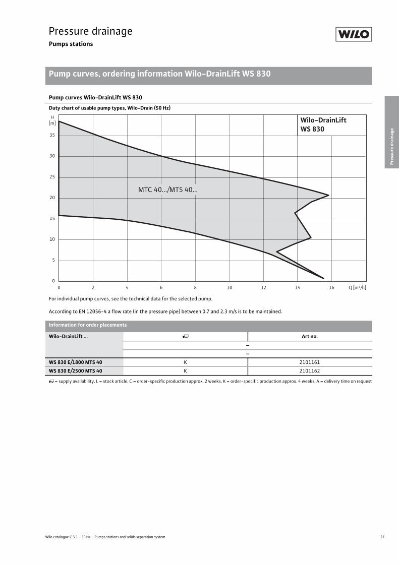
Pump curves Wilo-DrainLift WS 830
Duty chart of usable pump types, Wilo-Drain (50 Hz)
For individual pump curves, see the technical data for the selected pump.
According to EN 12056-4 a flow rate (in the pressure pipe) between 0.7 and 2.3 m/s is to be maintained.
0
25
15
20
10
5
H[m]
35
30
80 4 10 12 16 Q [m³/h]1462
Wilo-DrainLiftWS 830
MTC 40.../MTS 40...
Information for order placements
Wilo-DrainLift ... Art no.––
WS 830 E/1800 MTS 40 K 2101161
WS 830 E/2500 MTS 40 K 2101162
�= supply availability, L = stock article, C = order-specific production approx. 2 weeks, K = order-specific production approx. 4 weeks, A = delivery time on request
28 Subject to change 09/2009 WILO SE
Pressure drainagePumps stations
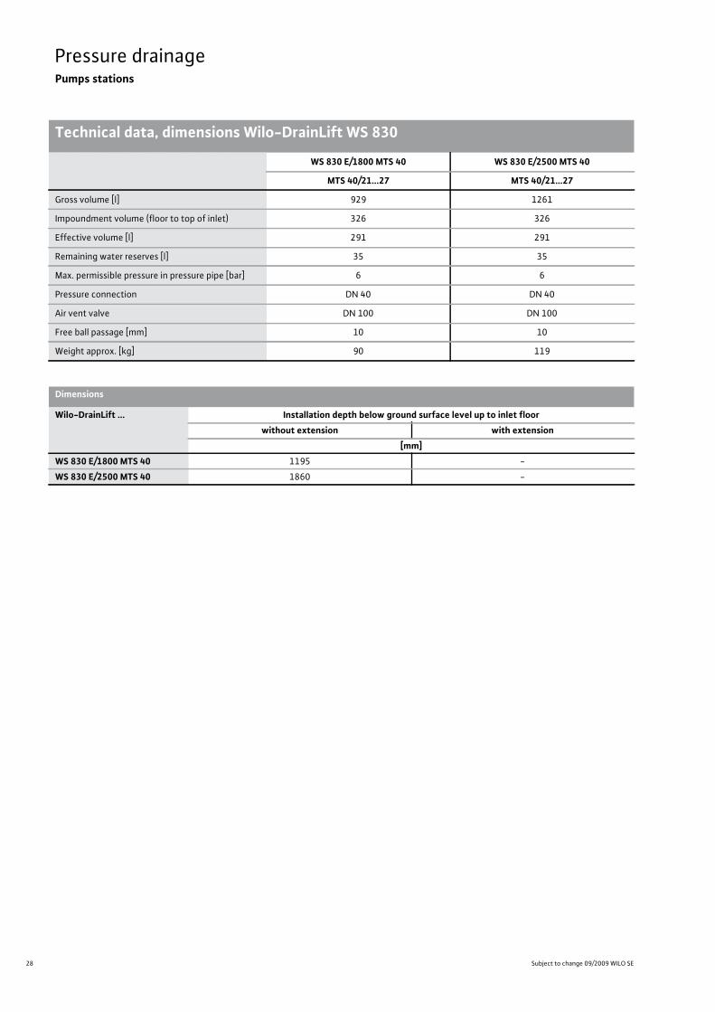
Technical data, dimensions Wilo-DrainLift WS 830Pressure drainage Pumps stations Technical data, dimensions Wilo-DrainLift WS 830 Subject to change 09/2009 WILO SE Wilo catalogue C 3.1 - 50 Hz – Pumps stations and solids separation system
WS 830 E/1800 MTS 40 WS 830 E/2500 MTS 40
MTS 40/21...27 MTS 40/21...27
Gross volume [l] 929 1261
Impoundment volume (floor to top of inlet) 326 326
Effective volume [l] 291 291
Remaining water reserves [l] 35 35
Max. permissible pressure in pressure pipe [bar] 6 6
Pressure connection DN 40 DN 40
Air vent valve DN 100 DN 100
Free ball passage [mm] 10 10
Weight approx. [kg] 90 119
Dimensions
Wilo-DrainLift ... Installation depth below ground surface level up to inlet floorwithout extension with extension
[mm]WS 830 E/1800 MTS 40 1195 -
WS 830 E/2500 MTS 40 1860 -

29
Pressure drainagePumps stations
Pressure
drainage
Dimension drawing Wilo-DrainLift WS 830
Wilo catalogue C 3.1 - 50 Hz – Pumps stations and solids separation system
Pressure drainage Pumps stations Dimension drawing Wilo-DrainLift WS 830 Subject to change 09/2009 WILO SE Wilo catalogue C 3.1 - 50 Hz – Pumps stations and solids separation system
Dimension drawing Wilo-DrainLift WS 830 E/1800
Dimension drawing Wilo-DrainLift WS 830 E/2500
Ø810
Da 50
1195
755
830
75
1820
450
670
Ø1000
45°
DN 150
Ø810
Da 50
1860
1420
1495
75
2485
450
670
Ø1000
45°
DN 150
30 Subject to change 09/2009 WILO SE
Pressure drainagePumps stations
Installation example Wilo-DrainLift WS 830
Pressure drainage Pumps stations Installation example Wilo-DrainLift WS 830 Subject to change 09/2009 WILO SE Wilo catalogue C 3.1 - 50 Hz – Pumps stations and solids separation system
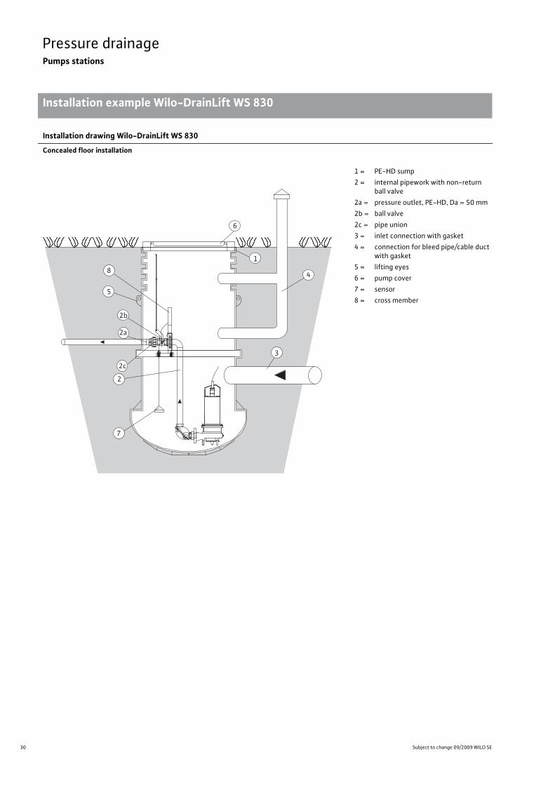
Installation drawing Wilo-DrainLift WS 830
Concealed floor installation
6
1
4
3
5
8
7
2b
2a
2
2c
1 = PE-HD sump2 = internal pipework with non-return
ball valve2a = pressure outlet, PE-HD, Da = 50 mm2b = ball valve2c = pipe union3 = inlet connection with gasket4 = connection for bleed pipe/cable duct
with gasket5 = lifting eyes6 = pump cover7 = sensor8 = cross member
31
Pressure drainagePumps stations
Pressure
drainage
Installation example Wilo-DrainLift WS 830
Wilo catalogue C 3.1 - 50 Hz – Pumps stations and solids separation system
Pressure drainage Pumps stations Installation example Wilo-DrainLift WS 830 Subject to change 09/2009 WILO SE Wilo catalogue C 3.1 - 50 Hz – Pumps stations and solids separation system
32 Subject to change 09/2009 WILO SE
Pressure drainagePumps stations
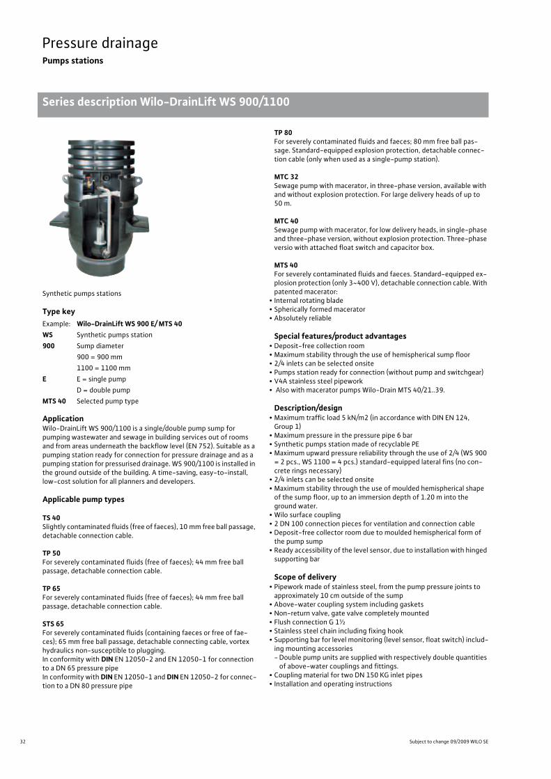
Series description Wilo-DrainLift WS 900/1100
Pressure drainage Pumps stations Series description Wilo-DrainLift WS 900/1100 Subject to change 09/2009 WILO SE Wilo catalogue C 3.1 - 50 Hz – Pumps stations and solids separation system
Synthetic pumps stations
Type key
ApplicationWilo-DrainLift WS 900/1100 is a single/double pump sump for pumping wastewater and sewage in building services out of rooms and from areas underneath the backflow level (EN 752). Suitable as a pumping station ready for connection for pressure drainage and as a pumping station for pressurised drainage. WS 900/1100 is installed in the ground outside of the building. A time-saving, easy-to-install, low-cost solution for all planners and developers.
Applicable pump types
TS 40Slightly contaminated fluids (free of faeces), 10 mm free ball passage, detachable connection cable.
TP 50For severely contaminated fluids (free of faeces); 44 mm free ball passage, detachable connection cable.
TP 65For severely contaminated fluids (free of faeces); 44 mm free ball passage, detachable connection cable.
STS 65For severely contaminated fluids (containing faeces or free of fae-ces); 65 mm free ball passage, detachable connecting cable, vortex hydraulics non-susceptible to plugging.In conformity with DIN EN 12050-2 and EN 12050-1 for connection to a DN 65 pressure pipeIn conformity with DIN EN 12050-1 and DIN EN 12050-2 for connec-tion to a DN 80 pressure pipe
TP 80For severely contaminated fluids and faeces; 80 mm free ball pas-sage. Standard-equipped explosion protection, detachable connec-tion cable (only when used as a single-pump station).
MTC 32Sewage pump with macerator, in three-phase version, available with and without explosion protection. For large delivery heads of up to 50 m.
MTC 40Sewage pump with macerator, for low delivery heads, in single-phase and three-phase version, without explosion protection. Three-phase versio with attached float switch and capacitor box.
MTS 40For severely contaminated fluids and faeces. Standard-equipped ex-plosion protection (only 3~400 V), detachable connection cable. With patented macerator:
• Internal rotating blade• Spherically formed macerator• Absolutely reliable
Special features/product advantages• Deposit-free collection room• Maximum stability through the use of hemispherical sump floor• 2/4 inlets can be selected onsite• Pumps station ready for connection (without pump and switchgear)• V4A stainless steel pipework• Also with macerator pumps Wilo-Drain MTS 40/21..39.
Description/design• Maximum traffic load 5 kN/m2 (in accordance with DIN EN 124, Group 1)
• Maximum pressure in the pressure pipe 6 bar• Synthetic pumps station made of recyclable PE• Maximum upward pressure reliability through the use of 2/4 (WS 900
= 2 pcs., WS 1100 = 4 pcs.) standard-equipped lateral fins (no con-crete rings necessary)
• 2/4 inlets can be selected onsite• Maximum stability through the use of moulded hemispherical shape of the sump floor, up to an immersion depth of 1.20 m into the ground water.
• Wilo surface coupling• 2 DN 100 connection pieces for ventilation and connection cable• Deposit-free collector room due to moulded hemispherical form of the pump sump
• Ready accessibility of the level sensor, due to installation with hinged supporting bar
Scope of delivery• Pipework made of stainless steel, from the pump pressure joints to approximately 10 cm outside of the sump
• Above-water coupling system including gaskets• Non-return valve, gate valve completely mounted• Flush connection G 1½• Stainless steel chain including fixing hook• Supporting bar for level monitoring (level sensor, float switch) includ-ing mounting accessories-Double pump units are supplied with respectively double quantities of above-water couplings and fittings.
• Coupling material for two DN 150 KG inlet pipes• Installation and operating instructions
Example: Wilo-DrainLift WS 900 E/ MTS 40WS Synthetic pumps station 900 Sump diameter
900 = 900 mm1100 = 1100 mm
E E = single pumpD = double pump
MTS 40 Selected pump type
33
Pressure drainagePumps stations
Pressure
drainage
Pump curves, ordering information Wilo-DrainLift WS 900/1100
Wilo catalogue C 3.1 - 50 Hz – Pumps stations and solids separation system
Pressure drainage Pumps stations Pump curves, ordering information Wilo-DrainLift WS 900/1100 Subject to change 09/2009 WILO SE Wilo catalogue C 3.1 - 50 Hz – Pumps stations and solids separation system
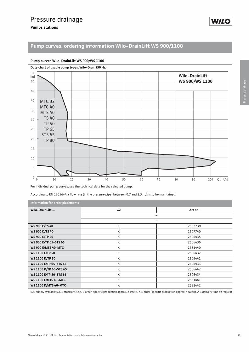
Pump curves Wilo-DrainLift WS 900/WS 1100
Duty chart of usable pump types, Wilo-Drain (50 Hz)
For individual pump curves, see the technical data for the selected pump.
According to EN 12056-4 a flow rate (in the pressure pipe) between 0.7 and 2.3 m/s is to be maintained.
Q [m³/h]50 60 70 90 10030 402010 8000
5
10
15
20
25
30
35
40
45
50
H[m] Wilo-DrainLift
WS 900/WS 1100
MTC 32MTC 40MTS 40TS 40TP 50TP 65
STS 65TP 80
Information for order placements
Wilo-DrainLift ... Art no.––
WS 900 E/TS 40 K 2507739
WS 900 D/TS 40 K 2507740
WS 900 E/TP 50 K 2506435
WS 900 E/TP 65-STS 65 K 2506436
WS 900 E/MTS 40-MTC K 2531440
WS 1100 E/TP 50 K 2506432
WS 1100 D/TP 50 K 2506441
WS 1100 E/TP 65-STS 65 K 2506433
WS 1100 D/TP 65-STS 65 K 2506442
WS 1100 E/TP 80-STS 65 K 2506434
WS 1100 E/MTS 40-MTC K 2531441
WS 1100 D/MTS 40-MTC K 2531442
= supply availability, L = stock article, C = order-specific production approx. 2 weeks, K = order-specific production approx. 4 weeks, A = delivery time on request

34 Subject to change 09/2009 WILO SE
Pressure drainagePumps stations
Technical data Wilo-DrainLift WS 900/1100Pressure drainage Pumps stations Technical data Wilo-DrainLift WS 900/1100 Subject to change 09/2009 WILO SE Wilo catalogue C 3.1 - 50 Hz – Pumps stations and solids separation system
Wilo-DrainLift ...
WS 900 E/TS 40
WS 900 D/TS 40
WS 900 E/TP 50
WS 900 E/TP 65-STS 65
WS 900 E/MTS 40-MTC
WS 1100 E/TP 50
Gross volume [l] 890 880 890 890 880 1230
Impoundment volume (floor to top of inlet) 300 290 300 300 290 540
Effective volume [l] 150 110 140 130 150 200
Remaining water reserves [l] 82.5 196.5 94 143 82.5 101
Max. permissible pressure in pressure pipe [bar] 6 6 6 6 6 6
Pressure connection Rp 1½ Rp 1½ Rp 2 Rp 2½ Rp 1½ Rp 2
Air vent valve DN 100 DN 100 DN 100 DN 100 DN 100 DN 100
Free ball passage [mm] 10 10 44 44 10 44
Weight approx. [kg] 70 95 73 75 72 95
35
Pressure drainagePumps stations
Wilo catalogue C 3.1 - 50 Hz – Pumps stations and solids separation system
Technical data Wilo-DrainLift WS 900/1100
Pres
sure
dra
inag
e
Pressure drainage Pumps stations Technical data Wilo-DrainLift WS 900/1100 Subject to change 09/2009 WILO SE Wilo catalogue C 3.1 - 50 Hz – Pumps stations and solids separation system
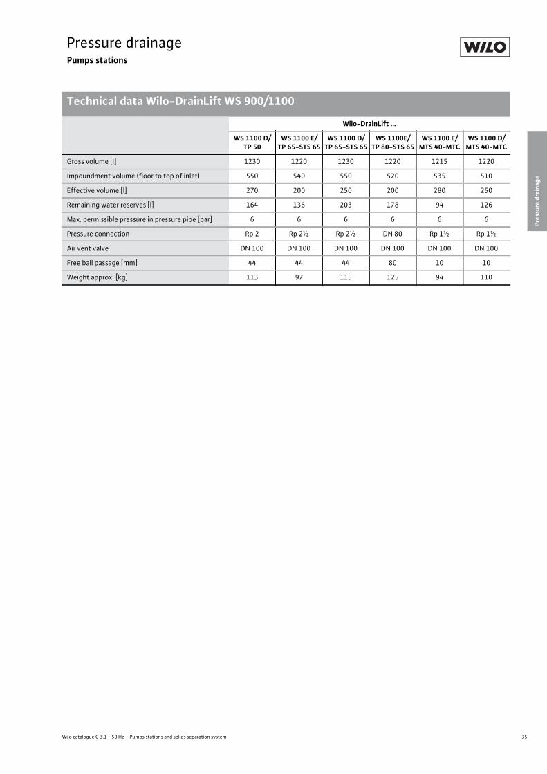
Wilo-DrainLift ...
WS 1100 D/TP 50
WS 1100 E/TP 65-STS 65
WS 1100 D/TP 65-STS 65
WS 1100E/TP 80-STS 65
WS 1100 E/MTS 40-MTC
WS 1100 D/MTS 40-MTC
Gross volume [l] 1230 1220 1230 1220 1215 1220
Impoundment volume (floor to top of inlet) 550 540 550 520 535 510
Effective volume [l] 270 200 250 200 280 250
Remaining water reserves [l] 164 136 203 178 94 126
Max. permissible pressure in pressure pipe [bar] 6 6 6 6 6 6
Pressure connection Rp 2 Rp 2½ Rp 2½ DN 80 Rp 1½ Rp 1½
Air vent valve DN 100 DN 100 DN 100 DN 100 DN 100 DN 100
Free ball passage [mm] 44 44 44 80 10 10
Weight approx. [kg] 113 97 115 125 94 110
36 Subject to change 09/2009 WILO SE
Pressure drainagePumps stations
Dimension drawing Wilo-DrainLift WS 900/1100
Pressure drainage Pumps stations Dimension drawing Wilo-DrainLift WS 900/1100 Subject to change 09/2009 WILO SE Wilo catalogue C 3.1 - 50 Hz – Pumps stations and solids separation system
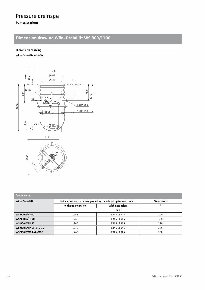
Dimension drawing
Wilo-DrainLift WS 900
A
Ø 840
Ø 740
G 1½
405100
OFF
830
Ø856
560
1800
740
1170
A
430
315
195
A
1260
45°
2 x DN150
2 x DN100
Dimensions
Wilo-DrainLift ... Installation depth below ground surface level up to inlet floor Dimensionswithout extension with extension A
[mm]WS 900 E/TS 40 1245 1345...1945 200
WS 900 D/TS 40 1245 1345...1945 354
WS 900 E/TP 50 1245 1345...1945 220
WS 900 E/TP 65-STS 65 1245 1345...1945 285
WS 900 E/MTS 40-MTC 1245 1345...1945 200

37
Pressure drainagePumps stations
Pressure
drainage
Dimension drawing Wilo-DrainLift WS 900/1100
Wilo catalogue C 3.1 - 50 Hz – Pumps stations and solids separation system
Dimension drawing
Wilo-DrainLift WS 1100
22,5°
45°
4x90
°=36
0°4 x DN150
1500
527
100
OFF
1500
2 x DN100
625
1800
765
1095
675
A
375
250
125
Ø1084
G 1½“
A
AØ 840
Ø 740
Dimensions
Wilo-DrainLift ... Installation depth below ground surface level up to inlet floor Dimensionswithout extension with extension A
[mm]WS 1100 E/TP 50 1170 1270...1870 230
WS 1100 D/TP 50 1170 1270...1870 310
WS 1100 E/TP 65-STS 65 1170 1270...1870 260
WS 1100 D/TP 65-STS 65 1170 1270...1870 360
WS 1100 E/TP 80-STS 65 1170 1270...1870 330
WS 1100 E/MTS 40-MTC 1170 1270...1870 220
WS 1100 D/MTS 40-MTC 1170 1270...1870 260

38 Subject to change 09/2009 WILO SE
Pressure drainagePumps stations
Mechanical accessories Wilo-DrainLift WS 900/1100
Pressure drainage Pumps stations Mechanical accessories Wilo-DrainLift WS 900/1100 Subject to change 09/2009 WILO SE Wilo catalogue C 3.1 - 50 Hz – Pumps stations and solids separation system
Mechanical accessories
- Description Art no.
––
Pump cover WS900/1100 Standard
Made of PE, � 830 x 52 mm, slip-resistant surface of the upper side of the cover, with two internal locking devices, can be walked on
2506477
Pump cover WS 900/1100 "overflow-proof"
Made of PE, � 960 x 100 mm, secure against flooding thanks to integrated gas-ket, slip-resistant surface of the upper side of the cover, with six stainless steel lock-ings with effect to the outside, can be walked on
2506478
Sump length extension WS900/1100
Made of PE, � 730 x 800, for WS900/1100 sumps, including gasket, mounting acces-sories and supporting bar extension for le-vel sensor Only 1 extension per sump is possible. Other extensions are not permit-ted.
2506431
Clamp bolting
Made of PE, with female thread (IG), for the connection to a PE-pressure pipe outside the sump 1½" (IG) with 50 mm pipe diame-ter
2505044
Clamp bolting
Made of PE, with female thread (IG), for the connection to a PE-pressure pipe outside the sump 1½" (IG) with 63 mm pipe diame-ter
2505045
Clamp boltingMade of PE, with female thread (IG), for the connection to a PE-pressure pipe outside the sump 2" (IG) with 63 mm pipe diameter
2505046
39
Pressure drainagePumps stations
Pressure
drainage
Mechanical accessories Wilo-DrainLift WS 900/1100
Wilo catalogue C 3.1 - 50 Hz – Pumps stations and solids separation system
Pressure drainage Pumps stations Mechanical accessories Wilo-DrainLift WS 900/1100 Subject to change 09/2009 WILO SE Wilo catalogue C 3.1 - 50 Hz – Pumps stations and solids separation system

40 Subject to change 09/2009 WILO SE
Pressure drainageSubmersible pumps with macerator
Equipment/functionPressure drainage Submersible pumps with macerator Equipment/function Subject to change 09/2009 WILO SE Wilo catalogue C 3.1 - 50 Hz – Pumps stations and solids separation system
Wilo-Drain MTC Wilo-Drain MTS
Design
Submersible • •Single-channel impeller – •Vortex impeller – –
Multi-channel impeller – –
Open multi-channel impeller • –
Macerator • •Turbulator – –
Sealing chamber • •Leakage chamber - -
Sealing for mechanical seal on motor side • –
Sealing for rotary shaft seal on motor side • •Sealing for mechanical seal on fluid side • •Single-phase motor • •Three-phase motor • •Direct activation • •Star-delta activation • –
FC operation – –
Dry motor • •Motor with oil cooling - -
Dry motor with closed-circuit cooling - -
Application
Wet well installation, stationary • •Wet well installation, portable • •Dry well installation, stationary – –
Dry well installation, portable – –
Equipment/function
Motor leakage monitoring – –
Sealing chamber monitoring optional –
Leakage chamber monitoring - -
Motor temperature monitoring, bimetal • •Motor temperature monitoring, PTC – –
• = can be pumped, - = cannot be pumped, o = can be pumped to a limited extent

41
Pressure drainageSubmersible pumps with macerator
Wilo catalogue C 3.1 - 50 Hz – Pumps stations and solids separation system
Equipment/function
Pressure
drainage
Pressure drainage Submersible pumps with macerator Equipment/function Subject to change 09/2009 WILO SE Wilo catalogue C 3.1 - 50 Hz – Pumps stations and solids separation system
Wilo-Drain MTC Wilo-Drain MTS
Equipment/function
Explosion protection • •
Float switch•1~
–
Capacitor box for 1~230 V • •
Ready-to-plug•1~
•1~
Materials
Pump housing Cast iron Cast iron
Impeller Cast iron Cast iron
Motor housing Cast iron Stainless steel
• = can be pumped, - = cannot be pumped, o = can be pumped to a limited extent
42 Subject to change 09/2009 WILO SE
Pressure drainageSubmersible pumps with macerator
Series description Wilo-Drain MTC
Pressure drainage Submersible pumps with macerator Series description Wilo-Drain MTC Subject to change 09/2009 WILO SE Wilo catalogue C 3.1 - 50 Hz – Pumps stations and solids separation system
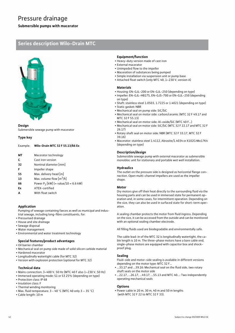
DesignSubmersible sewage pump with macerator
Type key
ApplicationPumping of sewage containing faeces as well as municipal and indus-trial sewage, including long-fibre constituents, for:
• Pressurised drainage• House and site drainage• Sewage disposal• Water management• Environmental and water treatment technology
Special features/product advantages• Oil barrier chamber• Mechanical seal on pump side made of solid silicon carbide material• Hardened macerator• Longitudinally watertight cable (for MTC 32)• Version with explosion protection (optional for MTC 32)
Technical data• Mains connection: 3~400 V, 50 Hz (MTC 40 F also 1~230 V, 50 Hz)• Immersed operating mode: S1 or S3 25% (depending on type)• Protection class: IP 68• Insulation class: F• Thermal winding monitoring• Max. fluid temperature: 3 - 40 °C (MTC 40 only 3 – 35 °C)• Cable length: 10 m
Equipment/function• Heavy-duty version made of cast iron• External macerator• Unimpeded flow to the impeller• Maceration of substances being pumped• Simple installation via suspension unit or pump base• Attached float switch (only MTC 40, 1~230 V, version A)
Materials• Housing: EN-GJL-200 or EN-GJL-250 (depending on type)• Impeller: EN-GJL-HB175, EN-GJS-700 or EN-GJL-250 (depending on type)
• Shaft: stainless steel 1.0503, 1.7225 or 1.4021 (depending on type)• Static gasket: NBR• Mechanical seal on pump side: SiC/SiC• Mechanical seal on motor side: carbon/ceramic (MTC 32 F 49.17 and MTC 32 F 55.13)
• Mechanical seal on motor side: Al-oxide/SiC (MTC 40 F...)• Mechanical seal on motor side: SiC/SiC (MTC 32 F 22.17 and MTC 32 F 26.17)
• Rotary shaft seal on motor side: NBR (MTC 32 F 33.17, MTC 32 F 39.16)
• Macerator: stainless steel 1.4112, Abrasite/1.4034 or X102CrMo17K4 (depending on type)
Description/designSubmersible sewage pump with external macerator as submersible monobloc unit for stationary and portable wet well installation.
HydraulicsThe outlet on the pressure side is designed as horizontal flange con-nection. Open multi-channel impellers are used as the impeller shape.
MotorDry motors give off their heat directly to the surrounding fluid via the housing parts and can be used in immersed state for permanent op-eration and, in some cases, for intermittent operation. Depending on the size, they can also be used in surfaced state for short-term oper-ation.
A sealing chamber protects the motor from fluid ingress. Depending on the size, it can be accessed from the outside and can be monitored with an optional sealing chamber electrode.
All filling fluids used are biodegradable and environmentally safe.
The cable lead-in of the MTC 32 is longitudinally watertight, the ca-ble length is 10 m. The three-phase motors have a bare cable end, single-phase motors are equipped with capacitor box and shock-proof plug.
SealingFluid-side and motor-side sealing is available in different versions depending on the motor type: MTC 32 F...
• ...33.17 and ...39.16: Mechanical seal on the fluid side, two rotary shaft seals on the motor side
• ...22.17, ...26.17, ...49.17, ...55.13 and MTC 40...: Two independently operating mechanical seals
Options• Power cable in 20 m, 30 m, 40 m and 50 m lengths
(with MTC 32 F 22 to MTC 32 F 33).
Example: Wilo-Drain MTC 32 F 55.13/66 Ex
MT Macerator technologyC Cast iron version32 Nominal diameter [mm]F Impeller shape55 Max. delivery head [m]13 Max. volume flow [m3/h]66 Power P2 [kW] (= value/10 = 6.6 kW)Ex ATEX-certifiedA With float switch
43
Pressure drainageSubmersible pumps with macerator
Pressure
drainage
Series description Wilo-Drain MTC
Wilo catalogue C 3.1 - 50 Hz – Pumps stations and solids separation system
Scope of delivery• Pump ready for connection with 10 m connection cable- For 3~400 V with bare cable end- For 1~230 V with shock-proof plug
• A-model version with attached float switch• Installation and operating instructions
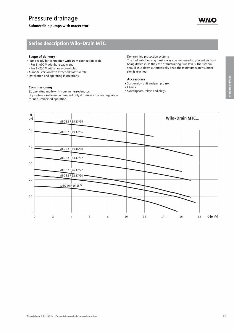
CommissioningS1 operating mode with non-immersed motor:Dry motors can be non-immersed only if there is an operating mode for non-immersed operation.
Dry-running protection system:The hydraulic housing must always be immersed to prevent air from being drawn in. In the case of fluctuating fluid levels, the system should shut down automatically once the minimum water submer-sion is reached.
Accessories• Suspension unit and pump base• Chains• Switchgears, relays and plugs
0
10
20
30
40
50
H[m]
0 2 4 6 8 10 12 14 16 18 Q [m³/h]
MTC 32 F 55.13/66
MTC 32 F 49.17/66
MTC 32 F 33.17/37
MTC 32 F 26.17/22
MTC 32 F 22.17/20
MTC 40 F 16.15/7
MTC 32 F 39.16/30
Wilo-Drain MTC...

44 Subject to change 09/2009 WILO SE
Pressure drainageSubmersible pumps with macerator
Technical data Wilo-Drain MTCPressure drainage Submersible pumps with macerator Technical data Wilo-Drain MTC Subject to change 09/2009 WILO SE Wilo catalogue C 3.1 - 50 Hz – Pumps stations and solids separation system
MTC 40 F 16.15/7-A
MTC 40 F 16.15/7
MTC 32 F 22.17/20 Ex
MTC 32 F 26.17/22 Ex
MTC 32 F 33.17/37 Ex
MTC 32 F 39.16/30
1~230 V, 50 Hz 3~400 V, 50 Hz 3~400 V, 50 Hz 3~400 V, 50 Hz 3~400 V, 50 Hz 3~400 V, 50 Hz
Unit
Pressure connection Rp 1½/DN 40 Rp 1½/DN 40 DN 36/G 1¼/G 2
DN 36/G 1¼/G 2
DN 36/G 1¼/G 2 DN 32
Max. volume flow [m3/h] 15 15 17 17 17 16
Max. delivery head [m] 16 16 22 26 33 39
Operating mode (immersed)S1
S3-25%S1
S3-25%S1 S1 S1
S1S3-25%
Operating mode (non-immersed) - - S2-15 min. - S2-15 min. -
Max. immersion depth [m] 20 20 12.5 12.5 12.5 10
Protection class IP 68 IP 68 IP 68 IP 68 IP 68 IP 68
Fluid temperature +3 °C ... +35 °C +3 °C ... +35 °C +3 °C ... +40 °C +3 °C ... +40 °C +3 °C ... +40 °C +3 °C ... +40 °C
Weight approx. [kg] 20 20 33 33 49 43
Motor data
Nominal current [A] 5.6 2.5 4.45 4.8 7.6 7.3
Starting current [A] - - 26 25 37 43
Nominal motor power [kW] 0.7 0.7 2 2.25 3.75 3.42
Power consumption [kW] 1.2 1.2 2.6 3 4.7 4.2
Power factor - - 0.85 0.87 0.9 0.84
Activation type direct direct direct direct direct direct
Nominal speed [rpm] 2900 2900 2900 2900 2900 2900
Insulation class F F F F F F
Recommended switching frequency [1/h] 25 25 20 20 20 20
Max. switching frequency [1/h] 50 50 50 50 50 50
Permitted voltage tolerance [%] +/- 10 +/- 10 +/- 10 +/- 10 +/- 10 +/- 10
Cable
Length of connection cable [m] 10 10 10 10 10 10
Cable type H07RN-F H07RN-F H07RN-F H07RN-F H07RN-F H07RN-F
Cable cross-section [mm2] 4G1 4G1 7G1.5 7G1.5 7G1.5 6G1.5
Type of connection cable non-detacha-ble
non-detacha-ble
non-detacha-ble
non-detacha-ble
non-detacha-ble
non-detacha-ble
Mains plug Schuko - - - - -

45
Pressure drainageSubmersible pumps with macerator
Wilo catalogue C 3.1 - 50 Hz – Pumps stations and solids separation system
Technical data Wilo-Drain MTC
Pressure
drainage
Pressure drainage Submersible pumps with macerator Technical data Wilo-Drain MTC Subject to change 09/2009 WILO SE Wilo catalogue C 3.1 - 50 Hz – Pumps stations and solids separation system
MTC 32 F 39.16/30 Ex
MTC 32 F 49.17/66
MTC 32 F 49.17/66 Ex
MTC 32 F 55.13/66
MTC 32 F 55.13/66 Ex
3~400 V, 50 Hz 3~400 V, 50 Hz 3~400 V, 50 Hz 3~400 V, 50 Hz 3~400 V, 50 Hz
Unit
Pressure connection DN 32 DN 32 DN 32 DN 32 DN 32
Max. volume flow [m3/h] 16 17 17 13 13
Max. delivery head [m] 39 49 49 55 55
Operating mode (immersed)S1
S3-25%S1
S3-25%S1
S3-25%S1
S3-25%S1
S3-25%
Operating mode (non-immersed) - - - - -
Max. immersion depth [m] 10 10 10 10 10
Protection class IP 68 IP 68 IP 68 IP 68 IP 68
Fluid temperature +3 °C ... +40 °C +3 °C ... +40 °C +3 °C ... +40 °C +3 °C ... +40 °C +3 °C ... +40 °C
Weight approx. [kg] 43 90 90 90 90
Motor data
Nominal current [A] 7.3 13.2 13.2 13.2 13.2
Starting current [A] 43 58 58 58 58
Nominal motor power [kW] 3.42 6.6 6.6 6.6 6.6
Power consumption [kW] 4.2 7.7 7.7 7.7 7.7
Power factor 0.84 0.86 0.86 0.86 0.86
Activation type direct star-delta star-delta star-delta star-delta
Nominal speed [rpm] 2900 2900 2900 2900 2900
Insulation class F F F F F
Recommended switching frequency [1/h] 20 20 20 20 20
Max. switching frequency [1/h] 50 50 50 50 50
Permitted voltage tolerance [%] +/- 10 +/- 10 +/- 10 +/- 10 +/- 10
Cable
Length of connection cable [m] 10 10 10 10 10
Cable type H07RN-F H07RN-F H07RN-F H07RN-F H07RN-F
Cable cross-section [mm2] 6G1.5 10G2.5 10G2.5 10G2.5 10G2.5
Type of connection cable non-detachable non-detachable non-detachable non-detachable non-detachable
Mains plug - - - - -
46 Subject to change 09/2009 WILO SE
Pressure drainageSubmersible pumps with macerator
Technical data Wilo-Drain MTCPressure drainage Submersible pumps with macerator Technical data Wilo-Drain MTC Subject to change 09/2009 WILO SE Wilo catalogue C 3.1 - 50 Hz – Pumps stations and solids separation system
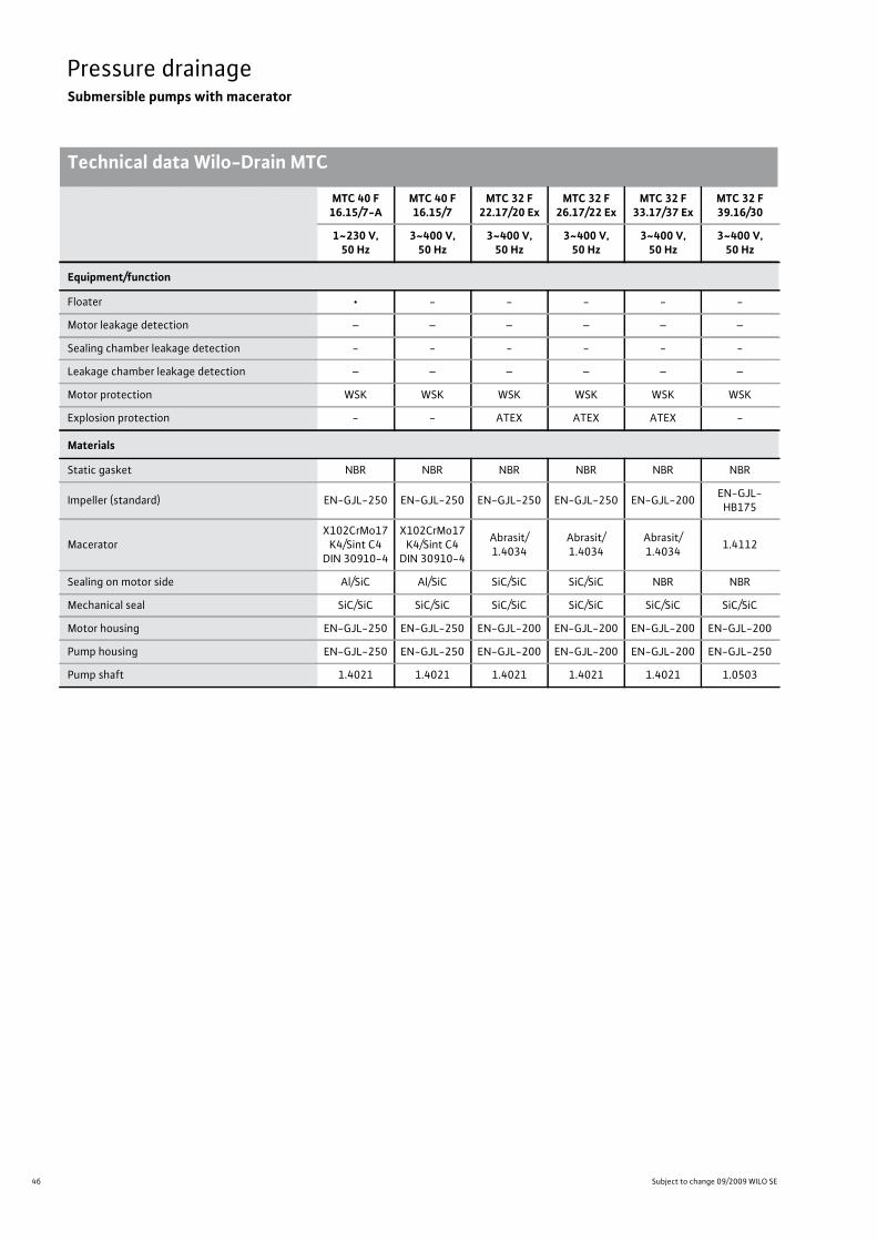
MTC 40 F 16.15/7-A
MTC 40 F 16.15/7
MTC 32 F 22.17/20 Ex
MTC 32 F 26.17/22 Ex
MTC 32 F 33.17/37 Ex
MTC 32 F 39.16/30
1~230 V, 50 Hz
3~400 V, 50 Hz
3~400 V, 50 Hz
3~400 V, 50 Hz
3~400 V, 50 Hz
3~400 V, 50 Hz
Equipment/function
Floater • - - - - -
Motor leakage detection – – – – – –
Sealing chamber leakage detection - - - - - -
Leakage chamber leakage detection – – – – – –
Motor protection WSK WSK WSK WSK WSK WSK
Explosion protection - - ATEX ATEX ATEX -
Materials
Static gasket NBR NBR NBR NBR NBR NBR
Impeller (standard) EN-GJL-250 EN-GJL-250 EN-GJL-250 EN-GJL-250 EN-GJL-200 EN-GJL-HB175
MaceratorX102CrMo17
K4/Sint C4 DIN 30910-4
X102CrMo17K4/Sint C4
DIN 30910-4
Abrasit/1.4034
Abrasit/1.4034
Abrasit/1.4034 1.4112
Sealing on motor side Al/SiC Al/SiC SiC/SiC SiC/SiC NBR NBR
Mechanical seal SiC/SiC SiC/SiC SiC/SiC SiC/SiC SiC/SiC SiC/SiC
Motor housing EN-GJL-250 EN-GJL-250 EN-GJL-200 EN-GJL-200 EN-GJL-200 EN-GJL-200
Pump housing EN-GJL-250 EN-GJL-250 EN-GJL-200 EN-GJL-200 EN-GJL-200 EN-GJL-250
Pump shaft 1.4021 1.4021 1.4021 1.4021 1.4021 1.0503

47
Pressure drainageSubmersible pumps with macerator
Wilo catalogue C 3.1 - 50 Hz – Pumps stations and solids separation system
Technical data Wilo-Drain MTC
Pressure
drainage
Pressure drainage Submersible pumps with macerator Technical data Wilo-Drain MTC Subject to change 09/2009 WILO SE Wilo catalogue C 3.1 - 50 Hz – Pumps stations and solids separation system
MTC 32 F 39.16/30 Ex
MTC 32 F 49.17/66
MTC 32 F 49.17/66 Ex
MTC 32 F 55.13/66
MTC 32 F 55.13/66 Ex
3~400 V, 50 Hz 3~400 V, 50 Hz 3~400 V, 50 Hz 3~400 V, 50 Hz 3~400 V, 50 Hz
Equipment/function
Floater - - - - -
Motor leakage detection – – – – –
Sealing chamber leakage detection - - - - -
Leakage chamber leakage detection – – – – –
Motor protection WSK WSK WSK WSK WSK
Explosion protection ATEX - ATEX - ATEX
Materials
Static gasket NBR NBR NBR NBR NBR
Impeller (standard) EN-GJL-HB175 EN-GJS-700-2 EN-GJS-700-2 EN-GJS-700-2 EN-GJS-700-2
Macerator 1.4112 1.4112 1.4112 1.4112 1.4112
Sealing on motor side NBR Carbon/ceramic Carbon/ceramic Carbon/ceramic Carbon/ceramic
Mechanical seal SiC/SiC SiC/SiC SiC/SiC SiC/SiC SiC/SiC
Motor housing EN-GJL-200 EN-GJL-200 EN-GJL-200 EN-GJL-200 EN-GJL-200
Pump housing EN-GJL-250 EN-GJL-250 EN-GJL-250 EN-GJL-250 EN-GJL-250
Pump shaft 1.0503 1.7225 1.7225 1.7225 1.7225
48 Subject to change 09/2009 WILO SE
Pressure drainageSubmersible pumps with macerator
Pump curves, ordering information Wilo-Drain MTC 40, MTC 32
Pressure drainage Submersible pumps with macerator Pump curves, ordering information Wilo-Drain MTC 40, MTC 32 Subject to change 09/2009 WILO SE Wilo catalogue C 3.1 - 50 Hz – Pumps stations and solids separation system
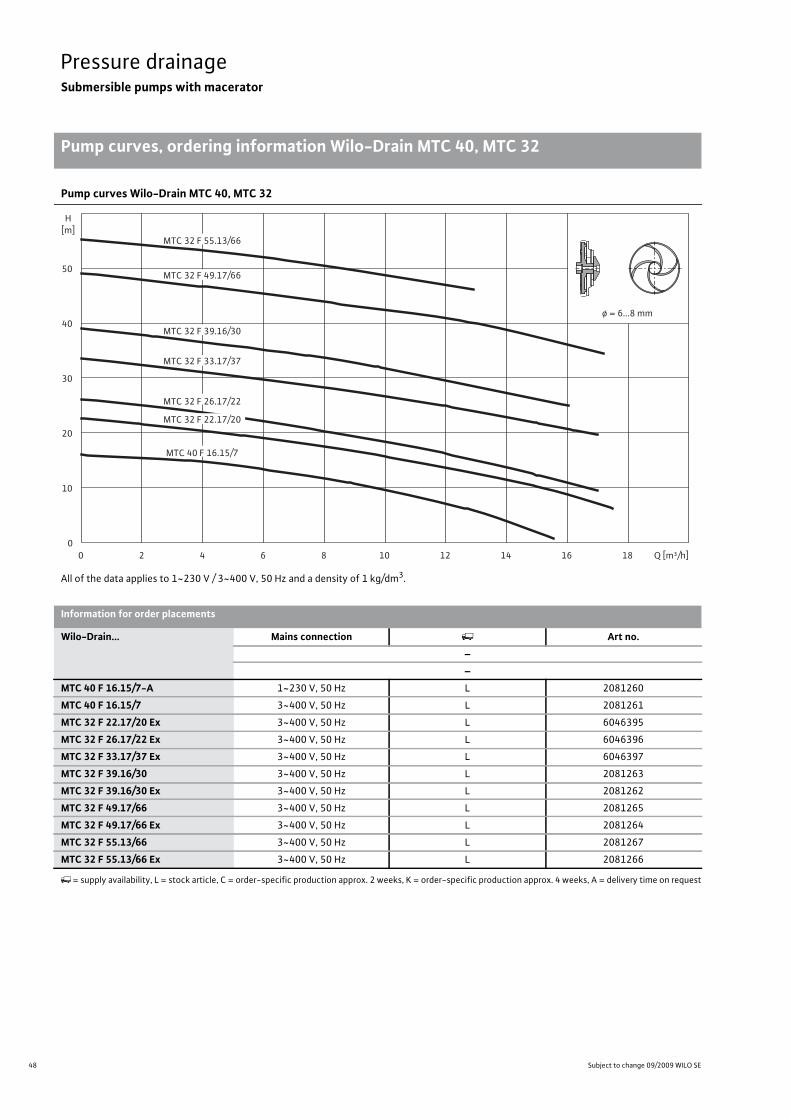
Pump curves Wilo-Drain MTC 40, MTC 32
All of the data applies to 1~230 V / 3~400 V, 50 Hz and a density of 1 kg/dm3.
0
10
20
30
40
50
H[m]
0 2 4 6 8 10 12 14 16 18 Q [m³/h]
ø = 6...8 mm
MTC 32 F 55.13/66
MTC 32 F 49.17/66
MTC 32 F 33.17/37
MTC 32 F 26.17/22
MTC 32 F 22.17/20
MTC 40 F 16.15/7
MTC 32 F 39.16/30
Information for order placements
Wilo-Drain... Mains connection Art no.––
MTC 40 F 16.15/7-A 1~230 V, 50 Hz L 2081260
MTC 40 F 16.15/7 3~400 V, 50 Hz L 2081261
MTC 32 F 22.17/20 Ex 3~400 V, 50 Hz L 6046395
MTC 32 F 26.17/22 Ex 3~400 V, 50 Hz L 6046396
MTC 32 F 33.17/37 Ex 3~400 V, 50 Hz L 6046397
MTC 32 F 39.16/30 3~400 V, 50 Hz L 2081263
MTC 32 F 39.16/30 Ex 3~400 V, 50 Hz L 2081262
MTC 32 F 49.17/66 3~400 V, 50 Hz L 2081265
MTC 32 F 49.17/66 Ex 3~400 V, 50 Hz L 2081264
MTC 32 F 55.13/66 3~400 V, 50 Hz L 2081267
MTC 32 F 55.13/66 Ex 3~400 V, 50 Hz L 2081266
�= supply availability, L = stock article, C = order-specific production approx. 2 weeks, K = order-specific production approx. 4 weeks, A = delivery time on request
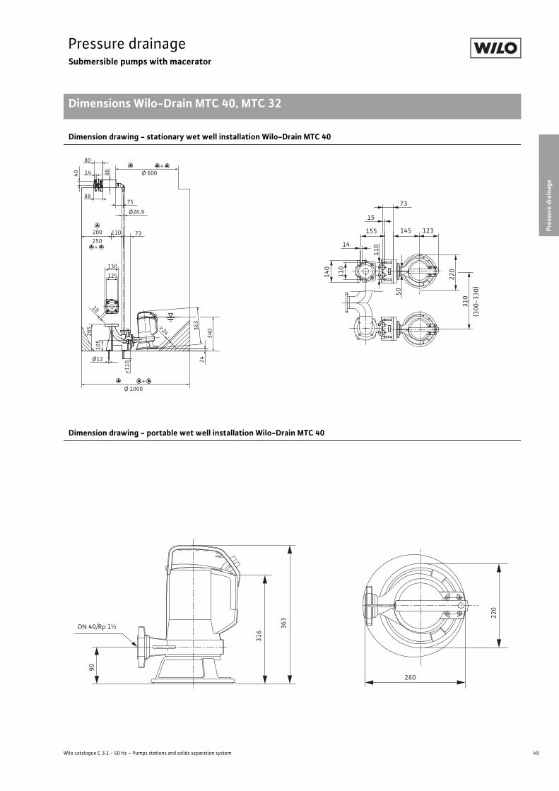
49
Pressure drainageSubmersible pumps with macerator
Pressure
drainage
Dimensions Wilo-Drain MTC 40, MTC 32
Wilo catalogue C 3.1 - 50 Hz – Pumps stations and solids separation system
Pressure drainage Submersible pumps with macerator Dimensions Wilo-Drain MTC 40, MTC 32 Subject to change 09/2009 WILO SE Wilo catalogue C 3.1 - 50 Hz – Pumps stations and solids separation system
Dimension drawing - stationary wet well installation Wilo-Drain MTC 40
Dimension drawing - portable wet well installation Wilo-Drain MTC 40
80
8875
110 73
801440
Ø12
105
265
18
125
130
> 110
>24
Ø 600
Ø26,9
+
Ø 1000+
250200
+
363
2434
0
310
(300
-330
)
15
155
11014
110
140
220
50
123145
73
363 22
0
90
316
DN 40/Rp 1½
260

50 Subject to change 09/2009 WILO SE
Pressure drainageSubmersible pumps with macerator
Dimensions Wilo-Drain MTC 40, MTC 32
Pressure drainage Submersible pumps with macerator Dimensions Wilo-Drain MTC 40, MTC 32 Subject to change 09/2009 WILO SE Wilo catalogue C 3.1 - 50 Hz – Pumps stations and solids separation system
Dimension drawing Wilo-Drain MTC 32 F22 - F33
B
33
319
95
G2
120 26
0
109
G4125
DN 32
E
54F
43
80
18
120
80
90
625
DN 36
DH
A
310
C
Dimensions
Wilo-Drain... DimensionsA B C D E F H
[mm]MTC 32 F 22.17/20 Ex 211 379 221 120 338 17 252
MTC 32 F 26.17/22 Ex 211 379 221 120 338 17 252
MTC 32 F 33.17/37 Ex 197 394 224 140 378 20 279

51
Pressure drainageSubmersible pumps with macerator
Pressure
drainage
Dimensions Wilo-Drain MTC 40, MTC 32
Wilo catalogue C 3.1 - 50 Hz – Pumps stations and solids separation system
Pressure drainage Submersible pumps with macerator Dimensions Wilo-Drain MTC 40, MTC 32 Subject to change 09/2009 WILO SE Wilo catalogue C 3.1 - 50 Hz – Pumps stations and solids separation system
Dimension drawing Wilo-Drain MTC 32 F39 - F55
I
JK
L
G
260
F
5540 1“
2“ 15
145
3xØ12
220
95
95
R ca.150
min. 20
E
D
C
DN32
H
B A
Dimensions
Wilo-Drain... DimensionsA B C D E F G H I J K L
[mm]MTC 32 F 39.16/30 140 180 330 350 490 450 125 520 125 420 540 635
MTC 32 F 39.16/30 Ex 140 180 330 350 490 450 125 520 125 420 540 635
MTC 32 F 49.17/66 150 210 430 400 625 525 140 665 155 500 615 705
MTC 32 F 49.17/66 Ex 150 210 430 400 625 525 140 665 155 500 615 705
MTC 32 F 55.13/66 150 210 430 400 625 525 140 665 155 500 615 705
MTC 32 F 55.13/66 Ex 150 210 430 400 625 525 140 665 155 500 615 705
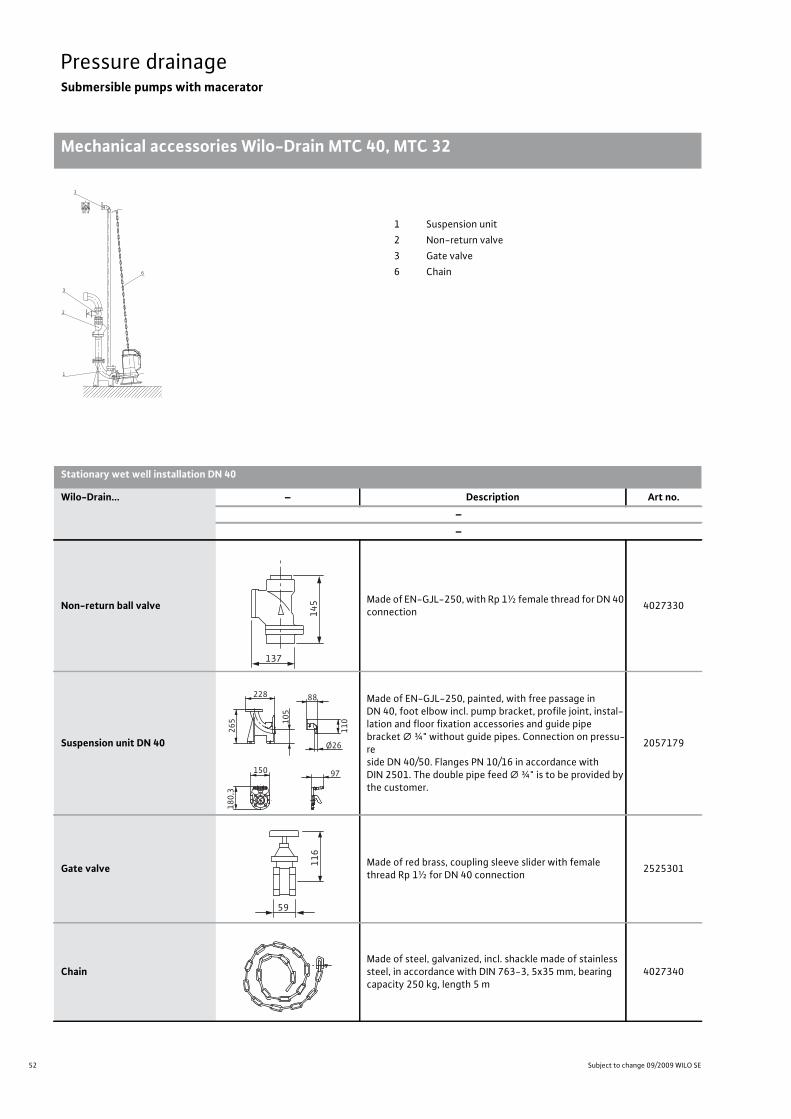
52 Subject to change 09/2009 WILO SE
Pressure drainageSubmersible pumps with macerator
Mechanical accessories Wilo-Drain MTC 40, MTC 32
Pressure drainage Submersible pumps with macerator Mechanical accessories Wilo-Drain MTC 40, MTC 32 Subject to change 09/2009 WILO SE Wilo catalogue C 3.1 - 50 Hz – Pumps stations and solids separation system
1
3
2
1
6
1 Suspension unit2 Non-return valve3 Gate valve6 Chain
Stationary wet well installation DN 40
Wilo-Drain... – Description Art no.––
Non-return ball valve Made of EN-GJL-250, with Rp 1½ female thread for DN 40 connection 4027330
Suspension unit DN 40
Made of EN-GJL-250, painted, with free passage in DN 40, foot elbow incl. pump bracket, profile joint, instal-lation and floor fixation accessories and guide pipe bracket � ¾" without guide pipes. Connection on pressu-re side DN 40/50. Flanges PN 10/16 in accordance with DIN 2501. The double pipe feed � ¾" is to be provided by the customer.
2057179
Gate valve Made of red brass, coupling sleeve slider with female thread Rp 1½ for DN 40 connection 2525301
ChainMade of steel, galvanized, incl. shackle made of stainless steel, in accordance with DIN 763-3, 5x35 mm, bearing capacity 250 kg, length 5 m
4027340
145
137
105
228
265
88
110
Ø26
150
180,3
97
116
59
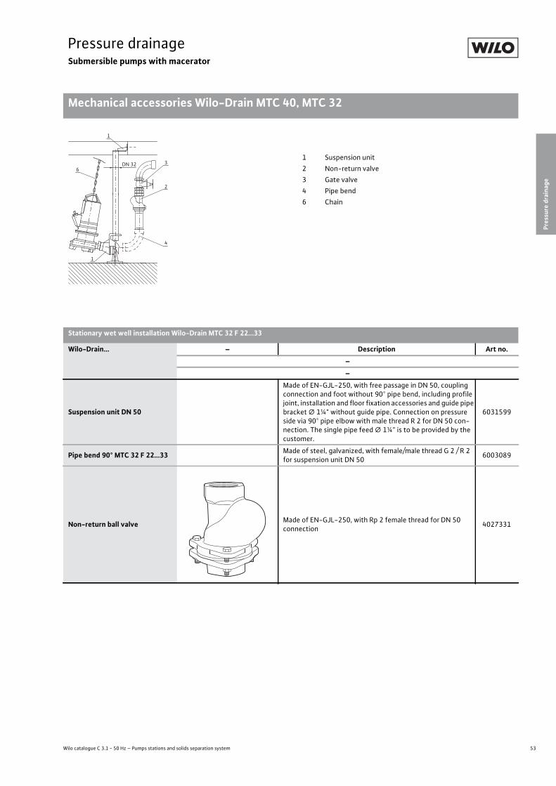
53
Pressure drainageSubmersible pumps with macerator
Pressure
drainage
Mechanical accessories Wilo-Drain MTC 40, MTC 32
Wilo catalogue C 3.1 - 50 Hz – Pumps stations and solids separation system
Pressure drainage Submersible pumps with macerator Mechanical accessories Wilo-Drain MTC 40, MTC 32 Subject to change 09/2009 WILO SE Wilo catalogue C 3.1 - 50 Hz – Pumps stations and solids separation system
DN 32 3
2
4
6
1
1
1 Suspension unit2 Non-return valve3 Gate valve4 Pipe bend6 Chain
Stationary wet well installation Wilo-Drain MTC 32 F 22...33
Wilo-Drain... – Description Art no.––
Suspension unit DN 50
Made of EN-GJL-250, with free passage in DN 50, coupling connection and foot without 90° pipe bend, including profile joint, installation and floor fixation accessories and guide pipe bracket � 1¼" without guide pipe. Connection on pressure side via 90° pipe elbow with male thread R 2 for DN 50 con-nection. The single pipe feed � 1¼" is to be provided by the customer.
6031599
Pipe bend 90° MTC 32 F 22...33 Made of steel, galvanized, with female/male thread G 2 / R 2 for suspension unit DN 50 6003089
Non-return ball valve Made of EN-GJL-250, with Rp 2 female thread for DN 50 connection 4027331

54 Subject to change 09/2009 WILO SE
Pressure drainageSubmersible pumps with macerator
Mechanical accessories Wilo-Drain MTC 40, MTC 32
Shut-off ball cock Made of brass, nickel-plated, with Rp 2 female thread for DN 50 connection 4027338
ChainMade of steel, galvanized, incl. shackle made of stainless steel, in accordance with DIN 763-3, 5x35 mm, bearing capa-city 250 kg, length 5 m
4027340
Stationary wet well installation Wilo-Drain MTC 32 F 22...33
Wilo-Drain... – Description Art no.––
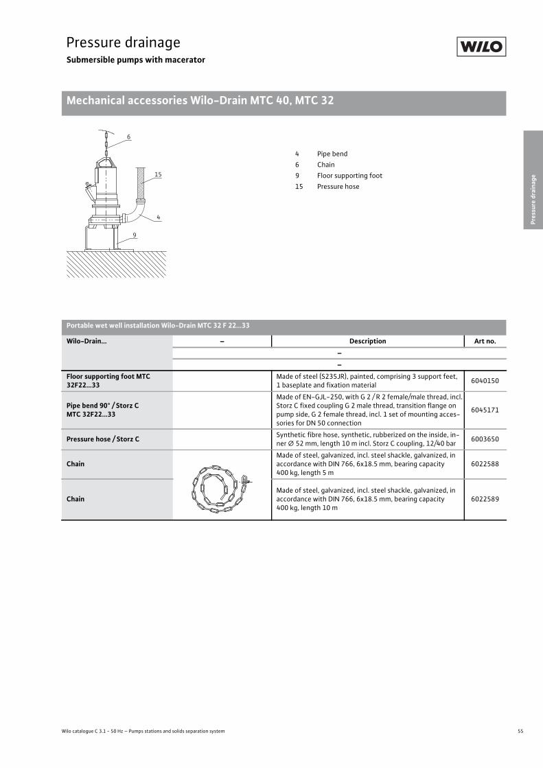
55
Pressure drainageSubmersible pumps with macerator
Pressure
drainage
Mechanical accessories Wilo-Drain MTC 40, MTC 32
Wilo catalogue C 3.1 - 50 Hz – Pumps stations and solids separation system
Pressure drainage Submersible pumps with macerator Mechanical accessories Wilo-Drain MTC 40, MTC 32 Subject to change 09/2009 WILO SE Wilo catalogue C 3.1 - 50 Hz – Pumps stations and solids separation system
6
15
4
9
4 Pipe bend6 Chain9 Floor supporting foot15 Pressure hose
Portable wet well installation Wilo-Drain MTC 32 F 22...33
Wilo-Drain... – Description Art no.––
Floor supporting foot MTC 32F22...33
Made of steel (S235JR), painted, comprising 3 support feet, 1 baseplate and fixation material 6040150
Pipe bend 90° / Storz CMTC 32F22...33
Made of EN-GJL-250, with G 2 / R 2 female/male thread, incl. Storz C fixed coupling G 2 male thread, transition flange on pump side, G 2 female thread, incl. 1 set of mounting acces-sories for DN 50 connection
6045171
Pressure hose / Storz C Synthetic fibre hose, synthetic, rubberized on the inside, in-ner � 52 mm, length 10 m incl. Storz C coupling, 12/40 bar 6003650
ChainMade of steel, galvanized, incl. steel shackle, galvanized, in accordance with DIN 766, 6x18.5 mm, bearing capacity 400 kg, length 5 m
6022588
ChainMade of steel, galvanized, incl. steel shackle, galvanized, in accordance with DIN 766, 6x18.5 mm, bearing capacity 400 kg, length 10 m
6022589

56 Subject to change 09/2009 WILO SE
Pressure drainageSubmersible pumps with macerator
Mechanical accessories Wilo-Drain MTC 40, MTC 32
Pressure drainage Submersible pumps with macerator Mechanical accessories Wilo-Drain MTC 40, MTC 32 Subject to change 09/2009 WILO SE Wilo catalogue C 3.1 - 50 Hz – Pumps stations and solids separation system
6
3
2
1
11 Suspension unit2 Non-return valve3 Gate valve6 Chain
Stationary wet well installation Wilo-Drain MTC 32 F 39...55
Wilo-Drain... – Description Art no.––
Suspension unit Rp 1½
Made of EN-GJL-250, painted, with free passage in DN 40, foot elbow including pump holder, profile joint, installation and floor fixation accessories and guide pipe bracket � 1" without guide pipes. Connection on pressure side DN 40. Flanges PN 10/16 in accordance with DIN 2501. The single pipe feed � 1" is to be provided by the customer.
2082630
Centre of gravity extension Shackle adapter with fixation accessories for MTC 32 F 49 and MTC 32 F 55 pumps 6042181
Non-return ball valve Made of EN-GJL-250, with Rp 1½ female thread for DN 40 connection 4027330
145
3xØ12
220
9514
5
137

57
Pressure drainageSubmersible pumps with macerator
Pressure
drainage
Mechanical accessories Wilo-Drain MTC 40, MTC 32
Wilo catalogue C 3.1 - 50 Hz – Pumps stations and solids separation system
Gate valve Made of red brass, coupling sleeve slider with female thread Rp 1½ for DN 40 connection 2525301
ChainMade of steel, galvanized, incl. shackle made of stainless steel, in accordance with DIN 763-3, 5x35 mm, bearing capa-city 250 kg, length 5 m
4027340
Stationary wet well installation Wilo-Drain MTC 32 F 39...55
Wilo-Drain... – Description Art no.––
116
59
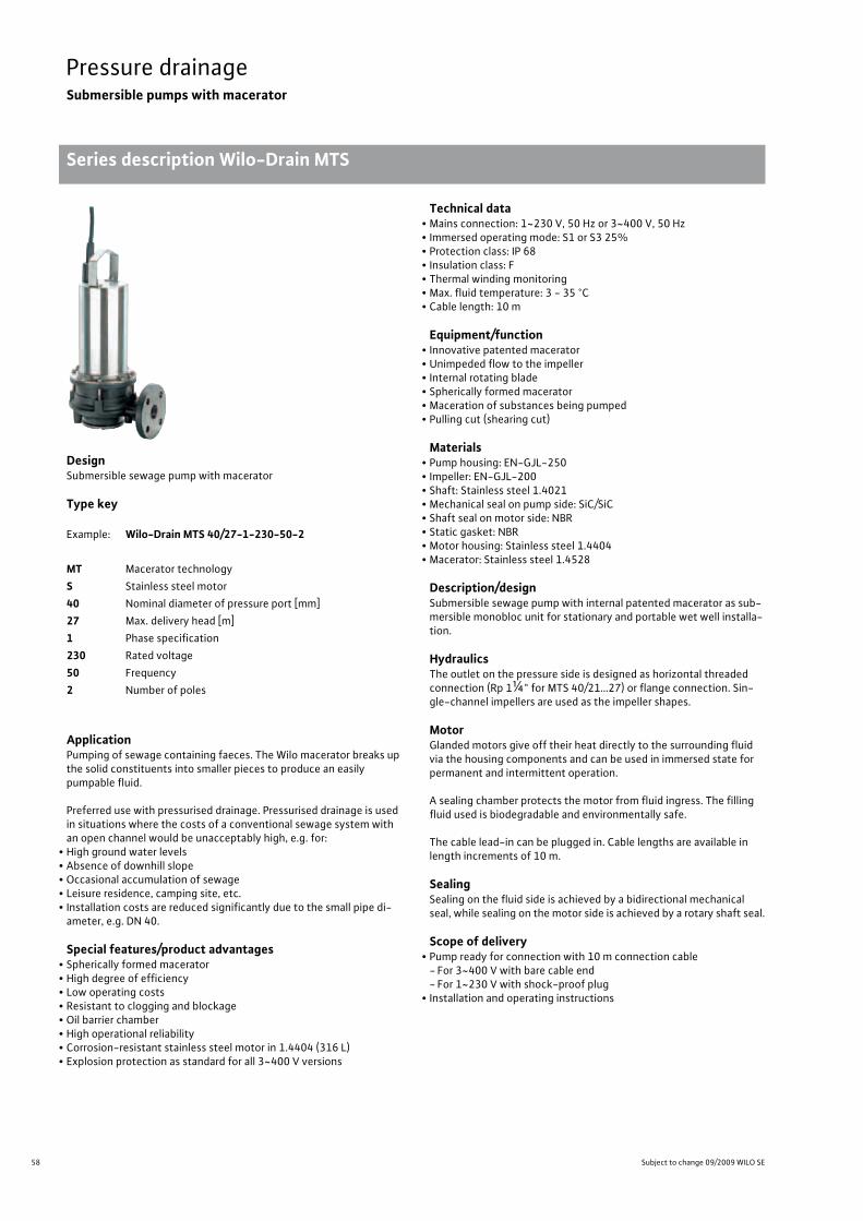
58 Subject to change 09/2009 WILO SE
Pressure drainageSubmersible pumps with macerator
Series description Wilo-Drain MTS
Pressure drainage Submersible pumps with macerator Series description Wilo-Drain MTS Subject to change 09/2009 WILO SE Wilo catalogue C 3.1 - 50 Hz – Pumps stations and solids separation system
DesignSubmersible sewage pump with macerator
Type key
ApplicationPumping of sewage containing faeces. The Wilo macerator breaks up the solid constituents into smaller pieces to produce an easily pumpable fluid.
Preferred use with pressurised drainage. Pressurised drainage is used in situations where the costs of a conventional sewage system with an open channel would be unacceptably high, e.g. for:
• High ground water levels• Absence of downhill slope• Occasional accumulation of sewage• Leisure residence, camping site, etc.• Installation costs are reduced significantly due to the small pipe di-ameter, e.g. DN 40.
Special features/product advantages• Spherically formed macerator• High degree of efficiency• Low operating costs• Resistant to clogging and blockage• Oil barrier chamber• High operational reliability• Corrosion-resistant stainless steel motor in 1.4404 (316 L)• Explosion protection as standard for all 3~400 V versions
Technical data• Mains connection: 1~230 V, 50 Hz or 3~400 V, 50 Hz• Immersed operating mode: S1 or S3 25%• Protection class: IP 68• Insulation class: F• Thermal winding monitoring• Max. fluid temperature: 3 - 35 °C• Cable length: 10 m
Equipment/function• Innovative patented macerator• Unimpeded flow to the impeller• Internal rotating blade• Spherically formed macerator• Maceration of substances being pumped• Pulling cut (shearing cut)
Materials• Pump housing: EN-GJL-250• Impeller: EN-GJL-200• Shaft: Stainless steel 1.4021• Mechanical seal on pump side: SiC/SiC• Shaft seal on motor side: NBR• Static gasket: NBR• Motor housing: Stainless steel 1.4404• Macerator: Stainless steel 1.4528
Description/designSubmersible sewage pump with internal patented macerator as sub-mersible monobloc unit for stationary and portable wet well installa-tion.
HydraulicsThe outlet on the pressure side is designed as horizontal threaded connection (Rp 1¼" for MTS 40/21…27) or flange connection. Sin-gle-channel impellers are used as the impeller shapes.
MotorGlanded motors give off their heat directly to the surrounding fluid via the housing components and can be used in immersed state for permanent and intermittent operation.
A sealing chamber protects the motor from fluid ingress. The filling fluid used is biodegradable and environmentally safe.
The cable lead-in can be plugged in. Cable lengths are available in length increments of 10 m.
SealingSealing on the fluid side is achieved by a bidirectional mechanical seal, while sealing on the motor side is achieved by a rotary shaft seal.
Scope of delivery• Pump ready for connection with 10 m connection cable- For 3~400 V with bare cable end- For 1~230 V with shock-proof plug
• Installation and operating instructions
Example: Wilo-Drain MTS 40/27-1-230-50-2
MT Macerator technologyS Stainless steel motor40 Nominal diameter of pressure port [mm]27 Max. delivery head [m]1 Phase specification230 Rated voltage50 Frequency2 Number of poles
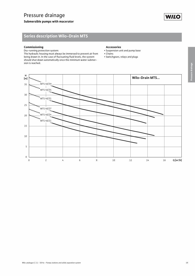
59
Pressure drainageSubmersible pumps with macerator
Pressure
drainage
Series description Wilo-Drain MTS
Wilo catalogue C 3.1 - 50 Hz – Pumps stations and solids separation system
CommissioningDry-running protection system:The hydraulic housing must always be immersed to prevent air from being drawn in. In the case of fluctuating fluid levels, the system should shut down automatically once the minimum water submer-sion is reached.
Accessories• Suspension unit and pump base• Chains• Switchgears, relays and plugs
0
25
15
20
10
5
H[m]
35
30
80 4 10 12 16 Q [m³/h]1462
Wilo-Drain MTS...MTS 40/39
MTS 40/35
MTS 40/31
MTS 40/27
MTS 40/24
MTS 40/21
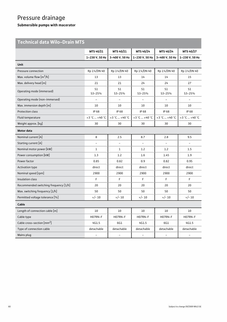
60 Subject to change 09/2009 WILO SE
Pressure drainageSubmersible pumps with macerator
Technical data Wilo-Drain MTSPressure drainage Submersible pumps with macerator Technical data Wilo-Drain MTS Subject to change 09/2009 WILO SE Wilo catalogue C 3.1 - 50 Hz – Pumps stations and solids separation system
MTS 40/21 MTS 40/21 MTS 40/24 MTS 40/24 MTS 40/27
1~230 V, 50 Hz 3~400 V, 50 Hz 1~230 V, 50 Hz 3~400 V, 50 Hz 1~230 V, 50 Hz
Unit
Pressure connection Rp 1¼/DN 40 Rp 1¼/DN 40 Rp 1¼/DN 40 Rp 1¼/DN 40 Rp 1¼/DN 40
Max. volume flow [m3/h] 13 13 14 14 15
Max. delivery head [m] 21 21 24 24 27
Operating mode (immersed)S1
S3-25%S1
S3-25%S1
S3-25%S1
S3-25%S1
S3-25%
Operating mode (non-immersed) - - - - -
Max. immersion depth [m] 10 10 10 10 10
Protection class IP 68 IP 68 IP 68 IP 68 IP 68
Fluid temperature +3 °C ... +40 °C +3 °C ... +40 °C +3 °C ... +40 °C +3 °C ... +40 °C +3 °C ... +40 °C
Weight approx. [kg] 30 30 30 30 30
Motor data
Nominal current [A] 8 2.5 8.7 2.8 9.5
Starting current [A] - - - - -
Nominal motor power [kW] 1 1 1.2 1.2 1.5
Power consumption [kW] 1.3 1.2 1.6 1.45 1.9
Power factor 0.85 0.82 0.9 0.82 0.95
Activation type direct direct direct direct direct
Nominal speed [rpm] 2900 2900 2900 2900 2900
Insulation class F F F F F
Recommended switching frequency [1/h] 20 20 20 20 20
Max. switching frequency [1/h] 50 50 50 50 50
Permitted voltage tolerance [%] +/- 10 +/- 10 +/- 10 +/- 10 +/- 10
Cable
Length of connection cable [m] 10 10 10 10 10
Cable type H07RN-F H07RN-F H07RN-F H07RN-F H07RN-F
Cable cross-section [mm2] 4G1.5 6G1 4G1.5 6G1 4G1.5
Type of connection cable detachable detachable detachable detachable detachable
Mains plug - - - - -

61
Pressure drainageSubmersible pumps with macerator
Wilo catalogue C 3.1 - 50 Hz – Pumps stations and solids separation system
Technical data Wilo-Drain MTS
Pressure
drainage
Pressure drainage Submersible pumps with macerator Technical data Wilo-Drain MTS Subject to change 09/2009 WILO SE Wilo catalogue C 3.1 - 50 Hz – Pumps stations and solids separation system
MTS 40/27 MTS 40/31 MTS 40/35 MTS 40/39
3~400 V, 50 Hz 3~400 V, 50 Hz 3~400 V, 50 Hz 3~400 V, 50 Hz
Unit
Pressure connection Rp 1¼/DN 40 DN 40 DN 40 DN 40
Max. volume flow [m3/h] 15 14 15 16
Max. delivery head [m] 27 31 35 39
Operating mode (immersed)S1
S3-25%S1
S3-25%S1
S3-25%S1
S3-25%
Operating mode (non-immersed) - - - -
Max. immersion depth [m] 10 10 10 10
Protection class IP 68 IP 68 IP 68 IP 68
Fluid temperature +3 °C ... +40 °C +3 °C ... +40 °C +3 °C ... +40 °C +3 °C ... +40 °C
Weight approx. [kg] 30 30 30 30
Motor data
Nominal current [A] 3.2 5.3 5.8 6
Starting current [A] - - - -
Nominal motor power [kW] 1.5 2.1 2.3 2.5
Power consumption [kW] 1.7 2.6 2.8 3
Power factor 0.82 0.77 0.78 0.8
Activation type direct direct direct direct
Nominal speed [rpm] 2900 2900 2900 2900
Insulation class F F F F
Recommended switching frequency [1/h] 20 20 20 20
Max. switching frequency [1/h] 50 50 50 50
Permitted voltage tolerance [%] +/- 10 +/- 10 +/- 10 +/- 10
Cable
Length of connection cable [m] 10 10 10 10
Cable type H07RN-F H07RN-F H07RN-F H07RN-F
Cable cross-section [mm2] 6G1 6G1 6G1 6G1
Type of connection cable detachable detachable detachable detachable
Mains plug - - - -

62 Subject to change 09/2009 WILO SE
Pressure drainageSubmersible pumps with macerator
Technical data Wilo-Drain MTSPressure drainage Submersible pumps with macerator Technical data Wilo-Drain MTS Subject to change 09/2009 WILO SE Wilo catalogue C 3.1 - 50 Hz – Pumps stations and solids separation system
MTS 40/21 MTS 40/21 MTS 40/24 MTS 40/24 MTS 40/27
1~230 V, 50 Hz 3~400 V, 50 Hz 1~230 V, 50 Hz 3~400 V, 50 Hz 1~230 V, 50 Hz
Equipment/function
Floater - - - - -
Motor leakage detection – – – – –
Sealing chamber leakage detection - - - - -
Leakage chamber leakage detection – – – – –
Motor protection WSK WSK WSK WSK WSK
Explosion protection - ATEX - ATEX -
Materials
Static gasket NBR NBR NBR NBR NBR
Impeller (standard) EN-GJL-250 EN-GJL-250 EN-GJL-250 EN-GJL-250 EN-GJL-250
Macerator 1.4528 1.4528 1.4528 1.4528 1.4528
Sealing on motor side NBR NBR NBR NBR NBR
Mechanical seal SiC/SiC SiC/SiC SiC/SiC SiC/SiC SiC/SiC
Motor housing 1.4404 1.4404 1.4404 1.4404 1.4404
Pump housing EN-GJL-250 EN-GJL-250 EN-GJL-250 EN-GJL-250 EN-GJL-250
Pump shaft 1.4021 1.4021 1.4021 1.4021 1.4021
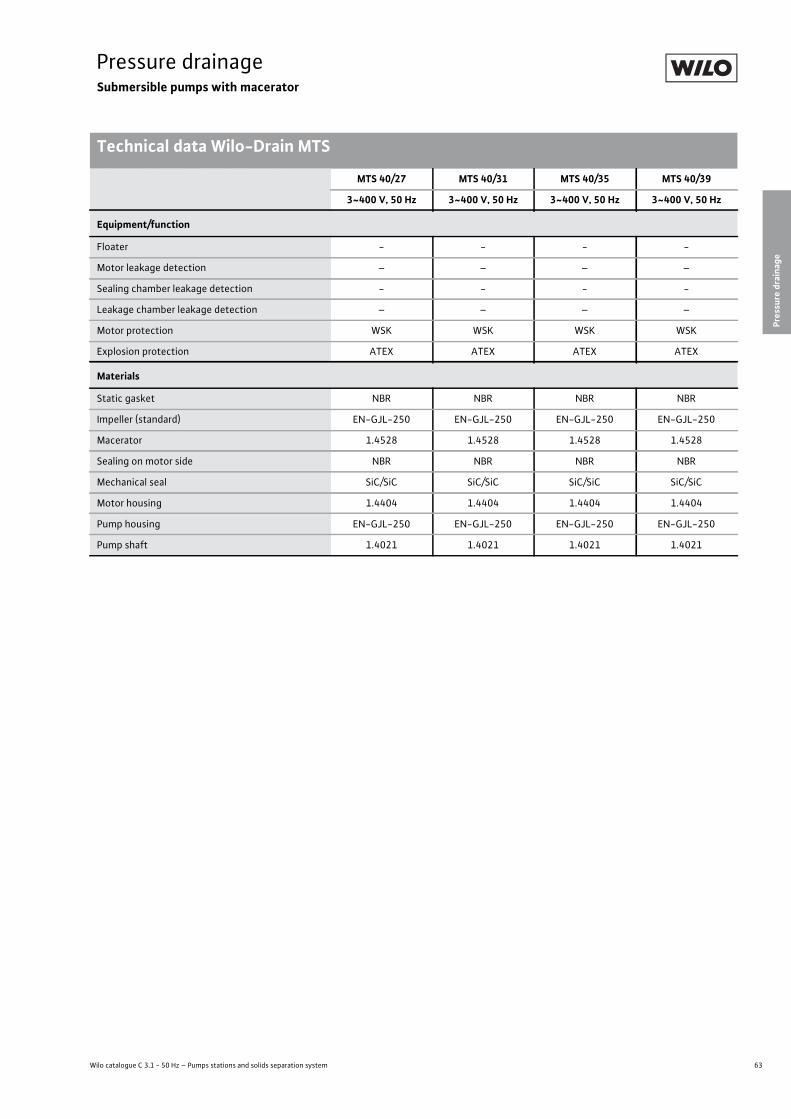
63
Pressure drainageSubmersible pumps with macerator
Wilo catalogue C 3.1 - 50 Hz – Pumps stations and solids separation system
Technical data Wilo-Drain MTS
Pressure
drainage
Pressure drainage Submersible pumps with macerator Technical data Wilo-Drain MTS Subject to change 09/2009 WILO SE Wilo catalogue C 3.1 - 50 Hz – Pumps stations and solids separation system
MTS 40/27 MTS 40/31 MTS 40/35 MTS 40/39
3~400 V, 50 Hz 3~400 V, 50 Hz 3~400 V, 50 Hz 3~400 V, 50 Hz
Equipment/function
Floater - - - -
Motor leakage detection – – – –
Sealing chamber leakage detection - - - -
Leakage chamber leakage detection – – – –
Motor protection WSK WSK WSK WSK
Explosion protection ATEX ATEX ATEX ATEX
Materials
Static gasket NBR NBR NBR NBR
Impeller (standard) EN-GJL-250 EN-GJL-250 EN-GJL-250 EN-GJL-250
Macerator 1.4528 1.4528 1.4528 1.4528
Sealing on motor side NBR NBR NBR NBR
Mechanical seal SiC/SiC SiC/SiC SiC/SiC SiC/SiC
Motor housing 1.4404 1.4404 1.4404 1.4404
Pump housing EN-GJL-250 EN-GJL-250 EN-GJL-250 EN-GJL-250
Pump shaft 1.4021 1.4021 1.4021 1.4021
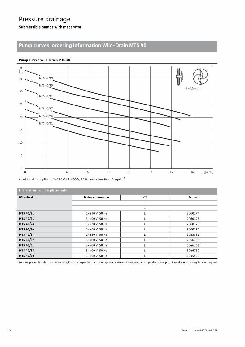
64 Subject to change 09/2009 WILO SE
Pressure drainageSubmersible pumps with macerator
Pump curves, ordering information Wilo-Drain MTS 40
Pressure drainage Submersible pumps with macerator Pump curves, ordering information Wilo-Drain MTS 40 Subject to change 09/2009 WILO SE Wilo catalogue C 3.1 - 50 Hz – Pumps stations and solids separation system
Pump curves Wilo-Drain MTS 40
All of the data applies to 1~230 V / 3~400 V, 50 Hz and a density of 1 kg/dm3.
0
25
15
20
10
5
H[m]
35
30
80 4 10 12 16 Q [m³/h]1462
ø = 10 mm
MTS 40/39
MTS 40/35
MTS 40/31
MTS 40/27
MTS 40/24
MTS 40/21
Information for order placements
Wilo-Drain... Mains connection Art no.––
MTS 40/21 1~230 V, 50 Hz L 2060174
MTS 40/21 3~400 V, 50 Hz L 2060176
MTS 40/24 1~230 V, 50 Hz L 2060170
MTS 40/24 3~400 V, 50 Hz L 2060175
MTS 40/27 1~230 V, 50 Hz L 2053831
MTS 40/27 3~400 V, 50 Hz L 2056253
MTS 40/31 3~400 V, 50 Hz L 6046761
MTS 40/35 3~400 V, 50 Hz L 6046760
MTS 40/39 3~400 V, 50 Hz L 6045558
�= supply availability, L = stock article, C = order-specific production approx. 2 weeks, K = order-specific production approx. 4 weeks, A = delivery time on request
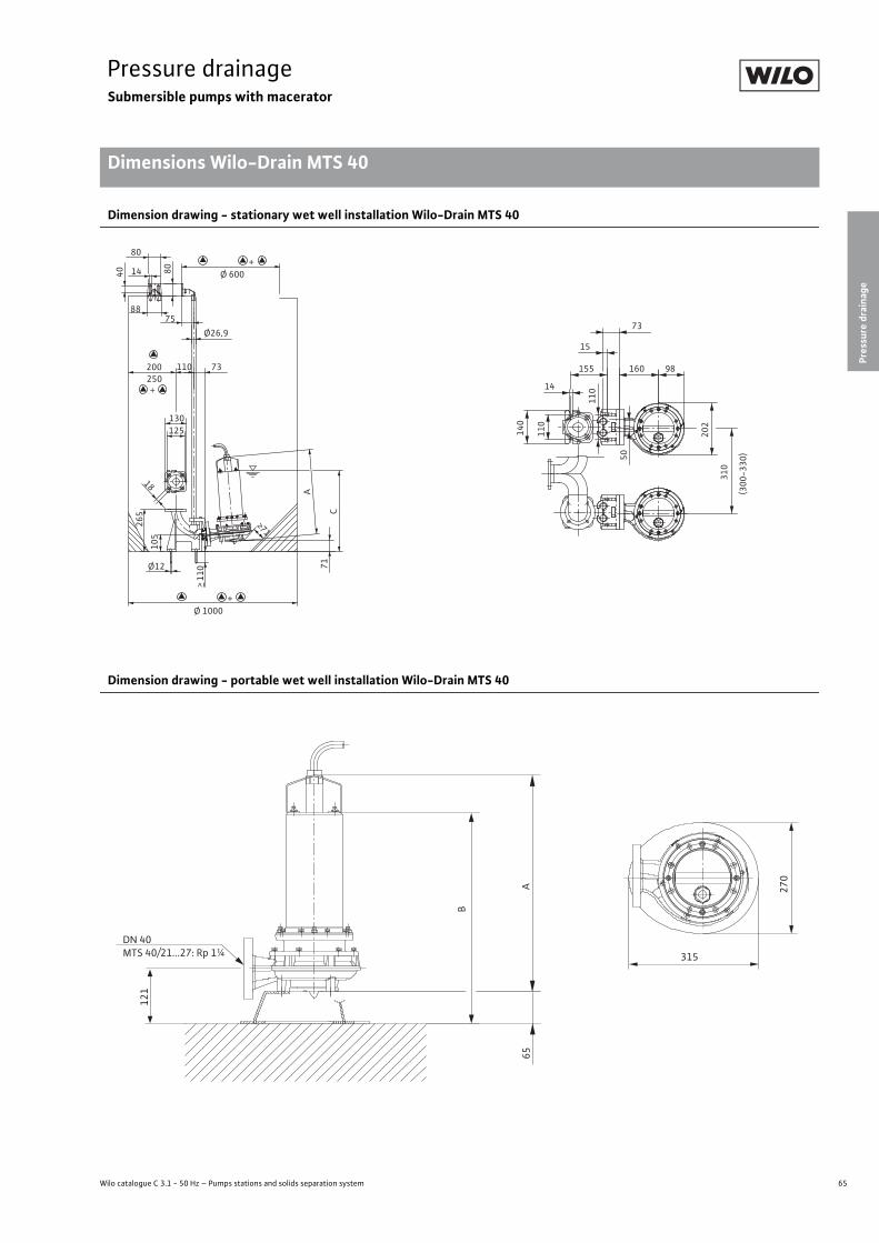
65
Pressure drainageSubmersible pumps with macerator
Pressure
drainage
Dimensions Wilo-Drain MTS 40
Wilo catalogue C 3.1 - 50 Hz – Pumps stations and solids separation system
Pressure drainage Submersible pumps with macerator Dimensions Wilo-Drain MTS 40 Subject to change 09/2009 WILO SE Wilo catalogue C 3.1 - 50 Hz – Pumps stations and solids separation system
Dimension drawing - stationary wet well installation Wilo-Drain MTS 40
Dimension drawing - portable wet well installation Wilo-Drain MTS 40
Ø12
> 11
0 7175
250200
Ø26,9
73110
125130
265 C
A
Ø 1000
Ø 600
>71
14
18
80
80
40
88
310
(300
-330
)
98160
73
15
155
11014
110
140
202
50
105
+
+
+
65A
121
270
315
B
DN 40MTS 40/21...27: Rp 1¼

66 Subject to change 09/2009 WILO SE
Pressure drainageSubmersible pumps with macerator
Dimensions Wilo-Drain MTS 40
Dimensions
Wilo-Drain... Mains connection Dimensions– A B C– [mm]
MTS 40/21 1~230 V, 50 Hz 498.5 463.5 469.5
MTS 40/21 3~400 V, 50 Hz 498.5 463.5 469.5
MTS 40/24 1~230 V, 50 Hz 498.5 463.5 469.5
MTS 40/24 3~400 V, 50 Hz 498.5 463.5 469.5
MTS 40/27 1~230 V, 50 Hz 498.5 463.5 469.5
MTS 40/27 3~400 V, 50 Hz 498.5 463.5 469.5
MTS 40/31 3~400 V, 50 Hz 518.5 483.5 489.5
MTS 40/35 3~400 V, 50 Hz 518.5 483.5 489.5
MTS 40/39 3~400 V, 50 Hz 518.5 483.5 489.5
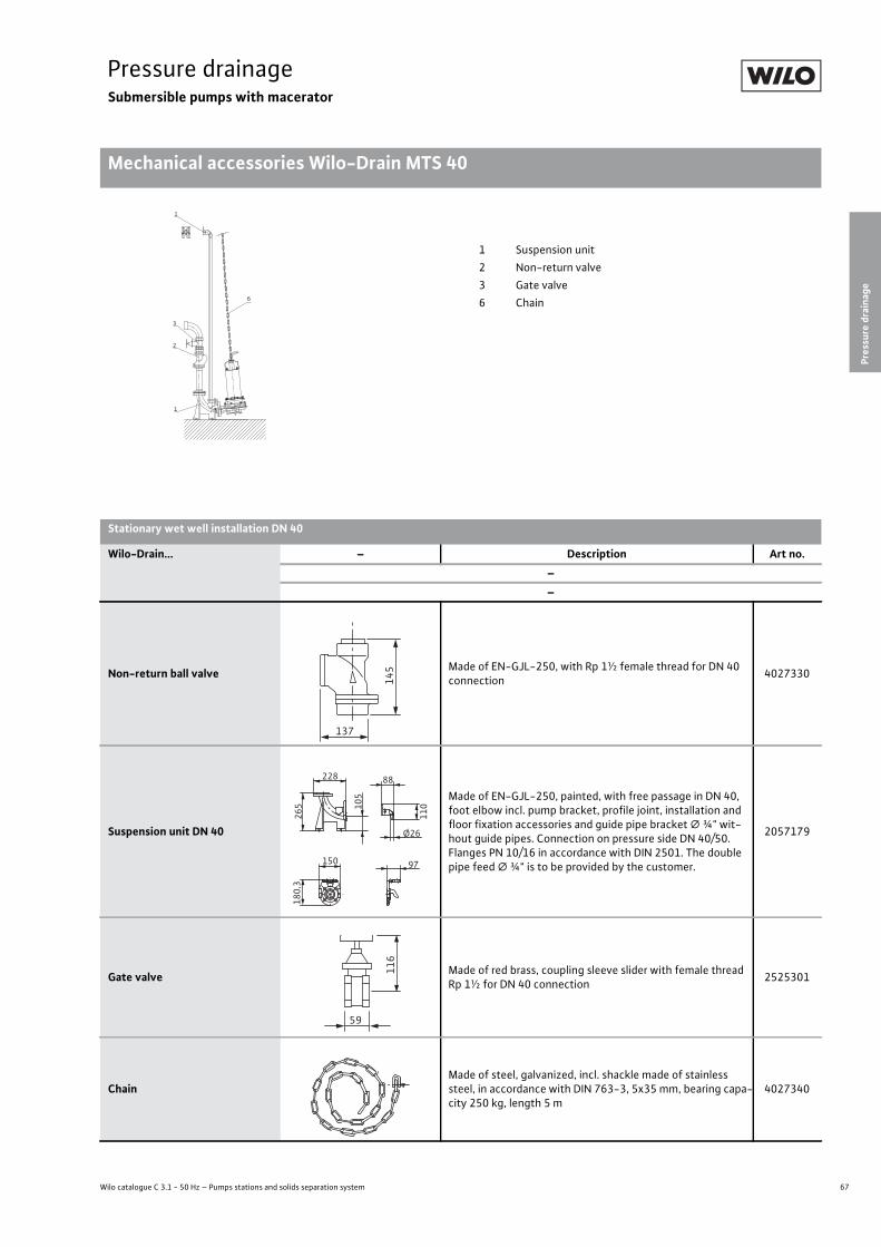
67
Pressure drainageSubmersible pumps with macerator
Pressure
drainage
Mechanical accessories Wilo-Drain MTS 40
Wilo catalogue C 3.1 - 50 Hz – Pumps stations and solids separation system
Pressure drainage Submersible pumps with macerator Mechanical accessories Wilo-Drain MTS 40 Subject to change 09/2009 WILO SE Wilo catalogue C 3.1 - 50 Hz – Pumps stations and solids separation system
1
3
2
1
6
1 Suspension unit2 Non-return valve3 Gate valve6 Chain
Stationary wet well installation DN 40
Wilo-Drain... – Description Art no.––
Non-return ball valve Made of EN-GJL-250, with Rp 1½ female thread for DN 40 connection 4027330
Suspension unit DN 40
Made of EN-GJL-250, painted, with free passage in DN 40, foot elbow incl. pump bracket, profile joint, installation and floor fixation accessories and guide pipe bracket � ¾" wit-hout guide pipes. Connection on pressure side DN 40/50. Flanges PN 10/16 in accordance with DIN 2501. The double pipe feed � ¾" is to be provided by the customer.
2057179
Gate valve Made of red brass, coupling sleeve slider with female thread Rp 1½ for DN 40 connection 2525301
ChainMade of steel, galvanized, incl. shackle made of stainless steel, in accordance with DIN 763-3, 5x35 mm, bearing capa-city 250 kg, length 5 m
4027340
145
137
105
228
265
88
110
Ø26
150
180,3
97
116
59
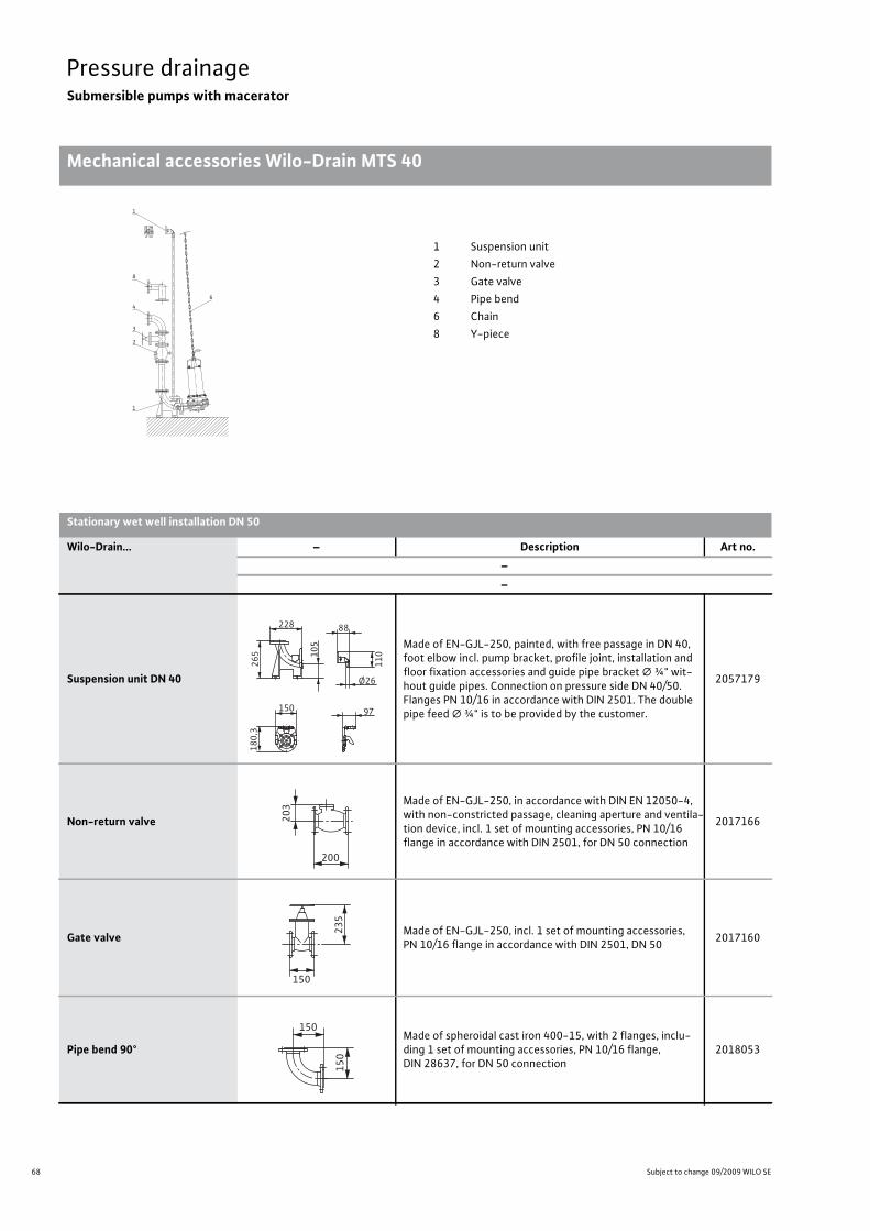
68 Subject to change 09/2009 WILO SE
Pressure drainageSubmersible pumps with macerator
Mechanical accessories Wilo-Drain MTS 40
Pressure drainage Submersible pumps with macerator Mechanical accessories Wilo-Drain MTS 40 Subject to change 09/2009 WILO SE Wilo catalogue C 3.1 - 50 Hz – Pumps stations and solids separation system
1
3
2
4
1
8
6
1 Suspension unit2 Non-return valve3 Gate valve4 Pipe bend6 Chain8 Y-piece
Stationary wet well installation DN 50
Wilo-Drain... – Description Art no.––
Suspension unit DN 40
Made of EN-GJL-250, painted, with free passage in DN 40, foot elbow incl. pump bracket, profile joint, installation and floor fixation accessories and guide pipe bracket � ¾" wit-hout guide pipes. Connection on pressure side DN 40/50. Flanges PN 10/16 in accordance with DIN 2501. The double pipe feed � ¾" is to be provided by the customer.
2057179
Non-return valve
Made of EN-GJL-250, in accordance with DIN EN 12050-4, with non-constricted passage, cleaning aperture and ventila-tion device, incl. 1 set of mounting accessories, PN 10/16 flange in accordance with DIN 2501, for DN 50 connection
2017166
Gate valve Made of EN-GJL-250, incl. 1 set of mounting accessories, PN 10/16 flange in accordance with DIN 2501, DN 50 2017160
Pipe bend 90°Made of spheroidal cast iron 400-15, with 2 flanges, inclu-ding 1 set of mounting accessories, PN 10/16 flange, DIN 28637, for DN 50 connection
2018053
105
228
265
88
110
Ø26
150
180,3
97
203
200
150
235
150
150

69
Pressure drainageSubmersible pumps with macerator
Pressure
drainage
Mechanical accessories Wilo-Drain MTS 40
Wilo catalogue C 3.1 - 50 Hz – Pumps stations and solids separation system
ChainMade of steel, galvanized, incl. shackle made of stainless steel, in accordance with DIN 763-3, 5x35 mm, bearing capa-city 250 kg, length 5 m
4027340
Y-piece DN 50For double-pump systems made of steel, galvanized, PN 10/16 flange in accordance with DIN 2501 with 2 sets of moun-ting accessories, DN 50/50/50 connection
2019042
Stationary wet well installation DN 50
Wilo-Drain... – Description Art no.––
123
123
310
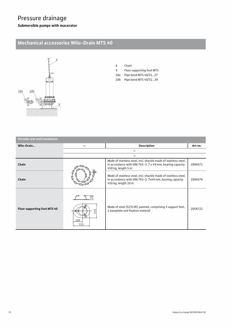
70 Subject to change 09/2009 WILO SE
Pressure drainageSubmersible pumps with macerator
Mechanical accessories Wilo-Drain MTS 40
Pressure drainage Submersible pumps with macerator Mechanical accessories Wilo-Drain MTS 40 Subject to change 09/2009 WILO SE Wilo catalogue C 3.1 - 50 Hz – Pumps stations and solids separation system
6
10b
9
10a
6 Chain9 Floor supporting foot MTS10a Pipe bend MTS 40/21...2710b Pipe bend MTS 40/31...39
Portable wet well installation
Wilo-Drain... – Description Art no.––
ChainMade of stainless steel, incl. shackle made of stainless steel, in accordance with DIN 763-3, 7 x 49 mm, bearing capacity 450 kg, length 5 m
2004671
ChainMade of stainless steel, incl. shackle made of stainless steel, in accordance with DIN 763-3, 7x49 mm, bearing capacity 450 kg, length 10 m
2004670
Floor supporting foot MTS 40 Made of steel (S235JR), painted, comprising 3 support feet, 1 baseplate and fixation material 2058721
270
78
315180

71
Pressure drainageSubmersible pumps with macerator
Pressure
drainage
Mechanical accessories Wilo-Drain MTS 40
Wilo catalogue C 3.1 - 50 Hz – Pumps stations and solids separation system
Pipe angle 90° MTS 40/21...27 Only for MTS 40/21...27, made of EN-GJMW-400-5, with fe-male/male thread G 1¼ / R 1¼ for DN 32 connection 2057400
Pipe angle 90° MTS 40/31...39
Only for MTS 40/31...39, made of EN-GJMW-400-5, with fe-male/male thread G 1½ / R 1½ incl. threaded flange (DN 40 / PN 16 in acc. with EN 1092), galvanised steel, with female thread R 1½ and 1 set of mounting accessories for DN 40 connection
2057401
Portable wet well installation
Wilo-Drain... – Description Art no.––
G 1¼
G 1
¼
76
76
G 1½
G 1½
G 1½
DN
40
85
85

72 Subject to change without prior notice 09/2009 WILO SE
Solids separation systemsPlanning guide
Wilo-EMUport solids separation systems
Solids separation systems Planning guide Wilo-EMUport solids separation systems Subject to change without prior notice 09/2009 WILO SE Wilo catalogue C 3.1 - 50 Hz – Pumps stations and solids separation systemRequirementThe amount of solids in domestic sewage is continuously increasing due to current water savings. This means that the pumps in pumping stations need even larger free ball passages, which also means an in-crease in pump power consumption.
FunctionWith the solids separation system, the inflowing sewage flows into the distribution tank and from there into the open solids separation tank. The solids are kept back here. Only prepurified sewage is now able to pass through the pump into the large, combined collection reservoir.
While the collection reservoir is filled, the water level in the solids separation tank rises. The shut-off ball automatically closes the inlet.
Now, pumping starts when the correct level has been reached. The pump pumps in the reverse direction. The sewage flows through the
solids separation reservoir and thus conveys the "filtered-out" solids into the outgoing pressure pipe.
Then, the entire solids separation system is flushed and cleaned. Pumping is stopped again, when the correct level has been reached. The shut-off ball drops, leaving the path free for a new filling se-quence. During this pumping sequence, the sewage is pumped into the other solids separation reservoir.
Advantages of the solids separation system• Uses pumps with free ball passage < 80 mm, thus reducing fuel re-
quirements and operating costs while increasing efficiency• Hygienic conditions for maintenance and assembly work• Pump room is clean, dry, and odourless• Less wear, since the solids are not pumped by the hydraulic unit• Submersible sewage pump with adjusted impeller and protection class IP 68 (submersible)
• No corrosion problems, no effect from the formation of hydrogen sulphide
1 = inlet pipe, 2 = manifold, 3 = solids collection reservoir, 4 = solids separation flap, 5 = collection reservoir with filtered sewage, 6 = shut-off ball, 7 = discharge pipeline, 8 = ventilation and exhaust
1
2
6
5
4
78
3

73
Solids separation systemsPlanning guide
Wilo catalogue C 3.1 - 50 Hz – Pumps stations and solids separation system
Agreements
Solids separation system
s
Solids separation systems Planning guide Agreements Subject to change without prior notice 09/2009 WILO SE Wilo catalogue C 3.1 - 50 Hz – Pumps stations and solids separation systemThe customer is responsible for the following upon completion of a sales agreement:
• Submission of signed and approved working drawing• Provision of paved vehicle access with unloading and manoeuvring space
• Completion of all earth and concrete work• Compacting of earth/soilCaution: To prevent sump deformation, the backfilled ground should be compacted uniformly in layers every 30 cm to D(PR) = 98 %.
• Acceptance and unloading of the product supplied as per the scope of delivery
• Concrete buoyancy safeguards should be arranged around the pump-ing station
• Storage and safekeeping of the material• Delivery, laying and connection of the ventilation and exhaust pipes, cable ducts and buried pipes to the pumping station.
• Provision of a class B/D coverWhen using a class B/D pump cover, the onsite creation of a concrete slab with a compressed layer is necessary. The concrete slab will transfer the forces to the compacted ground.
• Application for a supply connection to be sent to the local power supply network by a licensed electrician
• Laying the power connection as far as the switching system• Positioning of the switching cabinet pedestal
Assumption of riskThe assumption of risk is governed by the VOB (Vergabe- und Vert-ragsordnung für Bauleistungen - German Construction Contract Pro-cedures ). Meaning that the risk is transferred to the purchaser upon delivery of the pumping station. The purchaser should in particular ensure that the collection reservoirs are filled in good time, prevent the ingress of water and dirt in the dry room and to prevent the buoy-ancy of the pumping station.
End cleaningThe pumping station is supplied in a clean condition. If it is again nec-essary to clean the pumping station prior to acceptance, the operator must carry this out or this can be done at his cost.
TolerancesSubject to the tolerances of commercially available plastic.

74 Subject to change without prior notice 09/2009 WILO SE
Solids separation systemsPlanning guide
Enquiry data sheet for Wilo-EMUport FTS products
Solids separation systems Planning guide Enquiry data sheet for Wilo-EMUport FTS products Subject to change without prior notice 09/2009 WILO SE Wilo catalogue C 3.1 - 50 Hz – Pumps stations and solids separation system
Customer data Data for installation in a building or structure
Company: ___________________ Suction head (HA): ___________________m
Name: ___________________ Existing installation space: ___________________mm
Project name: ___________________ Sump base area: ___________________m
Deadline: ___________________
PE-HD pumping station data
General information Site altitude above MSL (HN) or � 0,00: ___________________m
Type of construction: o Newbuild Desired diameter: ___________________mm
o Reconstruction Installation depth to inlet floor (HB): ___________________m
Pumping station: o Wet well installation Ground water level above MSL (HG): ___________________m
o Dry well installation Traffic load in accordance with DIN EN 124:
o Solids separation system o Class A / o Class B / o Class C
Solids separation system: o in building or structure
o in PE-HD sump Equipment
Type of fluid: o Rainwater o Switchgear o Residual-current-operated pro-tection switch
o Sewage
o Frequency converter o Soft starter
o Display for o Pump(s) operation
Basic data o Operating hours
Inlet amount: ___________________l/s o Tank filling level
Flow rate per pump*: ___________________l/s o Pump(s) fault(s)
Delivery head per pump: ___________________m o Fault, flooding
Number of pumps: ___________________ o Data transmission o Cable
Number of pumps on standby: ___________________ o GSM / UMTS module
Inlet pipe: o Level control device o Pneumatic
Diameter (DN): ___________________ o Hydrostatic/capacitive
With gate valve: o Yes/ o No o Sump lighting o Fan
Pressure pipe o Volume flow rate meter o Compact
Inside diameter (Di): ___________________ o With external display
Drawing available: o Yes/ o No o Outdoor cabinet for switchgear
o Prepared for electricity meter
o Emergency power connection
* = in relation to the minimum flow velocity > 0.7 m/s (e.g. DIN 100: min. 4.95 l/s)
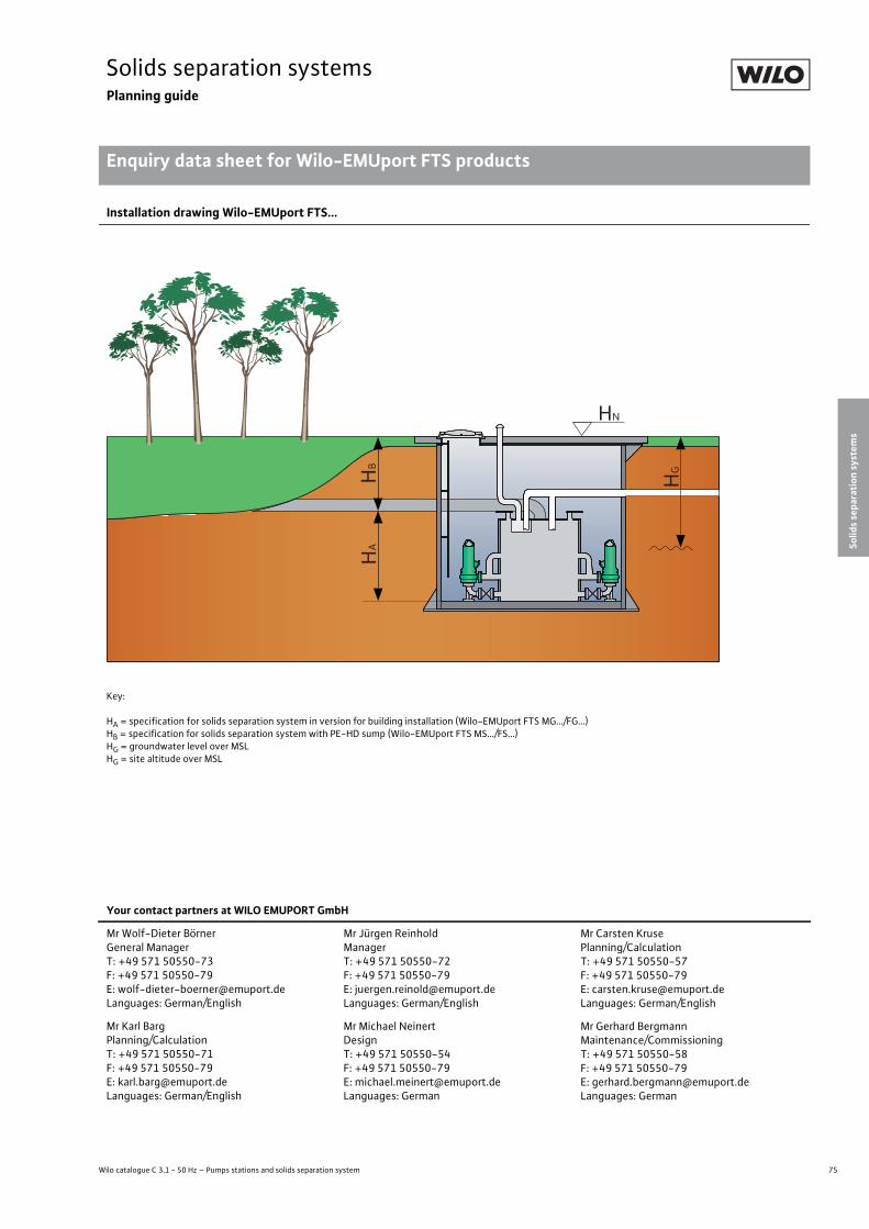
75
Solids separation systemsPlanning guide
Wilo catalogue C 3.1 - 50 Hz – Pumps stations and solids separation system
Enquiry data sheet for Wilo-EMUport FTS products
Solids separation system
s
Solids separation systems Planning guide Enquiry data sheet for Wilo-EMUport FTS products Subject to change without prior notice 09/2009 WILO SE Wilo catalogue C 3.1 - 50 Hz – Pumps stations and solids separation system
Installation drawing Wilo-EMUport FTS...
Key:
HA = specification for solids separation system in version for building installation (Wilo-EMUport FTS MG…/FG…)HB = specification for solids separation system with PE-HD sump (Wilo-EMUport FTS MS…/FS…)HG = groundwater level over MSLHG = site altitude over MSL
HA
HB
HG
HN
Your contact partners at WILO EMUPORT GmbH
Mr Wolf-Dieter BörnerGeneral ManagerT: +49 571 50550-73F: +49 571 50550-79E: [email protected]: German/English
Mr Jürgen ReinholdManagerT: +49 571 50550-72F: +49 571 50550-79E: [email protected]: German/English
Mr Carsten KrusePlanning/CalculationT: +49 571 50550-57F: +49 571 50550-79E: [email protected]: German/English
Mr Karl BargPlanning/CalculationT: +49 571 50550-71F: +49 571 50550-79E: [email protected]: German/English
Mr Michael NeinertDesignT: +49 571 50550-54F: +49 571 50550-79E: [email protected]: German
Mr Gerhard BergmannMaintenance/CommissioningT: +49 571 50550-58F: +49 571 50550-79E: [email protected]: German
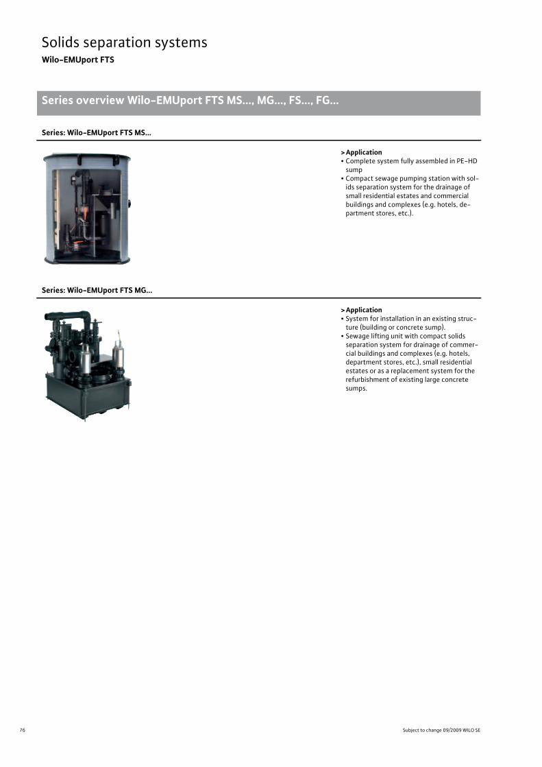
76 Subject to change 09/2009 WILO SE
Solids separation systemsWilo-EMUport FTS
Series overview Wilo-EMUport FTS MS..., MG..., FS..., FG...
Solids separation systems Wilo-EMUport FTS Series overview Wilo-EMUport FTS MS..., MG..., FS..., FG... Subject to change 09/2009 WILO SE Wilo catalogue C 3.1 - 50 Hz – Pumps stations and solids separation system
Series: Wilo-EMUport FTS MS...
>Application• Complete system fully assembled in PE-HD sump
• Compact sewage pumping station with sol-ids separation system for the drainage of small residential estates and commercial buildings and complexes (e.g. hotels, de-partment stores, etc.).
Series: Wilo-EMUport FTS MG...
>Application• System for installation in an existing struc-ture (building or concrete sump).
• Sewage lifting unit with compact solids separation system for drainage of commer-cial buildings and complexes (e.g. hotels, department stores, etc.), small residential estates or as a replacement system for the refurbishment of existing large concrete sumps.

77
Solids separation systemsWilo-EMUport FTS
Wilo catalogue C 3.1 - 50 Hz – Pumps stations and solids separation system
Series overview Wilo-EMUport FTS MS..., MG..., FS..., FG...
Solids separation system
s
Solids separation systems Wilo-EMUport FTS Series overview Wilo-EMUport FTS MS..., MG..., FS..., FG... Subject to change 09/2009 WILO SE Wilo catalogue C 3.1 - 50 Hz – Pumps stations and solids separation system
Series: Wilo-EMUport FTS MS...
>Special features/product advantages• Energy saving due to pumps with narrow ball passage, which produces better efficiency than with conventional sewage pumping stations
• Considerably less susceptible to plugging as the pumps do not come into contact with the sol-ids in the wastewater
• Uninterrupted operation during maintenance or repair work due to the station's double-pump design and individual shut-off of the solids separation reservoirs
• All parts are accessible from outside, so very easy to maintain and hygienic• Resistance to corrosion and long life due to construction from PE-HD material• Can be used in drinking water protection areas (protected water catchment zones), being uni-formly fuse-welded and absolutely watertight
• Defined interface, being a fully-assembled pumping station• Quick and cost-effective installation and commissioning on site, being delivered fully assem-bled in sump
• Acceptance inspection and testing can be done at the factory
>Additional information Page• Series description. . . . . . . . . . . . . . . . . 83
Series: Wilo-EMUport FTS MG...
>Special features/product advantages• Energy saving due to pumps with narrow ball passage, which produces better efficiency than with conventional sewage pumping stations
• Considerably less susceptible to plugging as the pumps do not come into contact with the sol-ids in the wastewater
• Uninterrupted operation during maintenance or repair work due to the station's double-pump design and individual shut-off of the solids separation reservoirs
• All parts are accessible from outside, so very easy to maintain and hygienic• Resistance to corrosion and long life due to construction from PE-HD material
>Additional information Page• Series description. . . . . . . . . . . . . . . . . 87

78 Subject to change 09/2009 WILO SE
Solids separation systemsWilo-EMUport FTS
Series overview Wilo-EMUport FTS MS..., MG..., FS..., FG...
Solids separation systems Wilo-EMUport FTS Series overview Wilo-EMUport FTS MS..., MG..., FS..., FG... Subject to change 09/2009 WILO SE Wilo catalogue C 3.1 - 50 Hz – Pumps stations and solids separation system
Series: Wilo-EMUport FTS FS...
>Application• Complete system fully assembled in PE-HD sump
• Sewage pumping station with solids separa-tion system for drainage of larger residential estates and boroughs.
Series: Wilo-EMUport FTS FG...
>Application• System for installation in an existing struc-ture (building or concrete sump).
• Sewage lifting unit with solids separation system for drainage of large residential es-tates and boroughs or as a replacement sys-tem for the refurbishment of existing large concrete sumps.

79
Solids separation systemsWilo-EMUport FTS
Wilo catalogue C 3.1 - 50 Hz – Pumps stations and solids separation system
Series overview Wilo-EMUport FTS MS..., MG..., FS..., FG...
Solids separation system
s
Solids separation systems Wilo-EMUport FTS Series overview Wilo-EMUport FTS MS..., MG..., FS..., FG... Subject to change 09/2009 WILO SE Wilo catalogue C 3.1 - 50 Hz – Pumps stations and solids separation system
Series: Wilo-EMUport FTS FS...
>Special features/product advantages• Energy saving due to pumps with narrow ball passage, which produces better efficiency than with conventional sewage pumping stations
• Considerably less susceptible to plugging as the pumps do not come into contact with the solids in the wastewater
• Uninterrupted operation during maintenance or repair work due to the station's double-pump design and individual shut-off of the solids separation reservoirs
• All parts are accessible from outside, so very easy to maintain and hygienic• Resistance to corrosion and long life due to construction from PE-HD material• Can be used in drinking water protection areas (protected water catchment zones), being uni-formly fuse-welded and absolutely watertight
• Defined interface, being a fully-assembled pumping station• Quick and cost-effective installation and commissioning on site, being delivered fully assem-bled in the sump
• Acceptance inspection and testing can be done at the factory
>Additional information Page• Series description. . . . . . . . . . . . . . . . . 91
Series: Wilo-EMUport FTS FG...
>Special features/product advantages• Energy saving due to pumps with narrow ball passage, which produces better efficiency than with conventional sewage pumping stations
• Considerably less susceptible to plugging as the pumps do not come into contact with the solids in the wastewater
• Uninterrupted operation during maintenance or repair work due to the station's double-pump design and individual shut-off of the solids separation reservoirs
• All parts are accessible from outside, so very easy to maintain and hygienic• Resistance to corrosion and long life due to construction from PE-HD material
>Additional information Page• Series description. . . . . . . . . . . . . . . . . 95
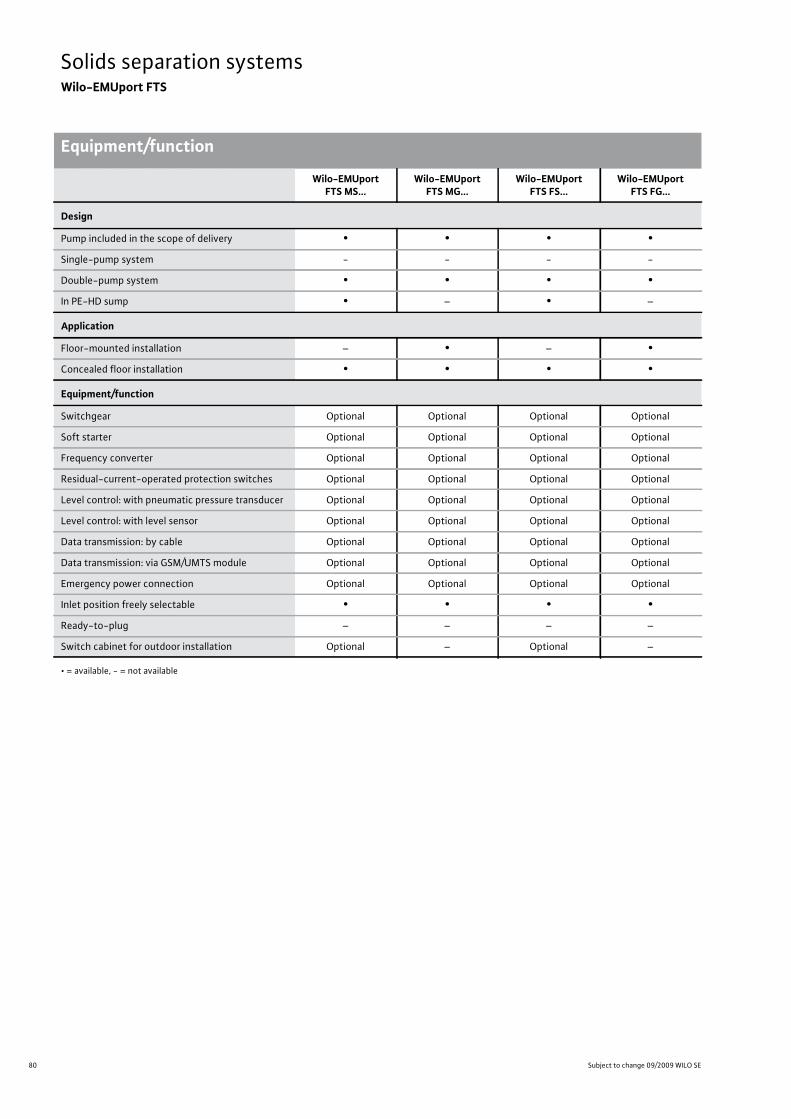
80 Subject to change 09/2009 WILO SE
Solids separation systemsWilo-EMUport FTS
Equipment/functionSolids separation systems Wilo-EMUport FTS Equipment/function Subject to change 09/2009 WILO SE Wilo catalogue C 3.1 - 50 Hz – Pumps stations and solids separation system
Wilo-EMUport FTS MS...
Wilo-EMUport FTS MG...
Wilo-EMUport FTS FS...
Wilo-EMUport FTS FG...
Design
Pump included in the scope of delivery • • • •Single-pump system - - - -
Double-pump system • • • •In PE-HD sump • – • –
Application
Floor-mounted installation – • – •Concealed floor installation • • • •
Equipment/function
Switchgear Optional Optional Optional Optional
Soft starter Optional Optional Optional Optional
Frequency converter Optional Optional Optional Optional
Residual-current-operated protection switches Optional Optional Optional Optional
Level control: with pneumatic pressure transducer Optional Optional Optional Optional
Level control: with level sensor Optional Optional Optional Optional
Data transmission: by cable Optional Optional Optional Optional
Data transmission: via GSM/UMTS module Optional Optional Optional Optional
Emergency power connection Optional Optional Optional Optional
Inlet position freely selectable • • • •Ready-to-plug – – – –
Switch cabinet for outdoor installation Optional – Optional –
• = available, - = not available

81
Solids separation systemsWilo-EMUport FTS
Wilo catalogue C 3.1 - 50 Hz – Pumps stations and solids separation system
Technical data
Solids separation system
s
Solids separation systems Wilo-EMUport FTS Technical data Subject to change 09/2009 WILO SE Wilo catalogue C 3.1 - 50 Hz – Pumps stations and solids separation system
Systems with PE-HD sump
Wilo-EMUport FTS... System output Volume of collec-tion reservoir
Installation depth below ground
surface level up to inlet floor
Max. delivery head
Minimum installa-tion opening
Sump diameter
Q V Hb H – Di[m³/h] [l] [mm] [m] [mm]
MS 590-1500 6 260 590 25 - 1500
MS 740-1500 10 320 740 25 - 1500
MS 940-1500 15 580 940 25 - 1500
MS 590-2000 10 460 590 25 - 2000
MS 740-2000 15 570 740 25 - 2000
MS 940-2000 15 1040 940 25 - 2000
MS 1200-2000 25 1070 1200 50 - 2000
MS 1500-2000 35 1070 1500 50 - 2000
FS 2000 65...90 2090 1460...1660 70 - 2000
FS 2500 130...190 2970 1660...2160 70 - 2500
FS 3000 230...310 4500 2160...2560 80 - 3000
FS 3500 310...410 5350 2160...2560 80 - 3500
Larger inlets and intermediate sizes available on request.
Systems without sump for the installation inside buildings
Wilo-EMUport FTS... System output Volume of collec-tion reservoir
Installation depth below inlet floor
Max. delivery head
Minimum installa-tion opening
Min. concrete sump diameter
Q V Ha H – Di min.[m³/h] [l] [mm] [m] [mm]
MG 400-1500 1 40 400 25 1000 x 1150 1500
MG 550-1500 6 140 550 25 1000 x 1150 1500
MG 750-1500 10 320 750 25 1000 x 1150 1500
MG 750-2500 15 640 750 25 1800 x 1800 2500
MG 1200-2500 25 950 1200 50 1800 x 1800 2500
MG 1500-2500 30 950 1500 50 1800 x 1800 2500
FG 1500 75...100 2170 1200...1400 80 1800 x 2500 –
FG 2000 130...200 3860 1400...1900 85 2300 x 3000 –
FG 2500 260...380 7020 1900...2300 80 2800 x 3500 –
FG 3000 450 13640 2300 75 3300 x 4000 –
FG 3500 600 18570 2300 65 3800 x 4500 –
Larger inlets and intermediate sizes available on request.
82 Subject to change 09/2009 WILO SE
Solids separation systemsWilo-EMUport FTS
Technical data
Solids separation systems Wilo-EMUport FTS Technical data Subject to change 09/2009 WILO SE Wilo catalogue C 3.1 - 50 Hz – Pumps stations and solids separation system

83
Solids separation systemsWilo-EMUport FTS
Wilo catalogue C 3.1 - 50 Hz – Pumps stations and solids separation system
Series description Wilo-EMUport FTS MS...
Solids separation system
s
Solids separation systems Wilo-EMUport FTS Series description Wilo-EMUport FTS MS... Subject to change 09/2009 WILO SE Wilo catalogue C 3.1 - 50 Hz – Pumps stations and solids separation system
DesignCompact sewage pumping station with solids separation system in PE-HD sump
Type key
Application• Complete system fully assembled in PE-HD sump• Compact sewage pumping station with solids separation system for the drainage of small residential estates and commercial buildings and complexes (e.g. hotels, department stores, etc.).
Special features/product advantages• Energy saving due to pumps with narrow ball passage, which produc-es better efficiency than with conventional sewage pumping stations
• Considerably less susceptible to plugging as the pumps do not come into contact with the solids in the wastewater
• Uninterrupted operation during maintenance or repair work due to the station's double-pump design and individual shut-off of the sol-ids separation reservoirs
• All parts are accessible from outside, so very easy to maintain and hy-gienic
• Resistance to corrosion and long life due to construction from PE-HD material
• Can be used in drinking water protection areas (protected water catchment zones), being uniformly fuse-welded and absolutely wa-tertight
• Defined interface, being a fully-assembled pumping station• Quick and cost-effective installation and commissioning on site, be-ing delivered fully assembled in sump
• Acceptance inspection and testing can be done at the factory
Technical data• Max. inlet: 35 m3/h• Max. useable tank volume: 800 l• Max. delivery head: 60 m• Max. installation depth below inlet floor: 1500 mm• Mains connection: 3~400 V, 50 Hz
Equipment/function• Solids separation system with solids separation reservoir and collec-tion reservoir
• Two dry-well installed submersible sewage pumps for alternating mode
• Switching system and level measurement according to customer re-quest
• Individual shut-off of the solids collection reservoirs
Materials• Solids separation system: PE-HD• Pipework: PE-HD• Pumps and non-return ball valves: grey cast iron, coated
Description/designConnection-ready fully submersible sewage pumping station with solids separation system and a gas- and watertight collection tank. Equipped as a double-pump system with submersible sewage pumps, running in alternating mode. Easy handling and optimum tank drain-age by means of depth suction.
Due to the use of solids separation tanks, the pumps do not come in-to contact with the solids in the fluid. In this way, pumps with narrow ball passages and optimised efficiency can be used for pumping sew-age.
The dry well installation of the pumps and their configuration as a re-dundant double-pump system ensures maximum hygiene, ease of maintenance, and operational reliability. The complete system, apart from the pumps and non-return valve, is made of corrosion-resistant PE-HD.
Attention: The accompanying switchgear is not submersible and must for that reason be arranged in such a way that it is secure against flooding.
Options• Other reservoir sizes and suction heads can be produced as requested by the customer, e.g. due to existing installation openings or door di-mensions.
• Inductive flow rate gauge• Slide valve for inlet• Slide valve for discharge pipeline• Flange outlet for discharge pipeline• Flush connection
Scope of delivery• Ready-to-install solids separation system• Two sewage pumps with 10 m cable• Individual shut-off of the solids separation reservoirs• Switchgear with level measurement• Discharge pipe junction with smooth pipe end• Non-return valve
DimensioningThe installation must be configured for the maximum wastewater flow occurring, including a possible additional peak flow. The pumps must be configured for a minimum flow velocity of 0.7 m/s in the dis-charge pipeline (e.g. min. 21.6 m³/h with DN 100 pipe).
The manometric delivery head is calculated as the maximum static head + pipeline friction losses + pumping station losses of 1.0 mWS.
Example: Wilo-EMUport FTS MS 740-1500
FTS Solids separation system
M Version (M = compact version, F = large version)
S Type of installation (G = in building, S = with PE-HD sump)
740 Installation depth below inlet floor in mm
1500 Sump diameter in mm
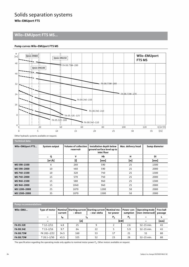
84 Subject to change 09/2009 WILO SE
Solids separation systemsWilo-EMUport FTS
Wilo-EMUport FTS MS...
Solids separation systems Wilo-EMUport FTS Wilo-EMUport FTS MS... Subject to change 09/2009 WILO SE Wilo catalogue C 3.1 - 50 Hz – Pumps stations and solids separation system
Pump curves Wilo-EMUport FTS MS
Other hydraulic systems available on request.
0
8
24
32
40
48
20 40 60 80 100 120 Q [m³/h]
16
0
H[m] Qmin DN80
Qmin DN100
Qmin DN150Wilo-EMUportFTS MS
0 5 10 15 20 25 30 35 [l/s]
FA 05.32E-100
FA 05.32E-125
FA 08.34E-110
FA 08.34E-140
FA 08.34E-150
FA 08.73W-200
FA 08.73W-180
FA 08.73W-170
Technical data
Wilo-EMUport FTS... System output Volume of collection reservoir
Installation depth below ground surface level up to
inlet floor
Max. delivery head Sump diameter
Q V Hb H Di[m³/h] [l] [mm] [m] [mm]
MS 590-1500 6 260 590 25 1500
MS 590-2000 10 460 590 25 2000
MS 740-1500 10 320 740 25 1500
MS 740-2000 15 570 740 25 2000
MS 940-1500 15 580 940 25 1500
MS 940-2000 15 1040 940 25 2000
MS 1200-2000 25 1070 1200 50 2000
MS 1500-2000 35 1070 1500 50 2000
Pump recommendations
Wilo-EMU... Type of motor Nominal current
Starting current - direct
Starting current - star-delta
Nominal mo-tor power
Power con-sumption
Operating mode (non-immersed)
Free ball passage
– IN IA P2 P1 – L– [A] [kW] – [mm]
FA 05.32E T 12-2/11 4.8 25 9 2 2.6 S2-15 min. 45
FA 08.34E T 13-2/16 9.7 64 22 5 5.9 S2-15 min. 45
FA 08.73W FK 202-2/22 34.5 160 53 17 21 S1 80
FA 08.73W T 20.1-2/30 45.5 325 52 23 28 S2-15 min. 80
The specification regarding the operating mode only applies to nominal motor power P2. Other motors available on request.
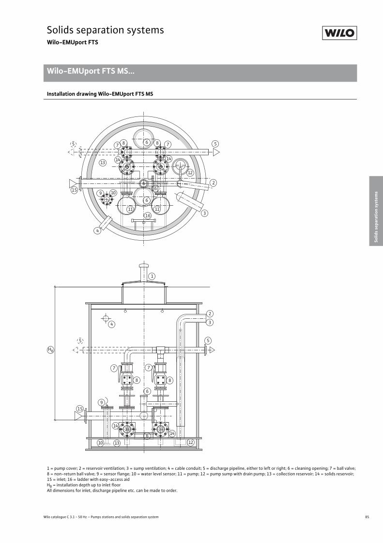
85
Solids separation systemsWilo-EMUport FTS
Wilo catalogue C 3.1 - 50 Hz – Pumps stations and solids separation system
Wilo-EMUport FTS MS...
Solids separation system
s
Solids separation systems Wilo-EMUport FTS Wilo-EMUport FTS MS... Subject to change 09/2009 WILO SE Wilo catalogue C 3.1 - 50 Hz – Pumps stations and solids separation system
Installation drawing Wilo-EMUport FTS MS
1 = pump cover; 2 = reservoir ventilation; 3 = sump ventilation; 4 = cable conduit; 5 = discharge pipeline, either to left or right; 6 = cleaning opening; 7 = ball valve; 8 = non-return ball valve; 9 = sensor flange; 10 = water level sensor; 11 = pump; 12 = pump sump with drain pump; 13 = collection reservoir; 14 = solids reservoir; 15 = inlet; 16 = ladder with easy-access aidHB = installation depth up to inlet floorAll dimensions for inlet, discharge pipeline etc. can be made to order.
2
3
4
55
6
67 78 8
9 10
1111
12
131414
15
16
66
1
2
34
55
6
6
7 7
88
9
10
1111
1213
14
14
15
HB

86 Subject to change 09/2009 WILO SE
Solids separation systemsWilo-EMUport FTS
Wilo-EMUport FTS MS...
Solids separation systems Wilo-EMUport FTS Wilo-EMUport FTS MS... Subject to change 09/2009 WILO SE Wilo catalogue C 3.1 - 50 Hz – Pumps stations and solids separation system
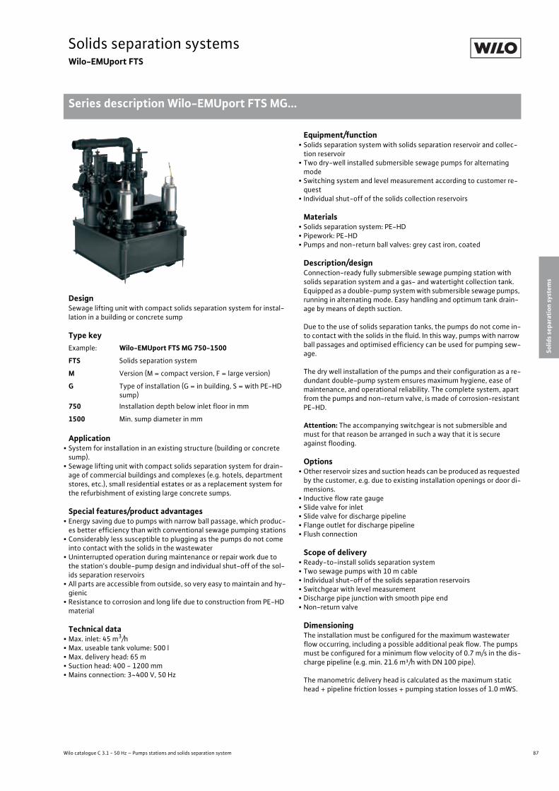
87
Solids separation systemsWilo-EMUport FTS
Wilo catalogue C 3.1 - 50 Hz – Pumps stations and solids separation system
Series description Wilo-EMUport FTS MG...
Solids separation system
s
Solids separation systems Wilo-EMUport FTS Series description Wilo-EMUport FTS MG... Subject to change 09/2009 WILO SE Wilo catalogue C 3.1 - 50 Hz – Pumps stations and solids separation system
DesignSewage lifting unit with compact solids separation system for instal-lation in a building or concrete sump
Type key
Application• System for installation in an existing structure (building or concrete sump).
• Sewage lifting unit with compact solids separation system for drain-age of commercial buildings and complexes (e.g. hotels, department stores, etc.), small residential estates or as a replacement system for the refurbishment of existing large concrete sumps.
Special features/product advantages• Energy saving due to pumps with narrow ball passage, which produc-es better efficiency than with conventional sewage pumping stations
• Considerably less susceptible to plugging as the pumps do not come into contact with the solids in the wastewater
• Uninterrupted operation during maintenance or repair work due to the station's double-pump design and individual shut-off of the sol-ids separation reservoirs
• All parts are accessible from outside, so very easy to maintain and hy-gienic
• Resistance to corrosion and long life due to construction from PE-HD material
Technical data• Max. inlet: 45 m3/h• Max. useable tank volume: 500 l• Max. delivery head: 65 m• Suction head: 400 - 1200 mm• Mains connection: 3~400 V, 50 Hz
Equipment/function• Solids separation system with solids separation reservoir and collec-tion reservoir
• Two dry-well installed submersible sewage pumps for alternating mode
• Switching system and level measurement according to customer re-quest
• Individual shut-off of the solids collection reservoirs
Materials• Solids separation system: PE-HD• Pipework: PE-HD• Pumps and non-return ball valves: grey cast iron, coated
Description/designConnection-ready fully submersible sewage pumping station with solids separation system and a gas- and watertight collection tank. Equipped as a double-pump system with submersible sewage pumps, running in alternating mode. Easy handling and optimum tank drain-age by means of depth suction.
Due to the use of solids separation tanks, the pumps do not come in-to contact with the solids in the fluid. In this way, pumps with narrow ball passages and optimised efficiency can be used for pumping sew-age.
The dry well installation of the pumps and their configuration as a re-dundant double-pump system ensures maximum hygiene, ease of maintenance, and operational reliability. The complete system, apart from the pumps and non-return valve, is made of corrosion-resistant PE-HD.
Attention: The accompanying switchgear is not submersible and must for that reason be arranged in such a way that it is secure against flooding.
Options• Other reservoir sizes and suction heads can be produced as requested by the customer, e.g. due to existing installation openings or door di-mensions.
• Inductive flow rate gauge• Slide valve for inlet• Slide valve for discharge pipeline• Flange outlet for discharge pipeline• Flush connection
Scope of delivery• Ready-to-install solids separation system• Two sewage pumps with 10 m cable• Individual shut-off of the solids separation reservoirs• Switchgear with level measurement• Discharge pipe junction with smooth pipe end• Non-return valve
DimensioningThe installation must be configured for the maximum wastewater flow occurring, including a possible additional peak flow. The pumps must be configured for a minimum flow velocity of 0.7 m/s in the dis-charge pipeline (e.g. min. 21.6 m³/h with DN 100 pipe).
The manometric delivery head is calculated as the maximum static head + pipeline friction losses + pumping station losses of 1.0 mWS.
Example: Wilo-EMUport FTS MG 750-1500
FTS Solids separation system
M Version (M = compact version, F = large version)
G Type of installation (G = in building, S = with PE-HD sump)
750 Installation depth below inlet floor in mm
1500 Min. sump diameter in mm
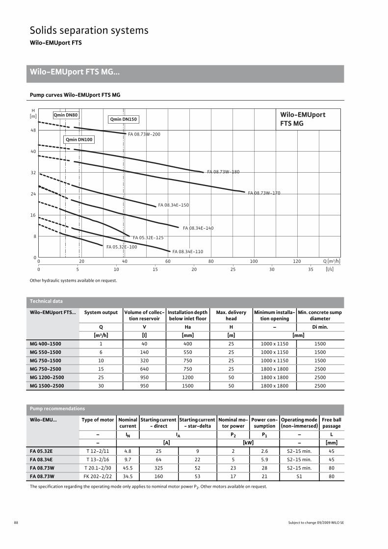
88 Subject to change 09/2009 WILO SE
Solids separation systemsWilo-EMUport FTS
Wilo-EMUport FTS MG...
Solids separation systems Wilo-EMUport FTS Wilo-EMUport FTS MG... Subject to change 09/2009 WILO SE Wilo catalogue C 3.1 - 50 Hz – Pumps stations and solids separation system
Pump curves Wilo-EMUport FTS MG
Other hydraulic systems available on request.
0
8
24
32
40
48
20 40 60 80 100 120 Q [m³/h]
16
0
H[m] Qmin DN80
Qmin DN100
Qmin DN150Wilo-EMUportFTS MG
0 5 10 15 20 25 30 35 [l/s]
FA 05.32E-100
FA 05.32E-125
FA 08.34E-110
FA 08.34E-140
FA 08.34E-150
FA 08.73W-200
FA 08.73W-180
FA 08.73W-170
Technical data
Wilo-EMUport FTS... System output Volume of collec-tion reservoir
Installation depth below inlet floor
Max. delivery head
Minimum installa-tion opening
Min. concrete sump diameter
Q V Ha H – Di min.[m³/h] [l] [mm] [m] [mm]
MG 400-1500 1 40 400 25 1000 x 1150 1500
MG 550-1500 6 140 550 25 1000 x 1150 1500
MG 750-1500 10 320 750 25 1000 x 1150 1500
MG 750-2500 15 640 750 25 1800 x 1800 2500
MG 1200-2500 25 950 1200 50 1800 x 1800 2500
MG 1500-2500 30 950 1500 50 1800 x 1800 2500
Pump recommendations
Wilo-EMU... Type of motor Nominal current
Starting current - direct
Starting current - star-delta
Nominal mo-tor power
Power con-sumption
Operating mode (non-immersed)
Free ball passage
– IN IA P2 P1 – L– [A] [kW] – [mm]
FA 05.32E T 12-2/11 4.8 25 9 2 2.6 S2-15 min. 45
FA 08.34E T 13-2/16 9.7 64 22 5 5.9 S2-15 min. 45
FA 08.73W T 20.1-2/30 45.5 325 52 23 28 S2-15 min. 80
FA 08.73W FK 202-2/22 34.5 160 53 17 21 S1 80
The specification regarding the operating mode only applies to nominal motor power P2. Other motors available on request.

89
Solids separation systemsWilo-EMUport FTS
Wilo catalogue C 3.1 - 50 Hz – Pumps stations and solids separation system
Wilo-EMUport FTS MG...
Solids separation system
s
Solids separation systems Wilo-EMUport FTS Wilo-EMUport FTS MG... Subject to change 09/2009 WILO SE Wilo catalogue C 3.1 - 50 Hz – Pumps stations and solids separation system
Installation drawing Wilo-EMUport FTS MG
1 = inlet; 2 = discharge pipeline; 3 = non-return ball valve; 4 = ball valve; 5 = sensor flange; 6 = water level sensor; 7 = solids reservoir; 8 = pump; 9 = cleaning opening;10 = collection reservoir; 11 = reservoir ventilation; 12 = check valveHA = suction head; inlet floor to ground levelAll dimensions for inlet, discharge pipeline etc. can be made to order.
1
2
2
3
3
4
4
5
6
7
7
8
8
9
10
1
2
4
3
7
10
1
9
22
9
9
5
6
7 7
8 8
10
11
11
12
12
12 12
HA HA

90 Subject to change 09/2009 WILO SE
Solids separation systemsWilo-EMUport FTS
Wilo-EMUport FTS MG...
Solids separation systems Wilo-EMUport FTS Wilo-EMUport FTS MG... Subject to change 09/2009 WILO SE Wilo catalogue C 3.1 - 50 Hz – Pumps stations and solids separation system
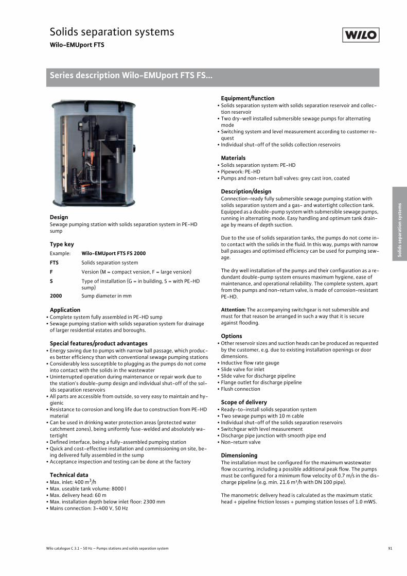
91
Solids separation systemsWilo-EMUport FTS
Wilo catalogue C 3.1 - 50 Hz – Pumps stations and solids separation system
Series description Wilo-EMUport FTS FS...
Solids separation system
s
Solids separation systems Wilo-EMUport FTS Series description Wilo-EMUport FTS FS... Subject to change 09/2009 WILO SE Wilo catalogue C 3.1 - 50 Hz – Pumps stations and solids separation system
DesignSewage pumping station with solids separation system in PE-HD sump
Type key
Application• Complete system fully assembled in PE-HD sump• Sewage pumping station with solids separation system for drainage of larger residential estates and boroughs.
Special features/product advantages• Energy saving due to pumps with narrow ball passage, which produc-es better efficiency than with conventional sewage pumping stations
• Considerably less susceptible to plugging as the pumps do not come into contact with the solids in the wastewater
• Uninterrupted operation during maintenance or repair work due to the station's double-pump design and individual shut-off of the sol-ids separation reservoirs
• All parts are accessible from outside, so very easy to maintain and hy-gienic
• Resistance to corrosion and long life due to construction from PE-HD material
• Can be used in drinking water protection areas (protected water catchment zones), being uniformly fuse-welded and absolutely wa-tertight
• Defined interface, being a fully-assembled pumping station• Quick and cost-effective installation and commissioning on site, be-ing delivered fully assembled in the sump
• Acceptance inspection and testing can be done at the factory
Technical data• Max. inlet: 400 m3/h• Max. useable tank volume: 8000 l• Max. delivery head: 60 m• Max. installation depth below inlet floor: 2300 mm• Mains connection: 3~400 V, 50 Hz
Equipment/function• Solids separation system with solids separation reservoir and collec-tion reservoir
• Two dry-well installed submersible sewage pumps for alternating mode
• Switching system and level measurement according to customer re-quest
• Individual shut-off of the solids collection reservoirs
Materials• Solids separation system: PE-HD• Pipework: PE-HD• Pumps and non-return ball valves: grey cast iron, coated
Description/designConnection-ready fully submersible sewage pumping station with solids separation system and a gas- and watertight collection tank. Equipped as a double-pump system with submersible sewage pumps, running in alternating mode. Easy handling and optimum tank drain-age by means of depth suction.
Due to the use of solids separation tanks, the pumps do not come in-to contact with the solids in the fluid. In this way, pumps with narrow ball passages and optimised efficiency can be used for pumping sew-age.
The dry well installation of the pumps and their configuration as a re-dundant double-pump system ensures maximum hygiene, ease of maintenance, and operational reliability. The complete system, apart from the pumps and non-return valve, is made of corrosion-resistant PE-HD.
Attention: The accompanying switchgear is not submersible and must for that reason be arranged in such a way that it is secure against flooding.
Options• Other reservoir sizes and suction heads can be produced as requested by the customer, e.g. due to existing installation openings or door dimensions.
• Inductive flow rate gauge• Slide valve for inlet• Slide valve for discharge pipeline• Flange outlet for discharge pipeline• Flush connection
Scope of delivery• Ready-to-install solids separation system• Two sewage pumps with 10 m cable• Individual shut-off of the solids separation reservoirs• Switchgear with level measurement• Discharge pipe junction with smooth pipe end• Non-return valve
DimensioningThe installation must be configured for the maximum wastewater flow occurring, including a possible additional peak flow. The pumps must be configured for a minimum flow velocity of 0.7 m/s in the dis-charge pipeline (e.g. min. 21.6 m³/h with DN 100 pipe).
The manometric delivery head is calculated as the maximum static head + pipeline friction losses + pumping station losses of 1.0 mWS.
Example: Wilo-EMUport FTS FS 2000
FTS Solids separation system
F Version (M = compact version, F = large version)
S Type of installation (G = in building, S = with PE-HD sump)
2000 Sump diameter in mm
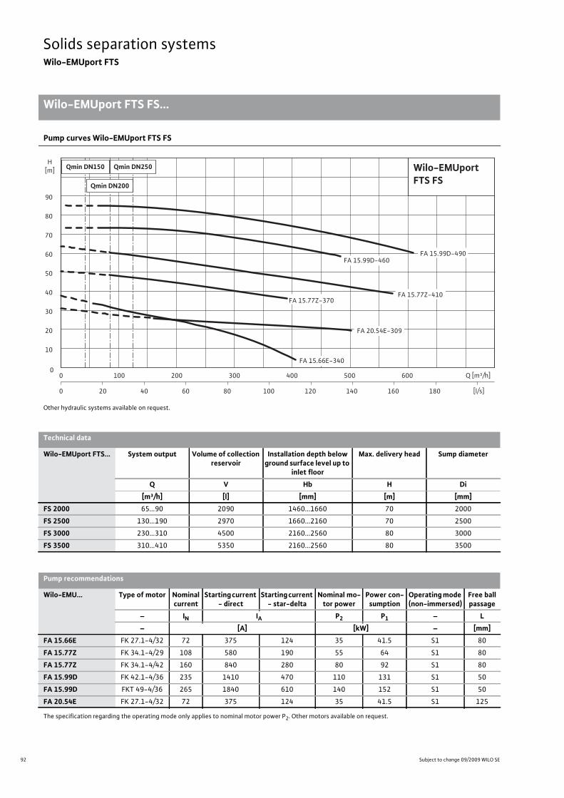
92 Subject to change 09/2009 WILO SE
Solids separation systemsWilo-EMUport FTS
Wilo-EMUport FTS FS...
Solids separation systems Wilo-EMUport FTS Wilo-EMUport FTS FS... Subject to change 09/2009 WILO SE Wilo catalogue C 3.1 - 50 Hz – Pumps stations and solids separation system
Pump curves Wilo-EMUport FTS FS
Other hydraulic systems available on request.
100 120 140 160 180
100 200 300 400 500 600
20 40 60 800
00
10
20
30
40
50
60
70
80
90
H[m]
[l/s]
Q [m³/h]
Qmin DN200
Qmin DN250Qmin DN150 Wilo-EMUportFTS FS
FA 20.54E-309
FA 15.99D-460FA 15.99D-490
FA 15.77Z-370FA 15.77Z-410
FA 15.66E-340
Technical data
Wilo-EMUport FTS... System output Volume of collection reservoir
Installation depth below ground surface level up to
inlet floor
Max. delivery head Sump diameter
Q V Hb H Di[m³/h] [l] [mm] [m] [mm]
FS 2000 65...90 2090 1460...1660 70 2000
FS 2500 130...190 2970 1660...2160 70 2500
FS 3000 230...310 4500 2160...2560 80 3000
FS 3500 310...410 5350 2160...2560 80 3500
Pump recommendations
Wilo-EMU... Type of motor Nominal current
Starting current - direct
Starting current - star-delta
Nominal mo-tor power
Power con-sumption
Operating mode (non-immersed)
Free ball passage
– IN IA P2 P1 – L– [A] [kW] – [mm]
FA 15.66E FK 27.1-4/32 72 375 124 35 41.5 S1 80
FA 15.77Z FK 34.1-4/29 108 580 190 55 64 S1 80
FA 15.77Z FK 34.1-4/42 160 840 280 80 92 S1 80
FA 15.99D FK 42.1-4/36 235 1410 470 110 131 S1 50
FA 15.99D FKT 49-4/36 265 1840 610 140 152 S1 50
FA 20.54E FK 27.1-4/32 72 375 124 35 41.5 S1 125
The specification regarding the operating mode only applies to nominal motor power P2. Other motors available on request.
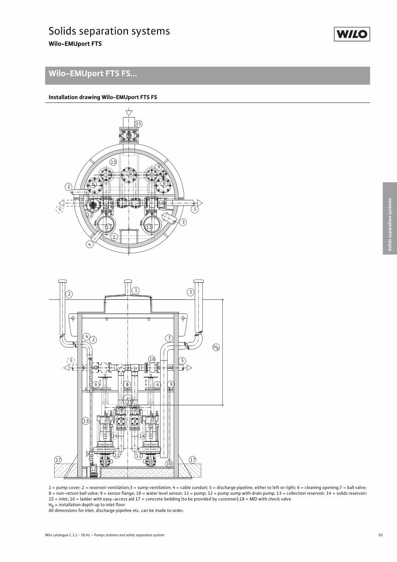
93
Solids separation systemsWilo-EMUport FTS
Wilo catalogue C 3.1 - 50 Hz – Pumps stations and solids separation system
Wilo-EMUport FTS FS...
Solids separation system
s
Solids separation systems Wilo-EMUport FTS Wilo-EMUport FTS FS... Subject to change 09/2009 WILO SE Wilo catalogue C 3.1 - 50 Hz – Pumps stations and solids separation system
Installation drawing Wilo-EMUport FTS FS
1 = pump cover; 2 = reservoir ventilation;3 = sump ventilation; 4 = cable conduit; 5 = discharge pipeline, either to left or right; 6 = cleaning opening;7 = ball valve; 8 = non-return ball valve; 9 = sensor flange; 10 = water level sensor; 11 = pump; 12 = pump sump with drain pump; 13 = collection reservoir; 14 = solids reservoir; 15 = inlet; 16 = ladder with easy-access aid 17 = concrete bedding (to be provided by customer);18 = MID with check valveHB = installation depth up to inlet floorAll dimensions for inlet, discharge pipeline etc. can be made to order.
12 3
4 32
55
6
7 7
88
9
10
1111
12
13
14 14
15
6 6
17 17
18
1
3
4
512
13
15
6
185
266
9
1111
HB

94 Subject to change 09/2009 WILO SE
Solids separation systemsWilo-EMUport FTS
Wilo-EMUport FTS FS...
Solids separation systems Wilo-EMUport FTS Wilo-EMUport FTS FS... Subject to change 09/2009 WILO SE Wilo catalogue C 3.1 - 50 Hz – Pumps stations and solids separation system
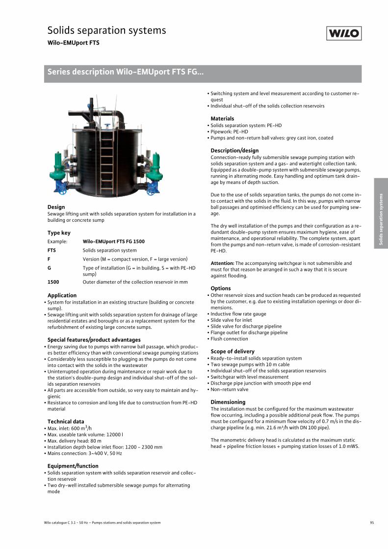
95
Solids separation systemsWilo-EMUport FTS
Wilo catalogue C 3.1 - 50 Hz – Pumps stations and solids separation system
Series description Wilo-EMUport FTS FG...
Solids separation system
s
Solids separation systems Wilo-EMUport FTS Series description Wilo-EMUport FTS FG... Subject to change 09/2009 WILO SE Wilo catalogue C 3.1 - 50 Hz – Pumps stations and solids separation system
DesignSewage lifting unit with solids separation system for installation in a building or concrete sump
Type key
Application• System for installation in an existing structure (building or concrete sump).
• Sewage lifting unit with solids separation system for drainage of large residential estates and boroughs or as a replacement system for the refurbishment of existing large concrete sumps.
Special features/product advantages• Energy saving due to pumps with narrow ball passage, which produc-es better efficiency than with conventional sewage pumping stations
• Considerably less susceptible to plugging as the pumps do not come into contact with the solids in the wastewater
• Uninterrupted operation during maintenance or repair work due to the station's double-pump design and individual shut-off of the sol-ids separation reservoirs
• All parts are accessible from outside, so very easy to maintain and hy-gienic
• Resistance to corrosion and long life due to construction from PE-HD material
Technical data• Max. inlet: 600 m3/h• Max. useable tank volume: 12000 l• Max. delivery head: 80 m• Installation depth below inlet floor: 1200 - 2300 mm• Mains connection: 3~400 V, 50 Hz
Equipment/function• Solids separation system with solids separation reservoir and collec-tion reservoir
• Two dry-well installed submersible sewage pumps for alternating mode
• Switching system and level measurement according to customer re-quest
• Individual shut-off of the solids collection reservoirs
Materials• Solids separation system: PE-HD• Pipework: PE-HD• Pumps and non-return ball valves: grey cast iron, coated
Description/designConnection-ready fully submersible sewage pumping station with solids separation system and a gas- and watertight collection tank. Equipped as a double-pump system with submersible sewage pumps, running in alternating mode. Easy handling and optimum tank drain-age by means of depth suction.
Due to the use of solids separation tanks, the pumps do not come in-to contact with the solids in the fluid. In this way, pumps with narrow ball passages and optimised efficiency can be used for pumping sew-age.
The dry well installation of the pumps and their configuration as a re-dundant double-pump system ensures maximum hygiene, ease of maintenance, and operational reliability. The complete system, apart from the pumps and non-return valve, is made of corrosion-resistant PE-HD.
Attention: The accompanying switchgear is not submersible and must for that reason be arranged in such a way that it is secure against flooding.
Options• Other reservoir sizes and suction heads can be produced as requested by the customer, e.g. due to existing installation openings or door di-mensions.
• Inductive flow rate gauge• Slide valve for inlet• Slide valve for discharge pipeline• Flange outlet for discharge pipeline• Flush connection
Scope of delivery• Ready-to-install solids separation system• Two sewage pumps with 10 m cable• Individual shut-off of the solids separation reservoirs• Switchgear with level measurement• Discharge pipe junction with smooth pipe end• Non-return valve
DimensioningThe installation must be configured for the maximum wastewater flow occurring, including a possible additional peak flow. The pumps must be configured for a minimum flow velocity of 0.7 m/s in the dis-charge pipeline (e.g. min. 21.6 m³/h with DN 100 pipe).
The manometric delivery head is calculated as the maximum static head + pipeline friction losses + pumping station losses of 1.0 mWS.
Example: Wilo-EMUport FTS FG 1500
FTS Solids separation system
F Version (M = compact version, F = large version)
G Type of installation (G = in building, S = with PE-HD sump)
1500 Outer diameter of the collection reservoir in mm

96 Subject to change 09/2009 WILO SE
Solids separation systemsWilo-EMUport FTS
Wilo-EMUport FTS FG...
Solids separation systems Wilo-EMUport FTS Wilo-EMUport FTS FG... Subject to change 09/2009 WILO SE Wilo catalogue C 3.1 - 50 Hz – Pumps stations and solids separation system
Pump curves Wilo-EMUport FTS FG
Other hydraulic systems available on request.
100 120 140 160 180
100 200 300 400 500 600
20 40 60 800
00
10
20
30
40
50
60
70
80
90
H[m]
[l/s]
Q [m³/h]
Qmin DN200
Qmin DN250Qmin DN150 Wilo-EMUportFTS FG
FA 20.54E-309
FA 15.99D-460FA 15.99D-490
FA 15.77Z-370FA 15.77Z-410
FA 15.66E-340
Technical data
Wilo-EMUport FTS... System output Volume of collection reservoir
Installation depth below inlet floor
Max. delivery head Minimum installa-tion opening
Q V Ha H –[m³/h] [l] [mm] [m] [mm]
FG 1500 75...100 2170 1200...1400 80 1800 x 2500
FG 2000 130...200 3860 1400...1900 85 2300 x 3000
FG 2500 260...380 7020 1900...2300 80 2800 x 3500
FG 3000 450 13640 2300 75 3300 x 4000
FG 3500 600 18570 2300 65 3800 x 4500
Pump recommendations
Wilo-EMU... Type of motor Nominal current
Starting current - direct
Starting current - star-delta
Nominal mo-tor power
Power con-sumption
Operating mode (non-immersed)
Free ball passage
– IN IA P2 P1 – L– [A] [kW] – [mm]
FA 15.66E FK 27.1-4/32 72 375 124 35 41.5 S1 80
FA 15.77Z FK 34.1-4/29 108 580 190 55 64 S1 80
FA 15.77Z FK 34.1-4/42 160 840 280 80 92 S1 80
FA 15.99D FK 42.1-4/36 235 1410 470 110 131 S1 50
FA 15.99D FKT 49-4/36 265 1840 610 140 152 S1 50
FA 20.54E FK 27.1-4/32 72 375 124 35 41.5 S1 125
The specification regarding the operating mode only applies to nominal motor power P2. Other motors available on request.
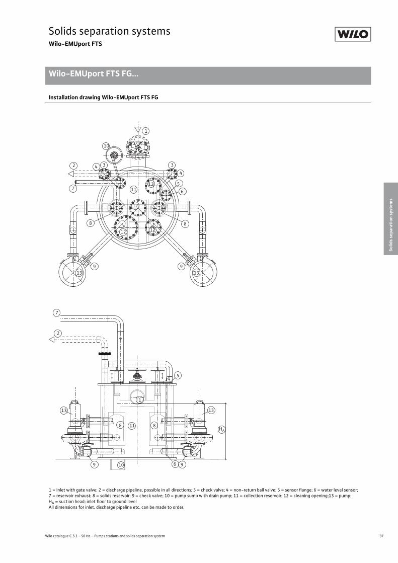
97
Solids separation systemsWilo-EMUport FTS
Wilo catalogue C 3.1 - 50 Hz – Pumps stations and solids separation system
Wilo-EMUport FTS FG...
Solids separation system
s
Solids separation systems Wilo-EMUport FTS Wilo-EMUport FTS FG... Subject to change 09/2009 WILO SE Wilo catalogue C 3.1 - 50 Hz – Pumps stations and solids separation system
Installation drawing Wilo-EMUport FTS FG
1 = inlet with gate valve; 2 = discharge pipeline, possible in all directions; 3 = check valve; 4 = non-return ball valve; 5 = sensor flange; 6 = water level sensor; 7 = reservoir exhaust; 8 = solids reservoir; 9 = check valve; 10 = pump sump with drain pump; 11 = collection reservoir; 12 = cleaning opening;13 = pump;HA = suction head; inlet floor to ground levelAll dimensions for inlet, discharge pipeline etc. can be made to order.
2
6
13 13
10
1
5
7
8 8
9 9
11HA
7
1
5
8
9
10
11 6
8
913 13
3
4
34
12 12
12
12
2
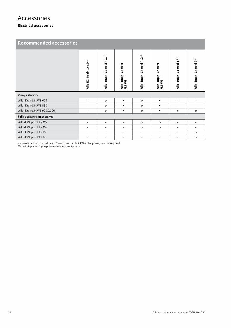
98 Subject to change without prior notice 09/2009 WILO SE
AccessoriesElectrical accessories
Recommended accessoriesAccessories Electrical accessories Recommended accessories Subject to change without prior notice 09/2009 WILO SE Wilo catalogue C 3.1 - 50 Hz – Pumps stations and solids separation system
Wilo
EC-
Drain
1x4.0
1)
Wilo
-Drain
-Control
PL1
1)
Wilo
-Drain
-Control
PL1
WS 1)
Wilo
-Drain
-Control
PL2
2)
Wilo
-Drain
-Control
PL2
WS 2)
Wilo
-Drain
-Control
1 1)
Wilo
-Drain
-Control
2 2)
Pumps stations
Wilo-DrainLift WS 625 - � • � • - -
Wilo-DrainLift WS 830 - � • � • - -
Wilo-DrainLift WS 900/1100 - � • � • � �
Solids separation systems
Wilo-EMUport FTS MS - - - � � - -
Wilo-EMUport FTS MG - - - � � - -
Wilo-EMUport FTS FS - - - - - - �
Wilo-EMUport FTS FG - - - - - - �
• = recommended, � = optional, o* = optional (up to 4 kW motor power), - = not required1)= switchgear for 1 pump, 2)= switchgear for 2 pumps
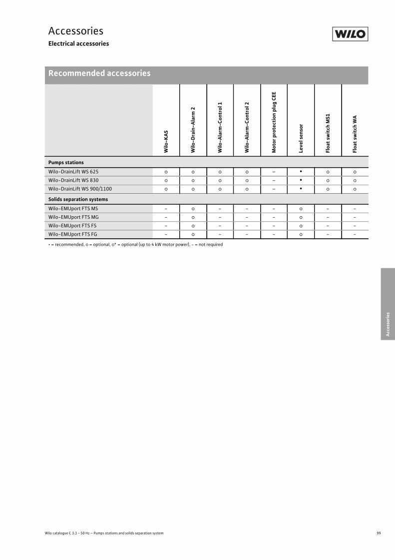
99
AccessoriesElectrical accessories
Wilo catalogue C 3.1 - 50 Hz – Pumps stations and solids separation system
Recommended accessories
Accessories
Accessories Electrical accessories Recommended accessories Subject to change without prior notice 09/2009 WILO SE Wilo catalogue C 3.1 - 50 Hz – Pumps stations and solids separation system
Wilo
-KAS
Wilo
-Drain
-Alarm
2
Wilo
-Alarm
-Control
1
Wilo
-Alarm
-Control
2
Motor
protection plug
CEE
Level sensor
Float switch MS1
Float switch
WA
Pumps stations
Wilo-DrainLift WS 625 � � � � – • � �
Wilo-DrainLift WS 830 � � � � – • � �
Wilo-DrainLift WS 900/1100 � � � � – • � �
Solids separation systems
Wilo-EMUport FTS MS - � - - - � - -
Wilo-EMUport FTS MG - � - - - � - -
Wilo-EMUport FTS FS - � - - - � - -
Wilo-EMUport FTS FG - � - - - � - -
• = recommended, � = optional, �* = optional (up to 4 kW motor power), - = not required

100 Subject to change without prior notice 09/2009 WILO SE
AccessoriesElectrical accessories
Recommended accessoriesAccessories Electrical accessories Recommended accessories Subject to change without prior notice 09/2009 WILO SE Wilo catalogue C 3.1 - 50 Hz – Pumps stations and solids separation system
Dynamic
pressure system
Bubbling-through system
Ex-rated
cut
-off
relay
Zener barrier
Switch cabinet
Flash light
Signal
horn
Pumps stations
Wilo-DrainLift WS 625 � � � � � � �
Wilo-DrainLift WS 830 � � � � � � �
Wilo-DrainLift WS 900/1100 � � � � � � �
Solids separation systems
Wilo-EMUport FTS MS - - - - � � �
Wilo-EMUport FTS MG - - - - - - -
Wilo-EMUport FTS FS - - - - � � �
Wilo-EMUport FTS FG - - - - - - -
• = recommended, � = optional, - = not necessary
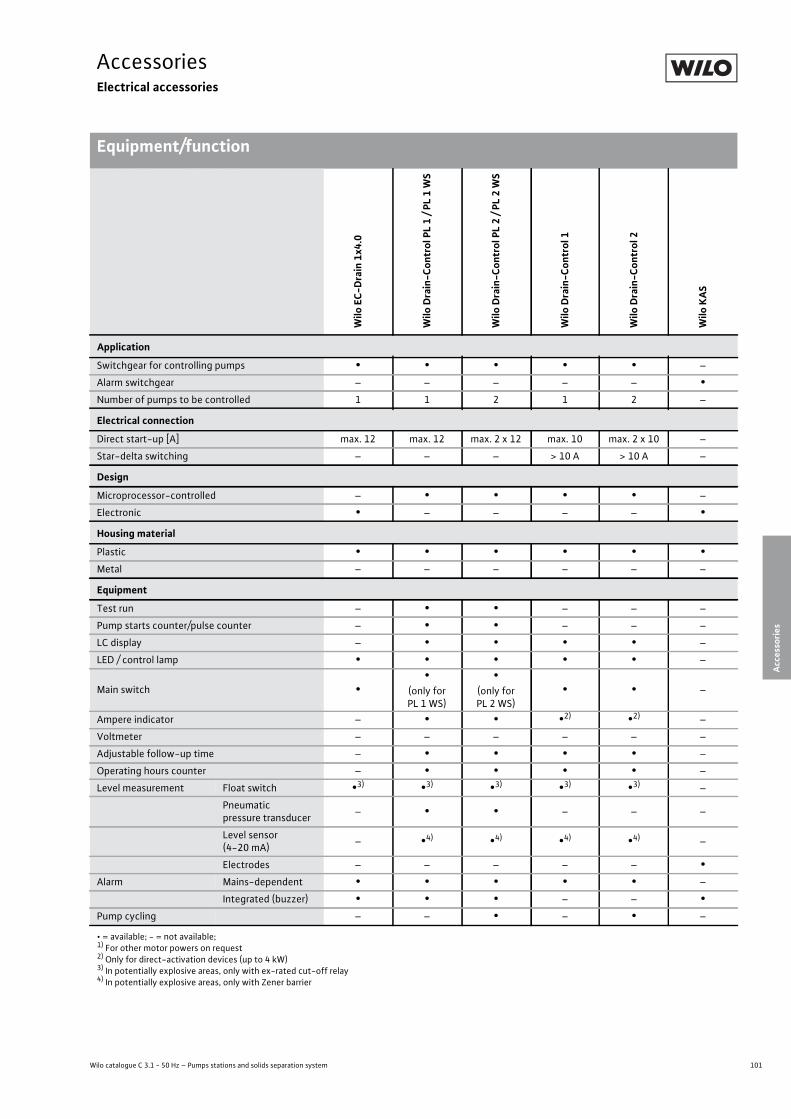
101
AccessoriesElectrical accessories
Wilo catalogue C 3.1 - 50 Hz – Pumps stations and solids separation system
Equipment/function
Accessories
Accessories Electrical accessories Equipment/function Subject to change without prior notice 09/2009 WILO SE Wilo catalogue C 3.1 - 50 Hz – Pumps stations and solids separation system
Wilo
EC-
Drain
1x4.0
Wilo
Drain
-Control
PL 1 / P
L 1
WS
Wilo
Drain
-Control
PL 2 / P
L 2
WS
Wilo
Drain
-Control
1
Wilo
Drain
-Control
2
Wilo
KAS
Application
Switchgear for controlling pumps • • • • • –
Alarm switchgear – – – – – •Number of pumps to be controlled 1 1 2 1 2 –
Electrical connection
Direct start-up [A] max. 12 max. 12 max. 2 x 12 max. 10 max. 2 x 10 –
Star-delta switching – – – > 10 A > 10 A –
Design
Microprocessor-controlled – • • • • –
Electronic • – – – – •Housing material
Plastic • • • • • •Metal – – – – – –
Equipment
Test run – • • – – –
Pump starts counter/pulse counter – • • – – –
LC display – • • • • –
LED / control lamp • • • • • –
Main switch ••
(only for PL 1 WS)
•(only for PL 2 WS)
• • –
Ampere indicator – • • •2) •2) –
Voltmeter – – – – – –
Adjustable follow-up time – • • • • –
Operating hours counter – • • • • –
Level measurement Float switch •3) •3) •3) •3) •3) –
Pneumaticpressure transducer – • • – – –
Level sensor(4-20 mA) – •4) •4) •4) •4) –
Electrodes – – – – – •Alarm Mains-dependent • • • • • –
Integrated (buzzer) • • • – – •Pump cycling – – • – • –
• = available; - = not available;1) For other motor powers on request2) Only for direct-activation devices (up to 4 kW)3) In potentially explosive areas, only with ex-rated cut-off relay4) In potentially explosive areas, only with Zener barrier
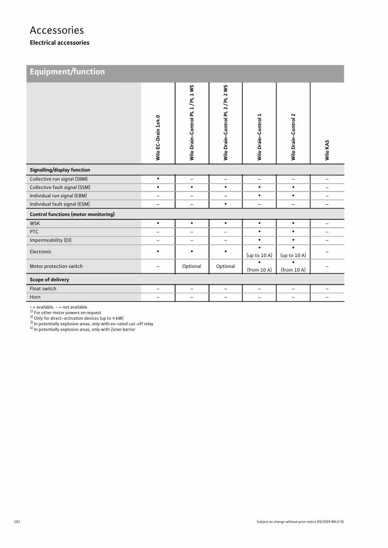
102 Subject to change without prior notice 09/2009 WILO SE
AccessoriesElectrical accessories
Equipment/functionAccessories Electrical accessories Equipment/function Subject to change without prior notice 09/2009 WILO SE Wilo catalogue C 3.1 - 50 Hz – Pumps stations and solids separation system
Wilo
EC-
Drain
1x4.0
Wilo
Drain
-Control
PL 1 / P
L 1
WS
Wilo
Drain
-Control
PL 2 / P
L 2
WS
Wilo
Drain
-Control
1
Wilo
Drain
-Control
2
Wilo
KAS
Signalling/display function
Collective run signal (SBM) • – – – – –
Collective fault signal (SSM) • • • • • –
Individual run signal (EBM) – – – • • –
Individual fault signal (ESM) – – • – – –
Control functions (motor monitoring)
WSK • • • • • –
PTC – – – • • –
Impermeability (DI) – – – • • –
Electronic • • • •(up to 10 A)
•(up to 10 A)
–
Motor protection switch – Optional Optional•
(from 10 A)•
(from 10 A)–
Scope of delivery
Float switch – – – – – –
Horn – – – – – –
• = available, - = not available1) For other motor powers on request 2) Only for direct-activation devices (up to 4 kW)3) In potentially explosive areas, only with ex-rated cut-off relay4) In potentially explosive areas, only with Zener barrier

103
AccessoriesElectrical accessories
Wilo catalogue C 3.1 - 50 Hz – Pumps stations and solids separation system
Equipment/function
Accessories
Accessories Electrical accessories Equipment/function Subject to change without prior notice 09/2009 WILO SE Wilo catalogue C 3.1 - 50 Hz – Pumps stations and solids separation system
Wilo
Drain
-Alarm
2
Wilo
Alarm
-Control
1
Wilo
Alarm
-Control
2
Motor
protection plug
CEE
Ex-rated
cut
-off
relay
Zener barrier
Flash light
Signal
horn
Wilo
SK
545
Application
Switchgear for controlling pumps – – – • – – – – –
Alarm switchgear • • • – – – – – –
Number of pumps to be controlled – – – 1 – – – – 2
Electrical connection
Direct start-up [A] – – – • – – – –
–External power section
Star-delta switching – – – – – – – –
–External power section
Design
Electronic • • • – • • • – •Electromechanical – – – • – – – • –
Housing materialPlastic • • • • • • • • •Equipment
LED / control lamp • – – • • – – – •Level measurement Float switch • • • • • – – – –
Pneumaticpressure transducer – – – – – – –
Level sensor(4-20 mA) – – – – – • – – –
Electrodes – – – – – – – – –
Alarm Independent of mains • • • – – – – – –
Mains-dependent • • • – – – – – –
Integrated (buzzer) • • • – – – – – –
Socket 1~230 V – – • – – – – – –
Signalling/display function
Individual fault signal (ESM) • • – – – – – – –
Control functions (motor monitoring)
WSK – – – • – – – – •Impermeability (DI) – – – – – – – – •Motor protection switch – – – • – – – – –
• = available, - = not available
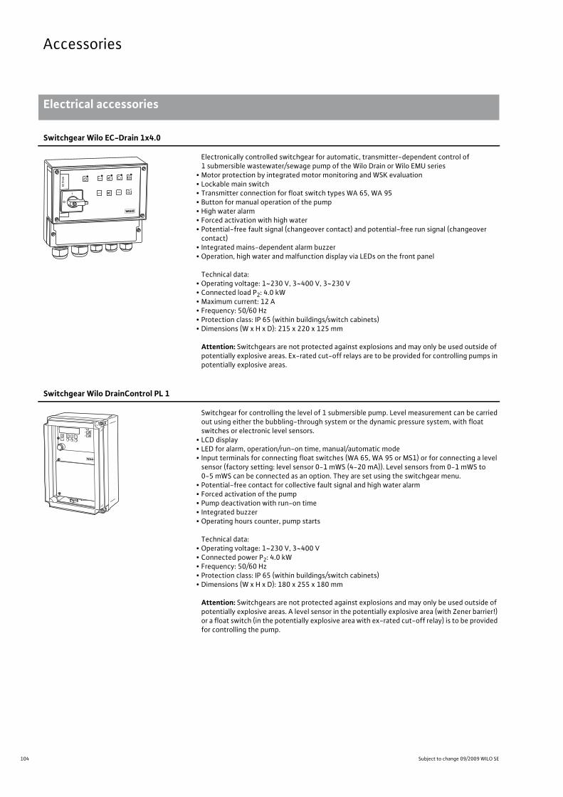
104 Subject to change 09/2009 WILO SE
Accessories
Electrical accessories
Accessories Electrical accessories Subject to change 09/2009 WILO SE Wilo catalogue C 3.1 - 50 Hz – Pumps stations and solids separation system
Switchgear Wilo EC-Drain 1x4.0
Electronically controlled switchgear for automatic, transmitter-dependent control of 1 submersible wastewater/sewage pump of the Wilo Drain or Wilo EMU series
• Motor protection by integrated motor monitoring and WSK evaluation• Lockable main switch• Transmitter connection for float switch types WA 65, WA 95• Button for manual operation of the pump• High water alarm• Forced activation with high water• Potential-free fault signal (changeover contact) and potential-free run signal (changeover contact)
• Integrated mains-dependent alarm buzzer• Operation, high water and malfunction display via LEDs on the front panel
Technical data:• Operating voltage: 1~230 V, 3~400 V, 3~230 V• Connected load P2: 4.0 kW• Maximum current: 12 A• Frequency: 50/60 Hz• Protection class: IP 65 (within buildings/switch cabinets)• Dimensions (W x H x D): 215 x 220 x 125 mm
Attention: Switchgears are not protected against explosions and may only be used outside of potentially explosive areas. Ex-rated cut-off relays are to be provided for controlling pumps in potentially explosive areas.
Switchgear Wilo DrainControl PL 1
Switchgear for controlling the level of 1 submersible pump. Level measurement can be carried out using either the bubbling-through system or the dynamic pressure system, with float switches or electronic level sensors.
• LCD display• LED for alarm, operation/run-on time, manual/automatic mode• Input terminals for connecting float switches (WA 65, WA 95 or MS1) or for connecting a level sensor (factory setting: level sensor 0-1 mWS (4-20 mA)). Level sensors from 0-1 mWS to 0-5 mWS can be connected as an option. They are set using the switchgear menu.
• Potential-free contact for collective fault signal and high water alarm• Forced activation of the pump• Pump deactivation with run-on time• Integrated buzzer• Operating hours counter, pump starts
Technical data:• Operating voltage: 1~230 V, 3~400 V• Connected power P2: 4.0 kW• Frequency: 50/60 Hz• Protection class: IP 65 (within buildings/switch cabinets)• Dimensions (W x H x D): 180 x 255 x 180 mm
Attention: Switchgears are not protected against explosions and may only be used outside of potentially explosive areas. A level sensor in the potentially explosive area (with Zener barrier!) or a float switch (in the potentially explosive area with ex-rated cut-off relay) is to be provided for controlling the pump.
autooff rreseseett
auto

105
Accessories
Wilo catalogue C 3.1 - 50 Hz – Pumps stations and solids separation system
Electrical accessories
Accessories
Accessories Electrical accessories Subject to change 09/2009 WILO SE Wilo catalogue C 3.1 - 50 Hz – Pumps stations and solids separation system
Switchgear Wilo DrainControl PL 1-WS
Switchgear for controlling the level of 1 submersible pump. Level measurement can be carried out using either the bubbling-through system or the dynamic pressure system, with float switches or electronic level sensors.
• LCD display• LED for alarm, operation/run-on time, manual/automatic mode• Input terminals for connecting float switches (WA 65, WA 95 or MS1) or for connecting a level sensor (factory setting: level sensor 0-1 mWS (4-20 mA)). Level sensors from 0-1 mWS to 0-5 mWS can be connected as an option. They are set using the switchgear menu.
• Potential-free contact for collective fault signal and high water alarm• Forced activation of the pump• Pump deactivation with run-on time• Integrated buzzer• Operating hours counter, pump starts• Lockable main switch• 3~ mains, no neutral conductor required
Technical data:• Operating voltage: 1~230 V, 3~400 V• Connected power P2: 4.0 kW• Frequency: 50/60 Hz• Protection class: IP 65 (within buildings/switch cabinets)• Dimensions (W x H x D): 180 x 255 x 180 mm
Attention: Switchgears are not protected against explosions and may only be used outside of potentially explosive areas. A level sensor in the potentially explosive area (with Zener barrier!) or a float switch (in the potentially explosive area with ex-rated cut-off relay) is to be provided for controlling the pump.
autooff rreseseett
auto
Switchgear Wilo DrainControl PL 2
Switchgear for controlling the levels of 2 submersible pumps. Level measurement can be car-ried out using either the bubbling-through system or the dynamic pressure system, with float switches or electronic level sensors.
• LCD display, multi-language switching• LED for alarm, operation/run-on time, manual/automatic mode• Input terminals for connecting float switches (WA 65, WA 95 or MS1) or for connecting a level sensor (factory setting: level sensor 0-2.5 mWS (4-20 mA)). Level sensors from 0-1 mWS to 0-5 mWS can be connected as an option. They are set using the switchgear menu.
• Potential-free contacts for collective fault signal and high water alarm, malfunction pump 1, malfunction pump 2
• Forced activation of the pump• Pump deactivation with run-on time• Automatic fault-actuated switchover• Integrated buzzer• Operating hours counter, pump starts
Technical data:• Operating voltage: 1~230 V, 3~400 V• Connected power P2: 2x 4.0 kW• Frequency: 50/60 Hz• Protection class: IP 65 (within buildings/switch cabinets)• Dimensions (W x H x D): 320 x 300 x 120 mm
Attention: Switchgears are not protected against explosions and may only be used outside of potentially explosive areas. A level sensor in the potentially explosive area (with Zener barrier!) or a float switch (in the potentially explosive area with ex-rated cut-off relay) is to be provided for controlling the pump.
auto
off
resetP2
reset
auto
reset
P1
P2P1
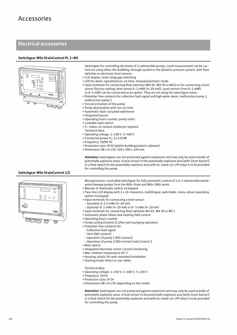
106 Subject to change 09/2009 WILO SE
Accessories
Electrical accessories
Accessories Electrical accessories Subject to change 09/2009 WILO SE Wilo catalogue C 3.1 - 50 Hz – Pumps stations and solids separation system
Switchgear Wilo DrainControl PL 2-WS
Switchgear for controlling the levels of 2 submersible pumps. Level measurement can be car-ried out using either the bubbling-through system or the dynamic pressure system, with float switches or electronic level sensors.
• LCD display, multi-language switching• LED for alarm, operation/run-on time, manual/automatic mode• Input terminals for connecting float switches (WA 65, WA 95 or MS1) or for connecting a level
sensor (factory setting: level sensor 0-1 mWS (4-20 mA)). Level sensors from 0-1 mWSto 0-5 mWS can be connected as an option. They are set using the switchgear menu.
• Potential-free contacts for collective fault signal and high water alarm, malfunction pump 1, malfunction pump 2
• Forced activation of the pump• Pump deactivation with run-on time• Automatic fault-actuated switchover• Integrated buzzer• Operating hours counter, pump starts• Lockable main switch• 3~ mains, no neutral conductor required
Technical data:• Operating voltage: 1~230 V, 3~400 V• Connected power P2: 2x 4.0 kW• Frequency: 50/60 Hz• Protection class: IP 65 (within buildings/switch cabinets)• Dimensions (W x H x D): 320 x 300 x 120 mm
Attention: Switchgears are not protected against explosions and may only be used outside of potentially explosive areas. A level sensor in the potentially explosive area (with Zener barrier!) or a float switch (in the potentially explosive area with ex-rated cut-off relay) is to be provided for controlling the pump.
auto
off
resetP2
reset
auto
reset
P1
P2P1
Switchgear Wilo DrainControl 1/2
Microprocessor-controlled switchgear for fully automatic control of 1 or 2 submersible waste-water/sewage pumps from the Wilo-Drain and Wilo-EMU series.
• Manual-0-Automatic switch via keypad• Two-line LCD display with 2 x 16 characters, multilingual, switchable, menu-driven operating
option via keypad• Input terminals for connecting a level sensor:
- Standard: 0-2.5 mWs (4-20 mA)- Optional: 0-1 mWs (4-20 mA) or 0- 5 mWs (4-20 mA)
• Input terminals for connecting float switches WA 65, WA 95 or MS 1• Automatic phase failure and rotating field control• Operating hours counter• Pump cycling (Control 2) after each pumping operation• Potential-free contacts for:
- Collective fault signal- Horn (NO contact)- Operation of pump 1 (NO contact)- Operation of pump 2 (NO contact) only Control 2
• Main switch• Integrated electronic motor current monitoring• Max. ambient temperature 40 °C• Housing: plastic for wall-mounted installation• Starting mode: Direct or star-delta
Technical data:• Operating voltage: 1~230 V, 3~400 V, 3~230 V• Frequency: 50 Hz• Protection class: IP 54• Dimensions (W x H x D): depending on the model
Attention: Switchgears are not protected against explosions and may only be used outside of potentially explosive areas. A level sensor in the potentially explosive area (with Zener barrier!) or a float switch (in the potentially explosive area with ex-rated cut-off relay) is to be provided for controlling the pump.
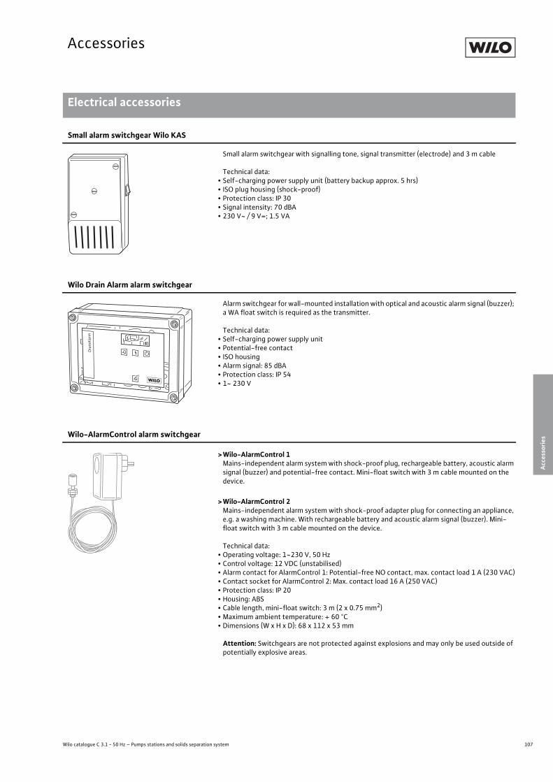
107
Accessories
Wilo catalogue C 3.1 - 50 Hz – Pumps stations and solids separation system
Electrical accessories
Accessories
Accessories Electrical accessories Subject to change 09/2009 WILO SE Wilo catalogue C 3.1 - 50 Hz – Pumps stations and solids separation system
Small alarm switchgear Wilo KAS
Small alarm switchgear with signalling tone, signal transmitter (electrode) and 3 m cable
Technical data:• Self-charging power supply unit (battery backup approx. 5 hrs)• ISO plug housing (shock-proof)• Protection class: IP 30• Signal intensity: 70 dBA• 230 V~ / 9 V=; 1.5 VA
Wilo Drain Alarm alarm switchgear
Alarm switchgear for wall-mounted installation with optical and acoustic alarm signal (buzzer); a WA float switch is required as the transmitter.
Technical data:• Self-charging power supply unit• Potential-free contact• ISO housing• Alarm signal: 85 dBA• Protection class: IP 54• 1~ 230 V
Wilo-AlarmControl alarm switchgear
>Wilo-AlarmControl 1Mains-independent alarm system with shock-proof plug, rechargeable battery, acoustic alarm signal (buzzer) and potential-free contact. Mini-float switch with 3 m cable mounted on the device.
>Wilo-AlarmControl 2Mains-independent alarm system with shock-proof adapter plug for connecting an appliance, e.g. a washing machine. With rechargeable battery and acoustic alarm signal (buzzer). Mini-float switch with 3 m cable mounted on the device.
Technical data:• Operating voltage: 1~230 V, 50 Hz• Control voltage: 12 VDC (unstabilised)• Alarm contact for AlarmControl 1: Potential-free NO contact, max. contact load 1 A (230 VAC)• Contact socket for AlarmControl 2: Max. contact load 16 A (250 VAC)• Protection class: IP 20• Housing: ABS• Cable length, mini-float switch: 3 m (2 x 0.75 mm2)• Maximum ambient temperature: + 60 °C• Dimensions (W x H x D): 68 x 112 x 53 mm
Attention: Switchgears are not protected against explosions and may only be used outside of potentially explosive areas.
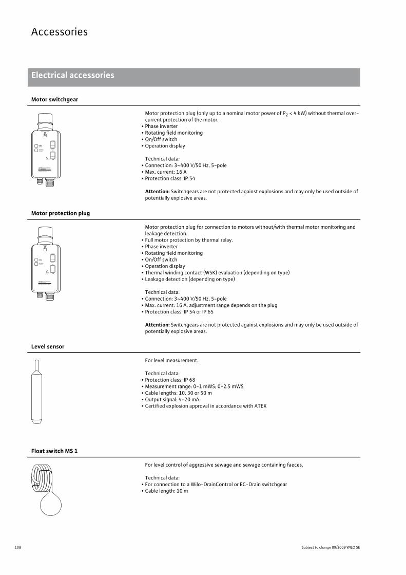
108 Subject to change 09/2009 WILO SE
Accessories
Electrical accessories
Accessories Electrical accessories Subject to change 09/2009 WILO SE Wilo catalogue C 3.1 - 50 Hz – Pumps stations and solids separation system
Motor switchgear
Motor protection plug (only up to a nominal motor power of P2 < 4 kW) without thermal over-current protection of the motor.
• Phase inverter• Rotating field monitoring• On/Off switch• Operation display
Technical data:• Connection: 3~400 V/50 Hz, 5-pole• Max. current: 16 A• Protection class: IP 54
Attention: Switchgears are not protected against explosions and may only be used outside of potentially explosive areas.
Motor protection plug
Motor protection plug for connection to motors without/with thermal motor monitoring and leakage detection.
• Full motor protection by thermal relay.• Phase inverter• Rotating field monitoring• On/Off switch• Operation display• Thermal winding contact (WSK) evaluation (depending on type)• Leakage detection (depending on type)
Technical data:• Connection: 3~400 V/50 Hz, 5-pole• Max. current: 16 A, adjustment range depends on the plug• Protection class: IP 54 or IP 65
Attention: Switchgears are not protected against explosions and may only be used outside of potentially explosive areas.
Level sensor
For level measurement.
Technical data:• Protection class: IP 68• Measurement range: 0-1 mWS; 0-2.5 mWS• Cable lengths: 10, 30 or 50 m• Output signal: 4-20 mA• Certified explosion approval in accordance with ATEX
Float switch MS 1
For level control of aggressive sewage and sewage containing faeces.
Technical data:• For connection to a Wilo-DrainControl or EC-Drain switchgear• Cable length: 10 m
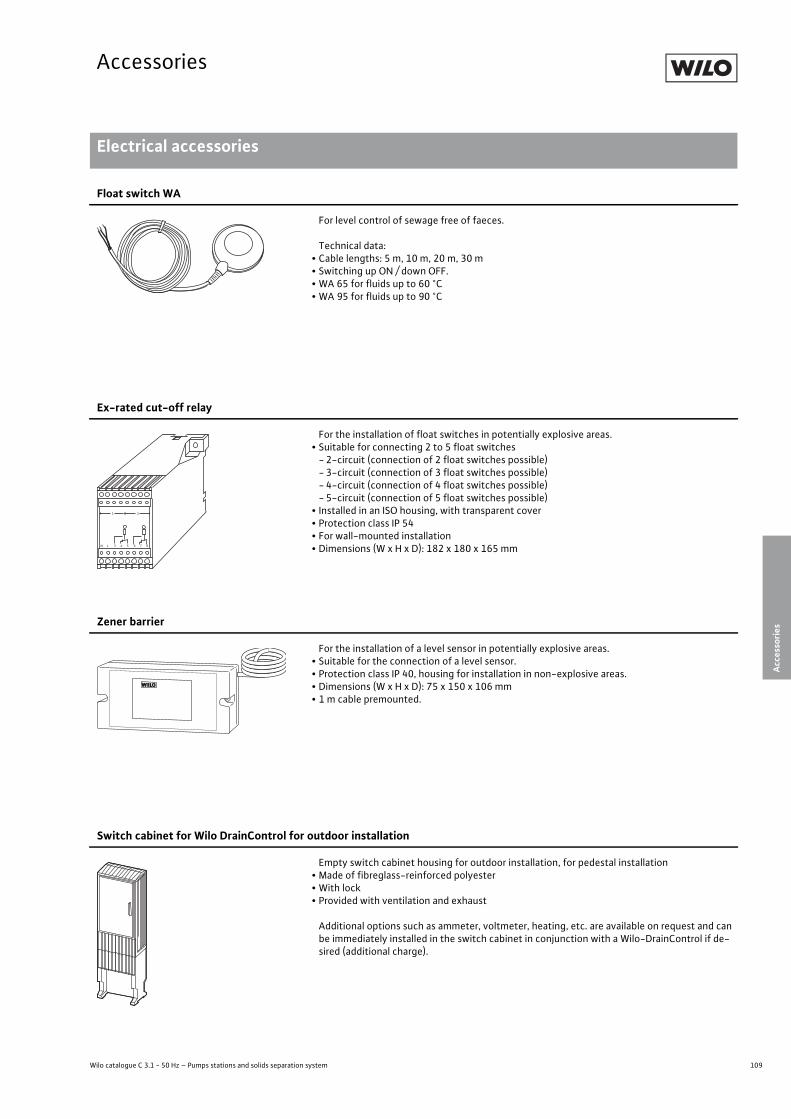
109
Accessories
Wilo catalogue C 3.1 - 50 Hz – Pumps stations and solids separation system
Electrical accessories
Accessories
Accessories Electrical accessories Subject to change 09/2009 WILO SE Wilo catalogue C 3.1 - 50 Hz – Pumps stations and solids separation system
Float switch WA
For level control of sewage free of faeces.
Technical data:• Cable lengths: 5 m, 10 m, 20 m, 30 m• Switching up ON / down OFF.• WA 65 for fluids up to 60 °C• WA 95 for fluids up to 90 °C
Ex-rated cut-off relay
For the installation of float switches in potentially explosive areas.• Suitable for connecting 2 to 5 float switches-2-circuit (connection of 2 float switches possible)-3-circuit (connection of 3 float switches possible)- 4-circuit (connection of 4 float switches possible)-5-circuit (connection of 5 float switches possible)
• Installed in an ISO housing, with transparent cover• Protection class IP 54• For wall-mounted installation• Dimensions (W x H x D): 182 x 180 x 165 mm
1 2
N L 3 4 5 6 7 8
Zener barrier
For the installation of a level sensor in potentially explosive areas.• Suitable for the connection of a level sensor.• Protection class IP 40, housing for installation in non-explosive areas.• Dimensions (W x H x D): 75 x 150 x 106 mm• 1 m cable premounted.
Switch cabinet for Wilo DrainControl for outdoor installation
Empty switch cabinet housing for outdoor installation, for pedestal installation• Made of fibreglass-reinforced polyester• With lock• Provided with ventilation and exhaust
Additional options such as ammeter, voltmeter, heating, etc. are available on request and can be immediately installed in the switch cabinet in conjunction with a Wilo-DrainControl if de-sired (additional charge).
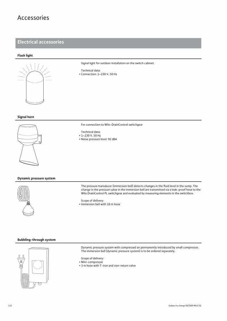
110 Subject to change 09/2009 WILO SE
Accessories
Electrical accessories
Accessories Electrical accessories Subject to change 09/2009 WILO SE Wilo catalogue C 3.1 - 50 Hz – Pumps stations and solids separation system
Flash light
Signal light for outdoor installation on the switch cabinet.
Technical data:• Connection: 1~230 V, 50 Hz
Signal horn
For connection to Wilo-DrainControl switchgear
Technical data:• 1~230 V, 50 Hz• Noise pressure level: 92 dBA
Dynamic pressure system
The pressure transducer (immersion bell) detects changes in the fluid level in the sump. The change in the pressure value in the immersion bell are transmitted via a leak-proof hose to the Wilo DrainControl PL switchgear and evaluated by measuring elements in the switchbox.
Scope of delivery:• Immersion bell with 10 m hose
Bubbling-through system
Dynamic pressure system with compressed air permanently introduced by small compressor. The immersion bell (dynamic pressure system) is to be ordered separately.
Scope of delivery:• Mini-compressor• 3 m hose with T-iron and non-return valve

111
Accessories
Wilo catalogue C 3.1 - 50 Hz – Pumps stations and solids separation system
Electrical accessories
Accessories
Accessories Electrical accessories Subject to change 09/2009 WILO SE Wilo catalogue C 3.1 - 50 Hz – Pumps stations and solids separation system
Tripping unit Wilo SK 545
Tripping unit for controlling a maximum of 2 Wilo submersible pumps, TP 80 or TP 100• Installation in existing switchgears or as a module for switchgears of conventional design, installation on a top-hat rail, 35 mm
• Monitoring of the rotating field• Leakage detection• Thermal monitoring (WSK)• Operating voltage: 3~ 400 V• Max. fuse protection: 6 A• Potential-free output contacts; max. load: 250 V, 1 A• Dimensions (W x H x D): 100 x 72 x 113 mm

1 Änderungen vorbehalten. WILO AG 09/2007
Heating, air-conditioning, coolingCirculation pumpsGlandless pumps and accessories, package heat exchanger assembly
Heating, air-conditioning, coolingGlanded pumpsPumps with in-line design and accessories
Heating, air-conditioning, cooling, water supplyMonobloc and norm pumps, axial split case pumpsPumps and accessories
Water supply Domestic water supply, rainwater utilisationPumps, systems and accessories
Water supply Borehole pumps, 3" to 24"Pumps and systems for building services, domestic, municipal and industrial water supply
Water supply High-pressure multistage centrifugal pumpsPumps and accessories
Water supply Pressure boosting systemsSingle-pump and multi-pump systems in dry well installations
Water supply Sprinkler pumps with VdS approvalBorehole pumps and accessories
Drainage and sewageDrainage pumpsSubmersible pumps, self-priming pumps and accessories
Drainage and sewageSewage pumps, DN 32 to DN 600Submersible pumps and accessories for building services, municipal and industrial applications
Drainage and sewageWastewater and sewage lifting units, pumps stationsPump systems and accessories
Drainage and sewageSubmersible mixersMixers, re-circulation pumps, jet cleaners, grit collector pumps and acces-sories for municipal application in water treatment systems
Catalogue A1
Catalogue A2
Catalogue A3
Catalogue B1
Catalogue B2
Catalogue B3
Catalogue B4
Catalogue B5
Catalogue C1
Catalogue C2
Catalogue C3
Catalogue C4
UMETechnologie
UMETechnologie
UMETechnologie
UMETechnologie
Heat
ing,
air-
cond
ition
ing,
cool
ing
Wat
ersu
pply
Dra
inag
ean
dse
wag
e
Wilo Catalogue Edition 2009
UMETechnologie
WILO SENortkirchenstraße 10044263 DortmundGermanyT 0231 4102-0F 0231 [email protected]
AlgeriaBad Ezzouar, Dar El BeidaT +213 21 [email protected]
Armenia375001 YerevanT +374 10 [email protected]
Bosnia and Herzegovina71000 SarajevoT +387 33 [email protected]
Georgia0179 TbilisiT +995 32 [email protected]
Macedonia1000 SkopjeT +389 2 [email protected]
Mexico07300 MexicoT +52 55 55863209roberto.valenzuela@ wilo.com.mx
Moldova2012 ChisinauT +373 2 [email protected]
Rep. MongoliaUlaanbaatarT +976 11 [email protected]
Tajikistan734025 DushanbeT +992 37 2232908farhod.rahimov@ wilo.tj
Turkmenistan744000 AshgabadT +993 12 [email protected]
Uzbekistan100015 TashkentT +998 71 [email protected]
November 2009
Wilo – International (Subsidiaries)
Wilo – International (Representation offices)
ArgentinaWILO SALMSONArgentina S.A.C1295ABI CiudadAutónoma de Buenos AiresT+ 54 11 4361 [email protected] PumpenÖsterreich GmbH1230 WienT +43 507 [email protected] Caspian LLC1065 BakuT +994 12 [email protected] Bel OOO220035 MinskT +375 17 [email protected] SA/NV1083 GanshorenT +32 2 [email protected] Bulgaria Ltd.1125 SofiaT +359 2 [email protected] Canada Inc.Calgary, Alberta T2A 5L4T +1 403 [email protected] China Ltd.101300 BeijingT +86 10 [email protected]
CroatiaWILO Hrvatska d.o.o.10090 ZagrebT +38 51 [email protected]
Czech RepublicWILO Praha s.r.o.25101 CestliceT +420 234 [email protected]
DenmarkWILO Danmark A/S2690 KarlslundeT +45 70 [email protected]
EstoniaWILO Eesti OÜ12618 TallinnT +372 [email protected]
FinlandWILO Finland OY02330 EspooT +358 [email protected]
FrancePompes Salmson78403 ChatouT +33 820 0000 [email protected]
Great BritainWILO (U.K.) Ltd.DE14 2WJ Burton-Upon-TrentT +44 1283 [email protected]
GreeceWILO Hellas AG14569 Anixi (Attika)T +302 10 [email protected]
HungaryWILO Magyarország Kft2045 Törökbálint(Budapest)T +36 23 [email protected]
IndiaWILO India Mather andPlatt Pumps Ltd.Pune 411019T +91 20 [email protected]
IndonesiaWILO Pumps IndonesiaJakarta Selatan 12140T +62 21 [email protected]
IrelandWILO Engineering Ltd.LimerickT +353 61 [email protected]
ItalyWILO Italia s.r.l.20068 PeschieraBorromeo (Milano)T +39 [email protected]
KazakhstanWILO Central Asia050002 AlmatyT +7 727 [email protected]
KoreaWILO Pumps Ltd.621-807 GimhaeGyeongnamT +82 55 [email protected]
LatviaWILO Baltic SIA1019 RigaT +371 67 [email protected]
LebanonWILO SALMSONLebanon12022030 El MetnT +961 4 [email protected] Lietuva UAB03202 VilniusT +370 5 [email protected] NetherlandsWILO Nederland b.v.1551 NA WestzaanT +31 88 9456 [email protected] Norge AS0975 OsloT +47 22 [email protected] Polska Sp. z.o.o.05-090 RaszynT +48 22 [email protected] Wilo-SalmsonPortugal Lda.4050-040 PortoT +351 22 [email protected] Romania s.r.l.077040 Com. ChiajnaJud. IlfovT +40 21 [email protected]
RussiaWILO Rus ooo123592 MoscowT +7 495 [email protected]
Saudi ArabiaWILO ME - RiyadhRiyadh 11465T +966 1 [email protected]
Serbia and MontenegroWILO Beograd d.o.o.11000 BeogradT +381 11 [email protected]
SlovakiaWILO Slovakia s.r.o.82008 Bratislava 28T +421 2 [email protected]
SloveniaWILO Adriatic d.o.o.1000 LjubljanaT +386 1 [email protected]
South AfricaSalmson South Africa1610 EdenvaleT +27 11 [email protected]
SpainWILO Ibérica S.A.28806 Alcalá de Henares(Madrid)T +34 91 [email protected]
SwedenWILO Sverige AB35246 VäxjöT +46 470 [email protected]
SwitzerlandEMB Pumpen AG4310 RheinfeldenT +41 61 [email protected]
TaiwanWILO-EMUTaiwanCo.Ltd.110 TaipehT +886 227 [email protected]
TurkeyWILO Pompa SistemleriSan. ve Tic. A.S.34530 IstanbulT +90 216 [email protected]
UkrainaWILO Ukraina t.o.w.01033 KiewT +38 044 [email protected]
United Arab EmiratesWILO Middle East FZEJebel Ali - DubaiT +971 4 886 [email protected]
USAWILO-EMU USA LLCThomasville,Georgia 31792T +1 229 [email protected]
WILO USA LLCMelrose Park, Illinois 60160T +1 708 [email protected]
VietnamWILO Vietnam Co Ltd.Ho Chi Minh City, VietnamT +84 8 [email protected]
WILO EMUPORT GmbHZechenstr. 5432429 MindenGermanyT 0571 5055070F 0571 [email protected]
Subject to change without prior notice. Our general terms of delivery and service apply (see www.wilo.de/agb)
2109039/1T/0909/EN/MP
WILO EMUPORT GmbHZechenstr. 5432429 MindenGermanyT 0571 5055070F 0571 [email protected]