setup linux iscsi system v1.0.1 - kirlew
TRANSCRIPT

Setup A distributed Computing System
using Linux, iSCSI and SANChris Kirlew
Overview1) Introduction2) Setup3) Installation of iSCSI4) Network
a. Verify channel-bondingb. Setup channel-bondingc. Setup Jumbo frames d. Redundant Gig-E switchese. Testing throughput
IntroductionCurrent technology has provided users with increased computing power at reduced costs. Since current servers are smaller, more powerful, and less costly than their predecessors, Server Rooms have evolved from large stand alone servers to rack mounted, distributed systems. The strength of the distributed system is in its redundancy. This type of architecture provides greater reliability which overcomes the lower reliability of individual components. i.e., architecture supersedes individual server quality. The distributed system architecture also allows for increases in computing power in smaller increments which lowers expansion costs. In the past when a server ran out of capacity it was replaced with a bigger ,higher capacity, server. However the bigger server was more expensive and the capacity usually exceeded what was needed in order accommodate future growth.There is also the factor of outages and what to do with the old server. Today a company can start with a basic two node, two SAN system and incrementally increase the server’s capacity to a 128 node, 32 SAN system. Infrastructure cost of growth can now be increased in smaller increments and smaller costs which reduces the timeframe for a company’s return on investment (ROI). Also the server downtime is reduced and in today’s computing world where many systems are 24 x 7 the previously
Setup a Distributed Computing System using Linux, iSCSI and SAN - Chris Kirlew
acceptable downtime needed to change servers is no longer practical. In the distributed Oracle RAC system I am discussing, no downtime is necessary to increase capacity. The Setup section lists the components used in setting up the e-commerce system I am discussing. This distributed rack mounted computer system consists of several commodity servers (rack mounted servers clustered together) and connected to Gigabit Ethernet (GigE) switches using two or more Network Interface Cards (NIC’s). Storage is located on Storage Area Networks (SAN’s) which have two or more connections to the GigE switches.
SetupThe following was used to setup the e-commerce system:5) 4 Dell commodity servers running RedHat ES3 (Linux 2.4 kernel)
•2 of the above servers were used for the Web service•2 for the database
6) Dual NICs were used on each server to access the network and provide network access redundancy
7) The network consists of four Gigabit Ethernet switches8) The SAN originally had one box (dual NICs and dual power supply) but was expanded
to two boxes, with 14 ATA IDE disks in each box.9) The two database servers ran Oracle 10g RAC databaseThe database servers accessed the SAN using the iSCSI protocol. Read/write access to the database files on the SAN by more than one server was possible with the use of the Oracle Cluster File System (ocfs).This system can be broken down into 3 subsystems; iSCSI, cluster and network. Lets now take a brief look at these subsystems. iSCSI
The movement away from servers with their own attached storage and towards the use of external storage arrays accessed by a server has resulted in several methods for accomplishing these remote connections. The most common methods are Myrinet and Infiniband which are excellent technologies but expensive, proprietary, and carry a steep learning curve. Also specialized and expensive switches and NIC’s are required, which limits these technologies to major corporations who can afford them. Due to the factors mentioned, another method was sought which would be cheaper and easier. This eventually led to the combining of two longtime and well known technologies, SCSI and TCP/IP.SCSI is a widely used method for allowing CPUs to access data on Hard Drives and TCP/IP Ethernet Networking is the standard network protocol for connecting computers. When combined the result is iSCSI. The appeal of this protocol lies in the use of the well
Page 2

Setup a Distributed Computing System using Linux, iSCSI and SAN - Chris Kirlew
understood and well supported TCP/IP. The iSCSI protocol uses a client-server architecture. A "client" (i.e.: the server OS ) is the initiator which creates requests and the "server" (i.e.: a storage device) is the target, which contains the data needed and answers requests from the initiator (i.e. client). The iSCSI protocol defines how to encapsulate SCSI commands and data requests into IP packets which are sent over an Ethernet connection; unpacks the IP packets; and creates a local stream of SCSI commands or data requests. The initial translation of information to iSCSI is performed by the “Initiator”.There are two types of Initiators: software and hardware. A hardware initiator is an iSCSI HBA, which is an ethernet card with a SCSI ASIC on-board to offload all the work from the system CPU. Adaptec is currently selling iSCSI HBA's which have Linux drivers available. These network cards can cost several hundred dollars per card but still represent a considerable saving over proprietary technologies. Since there is minimal cost involved in using a software initiator, that methodology was used and is the one that will be discussed.A software initiator is a driver that manages the pairing of the SCSI drivers together with the network interface driver. By using a software initiator most systems with an ethernet card can act as an iSCSI initiator. The initiator is located on a server and searches for available iSCSI targets provided by the “target” software package (located on the SAN). The “target” software can be used to build a SAN or a target server in a test environment. The assumption in made that the SAN was purchased from a reputable vendor who provides iSCSI capable SANs, therefore the target software is incorporated into the SAN operating system. Therefore the following pages will concentrate on the installation and use of the initiator software. The initiator software package and documentation can be downloaded from Sourceforge.orgCluster
The core of a distributed infrastructure is the use of cluster software. This software permits computers to pool resources to perform a given task and obtain the computing capacity of a much larger computer but keep the computing service independent of the reliability of each individual server. Servers can also be easily added or removed or switched from one cluster to another, thereby reducing the cost of growth and change in the Data Center. The result is a superior level of system availability, reliability, and flexibility. The most common cluster types are:
•High-performance clusters, also known as parallel or computational clusters and are generally used in systems that support large volumes of computational processing. In these clusters a parallel filesystem distributes processing resources across the nodes, which allows each node to access the same files at the same time via concurrent reads and writes. They are generally characterized by having one or a few “head” servers and many slave servers. The Beowulf Linux cluster, developed in the early 1990s by NASA, is the most familiar example.
Page 3
Setup a Distributed Computing System using Linux, iSCSI and SAN - Chris Kirlew
•High-availability (HA) clusters are designed for fault tolerance or redundancy. Since these clusters usually use two or more servers for processing, available servers are able to assume processing responsibilities for server(s) that have failed. This type of cluster is commonly found in the data-center and is thus the one used in Oracle 10g RAC.
•Load-leveling or load-balancing clusters distribute workload as evenly as possible across multiple servers (commonly web servers). Load balancing is also used in Oracle 10g RAC to distribute the workload of the database over the available servers.
Network
The iSCI and Oracle RAC systems are heavily dependent on a good network. The minimum network speed that should be used is Gigabit Ethernet (GigE). A GigE switch reduces the possibility of latency which affects the stability of the cluster connections and the iSCSI connections to the SANs. There are several protocols that can be used but GigE is preferred because it runs on any system that uses Ethernet, and many common GigE chipsets have Linux driver support. The more powerful 10GigE would be preferred and may eventually become the standard but is currently still new, expensive, and not supported by Linux. To provide redundancy and to reduce the loss of a server due to the failure of a NIC card or network switch, the use of channel bonding on each server is recommended. Channel bonding is the use of two or more network interfaces to form a virtual network interface with one MAC address. This allows the server to communicate using more than one NIC without creating address conflicts.
A. Installation of ISCSI
It's important to understand that iSCSI makes block devices available via the network. In general, block devices (disks) are mounted across an IP network to the local system and then used like any other block device. As with any other block device an iSCSI device can be partitioned, labeled, and a filesystem created on it. The operating system is able to read and write to the iSCSI device as if it was a local hard disk. This allows the use of any filesystem (EXT2/3, JFS, XFS, ReiserFS, etc.). The iSCSI connected device is handled as a block device and only one operating system can use the iSCSI device at a time unless a global filesystem, or read-only filesystem is used. The global filesystem will be created later using OCFS.All devices in an iSCSI enviroment have addresses and every address must be unique:Initiators will have addresses, and targets will also have addresses. When you define a target you can specify the address name yourself. When you use an initiator the address is typically defined for you. Below is a test setup used for this example. The following addresses are used:InitiatorName = iqn.1987-05.com.cisco:01.b711bbb384bd
Page 4
Setup a Distributed Computing System using Linux, iSCSI and SAN - Chris Kirlew
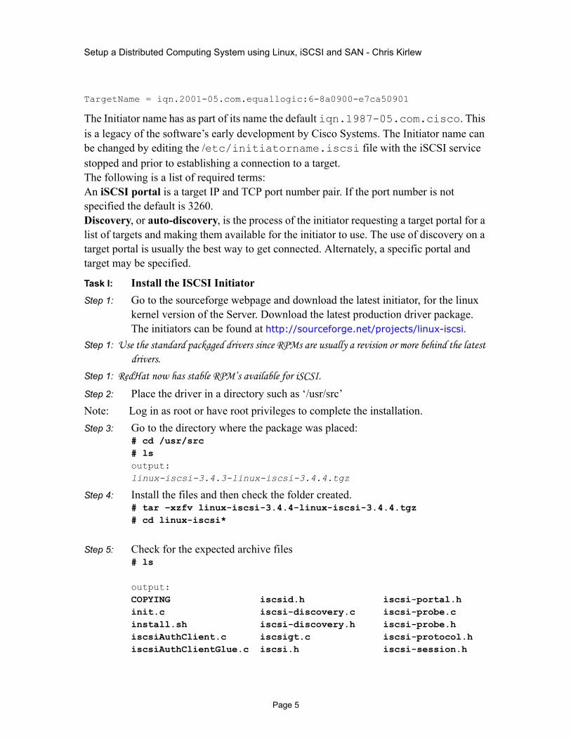
TargetName = iqn.2001-05.com.equallogic:6-8a0900-e7ca50901
The Initiator name has as part of its name the default iqn.1987-05.com.cisco. This is a legacy of the software’s early development by Cisco Systems. The Initiator name can be changed by editing the /etc/initiatorname.iscsi file with the iSCSI service stopped and prior to establishing a connection to a target.The following is a list of required terms:An iSCSI portal is a target IP and TCP port number pair. If the port number is not specified the default is 3260.Discovery, or auto-discovery, is the process of the initiator requesting a target portal for a list of targets and making them available for the initiator to use. The use of discovery on a target portal is usually the best way to get connected. Alternately, a specific portal and target may be specified.
Task I: Install the ISCSI InitiatorStep 1: Go to the sourceforge webpage and download the latest initiator, for the linux
kernel version of the Server. Download the latest production driver package. The initiators can be found at http://sourceforge.net/projects/linux-iscsi.
Step 1: Use the standard packaged drivers since RPMs are usually a revision or more behind the latest drivers.
Step 1: RedHat now has stable RPM’s available for iSCSI.
Step 2: Place the driver in a directory such as ‘/usr/src’Note: Log in as root or have root privileges to complete the installation.Step 3: Go to the directory where the package was placed:
# cd /usr/src# lsoutput:linux-iscsi-3.4.3-linux-iscsi-3.4.4.tgz
Step 4: Install the files and then check the folder created.# tar –xzfv linux-iscsi-3.4.4-linux-iscsi-3.4.4.tgz # cd linux-iscsi*
Step 5: Check for the expected archive files# ls
output:COPYING iscsid.h iscsi-portal.hinit.c iscsi-discovery.c iscsi-probe.cinstall.sh iscsi-discovery.h iscsi-probe.hiscsiAuthClient.c iscsigt.c iscsi-protocol.hiscsiAuthClientGlue.c iscsi.h iscsi-session.h
Page 5
Setup a Distributed Computing System using Linux, iSCSI and SAN - Chris Kirlew
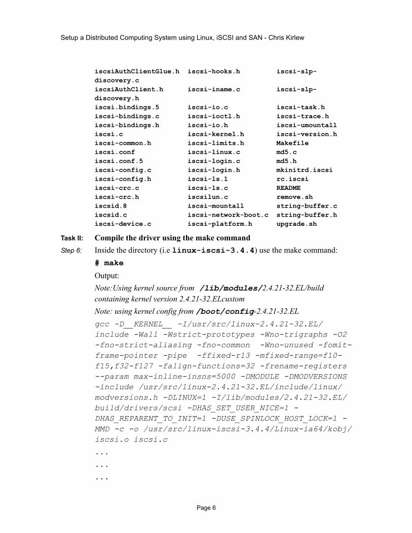
iscsiAuthClientGlue.h iscsi-hooks.h iscsi-slp-discovery.ciscsiAuthClient.h iscsi-iname.c iscsi-slp-discovery.hiscsi.bindings.5 iscsi-io.c iscsi-task.hiscsi-bindings.c iscsi-ioctl.h iscsi-trace.hiscsi-bindings.h iscsi-io.h iscsi-umountalliscsi.c iscsi-kernel.h iscsi-version.hiscsi-common.h iscsi-limits.h Makefileiscsi.conf iscsi-linux.c md5.ciscsi.conf.5 iscsi-login.c md5.hiscsi-config.c iscsi-login.h mkinitrd.iscsiiscsi-config.h iscsi-ls.1 rc.iscsiiscsi-crc.c iscsi-ls.c READMEiscsi-crc.h iscsilun.c remove.shiscsid.8 iscsi-mountall string-buffer.ciscsid.c iscsi-network-boot.c string-buffer.hiscsi-device.c iscsi-platform.h upgrade.sh
Task II: Compile the driver using the make commandStep 6: Inside the directory (i.e linux-iscsi-3.4.4) use the make command:
# make
Output:Note:Using kernel source from /lib/modules/2.4.21-32.EL/build containing kernel version 2.4.21-32.ELcustomNote: using kernel config from /boot/config-2.4.21-32.ELgcc -D__KERNEL__ -I/usr/src/linux-2.4.21-32.EL/include -Wall -Wstrict-prototypes -Wno-trigraphs -O2 -fno-strict-aliasing -fno-common -Wno-unused -fomit-frame-pointer -pipe -ffixed-r13 -mfixed-range=f10-f15,f32-f127 -falign-functions=32 -frename-registers --param max-inline-insns=5000 -DMODULE -DMODVERSIONS -include /usr/src/linux-2.4.21-32.EL/include/linux/modversions.h -DLINUX=1 -I/lib/modules/2.4.21-32.EL/build/drivers/scsi -DHAS_SET_USER_NICE=1 -DHAS_REPARENT_TO_INIT=1 -DUSE_SPINLOCK_HOST_LOCK=1 -MMD -c -o /usr/src/linux-iscsi-3.4.4/Linux-ia64/kobj/iscsi.o iscsi.c
...
...
...
Page 6

Setup a Distributed Computing System using Linux, iSCSI and SAN - Chris Kirlew
Task III: Install the driver with the make install commandStep 7: Enter the following command:
# make install
Output:Note: using kernel source from /lib/modules/2.4.21-32.EL/build containing kernel version 2.4.21-32.ELcustomNote: Using kernel config from /boot/config-2.4.21-32.ELInstalling iSCSI driver for Linux 2.4.21-32.ELThe initialization script has been installed as /etc/rc.d/init.d/iscsi.iSCSI is set up to run automatically when you reboot
InitiatorName iqn.1987-05.com.cisco:01.1b61d6f98cf was generated andwritten to /etc/initiatorname.iscsi.Reinstalling configuration file /etc/iscsi.conf
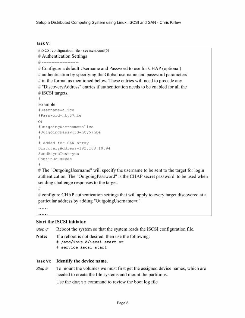
Task IV: Modify /etc/iscsi.conf fileEdit the iscsi.conf file so that the initiator points to the address of the array. It should resemble the file below. Add the lines displayed in bold and highlighted in yellow below to the file or edit the existing lines in the file. Placement in the file is not critical. The example lines use the IP address of 192.168.10.94 (replace this with the IP address of the array).The entire iscsi.conf file is not shown. For more information on other configuration options, consult the README included with the initiator drivers.# cd /etc# vi iscsi.conf
Page 7
Setup a Distributed Computing System using Linux, iSCSI and SAN - Chris Kirlew
Task V:
Start the ISCSI initiator. Step 8: Reboot the system so that the system reads the iSCSI configuration file.Note: If a reboot is not desired, then use the following:
# /etc/init.d/iscsi start or # service iscsi start
Task VI: Identify the device name.Step 9: To mount the volumes we must first get the assigned device names, which are
needed to create the file systems and mount the partitions.Use the dmesg command to review the boot log file
# iSCSI configuration file - see iscsi.conf(5)# Authentication Settings# -----------------------# Configure a default Username and Password to use for CHAP (optional)# authentication by specifying the Global username and password parameters# in the format as mentioned below. These entries will need to precede any# "DiscoveryAddress" entries if authentication needs to be enabled for all the# iSCSI targets.#
Example:#Username=alice#Password=nty57nbe
or#OutgoingUsername=alice#OutgoingPassword=nty57nbe# # added for SAN arrayDiscoveryAddress=192.168.10.94SendAsyncText=yes Continuous=yes #
# The "OutgoingUsername" will specify the username to be sent to the target for login authentication. The "OutgoingPassword" is the CHAP secret password to be used when sending challenge responses to the target.# # configure CHAP authentication settings that will apply to every target discovered at a particular address by adding "OutgoingUsername=u".…………
Page 8
Setup a Distributed Computing System using Linux, iSCSI and SAN - Chris Kirlew
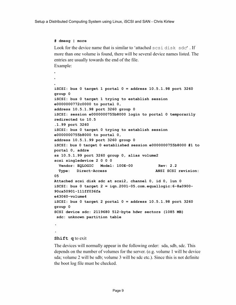
# dmesg | more
Look for the device name that is similar to ‘attached scsi disk sdc’. If more than one volume is found, there will be several device names listed. The entries are usually towards the end of the file.Example:...iSCSI: bus 0 target 1 portal 0 = address 10.5.1.98 port 3260 group 0iSCSI: bus 0 target 1 trying to establish session e0000000772c0000 to portal 0, address 10.5.1.98 port 3260 group 0iSCSI: session e0000000755b8000 login to portal 0 temporarily redirected to 10.5.1.99 port 3260iSCSI: bus 0 target 0 trying to establish session e0000000755b8000 to portal 0, address 10.5.1.99 port 3260 group 0iSCSI: bus 0 target 0 established session e0000000755b8000 #1 to portal 0, address 10.5.1.99 port 3260 group 0, alias volume2scsi singledevice 2 0 0 0 Vendor: EQLOGIC Model: 100E-00 Rev: 2.2 Type: Direct-Access ANSI SCSI revision: 05Attached scsi disk sdc at scsi2, channel 0, id 0, lun 0iSCSI: bus 0 target 2 = iqn.2001-05.com.equallogic:6-8a0900-90ca50901-111ff036fae43060-volume4iSCSI: bus 0 target 2 portal 0 = address 10.5.1.98 port 3260 group 0SCSI device sdc: 2119680 512-byte hdwr sectors (1085 MB) sdc: unknown partition table
.
.
Shift q to exitThe devices will normally appear in the following order: sda, sdb, sdc. This depends on the number of volumes for the server. (e.g. volume 1 will be device sda; volume 2 will be sdb; volume 3 will be sdc etc.). Since this is not definite the boot log file must be checked.
Page 9

Setup a Distributed Computing System using Linux, iSCSI and SAN - Chris Kirlew
Task VII: Create new Linux (ext2, ext3 etc..) partition
Task VII:NOTE: If the entire volume is configured as one Linux partition, then this step is not necessary. Proceed to Task 8: “Create the file system”.If no unix files will be created on the SAN and the ocfs file system is to be installed instead then proceed to the section “Installation of OCFS”.
Step 10: Enter the following command:# fdisk /dev/sda
Answers to the menu options are noted in bold type.
Output:
The number of cylinders for this disk is set to 4427.There is nothing wrong with that, but this is larger than 1024,and could in certain setups cause problems with:1) software that runs at boot time (e.g., old versions of LILO)2) booting and partitioning software from other OSs (e.g., DOS FDISK, OS/2 FDISK)1) software that runs at boot time (e.g., old versions of LILO)
Command (m for help):Command (m for help): mCommand action Command action a toggle a bootable flag b edit bsd disklabel c toggle the dos compatibility flag d delete a partition l list known partition types m print this menu n add a new partition o create a new empty DOS partition table p print the partition table q quit without saving changes s create a new empty Sun disklabel t change a partition's system id u change display/entry units v verify the partition table w write table to disk and exit x extra functionality (experts only) Command (m for help): n
Page 10

Setup a Distributed Computing System using Linux, iSCSI and SAN - Chris Kirlew
Command action e extended p primary partition (1-4)
pPartition number (1-4): 1First cylinder (1-13320, default 1):Using default value 1Last cylinder or +size or +sizeM or +sizeK (1-13320, default 13320):Using default value 13320
Command (m for help): wThe partition table has been altered!
Calling ioctl() to re-read partition table.Syncing disks.
Task VIII: Create the file system Step 11: Enter the following command# mkfs /dev/sda
Output:
mke2fs 1.32 (09-Nov-2002)/dev/sda is entire device, not just one partition!Proceed anyway? (y,n) yFilesystem label=OS type: LinuxBlock size=4096 (log=2)Fragment size=4096 (log=2)1706880 inodes, 3409920 blocks170496 blocks (5.00%) reserved for the super userFirst data block=0105 block groups32768 blocks per group, 32768 fragments per group16256 inodes per groupSuperblock backups stored on blocks: 32768, 98304, 163840, 229376, 294912, 819200, 884736, 1605632, 2654208
Writing inode tables: done
Page 11

Setup a Distributed Computing System using Linux, iSCSI and SAN - Chris Kirlew
Writing superblocks and filesystem accounting information: done
This filesystem will be automatically checked every 35 mounts or180 days, whichever comes first. Use tune2fs -c or -i to override.
Task IX: Mount the file systemStep 12: Check the file system before adding using df or mount commands# df –k
Output:
Filesystem 1K-blocks Used Available Use% Mounted on/dev/md0 10315000 2099776 7691248 22% //dev/sdb4 45386 0 45386 0% /opt/dev/sda1 51082 8532 42550 17% /bootnone 1019184 0 1019184 0% /dev/shm/dev/md1 7740760 2751392 4596160 38% /u01
Step 13: Create mount point and verify or modify permissions on the directory for correct user and group access.
# mkdir /u02Step 14: Mount file system using the logical mount points that were created and noted in
the dmesg output. (e.g /dev/sdc)# mount /dev/sdc /u02Step 15: Verify by using the df –h command, that the output shows the expected
partition. # df –h
Output:
Filesystem 1K-blocks Used Available Use% Mounted on/dev/md0 10315000 2099776 7691248 22% //dev/sdb4 45386 0 45386 0% /opt/dev/sda1 51082 8532 42550 17% /bootnone 1019184 0 1019184 0% /dev/shm/dev/md1 7740760 2751392 4596160 38% /u01/dev/sdc 1057888 44768 1013120 5% /u02
Page 12

Setup a Distributed Computing System using Linux, iSCSI and SAN - Chris Kirlew
Task X: Modify /etc/fstab.iscsi Note: Make a copy of the /etc/fstab.iscsi to create a backup of the file in case there is
any editing errors or file corruption.# cp /etc/fstab.iscsi /etc/fstab.iscsi.bak
Step 16: Edit the file to add lines for each of the iscsi volumes and mount points so that they will automatically mount on startup or reboot.
# vi /etc/fstab.iscsi
Task XI: Edit the /etc/fstab file
Task XII: Reboot and verify that no errors appear on rebootStep 17: Enter the following command# reboot or# init 6 or# shutdown –r
# /etc/fstab.iscsi file for filesystems built on iscsi devices.## A typical entry here would look like:# /dev/iscsi/bus0/target0/lun0/disk /mnt ext2 defaults 0 0## Where /dev/iscsi/bus0/target0/lun0/disk is an iscsi device## Line added for SAN volumes /dev/sdc /u02 ext3 _netdev ## # See fstab(5) for further details on configuring devices.
.
./dev/sdc/u02 ext3 _netdev..
Page 13

Setup a Distributed Computing System using Linux, iSCSI and SAN - Chris Kirlew
Step 18: Redo df –k or mount to verify that the directory mounted and that the volume is correct:
# df –k
Output::Filesystem 1K-blocks Used Available Use% Mounted on/dev/md0 10315000 2099776 7691248 22% //dev/sdb4 45386 0 45386 0% /opt/dev/sda1 51082 8532 42550 17% /bootnone 1019184 0 1019184 0% /dev/shm/dev/md1 7740760 2751392 4596160 38% /u01/dev/sdc 1057888 44768 1013120 5% /u02
B. Setup Network Choosing a network interconnect is important and depends on your system requirements and your budget. If Ethernet is the choice for the network then Gigabit Ethernet is the preferred choice. If a faster protocol is needed then 10Gigabit Ethernet is available but, as stated earlier, there is a limited number of vendors, the cost is high, and the protocol is not supported by Linux 2.4 or 2.6 kernels. Also, most server motherboards do not support the 10GigE protocol at this time. However, support is provided by a few vendors and the 10GigE protocol is the preferred solution for certain situations.The setup discussed in this document is based on a GigE network. Most servers today have motherboards that support GigE and many are available with 64bit PCI GigE NICs. The GigE protocol is supported by both the Linux 2.4 and 2.6 kernels. The rise in data traffic for most modern systems can place a heavy load on the CPU since most network cards use the CPU to process the TCP/IP packets. The addition of iSCSI support also adds to this burden. The problem is due to GigE still being based on the standard Ethernet MTU (Maximum Transmission Unit) size of 1500 bytes. Each Ethernet packet causes an interrupt which is serviced by the CPU. At the maximum speed of the NIC this can amount to 80000 interrupts per second. To reduce this burden on the CPU a number of solutions are available. The first and easiest is the use of a larger MTU usually referred to as a “Jumbo Frame”. Most GigE NICs support MTU sizes up to 9000 bytes. Implementing Jumbo Frames should reduce the number of interrupts by up to a factor of 6. This will also require that the network switches support Jumbo Frames. I will explain later in this chapter how to reset the MTU to the larger size.The second way to reduce CPU processing of TCP packets is to offload the processing to a GigE NIC that handles the packet processing. This is usually referred to as TOE (TCP
Page 14

Setup a Distributed Computing System using Linux, iSCSI and SAN - Chris Kirlew
Off-Load Engine). A TOE helps to reduce the CPU load and reduce the number of interrupts. However, it does not do anything to reduce latency. The use of RDMA (Remote Direct Memory Access) NIC’s with TOE capabilities provides the necessary latency reduction. To further reduce the load on the CPU a third method is to use an HBA ( Host Bus Adapter ) that will handle the TCP processing and the iSCSI translation. These switches can be somewhat expensive but provide a real benefit in increased performance of the cluster.To ensure that there is no single point of failure in our setup we have used more than one server, dual SANs and several network switches. We can extend this redundancy by ensuring that each server is not lost simply due to a NIC card failure. To allow the use of two NIC cards with Linux, the use of “channel bonding” will be required. The setting of this protocol will be discussed later but I will briefly explain this function. Channel bonding is the combining of two or more network interfaces to one MAC address. Basically channel bonding enables two or more NIC cards to act as one network interface which simultaneously increases the bandwidth and provides redundancy. Without channel bonding there would be a network failure caused by multiple MAC addresses from the same server on the same network. Each server should have access to more than one network switch to provide redundancy and provide a second path to the other servers in the cluster and the SAN. All the switches should be interconnected. This will mean that a lot of ports will be used to provide switch interconnect. Therefore switches should have an adequate number of ports.To guard against the loss of a server due to the failure of a NIC card, network line or switch the use of more than one network connection to two or more switches is recommended. Most servers have slots for two NICS. However, if you wish to have network redundancy within a database cluster which is on one network plus have redundant access to other servers (i.e. web servers) on another network then two NICS for each network will be needed.
Page 15

Setup a Distributed Computing System using Linux, iSCSI and SAN - Chris Kirlew
Once channel bonding has been activated, the NIC’s will be able to share the same IP address. The full instruction on channel bonding can be found on the Linux server (assuming you installed the necessary docs) at /usr/src/linux-2.4/Documentation/networking/bonding.txtChannel bonding requires each cluster member to have two Ethernet devices installed. When it is loaded, the bonding module uses the MAC address of the first enslaved network device and assigns that MAC address to the other network device. In the configuration, shown by the diagram, there are two servers each attached to both switches. The switches have a connection to the outside or to a SAN. There is an ISL - Inter Switch Link between both switches. One and only one slave on each host is active at a time (mode=1), but all links are still monitored and the system can detect a failure of the active or backup links.The server uses its active interface until it goes down and then it switches to the new one until it goes down. In this example, the clusters fault tolerance is slightly affected by the expiration time of the switches' forwarding tables.Server one’s active interface is connected to one switch while Server two’s active interface is connected to the other switch. This setup will survive a failure of a single server, NIC card, cable, or switch. In the case of a switch failure one of the servers will be temporarily unreachable until the other switch expires its tables. After this interval the cluster system will be back at full capacity.
A. Verify Channel Bonding Support
Task XIII: Determine if ifenslave is installed and install if necessaryStep 19: Enter the following command
Page 16

Setup a Distributed Computing System using Linux, iSCSI and SAN - Chris Kirlew
# whereis ifenslaveStep 20: To install ifenslave:# gcc -Wall -Wstrict-prototypes -O -I/usr/src/linux/include ifenslave.c -o ifenslave
Task XIV: Check if installation supports bondingStep 21: To check if your version of Linux uses sysconfig or initscripts, and to get the
installed version enter the following command:$ rpm -qf /sbin/ifupStep 22: The system should return either "initscripts" or "sysconfig," followed by the
version number.Example: initscripts-7.31.18.EL-1. This is the package that provides your network initialization scripts.Step 23: Enter the following command to determine if the initscript or sysconfig
supports bonding:# grep ifenslave /sbin/ifupStep 24: If the system returns matches, then the initscripts or sysconfig has support for
bonding.
Step 25: To get a list of the bonding options enter the following command:
# /sbin/modinfo bonding
B. Setup Channel Bonding
Task XV: Create a bonding deviceStep 26: Add an alias line to create bonding devices in /etc/modules.conf:alias bond0 bondingalias eth0 e1000alias eth1 e1000This loads the bonding device with the bond0 interface name, as well as passes options to the bonding driver to configure it as an active- backup master device for the enslaved network interfaces.
Task XVI: Add bonding parametersStep 27: Check the module bonding parameters before adding them to the /etc/
modules.conf file. # /sbin/insmod bond0 miimon=100 mode=1Step 28: Look at /var/log/messages to see if any errors were created.# tail –f /var/log/messages
Page 17

Setup a Distributed Computing System using Linux, iSCSI and SAN - Chris Kirlew
The parameter miimon specifies in milliseconds how often link monitoring occurs. This verifies if a NIC is active.
Step 29: Verify that the network interfaces eth0 and eth1 support MII (Media-Independent Interface). Use the following command:
# ethtool eth0 | grep “Link detected:” Step 30: The system should return:Link detected: yesStep 31: The parameter mode has several values available:0 – 6. For fault tolerance use
mode=1.Step 32:All transmissions are sent and received from the same slave interface and NIC. The other
interface will be used only if the active slave interface fails.
Step 33: The updated /etc/modules.conf file should resemble the followingalias bond0 bondingoptions bonding miimon=100 mode=1The miimon parameter must be specified or there can be a severe degradation of network performance if a link fails.The mode default parameter is 0. This places the bonding driver in a round-robin mode. If a NIC fails the failed NIC will still be used by the driver. This will lead to a loss of the iSCSI connection, and if the iSCSI connection loss is long enough to activate the hang-check timer, the server will reboot.
Task XVII: Configure bonding device Step 1: To configure bonding device first enter the following command# ifconfig bond0 10.4.1.201 netmask 255.255.255.0 broadcast 10.4.1.255 up
Step 34: Add slave interfaces to the bond.# ifenslave bond0 eth0 eth1
Step 35: Test the network connections to determine if they are working as expected.Step 36: To make the settings permanent, create a configuraton file for the bonding
device and update the configuration files of the slave interfaces.
Task XVIII:Create configuration file for the bonding deviceStep 37: Create a network script for the bonding device.(ex. /etc/sysconfig/network-
scripts/ifcfg-bond0)
Page 18

Setup a Distributed Computing System using Linux, iSCSI and SAN - Chris Kirlew
Task XIX:
Edit the configuration files of the network devicesStep 38: Edit the /etc/sysconfig/network-scripts/ifcfg-eth? configuration file for both
eth0 and eth1. Add the “MASTER=” and “SLAVE=” lines to their files. For example:
Step 39: This enslaves eth0 to the bond0 master device. Repeat for the other network devices.
Step 40: Restart the server or network.Reboot the system for the changes to take effect or manually load the bonding device and restart the network. For example:
# /sbin/insmod /lib/modules/`uname - r`/kernel/drivers/net/bonding/bonding.o miimon=100 mode=1# /sbin/service network restart
Task XX: Check that bonding is workingStep 41: Enter the following command to check if bonding is working:# ifconfig
bond0 Link encap:Ethernet HWaddr 00:0B:0D:30:EE:0D inet addr:10.4.1.201 Bcast:10.4.1.255 Mask:255.255.255.0 UP BROADCAST RUNNING MASTER MULTICAST MTU:1500 Metric:1 RX packets:14675843 errors:0 dropped:0 overruns:0 frame:0
DEVICE=bond0 USERCTL=no ONBOOT=yes BROADCAST=10.4.1.255 NETWORK=10.4.1.0 NETMASK=255.255.255.0 GATEWAY=10.4.1.1IP ADDR=10.4.1.201
DEVICE=eth0USERCTL=no ONBOOT=yes MASTER=bond0 SLAVE=yes BOOTPROTO=none
Page 19

Setup a Distributed Computing System using Linux, iSCSI and SAN - Chris Kirlew
TX packets:15331356 errors:0 dropped:0 overruns:0 carrier:0 collisions:0 txqueuelen:1000 RX bytes:9593922960 (9149.4 Mb) TX bytes:10201693503 (9729.0 Mb) Base address:0xcc80 Memory:f9fc0000-f9fe0000
eth0 Link encap:Ethernet HWaddr 00:0B:0D:30:EE:0D inet addr:10.4.1.201 Bcast:10.4.1.255 Mask:255.255.255.0 UP BROADCAST RUNNING SLAVE MULTICAST MTU:1500 Metric:1 RX packets:25845732 errors:0 dropped:0 overruns:0 frame:0 TX packets:27578563 errors:0 dropped:0 overruns:0 carrier:0 collisions:0 txqueuelen:1000 RX bytes:9593922960 (9149.4 Mb) TX bytes:10201693503 (9729.0 Mb) Base address:0xcc80 Memory:f9fc0000-f9fe0000
eth1 Link encap:Ethernet HWaddr 00:0B:0D:30:EE:0D inet addr:10.4.1.201 Bcast:10.4.1.255 Mask:255.255.255.0 UP BROADCAST RUNNING SLAVE MULTICAST MTU:1500 Metric:1 RX packets:16457297 errors:0 dropped:0 overruns:0 frame:0 TX packets:17136743 errors:0 dropped:0 overruns:0 carrier:0 collisions:0 txqueuelen:1000 RX bytes:9593922960 (9149.4 Mb) TX bytes:10201693503 (9729.0 Mb) Base address:0xcc80 Memory:f9fc0000-f9fe0000
Task XXI: Verify network linkStep 42: Enter the following command to verify the network link:# mii-tool –v eth0Step 43: Output:eth0: negotiated 100baseTx-FD, link ok product info: vendor 00:50:43, model 2 rev 5 basic mode: autonegotiation enabled basic status: autonegotiation complete, link ok capabilities: 100baseTx-FD 100baseTx-HD 10baseT-FD 10baseT-HD advertising: 100baseTx-FD 100baseTx-HD 10baseT-FD 10baseT-HD flow-control link partner: 100baseTx-FD 100baseTx-HD 10baseT-FD 10baseT-HD
C. Setup Jumbo Frames
Task XXII: Determine if Jumbo Frames is supportedStep 44: When implementing Jumbo Frames ensure that the switches can support Jumbo
Frames then activate the Jumbo Frame support on the switches.Step 44:Refer to your switch documentation if needed to determine how to accomplish this adjustment.
Step 45: Check the SAN for Jumbo Frame support.
Page 20
Setup a Distributed Computing System using Linux, iSCSI and SAN - Chris Kirlew
Step 45:Almost all iSCSI SAN’s support Jumbo Frames and the vendor documentation should cover activation.
Step 46: Adjust the server NIC’s for the database nodes, on the internal network, for Jumbo Frames.
Step 47:Activate Jumbo Frames on the internal network only and not on the public network connection.
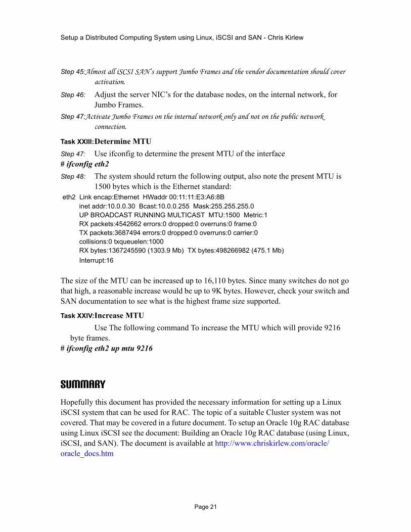
Task XXIII:Determine MTUStep 47: Use ifconfig to determine the present MTU of the interface# ifconfig eth2Step 48: The system should return the following output, also note the present MTU is
1500 bytes which is the Ethernet standard: eth2 Link encap:Ethernet HWaddr 00:11:11:E3:A6:8B inet addr:10.0.0.30 Bcast:10.0.0.255 Mask:255.255.255.0 UP BROADCAST RUNNING MULTICAST MTU:1500 Metric:1 RX packets:4542662 errors:0 dropped:0 overruns:0 frame:0 TX packets:3687494 errors:0 dropped:0 overruns:0 carrier:0 collisions:0 txqueuelen:1000 RX bytes:1367245590 (1303.9 Mb) TX bytes:498266982 (475.1 Mb) Interrupt:16
The size of the MTU can be increased up to 16,110 bytes. Since many switches do not go that high, a reasonable increase would be up to 9K bytes. However, check your switch and SAN documentation to see what is the highest frame size supported.
Task XXIV:Increase MTUUse The following command To increase the MTU which will provide 9216
byte frames.# ifconfig eth2 up mtu 9216
SummaryHopefully this document has provided the necessary information for setting up a Linux iSCSI system that can be used for RAC. The topic of a suitable Cluster system was not covered. That may be covered in a future document. To setup an Oracle 10g RAC database using Linux iSCSI see the document: Building an Oracle 10g RAC database (using Linux, iSCSI, and SAN). The document is available at http://www.chriskirlew.com/oracle/oracle_docs.htm
Page 21