setup guide - lexmark
TRANSCRIPT
Setup Guide

First Edition (June 1999)
The following paragraph does not apply to any country where such provisions are inconsistent with local law: LEXMARK INTERNATIONAL, INC., PROVIDES THIS PUBLICATION “AS IS” WITHOUT WARRANTY OF ANY KIND, EITHER EXPRESS OR IMPLIED, INCLUDING, BUT NOT LIM-ITED TO, THE IMPLIED WARRANTIES OF MERCHANTABILITY OR FITNESS FOR A PARTICULAR PURPOSE. Some states do not allow disclaimer of express or implied warranties in certain transactions; therefore, this statement may not apply to you.
This publication could include technical inaccuracies or typographical errors. Changes are periodically made to the information herein; these changes will be incorporated in later editions. Improvements or changes in the products or the programs described may be made at any time.
A form for the reader’s comments is provided at the back of this publication. If the form has been removed, comments may be addressed to Lexmark Inter-national, Inc., Department F95/035-3, 740 West New Circle Road, Lexington, Kentucky 40550, U.S.A. In the United Kingdom and Eire, send to Lexmark International Ltd., Marketing and Services Department, Westhorpe House, Westhorpe, Marlow Bucks SL7 3RQ. Lexmark may use or distribute any of the information you supply in any way it believes appropriate without incurring any obligation to you. You can purchase additional copies of publications related to this product by calling 1-800-553-9727. In the United Kingdom and Eire, call 0628-481500. In other countries, contact your point of purchase.
References in this publication to products, programs, or services do not imply that the manufacturer intends to make these available in all countries in which it operates. Any reference to a product, program, or service is not intended to state or imply that only that product, program, or service may be used. Any functionally equivalent product, program, or service that does not infringe any existing intellectual property right may be used instead.
Evaluation and verification of operation in conjunction with other products, programs, or services, except those expressly designated by the manufacturer, are the user’s responsibility.
Lexmark, MarkNet, MarkVision, and Optra are trademarks of Lexmark International, Inc., registered in the United States and/or other countries.
Other trademarks are the property of their respective owners.
© Copyright 1999 Lexmark International, Inc. All rights reserved.
UNITED STATES GOVERNMENT RESTRICTED RIGHTSThis software and documentation are provided with RESTRICTED RIGHTS. Use, duplication or disclosure by the Government is subject to restrictions as set forth in subparagraph (c)(1)(ii) of the Rights in Technical Data and Computer Software clause at DFARS 252.227-7013 and in applicable FAR provi-sions: Lexmark International, Inc., Lexington, KY 40550.
FCC Emissions Information
This device complies with Part 15 of the FCC Rules. Operation is subject to the following two conditions:
(1) this device may not cause harmful interference, and (2) this device must accept any interference received, including interference that may cause undesired operation.
Any questions on this statement should be directed to:
Director of Lab Operations Lexmark International, Inc.740 West New Circle Road NWLexington, KY 40550(606) 232-3000.
Please see the online User's Guide for further information.
Safety Information• If your product is NOT marked with this symbol , it MUST be connected to an electrical outlet that is properly grounded.
• The power cord must be connected to an electrical outlet that is near the product and easily accessible.
• Refer service or repairs, other than those described in the operating instructions, to a professional service person.
• This product is designed, tested and approved to meet strict global safety standards with the use of specific Lexmark components. The safety features of some parts may not always be obvious. Lexmark is not responsible for the use of other replacement parts.
• Your product uses a laser, exercise CAUTION: Use of controls or adjustments or performance of procedures other than those specified herein may result in hazardous radiation exposure.
• Your product uses a printing process that heats the print media, and the heat may cause the media to release emissions. You must understand the section in your operating instructions that discusses the guidelines for selecting print media to avoid the possibility of harmful emissions.

1
Getting Started
1 Select a well-ventilated place to set up your printer. Make sure you have a sturdy, low table or the optional printer stand on which to set the printer.
2 Remove all items from the box except the printer. If any items are missing, contact the place where you bought the printer.
Save the carton and packing material in case you need to repack the printer for ser-vice or storage.
Note: Leave the printer in the box until you are ready to install it. Then ask someone to help you lift the printer using the hand-holds.
Turn Off the Printer If your printer is already set up, make sure the printer power is off and the power cord and any cables are unplugged before installing any options.
Options Compatibility Options compatible with Optra™ T printers are labeled with a colored triangle. The location of the label is shown before each option install section.
Troubleshooting If you encounter a problem while setting up the printer, refer to the User’s Guide, available on the Optra T Publications CD, for more information.
137.16 cm (4 ½ ft)
304.8 mm (12 in.)
508 mm (20 in.)
304.8 mm (12 in.)
304.8 mm (12 in.)
CDs
Power cord
Printer
500-Sheet Drawer - Optra T616(n) and T614n models only
Paper bailand bracket
Operator panel overlay(non-English only)
Tray number decals - Optra T616(n) and T614n models only
Power switch cover
Handhold

Setup
5-Bin MailboxPage 12
Output ExpanderPage 10
PrinterPage 7
Duplex UnitPage 6
250-Sheet DrawerPage 5
500-Sheet DrawerPage 5
2000-Sheet DrawerPage 4
Option install order may be reversed.
*
*
Ord
er o
f Ins
talla
tion
Install Paper Options and Printer
*
Option CardsPage 17
Access printersystem board
Page 15
Install Memory and Option Cards
Load Paper
Attach Cables
Parallel Cable - Page 20
Serial Cable - Page 20
Power Cord - Page 21
Configure Network Printer
OS/2 Warp Server - Page 29
TCP/IP - Page 24
Novell NetWare - Page 28
AppleTalk - Page 29
See Page 23
1 2
4
5
6
3 See Page 19
Verify Setup
See Page 22
Printer/Flash MemoryPage 16
Envelope FeederPage 14
Print CartridgePage 9
High-Capacity Output StackerPage 14

3Install Paper Options and Printer
Step 1: Install Paper Optionsand Printer
Paper Options Supported The table illustrates various combinations of paper options supported by your printer. All models sup-port a duplex unit and envelope feeder.
Attach up to:3 output expanders,2 5-bin mailboxes,
1 of each, or1 high-capacity
output stacker, or 1 output expander and
1 high-capacityoutput stacker.
Does not supportoutput options
Attach up to: 3 additional optional
drawers
Attach up to:4 optional drawers
(Optra T614)3 additional optional drawers(Optra T614n ships with an
extra 500-sheet drawer)
Attach up to: 3 optionaldrawers
Attach up to: 3 optionaldrawers
Attach up to:3 output expanders,2 5-bin mailboxes,
1 of each, or1 high-capacity
output stacker, or 1 output expander and
1 high-capacityoutput stacker.
Output Expander 5-Bin MailboxHigh-Capacity Output Stacker
2000-Sheet Drawer 250-Sheet Drawer 500-Sheet Drawer Duplex Unit Envelope Feeder
Optra T616, T616n Optra T614, T614n Optra T612, T612n Optra T610, T610n
Attach up to:2 output expanders,1 5-bin mailbox, or
1 high-capacityoutput stacker.
INPUT
PRINTER
OUTPUT

4 Install Paper Options and Printer
Installing the 2000-Sheet Drawer Your printer supports one 2000-sheet drawer. It gives your printer added capacity by letting you load up to four reams (approximately 2,000 sheets) of 20 lb paper.
The 2000-sheet drawer is packaged with a User’s Guide that contains detailed instructions for instal-lation, setup and use, including loading paper and removing paper jams.
When you have finished installing the 2000-sheet drawer, install any drawers or a duplex unit that you have purchased.
Optra T label(colored triangle)

Install Paper Options and Printer 5
Installing a 250-Sheet or500-Sheet Drawer
Paper drawers attach under the printer and optional duplex unit. The printer automatically rec-ognizes any drawer that has been installed.
A drawer consists of a paper tray and a support unit. The 250-sheet drawer and the 500-sheet drawer are installed the same way.
1 Remove the tray from the support unit. Remove all packing material and tape from both the support unit and the tray.
2 Place the support unit on top of any previously installed paper drawers, or the table or printer cabinet where you plan to use the printer.
The tab, round hole and square holes on top of any drawer will help you seat the support unit so the edges are aligned properly. Make sure the support unit is securely in place.
At this point, attach another optional drawer, a duplex unit or the printer.
To attach a drawer, repeat steps 1 and 2.
To attach a duplex unit, see “Installing a Duplex Unit” on page 6.
To attach the printer, see “Placing the Printer” on page 7.
Optra T label(colored triangle)
Tray labels
Paper tray
Support unit
Tab
Round hole
Square hole

6 Install Paper Options and Printer
Installing a Duplex Unit The duplex unit attaches under the printer, below the standard input tray and above any paper drawers.
Refer to the printer User’s Guide, available on the Optra T Publications CD, for information on using the duplex unit.
1 Place the duplex unit on top of any installed paper drawers, or the table or printer cabinet where you plan to use the printer.
The tab, round hole and square holes on top of any drawer will help you seat the duplex unit so the edges are aligned properly. Make sure it is securely in place.
To attach the printer, see “Placing the Printer” on page 7.
Duplex unit for Optra T610(n) Duplex unit for Optra T616(n), T614(n) and T612(n)
(back cover curves inward)
Optra T label(colored triangle)
Back cover
Tab
Round hole
Square hole

Install Paper Options and Printer 7
Placing the Printer Note: In order to ensure adequate clearance when installing system board options, see “Install Memory and Optional Cards” on page 15 before you place the printer if you plan to:
• install memory or option cards
and
• will have less than 605.6 mm (24 in.) clearance on the left side of the printer.
Caution! Make sure your fingers are not under the printer when you set it down. Use the handholds on the printer or ask someone to help you lift it.
1 Ask someone to help you lift the printer by the handholds and lower it onto the duplex unit, optional drawer, table or printer cabinet.
The tab, round hole and square holes on top of any drawer or unit will help you seat the printer so the edges are aligned properly. Make sure the printer is securely in place.
To attach output options
If your printer supports output options, see:
• “Installing an Output Expander” on page 10
• “Installing a 5-Bin Mailbox” on page 12
• “Installing a High-Capacity Output Stacker” on page 14.
Handhold
Tab
Round hole
Square hole

8 Install Paper Options and Printer
Attaching the Paper Bail Note: Attach the paper bail to the top cover only if you do not plan to install a 5-bin mailbox as the top output option.
1 Remove the top cover of the printer and slide the plastic bracket onto the static brush holder. Adjust the bracket so it is centered over the exiting paper.
2 Place the tips of the wire paper bail into the ends of the plastic bracket so that the bail curves downward.
3 Replace the top cover.
Attaching Decals to Paper Trays Decals showing the number "1" are on your printer and the standard input tray as shown. These decals keep the standard input tray paired with the printer.
If you purchased an Optra T616(n) or T614n printer, or optional drawers, you received a sheet of decals.
Peel the decals from the sheet and attach them to the recessed areas on the drawer and the match-ing tray as shown.

Install Paper Options and Printer 9
Removing the Print Cartridge andPackaging
1 Push the release latch and open the upper front door of the printer.
2 Grasp the print cartridge by the handgrip and pull the print cartridge up and out.
3 Pull on each end of the plastic, V-shaped piece and then pull the packaging material straight out. Discard all packaging material.
. 4 Reinstall the print cartridge. Align the slides on the print cartridge with the slots on the print cartridge cradle. Use the colored arrows inside the printer for placement.
5 Guide the print cartridge down as it drops and snaps into place.
6 Close the upper front door.

10 Install Paper Options and Printer
Installing an Output Expander Each output expander consists of the expander and a removable tray. A paper bail, bracket, and labels are also included.
After you carefully unpack the output expander, install it immediately; otherwise, the edges of the mounting brackets could damage tabletops or fab-rics.
Warning! The output expander tray is designed to hold the weight of print material only. Do not use it as a shelf; excess weight may cause it to disengage from the output expander.
1 Remove the top cover from the printer or previously installed output option.
2 Slide the plastic bracket onto the static brush holder, located near the bottom of the output expander.
Optra T label(colored triangle)
Bracket and bail
Labels
Tray

Install Paper Options and Printer 11
3 Insert the mounting brackets into the slots on top of the printer or output option. Make sure the output expander is seated securely.
Note: Do not attach the paper bail unless you are mounting the output expander on the printer or another output expander.
4 Place the tips of the wire paper bail into the ends of the plastic bracket so that the bail curves downward.
The bail rests in the output tray of the expander below it, or in the printer output bin.
5 Slide the lower tabs on the tray into the lower slots on the output expander.
6 Rotate the tray up until the upper tabs click into the upper slots.
7 Attach the top cover to the output expander.
Mounting bracket
Mounting slot
Tabs
Slots

12 Install Paper Options and Printer
Installing a 5-Bin Mailbox The 5-bin mailbox is shipped with a sheet of labels and a plastic bracket for attaching a paper bail.
After you carefully unpack the 5-bin mailbox, install it immediately; otherwise, the edges of the mount-ing brackets could damage tabletops or fabrics.
Warning! The 5-bin mailbox is designed to hold the weight of print material only. Do not use it as a shelf; excess weight may damage it.
1 Remove the top cover from the printer or previously installed output expander or 5-bin mailbox.
2 Slide the plastic bracket onto the static brush holder, located near the bottom of the 5-bin mailbox.
Optra T label(colored triangle)
Labels
Bracket

Install Paper Options and Printer 13
3 Insert the mounting brackets into the slots on top of the printer, output expander or 5-bin mailbox. Make sure the 5-bin mailbox is seated securely.
Note: If the 5-bin mailbox will be the topmost output option, remove the paper bail from the bracket on the top cover and store in a safe place.
4 Attach the top cover to the 5-bin mailbox.
Note: Do not attach the paper bail unless you are mounting the 5-bin mailbox on the printer or an output expander.
5 Place the tips of the wire paper bail into the ends of the plastic bracket so that the bail curves downward.
The bail rests in the output tray of the expander below it, or in the printer output bin.
6 Adjust the paper stops for the paper size you will use.
Attaching Labels to OutputExpanders and 5-Bin Mailboxes
If you purchased an output expander or 5-bin mail-box, you received a sheet of labels. These labels are provided so that you may label your various output bins.
The illustration indicates some places where you may attach the labels: output bin tray, paper stop, side cover, or wherever best suits your application.
Mounting bracket
Mounting slot
Paper stops
Side cover
Paper stop
Labels
14 Install Paper Options and Printer
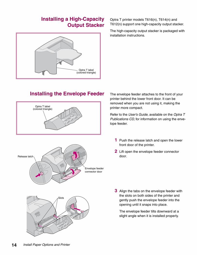
Installing a High-CapacityOutput Stacker
Optra T printer models T616(n), T614(n) and T612(n) support one high-capacity output stacker.
The high-capacity output stacker is packaged with installation instructions.
Installing the Envelope Feeder The envelope feeder attaches to the front of your printer behind the lower front door. It can be removed when you are not using it, making the printer more compact.
Refer to the User’s Guide, available on the Optra T Publications CD, for information on using the enve-lope feeder.
1 Push the release latch and open the lower front door of the printer.
2 Lift open the envelope feeder connector door.
3 Align the tabs on the envelope feeder with the slots on both sides of the printer and gently push the envelope feeder into the opening until it snaps into place.
The envelope feeder tilts downward at a slight angle when it is installed properly.
Optra T label(colored triangle)
Optra T label(colored triangle)
Envelope feeder connector door
Release latch
Slots

Install Memory and Optional Cards 15
Step 2: Install Memory and Optional Cards
Accessing the Printer System Board You must access the printer system board to install printer memory, flash memory, or an optional card.
1 Make sure the printer power is off, the printer power cord is unplugged, and all cables are disconnected from the back of the printer.
2 Press the release latches to open the upper and lower front doors.
3 Press down on the side door latches and open the side door.
4 Loosen, but do not remove, the six screws as shown.
Screws

16 Install Memory and Optional Cards
5 Use the tabs to slide the shield up until the top three screws fit into the three keyholes on the shield.
6 Hold the shield by the tabs and lift it off.
Installing Printer Memoryor Flash Memory
1 Follow the steps under “Accessing the Printer System Board” beginning on page 15.
Warning! Electronic components can be damaged by static electricity. Touch something metal on the printer before you touch the memory option.
2 Unpack the memory option. Avoid touching the connection points along its edge. Save the packaging materials.
3 Open both latches completely. Insert the memory option straight into the connector with the connection points pointing toward the system board as shown.
4 Push the memory card firmly into the connector until it snaps into place. Make sure each latch fits over the notch located on either side of the option card.
5 See “Reattach Shield and Close Doors” beginning on page 18 to reattach the shield and side door.
Keyhole
TabTab
Memory connector 1
Memory connector 2
Memory connector 3T616(n) and T614(n)
models only
Connection pointsLatch
Latch
Notch

Install Memory and Optional Cards 17
Installing an Optional Card A number of cards are available for your printer.
Refer to the documentation that is included with each card for detailed information about that spe-cific card.
Your printer will accommodate one or two cards, depending on the model. The installation instruc-tions are the same for each type of card.
Warning! Electronic components are easily damaged by static electricity. Touch something metal on the printer before you touch the card.
1 Before you install the card, follow the steps under “Accessing the Printer System Board” beginning on page 15.
2 Locate the card connectors on the system board. If you are installing only one card, install it in connector 1. If you are installing two cards on a model with multiple connectors, use connector 1 first and then connector 2.
3 Locate the two screws on the back of the printer that attach the metal plate to the slot.
4 Remove and save the two screws. Remove and discard the plate.
5 Unpack the card. Save the packaging materials.
MarkNet internal print server
Tri-Port interface
Hard disk with adapter
Parallel/USB interface
Connector 1Connector 2

18 Install Memory and Optional Cards
6 Align the connection points on the card with the connector on the system board and push them firmly into the system board connector.
7 Insert the two screws saved from the metal plate (or the extra screws shipped with the card) into the holes as shown.
8 Tighten the screws to secure the card.
Reattach Shield and Close Doors After you have installed card(s) on the printer sys-tem board, follow these steps to reattach the shield and close the doors.
1 Grasp the shield by the tabs and align the three keyholes on the shield with the top three screws. Holding the shield by the tabs, slide it down. Tighten all six screws.
2 Close the side door.
3 Close the upper and lower front doors.
Note: If you have not completed the section “Placing the Printer” beginning on page 7, do so now.
Tabs

Load Paper 19
Step 3: Load Paper
Loading a Paper Tray Complete these instructions to load print materials into any of the standard or optional trays. All paper trays are loaded in the same way.
1 Remove the paper tray.
2 Squeeze the width guide lever and slide the width guide to the far right side of the tray.
3 Squeeze the length guide lever and slide the length guide to the correct position for the size paper you are loading.
. 4 Place the paper into the paper tray with the recommended print side face down for single-sided printing and face up for double-sided printing. Do not fill paper above the paper capacity mark (fill line).
5 Squeeze the width guide lever and slide the width guide to the left until it lightly rests against the edge of the paper stack
6 Adjust the knob to show the size of the paper currently loaded.
Note: This setting serves as a visual reminder only; it has no effect on the operation of the printer.
7 Reinstall the tray.
Width guide
Squeeze here
Paper size indicators
Length guide
Length guide lever
Width guide
Squeeze here
Paper capacity mark
Knob

20 Attach Cables
Step 4: Attach Cables
Attaching a Parallel Cable To connect your printer to your computer with a parallel interface cable, use an IEEE 1284-compli-ant parallel cable that supports bidirectional com-munication.
Caution! Turn off and unplug all involved equipment before attaching the cable.
We recommend Lexmark part number 1329605 (10 ft) or 1427498 (20 ft). If you use something other than an IEEE-compliant cable, you may not be able to access all of your printer functions.
1 Align and plug the cable into the parallel connector as shown.
2 Snap the clips at each end of the connector down into the notches on the plug as shown.
3 Connect the other end of the parallel cable to the back of your computer. Tighten the screws on the parallel cable to the computer.
4 Check the parallel cable connections to make sure they are secure.
Attaching a Serial Cable If your printer is configured with a serial port, con-nect it to your computer with a null modem serial cable.
Caution! Turn off and unplug all involved equipment before attaching the cable.
We recommend Lexmark part number 1038693 (50 ft).
1 Align and plug the cable into the port on the back of your printer as shown.
2 Tighten both screws.
3 Connect the other end of the serial cable to the port on the back of your computer.
4 Check the cable connections to make sure they are secure.
Parallel connector
Clips
Serial connector

Attach Cables 21
Turning on the printer 1 Plug the printer power cord into the connec-tor as shown.
2 Plug the other end of the printer power cord into a properly grounded electrical outlet.
3 Turn the printer power on.
If an error message displays, refer to the troubleshooting section of the User’s Guide, available on the Optra T Publications CD.
Attaching the Operator Panel Overlay If English is not your preferred language, an over-lay with translated names for the operator panel buttons is included with the printer.
1 Peel the protective backing off the overlay.
2 Align the holes in the overlay with the buttons on the operator panel and press it into place.
3 Rub the overlay firmly to make sure it adheres securely to the operator panel.
4 Peel the protective covering away from the overlay.
Operator panel overlay

22 Verify Setup
Step 5: Verify Setup
Printing the MenuSettings Page
The menu settings page shows current settings for the menus and a list of installed options. You can use this page to verify that all printer options are properly installed and the printer settings are set to what you want.
Warning! Complete “Removing the Print Cartridge and Packaging” on page 9 before printing a page.
1 Make sure the printer power is on and the Ready status message appears on the display.
2 On the operator panel, press Menu> or <Menu to enter the menus.
3 Continue to press and release Menu> or <Menu until you see UTILITIES MENU.
4 Press Select.
5 Press Menu> until Print Menus appears on the second line of the display.
6 Press Select.
The message Printing Menu Settings appears on the operator panel display until the page prints, then the printer returns to the Ready state.
Note: If you receive a message, such as: 201 Paper Jam Remove Cartridgerefer to the User’s Guide on the Publications CD for more information.
7 Verify that the options you installed are listed on the menu settings page under “Installed Features.”
If an option you installed does not appear on the page, turn the printer off, unplug the power cord, and reinstall the option.
8 If you attached a serial cable, verify that the printer serial settings listed on the menu settings page are appropriate for your system.
Installing PrinterDrivers and Utilities
1 Locate the Drivers, MarkVision and Utilities CD.
2 Follow the instructions in the booklet included with the CD to start the printer setup utility appropriate for your operating system.

Configure Network Printer 23
Step 6: Configure Network Printer
If your Optra T printer is a network model or if you have installed a network option on a Optra T616, T614, T612, or T610, you can use the instructions in this step to attach and set up your printer on a network.
Attaching YourPrinter to the
Network
1 Turn the printer power off.
2 Plug the network cable into the network port.
3 Turn the printer power back on.
Note: If you installed a MarkNet™ print server that has more than one network port, use only one of the ports.
Printing a NetworkSetup Page
Use the printer operator panel to print the network setup page. (Hint: Network Menu, Standard Network, STD Net Setup, Print, Print Setup Page. Or, if you have a MarkNet card in slot x: Network Menu, Network Option x, Network x Setup, Print, Print Setup Page.)
The network setup page shows the printer physical address, known as the univer-sally administered address (UAA), of the print server and other important data. Look for the UAA under the Network heading on the setup page.
The UAA is a 12-digit number. The left column shows the address in MSB form and the right column shows the address in canonical form. Save this page to use later.
Note: The UAA is preset at the factory. However, you can override it with an optional locally administered address (LAA) if you want some particular physical address for this printer.

24 Configure Network Printer
Configuring andPrinting
Troubleshooting
For troubleshooting information, look on the Drivers, MarkVision and Utilities CD. Click View Documentation and look for the MarkNet link.
About the Drivers, MarkVision and Utilities CD
You may have more than one version of the Drivers, MarkVision and Utilities CD, received at different times with different Lexmark products. Always use the latest version CD.
TCP/IP Set the IP address, netmask, and gateway
You must assign an IP address, netmask, and gateway to the printer for other net-work devices to find it on the network.
• If you have DHCP, the proper address values are automatically assigned. To verify that the assignment has happened, print a network setup page and make sure the IP address, netmask and gateway appear as non-zero.
• If you don’t have DHCP, there are other methods you can use to manually assign the address such as the printer operator panel, static ARP and tel-net, RARP and telnet, BOOTP, or MarkVision™ or other Lexmark utility. Instructions for three of these methods follow.
Note: For instructions on other ways to set the IP address, look on the Drivers, MarkVision, and Utilities CD. Click View Documentation and look for the MarkNet link.
Printer operator panel
A simple way to set the IP address, netmask and gateway inside the printer is to use the printer operator panel. You need to be at the printer to use this method.
1 On the printer operator panel, choose Network Menu, Standard Network, STD Net Setup, TCP/IP, Set IP Address. Or, if you have a MarkNet™ card installed in slot x, choose Network Menu, Network Option x, Network Option x Setup, TCP/IP, Set IP Address. (Hint: Press Menu> until you see the correct menu item, and then press Select.)
2 When the current IP address is displayed, use the buttons to change the address. (Hint: Pressing Select advances you to the next segment in the address. Pressing Menu> increases the number by one. <Menu decreases the number by one.)
Network Environment Page
TCP/IP 24
Novell NetWare 28
AppleTalk 29
OS/2 Warp Server 29

Configure Network Printer 25
3 When you finish setting the IP address, press Select until the word SAVED appears briefly. Print a new network setup page to verify the parameters are set as you intended.
Static ARP and telnet
You can use this method from any Windows, OS/2, or UNIX workstation. You need to know the physical address of the printer to use this method. Also, your worksta-tion and the printer must be on the same subnet.
1 Find the physical address (UAA) of the printer (for example, 00200022012F) on the network setup page you printed earlier. If you have an Ethernet net-work, use the number in the right column (canonical). If you have a Token-Ring network, use the number in the left column (MSB).
2 Set the IP address in your workstation ARP table. At a command prompt, type a command line similar to the following, inserting the IP address you want to assign and the UAA:
arp -s 192.168.236.24 00-20-00-22-01-2F
3 Set the IP address, netmask and gateway in the printer. To do this, telnet to port 9000 on the printer by typing a command similar to the following:
telnet 192.168.236.24 9000
4 Verify that the printer is up and running on the network.
ping 192.168.236.24
Print Server TCP/IP Setup Utility
You can use this simple utility to initialize the IP address if your workstation is run-ning Windows 95, Windows 98 or Windows NT. You need to know the physical address of the printer to use this method. In addition, your workstation and the printer must be on the same subnet.
To install this utility, launch the Drivers, MarkVision and Utilities CD, do a custom install to add network support, and select Print Server TCP/IP Setup Utility.
Note: Information on installing, using and troubleshooting the utility resides on the Drivers, MarkVision and Utilities CD.
Using a browser to remotely view and manage printer
Once the IP address has been set (using any method), you can use your browser to remotely view and manage the network printer. Functions include viewing printer status in real time, resetting the printer, changing settings and so forth. Type the printer IP address in the URL field of the browser (for example, http: //192.168.236.24) and press Enter.

26 Configure Network Printer
Set up to print
There are many ways to send a print job including FTP, TFTP, LPR/LPD, point-to-point (LexIP), and various queue-based methods. Instructions for two of the meth-ods follow.
Print to a queue on a Windows NT server
This section explains the setup for queue-based printing where network users print to a queue defined on a Windows NT server. The printer services this queue.
To use this method, you must have at least one server running Windows NT Server software and TCP/IP.
Note: If you are using Windows NT Server 4.0 or later and running TCP/IP, you can use Network Plug and Print to automate your printer setup process.
The following instructions apply to Windows NT Server versions 4.0 and later.
1 Install the TCP/IP software component on the server that contains the print queue. This software is necessary to establish the link between the printer and the queue. Look on the Drivers, MarkVision and Utilities CD for the soft-ware. (Hint: Do a custom install to add network support, and select TCP/IP.)
2 Set up a print queue on the server. Do this by creating a printer object in the usual way. (Hint: Start, Settings, Printers, Add Printer.)
a When prompted, select My Computer (not Network printer server).
b Click Add Port.
c Select Lexmark Network Port, then click New Port. Follow the instruc-tions on the screen.
d Share the queue.
3 Set up your Windows 95, Windows 98, or Windows NT clients in the usual way. (Hint: Start, Settings, Printers, Add Printer.)

Configure Network Printer 27
Point-to-point printing (LexIP)
You can print from any Windows 95, Windows 98 or Windows NT workstation directly to a Lexmark printer located anywhere on the IP network. No server is required.
1 Install the TCP/IP software component on the workstation. Look on the Drivers, MarkVision and Utilities CD for the software. (Hint: Do a custom install to add network support, and select TCP/IP.)
2 Create a printer object on the workstation:
a Click Start, Settings, Printers, Add Printer.
b Windows 95/98: When prompted, select Local Printer (not Network). This gives you access to the Lexmark Network Printer Monitor later.
Windows NT: When prompted, select My Computer (not Network printer server). This gives you access to the Lexmark Network Printer Monitor later.
c Select the correct printer driver.
Note: You can obtain the latest Lexmark printer drivers from our web site located at: www.lexmark.com.
d Select any port (LPT, COM, or FILE) for the initial setup. Later, you will change the port to a logical port.
e Click Next, and then continue following the instructions on the screen until the printer object has been created.
3 Associate the printer object with the physical printer.
a Select the newly created printer object in the printers folder.
b Windows 95/98: Click File, Properties, Details, Add Port.
Windows NT: Click File, Properties, Ports, Add Port.
c Click Other, Lexmark Network Printer Monitor, then click OK. A list of available printers is shown. If your printer does not appear in the list, click Add Adapter, and then follow the instructions on the screen until it does appear.
d Find the IP address of your printer in the list, and then select it.
e Specify a logical port name to associate with the printer, and then click OK.
Note: If you assign a logical port name of LPT1, LPT2, LPT3 or LPT4, you can print from DOS using LexIP. For example:c:\>copy FileName LPT3
f Verify that the logical port name you assigned to the printer now shows in the box labeled Print to the following port.
g Click OK.

28 Configure Network Printer
NovellNetWare
NDPS (Novell Distributed Print Services)
If you have Lexmark printers in an NDPS environment, we recommend you install the Lexmark NDPS IP Gateway. This allows your printers to be tightly integrated with NDPS so that you can easily monitor, control and print to them.
Note: Some versions of the Drivers, MarkVision and Utilities CD, contain the Lex-mark NDPS IP Gateway. To find out if your CD contains the gateway, look on the CD for a subdirectory named NDPS.
You can get the gateway plus all support files and installation procedures from the Lexmark Web site (www.lexmark.com) or from some versions of the Drivers, MarkVision and Utilities CD.
Non-NDPS (queue-based)
The easiest way to configure the printer for NetWare jobs in a non-NDPS environ-ment is to use MarkVision. MarkVision automatically creates all the necessary NetWare objects (print queue objects, print server objects, and printer objects).
Do the following from a Windows NT workstation running Novell NetWare Client32 software, or from a Windows 95 or Windows 98 workstation running either Novell Client32 or Microsoft Client for NetWare networks.
1 Install the NetWare software component on the workstation. Look on the Drivers, MarkVision and Utilities CD for the software. (Hint: Do a custom install to add network support, and select NetWare.)
2 Launch MarkVision. In the MarkVision main window, find the new network printer. Look for the line item containing your printer physical address (the MSB form of the print server UAA).
3 Double-click the network printer. Configure the printer for NetWare by doing the following:
a Set a unique NetWare login name. This is the name the printer uses to log in to the NetWare server.
Note: The default login name contains the characters !LEX plus the UAA (for example, !LEX00200022012F).
b Enable the MarkNet port.
c Select PSERVER mode.
– If you want to manage NDS queues, you must specify the NDS tree and context where the MarkNet print server is defined. You also need to create or select queues to be serviced.
– If you want to manage bindery queues, you must first specify the file servers. Later, you must create or select queues to be serviced.
Note: For information about choosing PSERVER or RPRINTER mode, look on the CD. Click View Documentation and look for the MarkNet link.
4 If prompted to reset the print server, select Yes to immediately begin servicing the queues.

Configure Network Printer 29
AppleTalk Your network printer works automatically with AppleTalk networks. You simply connect the power and the network cables, and you’re up and running.
However, if you would like to use a zone and printer name different from the defaults you can use MarkVision for Macintosh to change these settings.
Note: MarkVision for Macintosh resides on the Drivers, MarkVision, and Utilities CD.
AppleTalk network printing
The following steps must to be done for each Macintosh user on the AppleTalk network who wants to use the printer.
1 In the Chooser, select the new printer, and then click Create. If the system cannot find the appropriate PPD file to associate with the new printer, pro-vide the necessary information yourself. For example, if prompted, specify which options are installed on the printer, such as duplex, memory, and so forth. Click OK when you are finished.
Note: A PPD file customizes the LaserWriter driver for your particular printer model.
2 Look for an icon to appear in the Chooser next to the printer name. This means a PPD is associated with the network printer. A new desktop printer icon is placed on your desktop, too.
3 In the Chooser, select the printer you want to use now, then close the Chooser window.
OS/2 WarpServer
Your network printer works on OS/2 Warp Server networks. Users can print to the network printer from any client that can successfully attach to the network.
For instructions on configuring the print server for OS/2 networks, look on the Drivers, MarkVision, and Utilities CD, click View Documentation and look for the MarkNet link.

30 Configure Network Printer

Statement of Limited WarrantyLexmark International, Inc., Lexington, KYThis warranty applies to the United States and Canada. For customers outside the U.S. and Can-ada, refer to the country-specific warranty information that came with your printer.
Optra T Laser Printers
This Statement of Limited Warranty applies to this product if it was originally purchased for your use, and not for resale, from Lexmark or a Lexmark remarketer, referred to in this statement as “Remarketer.”
Warranty
Lexmark warrants that this product:
• Is manufactured from new parts, or new and serviceable used parts, which perform like new parts,
• Is free from defects in material and workmanship,
• Conforms to Lexmark’s official published specifications, and
• Is in good working order.
If this product does not function as warranted during the warranty period, contact a Remarketer or Lexmark for repair without charge.
If this product is a feature or option, this statement applies only when that feature or option is used with the product for which it was designed. To obtain warranty service, you may be required to present the feature or option with the product.
If you transfer this product to another user, warranty service under the terms of this statement is available to that user for the remainder of the warranty period. You should transfer proof of original purchase and this statement to that user.
Warranty Service
The warranty period is 12 months and starts on the date of original purchase as shown on the pur-chase receipt. Warranty service is model specific and will be provided:
• for the Optra T616n, Optra T616, Optra T614n or Optra T614, at your location.
• for the Optra T612n, Optra T612, Optra T610n or Optra T610, at a Remarketer or a Lexmark designated location. You may be required to deliver your product to the Remarketer or Lex-mark, or ship it prepaid and suitably packaged to a Lexmark designated location. You are responsible for loss of, or damage to, a product in transit to the Remarketer or the desig-nated location.
When warranty service involves the exchange of a product or part, the item replaced becomes the property of the Remarketer or Lexmark. The replacement may be a new or repaired item. The replacement item assumes the remaining warranty period of the original product.
Replacement is not available to you if the product you present for exchange is defaced, altered, in need of a repair not included in warranty service, or damaged beyond repair. Also, such product must be free of any legal obligation or restrictions that prevent its exchange.
Before you present this product for warranty service, remove all programs, data, and removable storage media.
For further explanation of your warranty alternatives and the nearest Lexmark authorized servicer in your area, please contact Lexmark at 1-800-LEXMARK (1-800-539-6275), or on the World Wide Web at http://www.lexmark.com.
Free remote technical support is provided for this product throughout its warranty period. Lexmark offers a variety of extended warranty programs that include an extension of technical support. For products no longer covered by a Lexmark warranty, technical support may only be available for a fee.

Extent of Warranty
We do not warrant uninterrupted or error-free operation of a product.
Warranty service does not include repair of failures caused by:
• modification or attachments
• accidents or misuse
• unsuitable physical or operating environment
• maintenance by anyone other than Lexmark or a Lexmark authorized servicer
• operation of a product beyond the limit of its duty cycle
• failure to have installed a maintenance kit as specified (if applicable)
• use of printing media outside of Lexmark specifications
• use of other than Lexmark supplies (such as toner cartridges, inkjet cartridges, and ribbons)
• use of other than Lexmark product or component
ALL EXPRESS AND IMPLIED WARRANTIES, INCLUDING THE IMPLIED WARRANTIES OF MERCHANTABILITY AND FITNESS FOR A PARTICULAR PURPOSE, ARE LIMITED IN DURA-TION TO THE WARRANTY PERIOD. NO WARRANTIES, EXPRESS OR IMPLIED, WILL APPLY AFTER THIS PERIOD.
Limitation of Liability
Your sole remedy under this Statement of Limited Warranty is set forth in this section. For any claim concerning performance or nonperformance of Lexmark or a Remarketer for this product under this Statement of Limited Warranty, you may recover actual damages up to the limit set forth in the following paragraph.
Lexmark's liability for actual damages from any cause whatsoever will be limited to the greater of 1) $5,000 or 2) the amount you paid for the product that caused the damages. This limitation of lia-bility will not apply to claims by you for bodily injury or damage to real property or tangible personal property for which Lexmark is legally liable. In no event will Lexmark be liable for any lost profits, lost savings, incidental damage, or other economic consequential damages. This is true even if you advise Lexmark or a Remarketer of the possibility of such damages. Lexmark is not liable for any claim by you based on a third party claim.
This limitation of remedies also applies to any developer of materials supplied to Lexmark. Lex-mark’s and the developer’s limitations of remedies are not cumulative. Such developer is an intended beneficiary of this limitation.
Additional Rights
Some states do not allow limitations on how long an implied warranty lasts, or do not allow the exclusion or limitation of incidental or consequential damages. If such laws apply, the limitations or exclusions contained in this statement may not apply to you.
This warranty gives you specific legal rights. You may also have other rights which vary from state to state.

Setup Guide Optra T Part Number 11K16016/99
You may use this form to communicate your comments about this publication, with the understanding that Lexmark may use or distribute whatever information you supply in any way it believes appropriate without incurring any obligation to you.
1. Did you find the book well organized?Yes ❒ No ❒
2. Was the content of the book accurate and complete?Yes ❒ No ❒
3. Was the book easy to use?Yes ❒ No ❒
4. What can we do to improve the book?
5. What is your job title?
Questions or comments about supplies, service, applications, and so on will slow response time consid-erably. Please refer those questions or comments to your authorized dealer or point of purchase.
You can purchase additional copies of publications related to this product by calling 1-800-553-9727.

Fold and Tape Please Do Not Staple Fold and Tape
– – – – – – – – – – – – – – – – – – – – – – – – – – – – – – – – – – – – – – – – – – – – – – – – – – – – – – – – – – – –
POSTAGE WILL BE PAID BY ADDRESSEE
Lexmark International Inc.Depar tment F95, Building 035-3740 WEST NEW CIRCLE ROAD LEXINGTON KY 40511-9954
| | | | | | | | | | | | | | | | | | | | | | | | | | | | | | | | | | | | | | | | | | | | | | | | | | | |
– – – – – – – – – – – – – – – – – – – – – – – – – – – – – – – – – – – – – – – – – – – – – – – – – – – – – – – – – – – – Fold and Tape Please Do Not Staple Fold and Tape
BUSINESS REPLY MAIL FIRST CLASS MAIL PERMIT NO. 2659 LEXINGTON, KY
– – – – – – – – – – – – – – – – – – – – – – – – – – – – – – – – – – – – – – – – – – – – – – – – – – – – – – – – – – – – – – – – – – – – – – – – – – – – – – – – – – – – – – –
Cut A
long Line
NO POSTAGE NECESSARY IF MAILED IN THEUNITED STATES

Lexmark, Lexmark with diamond design and Optra are trademarks of Lexmark International, Inc., registered in the United States and/or other countries. © 1999 Lexmark International, Inc. 740 West New Circle Road, Lexington, Kentucky 40550
www.lexmark.com
This publicationis printed on recycled paper.
P/N 11K1601
E.C. 1K0252
Printed in USA
06/99