setup for lab 5magda/ics_232p/lab5p.docx · web viewa routing protocol that determines routes...
TRANSCRIPT

LAB FIVE - DYNAMIC ROUTINGIn a previous lab, you learned how to configure routing table entries manually. This was referred to as static routing. The topic of Lab 5 is dynamic routing, where dynamic routing protocols (from now on, called routing protocols) set the routing tables automatically without human intervention. Routers and hosts that run routing protocols, exchange routing protocol messages related to network paths and node conditions and use these messages to compute paths between routers and hosts.
Most routing protocols implement a shortest-path algorithm, which, for a given set of routers, determines the shortest paths between the routers. Some routing protocols allow for each network interface to be assigned a cost metric. In this case, routing protocols compute paths with least cost. Based on the method used to compute the shortest or least-cost paths, one distinguishes between distance vector and link state routing protocols. In a distance vector routing protocol, neighboring routers send the content of their routing tables to each other and update the routing tables based on the received routing tables. In a link state routing protocol, each router advertises the cost of each of its interfaces to all routers in the network. Thus, all routers have complete knowledge of the network topology and can locally run a shortest-path (or least-cost) algorithm to determine their own routing tables.
The notion of an autonomous system (AS) is central to the understanding of routing protocols on the Internet. An autonomous system is a group of IP networks under the authority of a single administration. The entire Internet is carved up into a large number of autonomous systems. Examples of autonomous systems are the campus network of a university and the backbone network of a global network service provider. In the Internet, dynamic routing within an autonomous system (intra) and between autonomous systems (inter) is handled by different types of routing protocols. A routing protocol that is concerned with routing within an autonomous system is called an intradomain routing protocol or interior gateway protocol (IGP). A routing protocol that determines routes between autonomous systems is called an interdomain routing protocol or exterior gateway protocol (EGP).
In this lab, you study the most common intradomain protocol, namely, the Open Shortest Path First (OSPF) protocol. Parts 1 and 2 are about OSPF. In part 3, you are exposed to a few features of the Border Gateway Protocol (BGP), which is the interdomain (EGP) routing protocol of the Internet.
Setup for Lab 5The goal of this lab is to observe how the dynamic routing protocols OSPF and BGP, work. You will observe the different types of packets used by the OSPF and BGP protocols.
In Part 1, you will run experiments with the OSPF routing protocol.• Configure the Cisco Router and as OSPF routers. • Observe as the OSPF protocol floods the link state information of each router across
the whole network.• Observe the modification in the link state database of the routers when there is a
break in the ring topology.
In Part 2, you will partition an autonomous system (AS) into two areas and observe how OSPF operates with intra-area routing and inter-area routing.
In Part 3, you will build a simple network topology with three different autonomous systems (AS):
• Configure each of the routers to run the BGP protocol and observe the packet exchange between Ass as they set up the BGP tables in the routers.
• Observe the modification in the BGP tables of the routers when there is a break in the topology.

PART 1. CONFIGURING OPEN SHORTEST PATH FIRST (OSPF)Here you explore the routing protocol Open Shortest Path First (OSPF). OSPF is a link state routing protocol, in which each router sends information on the cost metric of its network interfaces to all other routers in the network, The information about the interfaces is sent in messages that are called link state advertisements (LSAs). LSAs are disseminated using flooding; that is, a router sends its LSAs to all its neighbors, which, in turn, forward the LSAs to their neighbors and so on. However, each LSA is forwarded only once. Each router maintains a link state database of all received LSAs, which provides the router with complete information about the topology of the network, Routers use their link state databases to run a shortest-path algorithm that computes the shortest paths in the network.
Unlike distance vector routing protocols, link state routing protocols do not have convergence problems, such as the count-to-infinity problem. This is seen as a significant advantage of link state protocols over distance vector protocols.
OSPF is one of the most important link state routing protocols of the Internet. The functionality of OSPF is rich, and the lab exercises highlight only a small portion of the OSPF protocol. The Internet Lab uses OSPF version 2 (OSPFv2).
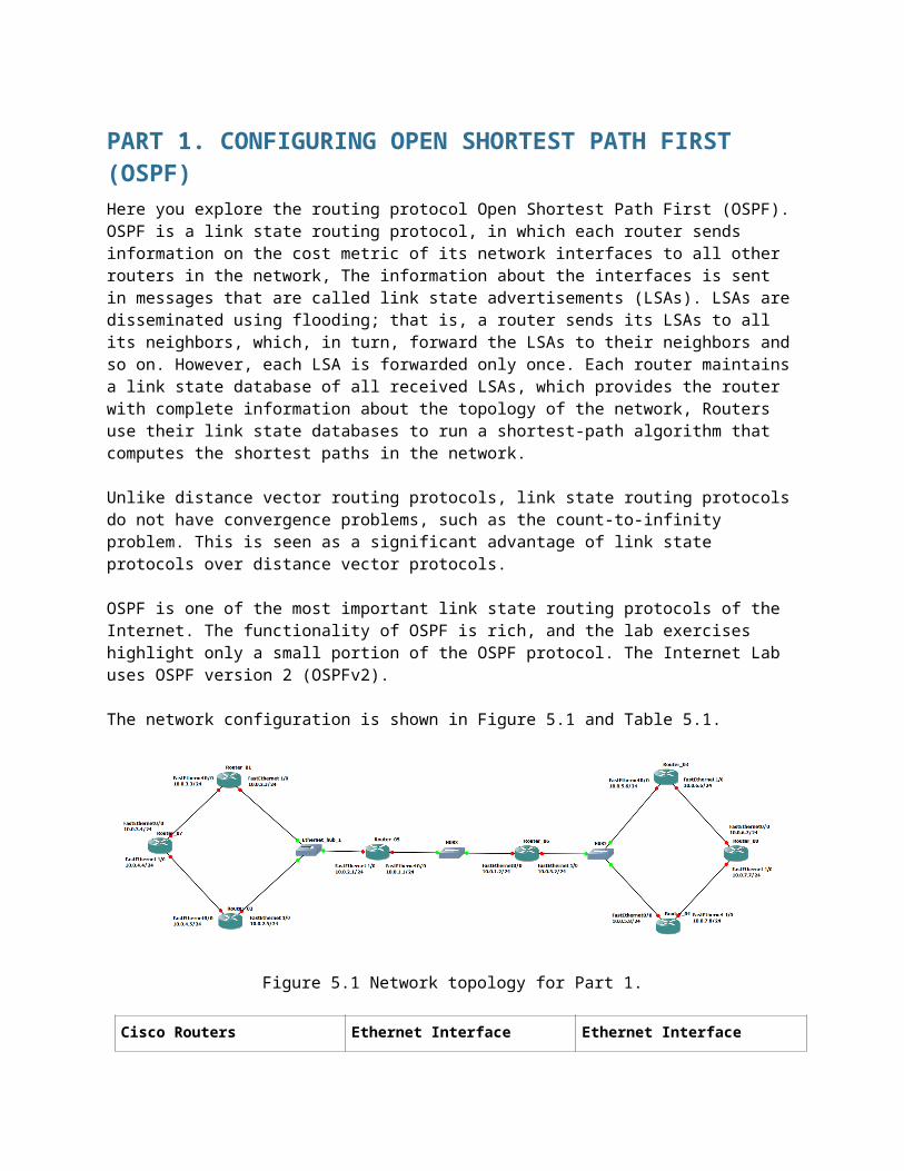
The network configuration is shown in Figure 5.1 and Table 5.1.
Figure 5.1 Network topology for Part 1.
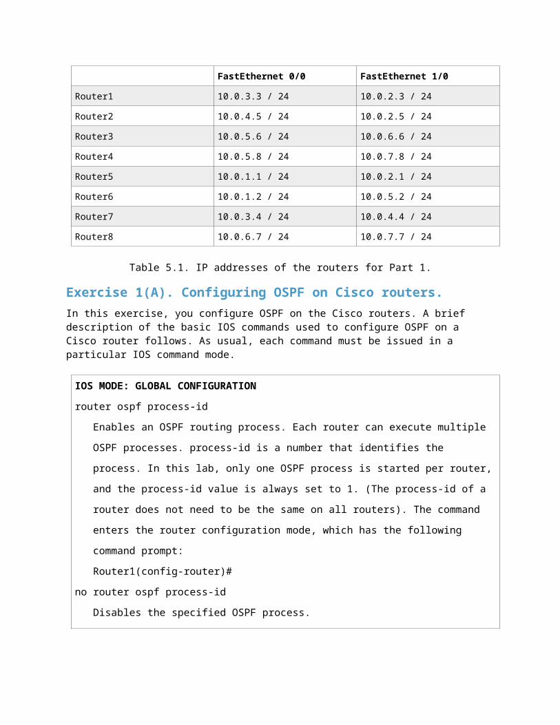
Cisco Routers Ethernet Interface FastEthernet 0/0
Ethernet Interface FastEthernet 1/0
Router1 10.0.3.3 / 24 10.0.2.3 / 24
Router2 10.0.4.5 / 24 10.0.2.5 / 24
Router3 10.0.5.6 / 24 10.0.6.6 / 24
Router4 10.0.5.8 / 24 10.0.7.8 / 24
Router5 10.0.1.1 / 24 10.0.2.1 / 24
Router6 10.0.1.2 / 24 10.0.5.2 / 24
Router7 10.0.3.4 / 24 10.0.4.4 / 24
Router8 10.0.6.7 / 24 10.0.7.7 / 24
Table 5.1. IP addresses of the routers for Part 1.
Exercise 1(A). Configuring OSPF on Cisco routers.In this exercise, you configure OSPF on the Cisco routers. A brief description of the basic IOS commands used to configure OSPF on a Cisco router follows. As usual, each command must be issued in a particular IOS command mode.
IOS MODE: GLOBAL CONFIGURATIONrouter ospf process-id
Enables an OSPF routing process. Each router can execute multiple OSPF processes.
process-id is a number that identifies the process. In this lab, only one OSPF process is
started per router, and the process-id value is always set to 1. (The process-id of a router
does not need to be the same on all routers). The command enters the router
configuration mode, which has the following command prompt:
Router1(config-router)#
no router ospf process-id
Disables the specified OSPF process.
IOS MODE: PREVILEGED EXECshow ip ospf
Displays general information about the OSPF configuration
show ip ospf database
Displays the link state database.
show ip ospf border-routers
Displays the Area Border Router (ABR) and Autonomous System Boundary Router
(ASBR).
clear ip ospf process-id process
Resets the specified OSPF process.
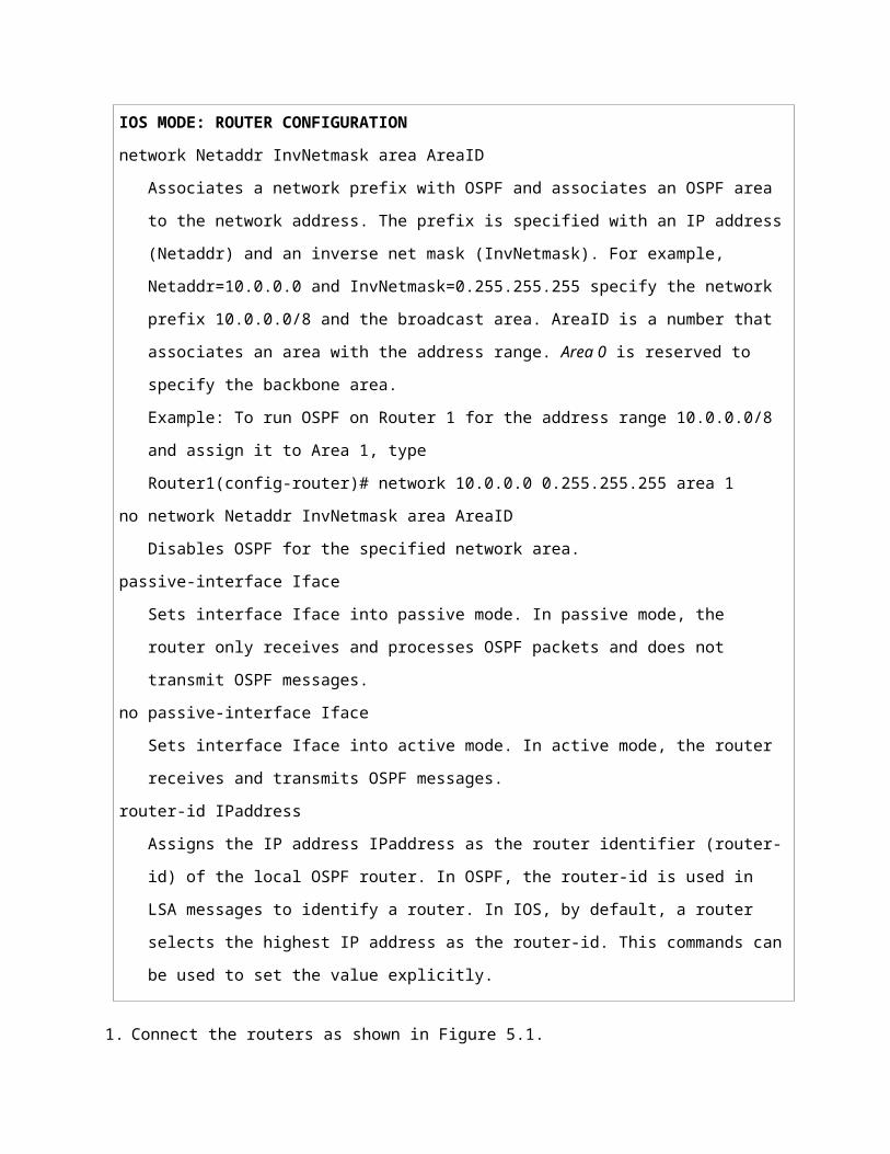
IOS MODE: ROUTER CONFIGURATIONnetwork Netaddr InvNetmask area AreaID
Associates a network prefix with OSPF and associates an OSPF area to the network
address. The prefix is specified with an IP address (Netaddr) and an inverse net mask
(InvNetmask). For example, Netaddr=10.0.0.0 and InvNetmask=0.255.255.255 specify the
network prefix 10.0.0.0/8 and the broadcast area. AreaID is a number that associates an
area with the address range. Area 0 is reserved to specify the backbone area.
Example: To run OSPF on Router 1 for the address range 10.0.0.0/8 and assign it to Area
1, type
Router1(config-router)# network 10.0.0.0 0.255.255.255 area 1
no network Netaddr InvNetmask area AreaID
Disables OSPF for the specified network area.
passive-interface Iface
Sets interface Iface into passive mode. In passive mode, the router only receives and
processes OSPF packets and does not transmit OSPF messages.
no passive-interface Iface
Sets interface Iface into active mode. In active mode, the router receives and transmits
OSPF messages.
router-id IPaddress
Assigns the IP address IPaddress as the router identifier (router-id) of the local OSPF
router. In OSPF, the router-id is used in LSA messages to identify a router. In IOS, by
default, a router selects the highest IP address as the router-id. This commands can be
used to set the value explicitly.
1. Connect the routers as shown in Figure 5.1.
2. Configure the Cisco routers to run OSPF. The following commands are used to configure Router1:
Router1> enableRouter1# configure terminalRouter1(config)# no ip routingRouter1(config)# ip routing Router1(config)# router ospf 1Router1(config-router)# network 10.0.0.0 0.255.255.255 area 1Router1(config-router)# interface FastEthernet0/0Router1(config-if)# no shutdownRouter1(config-if)# ip address 10.0.3.3 255.255.255.0Router1(config-router)# interface FastEthernet0/1

Router1(config-if)# no shutdownRouter1(config-if)# ip address 10.0.2.3 255.255.255.0Router1(config-if)# endRouter1# clear ip route *
Note:The command no ip routing is used to reset all previous configurations related to routing (static, RIP, OSPF, etc.) The command clear ip route * deletes all entries in the routing table. Make sure that all static routing entries are removed, since, by default, RIP and OSPF do not overwrite static routing entries in IOS.
The above commands enable OSPF for Area 1 and network 10.0.0.0/8, and configure the IP addresses of the routers. Since no router-id is specified in the configuration set up, the highest IP address of Router1, 10.0.3.3, will be used as the router-id. The router-id can be verified by issuing the command show ip OSPF.
3. Repeat the configuration on the other routers. Refer to Figure 5.1 for the connections and to Table 5.1 for the IP addresses.
4. From each router, issue a ping command to the IP address of interfaces FastEthernet0/0 and FastEthernet1/0 on all remote routers. For example, to issue a ping from Router7 to interface FastEthernet0/0 on Router6, type
Router7# ping 10.0.1.2
Your topology is correctly setup once you can successfully ping the connected interfaces of all routers.
A NOTE on "ping" command on routers:The default ping command in Cisco IOS issues only 5 ICMP Echo packets and the ping command doesn't have any arguments like -c in Linux on ipterm. However, here is a way to increase the number of packets (and change other parameters) when using ping on a router:
R1# ping
Protocol [ip]:
Target IP address: 10.0.1.10
Repeat count [5]: 1000
Datagram size [100]:
Timeout in seconds [2]:
Extended commands [n]:
Sweep range of sizes [n]:
Type escape sequence Ctrl + Shift + 6 to abort.
You can also use the repeat parameter as shown below to send, for example, 10 pings:
Router1# ping IP_addr repeat 10
5. When you are confident that all is set up correctly, continue to Ex 1(B).
Exercise 1(B). Observing convergence of OSPF.In comparison to distance vector based protocols, the link state routing protocol OSPF quickly adapts to changes in the network topology. In this exercise, you observe the interactions of OSPF after a change to the network topology.
1. On Router5, start to capture traffic with Wireshark on interface FastEthernet0/0. Set a filter to display only OSPF packets.
2. From Router7, run a trace command to Router8, FastEthernet1/0.
Router7# trace 10.0.7.7
3. Confirm from the output and Figure 5.1 whether the path from Router7 to Router8 (10.0.7.7) includes Router3 or Router4.
4. Issue a ping command with repeat 10000 from Router7 to Router8 (10.0.7.7). Immediately after issuing ping go to step 4. Dont wait for the pings to end.
Router7# ping 10.0.7.7 repeat 10000
5. If the path from Router7 to IP address 10.0.7.7 from Step 2 included Router3, then shutdown the FastEthernet1/0 interface of Router3. Otherwise, shutdown the FastEthernet1/0 interface of Router4. E.g. or Router3:
Router3(config)# interface FastEthernet1/0Router3(config-if)# shutdown
6. The ping should be unsuccessful (destination unreachable "U") for a while, and then start to work again when the routers have found a new route to IP address 10.0.7.7 (see step 7 below and do not terminate the ping still step 9).
7. Now OSPF updates the routing tables. Use the Wireshark window on Router5 to observe the transmitted OSPF messages:

• How quickly are OSPF messages sent after the cable is disconnected?• How many OSPF messages are sent?• Which type of OSPF packet is used for flooding link state information?• Describe the flooding of LSAs to all routers.• Which type of encapsulation is used for OSPF packets (TCP, UDP, or other)?• What is the destination address of OSPF packets?
8. Wait until the ping command is successful again, that is, ICMP Echo Reply messages arrive at Router7. This happens when the routing tables have been updated.
9. Stop/terminate the ping command and save the ping statics output.
From the number of lost/unsuccessful packets you can calculate the time it took OSPF to update the routing tables. (The ping command issues an ICMP Echo Request message approximately once every second.)
10. Issue another trace command from Router7 to Router8 IP address 10.0.7.7. Now the output should show the new route to Router8.
11. On each router show the link state database with the command “show ip OSPF database”.
Save the output of the link state databases on all the routers.
• Can you confirm that the link state databases are identical?
12. Stop Wireshark on Router5 and save the different types of OSPF packets captured by Wireshark. Save one copy of each type of OSPF packet that you observed.
Pick a single link state advertisement packet captured by Wireshark, and describe how to interpret the information contained in the link state advertisement.
13. Stop the routers.

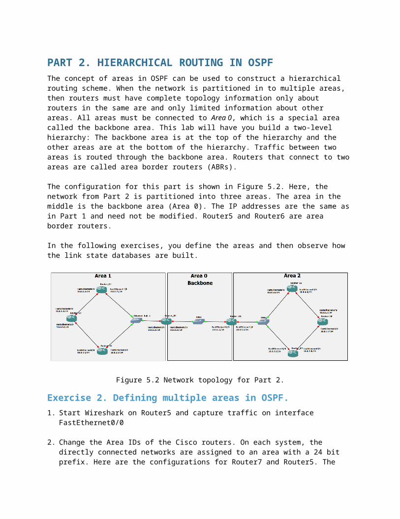
PART 2. HIERARCHICAL ROUTING IN OSPFThe concept of areas in OSPF can be used to construct a hierarchical routing scheme. When the network is partitioned in to multiple areas, then routers must have complete topology information only about routers in the same are and only limited information about other areas. All areas must be connected to Area 0, which is a special area called the backbone area. This lab will have you build a two-level hierarchy: The backbone area is at the top of the hierarchy and the other areas are at the bottom of the hierarchy. Traffic between two areas is routed through the backbone area. Routers that connect to two areas are called area border routers (ABRs).
The configuration for this part is shown in Figure 5.2. Here, the network from Part 2 is partitioned into three areas. The area in the middle is the backbone area (Area 0). The IP addresses are the same as in Part 1 and need not be modified. Router5 and Router6 are area border routers.
In the following exercises, you define the areas and then observe how the link state databases are built.
Figure 5.2 Network topology for Part 2.
Exercise 2. Defining multiple areas in OSPF.1. Start Wireshark on Router5 and capture traffic on interface FastEthernet0/0
2. Change the Area IDs of the Cisco routers. On each system, the directly connected networks are assigned to an area with a 24 bit prefix. Here are the configurations for Router7 and Router5. The other configurations are similar.
Router7, which belongs to only one area, is configured as follows:
Router7> enableRouter7# configure terminalRouter7(config)# no router ospf 1Router7(config)# router ospf 1Router7(config-router)# network 10.0.3.0 0.0.0.255 area 1Router7(config-router)# network 10.0.4.0 0.0.0.255 area 1Router7(config-router)# end

Router7# clear ip ospf 1 process
Router5 belongs to two areas and is configured as follows:
Router5> enableRouter5# configure terminalRouter5(config)# no router ospf 1Router5(config)# router ospf 1Router5(config-router)# network 10.0.2.0 0.0.0.255 area 1Router5(config-router)# network 10.0.1.0 0.0.0.255 area 0Router5(config-router)# endRouter5# clear ip ospf 1 process
3. Start Wireshark on Router5 and capture traffic on interface FastEthernet0/0.
4. Once the routing tables have converged, test the network configuration with the commands trace and ping on all routers. All routers should be able to communicate with one another.
5. Save the link state databases on all routers.
• Compare the link state databases to those saved in Part 1. What differences do you note?
• What information do routers in Area 1 have about Area 2? What information do they have about the backbone area (Area 0)?
• How much information do the routers in the backbone area (Area 0) have about the topology of Area 1 and Area 2?
• How do the routers in Area 1 know how to forward traffic to Area 2?
6. Display the area routers known to Router1 from Area 1, with the command
Router1# show ip ospf border-routers
Explain the output of the command show ip ospf border-routers.
7. From the Wireshark output of OSPF packet types, note the packet types that you did not see in Part 1.a)

PART 3. CONFIGURING THE BORDER GATEWAY PROTOCOL (BGP)The last part of this lab provides some exposure to the inter domain Border Gateway Protocol (BGP), which determines paths between autonomous systems on the Internet. The exercises in this lab cover only the basics of BGP. Essentially, you learn how to set up an autonomous system and observe BGP traffic between autonomous systems. BGP uses a path vector algorithm, where routers exchange full path information of a route. An important feature of BGP is that it can define routing policies, which can be used by a network to specify which type of traffic it is willing to process. The current version of BGP, which is also used in the following exercise, is BGP version 4 (BGP-4)
The network configuration for this part is shown in Figure 5.3, and the IP configuration information is given in table 5.3. the network has three autonomous systems with AS numbers 100, 200 and 300. One PC, PC4, is used to capture the BGP packets transmitted between the ASs.
Figure 5.3 Network topology for Part 3.
PC Ethernet Interface eth0 Default Gateway
PC1 10.0.1.10 / 24 10.0.1.1
PC2 10.0.2.10 / 24 10.0.2.2
PC3 10.0.3.10 / 24 10.0.3.3
PC4 10.0.4.10 / 24
Cisco Routers Ethernet Interface FastEthernet 0/0
Ethernet Interface FastEthernet 0/1
Router1 10.0.1.1 / 24 10.0.4.1 / 24
Router2 10.0.2.2 / 24 10.0.4.2 / 24
Router3 10.0.3.3 / 24 10.0.4.3 / 24
Table 5.3 IP addresses of the routers and PCs for Part 3.
Exercise 3(A). Basic BGP configuration.In this exercise you will configure the Cisco routers as BGP routers and assign routers to autonomous systems. The configuration is completed when you can issue ping commands between any two PCs. Below we summarize the Cisco IOS commands that are used to enable BGP.
IOS MODE: GLOBAL CONFIGURATIONrouter bgp ASnumber
Enables the BGP routing protocol and sets the autonomous system number to ASnumber.
The command enters the router configuration mode with the following prompt:
Router1(config-router)#
no router bgp ASnumber
Disables the BGP routing process.
IOS MODE: PREVILEGED EXECshow ip bgp
Displays the BGP routing table.
show ip bgp neighbors
Displays the neighbors, also called peers, of this BGP router.
show ip bgp paths
Displays the BGP path information in the local database.
clear ip bgp *
Deletes BGP routing information
IOS MODE: ROUTER CONFIGURATIONnetwork Netaddr
network Netaddr mask netmask

Specifies a network address that will be advertised by the local BGP process. A network
mask maybe added to denote the length of the network prefix.
neighbor IPaddress remote-as ASnumber
Adds a neighbor to the BGP neighbor table. IPaddress is the IP address and ASnumber is
the AS number of the neighbor.
timers bgp keepalive holdtime
Sets the values of the keep alive and hold time timers of the BGP process. BGP routers
exchange periodic messages to confirm that the connection between the routers is
maintained. The interval between these messages is keep alive seconds (default: 60
seconds). The number of seconds that a BGP router waits for any BGP message before it
decides that a connection is down is specified by the hold time (default: 180 seconds).
1. Disable all RIP or OSPF processes that are running on the Cisco routers. Use the following commands:
Router1# no router ospf 1Router1# no router rip
2. Assign the IP addresses to Ethernet interface eth0 of each PC as indicated in Table 5.3
3. Add a default gateway to PC1, PC2, and PC3 as shown in Table 5.3.
PC1% route add default gw 10.0.1.1/24PC2% route add default gw 10.0.2.2/24PC3% route add default gw 10.0.3.3/24
4. Start Wireshark on PC4 and set a display filter to capture only BGP packets.
5. Configure the Cisco routers to run BGP with the autonomous system numbers shown in Figure 5.3. The routers must know the AS number of their neighbors. Following is the configuration for Router2. Router2 is in AS 200 and neighbors are AS 100 and AS 300.
Router2> enableRouter2# configure terminalRouter2(config)# no ip routingRouter2(config)# ip routingRouter2(config)# interface FastEthernet0/0Router2(config-if)# no shutdownRouter2(config-if)# ip address 10.2.2 255.255.255.0Router2(config-if)# interface FastEthernet1/0Router2(config-if)# no shutdownRouter2(config-if)# ip address 10.0.4.2 255.255.255.0Router2(config-if)# router bgp 200Router2(config-router)# neighbor 10.0.4.1 remote-as 100

Router2(config-router)# neighbor 10.0.4.3 remote-as 300Router2(config-router)# network 10.0.2.0 mask 255.255.255.0Router2(config-router)# endRouter2# clear ip bgp *
6. On PC1, issue a ping command to PC3. The command succeeds when BGP has converged.
PC1% ping -c 5 PC3
7. Once the routing tables have converged, you should see all the other AS entries in the BGP routing table. On each Cisco router, save the output of the following commands (you will need this output to compare to results from Ex 6(B):
Router1# show ip routeRouter1# show ip bgpRouter1# show ip bgp paths
8. Stop the Wireshark traffic capture on PC4 and save the BGP packets captured by Wireshark.
• Describe the different types of BGP messages that you observe in the Wireshark window on PC4.
• Notice that BGP transmits messages over TCP connections. What is a reason that BGP uses TCP to transmit its messages?
• What is the IP address of the next-hop attribute for AS 100 on Router2?• What are the BGP peers in this topology?• Which BGP message(s) contain(s) the AS-PATH information? Use a BGP message to
illustrate your answer.• Use the saved output to provide a brief explanation of how the routers find the proper
path between the autonomous systems.
Exercise 3(B). BGP convergenceIn this exercise you will disconnect one of the links between two BGP peers and observe how the BGP protocol reconfigures the paths.
1. On PC4 start Wireshark and set a display filter for BGP. Observe the flow of BGP packets between the autonomous systems.
2. On all routers, change the keepalive timer to 10 seconds and the holdtime timer to 30 seconds. This speeds up the convergence time by a factor of 6 as compared to the default values. The following are the commands for Router2:
Router2# configure terminalRouter2(config)# router bgp 200Router2(config-router)# timers bgp 10 30Router2(config-router)# endRouter2# clear ip bgp *
3. Shutdown the cable of interface FastEthernet1/0 on Router1.

Router1(config)# interface FastEthernet1/0Router1(config-if)# shutdown
• From the Wireshark output, observe how the BGP routers learn that a link is down.
4. Wait until BGP converges. Save the routing tables on Router2 and Router3.
What changes do you see?
5. Use the command show ip BGP summary on Router2 and Router3 to obtain the neighbor information.
Compare to previous result from Ex 3(A). What changes do you see?
6. Save the routing tables on Router2 and Router3.
What changes do you see from results in Ex 3(A)?
7. Stop the Wireshark traffic captured on PC4 and save the Wireshark BGP packets.
Which BGP messages indicate that there is a link problem? Use a BGP message to answer the question. (Hint: Look for the BGP update messages and check the "Withdrawn routes." )