setup and verification of a multi-gnss over-the-air wave
TRANSCRIPT

Setup and Verification of a Multi-GNSSOver-The-Air Wave Field Synthesis Testbed
Alexander Rugamer∗, Christopher Schirmer§, Mario Lorenz§, Simon Taschke∗,Marcus Grossmann‡, Markus Landmann‡, Wolfgang Felber∗
∗Fraunhofer IIS, Nuremberg, Germany§Technische Universitat Ilmenau, Germany
‡Fraunhofer IIS, Ilmenau, Germany
Abstract—In this paper, we describe the principle, hard-ware/software setup, calibration and verification measurementresults of a wave field synthesis (WFS) over-the-air (OTA) testbedfor global navigation satellite systems (GNSS). It representsa new approach that, in contrast to conventionally conductedand open-field tests, realistically emulates real world scenariosunder controllable and repeatable conditions. This enables therealistic comparison of receivers and algorithms especially formulti/beamforming antenna receivers as well as for receiverswith integrated antennas. Having outlined the architecture andhardware setup of the WFS OTA testbed together with the GNSSconstellation simulator, we describe the current 2D setup and theupcoming 3D installation. Then we discuss and present resultsof two different ways of calibration and validation carried outin the 2D setup: firstly, using an electromagnetic field probe,and secondly, using a commercial geodetic GNSS antenna withreference receiver in a 2.5D emulation.
Index Terms—Satellite Navigation Systems, Global PositioningSystem, Over-the-Air Testing, Wave Field Synthesis
I. INTRODUCTION
In contrast to conventionally conducted and open field
device testing, the over-the-air (OTA) test represents a novel
approach that allows, by the use of wave-field synthesis
(WFS), the realistic emulation of real world scenarios under
controllable and repeatable conditions inside an anechoic
chamber, see Figure 1. The benefits of such a controlled test
environment are the realistic performance assessment and the
product evaluation of different wireless technologies, without
the need for special frequency licensing or other interference
restraints required for open field tests [1], [2].
Recently, interference mitigation techniques utilizing an-
tenna arrays have attracted a lot of interest in global nav-
igation satellite system (GNSS) applications. The main ad-
vantage of directional steerable antennas in GNSS systems
is the suppression of jammers and spoofers as well as the
higher reception signal quality in multipath fading channel
environments. However, this advantage comes at the cost
of increased device testing effort. In this regard, traditional
device test measurement procedures such as the conducted
measurement test are not able to cover the spatial dimension
of the propagation channel as the air interface is bridged by
cables towards the device tester. To cope with that issue,
the two-stage conducted testing approach that includes the
effects of the propagation channel and the antenna radiation
pattern was developed, see [3]. However, a drawback of this
Fig. 1. Principle of Over-the-air testing inside an anechoic chamber
procedure is the inaccessibility of small and compact antennas
in integrated devices, as it is not always possible to access the
antenna ports without destroying the device under test (DUT),
or at least significantly altering its electromagnetic properties.
In comparison to the well-known methods for device testing,
the wave-field synthesis (WFS) Over-The-Air (OTA) approach
provides the opportunity to test a device in a holistic way [4].
The DUT is placed in an anechoic chamber surrounded by an
antenna ring or (hemi)-sphere to recreate the electromagnetic
environment virtually in the chamber, as depicted in Figure
1. The advantages of the OTA method are the following:
The device can be tested without unmounting the device’s
antenna. Multiple devices of the same or of different types can
be tested using exactly the same measurement environment.
No electromagnetic disturbance from the outside to the test
environment and vice versa has to be taken into account.
Therefore, even classified signals, e. g., Galileo PRS or GPS
PPS can be safely tested within the protected chamber as
well as jamming and spoofing which are not allowed to
be carried out in the free field without permission. Finally,
the propagation channel conditions (e. g. multipath) of GNSS
signals but also of jammers and spoofers can be emulated in
great detail.
In 2013, the Facility for Over-the-air Research and TEsting
(FORTE) was put into operation by Fraunhofer IIS [5]. It
hosts two basic research platforms, a testbed for Satellite
Communication on the Move (SOTM) terminals and an envi-
ronment for Over-the-Air (OTA) testing of GNSS applications.
Besides GNSS testing, the testbed also enables realistic radio
channel emulation for LTE, LTE-A and cognitive radio, sensor
978-1-5090-2042-3/16/$31.00 © 2016 IEEE 863

networks, car-to-car and car-to-infrastructure communications.
This paper is organized as follows: Section II summarizes
the identified applications for WFS OTA GNSS testing. Sec-
tion III briefly summarizes the principle and setup of the
FORTE WFS OTA system with its capabilities and limitations.
The GNSS simulator that is connected to the WFS OTA is
outlined, followed by the description of the antenna setup
with the calibration procedure. Section IV describes the mea-
surement setup and verification methodology of the current
WFS OTA GNSS setup with their verification measurement
results. Section V discusses the measurement results and
performance comparisons to conventionally conducted GNSS
RF constellation simulator tests. Finally, Section VI concludes
the paper.
II. APPLICATIONS FOR WFS OTA TESTING
Today’s mass-market GNSS receivers, e.g. contained in
handheld mobile phones, are tested and verified for position
accuracy, acquisition sensitivity, time-to-first-fix and other
benchmarks, but not for their robustness against intentional
interferences. Testing, qualification and certification—at least
for safety-critical receivers—are regarded as a must and nec-
essary to guarantee a certain minimum standard.
The WFS OTA approach provides a novel testing method
for interference robustness assessments of GNSS receivers
equipped with integrated antennas, or external ones, but es-
pecially with phased array antennas. The identified use cases
for the WFS OTA testing range from GNSS device testing
with classical open service GPS/Galileo signals to classified
signals (e.g. GPS PPS or Galileo PRS) and different multipath
propagation conditions that include jammers and spoofers. In
the following subsections, the identified use cases for WFS
OTA testing are described in detail.
A. Use Case 1: GNSS Receivers with Integrated Antennas
Smartphones, portable car navigation systems as well as
highly integrated navigation devices (e.g. GPS Watch, hand-
held navigation receivers for outdoor activities, etc.) have
an integrated GNSS antenna. Neither can an external GNSS
antenna can connected to these devices nor can the internal
antenna be separately measured and characterized. However,
the antenna is a critical element for the overall receiver
functionality, as the antenna design has a strong influence on
the receiver sensitivity as well as the receiver’s susceptibility
in terms of multipath and interference suppression. A conven-
tional cable-connected simulator cannot accurately test such
an integrated system. With the aid of the WFS OTA testing
approach, realistic end-to-end tests for GNSS DUT receivers
equipped with integrated antennas can be performed ”as it is”
in a realistic and reproducible testing environment.
B. Use Case 2: GNSS Receivers with Array Antennas
In contrast to legacy mobile devices that encounter a harsh
mobile channel environment, GNSS receivers are faced with
intentional interferences. This is becoming a critical issue,
as more and more GNSS receivers are used for security
related applications. These are the traditional military GNSS
services, flight approach and Ground Based Augmentation
Systems (GBASs). But besides that, upcoming consumer ap-
plications may incorporate Advanced Driving Assistance Solu-
tions (ADAS) up to automatic driving or guidance for vision
impaired people. Moreover, the GNSS time is widely used
for synchronization of distributed systems, e.g., mobile device
base station networks, phase-synchronous current injection of
decentralized power plants, and many more.
To provide protection against interferences, GNSS receivers
equipped with phased array antennas can be a powerful
solution. For instance, a very effective interference mitigation
method is utilizing a Controlled Reception Pattern Antenna
(CRPA). This type of phased array antenna places nulls in
the direction of the interferer to protect the receiver from
impairments. Commercial products are already available on
the market, like the 7-element CRPA named GAJT from
Novatel/Qinetiq [6].
A more sophisticated solution provides a beam-steering
antenna, e.g. developed by the German Aerospace Center
(DLR) within the BaSE project [7]. In this approach, several
beams are steered in each direction of the satellite signals to
be received. Due to the increased gain in a specific direc-
tion, possible interferences coming from other directions are
attenuated. Moreover, such beam-steering antennas provide the
possibility to detect spoofers: Typically, a spoofer broadcasts
all signals from a single point in space, whereas the desired
GNSS information is inherently linked to the spatial diversity
of the satellite signals. By using a phased array antenna, the
Direction of Arrival (DoA) can be estimated at the receiver
side, independently from the transmitted GNSS message. This
cross check enables effective spoofing detection [8].
To test GNSS receivers equipped with an array antenna,
a simulator setup taking into account the spatial component
of the channel must be used. This cannot be done with a
conventional single RF-output GNSS constellation simulator,
but with the WFS OTA testing approach as installed at FORTE.
C. Use Case 3: GNSS Receivers in High Dynamic Environ-ments
The WFS OTA testbed emulates the physical direction of
the received GNSS signals, multipath channel components
and/or jammers by wave field synthesis. This approach allows
for a continuous angular motion of the transmitter (satellite,
jammer, and spoofer) in space. Moreover, huge dynamic range
changes in terms of Doppler shift can be emulated (e.g.
acceleration of a rocket or a plane) via WFS without the need
of physically moving the DUT. If scenario coherent inertial
data is required, the GSS9000 can be coupled with Spirent’s
SimInertial simulation system.
D. Use Case 4: GNSS Receivers with Classified Signalsand/or Jammers
Conventional free-field test ranges like the GATE testbeds in
Germany are not suited to test the receiver’s robustness against
interference. The operation of a powerful jammer or spoofer
864

in an open field would also affect surrounding receivers and
therefore requires a special frequency license to be legally au-
thorized. Moreover, the testing, optimization, and verification
of not yet certified receiver designs that incorporate classified
signals (e.g. Galileo PRS or the GPS PPS) are generally not
allowed in conventional free field testbeds, since stringent anti-
tamper requirements and limitation of radiation have to be
guaranteed.
Thanks to the anechoic chamber in which the WFS OTA
testing is installed and the facility security clearances of the
installation site, testing with both the military GPS signals as
well as with the Galileo Public Regulated Service (PRS) sig-
nals are possible in the installation. Even high-power jammers
can be used within the OTA’s anechoic chamber without any
harm to the outside environment.
III. OVER-THE-AIR TESTING FOR GNSS SYSTEMS
A. FORTE WFS OTA Hardware Setup
A WFS OTA testbed for emulating complex electromagnetic
wave fields with signal bandwidths up to 80 MHz in the
frequency range of 350 MHz to 3 GHz is operated at Fraun-
hofer IIS FORTE. The wave field impinging at the device-
under-test (DUT) is generated as a coherent superposition
of pre-defined, discrete plane wave components with certain
directions, delays, amplitudes and phases that are radiated by
several OTA illumination antennas. That way, an arbitrary
multipath propagation channel and interference environment
can be emulated at the DUT (e. g. a GNSS receiver).
Specifically, as shown in Fig. 2 and Fig. 3, the WFS
OTA testbed consists of a GNSS radio frequency constellation
simulator (RFCS) (Spirent GSS9000 TS788) as signal source,
an OTA channel emulator, and 32 OTA illumination antennas
surrounding the DUT. Up to 12 signals can be fed into
the system. These signals can be individual GNSS satellite
signals from the Spirent GSS9000 TS788 or radio frequency
(RF) signals, e.g. of interferers. While the Spirent GSS9000
TS788 signals only need to be adapted in the format, the
RF input signals are converted to digital base-band (DBB)
signals by analog-to-digital down-converter (ADD) units. The
DBB signals are then distributed to each of 16 FPGA Digital
Signal Processors (FDSP). A single FDSP convolves all 12
input signals with the coefficients of the propagation channel
model for the target scenario. The propagation channel model
includes the complex WFS weights for each individual channel
tap delay to control the direction of the multipath components.
Note that the signal convolution can be accomplished either
in the time or frequency domain. When performing the signal
convolution in the frequency domain, the OTA testbed supports
the emulation of channel impulse responses with an almost un-
limited number of propagation paths. This means the emulated
wave field is not restricted to a certain number of channel delay
taps. Finally, the output signals of each FDSP are converted
to the analog domain and mixed up to the operating frequency
by the digital-to-analog up-converters (DAUs). Each DAU
has two RF outputs, which add up, in total, to 32 analog
output channels. Thus, each of the 32 output signals is a
OTAWFS
Signal distribution
(up to 12 individual sources @ 80MHz)
FDSP S1000FDSP S1000FDSP S1000FDSP S1000FDSP S1000FDSP S1000FDSP S1000FDSP S1000FDSP S1000FDSP S1000FDSP S1000FDSP S1000
6x10GBitOptical fibre
DUT trajectory(position, speed,
orientation)GNSS Settings (System, Time,
GNSS Parameters)
FDSP S1000FDSP S1000FDSP S1000FDSP S1000
1x10GBitOptical fibre
32x RF output
GSS9000
C50rSimGEN
Signal generator
Propagation channel,Sattelite Az/El, Signal Level
To OTAemulationantennas
Digital base bandsatellite signals
Fig. 2. FORTE 3D-WFS OTA schematic for GNSS testing
superposition of the 12 convolved input DBB signals. The
output signals are fed into the 32 OTA emulation antennas.
The antennas reproduce dual-polarization with perpendicularly
arranged Vivaldi-horns to be able to emulate linear as well as
left/right hand circular polarization (L/RHCP). The emulation
antennas are placed in either a 2-dimensional or a spherical
setup around the DUT. The maximum RF output power per
channel is +10 dBm, resulting in a maximum of ≈-45 dBm at
the DUTs position.
When using WFS for OTA testing, the maximum DUT
size is restricted by the number of phase coherent hardware
channels, the operating frequency, and the OTA emulation
antenna constellation. Following the spatial sampling theorem
for a 3-dimensional arrangement of OTA emulation antennas
D <√M · λ/(2√π), a maximum electrical size of the DUT
with D = 0.21m for an arrangement of M = 16 dual-
polarized OTA emulation antennas can be achieved. Using
M = 32 OTA emulation antennas, the possible electrical DUT
diameter increases to D = 0.30m [9]. In a 2-dimensional
setup, we can achieve a maximum electrical DUT diameter of
0.48 m/0.73 m/0.97 m using the the spatial sampling equation
for the 2D case D = λ/2 ·M/π and M = 16/24/32 emulation
antennas [10], [11].
B. GNSS Emulator for WFS OTA Setup
A ”Tailored Solution” (TS) based on the new GSS9000
series of Spirent’s high-end GNSS signal emulator was cus-
tomized for Fraunhofer IIS. The so called GSS9000 TS788
was modified with specific digital I/Q output channels instead
of the conventional composite analog RF output port. Each
satellite’s individual raw baseband signal (including navigation
messages, PRN-codes, Doppler-offsets, and relative power
adjustment between the signals but no noise) is digitally
converted to the format used by the OTA channel emulator
and fed into the signal distribution unit, as depicted in Figure
2. The information about the simulated satellites’ positions and
their respective power levels are streamed from the GSS9000
TS788 control PC running Spirent’s SimGEN software via
865
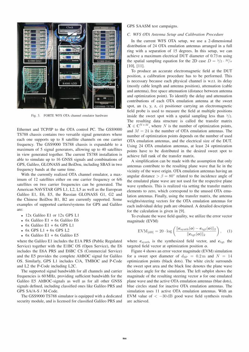
S1000 DAU
FDSP
Clock
R4000 ADD
S1000 DAU
FDSP
SpirentGSS9000 TS788
Fig. 3. FORTE WFS OTA channel emulator hardware
Ethernet and TCP/IP to the OTA control PC. The GSS9000
TS788 chassis contains two versatile signal generators where
each one supports up to 8 satellite channels on one carrier
frequency. The GSS9000 TS788 chassis is expandable to a
maximum of 5 signal generators, allowing up to 40 satellites
in view generated together. The current TS788 installation is
able to simulate up to 16 GNSS signals and combinations of
GPS, Galileo, GLONASS and BeiDou, including SBAS in two
frequency bands at the same time.
With the currently realized OTA channel emulator, a max-
imum of 12 satellites either on one carrier frequency or 6/6
satellites on two carrier frequencies can be generated. The
American NAVSTAR GPS L1, L2, L5 as well as the European
Galileo E1, E6, E5, the Russian GLONASS G1, G2 and
the Chinese BeiDou B1, B2 are currently supported. Some
examples of supported carriers/systems for GPS and Galileo
are:
• 12x Galileo E1 or 12x GPS L1
• 6x Galileo E1 + 6x Galileo E6
• 6x Galileo E1 + 6x GPS L1
• 6x GPS L1 + 6x GPS L2
• 6x Galileo E1 + 6x Galileo E5
where the Galileo E1 includes the E1A PRS (Public Regulated
Service) together with the E1BC OS (Open Service), the E6
includes the E6A PRS and E6BC CS (Commercial Service)
and the E5 provides the complete AltBOC signal for Galileo
OS. Similarly, GPS L1 includes C/A, TMBOC and P-Code
and L2 the P-Code including L2C.
The supported signal bandwidth for all channels and carrier
frequencies is 60 MHz, providing sufficient bandwidth for the
Galileo E5 AltBOC-signals as well as for all other GNSS
signals defined, including classified ones like Galileo PRS and
GPS SA/A-S / M-Code.
The GSS9000 TS788 simulator is equipped with a dedicated
security module, and is licensed for classified Galileo PRS and
GPS SAASM test campaigns.
C. WFS OTA Antenna Setup and Calibration Procedure
In the current WFS OTA setup, we use a 2-dimensional
distribution of 24 OTA emulation antennas arranged in a full
ring with a separation of 15 degrees. In this setup, we can
achieve a maximum electrical DUT diameter of 0.73 m using
the spatial sampling equation for the 2D case D = λ/2 · M/π[10], [11].
To produce an accurate electromagnetic field at the DUT
position, a calibration procedure has to be performed. This
is necessary because each physical channel is w.r.t. its delay
(mostly cable length and antenna position), attenuation (cable
and antenna), free space attenuation (distance between antenna
and optimization point). To identify the delay and attenuation
contributions of each OTA emulation antenna at the sweet
spot, an (x, y, z, φ) positioner carrying an electromagnetic
field probe is used to measure the field at multiple positions
inside the sweet spot with a spatial sampling less than λ/2.The resulting data structure is called the transfer matrix
X ∈ CN×M , where N is the number of optimization points,
and M = 24 is the number of OTA emulation antennas. The
number of optimization points depends on the number of used
OTA emulation antennas, and the electrical size of the DUT.
Using 24 OTA emulation antennas, at least 24 optimization
points have to be distributed in the desired sweet spot to
achieve full rank of the transfer matrix.
A simplification can be made with the assumption that only
antennas contribute to the resulting plane wave that lie in the
vicinity of the wave origin. OTA emulation antennas having an
angular distance > β = 80◦ related to the incidence angle of
the emulated plane wave are not used for the respective plane
wave synthesis. This is realized via setting the transfer matrix
elements to zero, which correspond to the unused OTA emu-
lation antennas. Finally, using the transfer matrix, the antenna
weights/steering vectors for the OTA emulation antennas for
each individual delay path are obtained. A detailed description
for the calculation is given in [9].
To evaluate the wave field quality, we utilize the error vector
magnitude (EVM)
EVM[dB] = 20 · log(‖esynth(o)− etgt(o)‖2
‖etgt(o)‖2
), (1)
where esynth is the synthesized field vector, and etgt the
targeted field vector at optimization position o.
Figure 4 shows an error vector magnitude (EVM) simulation
for a sweet spot diameter of dSP = 0.2m and N = 14optimization points (black dots). The white circle surrounds
the sweet spot area and the black line denotes the plane wave
incidence angle for the simulation. The left subplot shows the
magnitude of the resulting steering vector s for one emulated
plane wave and the active OTA emulation antennas (blue dots),
blue circles stand for inactive OTA emulation antennas. The
simulation uses 11 active OTA emulation antennas. With an
EVM value of < −30 dB good wave field synthesis results
are achieved.
866

Fig. 4. EVM distribution inside sweet spot (white circle) having used 14optimization points (black dots), dSP = 0.2m. The red lines with accordingvalues depict the power contribution of the active OTA emulation antennas.The wave origin is depicted by the black line.
Fig. 5. EVM distribution inside sweet spot (white circle) having used 27optimization points (black dots), dSP = 0.3m. The red lines with accordingvalues depict the power contribution of the active OTA emulation antennas.The wave origin is depicted by the black line.
The initial measurements were conducted with the dSP =0.2m configuration, as the geometrical size of the GNSS
DUT (a geodetic multi-GNSS antenna) is in the same region.
However, the first measurement results yielded a positioning
bias of ≈ 0.5m (plot not shown here). The wave-field
synthesis measurements were repeated using a larger sweet
spot diameter of dSP = 0.3m and also having 27, instead of 14
optimization points, cf. Figure 5. The EVM distribution now
shows better values, especially around the sweet spot borders.
This is important because the electrical size of an antenna is
usually greater than the geometrical one. This measurement
configuration was used in the following for comparing the
WFS OTA generated satellite signals with the conducted and
the single-antenna ones.
IV. VERIFICATION MEASUREMENTS
This chapter presents the methodology and verification re-
sults of the WFS OTA testbed (including the Spirent GSS9000
TS788) compared to conventional Spirent GSS9000 conducted
measurements. The objective is to verify the simulations by
Fig. 6. Default race track scenario of Sprient’s SimGen
comparing the positioning accuracy obtained by the WFS OTA
method with the GSS9000 RFCS conducted measurements,
which are generally accepted as accurate.
For a realistic end-to-end check, a professional geodetic
GNSS antenna (NavXperience 3G+C multi-GNSS antenna)
developed by Fraunhofer IIS [12], together with the GNSS
reference receiver Septentrio PolarRx4 were used. Two test
scenarios were selected for the verification of the measure-
ments.
• Static scenario: GPS L1 C/A only; Position lat/long
0◦/0◦; no atmospheric effects; default settings of Spirent’s
SimGen
• Race track scenario: GPS L1 C/A only; Position track
around lat/long 0◦/0◦; no atmospheric effects; default
settings of Spirent’s SimGen, see Figure 6
Note that other GNSS signals or combinations can be
simulated as well. As explained in Section III-B, the WFS
OTA emulation does not depend on the chosen GNSS signals.
Therefore, a GPS only scenario was selected without loss of
generality.
The GNSS receiver was set to its default settings, except the
intentional disabling of tropospheric and ionospheric correc-
tions as no atmosphere was simulated. Moreover, the receiver
was restarted (”soft reset” with deletion of every receiver inter-
nal setting except its configuration) before each measurement
run. Each scenario was simulated for approx. 5 minutes. The
receiver logged every measurement in the Septentrio Binary
Format (SBF), which was then further processed in Matlab.
As depicted in Figure 8, the reception pattern of the geodetic
867

Fig. 7. WFS OTA setup with geodetic antenna
-80 -60 -40 -20 0 20 40 60 80
Coelevation [deg]
-14
-12
-10
-8
-6
-4
-2
0
Dir
ectiv
ity [
dB]
3G+C Antenna Pattern variation
Fig. 8. Measured azimuth vs. elevation radiation patterns of the 3G+Cantenna
GNSS antenna is nearly identical in the azimuth plane, each
black line denotes a pattern slice, step size 10◦ azimuth,
but it provides a significant attenuation (due to multipath
suppression) at elevation angles below 15◦. Thus, a 2.5D
simulation of a single GNSS antenna/receiver setup can be
done in the 2D OTA ring by tilting the GNSS antenna by 90◦
relative to the OTA ring, as depicted in Figure 7. Then, all
GNSS satellites’ azimuth angles can be projected onto the 2D
ring, emulating the GNSS satellites’ elevation.
The satellites’ elevation is emulated via the FORTE WFS
OTA channel emulator. With this setup, a quasi 3D or 2.5D
WFS OTA GNSS emulation can be performed. The GNSS
signal is emulated and the reference receiver’s output is used
to assess the GNSS position.
To verify the measurements, six different setups were used
for the emulation of the scenarios ”static” and ”race track”.
Fig. 9. Measurement setup
The positioning result plots shown in Fig. 11 and Fig. 12
provide the obtained mean with its 1-σ and 2-σ 2-D horizontal
error with respect to the emulated lat/long 0◦/0◦ position. For
the dynamic scenario ”race track”, the reference was sub-
tracted from the obtained position to show the 2-D horizontal
error only.
In the following, we describe the six different measurement
setups, which are depicted in Figure 9.
A. TS788 Conducted Test
As explained in the OTA GNSS emulator setup, the dig-
ital outputs of each simulated satellite are passed from the
GSS9000 TS788 RFCS to the FDSPs. Here, the signal convo-
lution takes place. In this first test, all incoming RFCS signals
are digitally combined into a single digital composite signal,
meaning that each satellite signal’s steering vector is constant.
This digital signal is then routed to one S1000 DAU’s analog
output and RF up-converters. Instead of using OTA emulation
antennas for transmission, a direct cable connection to the
GNSS reference receiver was used.
This test checks if all digital signals are handled correctly
and are free of any (relative) latencies introduced by the WFS
OTA testbed, which would directly lead to systematic position
errors.
868

The positioning error for the two simulated scenarios in this
configuration are depicted in Figures 11(a) and 12(a).
B. TS788 Single Emulation Antenna OTA
In this test, the same configuration as in the previously
conducted one was used, but now the composite signal was
transmitted ”over-the-air” to the DUT using one single OTA
emulation antenna directly facing the GNSS antenna, see
Figure 7.
The results should be the same as for the conducted test
before, if the influence of the transmission antenna and the
anechoic chamber are negligible.
The positioning errors for the two simulated scenarios in
this configuration are depicted in Figures 11(b) and 12(b).
C. TS788 Single-Directional WFS OTA
In this configuration, the WFS steering vector is calculated
in a way that all GNSS signals are targeting the reception
antenna from boresight single direction—thus from 90◦ ele-
vation, see Figure 4.
In contrast to the previous composite single transmitter
antenna test, several OTA emulation antennas are transmitting
signals with the objective to form a plain wavefront from
entering the reception antenna frontally. This is the first test
of WFS, forming a sweet spot in the vicinity of the GNSS
antenna. The results should be comparable to the single
transmitter antenna test before. The positioning errors are
shown in Figures 11(c) and 12(c).
D. GSS9000 - Conducted without Antenna Pattern Simulation
To verify the results of the TS788/WFS OTA, the same three
verification measurements were carried out in a conducted
way with the with a conventional RF-output Spirent GSS9000
simulator. The exact same scenario as for the TS788 WFS
OTA configuration was used, however, the C/N0 settings had
to be calibrated first, as discussed in the Subsection IV-G. No
effects of the reception antenna were simulated at first, to have
a fair comparison to the single direction tests. The results are
shown in Figures 11(d) and 12(d).
E. TS788 Multi-Directional WFS OTA
In this configuration, the elevation of each emulated satellite
signal was projected on the azimuth of the 2D-OTA constella-
tion. This was done by using wave field synthesis, resulting in
plane wave fronts from different angles of arrival within the
emulation’s sweet spot, where the antenna was located.
By simulating the different elevations, the antenna’s re-
ception pattern leads to significant attenuation e.g. for low
elevation signals. This is the reason why the position is much
less accurate as for all the measurements before, as shown in
Figures 11(e) and 12(e).
F. GSS9000 - Conducted with Antenna Pattern Simulation
In the second run of the GSS9000 reference simulations, the
GNSS reference reception antenna used was modeled in its
level and phase patterns (see Figure 8) over elevation/azimuth
and applied in the Spirent simulation setup. Precisely, the
-80 -60 -40 -20 0 20 40 60 80
Coelevation (deg)
-14
-12
-10
-8
-6
-4
-2
0
Gai
n (d
B)
Elevation dependent C/N0 Comparison
GSS9000 - Conducted with Antenna PatternOTA WFS - Multiple Directions
Fig. 10. Comparison of elevation-dependent C/N0 for static scenarios:conducted test with antenna model and GSS9000 vs. the multi-directionalWFS OTA test; the black line denotes the antenna pattern gain
azimuth cut valid for the OTA 2.5D setup was used. The RFCS
took the elevation dependent attenuation into account when
generating a single RF output signal to the reference receiver.
Figure 10 depicts the measurement and used GNSS refer-
ence antenna azimuth cut of the elevation depended attenu-
ation. One can see that the ”TS788 Multi-Directional WFS
OTA” result leads to a simulation result that is very close to
the model’s prediction.
G. C/N0 Calibration
Since the GSS9000 TS788 emulates the signal power only
relative to each satellite but does not set the overall noise
level, the amplification gain of the WFS OTA’s S1000 units set
the simulation’s absolute C/N0. A C/N0 of approx. 46 dBHz
was arbitrarily chosen by adjusting the variable gain amplifier
till this desired C/N0 was reported by the GNSS reference
receiver.
For each test case, this C/N0 had to be manually calibrated,
to obtain comparable position error results. Figure 13 shows
the comparison of the measured C/N0 for one arbitrarily
chosen satellite. The other satellites are similar in their C/N0
offsets between the measurement setups.
V. DISCUSSION OF THE RESULTS
To prove the accuracy and validate the new WFS OTA
GNSS installation, each scenario was compared to a corre-
sponding reference scenario, simulated with a conventionally
conducted RF signal generator.
In a first test stage, one must ensure that the digital
combination of the TS788 RFCS signals in the FDSPs work
correctly. Any error (e.g. delays or asymmetry between the
raw data inputs) would lead to systematic errors in all WFS
OTA scenarios. In the first experiments, we had a constant bias
of about 0.5 m in the WFS OTA measurements, that enabled
869

-0.3 -0.2 -0.1 0 0.1 0.2East (m)
-0.3
-0.2
-0.1
0
0.1
0.2
Nor
th (
m)
Mean value (0.009m)Reference valueCEP (50%, 0.067m)1σ (68.3%, 0.087m)2σ (95.4%, 0.145m)
(a) Conducted test with GSS9000 TS788
-0.3 -0.2 -0.1 0 0.1 0.2East (m)
-0.3
-0.2
-0.1
0
0.1
0.2
Nor
th (
m)
Mean value (0.003m)Reference valueCEP (50%, 0.071m)1σ (68.3%, 0.092m)2σ (95.4%, 0.156m)
(b) Single emulation antenna test with GSS9000 TS788
-0.3 -0.2 -0.1 0 0.1 0.2East (m)
-0.3
-0.2
-0.1
0
0.1
0.2
Nor
th (
m)
Mean value (0.004m)Reference valueCEP (50%, 0.063m)1σ (68.3%, 0.082m)2σ (95.4%, 0.135m)
(c) Single-directional WFS OTA test with GSS9000 TS788
-0.3 -0.2 -0.1 0 0.1 0.2East (m)
-0.3
-0.2
-0.1
0
0.1
0.2
Nor
th (
m)
Mean value (0m)Reference valueCEP (50%, 0.07m)1σ (68.3%, 0.09m)2σ (95.4%, 0.15m)
(d) Conducted test without antenna model and GSS9000
-0.3 -0.2 -0.1 0 0.1 0.2East (m)
-0.3
-0.2
-0.1
0
0.1
0.2
Nor
th (
m)
Mean value (0.054m)Reference valueCEP (50%, 0.119m)1σ (68.3%, 0.154m)2σ (95.4%, 0.26m)
(e) Multi-directional WFS OTA test with GSS9000 TS788
-0.3 -0.2 -0.1 0 0.1 0.2East (m)
-0.3
-0.2
-0.1
0
0.1
0.2
Nor
th (
m)
Mean value (0.001m)Reference valueCEP (50%, 0.127m)1σ (68.3%, 0.165m)2σ (95.4%, 0.28m)
(f) Conducted test with antenna model with GSS9000
Fig. 11. Static scenario at lat/long 0◦/0◦870

-0.3 -0.2 -0.1 0 0.1 0.2East (m)
-0.3
-0.2
-0.1
0
0.1
0.2
Nor
th (
m)
Mean value (0.004m)Reference valueCEP (50%, 0.067m)1σ (68.3%, 0.086m)2σ (95.4%, 0.143m)
(a) Conducted test with GSS9000 TS788
-0.3 -0.2 -0.1 0 0.1 0.2East (m)
-0.3
-0.2
-0.1
0
0.1
0.2
Nor
th (
m)
Mean value (0.009m)Reference valueCEP (50%, 0.076m)1σ (68.3%, 0.098m)2σ (95.4%, 0.164m)
(b) Single emulation antenna test with GSS9000 TS788
-0.3 -0.2 -0.1 0 0.1 0.2East (m)
-0.3
-0.2
-0.1
0
0.1
0.2
Nor
th (
m)
Mean value (0.005m)Reference valueCEP (50%, 0.074m)1σ (68.3%, 0.095m)2σ (95.4%, 0.158m)
(c) Single-directional WFS OTA test with GSS9000 TS788
-0.3 -0.2 -0.1 0 0.1 0.2East (m)
-0.3
-0.2
-0.1
0
0.1
0.2
Nor
th (
m)
Mean value (0m)Reference valueCEP (50%, 0.08m)1σ (68.3%, 0.103m)2σ (95.4%, 0.173m)
(d) Conducted test without antenna model with GSS9000
-0.3 -0.2 -0.1 0 0.1 0.2East (m)
-0.3
-0.2
-0.1
0
0.1
0.2
Nor
th (
m)
Mean value (0.047m)Reference valueCEP (50%, 0.134m)1σ (68.3%, 0.173m)2σ (95.4%, 0.287m)
(e) Multi-directional WFS OTA test with GSS9000 TS788
-0.3 -0.2 -0.1 0 0.1 0.2East (m)
-0.3
-0.2
-0.1
0
0.1
0.2
Nor
th (
m)
Mean value (0.028m)Reference valueCEP (50%, 0.129m)1σ (68.3%, 0.168m)2σ (95.4%, 0.286m)
(f) Conducted test with antenna model with GSS9000
Fig. 12. Race track scenario871

0 50 100 150 200 250 300Time (s)
42
43
44
45
46
47
48
49
50C
/N0
(dB
)C/N0 Comparison for SVID9
conducted-staticsingleant-staticwfsmonoloc-staticGSS9000-static
Fig. 13. Comparison of the absolute C/N0 of one, arbitrarily chosen satellite(SVID 9)
us to discover a delay bug in the FDSPs which was then
resolved with a firmware update. Comparing the results of the
WFS OTA (Figure 11(a) and Figure 12(a)) and the reference
GSS9000 conducted tests (Figure 11(d) and Figure 12(d)),
there are only slight variances of random and systematic
positioning errors of less than centimeter level. Respecting
the fact that these results are on the limits of the GPS L1 C/A
resolution, one can say that the differences are not significant
and the digital combination works correctly. The same holds
for the single transmitter antenna test (Figure 11(b) and Figure
12(b)) as well as for the WFS OTA single direction scenario
(Figure 11(b) and Figure 12(b)) where the resulting errors are
nearly identical to the GSS9000 conducted reference results
(Figure 11(d) and Figure 12(d)).
Transmitting the signals from multiple directions towards
the receiver antenna results in additional attenuation, depend-
ing on the antenna level pattern and the angle of arrival,
see Figure 8. To simulate comparable results one must also
take the antenna level pattern into account. Since the WFS
OTA scenario is 2.5D, this pattern should differ only between
different coelevation angles for a single specific azimuth. We
have taken a cut of the measured NavXperience 3G+C antenna
level pattern, with respect to the orientation of the antenna in
the anechoic chamber, to simulate the same scenario with the
conducted GSS9000. Figure 13 shows the expected influence
of the pattern on the C/N0. However, the results of the ”WFS
OTA - Multiple Directions” test show some difference of up
to 1 dB. One reason for this might be that the measurement
level pattern used does not exactly match the specific 3G+Cantenna used in the experiment.
As in the previous scenario, the lower C/N0 for some
satellites affects the variance of the positioning error. The
results of both the WFS OTA multi-directional (Figure 11(e)
and 12(e)) and the corresponding GSS9000 with antenna
pattern (Figure 11(f) and 12(f)) measurement setups are quite
similar in their variances. The higher variance is caused by the
reduced C/N0 for the low elevation satellites. The systematic
error in both cases results from the reduced C/N0 as well as
from the antenna pattern phase variation that is only correctly
accounted for in the OTA multiple directional WFS case. In
conclusion, the few centimeters’ bias errors are negligible, and
it is proved that the 2.5D WFS OTA works very well.
VI. CONCLUSION
In this paper, we described the general setup and principle
of wave field synthesis over-the-air testing (WFS OTA) with
emphasis on GNSS. Different tests to compare the WFS OTA
GNSS’s with a conventional GNSS simulator’s results have
been carried out and discussed. The non-WFS test results show
the same performance as for the conventional GNSS simulator
conducted ones. So do the single-directional WFS OTA ones,
which validates the general WFS OTA GNSS installation.
The ”multi-directional WFS OTA” tests prove the capability
of the WFS OTA to emulate the elevation of the GNSS
satellites accurately – already in a 2D ring arrangement, if
the DUT’s elevation pattern is similar for different azimuth
angles. We have shown that the positioning error due to the
antenna pattern in phase and amplitude is accounted for during
the OTA test. Therefore, receivers with integrated antennas can
be tested more realistically in the WFS OTA, which would not
be possible with conventional OTA single transmitter antenna
tests when the antenna gain pattern is unknown.
For CRPA and beamforming antenna arrays that track
the individual satellite in azimuth and elevation for a better
interference mitigation (spoofer and/or multipath), a 3D WFS
OTA emulation is mandatory. For the upcoming 3D WFS
OTA setup, numerical simulations were performed and a 3D
Lebedev grid arrangement with 29 circular polarized emulation
antennas was analyzed. Simulations show that the WFS quality
measurement in the error vector magnitude is constantly better
than -30 dB compared to the ideal planar wave front for a
DUT diameter of 0.3 m. This arrangement will be installed
and tested in practice in the next step at the Facility for
Over-the-air Research and Testing at Fraunhofer IIS. Similar
verification measurement steps as carried out for this paper
will be done in the fully 3D arranged WFS OTA anechoic
chamber. Then also tests with GNSS array antennas and GNSS
beamforming receivers will be performed to demonstrate the
additional benefits that the WFS OTA GNSS provides.
REFERENCES
[1] A. Rugamer, G. Del Galdo, J. Mahr, G. Rohmer, G. Siegert, andM. Landmann, “GNSS Over-the-Air Testing using Wave Field Synthe-sis,” in Proceedings of the 26th International Technical Meeting of TheSatellite Division of the Institute of Navigation (ION GNSS+ 2013),Nashville, TN, September 2013, pp. 1931-1943, September 2013.
[2] G. Siegert, M. Landmann, A. Rugamer, F. Klier, J. Mahr, G. Del Galdo,and G. Rohmer, “Multi-directional Over The Air Testbed for RobustnessTesting of GNSS Receivers against Jammers and Spoofers,” in Proceed-ings of the 31st AIAA International Communications Satellite SystemsConference - ICSSC 2013, 2013.
872

[3] M. Rumney, R. Pirkl, M. H. Landmann, and D. A. Sanchez-Hernandez,“MIMO over-the-air research, development, and testing,” InternationalJournal of Antennas and Propagation, vol. 2012, 2012.
[4] R. K. Sharma, W. Kotterman, M. H. Landmann, C. Schirmer, C. Schnei-der, F. Wollenschlager, G. Del Galdo, M. Hein, and R. S. Thoma, “Over-the-air testing of cognitive radio nodes in a virtual electromagneticenvironment,” International Journal of Antennas and Propagation, vol.2013, 2013.
[5] W. Kotterman, M. Landmann, A. Heuberger, and R. Thoma, “Newlaboratory for over-the-air testing and wave field synthesis,” in GeneralAssembly and Scientific Symposium, 2011 XXXth URSI, Aug 2011, pp.1–4.
[6] Novatel/QinetiQ, “GAJT Anti-Jam Antenna,”http://www.novatel.com/products/gnss-antennas/gajt/, 2013.
[7] A. Rugamer, P. Neumaier, P. Sommer, F. Garzia, G. Rohmer, A. Kono-valtsev, M. Sgammini, S. Caizzone, M. Meurer, J. Wendel, F. Schubert,and S. Baumann, “BaSE-II: A Robust and Experimental Galileo PRS Re-ceiver Development Platform,” in Proceedings of the 27th InternationalTechnical Meeting of the Satellite Division of the Insitute of Navigation,ION GNSS+ 2014, September 2014.
[8] A. Konovaltsev, M. Cuntz, C. Haettich, and M. Meurer, “PerformanceAnalysis of Joint Multi-Antenna Spoofing Detection and Attitude Esti-mation,” in Proceedings of the 2013 International Technical Meeting ofThe Institute of Navigation, ION ITM 2013, San Diego, January 27-29,2013.
[9] C. Schirmer, W. Kotterman, G. Siegert, A. Rugamer, G. Del Galdo,A. Heuberger, and M. Landmann, “Accuracy of Realistic 3D EmulationEnvironments for GNSS and Multi-Satellite Receiver Testing,” in Pro-ceedings of the IEEE Sensor Array and Multichannel Signal ProcessingWorkshop SAM’14, 2014.
[10] P. Kyosti, T. Jamsa, and J.-P. Nuutinen, “Channel modelling for multi-probe Over-the-Air MIMO testing,” International Journal of Antennasand Propagation, vol. 2012, 2012.
[11] T. Laitinen, P. Kyosti, J. P. Nuutinen, and P. Vainikainen, “On the numberof OTA antenna elements for plane-wave synthesis in a MIMO-OTA testsystem involving a circular antenna array,” in Antennas and Propagation(EuCAP), 2010, Proceedings of the Fourth European Conference on,2010, pp. 1–5.
[12] A. Popugaev, R. Wansch, and S. Urquijo, “A Novel High PerformanceAntenna for GNSS Applications,” in Antennas and Propagation (Eu-CAP), 2007, Processings of the Second European Conference on, Nov.2007, pp. 1 –5.
873