settlement analysis of pile foundation using plaxis 2d · as a result, the addition of piles could...
TRANSCRIPT
International Journal of Science and Research (IJSR) ISSN: 2319-7064
ResearchGate Impact Factor (2018): 0.28 | SJIF (2018): 7.426
Volume 8 Issue 9, September 2019
www.ijsr.net Licensed Under Creative Commons Attribution CC BY
Settlement Analysis of Pile Foundation Using Plaxis
2D
Saundarya Dandagawhal
UG Scholar, Civil Engineering Department, K.K.Wagh Institute of Engineering Education & Research, Nashik-422003, Maharashtra, India
Abstract: In the recent years, there are many construction projects which are constructed on soft soil. Because of the characteristics of
soft soil, the structures which are built on it are subject to differential settlements. Foundation is one of the methods for reducing
differential settlement.To reduce the settlements to an acceptable amount, the piles are added. The aim of this study is to analyse the
settlements of the pile foundation by increasing the number piles, as the pile foundation, under the same loading, with or without
considering the water table below the top surface. The numerical analysis has been done by finite element method using PLAXIS 2D by
considering the various number of piles. As a result, the addition of piles could reduce the settlement. It is necessary to consider the
optimum number of piles in pile foundation system based on the allowable settlements, for its economical design. This analysis has been
undertaken to study the behavior of pile foundation under different number of piles. This analysis has been done using PLAXIS 2D
software.
Keywords: PLAXIS 2D, Settlements, Pile Foundation
1. Introduction
1.1 General
Foundation is a structural part of a building on which a
building stands. Foundation transmits and distributes its own
load and imposed loads to the soil in such a way that the
load bearing capacity of the “foundation bed” is not
exceeded. When the soil at shallow depth is not capable of
supporting a structure, deep foundations are required to
transfer the loads to deeper strata. If a firm stratum is so
deep that it cannot be reached by open excavation, the deep
foundation will be adopted.
1.2 Types of Foundation
The most common types of deep foundations are Piles, Piers
and Caissons. The mechanism of transfer of the load to the
soil is essentially the same in these types of foundations.
When piles and raft are both equal in cost, then piles are
preferable to rafts as the settlement for piles is considerably
less than that of a raft. Economy in pile foundation is
achieved by designing the piles of suitable diameters such
that the sum of safe capacity of piles under a column should
be almost equal to the load coming on the column. In one
pile group there should be preferably only one diameter of
piles. In a building, diameter of piles may vary under
various columns depending on the magnitude of load being
carried by the columns.This paper presents the Comparison
results between analytical and also by using PLAXIS 2D.
Recent years, a lot of urbanization is taking place as a result
many high rise buildings are constructed and due to scarcity
of land, structures are built on soft soils using pile
foundation. So apart from conventional method now
geotechnical engineers are going for piled foundation in
which load from super structure is shared by pile.Pile has
adequate bearing capacity and reduces differential
settlement but undergo excessive settlement.It is also an
economical method as compared to conventional pile
foundation. The results proved that ultimate load has
increased and the settlement has reduced. Parametric study
showed that reduction in settlement takes place due to
increase in pile length as well as with increase in number of
piles. This study is useful to decide various parameters
required to design pilefoundation economically.
1.3 Need of Pile
An insufficient bearing capacity of the soil to bear a
structure will demand for pile foundation. The pile
foundation will be chosen based on theSoil Condition, Types
of Loads acting on the Foundation,Bottom layers of the
soil,Site Conditions,Operational conditions.
When the plan of the structure is not regular the load
distribution also will not be uniform in nature. Employing a
shallow foundation in these cases will result in the
differential settlement. In order to eliminate differential
settlement and such a cases, the pile foundation become
necessary. Pile foundation is necessary for areas where the
structure surrounding has chances for soil erosion. This
might not be resisted by the shallow foundation. Pile
foundation is needed near the drainage and canal lines. The
adjacent soil can be confined by means of sheet pile
foundation.
In some situations, the sub soil water table at the site will be
so high that the use of other foundation will be affected
badly. In such a situation, pile foundation can be easily
penetrated through the water and extended until a hard strata
can be reached.Structures might be subjected to horizontal
forces that will bring effect to the foundation. The use of
pile foundation help in resisting this bending action along
with supporting the vertical load coming over the
foundation. The pile foundation is needed for the
construction of earth water retaining structures and building
structures highly subjected to lateral (Earthquake and wind)
forces.
2. Methodology
Paper ID: ART20201150 10.21275/ART20201150 1706
International Journal of Science and Research (IJSR) ISSN: 2319-7064
ResearchGate Impact Factor (2018): 0.28 | SJIF (2018): 7.426
Volume 8 Issue 9, September 2019
www.ijsr.net Licensed Under Creative Commons Attribution CC BY
2.1 Finite Element Method
The finite element method (FEM) is a numerical method for
finding fairly accurate solutions of partial differential
equations as well as integral equations. The solution
approach is based either on eliminating the differential
equation completely (steady state problems), or rendering
the PDE into an approximating system of ordinary
differential equations, which are then numerically integrated
using standard techniques such as Euler's method. For
carrying out elasto-plastic analysis in this project,
commercially available geotechnical software PLAXIS 2D
is being used which uses Finite Element Analysis (FEA) for
simulation of model.
2.1.1 Plaxis 2D
PLAXIS 2D is a powerful user-friendly finite element
package intended for two dimensional analysis of
deformation and stability in geotechnical engineering and
rock mechanics. It is used worldwide by top engineering
companies and institutions in the civil engineering and
geotechnical engineering industries.Applications range from
excavation,embankment and foundation to tunneling,mining
and reservoir geo-mechanics. PLAXIS is equipped with
broad range of advanced feature in model a diverse range of
geotechnical problems, all from within a single integrated
software package.
PLAXIS uses predefined structural elements and loading
types in a CAD-like environment. This empowers the user
with the fast and efficient model creation, allowing more
time to interpret the results. The user-friendly interface
guides the user the efficiency create model with the logical
geotechnical workflow in cont. The versatile output
programme offers various ways to display forces,
displacements, stresses and flow data in contour, vector and
copied from tables or via python based scripting for further
processing purposes outside of PLAXIS. The curve manager
enables graph creation, plotting various results type from
available calculation data.
2.2 Soil Layer and Structural Elements
Current model of this problem consist of a pile having
diameter 40cm and length 10m which is ultimately loaded to
800KN. The pile is placed at the centre of excavation with
the depth of 1.2m.The subsoil is divided into 4 layers.
The details of this elements are as follows,
1) Soil Layers
The soil stratigraphy can be defined in the soil mode
using the borehole feature of the programme. Boreholes
are located in draw area at which the information on the
positions of soil layer and the water table is given. If
multiple boreholes are defined the programme will
automatically interpolate between borehole and derived
the position of the soil layer from the borehole
information. Groundwater and pore pressure play an
important role in the soil behavior, so this requires proper
definition of water conditions. This definition of water
condition can also be done with the creation of borehole.
A fixed end anchor is a point element that is attached to a
structure at one side and fixed to the world at other side.
Fixed end anchors can be used to simulate piles in a
simplified way, that is without taking into account pile
soil interaction. Alternatively, fixed end anchors can be
used to simulate anchors or props to support retaining
walls.
2) Embedded piles:
An embedded pile is a pile composed of beam elements
that can be placed in arbitary direction in the subsoil and
that interacts with the subsoil by means of special
interface elements. The interaction may involve a skin
resistance as well as a foot resistance. The skin friction
and the tip force are determined by the relative.
3) Interfaces:
Interfaces are joined elements to be added to plates or
geo-grids to allow for a proper modulling of soil
structure in the action. Interfaces may be used to
simulate, for example the thin zone of intensely sharing
material at the contact between a plate and the
surrounding soil. Interfaces can be created next to plate
or geo-grid element of between to soil volumes.
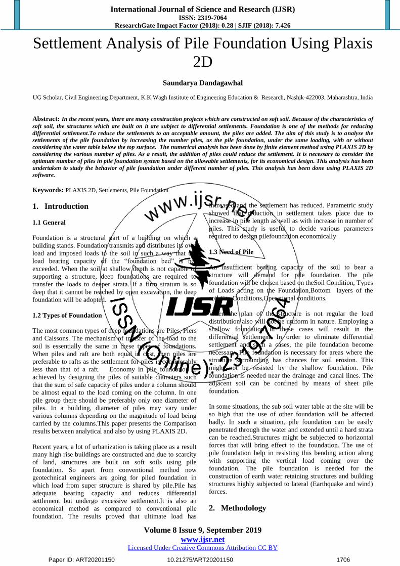
2.3 Procedure used for Simulation and Analysis of
Project:
Following flow chart expresses the procedure adopted for
the simulation of each model having unique position of pile:
Paper ID: ART20201150 10.21275/ART20201150 1707
International Journal of Science and Research (IJSR) ISSN: 2319-7064
ResearchGate Impact Factor (2018): 0.28 | SJIF (2018): 7.426
Volume 8 Issue 9, September 2019
www.ijsr.net Licensed Under Creative Commons Attribution CC BY
Figure 1: Flow chart showing procedure used for simulation and analysis of pile
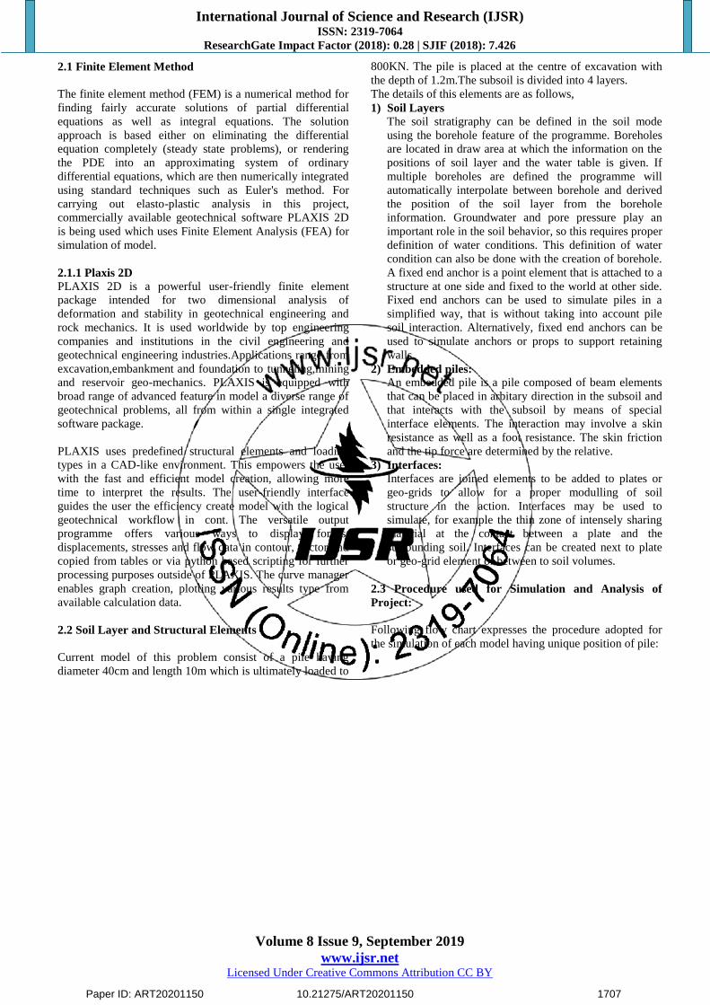
2.4 Problem Statement
1) Pile is placed at the center of small excavation with the
depth of 1.2m . The subsoil can be divided into 4 layers.
2) The water table is in level with the top of deep sand layer
which starts below pile toe.
3) The pile diameter is 40cm length is 10m which is
ultimately loaded to failure in compression.
Figure 1: Numerical structure
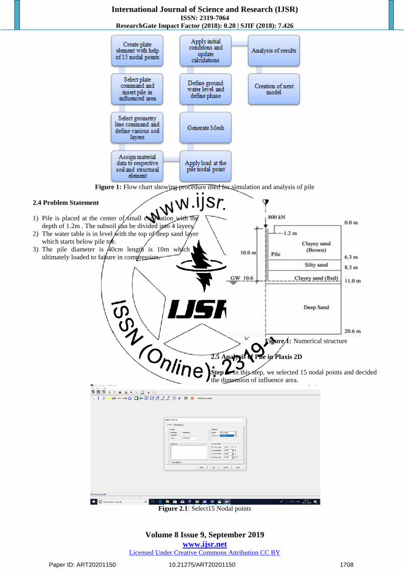
2.5 Analysis of Pile in Plaxis 2D
Step 1: In this step, we selected 15 nodal points and decided
the dimension of influence area.
Figure 2.1: Select15 Nodal points
Paper ID: ART20201150 10.21275/ART20201150 1708
International Journal of Science and Research (IJSR) ISSN: 2319-7064
ResearchGate Impact Factor (2018): 0.28 | SJIF (2018): 7.426
Volume 8 Issue 9, September 2019
www.ijsr.net Licensed Under Creative Commons Attribution CC BY
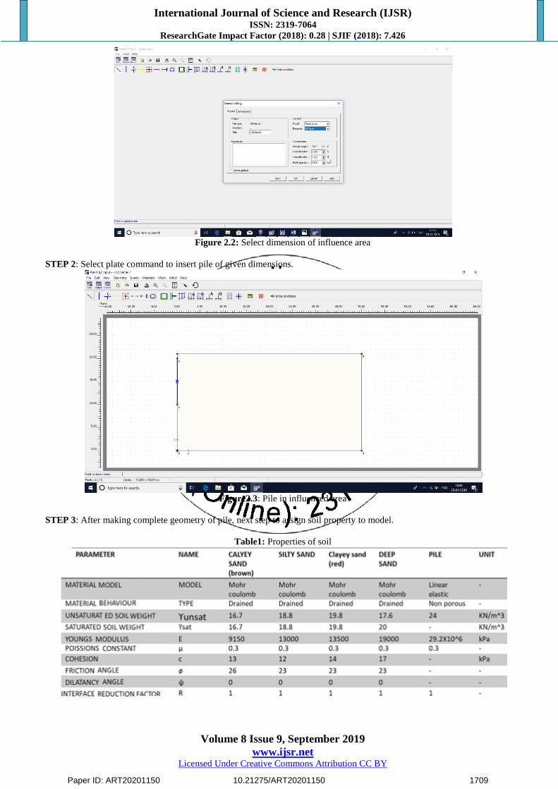
Figure 2.2: Select dimension of influence area
STEP 2: Select plate command to insert pile of given dimensions.
Figure2.3: Pile in influenced area
STEP 3: After making complete geometry of pile, next step to assign soil property to model.
Table1: Properties of soil
Paper ID: ART20201150 10.21275/ART20201150 1709

International Journal of Science and Research (IJSR) ISSN: 2319-7064
ResearchGate Impact Factor (2018): 0.28 | SJIF (2018): 7.426
Volume 8 Issue 9, September 2019
www.ijsr.net Licensed Under Creative Commons Attribution CC BY
Figure2.4: Assign properties to structural element (pile )
STEP 4: After giving input to soil layer, there properties were assigned.
Figure2.5: Material property assigning to soil
STEP 5: Next step is to assign load at pile nodal point
Figure2.6: Assign point load on nodal point
STEP 6: MESH IS GENERATED
Paper ID: ART20201150 10.21275/ART20201150 1710
International Journal of Science and Research (IJSR) ISSN: 2319-7064
ResearchGate Impact Factor (2018): 0.28 | SJIF (2018): 7.426
Volume 8 Issue 9, September 2019
www.ijsr.net Licensed Under Creative Commons Attribution CC BY
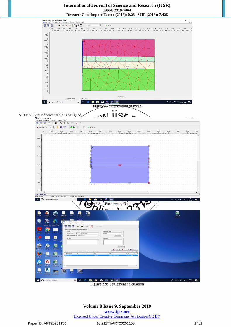
Figure2.7: Generation of mesh
STEP 7: Ground water table is assigned.
Figure2.8: Generation ground water table
Figure 2.9: Settlement calculation
Paper ID: ART20201150 10.21275/ART20201150 1711
International Journal of Science and Research (IJSR) ISSN: 2319-7064
ResearchGate Impact Factor (2018): 0.28 | SJIF (2018): 7.426
Volume 8 Issue 9, September 2019
www.ijsr.net Licensed Under Creative Commons Attribution CC BY
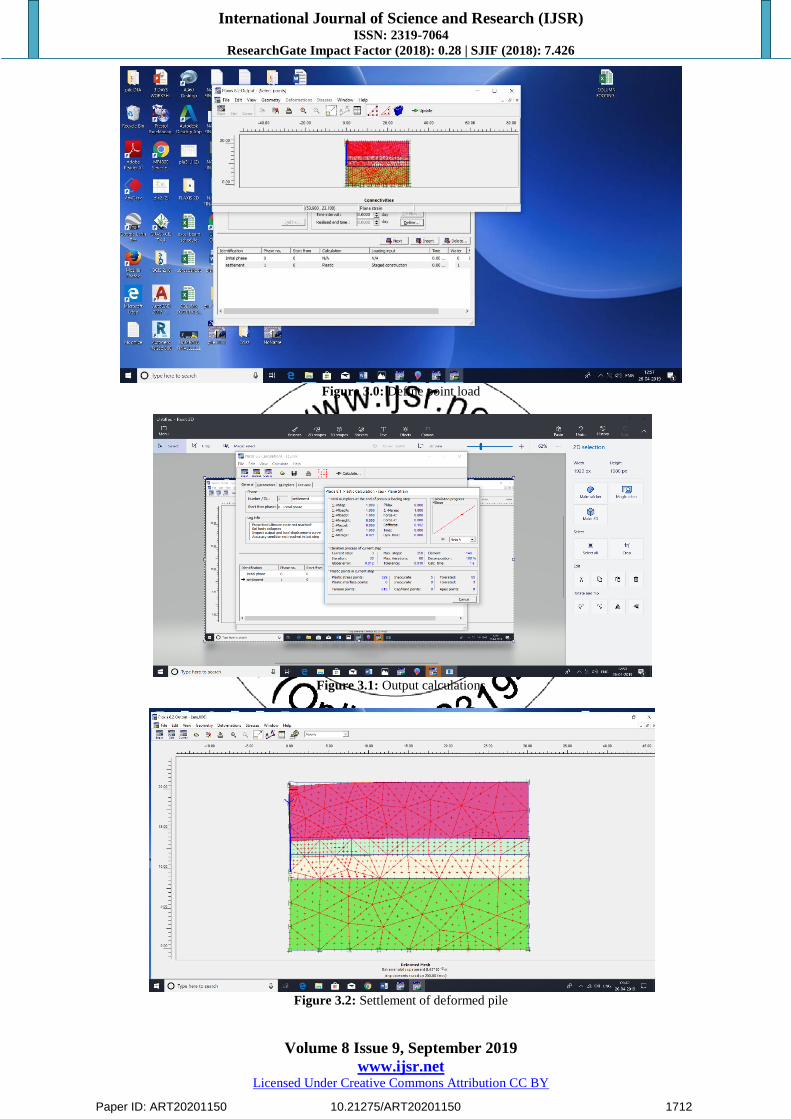
Figure 3.0: Define point load
Figure 3.1: Output calculations
Figure 3.2: Settlement of deformed pile
Paper ID: ART20201150 10.21275/ART20201150 1712

International Journal of Science and Research (IJSR) ISSN: 2319-7064
ResearchGate Impact Factor (2018): 0.28 | SJIF (2018): 7.426
Volume 8 Issue 9, September 2019
www.ijsr.net Licensed Under Creative Commons Attribution CC BY
Figure 3.3: Total settlement graph
Figure3.4: Graph of axial forces
Figure 3.5: Graph of bending moments
Paper ID: ART20201150 10.21275/ART20201150 1713
International Journal of Science and Research (IJSR) ISSN: 2319-7064
ResearchGate Impact Factor (2018): 0.28 | SJIF (2018): 7.426
Volume 8 Issue 9, September 2019
www.ijsr.net Licensed Under Creative Commons Attribution CC BY
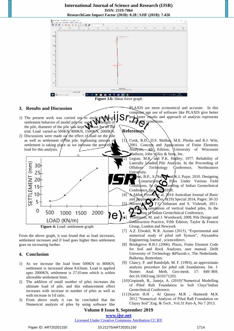
Figure 3.6: Shear force graph
3. Results and Discussion
1) The present work was carried out to study the load-
settlement behavior of model pile on sand. The length of
the pile, diameter of the pile was kept constant for all the
trial. Load varied as 500KN, 800KN, 1500KN, 2000KN.
2) Discussions were made on the effect of load on the pile
as well as settlement of the pile. Increasing amount of
settlement is taking place as we increase the prescribed
load for this analysis.
Figure 4: Load- settlement graph
From the above graph, it was found that as load increases,
settlement increases and if load goes higher then settlement
goes on increasing further.
4. Conclusion
1) As we increase the load from 500KN to 800KN,
settlement is increased about 8.63mm. Load is applied
upto 2000KN, settlement is 27.01mm which is within
allowable settlement limit.
2) The addition of small number of piles increases the
ultimate load of pile, and this enhancement effect
increases with increase in number of piles as well as
with increase in l/d ratio.
3) From above study it can be concluded that the
Numerical analysis of piles by using software like
PLAXIS are more economical and accurate. In this
computer age use of software like PLAXIS give better
and faster results and approach of analysis represents
actual soil conditions.
References
[1] Cook, R.D., D.S. Malkus, M.E. Plesha and R.J. Witt,
2001. Concept and Applications of Finite Elements
Analysis, 4th Edition, University of Wisconsin
Madison, John Wiley & Sons, Inc.
[2] Legian, M.K. and P.K. Hadley, 1977. Reliability of
Laterally Loaded Pile Analysis. In the Proceeding of
Offshore Technology Conference, Northeastern
University.
[3] Naveen, B.P., S. Nayak and K.L Pujar, 2010. Designing
and Construction of Piles Under Various Field
Conditions. In the Proceeding of Indian Geotechnical
Conference, pp: 1035-1038.
[4] A.Akbar Firoozi et al, 2014 Australian Journal of Basic
and Applied Sciences, 8(19) Special 2014, Pages: 30-33
[5] Naveen, B.P., T.G Sitharam and S. Vishruth, 2011.
Numerical simulation of vertical loaded piles, In the
Proceeding of Indian Geotechnical Conference,
[6] Tomlinson, M. and J. Woodward, 2008. Pile Design and
Construction Practice, Fifth Edition, Taylor & Francis
Group, London and Newyork
[7] A.Z. Elwakil, W.R. Azzam (2015), “Experimental and
numerical study of piled raft System”, Alexandria
Engineering Journal , sciencedirect.
[8] Brinkgreve R.B.J (2006). Plaxis, Finite Element Code
for Soil and Rock Analyses, user manual. Delft
University of Technology &Plaxisb.v, The Nederlands.
Balkema, Rotterdam.
[9] Clancy, P. and Randolph, M. F. (1993), an approximate
analysis procedure for piled raft foundations. Int. J.
Numer. Anal. Meth. Geo-mesh. 17: 849–869.
doi:10.1002/nag.1610171203.
[10] Gopinath, B., Juneja, A. (2010)"Numerical Modelling
of Piled Raft Foundation in Soft Clays"Indian
Geotechnical Conference.
[11] Karim H.H , Al Qaussy M.R , Hameedi M.K
2012.“Numerical Analysis of Piled Raft Foundation on
Clayey Soil”.Eng. & Tech , Vol.31 Part-A, No 7 2013.
Paper ID: ART20201150 10.21275/ART20201150 1714