setting up the viprion platform
TRANSCRIPT

Setting Up the VIPRION™ Platform
MAN-0265-01


Setting Up the VIPRIONTM Platform i
Product VersionThis manual applies to the VIPRION™ hardware platform and BIG-IP® software created by F5 Networks, Inc.
Publication DateThis guide was published on April 11, 2008.
Legal Notices
CopyrightCopyright 2008, F5 Networks, Inc. All rights reserved.
F5 Networks, Inc. (F5) believes the information it furnishes to be accurate and reliable. However, F5 assumes no responsibility for the use of this information, nor any infringement of patents or other rights of third parties which may result from its use. No license is granted by implication or otherwise under any patent, copyright, or other intellectual property right of F5 except as specifically described by applicable user licenses. F5 reserves the right to change specifications at any time without notice.
TrademarksF5, F5 Networks, the F5 logo, BIG-IP, 3-DNS, Acopia, Acopia Networks, Application Accelerator, Ask F5, Application Security Manager, ASM, ARX, ControlPoint, Data Guard, Enterprise Manager, EM, F5 Management Pack, FirePass, FreedomFabric, Global Traffic Manager, GTM, iControl, Internet Control Architecture, IP Application Switch, iRules, Link Controller, LC, Local Traffic Manager, LTM, Message Security Module, MSM, NetCelera, OneConnect, Packet Velocity, SSL Accelerator, SYN Check, Traffic Management Operating System, TMOS, TrafficShield, Transparent Data Reduction, uRoam, VIPRION, WANJet, WebAccelerator, and ZoneRunner, are trademarks or service marks of F5 Networks, Inc., in the U.S. and other countries, and may not be used without F5's express written consent.
PatentsThis product protected by U.S. Patents 6,327,242, 6,374,300; 6,473,802; 6,970,933; 7,051,126; 7,102,996; 7,146,354; 7,197,661; 7,206,282; 7,287,084. Other patents pending.
Export Regulation NoticeThis product may include cryptographic software. Under the Export Administration Act, the United States government may consider it a criminal offense to export this product from the United States.
RF Interference WarningThis is a Class A product. In a domestic environment this product may cause radio interference, in which case the user may be required to take adequate measures.
FCC ComplianceThis equipment has been tested and found to comply with the limits for a Class A digital device pursuant to Part 15 of FCC rules. These limits are designed to provide reasonable protection against harmful interference when the equipment is operated in a commercial environment. This unit generates, uses, and can radiate radio frequency energy and, if not installed and used in accordance with the instruction manual, may cause harmful interference to radio communications. Operation of this equipment in a residential area is likely to cause harmful interference, in which case the user, at his own expense, will be required to take whatever measures may be required to correct the interference.
Any modifications to this device, unless expressly approved by the manufacturer, can void the user's authority to operate this equipment under part 15 of the FCC rules.

ii
Canadian Regulatory ComplianceThis Class A digital apparatus complies with Canadian ICES-003.
Standards ComplianceThis product conforms to the IEC, European Union, ANSI/UL and Canadian CSA standards applicable to Information Technology products at the time of manufacture.
VCCI Class A ComplianceThis is a Class A product. In a domestic environment, this product may cause radio interference, in which case the user may be required to take corrective actions.

Table of Contents


Table of Contents
Setting Up the VIPRIONTM Platform v
1Getting Started with the VIPRION Platform
Introducing the VIPRION platform .............................................................................................1-1Getting started ................................................................................................................................1-2Power prerequisites .......................................................................................................................1-2
Components provided with the VIPRION platform .....................................................1-2Peripheral hardware that you provide ..............................................................................1-3
Familiarizing yourself with the VIPRION platform ..................................................................1-4Using the chassis ....................................................................................................................1-4Using blades ............................................................................................................................1-4About clustered technology ................................................................................................1-4
Finding additional information ......................................................................................................1-5Stylistic conventions .......................................................................................................................1-6
Using the solution examples ...............................................................................................1-6Identifying new terms ............................................................................................................1-6Identifying references to objects, names, and commands ............................................1-6Identifying references to other documents .....................................................................1-6Identifying command syntax ................................................................................................1-7
Finding help and technical support resources ..........................................................................1-8
2Unpacking the Chassis
Removing the chassis from its packaging ...................................................................................2-1
3Installing the Chassis in a Rack
Installing the chassis ........................................................................................................................3-1Powering the platform ...................................................................................................................3-6Attaching the LCD component to the chassis .........................................................................3-8
4Adding Blades
Installing a blade ...............................................................................................................................4-1
5Licensing the Platform
Assigning a cluster IP address ......................................................................................................5-1Licensing the platform ....................................................................................................................5-2Verifying blade availability ..............................................................................................................5-2
Glossary
Index

Table of Contents
vi

1
Getting Started with the VIPRION Platform
• Introducing the VIPRION platform
• Getting started
• Power prerequisites
• Familiarizing yourself with the VIPRION platform
• Finding additional information
• Stylistic conventions
• Finding help and technical support resources


Getting Started with the VIPRION Platform
Setting Up the VIPRIONTM Platform 1 - 1
Introducing the VIPRION platformThe VIPRION™ platform provides you with the flexibility and feature-rich capabilities of F5 products on a powerful and highly-extensible hardware platform. With this platform, you install and configure multiple F5 products using blades that are hot-swappable, which provides you with the ability to add, remove, or change the platform’s configuration as best fits your network.
This guide is designed to provide you with step-by-step instructions for unpacking the VIPRION platform and installing it into a rack. We highly recommend that you review this document before unpacking the platform, to ensure that you handle the unit safely. After following the steps in this guide, you should have a powered VIPRION platform installed in a rack, and be ready to configure the BIG-IP software.
Note
While this document describes many aspects of the VIPRION platform, it does not provide detailed product and environment specifications. For this information, see the Platform Guide: VIPRIONTM.
Important
The VIPRION platform is very heavy; in all situations in which you need to move or manipulate the platform, we highly recommend that you employ at least two people, to ensure that the unit is handled safely.
Figure 1.1 The VIPRION platform

Chapter 1
1 - 2
Getting startedThere are several basic tasks you must complete to get the VIPRION platform installed and set up.
• Review the hardware requirements. For more information about the hardware requirements, read the following sections, Components provided with the VIPRION platform, following, and Peripheral hardware that you provide, on page 1-3.
• Familiarize yourself with the VIPRION hardware. For more information, see Familiarizing yourself with the VIPRION platform, on page 1-4.
• Connect the VIPRION platform to the network, and optionally connect the peripheral hardware.
The VIPRION platform comes with the hardware that you need for installation. However, you must also provide standard peripheral hardware, such as a serial terminal, if you want to administer the VIPRION platform directly.
Power prerequisitesThe chassis supports one to four power supplies. The power supplies are auto-ranging 90VAC to 264VAC input.
Each power supply can provide up to 1200W of power at low-line input (90-140 VAC), and up to 2000W at high-line input (180-264 VAC). One power supply with low-line input can support two blades with no redundancy. The same power supply can support up to three blades with high-line AC input. If a standard chassis is configured with two AC power supplies, and they are plugged into 110VAC (low-line input) then the chassis can support four 600W line cards with no redundancy. Adding more power supplies provides levels of redundancy; should one power supply fail, the system can still operate using the remaining power supplies until you can add a replacement power supply.
Components provided with the VIPRION platformWhen you unpack the VIPRION platform, you should make sure that the following components are included:
• Four power cables
• Two mounting brackets
• Four mounting handles
• Eight rack mount screws
• One electrical static discharge (ESD) strap

Getting Started with the VIPRION Platform
Setting Up the VIPRIONTM Platform 1 - 3
The power cables supplied with the hardware are 220VAC high-line input cables that require a NEMA 6-20P wall outlet. For low-line input, you can order a 115V 20 AMP NEMA 5-20P cable.
Note
The power cables included with this unit are for exclusive use with this unit and should not be used with other electrical appliances.
Peripheral hardware that you provideFor the VIPRION platform, the peripheral hardware you provide is determined by the configuration you want to create:
◆ If you plan to use direct administrative access to the VIPRION platform, you need standard input/output hardware. This requires a serial terminal.
◆ If you want to use the default VIPRION platform configuration, you must have an administrative workstation on the same IP network as the platform.
◆ You also need network hubs, switches, or concentrators to connect to the VIPRION platform network interfaces. The devices you select must be compatible with the network interface cards installed in the VIPRION platform.
• Ethernet requires either a 10 Mbps or 100 Mbps hub or switch.
• Gigabit Ethernet requires a compatible Gigabit Ethernet switch.
• 10 Gigabit Ethernet requires a compatible 10 Gigabit Ethernet switch.
If you plan on doing remote administration from your own PC workstation, as most users do, we recommend that you have your workstation already in place on the same subnet to which the management interface is connected.

Chapter 1
1 - 4
Familiarizing yourself with the VIPRION platformThe VIPRION platform includes two primary components: the chassis, which houses the components, and blades, which reside within the chassis and provide the hardware and software needed to manage network traffic.
Using the chassisThe VIPRION chassis is the housing unit that contains all of the components necessary for the VIPRION platform to operate effectively. One of the most powerful features of the VIPRION platform is that you can add, remove, or change any or all of the essential components of the platform. These components include blades, power supplies, the fan tray, the LCD panel, and the System ID (SID) card. This configuration allows for an extremely robust and flexible system that can manage large amounts of application traffic and remain operational even if one of its components goes offline.
Using bladesA blade is the primary component that handles the traffic management within the VIPRION platform. You can install up to four blades in a single VIPRION chassis. These blades can exist in a single group, called a cluster. In instances where you do not have a blade for a given slot in the VIPRION chassis, the chassis includes blanks, which help maintain the airflow within the platform and ensure electromagnetic compliance (EMC).
About clustered technologyThe BIG-IP system's cluster technology means that all blades in the cluster function as one high-performance BIG-IP system. A cluster is a group of slots on the VIPRION chassis. Each slot in the cluster is considered to be a cluster member, and any blades that you insert into the slots of a cluster work together as a single system to process application traffic. At all times, one of the slots functions as the primary slot, accepting management and application traffic requests and dispersing the workload to blades in other slots in the cluster. With cluster technology, you use the power of multiple blades, but manage the entire cluster as if it were a single system.

Getting Started with the VIPRION Platform
Setting Up the VIPRIONTM Platform 1 - 5
Finding additional informationIn addition to this guide, there are other sources of documentation you can use in order to work with the VIPRION platform. This information is available from the Ask F5SM web site (https://support.f5.com), in the guides listed below:
◆ Platform Guide: VIPRIONTM
This guide provides you with detailed information about the VIPRION platform, as well as its components and specifications.
◆ Configuration Guide for the VIPRIONTM SystemThis guide contains information on how to implement the cluster-specific features of the BIG-IP software.
◆ Configuration Guide for BIG-IP® Local Traffic ManagementThis guide contains any information you need for configuring the BIG-IP software to manage local network traffic. With this guide, you can perform tasks such as creating virtual servers and load balancing pools, configuring application and persistence profiles, implementing health monitors, and setting up remote authentication.
◆ BIG-IP® Network and System Management GuideThis guide contains any information you need to configure and maintain the network and system-related components of the BIG-IP software. With this guide, you can perform tasks such as configuring VLANs, assigning self IP addresses, creating administrative user accounts, and managing a redundant system.
◆ BIG-IP® Command Line Interface GuideThis guide contains information you need if you choose to configure the BIG-IP system using the command line interface instead of the Configuration utility. It includes instructions for handling specific tasks, but it does not include instructions for configuring every aspect of the system. It also contains an appendix with detailed information about the bigpipe commands.

Chapter 1
1 - 6
Stylistic conventionsTo help you easily identify and understand important information, our documentation uses the stylistic conventions described below.
Using the solution examplesAll examples in this documentation use only private class IP addresses. When you set up the solutions we describe, you must use valid IP addresses suitable to your own network in place of our sample addresses.
Identifying new termsTo help you identify sections where a term is defined, the term itself is shown in bold italic text. For example, a virtual server is a specific combination of a virtual address and virtual port, associated with a content site that is managed by a BIG-IP system or other type of host server.
Identifying references to objects, names, and commandsWe apply bold text to a variety of items to help you easily pick them out of a block of text. These items include web addresses, IP addresses, utility names, and portions of commands, such as variables and keywords. For example, with the bigpipe pool <pool_name> show command, you can specify a specific pool to show by specifying a pool name for the <pool_name> variable.
Identifying references to other documentsWe use italic text to denote a reference to another document. In references where we provide the name of a book as well as a specific chapter or section in the book, we show the book name in bold, italic text, and the chapter/section name in italic text to help quickly differentiate the two.
For example, you can find information about SNMP traps in Appendix A, Troubleshooting SNMP Traps, in the BIG-IP® Network and System Management Guide.
Getting Started with the VIPRION Platform
Setting Up the VIPRIONTM Platform 1 - 7
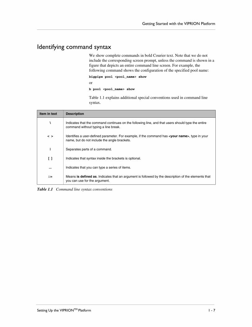
Identifying command syntaxWe show complete commands in bold Courier text. Note that we do not include the corresponding screen prompt, unless the command is shown in a figure that depicts an entire command line screen. For example, the following command shows the configuration of the specified pool name:
bigpipe pool <pool_name> show
or
b pool <pool_name> show
Table 1.1 explains additional special conventions used in command line syntax.
Item in text Description
\ Indicates that the command continues on the following line, and that users should type the entire command without typing a line break.
< > Identifies a user-defined parameter. For example, if the command has <your name>, type in your name, but do not include the angle brackets.
| Separates parts of a command.
[ ] Indicates that syntax inside the brackets is optional.
... Indicates that you can type a series of items.
::= Means is defined as. Indicates that an argument is followed by the description of the elements that you can use for the argument.
Table 1.1 Command line syntax conventions

Chapter 1
1 - 8
Finding help and technical support resourcesYou can find additional technical documentation and product information in the following locations:
◆ Online helpThe Configuration utility has online help for each screen. The online help contains descriptions of each control and setting on the screen. Click the Help tab in the left navigation pane to view the online help for a screen.
◆ Welcome screen in the Configuration utilityThe Welcome screen in the Configuration utility contains links to many useful web sites and resources, including:
• The F5 Networks Technical Support web site
• The F5 Solution Center
• The F5 DevCentral web site
• Plug-ins, SNMP MIBs, and SSH clients
◆ F5 Networks Technical Support web siteThe F5 Networks Technical Support web site, https://support.f5.com, provides the latest documentation for products, including:
• Release notes for the product, current and past
• Updates for guides (in PDF form)
• Technical notes
• Answers to frequently asked questions
• The Ask F5 Knowledge Base
To access this site, you need to register at https://support.f5.com.
For more information on how to configure the BIG-IP® system on the VIPRION platform, please see the Configuration Guide for the VIPRIONTM System. This guide provides detailed information on the unique characteristics of the VIPRION system. For information on the
different modules licensed for your platform, such as the BIG-IP® Local Traffic ManagerTM, please see the appropriate configuration guide for that module. These guides are available on the F5 Networks support site, https://support.f5.com.

2
Unpacking the Chassis
• Removing the chassis from its packaging


Unpacking the Chassis
Setting Up the VIPRIONTM Platform 2 - 1
Removing the chassis from its packagingThe VIPRION™ platform ships in a custom-designed package that protects the product during shipment and facilitates ease of removal when you are ready to install the platform in the rack. Due to the weight of the platform, there is a specific procedure that you must follow to ensure that you remove the platform from its packaging safely and securely.
Important
It is very important that you follow the steps outlined in this section when removing the platform. Failure to do so could result in personal injury or damage to the unit.
WARNING
The steps outlined in this section require that you remove the chassis from its shipping crate. To ensure your safety and to prevent damage to the chassis, we highly recommend that you have at least two people remove the chassis from the shipping crate.
To remove the chassis
1. If you have not already done so, open the top of the shipping crate (as shown in Figure 2.1).
Figure 2.1 The opened shipping crate of the VIPRION platform

Chapter 2
2 - 2
2. Remove the two smaller boxes located at the top of the box as shown in Figure 2.1. These boxes contain the LCD component, and accessories such as power cords.
Figure 2.2 The opened shipping crate without LCD panel and accessory boxes
3. Remove the protective cardboard and plastic covering located on top of the platform.
You should now see the top of the VIPRION platform, as seen in Figure 2.3. On either side, close to the bottom of the platform, are two handles. The VIPRION chassis rests on foam blocks, which in turn rest on a cardboard platform in which these handles are located.

Unpacking the Chassis
Setting Up the VIPRIONTM Platform 2 - 3
Figure 2.3 Top view of the VIPRION platform in shipping crate
4. Using two people, have each person grasp one handle and lift the platform straight up, as shown in Figure 2.4.
Important: The chassis ships with four power supplies installed in the chassis. Consequently, the unit may tip unless it is properly supported.

Chapter 2
2 - 4
Figure 2.4 Lifting the VIPRION platform
You should now have the chassis out of the box, supported by the cardboard platform.

Unpacking the Chassis
Setting Up the VIPRIONTM Platform 2 - 5
Figure 2.5 Moving the VIPRION platform
5. Carefully move the chassis to a flat, level surface, and set it down.
You are now ready to install the chassis into a rack.

Chapter 2
2 - 6

3
Installing the Chassis in a Rack
• Installing the chassis
• Powering the platform
• Attaching the LCD component to the chassis


Installing the Chassis in a Rack
Setting Up the VIPRIONTM Platform 3 - 1
Installing the chassisAfter you have identified the intended location for the VIPRIONTM chassis, you can install the chassis into the rack. You should choose a location with adequate ventilation to allow sufficient airflow through the platform.
The VIPRION chassis includes a rackmount kit and a handle installation kit.
◆ The rackmount kit consists of two mounting brackets that you can attach at either the front, middle, or back of the platform, using the screws provided with the unit. The location at which you attach the rails depends on the configuration of the rack.
◆ The handle installation kit includes four handles and eight screws for attaching the handles to the VIPRION chassis. The handles make it easier to lift the chassis into position for mounting.
You must install the rackmount kit before you can install the handle kit to lift the chassis into position.
WARNING
If you have not yet removed the chassis from the shipping crate, we highly recommend that you have at least two people remove the chassis from the crate. This ensures your safety and prevents damage to the chassis. For more information, see Chapter 2, Unpacking the Chassis.
WARNING
This product is sensitive to electrostatic discharge (ESD). We recommend that when you install or maintain the unit, you use proper ESD grounding procedures and equipment.
Note
At this point, you are installing an empty chassis into your rack. We recommend that you select a location for the platform that is easy to access when adding or removing power supplies, the fan tray, or blades.
To install the rack mount kit
1. Locate the mounting brackets included with the chassis.These brackets, along with their corresponding screws, are in the accessory box included with the chassis.

Chapter 3
3 - 2
Figure 3.1 An example of the mounting brackets
2. Attach the mounting brackets to the appropriate location, the front, the middle, or rear, using a Phillips-head screwdriver and the provided screws.
Figure 3.2 Side view of the VIPRION platform showing the three possible locations for the rackmount brackets
3. After you install the rack mount kit, you can install the handle kit.

Installing the Chassis in a Rack
Setting Up the VIPRIONTM Platform 3 - 3
To install the handle kit
After the rack mount rails are mounted on the chassis, you can mount the handle kit on the chassis.
1. Locate the handle kit included with the chassis.These handles, along with their corresponding screws, are in a box included with the chassis. Remove the covers on the handles if they are installed. Figure 3.3 shows the handle mounting kit.
Figure 3.3 Contents of the handle mounting kit
2. Mount the two front handles on the screw holes in the rack mount rails.Figure 3.4 shows the handle mounting holes. Two screws are provided for each handle. Ensure the screws are tightened to 12-14 inch*lbs.

Chapter 3
3 - 4
Figure 3.4 Handle mounting holes in the rack mount ears
3. Mount the two back handles using the mounting holes provided on the back of the chassis.Figure 3.5 shows the mounting holes on the back of the chassis.
Figure 3.5 Handle mounting location on the rear of the chassis

Installing the Chassis in a Rack
Setting Up the VIPRIONTM Platform 3 - 5
4. After the handles are mounted, the chassis is ready to be installed in the rack.Figure 3.6 shows the front and back handles mounted on the chassis.
Figure 3.6 Side view of the chassis with handles mounted on the front and rear of the chassis
To mount the chassis into the rack
1. Make sure the handles are securely installed.
2. Using two or more people, lift the chassis to the appropriate location on the rack, and secure it to the rack with the included rackmount screws.
3. With the platform secure, you can now power the unit.For information about powering the unit, refer to the following procedure.

Chapter 3
3 - 6
Powering the platformThe platform ships with four power cords that you must use with the installed power supplies to power the unit. This section describes powering a unit with AC power supplies. For details about wiring DC power supplies, refer to the Platform Guide: VIPRION™.
Important
Do not use any power cords other than those specifically designed for the VIPRION platform.
To power the platform
1. On the back of the platform (see Figure 3.7), locate the power outlets that correspond to the locations of the power supplies. Each outlet is labeled to ensure that you connect each power cord to the appropriate outlet.
Figure 3.7 Power supply outlets with corresponding labels
2. Attach the power cord to the outlet until it is firmly seated, as shown in Figure 3.8.

Installing the Chassis in a Rack
Setting Up the VIPRIONTM Platform 3 - 7
Figure 3.8 Attaching a power cord
3. Plug the power cord into an approved power source.
4. Repeat this process for each power supply in the chassis.

Chapter 3
3 - 8
Attaching the LCD component to the chassisThe LCD component allows you to access several functions associated with the platform, such as configuring the management port for the system. The LCD component is located in one of the small boxes included in the main platform shipping crate.
To attach the LCD component
1. Grasp the LCD component on either side, using the indentations provided.
Note: Failure to use the indentations could result in pinched fingers.
2. Align the guide pins on the panel to the corresponding holes in the chassis (as shown in Figure 3.9).
Figure 3.9 Attaching the LCD component

Installing the Chassis in a Rack
Setting Up the VIPRIONTM Platform 3 - 9
3. Press the LCD component onto the corresponding connections at the front of the platform until it clicks into place.
Figure 3.10 Pressing the LCD component into position

Chapter 3
3 - 10

4
Adding Blades
• Installing a blade


Adding Blades
Setting Up the VIPRIONTM Platform 4 - 1
Installing a bladeThe VIPRION™ chassis supports up to four blades. When you initially receive the platform, the slots that can contain these blades are filled with blanks. Blanks are a framework designed to protect the unit from dust and other particles when a slot is not in use. In addition to protecting the chassis from dust, a blank must be installed in each empty slot to ensure proper airflow in the chassis. To add a new blade, you first remove the blank from the corresponding slot and then insert the correct blade.
Note
We recommend that you install blades into the chassis starting at the top slot and then in each subsequent empty slot.
WARNING
This product is sensitive to electrostatic discharge (ESD). We recommend that when you install or maintain the unit, you use proper ESD grounding procedures and equipment.
The first part of this process requires that you remove the blank that is located in the slot in which you want to install the blade. If the slot does not have a blank, you can skip this procedure.
To remove a blank
1. Select the slot in which you want to insert the blade.
2. Turn the compression screws, located on either side of the blank, until the locking indicator changes from green (locked), as shown in Figure 4.1, to red (unlocked), as shown in Figure 4.2.
Figure 4.1 A compression screw in the green (locked) position

Chapter 4
4 - 2
Figure 4.2 A compression screw in the red (unlocked) position
3. Grasp the two eject levers on the front of the blank and pull towards you as shown in Figure 4.3.You can now remove the blank from the slot, and add the new blade.
Figure 4.3 Extending an eject lever

Adding Blades
Setting Up the VIPRIONTM Platform 4 - 3
To install a blade
1. Extend the eject levers, located on each side of the blade, into the open position.
2. Carefully lift the blade and align the guide grooves on either side with the corresponding grooves on the interior of the slot as shown in Figure 4.4.
Figure 4.4 Aligning the blade in the slot
Important
Verify that the blade is aligned with these grooves; otherwise, the blade does not seat correctly in the platform.

Chapter 4
4 - 4
3. Slide the blade in until it is fully seated in the slot.
4. When the eject levers engage the chassis, press the eject levers on the blade towards the center of the blade until locked in place as shown in Figure 4.5.
Figure 4.5 Locking the blade into position
5. Turn the compression screws clockwise until they are completely secured to the platform in the green (locked) position, as shown in Figure 4.1, on page 4-1.
Note: The locking indicator on the compression screws turns green before the screws are completely secured to the platform; however, we highly recommend that you continue turning the screws until they are firmly secured.
6. Repeat this process with each blade until all blades are secured in the unit.

5
Licensing the Platform
• Assigning a cluster IP address
• Licensing the platform
• Verifying blade availability


Licensing the Platform
Setting Up the VIPRIONTM Platform 5 - 1
Assigning a cluster IP addressAfter you successfully install the VIPRIONTM platform and provide it with power, you must assign a management IP address to the cluster. The management IP address for the cluster is known as the cluster IP address. The cluster IP address allows you to access the Configuration utility to configure other aspects of the product, such as the product license, VLANs, trunks, and so on.
With the VIPRION platform, you assign cluster IP addresses on a per-cluster basis. Initially, all blades installed in the chassis belong to a single default cluster. As a result, during the initial setup, you need only assign a single cluster IP address.
To configure a cluster IP address
1. From the LCD panel, use the arrow buttons to select the System menu and then press the Check button.
2. Navigate to the Cluster menu, and then press the Check button.
3. Navigate to the Cluster Mgmt option, and then press the Check button.
4. Using the arrow buttons, select the Cluster IP option, and then press the Check button.A field appears in which you can supply the management IP address.
5. Use the arrow buttons to define the management IP address, and then press the Check button.
6. Press the X button to return to the Cluster Mgmt menu.
7. Repeat steps 4 through 6 to configure the Cluster IP Mask, and Gateway settings, respectively.
8. Navigate to the Commit option and then press the Check button.This option confirms that you want to implement the changes you defined for the Cluster IP, Cluster IP Mask, and Gateway settings.

Chapter 5
5 - 2
Licensing the platformOnce the cluster IP address is configured for the VIPRION platform, you can access the Configuration utility using SSL, to manage the platform and its corresponding components. The first task you must complete when you access the Configuration utility is to license the VIPRION platform for the appropriate BIG-IP® software.
To license the platform
1. Using a web browser, navigate to the cluster IP address that you assigned to the VIPRION platform. Use the following format where <cluster ip address> is the cluster IP address you created.
https://<cluster ip address>
2. To access the Configuration utility, type admin as the user name and admin as the password.If this is the first time you have accessed the Configuration utility, the first screen you see is the License screen.
3. Follow the instructions in the Configuration utility to license the VIPRION platform. For more information about licensing the system, click the Help tab.
Verifying blade availabilityAt this point, you have successfully installed the VIPRION platform, powered it, assigned it an IP address, and licensed it for use. Now you need to ensure that the blades you installed are recognized by the software and available for processing network traffic.
To verify blade availability
1. Using a web browser, navigate to the cluster IP address that you have assigned to the VIPRION platform.The Configuration utility opens.
2. On the Main tab of the navigation pane, expand System and then select Clusters.The main Clusters screen opens.
3. In the section Cluster Members, verify that all blades listed have a green circle icon in the Status column.The green circle icon indicates that the member is up and operational.

Licensing the Platform
Setting Up the VIPRIONTM Platform 5 - 3
You have now successfully installed a VIPRION platform and prepared it for use on your network. The next steps involve further configuring the platform with the trunks, VLANs, and self IP addresses necessary for it to manage your network traffic effectively.
For more information, see the Configuration Guide for the VIPRIONTM System. For information on virtual servers and other aspects of traffic management, see the Configuration Guide for BIG-IP® Local Traffic Management.

Chapter 5
5 - 4

Glossary


Glossary
Setting Up the VIPRIONTM Platform Glossary - 1
blade
A blade is a BIG-IP system designed to fit into a slot of a BIG-IP blade server chassis. Multiple blades within a chassis can work together to process traffic from a single virtual server.
blank
A blank is a protective framework that fills a slot in the chassis normally occupied by a blade. Blanks are used to protect the chassis and maintain airflow when a blade is not installed.
chassis
A chassis refers to the housing component of the VIPRION platform. The chassis holds all hot-swappable components, such as blades.
cluster
A cluster is a group of slots on the VIPRION system chassis. When you insert blades into the slots of a cluster, the blades function as a single system to process application traffic.
cluster IP address
A cluster IP address is a floating management IP address associated with the primary slot in a cluster. When the blade in the primary slot is removed or becomes unavailable, another slot in the cluster automatically becomes the primary slot, and the cluster IP address becomes associated with the new primary slot. You use this IP address to manage the cluster.
cluster mask
A cluster mask is the subnet mask that applies to the cluster management IP address.
compression screw
A compression screw ensures that a given VIPRION component is securely attached to the chassis. Each screw indicates by color whether the component is secured to the chassis: green, which indicates that the screw is secured to the chassis; and red, which indicates that the screw is unsecured.
Configuration utility
The Configuration utility is the browser-based application that you use to configure the software.
eject levers
Eject levers refer to two levers located at the front of each blade or blank. These levers must be fully extended to remove the blade or blank from the chassis, and must be pressed securely against the chassis to ensure the component is seated correctly.

Glossary
Glossary - 2
guide grooves
A guide groove is a section within a chassis slot that helps ensure that blades are installed and seated correctly.
hot-swappable
Hot-swappable refers to your ability to remove a component without first shutting down the system. The VIPRION platform consists of several components including blades, the LCD component, power supplies, and the fan tray, that you can replace in a running system without affecting system performance.
LCD
LCD stands for liquid crystal display. An LCD panel is available on the front of the platform. You can use the LCD and its associated controls to configure the management port on the unit and view basic statistics.
LCD component
The LCD component is the hardware component that contains the LCD display and the LEDs that display power and alert status for the platform.

Index


Index
Setting Up the VIPRIONTM Platform Index - 1
Aaccessory box 2-2additional information, finding 1-5additional resources 1-8Ask F5 knowledge base 1-8
Bblade availability 5-2blades
and compression screws 4-1and eject levers 4-2installing and removing 4-1
blanks 4-1
Cchassis
and components provided 1-2removing and preventing damage 2-1
cluster IP addresses 5-1cluster members 1-4clusters 1-4, 5-1command line syntax table 1-7command syntax, identifying 1-7components provided with the chassis 1-2compression screws
securing 4-4unsecuring 4-1
Configuration utilityabout online help 1-8about the Welcome screen 1-8accessing 5-1, 5-2
Ddefault cluster 5-1documents, identifying 1-6
Eeject levers
engaging 4-4opening 4-2
electrostatic discharge. See ESD warning.EMC compliance 1-4ESD strap 1-2ESD warning 3-1, 4-1Ethernet hub requirements 1-3
GGigabit Ethernet 1-3guide grooves, for blades 4-3
Hhardware requirements
for components 1-2for peripherals 1-3
help, online 1-8hubs 1-3
Iinjury
avoiding 2-1, 3-8
LLCD box 2-2LCD panel
and indentations 3-8attaching 3-8
licenseconfiguring 5-2
Mmanagement IP addresses
See cluster IP addresses.mounting brackets 3-1
NNetwork and System Management guide 1-5new terms, identifying 1-6
Oonline help 1-8
Pplatform
lifting 1-1, 2-3preventing damage 2-1
platform accessory box 2-2platform packaging 2-1platform weight 2-1power
and cabling 1-3power cords
as accessories 2-2attaching 3-7
power requirements 1-2power supplies 1-2
and inputs 1-2and power input 1-2as accessories 2-3
primary slot 1-4product information, finding 1-8

Index
Index - 2
Rrack location 3-1rackmount kits 3-1racks
and platform installation 3-1rail location 3-1references
identifying 1-6to commands 1-6
remote administration 1-3
Ssafety 2-1serial terminal
and hardware installation 1-3SID card 1-4solution examples 1-6stylistic conventions 1-6switches 1-3syntax. See command syntax, identifying.System ID card 1-4
Ttechnical documentation, finding 1-8technical support web site 1-8
Uunit
preventing damage 2-1
WWelcome screen
about 1-8
