setting up the network server - erik
TRANSCRIPT
Setting Up the Network ServerInstalling and expanding the hardware
© 1996 Apple Computer, Inc. All rights reserved. Underthe copyright laws, this manual may not be copied, inwhole or in part, without the written consent of Apple.Your rights to the software are governed by theaccompanying software license agreement.
The Apple logo is a trademark of Apple Computer, Inc.,registered in the United States and other countries. Use ofthe “keyboard” Apple logo (Option-Shift-K) forcommercial purposes without the prior written consent ofApple may constitute trademark infringement and unfaircompetition in violation of federal and state laws.
Every effort has been made to ensure that the informationin this manual is accurate. Apple is not responsible forprinting or clerical errors.
Apple Computer, Inc.1 Infinite LoopCupertino, CA 95014(408) 996-1010
Apple, the Apple logo, AppleTalk, Apple SuperDrive,and Macintosh are trademarks of Apple Computer, Inc.,registered in the United States and other countries.
Apple Desktop Bus and Mac are trademarks of AppleComputer, Inc.
Adobe and PostScript are trademarks of Adobe SystemsIncorporated or its subsidiaries and may be registered incertain jurisdictions.
Helvetica and Times are registered trademarks ofLinotype Company.
IBM is a registered trademark of International BusinessMachines Corporation. AIX is a registered trademark ofInternational Business Machines Corporation and is beingused under license. InfoExplorer is a trademark ofInternational Business Machines Corporation.
NuBus is a trademark of Texas Instruments.
PowerPC is a trademark of International BusinessMachines Corporation, used under license therefrom.
Simultaneously published in the United States andCanada.
Mention of third-party products is for informationalpurposes only and constitutes neither an endorsement nora recommendation. Apple assumes no responsibility withregard to the performance or use of these products.
K Apple Computer, Inc.
Communications regulation information / vii
Laser information / viii
Preface: About This Guide / ix
1 Overview of Your Server / 1Components and features / 1
Your server at a glance / 2
Technical overview / 5
Expanding the Network Server / 6Choosing the right components / 6
Optimizing Network Server performance / 8
2 Installing Internal Server Components / 9Installing additional memory / 10
Installing PCI cards / 14Power requirements / 14Installing the card / 15
Installing internal SCSI drives / 21Installing a device driver / 22Setting the SCSI ID number / 23Installing Network Server SCSI drives in the front drive bays / 24Installing drives not from kits in the front drive bays / 26Installing drives in the rear-mounted bracket (700 model only) / 31Preparing a hard disk for use / 40Verifying internal SCSI devices / 40
Replacing or adding a power supply (700 model only) / 41
Replacing a fan / 44
Contents
3 Setting Up Your Server and Connecting External Devices / 45Important site considerations / 46
Electrical requirements / 46Temperature and airflow / 46
Security and safety issues / 47Physically isolating the system / 47Using a locking cable / 47Locking the door and rear drawer / 49
Locking and unlocking the wheels / 51
Installing the server in a rack / 53
Adding disk drives and other external SCSI devices / 56Installing a device driver / 56Setting the SCSI ID number / 56Connecting an external SCSI device / 57Preparing a hard disk for use / 59Verifying external SCSI devices / 60
Connecting a monitor / 61Connecting the monitor’s power cord / 62Connecting the monitor cable / 62
Connecting a system console / 64
Connecting the mouse and keyboard / 65
4 Connecting Your Server to the Network / 67Installing a networking card / 67
Connecting the built-in Ethernet (AAUI) port to the network / 68Connecting to thin coaxial Ethernet / 70Connecting to twisted-pair Ethernet / 71Connecting to other types of Ethernet / 72
iv Contents
Connecting the Apple PCI Ethernet Card to the network / 73Connecting the Apple PCI Ethernet Card to a thin coaxial network / 73Connecting the Apple PCI Ethernet Card to a twisted-pair network / 75Connecting the Apple PCI Ethernet Card to other types of Ethernet / 76Connecting the Apple PCI Ethernet 100BASE-TX Card to the network / 77Installing drivers for Apple PCI Ethernet Cards / 78
5 Starting Up Your Server / 81Plugging in the server / 82
Turning the server on / 84Problems turning on your server? / 87
Turning the server off under normal circumstances / 90
Restarting the server following a power interruption / 90
Turning the server off in an emergency / 91
6 Using CD-ROM and Tape Drives / 93Using the CD-ROM drive / 93
Inserting a CD-ROM disc / 93Ejecting a CD-ROM disc / 94
Using the tape drive / 95Compatible tapes / 95Starting up the tape drive / 96Inserting tape cassettes / 97Status lights / 97The caution signal / 98Removing tape cassettes / 98Forcing the ejection of a tape cassette / 99Locking a cassette / 99Avoiding high humidity / 99
Cleaning the tape-drive heads / 100
Contents v
Appendix A Safety, Maintenance, and Health Information / 101Important server safety instructions / 101
Handling your computer equipment / 102Handling the monitor / 103Handling the keyboard / 104Handling floppy disks / 104If you can’t eject a floppy disk / 105Power supply / 105
Cleaning your equipment / 106Cleaning the server case / 106Cleaning the monitor / 106Cleaning the mouse / 106
Health-related information about computer use / 108Musculoskeletal discomfort / 108Eye fatigue / 109Arranging your office / 110Avoiding fatigue / 111What about electromagnetic emissions? / 112
Appendix B Technical Information / 113Specifications / 113
DRAM configurations / 116Power requirements / 116Environment / 118
Appendix C Configuring the SCSI ID Cable / 119Connecting the SCSI ID cable for IBM and Seagate drives (2 GB and 4 GB) / 119
Rewiring and SCSI ID cable for Quantum drives and drives with active high LED / 120
Index / 121
vi Contents
Communications regulation information
Communications regulation information vii
FCC statement This equipment has been tested and found tocomply with the limits for a Class A digital devicepursuant to Part 15 of the Federal CommunicationsCommission (FCC) rules. These limits aredesigned to provide reasonable protection againstsuch interference when the equipment is operatedin a commercial environment. This equipmentgenerates, uses, and can radiate radio-frequencyenergy and, if not installed and used in accordancewith the instructions in this manual, may causeinterference to radio communications. Operation ofthis equipment in a residential area is likely tocause interference, in which case the user, at theuser’s own expense, will be required to correct theinterference.
IMPORTANT Changes or modifications to thisproduct are not authorized by Apple Computer,Inc., and could void the FCC certification andnegate your authority to operate the product. Thisproduct was tested for FCC compliance underconditions that included the use of shielded cablesand connectors between system components. It isimportant that you use shielded cables andconnectors to reduce the possibility of causinginterference to radios, television sets, and otherelectronic devices. For Apple peripheral devices,you can obtain the proper shielded cables throughan Apple-authorized dealer. For non-Appleperipheral devices, contact the manufacturer ordealer for assistance.
Industry Canada DOC Class A Compliance This class A digital device meets all requirementsof the Canadian Interference-Causing EquipmentRegulations.
Cet appareil numérique de la classe A respecte toutesles exigences du Réglement sur le matériel brouilleur duCanada..
VCCI statement
EU statement This equipment generates, uses, and may radiateradio-frequency energy and, if not properlyinstalled and used in accordance with theinstruction manual, may result in interference toradio communications.
This equipment has been designed, tested, andfound compliant with the Class A limits forInformation Technology Equipment of EN55022.These limits are designed to provide reasonableprotection against radio interference when theequipment is operated in a commercialenvironment.
viii Laser information
Laser information WARNING Making adjustments or performingprocedures other than those specified in yourequipment’s documentation may result inhazardous exposure.
WARNING Do not attempt to disassemble thecabinet containing the laser. The laser beamused in this product is harmful to the eyes.The use of optical instruments, such asmagnifying lenses, with this productincreases the potential hazard to your eyes.For your safety, have this equipment servicedonly by an Apple-authorized serviceprovider.
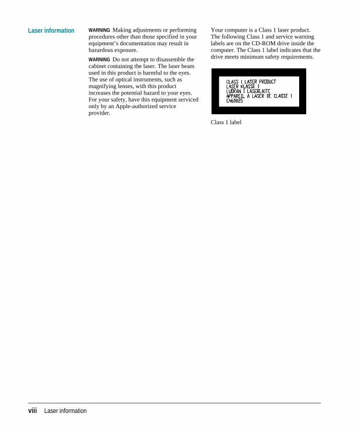
Your computer is a Class 1 laser product.The following Class 1 and service warninglabels are on the CD-ROM drive inside thecomputer. The Class 1 label indicates that thedrive meets minimum safety requirements.
Class 1 label
This guide tells you how to set up your Network Server and connect it to anEthernet network. The guide also provides information about expanding yourserver, using software, and troubleshooting problems that may arise.
About your Network Server
Your Network Server is powered by the PowerPC™ microprocessor. Thismicroprocessor was designed by Apple Computer, Inc., Motorola, Inc., andIBM Corporation. The PowerPC microprocessor uses Reduced Instruction SetComputer (RISC) technology to deliver very high performance at the lowestpossible cost. The PowerPC RISC microprocessor represents the state of theart in microprocessor design.
Your Network Server runs IBM’s AIX operating system, enabling you to usethe wide range of software applications available on AIX.
What you need to know
This guide is intended for the person, generally a system administrator ornetwork administrator, who sets up the server and connects it to an existingnetwork. Before you set up your Network Server and install the operatingsystem, you should be familiar with AIX. If you’re new to administering AIX,see Using AIX, AppleTalk Services, and Mac OS Utilities on the Network Server inyour server accessory kit for additional information. You need to know somedetails of your existing network to choose the appropriate procedures forconnecting the server to your network.
Preface About This Guide
What this guide contains
Here’s a brief summary of what you’ll find in this guide:
m Chapter 1, “Overview of Your Server,” gives server specifications andhighlights the Network Server’s features.
m Chapter 2, “Installing Internal Server Components,” describes how to addmemory to the server, install an expansion card, install additional SCSIdevices, such as hard drives, and replace or add a power supply.
m Chapter 3, “Setting Up Your Server and Connecting External Devices,”describes site preparation, shows how to mount the server in a rack,describes how to connect external SCSI devices, and explains how toconnect the monitor and keyboard.
m Chapter 4, “Connecting Your Server to the Network,” describes how toinstall Apple Ethernet cards and physically connect the server to anetwork.
m Chapter 5, “Starting Up Your Server,” describes how to power up yourserver and outlines the normal startup process. This chapter also suggestssolutions for problems that you might encounter during the startupprocess.
m Chapter 6, “Using CD-ROM and Tape Drives,” explains how to use thedrives and describes the compatible media.
m Appendix A, “Safety, Maintenance, and Health Information,” suggests howyou can set up your server as part of a healthful and safe workenvironment and how you can care for your equipment.
m Appendix B, “Technical Information,” gives the server specifications.
m Appendix C, “Configuring the SCSI ID Cable,” describes SCSI ID cablewiring for hard drives.
x Preface
How to use this guide
Familiarize yourself with your server’s basic components. See the section “YourServer at a Glance” in Chapter 1.
Consider security and safety issues and placement of your server. Read the sections“Important Site Considerations” and “Security and Safety Issues” in Chapter 3for important safety guidelines and information about protecting your serverfrom unauthorized access.
If you want to add an expansion card or internal drive to the server: Install thecard or internal device according to the instructions in Chapter 2, “InstallingInternal Server Components.”
If you want to connect external peripheral devices to your server: Turn to theappropriate instructions in Chapter 3.
Connect to the network to complete the setup process. See the section “Connectingto the Network” in Chapter 4 for details.
Be sure to read other sections of this guide that are relevant to your workenvironment. Also, be sure to keep this guide in a handy location; if youexperience problems while using your server, you may need to refer to thetroubleshooting information interspersed throughout this guide.
Preface xi
For more information
In addition to this guide, you may need to consult these sources of information:
m Using AIX, AppleTalk Services, and Mac OS Utilities on the Network Server.See this guide for information about the AIX operating system, includingsoftware installation, administration, and network configuration.
m Network Server PCI RAID Disk Array Card Set Up and Administration Guide.See this guide for information about the redundant array of independentdisks (RAID) controller.
m Related software and hardware guides. Your Network Server may comewith a variety of file and print services, backup utilities, and othersoftware. See the accompanying manuals for information about thesoftware that you’re using on the server.
See also the file /usr/lpp/bos/README which is described in the nextsection.
On-screen help and information
There are several valuable sources of help and information that you can viewdirectly on the screen of your server’s monitor.
/usr/lpp/bos/README file
It is important that you read the file /usr/lpp/bos/README, which containslate-breaking information about your server. This file is located on theInstallation CD in your server accessory kit. You may want to print this file forfuture reference.
AIX documentation through InfoExplorer™
When you are working with the AIX operating system, the InfoExplorernavigation tool enables you to look up information available in over 100 IBMbooks, including user’s guides and other reference material. The manualUsing AIX, AppleTalk Services, and Mac OS Utilities on the Network Serverprovides details on how to use the on-screen IBM documentation.
xii Preface
Components and features
The Network Server is a PowerPC™-based server that offers highperformance to medium and large workgroups running AIX-basedapplications. The Network Server simplifies hardware service and expansion,with an innovative design that enables you to replace or add hardwarecomponents quickly and easily. Some Network Server models also offerredundant power supplies that enable the server to continue running even ifone of the power supplies fails.
Note: The technical specifications in this chapter were accurate at the time of printing, but may have changed by the time your server shipped. See thefile /usr/lpp/bos/README for the latest information.
1 Overview of Your Server
Your server at a glance
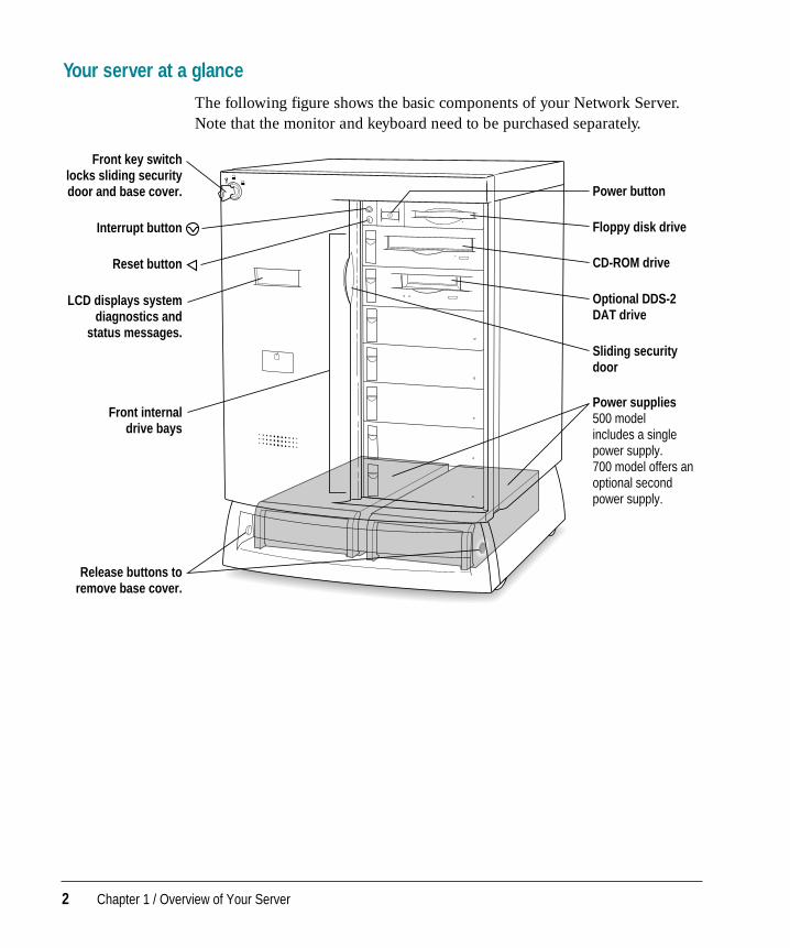
The following figure shows the basic components of your Network Server.Note that the monitor and keyboard need to be purchased separately.
Interrupt button
Front key switch locks sliding security door and base cover.
Reset button
LCD displays system diagnostics and
status messages.
Floppy disk drive
CD-ROM drive
Power button
Front internal drive bays
Release buttons to remove base cover.
Optional DDS-2 DAT drive
Sliding security door
Power supplies 500 model includes a single power supply. 700 model offers an optional second power supply.
2 Chapter 1 / Overview of Your Server
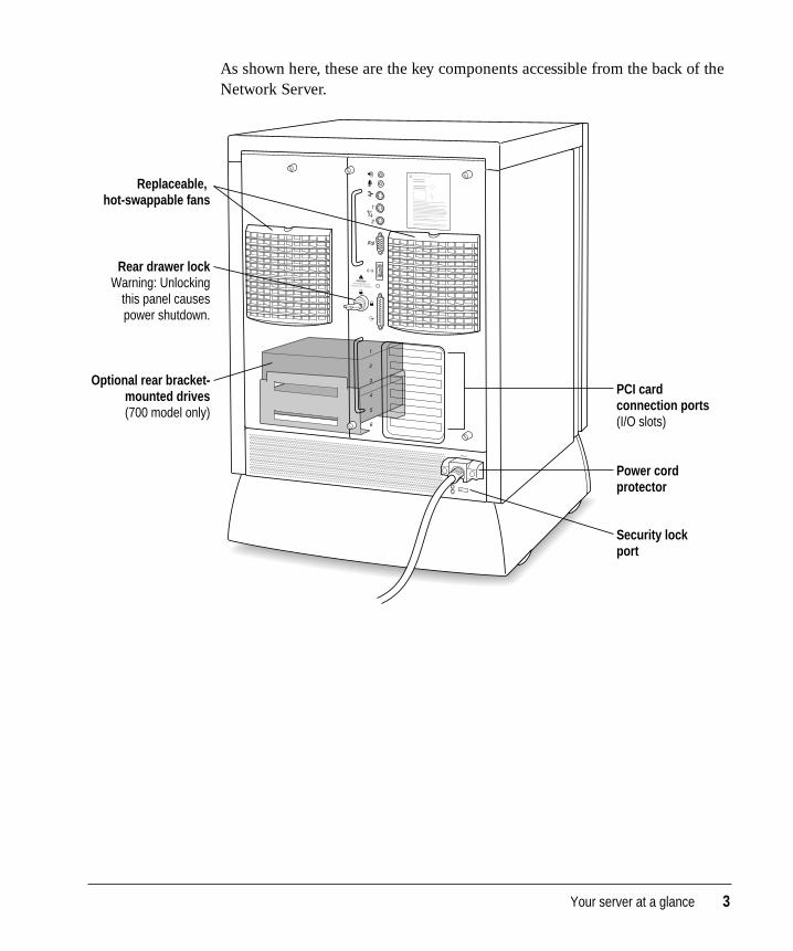
As shown here, these are the key components accessible from the back of theNetwork Server.
Optional rear bracket- mounted drives (700 model only)
Replaceable, hot-swappable fans
Power cord protector
PCI card connection ports (I/O slots)
Security lock port
Rear drawer lock Warning: Unlocking
this panel causes power shutdown.
Your server at a glance 3
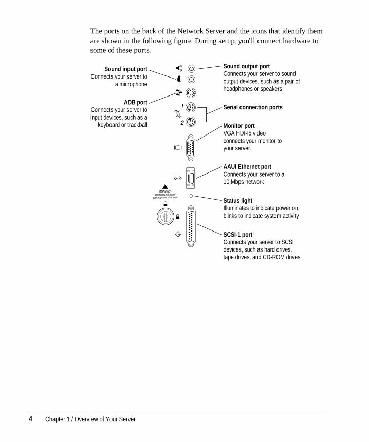
The ports on the back of the Network Server and the icons that identify themare shown in the following figure. During setup, you’ll connect hardware tosome of these ports.
Sound output port Connects your server to sound output devices, such as a pair of headphones or speakers
Serial connection ports
Sound input port Connects your server to
a microphone
Monitor port VGA HDI-I5 video connects your monitor to your server.
AAUI Ethernet port Connects your server to a 10 Mbps network
Status light Illuminates to indicate power on, blinks to indicate system activity
SCSI-1 port Connects your server to SCSI devices, such as hard drives, tape drives, and CD-ROM drives
ADB port Connects your server to input devices, such as a
keyboard or trackball
4 Chapter 1 / Overview of Your Server
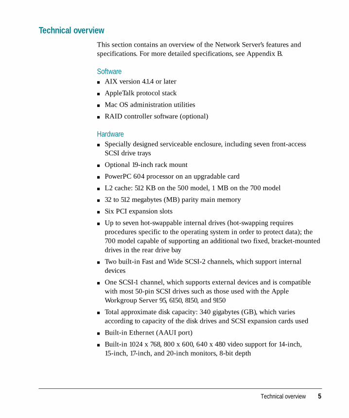
Technical overview
This section contains an overview of the Network Server’s features andspecifications. For more detailed specifications, see Appendix B.
Softwarem AIX version 4.1.4 or later
m AppleTalk protocol stack
m Mac OS administration utilities
m RAID controller software (optional)
Hardwarem Specially designed serviceable enclosure, including seven front-access
SCSI drive trays
m Optional 19-inch rack mount
m PowerPC 604 processor on an upgradable card
m L2 cache: 512 KB on the 500 model, 1 MB on the 700 model
m 32 to 512 megabytes (MB) parity main memory
m Six PCI expansion slots
m Up to seven hot-swappable internal drives (hot-swapping requiresprocedures specific to the operating system in order to protect data); the700 model capable of supporting an additional two fixed, bracket-mounteddrives in the rear drive bay
m Two built-in Fast and Wide SCSI-2 channels, which support internaldevices
m One SCSI-1 channel, which supports external devices and is compatiblewith most 50-pin SCSI drives such as those used with the AppleWorkgroup Server 95, 6150, 8150, and 9150
m Total approximate disk capacity: 340 gigabytes (GB), which variesaccording to capacity of the disk drives and SCSI expansion cards used
m Built-in Ethernet (AAUI port)
m Built-in 1024 x 768, 800 x 600, 640 x 480 video support for 14-inch, 15-inch, 17-inch, and 20-inch monitors, 8-bit depth
Technical overview 5
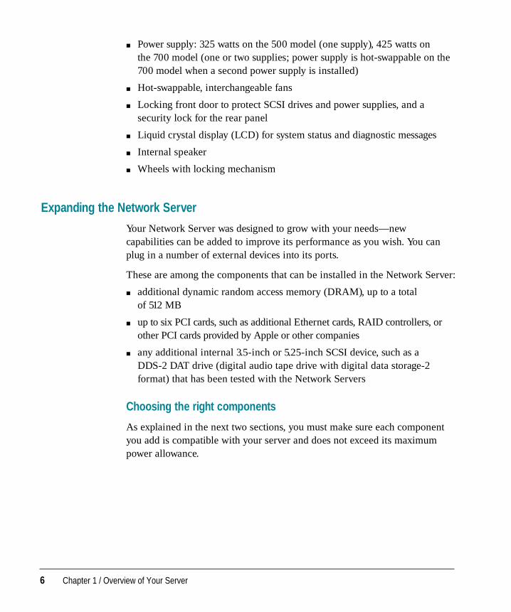
m Power supply: 325 watts on the 500 model (one supply), 425 watts on the 700 model (one or two supplies; power supply is hot-swappable on the700 model when a second power supply is installed)
m Hot-swappable, interchangeable fans
m Locking front door to protect SCSI drives and power supplies, and asecurity lock for the rear panel
m Liquid crystal display (LCD) for system status and diagnostic messages
m Internal speaker
m Wheels with locking mechanism
Expanding the Network Server
Your Network Server was designed to grow with your needs—newcapabilities can be added to improve its performance as you wish. You canplug in a number of external devices into its ports.
These are among the components that can be installed in the Network Server:
m additional dynamic random access memory (DRAM), up to a total of 512 MB
m up to six PCI cards, such as additional Ethernet cards, RAID controllers, orother PCI cards provided by Apple or other companies
m any additional internal 3.5-inch or 5.25-inch SCSI device, such as a DDS-2 DAT drive (digital audio tape drive with digital data storage-2format) that has been tested with the Network Servers
Choosing the right components
As explained in the next two sections, you must make sure each componentyou add is compatible with your server and does not exceed its maximumpower allowance.
6 Chapter 1 / Overview of Your Server
Compatibility
Your dealer or the manufacturer of a component can provide compatibilitydetails. However, you might find these points useful:
m The Network Server uses 72-bit-wide, 168-pin parity DRAM Dual InlineMemory Modules (DIMMs), which should be installed in matched pairs(for example, two 8 MB DIMMs). Your server’s DIMMs are fast-pagedmode, parity DRAM, with an access time of 60-nanoseconds or faster.Nonparity DIMMs with 70-nanosecond or faster access time DRAM willwork; however, if there is any nonparity DRAM installed, all server paritychecking is disabled.
Some DIMMs and all Single Inline Memory Modules (SIMMs) from olderMacintosh computers are not compatible. For more detailed information,see “DRAM Configurations” in Appendix B.
m The Network Server uses cards designed according to the PeripheralComponent Interconnect (PCI) standard. Your server cannot accommodateNuBus™ cards, which were designed for older Macintosh computers.
Power allowances
The Network Server meets Apple’s PCI power specifications. Check theinformation that came with your expansion card to make sure the card doesnot exceed these specifications.
For more detailed information, see “Expansion Cards and Devices” inAppendix B.
Expanding the Network Server 7
Optimizing Network Server performance
As you expand the Network Server by adding cards and devices such as harddrives, CD-ROM drives, tape drives, and the like, you can ensure best serverperformance by following these guidelines:
m When installing additional memory, use the correct type of parity DRAMDIMMs, and install DIMMs in pairs of the same size into paired slots (forexample, 1A and 1B) in your server.
m When installing PCI cards, such as additional Ethernet cards or other PCIcards provided by Apple or other companies, use the lowest available slotposition (bottom slot first). Check the RAID documentation for informationregarding slot placement for the RAID controller.
m When installing additional internal SCSI devices, balance the load betweenthe buses by matching the number of devices on each internal bus asclosely as possible.
For details on how to implement these performance guidelines, see thesections of this guide that describe procedures for installing and expandingyour server.
8 Chapter 1 / Overview of Your Server
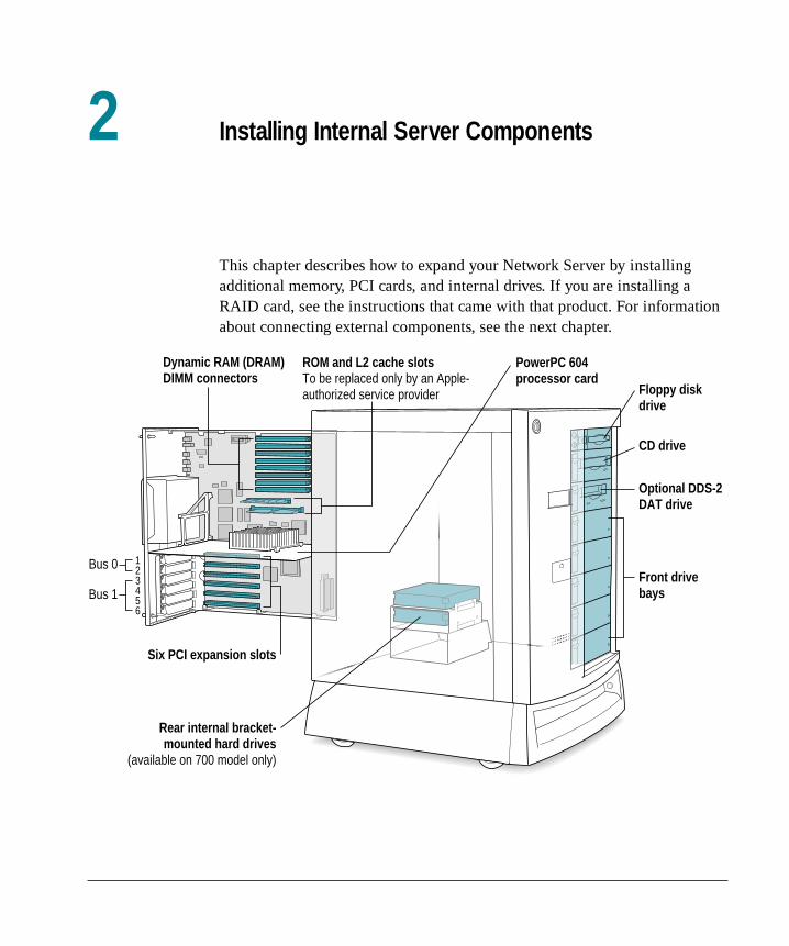
This chapter describes how to expand your Network Server by installingadditional memory, PCI cards, and internal drives. If you are installing aRAID card, see the instructions that came with that product. For informationabout connecting external components, see the next chapter.
Floppy disk drive
ROM and L2 cache slots To be replaced only by an Apple- authorized service provider
Six PCI expansion slots
PowerPC 604 processor card
1 2 3 4 5 6
Bus 0
Dynamic RAM (DRAM) DIMM connectors
Rear internal bracket- mounted hard drives
(available on 700 model only)
CD drive
Optional DDS-2 DAT drive
Front drive baysBus 1
2 Installing Internal Server Components
Installing additional memory
Additional dynamic random-access memory (DRAM) can be installed inyour Network Server. Memory for your server is provided in packages calledDRAM DIMMs. The DIMMs must be the correct type for your server. Theyshould be installed in matched pairs of the same size into paired slots (forexample, 1A and 1B) in your server in order to allow the memoryinterleaving that provides optimal system performance. It is very importantthat the DRAM DIMMs be correctly installed. Incorrect installation canresult in errors, unpredictable results, and damage to your equipment and data.
In addition to the DRAM DIMM kit, you’ll also need these items:
m a grounding wrist strap
m an antistatic mat
To install DRAM DIMMs:
1 If the server is running, shut down the operating system, turn the server off, and unplug it.
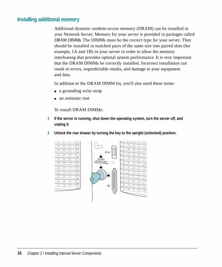
2 Unlock the rear drawer by turning the key to the upright (unlocked) position.
10 Chapter 2 / Installing Internal Server Components
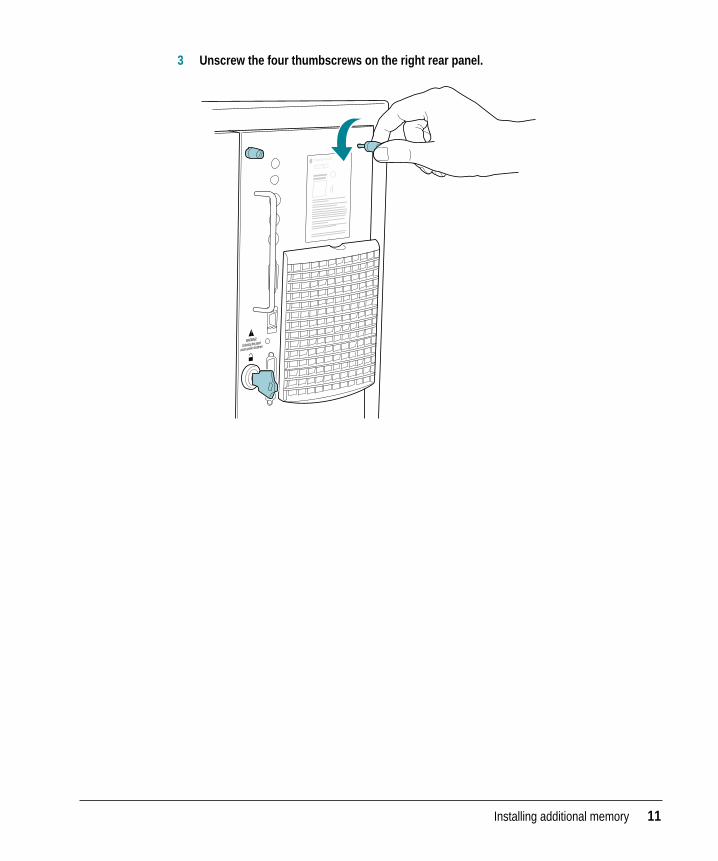
3 Unscrew the four thumbscrews on the right rear panel.
Installing additional memory 11
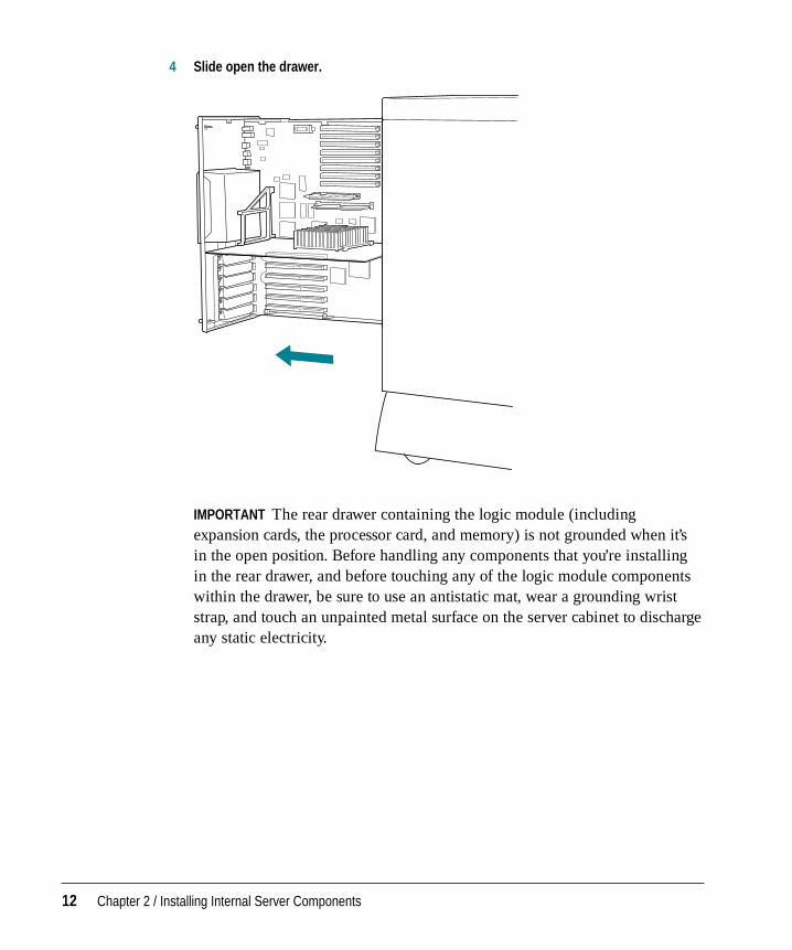
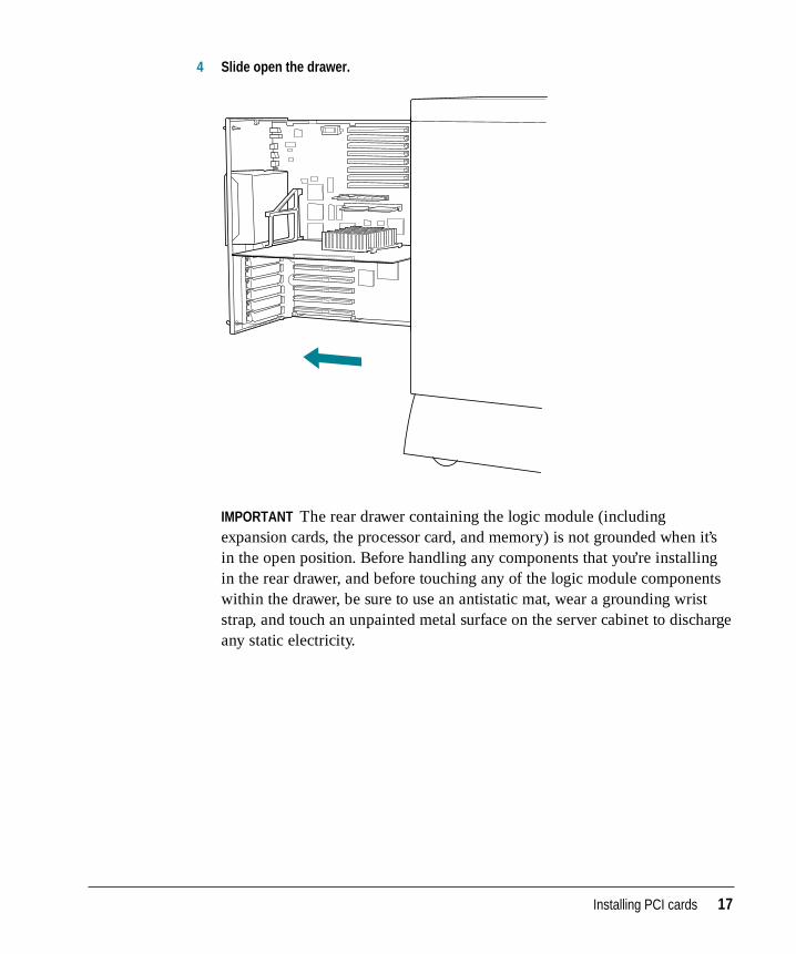
4 Slide open the drawer.
IMPORTANT The rear drawer containing the logic module (includingexpansion cards, the processor card, and memory) is not grounded when it’sin the open position. Before handling any components that you’re installingin the rear drawer, and before touching any of the logic module componentswithin the drawer, be sure to use an antistatic mat, wear a grounding wriststrap, and touch an unpainted metal surface on the server cabinet to dischargeany static electricity.
12 Chapter 2 / Installing Internal Server Components
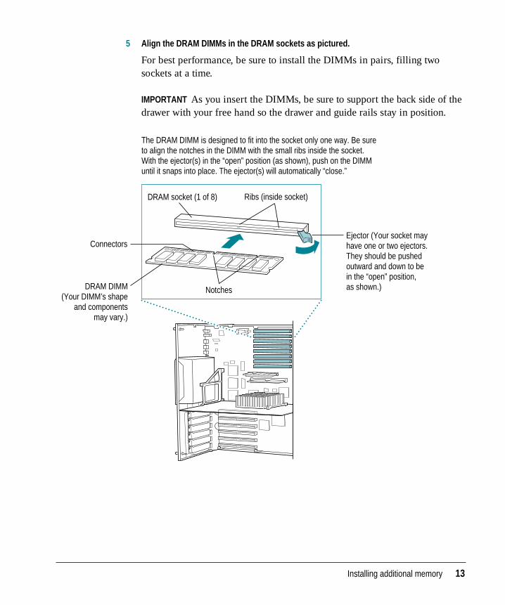
5 Align the DRAM DIMMs in the DRAM sockets as pictured.
For best performance, be sure to install the DIMMs in pairs, filling twosockets at a time.
IMPORTANT As you insert the DIMMs, be sure to support the back side of thedrawer with your free hand so the drawer and guide rails stay in position.
DRAM DIMM (Your DIMM’s shape
and components may vary.)
Connectors
Notches
DRAM socket (1 of 8) Ribs (inside socket)
Ejector (Your socket may have one or two ejectors. They should be pushed outward and down to be in the “open” position, as shown.)
The DRAM DIMM is designed to fit into the socket only one way. Be sure to align the notches in the DIMM with the small ribs inside the socket. With the ejector(s) in the “open” position (as shown), push on the DIMM until it snaps into place. The ejector(s) will automatically “close.”
Installing additional memory 13
6 Firmly slide the drawer back to its closed position and tighten the thumbscrews.
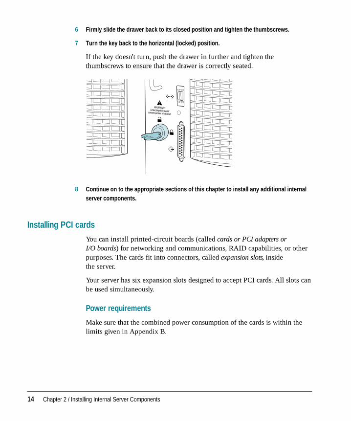
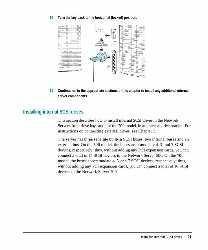
7 Turn the key back to the horizontal (locked) position.
If the key doesn’t turn, push the drawer in further and tighten thethumbscrews to ensure that the drawer is correctly seated.
8 Continue on to the appropriate sections of this chapter to install any additional internalserver components.
Installing PCI cards
You can install printed-circuit boards (called cards or PCI adapters or I/O boards) for networking and communications, RAID capabilities, or otherpurposes. The cards fit into connectors, called expansion slots, inside the server.
Your server has six expansion slots designed to accept PCI cards. All slots canbe used simultaneously.
Power requirements
Make sure that the combined power consumption of the cards is within thelimits given in Appendix B.
14 Chapter 2 / Installing Internal Server Components
Installing the card
In addition to the card, you’ll also need these items:
m a screwdriver
m a grounding wrist strap
m an antistatic mat
To install an expansion card:
1 If the server is running, shut down the operating system, turn the server off, and unplug it.
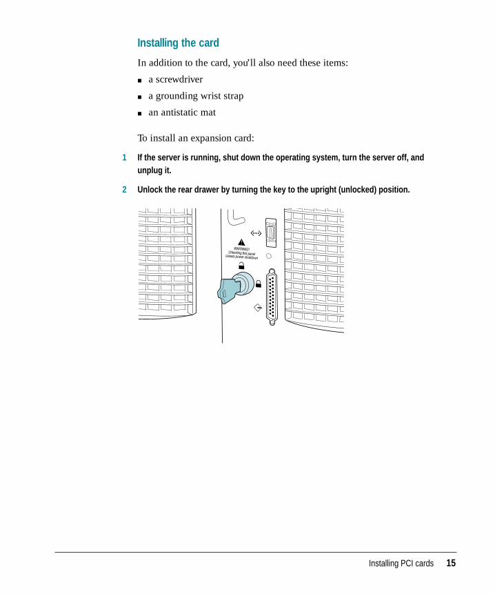
2 Unlock the rear drawer by turning the key to the upright (unlocked) position.
Installing PCI cards 15
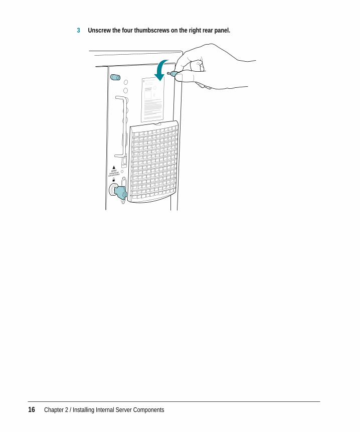
3 Unscrew the four thumbscrews on the right rear panel.
16 Chapter 2 / Installing Internal Server Components
4 Slide open the drawer.
IMPORTANT The rear drawer containing the logic module (includingexpansion cards, the processor card, and memory) is not grounded when it’sin the open position. Before handling any components that you’re installingin the rear drawer, and before touching any of the logic module componentswithin the drawer, be sure to use an antistatic mat, wear a grounding wriststrap, and touch an unpainted metal surface on the server cabinet to dischargeany static electricity.
Installing PCI cards 17
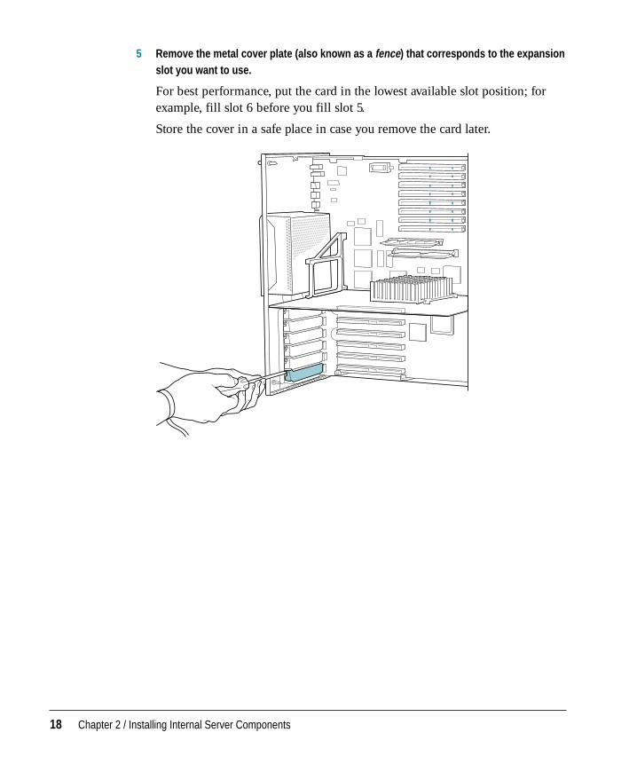
5 Remove the metal cover plate (also known as a fence) that corresponds to the expansionslot you want to use.
For best performance, put the card in the lowest available slot position; forexample, fill slot 6 before you fill slot 5.
Store the cover in a safe place in case you remove the card later.
18 Chapter 2 / Installing Internal Server Components
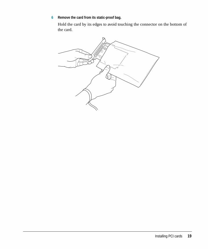
6 Remove the card from its static-proof bag.
Hold the card by its edges to avoid touching the connector on the bottom ofthe card.
Installing PCI cards 19
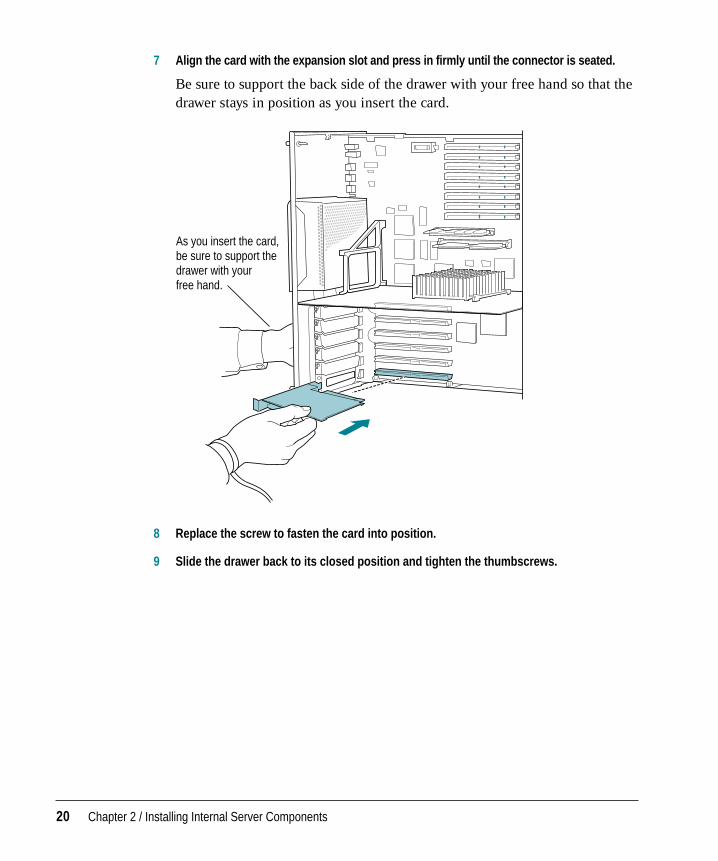
7 Align the card with the expansion slot and press in firmly until the connector is seated.
Be sure to support the back side of the drawer with your free hand so that thedrawer stays in position as you insert the card.
8 Replace the screw to fasten the card into position.
9 Slide the drawer back to its closed position and tighten the thumbscrews.
As you insert the card, be sure to support the drawer with your free hand.
20 Chapter 2 / Installing Internal Server Components
10 Turn the key back to the horizontal (locked) position.
11 Continue on to the appropriate sections of this chapter to install any additional internalserver components.
Installing internal SCSI drives
This section describes how to install internal SCSI drives in the NetworkServer’s front drive bays and, for the 700 model, in an internal drive bracket. Forinstructions on connecting external drives, see Chapter 3.
The server has three separate built-in SCSI buses: two internal buses and anexternal bus. On the 500 model, the buses accommodate 4, 3, and 7 SCSIdevices, respectively; thus, without adding any PCI expansion cards, you canconnect a total of 14 SCSI devices to the Network Server 500. On the 700model, the buses accommodate 4, 5, and 7 SCSI devices, respectively; thus,without adding any PCI expansion cards, you can connect a total of 16 SCSIdevices to the Network Server 700.
Installing internal SCSI drives 21
The internal buses handle the built-in hard disk drive, CD-ROM drive,optional DDS-2 DAT drive, and up to six additional internal SCSI drives. Theexternal bus accommodates up to seven external SCSI devices in a chain (suchas disk drives, CD-ROM drives, and tape drives). The internal buses are theSCSI-2 Fast and Wide type, which at about 20 megabytes per second (MBps)provide faster performance than the external bus, which is the SCSI-1 typeand provides speeds of approximately 5 MBps.
For best performance, balance the load between the two internal buses. Inother words, keep the number of devices on each internal bus approximatelythe same.
Setting up a SCSI device to use with your server involves
m installing any necessary device drivers
m physically connecting the device to your server
When setting up a SCSI device to use with your server, refer to the instructionsthat came with the device, as well as the instructions in this section.
Installing a device driver
A device driver is software that lets the server communicate with a particularSCSI device. Any drivers needed for a SCSI device are usually on a floppydisk that comes with the device. For information about any necessary drivers,check your AIX documentation and the information that came with thedevice. You may have to restart your server to activate the driver.
22 Chapter 2 / Installing Internal Server Components
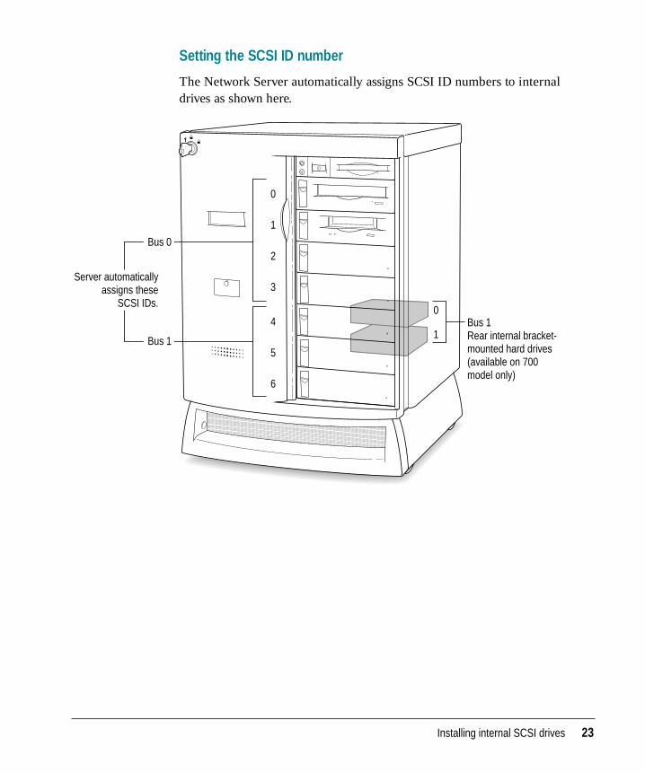
Setting the SCSI ID number
The Network Server automatically assigns SCSI ID numbers to internaldrives as shown here.
0
1
2
3
4
5
6
Bus 1 Rear internal bracket- mounted hard drives (available on 700 model only)
0
1
Bus 0
Bus 1
Server automatically assigns these
SCSI IDs.
Installing internal SCSI drives 23
Installing Network Server SCSI drives in the front drive bays
This section describes how to install the Network Server DAT-2 4mm tapedrive, CD-ROM drive, or hard drives in the front drive bays of your server.These kits, which you order from Apple for the Network Server, come withthe drive already attached to a drive tray, and with all the appropriate cables connected.
If you are installing a drive that’s not yet mounted in a drive tray, skip to thenext section, “Installing Drives Not From Kits in the Front Drive Bays.”
To install a drive kit:
1 If AIX is installed and running, shut down the operating system and turn the serverpower off.
You may be able to use procedures specific to AIX or RAID to hot-swap or adddrives while protecting your data. For details, see the information that comeswith AIX and RAID.
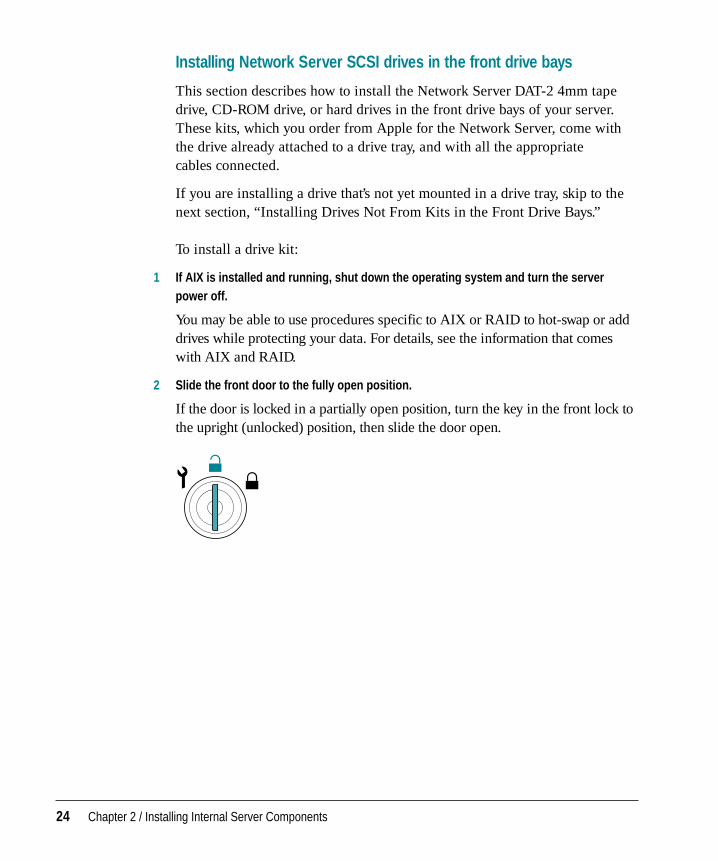
2 Slide the front door to the fully open position.
If the door is locked in a partially open position, turn the key in the front lock tothe upright (unlocked) position, then slide the door open.
24 Chapter 2 / Installing Internal Server Components
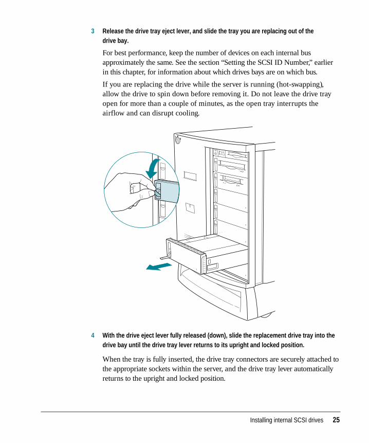
3 Release the drive tray eject lever, and slide the tray you are replacing out of the drive bay.
For best performance, keep the number of devices on each internal busapproximately the same. See the section “Setting the SCSI ID Number,” earlierin this chapter, for information about which drives bays are on which bus.
If you are replacing the drive while the server is running (hot-swapping),allow the drive to spin down before removing it. Do not leave the drive trayopen for more than a couple of minutes, as the open tray interrupts theairflow and can disrupt cooling.
4 With the drive eject lever fully released (down), slide the replacement drive tray into thedrive bay until the drive tray lever returns to its upright and locked position.
When the tray is fully inserted, the drive tray connectors are securely attached tothe appropriate sockets within the server, and the drive tray lever automaticallyreturns to the upright and locked position.
Installing internal SCSI drives 25
Installing drives not from kits in the front drive bays
This section describes how to install additional free-standing tape drives, CD-ROM drives, or hard drives in the front drive bays of your server. If youare installing a Network Server drive kit, which comes already cabled andattached to a drive tray, see the previous section, “Installing Network ServerSCSI Drives in the Front Drive Bays,” for installation instructions.
In addition to the 3.5-inch, half-height drive(s) that you’re installing, you’llalso need these items:
m a grounding wrist strap
m an antistatic mat
m a screwdriver
m four screws to attach the drive to the drive tray
m SCSI drive adapter kit (50-pin or 68-pin) for cabling the drive to the server
m if you are installing a full-height disk drive, a tape drive, or a CD-ROMdrive, a drive tray bezel (faceplate) appropriate to the device–for example,one that has an opening for inserting a tape
Note: The Network Server has built-in SCSI termination in the front drivebays, so be sure that termination is disabled on the drive(s) you are installingin the drive trays.
To install a drive:
1 If AIX is installed and running, shut down the operating system and turn the serverpower off.
You may be able to use procedures specific to AIX or RAID to hot-swap or adddrives while protecting your data. For details, see the information that comeswith AIX and RAID.
26 Chapter 2 / Installing Internal Server Components
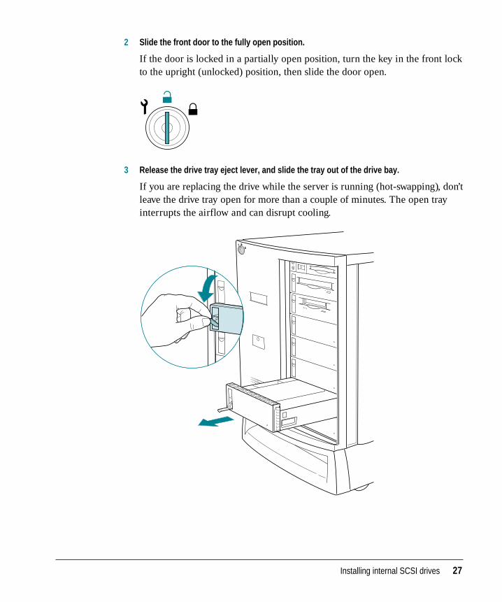
2 Slide the front door to the fully open position.
If the door is locked in a partially open position, turn the key in the front lockto the upright (unlocked) position, then slide the door open.
3 Release the drive tray eject lever, and slide the tray out of the drive bay.
If you are replacing the drive while the server is running (hot-swapping), don’tleave the drive tray open for more than a couple of minutes. The open trayinterrupts the airflow and can disrupt cooling.
Installing internal SCSI drives 27
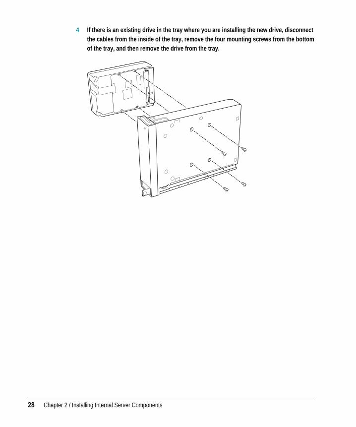
4 If there is an existing drive in the tray where you are installing the new drive, disconnectthe cables from the inside of the tray, remove the four mounting screws from the bottomof the tray, and then remove the drive from the tray.
28 Chapter 2 / Installing Internal Server Components
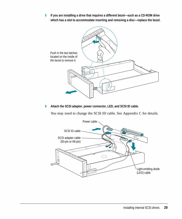
5 If you are installing a drive that requires a different bezel—such as a CD-ROM drivewhich has a slot to accommodate inserting and removing a disc—replace the bezel.
6 Attach the SCSI adapter, power connector, LED, and SCSI ID cable.
You may need to change the SCSI ID cable. See Appendix C for details.
SCSI adapter cable (50-pin or 68-pin)
Power cable
Light-emitting diode (LED) cable
SCSI ID cable
Push in the two latches located on the inside of the bezel to remove it.
Installing internal SCSI drives 29
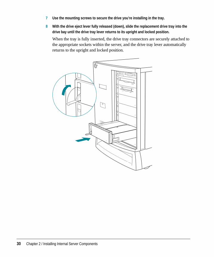
7 Use the mounting screws to secure the drive you’re installing in the tray.
8 With the drive eject lever fully released (down), slide the replacement drive tray into thedrive bay until the drive tray lever returns to its upright and locked position.
When the tray is fully inserted, the drive tray connectors are securely attached tothe appropriate sockets within the server, and the drive tray lever automaticallyreturns to the upright and locked position.
30 Chapter 2 / Installing Internal Server Components
Installing drives in the rear-mounted bracket (700 model only)
If you have the Network Server 700 model, you can install up to two drives ina drive bracket at the rear of the cabinet, behind the front drive bays. Thissection describes how to install those internal disk drives.
Note: The rear drive bracket comes as part of the hard drive kit that you orderfrom Apple.
These are the items you’ll need to install a rear-mounted drive in the server:
m a drive kit from Apple, which includes a bracket and the necessary cables(If you’re replacing an existing bracket-mounted drive, you just need a 3.5-inch half-height drive; the cables and bracket are already in place.)
m a grounding wrist strap
m an antistatic mat
m a Phillips screwdriver
If you are replacing a bracket-mounted drive with one that you purchasedfrom a supplier other than Apple, you’ll also need these items:
m a Fast and Wide drive with a 68-pin connector
m switches or jumpers as needed to set SCSI IDs for the drives you are installing
Note: The last bracket-mounted drive on the SCSI cable must havetermination enabled.
Installing internal SCSI drives 31
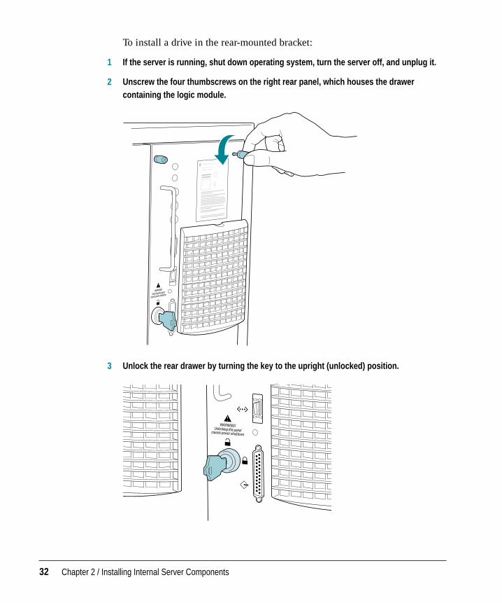
To install a drive in the rear-mounted bracket:
1 If the server is running, shut down operating system, turn the server off, and unplug it.
2 Unscrew the four thumbscrews on the right rear panel, which houses the drawercontaining the logic module.
3 Unlock the rear drawer by turning the key to the upright (unlocked) position.
32 Chapter 2 / Installing Internal Server Components

4 Slide open the drawer.
WARNING Be sure to leave the rear drawer open until you complete thedrive installation process.
Installing internal SCSI drives 33
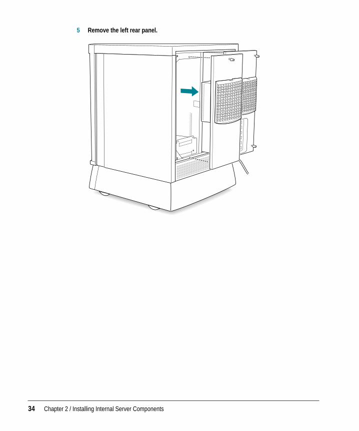
5 Remove the left rear panel.
34 Chapter 2 / Installing Internal Server Components
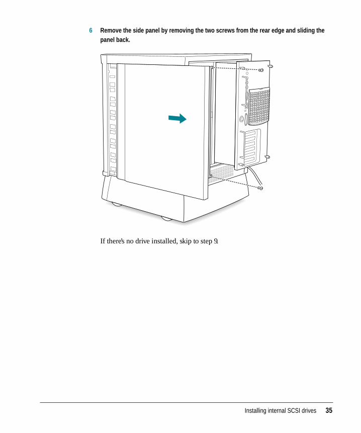
6 Remove the side panel by removing the two screws from the rear edge and sliding thepanel back.
If there’s no drive installed, skip to step 9.
Installing internal SCSI drives 35
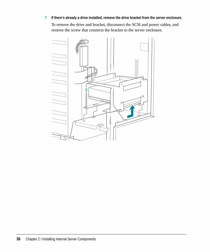
7 If there’s already a drive installed, remove the drive bracket from the server enclosure.
To remove the drive and bracket, disconnect the SCSI and power cables, andremove the screw that connects the bracket to the server enclosure.
36 Chapter 2 / Installing Internal Server Components
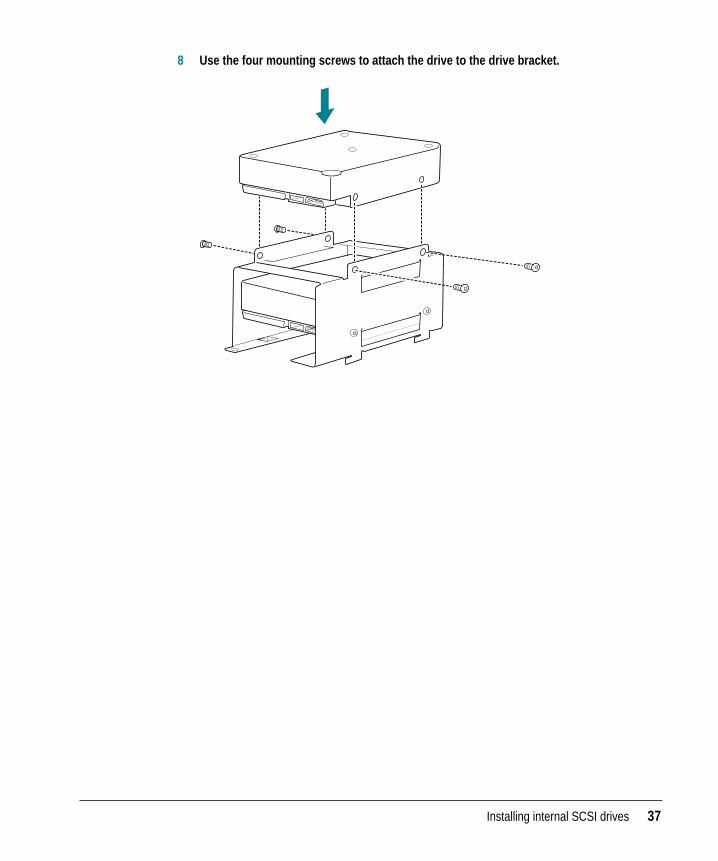
8 Use the four mounting screws to attach the drive to the drive bracket.
Installing internal SCSI drives 37
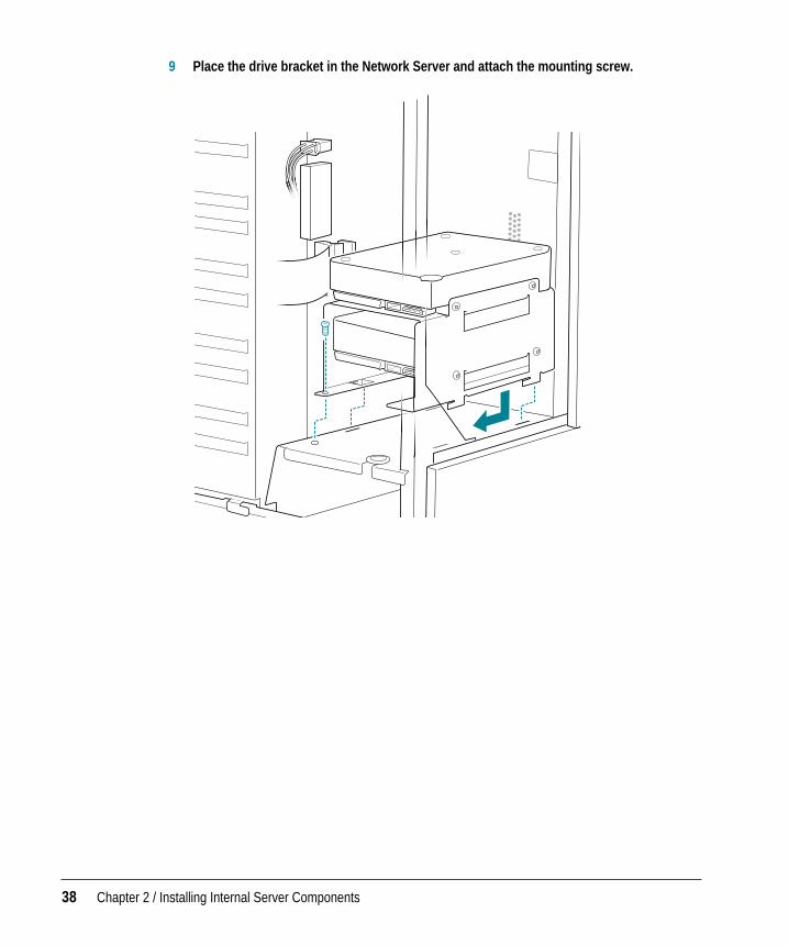
9 Place the drive bracket in the Network Server and attach the mounting screw.
38 Chapter 2 / Installing Internal Server Components
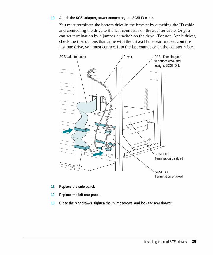
10 Attach the SCSI adapter, power connector, and SCSI ID cable.
You must terminate the bottom drive in the bracket by attaching the ID cableand connecting the drive to the last connector on the adapter cable. Or youcan set termination by a jumper or switch on the drive. (For non-Apple drives,check the instructions that came with the drive.) If the rear bracket containsjust one drive, you must connect it to the last connector on the adapter cable.
11 Replace the side panel.
12 Replace the left rear panel.
13 Close the rear drawer, tighten the thumbscrews, and lock the rear drawer.
Power SCSI ID cable goes to bottom drive and assigns SCSI ID 1.
SCSI ID 0 Termination disabled
SCSI ID 1 Termination enabled
SCSI adapter cable
Installing internal SCSI drives 39
Preparing a hard disk for use
For information on configuring a disk for use with the operating system, seethe chapter “Managing File Storage With the Disk Management Utility” inUsing AIX, AppleTalk Services, and Mac OS Utilities on the Network Server.
Verifying internal SCSI devices
After you install one or more drives and turn on your server, you can useOpen Firmware commands to display information regarding which SCSIdevices are currently recognized by the server.
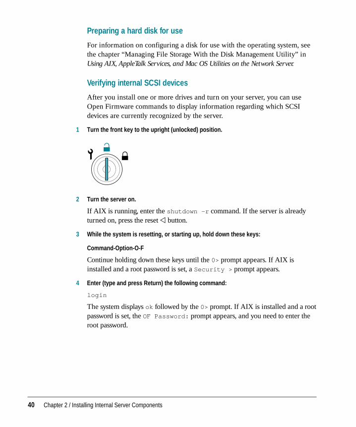
1 Turn the front key to the upright (unlocked) position.
2 Turn the server on.
If AIX is running, enter the shutdown -r command. If the server is alreadyturned on, press the reset P button.
3 While the system is resetting, or starting up, hold down these keys:
Command-Option-O-F
Continue holding down these keys until the 0> prompt appears. If AIX isinstalled and a root password is set, a Security > prompt appears.
4 Enter (type and press Return) the following command:
login
The system displays ok followed by the 0> prompt. If AIX is installed and a rootpassword is set, the OF Password: prompt appears, and you need to enter theroot password.
40 Chapter 2 / Installing Internal Server Components
5 Enter the following command:
probe-scsi1
This command displays the devices on the first internal bus. To display SCSI IDinformation for the devices on the second internal bus, use this command:
probe-scsi2
The system displays SCSI ID information similar to this:
Replacing or adding a power supply (700 model only)
The Network Server 500 comes equipped with a single fixed power supply,while the Network Server 700 model can accommodate two power supplies.To replace a Network Server 500 power supply, contact your service provider.
To replace a Network Server 700 power supply or to add a second power supply:
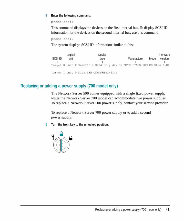
1 Turn the front key to the unlocked position.
Replacing or adding a power supply (700 model only) 41
Target 0 Unit 0 Removable Read Only device MATSHITACD-ROM CR8005A 4.01 Target 1 Unit 0 Disk IBM OEMDFHSS2W4141
SCSI IDLogical
unitDevice
type ModelFirmwareversionManufacturer
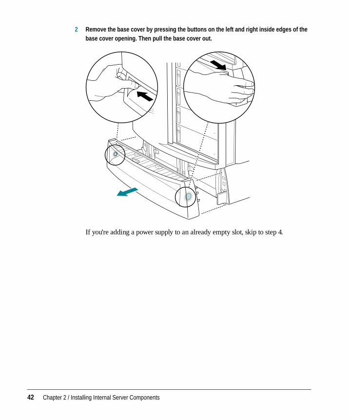
2 Remove the base cover by pressing the buttons on the left and right inside edges of thebase cover opening. Then pull the base cover out.
If you’re adding a power supply to an already empty slot, skip to step 4.
42 Chapter 2 / Installing Internal Server Components
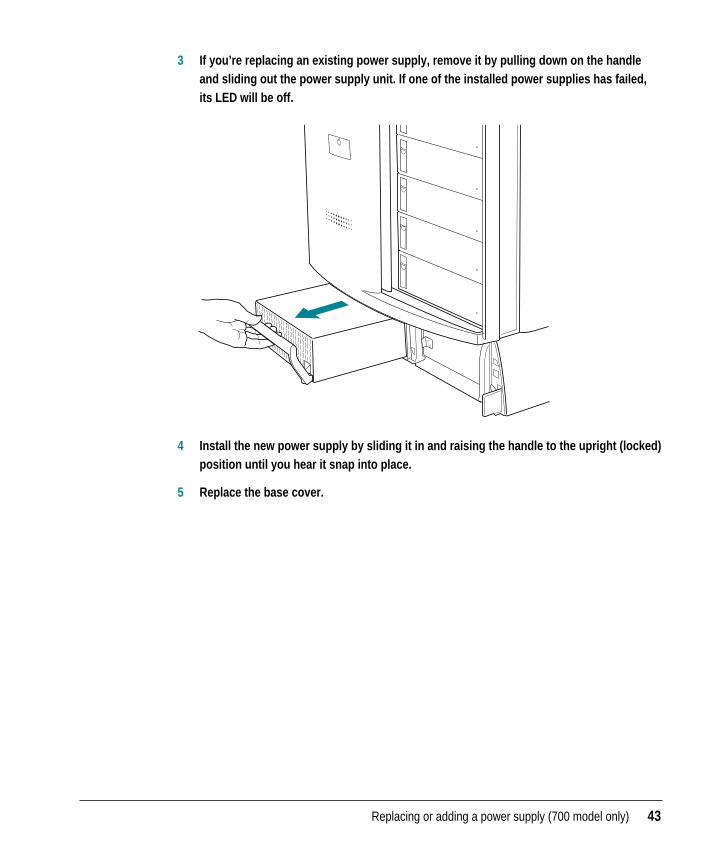
3 If you’re replacing an existing power supply, remove it by pulling down on the handleand sliding out the power supply unit. If one of the installed power supplies has failed,its LED will be off.
4 Install the new power supply by sliding it in and raising the handle to the upright (locked)position until you hear it snap into place.
5 Replace the base cover.
Replacing or adding a power supply (700 model only) 43
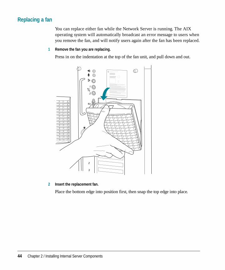
Replacing a fan
You can replace either fan while the Network Server is running. The AIXoperating system will automatically broadcast an error message to users whenyou remove the fan, and will notify users again after the fan has been replaced.
1 Remove the fan you are replacing.
Press in on the indentation at the top of the fan unit, and pull down and out.
2 Insert the replacement fan.
Place the bottom edge into position first, then snap the top edge into place.
44 Chapter 2 / Installing Internal Server Components
After you’ve installed any internal components as described in the previouschapter, read the information in this chapter about physically protecting yourserver from unauthorized access. This chapter also covers installing theNetwork Server in a rack, connecting external components such as diskdrives, and connecting a monitor or serial terminal, keyboard, and mouse.
After you’ve connected the external devices, the next step is to connect theserver to the network, as described in Chapter 4.
3 Setting Up Your Server and Connecting External Devices
Important site considerations
When determining the location and placement of your Network Server, besure that the environmental conditions are appropriate, electrical service isadequate, and the server is positioned safely.
Electrical requirements
Check the information on the server nameplate and for the other equipmentthat share the same circuit. Based on the electrical service to your site, youmay decide to connect each server to its own branch circuit. Applerecommends that you use an external AC surge protector to minimizepossible degradation of Network Server performance due to powerline surges.
The Network Server uses a grounded plug. For safe operation, be sure toconnect the server to a grounded outlet. Be sure to leave one end of the powercord free in case you need to unplug your server. If you connect to anextension cord or outlet strip, be sure those components are grounded too.
Temperature and airflow
The maximum ambient operating temperature for the server is 40° C (104° F).If you install the server in a closed or multi-unit rack assembly, thatenvironment may have a temperature greater than the ambient roomtemperature. Be sure that there is adequate cooling and airflow to maintainthe temperature within a safe operating level.
In order to ensure adequate airflow around the server, provide one inch ofclearance on the sides, four inches on the back, and leave the frontunobstructed. Other than the few minutes that might be required to swap adrive, don’t operate the server with any of the front drive trays open. Drivetrays must be closed in order to provide optimal cooling.
46 Chapter 3 / Setting Up Your Server and Connecting External Devices
Security and safety issues
The Network Server lets you concentrate valuable or sensitive information onone system that can be physically isolated and more carefully monitored thanwould be possible if that information were stored on personal computers.Before you set up the server, you may want to consider three measures thatyou can take to secure the hardware components: physically isolating thesystem, using a locking cable to secure the system, and using the server’slocks on the front and rear panels.
Physically isolating the system
It is important to note that even if software security features (such aspassword protection or locking screen savers) are in use on the server, it isstill possible to disconnect peripheral devices, such as hard disks that maycontain confidential information. There is no better way to protect hardwareand components than by physically isolating the server–locking it either in awell-ventilated cabinet or in a room with controlled access. Depending onyour security needs, the nature of the data stored on the server may warrantthe effort.
Using a locking cable
As an alternative to isolating the system completely in an area of controlledaccess, you can purchase a locking cable and attach it to your server. Theback panel has a built-in security slot for a locking cable. Follow theinstructions supplied with the locking cable to attach it to your server.
By itself, a locking cable cannot prevent unauthorized use of the server, but itcan prevent the server (and its peripheral devices if they are also secured bylocking cables) from being removed.
WARNING The Network Server contains components and circuitry thatoperate at high energy levels. Lock the server cabinet and keep theserver in a locked area in order to prevent access by people unfamiliarwith the safe operation and use of the equipment.
Security and safety issues 47

In combination with the locks on the front and rear panels, a locking cableensures that the system is secure physically and that only the person with thekey can operate it locally.
Security lock port
48 Chapter 3 / Setting Up Your Server and Connecting External Devices
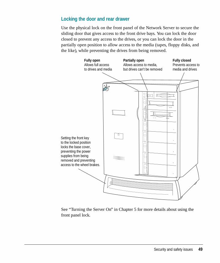
Locking the door and rear drawer
Use the physical lock on the front panel of the Network Server to secure thesliding door that gives access to the front drive bays. You can lock the doorclosed to prevent any access to the drives, or you can lock the door in thepartially open position to allow access to the media (tapes, floppy disks, andthe like), while preventing the drives from being removed.
See “Turning the Server On” in Chapter 5 for more details about using thefront panel lock.
Fully closed Prevents access to media and drives
Partially open Allows access to media, but drives can’t be removed
Fully open Allows full access to drives and media
Setting the front key to the locked position locks the base cover, preventing the power supplies from being removed and preventing access to the wheel brakes.
Security and safety issues 49
The front and rear locks use matching keys, so the same key that works thefront lock also fits the lock for the rear panel drawer. This rear drawer mustbe locked in order for you to turn on server power. Locking the rear drawerprevents access to high-energy areas and also protects the cards, memorycomponents, and other expensive internal parts.
After locking the server, be sure to remove the keys and store them in a safe place.
Replacing lost keys
The Network Server comes with three keys. Because lost keys are difficult toreplace, you may want to make duplicates of your keys. If you lose all threekeys, the following solutions are available:
m Contact a locksmith. Most locksmiths can create a new set of keys directlyfrom the key lock.
m Contact your Apple-authorized service provider for assistance. The serviceprovider can order additional keys from the lock manufacturer. (The lockmanufacturer will accept calls only from Apple-authorized serviceproviders.)
m As an alternative to ordering new keys, the service provider can replace thefront panel lock and rear drawer lock on your Network Server and providenew keys.
50 Chapter 3 / Setting Up Your Server and Connecting External Devices
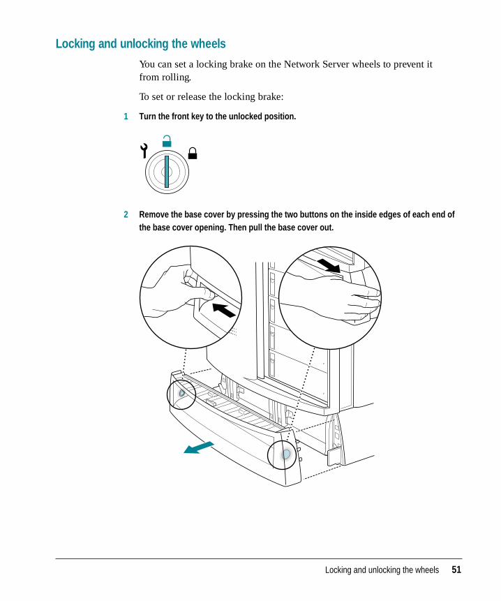
Locking and unlocking the wheels
You can set a locking brake on the Network Server wheels to prevent it from rolling.
To set or release the locking brake:
1 Turn the front key to the unlocked position.
2 Remove the base cover by pressing the two buttons on the inside edges of each end ofthe base cover opening. Then pull the base cover out.
Locking and unlocking the wheels 51
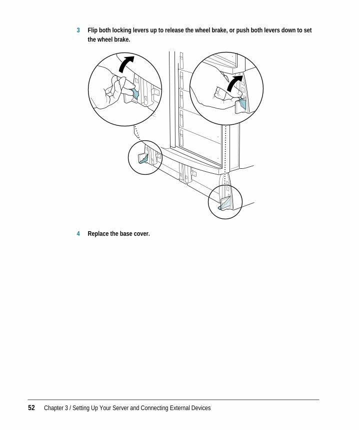
3 Flip both locking levers up to release the wheel brake, or push both levers down to setthe wheel brake.
4 Replace the base cover.
52 Chapter 3 / Setting Up Your Server and Connecting External Devices
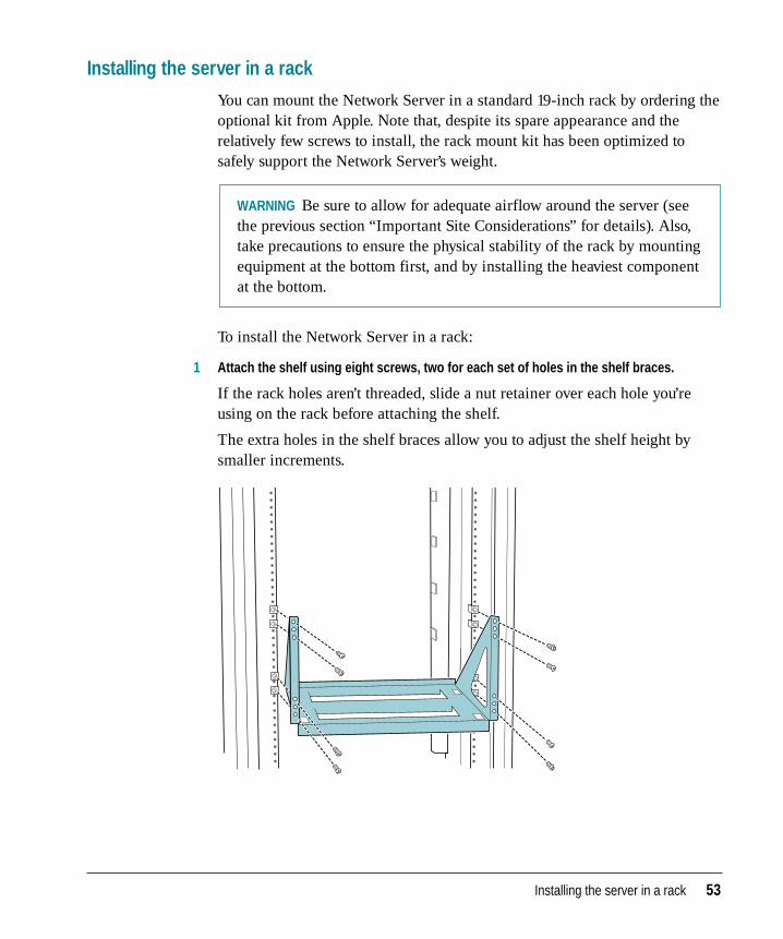
Installing the server in a rack
You can mount the Network Server in a standard 19-inch rack by ordering theoptional kit from Apple. Note that, despite its spare appearance and therelatively few screws to install, the rack mount kit has been optimized tosafely support the Network Server’s weight.
To install the Network Server in a rack:
1 Attach the shelf using eight screws, two for each set of holes in the shelf braces.
If the rack holes aren’t threaded, slide a nut retainer over each hole you’reusing on the rack before attaching the shelf.
The extra holes in the shelf braces allow you to adjust the shelf height bysmaller increments.
WARNING Be sure to allow for adequate airflow around the server (seethe previous section “Important Site Considerations” for details). Also,take precautions to ensure the physical stability of the rack by mountingequipment at the bottom first, and by installing the heaviest componentat the bottom.
Installing the server in a rack 53
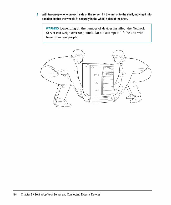
2 With two people, one on each side of the server, lift the unit onto the shelf, moving it intoposition so that the wheels fit securely in the wheel holes of the shelf.
WARNING Depending on the number of devices installed, the NetworkServer can weigh over 90 pounds. Do not attempt to lift the unit withfewer than two people.
54 Chapter 3 / Setting Up Your Server and Connecting External Devices
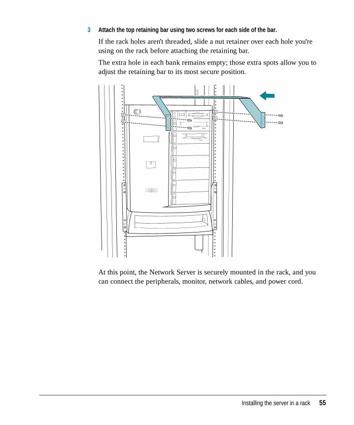
3 Attach the top retaining bar using two screws for each side of the bar.
If the rack holes aren’t threaded, slide a nut retainer over each hole you’reusing on the rack before attaching the retaining bar.
The extra hole in each bank remains empty; those extra spots allow you toadjust the retaining bar to its most secure position.
At this point, the Network Server is securely mounted in the rack, and youcan connect the peripherals, monitor, network cables, and power cord.
Installing the server in a rack 55
Adding disk drives and other external SCSI devices
This section describes how to connect external SCSI devices to the NetworkServer. See Chapter 2 for information on installing internal SCSI devices.
The server has three separate built-in SCSI buses: two internal buses and anexternal bus. The external bus accommodates up to seven external SCSIdevices in a chain (such as hard disks, CD-ROM drives, and tape drives) andis the SCSI-1 type, which provides speeds of approximately 5 megabytes persecond (MBps).
Setting up a SCSI device to use with your server involves
m installing any necessary device drivers
m setting the device’s SCSI ID number
m physically connecting the device to your server
When setting up a SCSI device to use with your server, refer to theinstructions that came with the device, as well as the instructions in this section.
Installing a device driver
A device driver is software that lets the server communicate with a particularSCSI device. Any drivers needed for a SCSI device are usually on a floppydisk that comes with the device. For information about any necessary drivers,check your AIX documentation and the information that came with thedevice. You may have to restart your server to activate the driver.
Setting the SCSI ID number
As discussed previously, the Network Server contains three built-in SCSIbuses: two internal buses and an external bus. The Network Serverautomatically assigns SCSI ID numbers to internal drives, as described inChapter 2.
This section tells you how to set the ID number for an external Apple SCSIdevice. When setting a SCSI ID for another manufacturer’s device, refer to theinstructions included with that device.
56 Chapter 3 / Setting Up Your Server and Connecting External Devices
To set the SCSI ID number for an Apple SCSI device that you are attaching externally:
1 Make sure the device is switched off.
2 Choose a number that doesn’t duplicate the ID of any other external SCSI deviceconnected to your server.
You can assign any number between 0 and 6, provided that each externalSCSI device is uniquely identified.
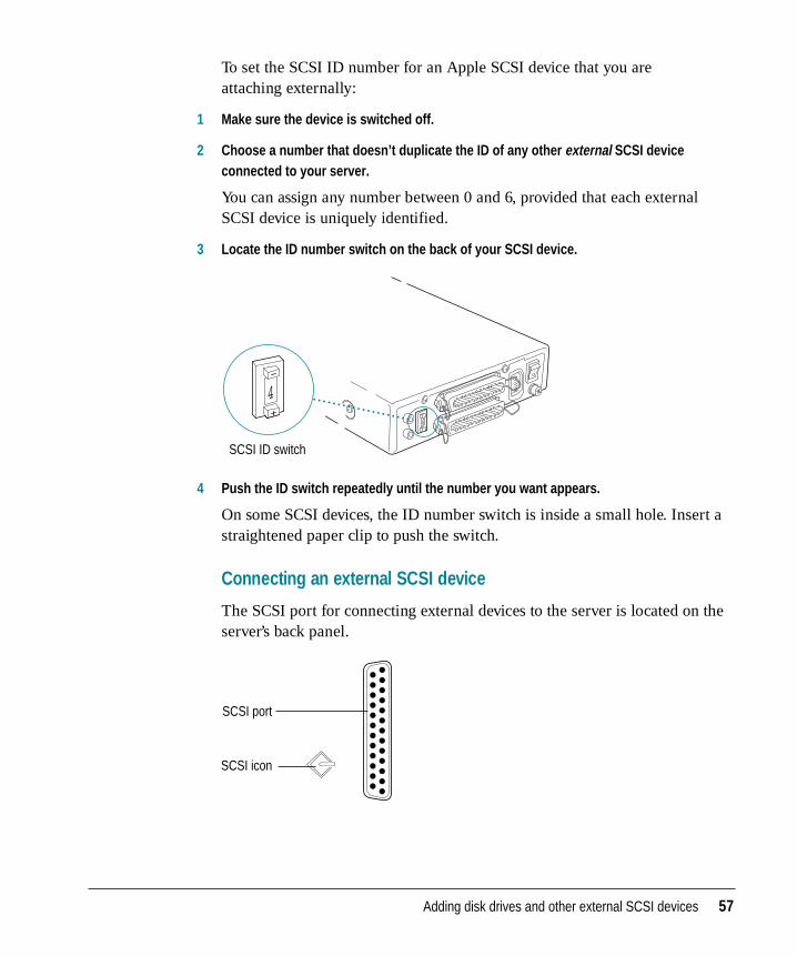
3 Locate the ID number switch on the back of your SCSI device.
4 Push the ID switch repeatedly until the number you want appears.
On some SCSI devices, the ID number switch is inside a small hole. Insert astraightened paper clip to push the switch.
Connecting an external SCSI device
The SCSI port for connecting external devices to the server is located on theserver’s back panel.
SCSI port
SCSI icon
SCSI ID switch
4
Adding disk drives and other external SCSI devices 57
To connect a SCSI device to your server:
1 Turn off your server.
2 Make sure the SCSI device is switched off.
3 Make sure the device has a unique ID number between 0 and 6.
See the earlier section “Setting the SCSI ID Number” for details.
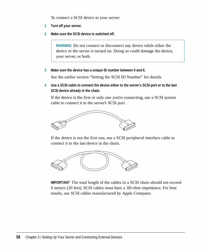
4 Use a SCSI cable to connect the device either to the server’s SCSI port or to the lastSCSI device already in the chain.
If the device is the first or only one you’re connecting, use a SCSI systemcable to connect it to the server’s SCSI port.
If the device is not the first one, use a SCSI peripheral interface cable toconnect it to the last device in the chain.
IMPORTANT The total length of the cables in a SCSI chain should not exceed 6 meters (20 feet). SCSI cables must have a 110-ohm impedance. For bestresults, use SCSI cables manufactured by Apple Computer.
WARNING Do not connect or disconnect any device while either thedevice or the server is turned on. Doing so could damage the device,your server, or both.
58 Chapter 3 / Setting Up Your Server and Connecting External Devices
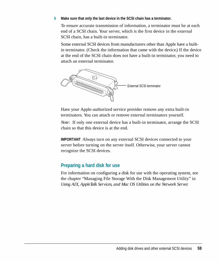
5 Make sure that only the last device in the SCSI chain has a terminator.
To ensure accurate transmission of information, a terminator must be at eachend of a SCSI chain. Your server, which is the first device in the externalSCSI chain, has a built-in terminator.
Some external SCSI devices from manufacturers other than Apple have a built-in terminator. (Check the information that came with the device.) If the deviceat the end of the SCSI chain does not have a built-in terminator, you need toattach an external terminator.
Have your Apple-authorized service provider remove any extra built-interminators. You can attach or remove external terminators yourself.
Note: If only one external device has a built-in terminator, arrange the SCSIchain so that this device is at the end.
IMPORTANT Always turn on any external SCSI devices connected to yourserver before turning on the server itself. Otherwise, your server cannotrecognize the SCSI devices.
Preparing a hard disk for useFor information on configuring a disk for use with the operating system, seethe chapter “Managing File Storage With the Disk Management Utility” inUsing AIX, AppleTalk Services, and Mac OS Utilities on the Network Server.
External SCSI terminator
Adding disk drives and other external SCSI devices 59

Verifying external SCSI devices
After you install one or more drives and turn on your system, you can useOpen Firmware commands to display information regarding which SCSIdevices are currently recognized by the server.
1 Turn the front key to the upright (unlocked) position.
2 Turn the server on.
If AIX is running, enter the shutdown -r command. If the server is alreadyturned on, press the reset P button.
3 While the system is resetting, or starting up, hold down these keys:
Command-Option-O-F
Continue holding down these keys until the 0> prompt appears. If AIX isinstalled and a root password is set, a Security > prompt appears.
4 Enter (type and press Return) the following command:
login
The system displays ok followed by the 0> prompt. If AIX is installed and a rootpassword is set, the OF Password: prompt appears, and you need to enter theroot password.
60 Chapter 3 / Setting Up Your Server and Connecting External Devices
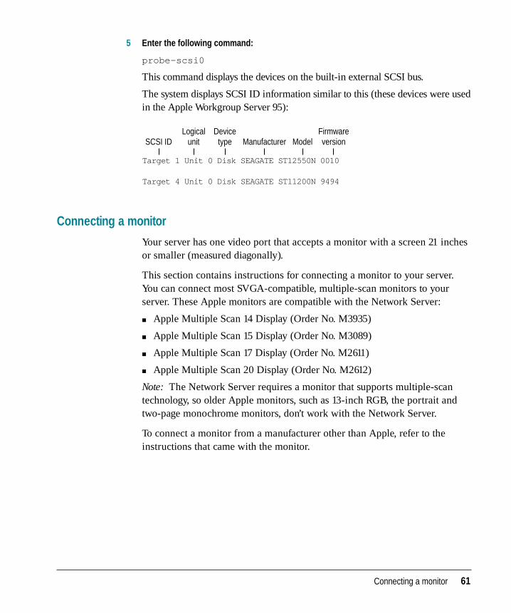
5 Enter the following command:
probe-scsi0
This command displays the devices on the built-in external SCSI bus.
The system displays SCSI ID information similar to this (these devices were usedin the Apple Workgroup Server 95):
Connecting a monitor
Your server has one video port that accepts a monitor with a screen 21 inchesor smaller (measured diagonally).
This section contains instructions for connecting a monitor to your server.You can connect most SVGA-compatible, multiple-scan monitors to yourserver. These Apple monitors are compatible with the Network Server:
m Apple Multiple Scan 14 Display (Order No. M3935)
m Apple Multiple Scan 15 Display (Order No. M3089)
m Apple Multiple Scan 17 Display (Order No. M2611)
m Apple Multiple Scan 20 Display (Order No. M2612)
Note: The Network Server requires a monitor that supports multiple-scantechnology, so older Apple monitors, such as 13-inch RGB, the portrait andtwo-page monochrome monitors, don’t work with the Network Server.
To connect a monitor from a manufacturer other than Apple, refer to theinstructions that came with the monitor.
Connecting a monitor 61
Target 1 Unit 0 Disk SEAGATE ST12550N 0010 Target 4 Unit 0 Disk SEAGATE ST11200N 9494
SCSI IDLogical
unitDevice
type ModelFirmwareversionManufacturer
Connecting the monitor’s power cordMonitors have two cords you connect—a power cord and a monitor cable.
To connect the monitor’s power cord:
1 Place the monitor where you will be using it.
Keep in mind these considerations:
m Make sure that the ventilation openings on the server and the monitors areclear and unobstructed.
m Make sure the top of the screen is slightly below eye level when you’resitting at the keyboard.
m Position the monitor to minimize glare and reflections on the screen fromoverhead lights and windows.
m Consult “Arranging Your Office” in Appendix A for suggestions aboutlocating your server equipment.
2 Check that the server and all connected devices are turned off.
3 Connect the monitor’s power cord to the monitor.
On some monitors, the cord is already attached.
4 Plug in the monitor’s power cord.
Plug the power cord into a grounded electrical outlet.
Connecting the monitor cable
After you plug in the monitor’s power cord, connect the monitor cable to theserver’s monitor port.
Note: You may need to extend the length of your monitor cable, for example,if you installed your Network Server in a rack so that the distance betweenthe server and the monitor is greater than the reach of the standard cable. Be sure to use only an approved video extender cable rated for use withmultiple-scan monitors. Do not use CPU-to-video monitor cables that mayhave been supplied with older RGB displays; not all the pins are “wiredthrough” on those cables.
62 Chapter 3 / Setting Up Your Server and Connecting External Devices
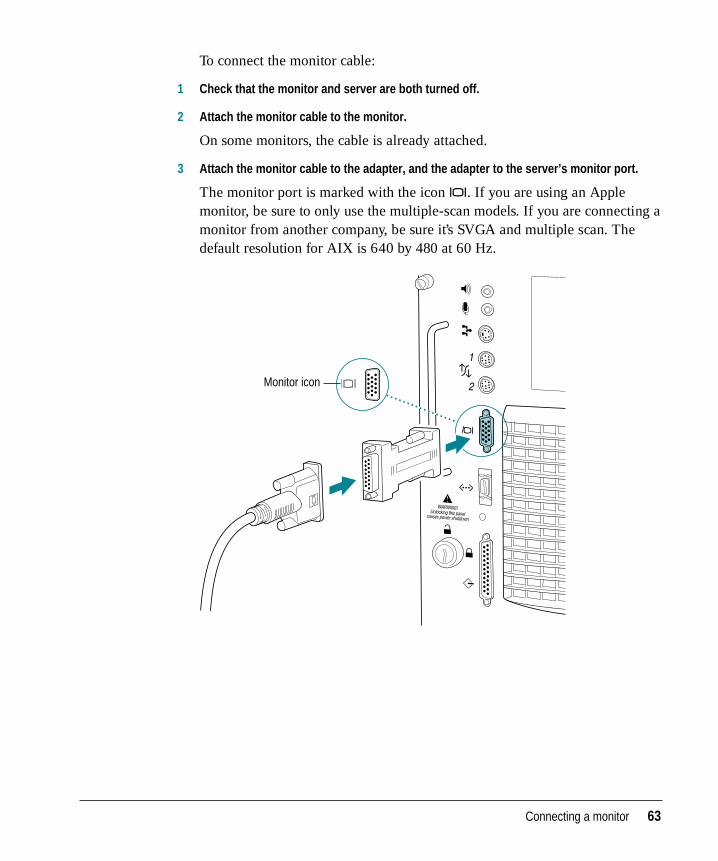
To connect the monitor cable:
1 Check that the monitor and server are both turned off.
2 Attach the monitor cable to the monitor.
On some monitors, the cable is already attached.
3 Attach the monitor cable to the adapter, and the adapter to the server’s monitor port.
The monitor port is marked with the icon ™. If you are using an Applemonitor, be sure to only use the multiple-scan models. If you are connecting amonitor from another company, be sure it’s SVGA and multiple scan. Thedefault resolution for AIX is 640 by 480 at 60 Hz.
Monitor icon
Connecting a monitor 63
Connecting a system console
To connect the Network Server to a Macintosh or PC as a system console, youneed these items:
m an 8-pin DIN to 8-pin DIN serial cable (number M0197)
m a terminal emulation program, such as MacTerminal 3.0 or greater, or someother suitable terminal emulation program running on a computer thatyou’re using as the terminal
1 Configure the terminal emulation software.
Set the terminal interface protocols to 8 bit, no parity, and stop bits equal toone. Set any baud rate between 9600 and 57600.
2 Connect one end of the serial cable to serial connection port 2 on the server, and theother end to the modem port on the computer that you’re using as the terminal.
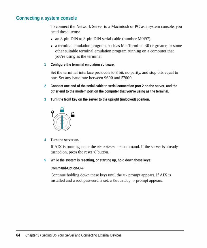
3 Turn the front key on the server to the upright (unlocked) position.
4 Turn the server on.
If AIX is running, enter the shutdown -r command. If the server is alreadyturned on, press the reset P button.
5 While the system is resetting, or starting up, hold down these keys:
Command-Option-O-F
Continue holding down these keys until the 0> prompt appears. If AIX isinstalled and a root password is set, a Security > prompt appears.
64 Chapter 3 / Setting Up Your Server and Connecting External Devices
6 Enter (type and press Return) the following command:
login
The system displays ok followed by the 0> prompt. If AIX is installed and a rootpassword is set, the OF Password: prompt appears, and you need to enter theroot password.
7 Use the setenv command to specify serial port 2 for video output and keyboard input.
Use the same baud rate as you specified in your terminal emulation programsetup. These commands assume a baud rate of 9600:
setenv input-device ttya:9600
setenv output-device ttya:9600
To reset the input to the ADB port and output to the monitor port, enter these commands:
setenv input-device kbd
setenv output-device screen
Connecting the mouse and keyboard
In order to run your Network Server with AIX and a monitor, you need toconnect an ADB-compatible extended keyboard. You have a choice of severalkeyboards for your server. You may also choose from among several mouseoptions. AIX supports both a one-button mouse and a three-button mouse. Ifyou frequently work at the server using graphical displays, you may find thata three-button mouse makes it easier to use AIX.
Connecting the mouse and keyboard 65
Regardless of which type of keyboard or mouse you use, you connect eachone in the same way:
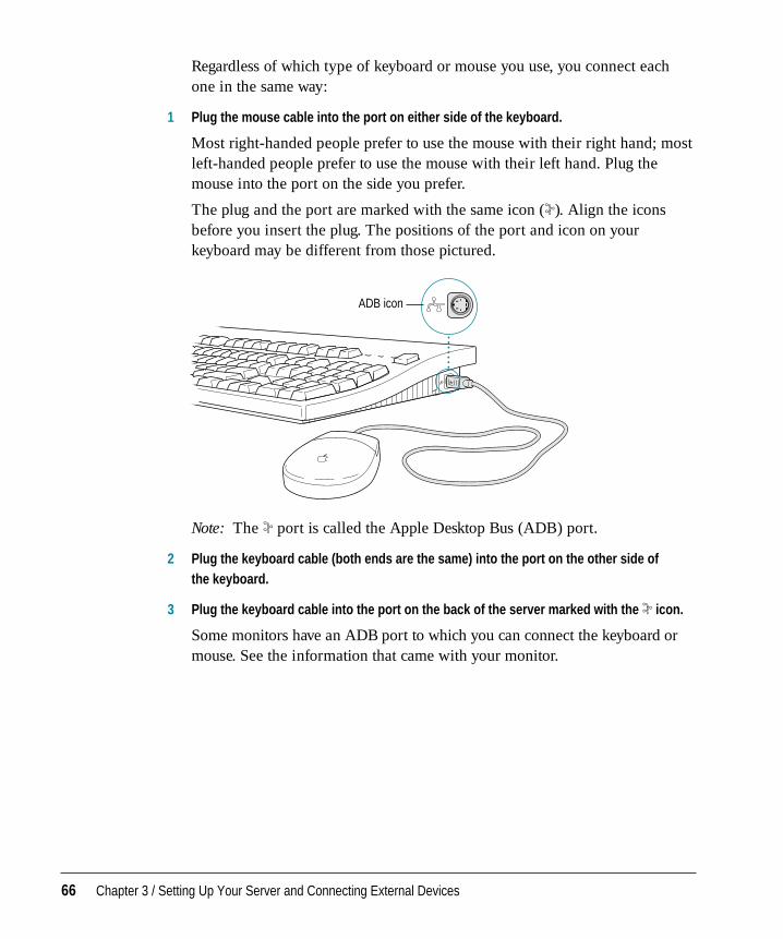
1 Plug the mouse cable into the port on either side of the keyboard.
Most right-handed people prefer to use the mouse with their right hand; mostleft-handed people prefer to use the mouse with their left hand. Plug themouse into the port on the side you prefer.
The plug and the port are marked with the same icon (◊). Align the iconsbefore you insert the plug. The positions of the port and icon on yourkeyboard may be different from those pictured.
Note: The ◊ port is called the Apple Desktop Bus (ADB) port.
2 Plug the keyboard cable (both ends are the same) into the port on the other side of the keyboard.
3 Plug the keyboard cable into the port on the back of the server marked with the ◊ icon.
Some monitors have an ADB port to which you can connect the keyboard ormouse. See the information that came with your monitor.
ADB icon
66 Chapter 3 / Setting Up Your Server and Connecting External Devices
This chapter describes how to connect your server to the network through thebuilt-in Ethernet interface as well as through additional network interfacecards that you may choose to install to expand the Network Server’scapabilities. It gives specific instructions for connecting with the Apple PCIEthernet Card and the Apple PCI Ethernet 100BASE-TX Card. After youconnect your server to the network, see Using AIX, AppleTalk Services, and Mac OS Utilities on the Network Server for information on configuring thenetwork.
Note: With the appropriate communications card and software, you can alsoconnect your server to other network types, such as a token ring or an FDDInetwork. See your Apple-authorized dealer for more information.
Installing a networking card
Your server has six expansion slots designed to accept PCI cards. All slotscan be used simultaneously. See “Installing PCI Cards” in Chapter 2 forinstructions on how to install networking cards in your system. After the card is installed, follow the steps in this chapter to connect the server to the network.
4 Connecting Your Server to the Network
Connecting the built-in Ethernet (AAUI) port to the network
The Network Server contains built-in hardware for connecting to a 10 megabits per second (Mbps) Ethernet network. Connecting to the networkrequires a piece of hardware called a transceiver or media adapter. You mustpurchase this adapter separately for the type of network cables that yournetwork uses.
The built-in (on-board) Ethernet capabilities of your Network Server allowyou to connect to any standard Ethernet network using thin coaxial (or“coax”), twisted-pair, or thick coaxial cables. You can also use fiber-opticmedia or other standard Ethernet cables.
To connect the server to an Ethernet network, you need one of these Ethernetmedia adapters for the type of cables that your network uses:
m Apple Ethernet Thin Coax Transceiver
m Apple Ethernet Twisted-Pair Transceiver
m Apple Ethernet AUI Adapter and AUI media adapter appropriate for yournetwork cable
See your Apple-authorized dealer for more information on Apple Ethernetmedia adapters for your Network Server.
68 Chapter 4 / Connecting Your Server to the Network
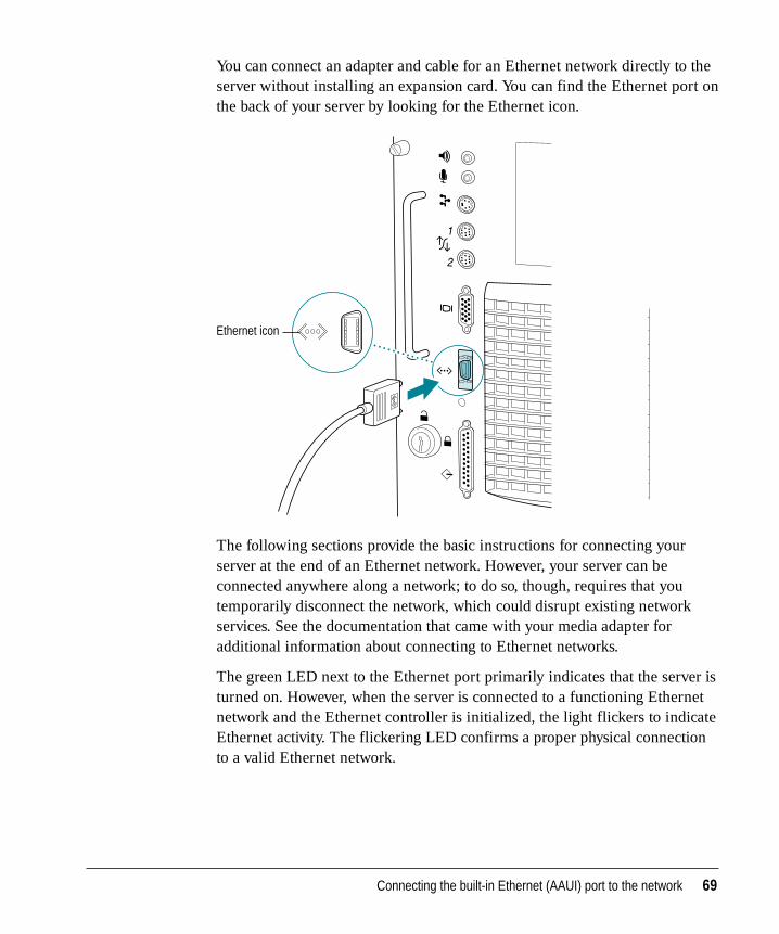
You can connect an adapter and cable for an Ethernet network directly to theserver without installing an expansion card. You can find the Ethernet port onthe back of your server by looking for the Ethernet icon.
The following sections provide the basic instructions for connecting yourserver at the end of an Ethernet network. However, your server can beconnected anywhere along a network; to do so, though, requires that youtemporarily disconnect the network, which could disrupt existing networkservices. See the documentation that came with your media adapter foradditional information about connecting to Ethernet networks.
The green LED next to the Ethernet port primarily indicates that the server isturned on. However, when the server is connected to a functioning Ethernetnetwork and the Ethernet controller is initialized, the light flickers to indicateEthernet activity. The flickering LED confirms a proper physical connectionto a valid Ethernet network.
Ethernet icon
Connecting the built-in Ethernet (AAUI) port to the network 69
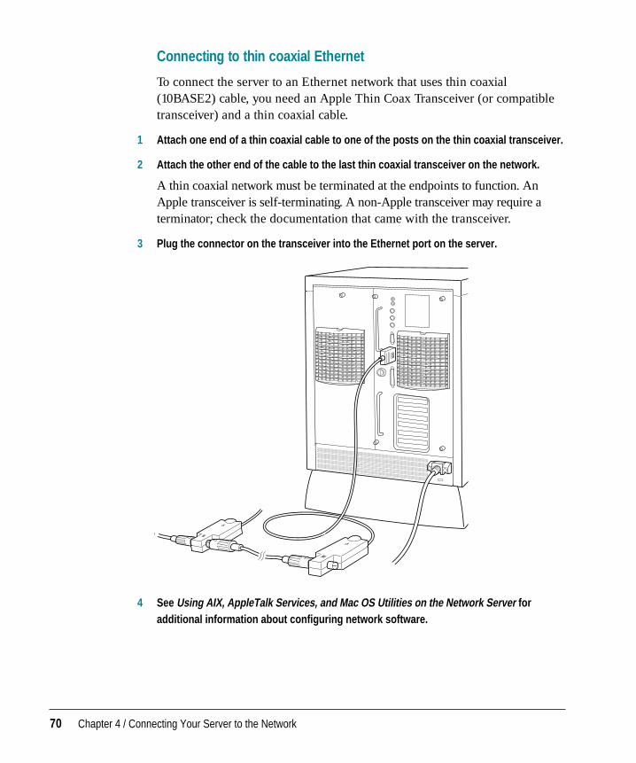
Connecting to thin coaxial Ethernet
To connect the server to an Ethernet network that uses thin coaxial(10BASE2) cable, you need an Apple Thin Coax Transceiver (or compatibletransceiver) and a thin coaxial cable.
1 Attach one end of a thin coaxial cable to one of the posts on the thin coaxial transceiver.
2 Attach the other end of the cable to the last thin coaxial transceiver on the network.
A thin coaxial network must be terminated at the endpoints to function. AnApple transceiver is self-terminating. A non-Apple transceiver may require aterminator; check the documentation that came with the transceiver.
3 Plug the connector on the transceiver into the Ethernet port on the server.
4 See Using AIX, AppleTalk Services, and Mac OS Utilities on the Network Server foradditional information about configuring network software.
70 Chapter 4 / Connecting Your Server to the Network
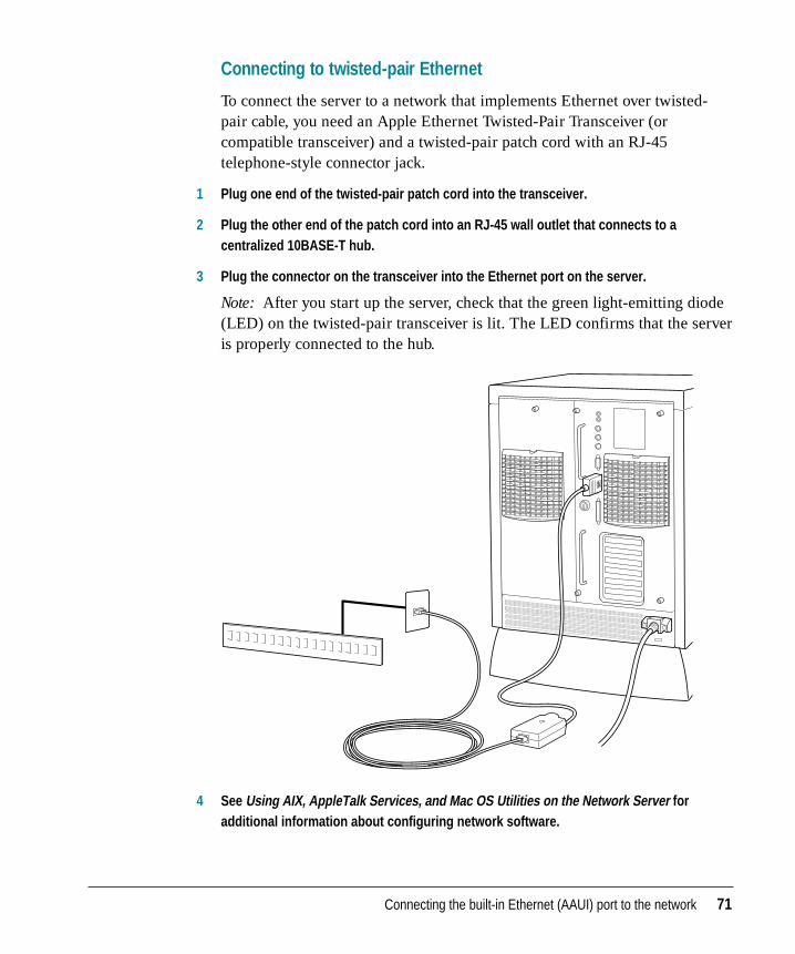
Connecting to twisted-pair Ethernet
To connect the server to a network that implements Ethernet over twisted-pair cable, you need an Apple Ethernet Twisted-Pair Transceiver (orcompatible transceiver) and a twisted-pair patch cord with an RJ-45telephone-style connector jack.
1 Plug one end of the twisted-pair patch cord into the transceiver.
2 Plug the other end of the patch cord into an RJ-45 wall outlet that connects to acentralized 10BASE-T hub.
3 Plug the connector on the transceiver into the Ethernet port on the server.
Note: After you start up the server, check that the green light-emitting diode(LED) on the twisted-pair transceiver is lit. The LED confirms that the serveris properly connected to the hub.
4 See Using AIX, AppleTalk Services, and Mac OS Utilities on the Network Server foradditional information about configuring network software.
Connecting the built-in Ethernet (AAUI) port to the network 71
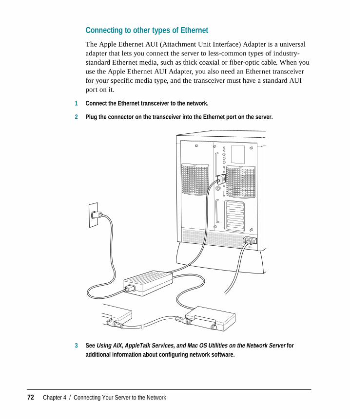
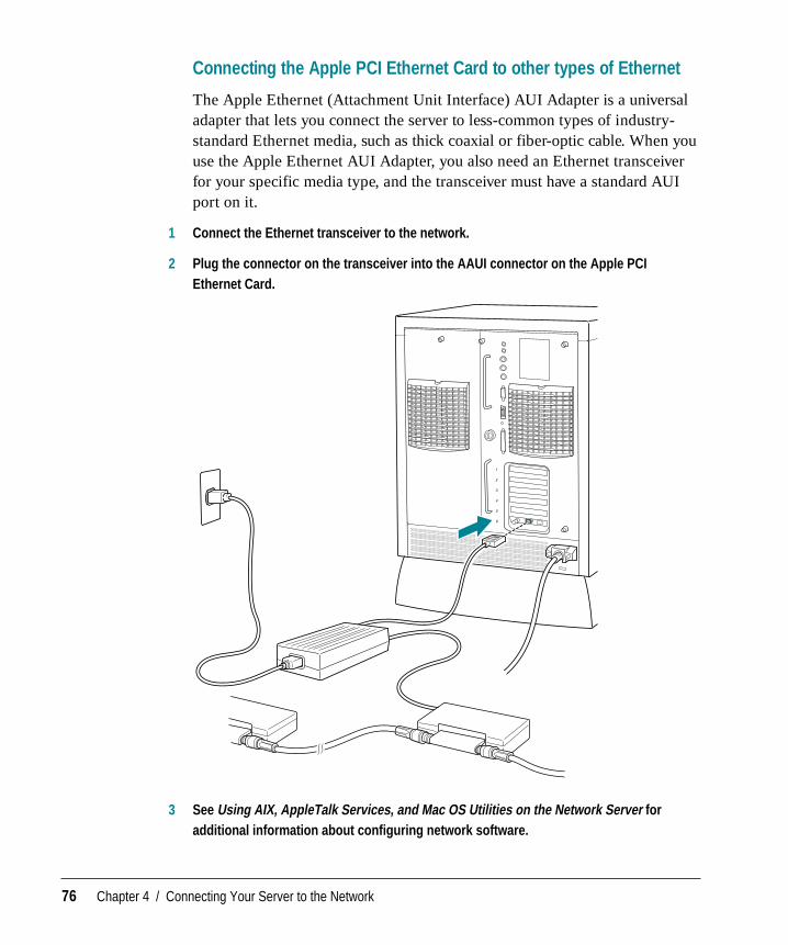
Connecting to other types of Ethernet
The Apple Ethernet AUI (Attachment Unit Interface) Adapter is a universaladapter that lets you connect the server to less-common types of industry-standard Ethernet media, such as thick coaxial or fiber-optic cable. When youuse the Apple Ethernet AUI Adapter, you also need an Ethernet transceiverfor your specific media type, and the transceiver must have a standard AUIport on it.
1 Connect the Ethernet transceiver to the network.
2 Plug the connector on the transceiver into the Ethernet port on the server.
3 See Using AIX, AppleTalk Services, and Mac OS Utilities on the Network Server foradditional information about configuring network software.
72 Chapter 4 / Connecting Your Server to the Network
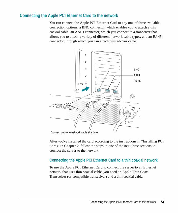
Connecting the Apple PCI Ethernet Card to the network
You can connect the Apple PCI Ethernet Card to any one of three availableconnection options: a BNC connector, which enables you to attach a thincoaxial cable; an AAUI connector, which you connect to a tranceiver thatallows you to attach a variety of different network cable types; and an RJ-45connector, through which you can attach twisted-pair cable.
After you’ve installed the card according to the instructions in “Installing PCICards” in Chapter 2, follow the steps in one of the next three sections toconnect the server to the network.
Connecting the Apple PCI Ethernet Card to a thin coaxial network
To use the Apple PCI Ethernet Card to connect the server to an Ethernetnetwork that uses thin coaxial cable, you need an Apple Thin CoaxTransceiver (or compatible transceiver) and a thin coaxial cable.
BNC
AAUI
RJ-45
Connect only one network cable at a time.
Connecting the Apple PCI Ethernet Card to the network 73
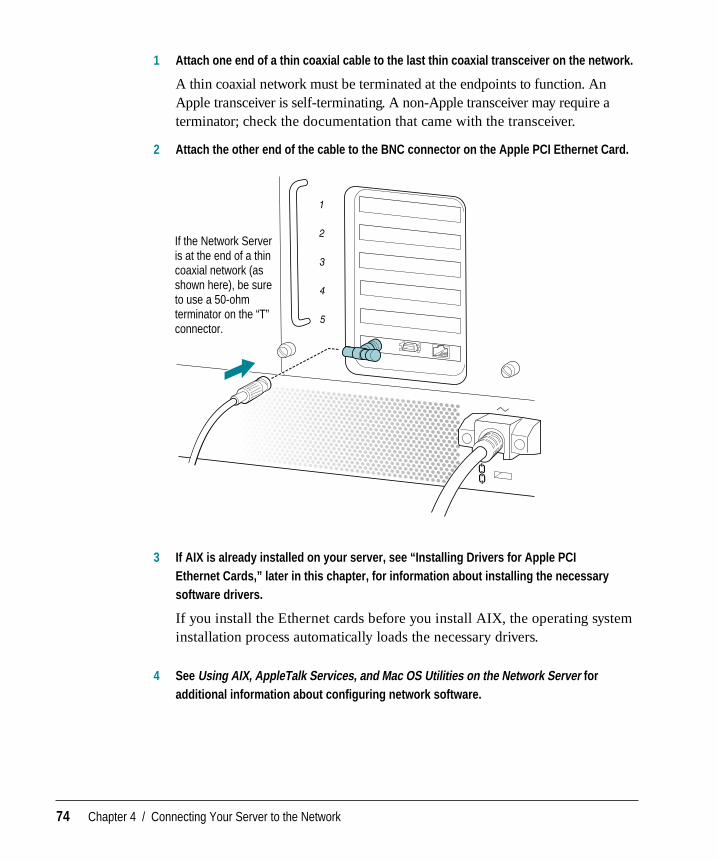
1 Attach one end of a thin coaxial cable to the last thin coaxial transceiver on the network.
A thin coaxial network must be terminated at the endpoints to function. AnApple transceiver is self-terminating. A non-Apple transceiver may require aterminator; check the documentation that came with the transceiver.
2 Attach the other end of the cable to the BNC connector on the Apple PCI Ethernet Card.
3 If AIX is already installed on your server, see “Installing Drivers for Apple PCI Ethernet Cards,” later in this chapter, for information about installing the necessarysoftware drivers.
If you install the Ethernet cards before you install AIX, the operating systeminstallation process automatically loads the necessary drivers.
4 See Using AIX, AppleTalk Services, and Mac OS Utilities on the Network Server foradditional information about configuring network software.
If the Network Server is at the end of a thin coaxial network (as shown here), be sure to use a 50-ohm terminator on the “T” connector.
74 Chapter 4 / Connecting Your Server to the Network
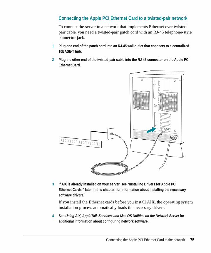
Connecting the Apple PCI Ethernet Card to a twisted-pair network
To connect the server to a network that implements Ethernet over twisted-pair cable, you need a twisted-pair patch cord with an RJ-45 telephone-styleconnector jack.
1 Plug one end of the patch cord into an RJ-45 wall outlet that connects to a centralized10BASE-T hub.
2 Plug the other end of the twisted-pair cable into the RJ-45 connector on the Apple PCIEthernet Card.
3 If AIX is already installed on your server, see “Installing Drivers for Apple PCI Ethernet Cards,” later in this chapter, for information about installing the necessarysoftware drivers.
If you install the Ethernet cards before you install AIX, the operating systeminstallation process automatically loads the necessary drivers.
4 See Using AIX, AppleTalk Services, and Mac OS Utilities on the Network Server foradditional information about configuring network software.
Connecting the Apple PCI Ethernet Card to the network 75
Connecting the Apple PCI Ethernet Card to other types of Ethernet
The Apple Ethernet (Attachment Unit Interface) AUI Adapter is a universaladapter that lets you connect the server to less-common types of industry-standard Ethernet media, such as thick coaxial or fiber-optic cable. When youuse the Apple Ethernet AUI Adapter, you also need an Ethernet transceiverfor your specific media type, and the transceiver must have a standard AUIport on it.
1 Connect the Ethernet transceiver to the network.
2 Plug the connector on the transceiver into the AAUI connector on the Apple PCIEthernet Card.
3 See Using AIX, AppleTalk Services, and Mac OS Utilities on the Network Server foradditional information about configuring network software.
76 Chapter 4 / Connecting Your Server to the Network
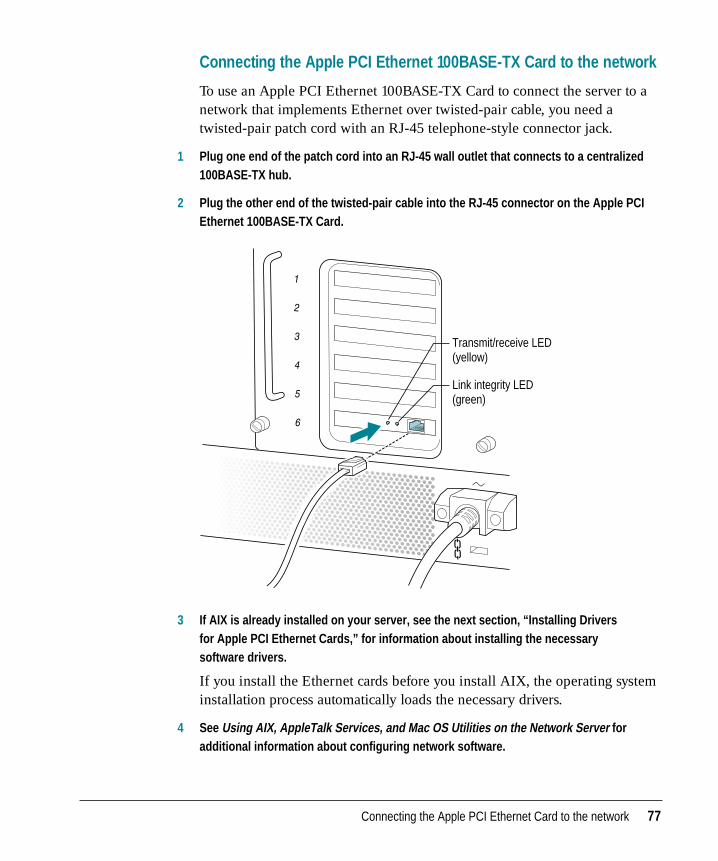
Connecting the Apple PCI Ethernet 100BASE-TX Card to the network
To use an Apple PCI Ethernet 100BASE-TX Card to connect the server to anetwork that implements Ethernet over twisted-pair cable, you need atwisted-pair patch cord with an RJ-45 telephone-style connector jack.
1 Plug one end of the patch cord into an RJ-45 wall outlet that connects to a centralized100BASE-TX hub.
2 Plug the other end of the twisted-pair cable into the RJ-45 connector on the Apple PCIEthernet 100BASE-TX Card.
3 If AIX is already installed on your server, see the next section, “Installing Drivers for Apple PCI Ethernet Cards,” for information about installing the necessary software drivers.
If you install the Ethernet cards before you install AIX, the operating systeminstallation process automatically loads the necessary drivers.
4 See Using AIX, AppleTalk Services, and Mac OS Utilities on the Network Server foradditional information about configuring network software.
Transmit/receive LED (yellow)
Link integrity LED (green)
Connecting the Apple PCI Ethernet Card to the network 77
Installing drivers for Apple PCI Ethernet Cards
After you install the Apple PCI Ethernet Card or the Apple PCI Ethernet100BASE-TX Card, you need to install software drivers in order for the cardsto work with AIX. These drivers automatically load during the AIXinstallation process, so if you install AIX after installing the cards, you don’tneed to go through any special steps to load the necessary drivers.
If you install one of the Apple PCI Ethernet Cards after AIX is alreadyinstalled on the server, follow these steps to install the appropriate drivers.
1 Log in as root.
2 Insert the Installation CD.
3 Start SMIT.
Enter this on the command line:
smit devinst
Or, go directly to the Install Additional Software menu, or use the SMIT pathDevices/Install Additional Device Software.
A dialog box appears prompting you to specify your input device.
4 Select CD-ROM as your input device and click OK.
To display the available input devices, use the List button.
78 Chapter 4 / Connecting Your Server to the Network
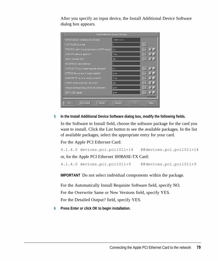
After you specify an input device, the Install Additional Device Softwaredialog box appears.
5 In the Install Additional Device Software dialog box, modify the following fields.
In the Software to Install field, choose the software package for the card youwant to install. Click the List button to see the available packages. In the listof available packages, select the appropriate entry for your card.
For the Apple PCI Ethernet Card:
4.1.4.0 devices.pci.pci1011+14 @@devices.pci.pci1011+14
or, for the Apple PCI Ethernet 100BASE-TX Card:
4.1.4.0 devices.pci.pci1011+9 @@devices.pci.pci1011+9
IMPORTANT Do not select individual components within the package.
For the Automatically Install Requisite Software field, specify NO.
For the Overwrite Same or New Versions field, specify YES.
For the Detailed Output? field, specify YES.
6 Press Enter or click OK to begin installation.
Connecting the Apple PCI Ethernet Card to the network 79
7 Restart your system.
Your driver is now installed. The next time you log in to AIX, enter thiscommand to ensure that the driver is installed and the card is recognized:
lsdev -C | grep -i ether
This command lists the known Ethernet devices and displays their status, asin this example:
ent0 Available 00-00-0E Apple on-board Ethernet
ent1 Available 00-14 Apple 10Mbit PCI Ethernet
8 See Using AIX, AppleTalk Services, and Mac OS Utilities on the Network Server foradditional information about configuring network software.
80 Chapter 4 / Connecting Your Server to the Network
This chapter describes how to start up your server and covers the normalstartup process, as well as how to solve problems that you might encounterduring the startup process.
5 Starting Up Your Server
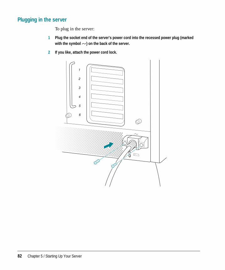
Plugging in the server
To plug in the server:
1 Plug the socket end of the server’s power cord into the recessed power plug (markedwith the symbol ≤) on the back of the server.
2 If you like, attach the power cord lock.
82 Chapter 5 / Starting Up Your Server
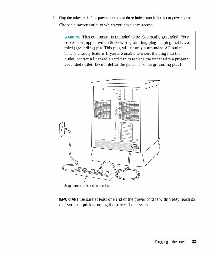
3 Plug the other end of the power cord into a three-hole grounded outlet or power strip.
Choose a power outlet to which you have easy access.
IMPORTANT Be sure at least one end of the power cord is within easy reach sothat you can quickly unplug the server if necessary.
Surge protector is recommended.
WARNING This equipment is intended to be electrically grounded. Yourserver is equipped with a three-wire grounding plug—a plug that has athird (grounding) pin. This plug will fit only a grounded AC outlet.This is a safety feature. If you are unable to insert the plug into theoutlet, contact a licensed electrician to replace the outlet with a properlygrounded outlet. Do not defeat the purpose of the grounding plug!
Plugging in the server 83
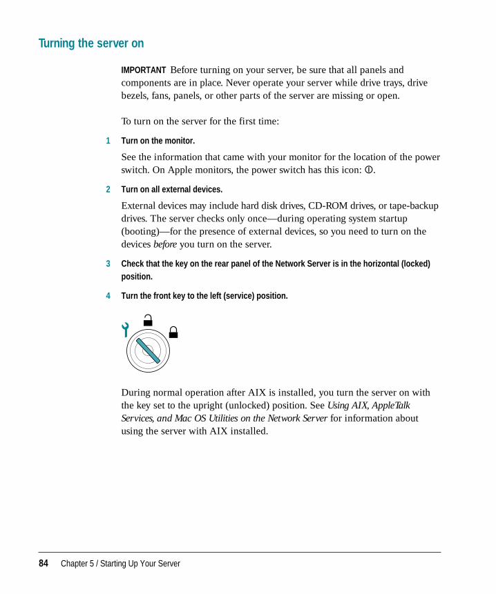
Turning the server on
IMPORTANT Before turning on your server, be sure that all panels andcomponents are in place. Never operate your server while drive trays, drivebezels, fans, panels, or other parts of the server are missing or open.
To turn on the server for the first time:
1 Turn on the monitor.
See the information that came with your monitor for the location of the powerswitch. On Apple monitors, the power switch has this icon: I.
2 Turn on all external devices.
External devices may include hard disk drives, CD-ROM drives, or tape-backupdrives. The server checks only once—during operating system startup(booting)—for the presence of external devices, so you need to turn on thedevices before you turn on the server.
3 Check that the key on the rear panel of the Network Server is in the horizontal (locked)position.
4 Turn the front key to the left (service) position.
During normal operation after AIX is installed, you turn the server on withthe key set to the upright (unlocked) position. See Using AIX, AppleTalkServices, and Mac OS Utilities on the Network Server for information aboutusing the server with AIX installed.
84 Chapter 5 / Starting Up Your Server
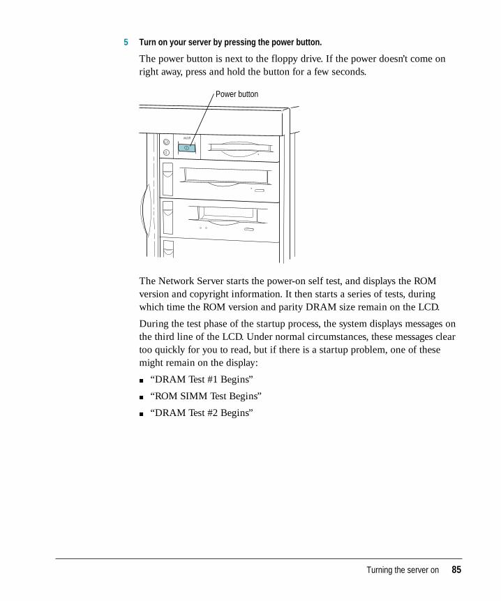
5 Turn on your server by pressing the power button.
The power button is next to the floppy drive. If the power doesn’t come onright away, press and hold the button for a few seconds.
The Network Server starts the power-on self test, and displays the ROMversion and copyright information. It then starts a series of tests, duringwhich time the ROM version and parity DRAM size remain on the LCD.
During the test phase of the startup process, the system displays messages onthe third line of the LCD. Under normal circumstances, these messages cleartoo quickly for you to read, but if there is a startup problem, one of thesemight remain on the display:
m “DRAM Test #1 Begins”
m “ROM SIMM Test Begins”
m “DRAM Test #2 Begins”
Power button
Turning the server on 85
The next test takes some time to complete, depending on the amount ofmemory in the server. This message appears at the beginning of the test:
m “LONG DRAM Test Begins”
Dashes appear to indicate the progress of DRAM testing. Depending onmemory size, there may be as much as 60 seconds between dashes. If theserver stops (“freezes” or “hangs”) with dashes displayed on the LCD, seethe next section for information about which memory component wasbeing tested at the time.
If the server stops (“freezes” or “hangs”) with one of the followingmessages displayed, that information may indicate a problem with thecomponent identified in the message. The component may have failed, orbe incorrectly installed, or be incompatible.
m “Turning on Caches”
m “Testing Parity DIMMs”
Check to see if parity DIMMs are installed. If any DIMM does not supportparity, the server treats all memory as nonparity.
m “MainLBU Enet Setup”
m “Sounding Boot Beep”
m “Sizing RAM DIMMs”
m “ROM SIMM Data Access”
m “Allocating RAM DIMMs”
m “MainLBU NVRAM Setup”
m “CPU Card Info Setup”
m “L2 Cache SIMM Setup”
m “Testing L2Cache SIMM”
m “RAM/ROM/NVRAM:PASSED”
For information about problem messages that may appear, see the nextsection.
After all the tests are complete, the LCD displays something similar to this:
ROM ver.1.1.22
0048 MB Parity DRAM
150 MHz 604, 50 MHz Bus
1024 KB Level 2 Cache
86 Chapter 5 / Starting Up Your Server
m See Using AIX, AppleTalk Services, and Mac OS Utilities on the Network Server forinformation about installing and using the operating system.
IMPORTANT If you need to turn off your server at any point, see “Turning theServer Off” later in this chapter. It is very important to use the correctprocedure for shutting down your server before turning it off.
Problems turning on your server?
If you don’t see anything on the screen, check these items to see if you canidentify the problem:
m Is the key on the rear panel in the horizontal (locked) position, and are theback panel thumbscrews fully tightened?
m Is the server turned on? The green power indicator should be lighted. Ifpower doesn’t come on immediately after you press the power button, pressand hold the button for a few seconds.
m Is the server plugged into a power source? If it is plugged into a powerstrip, is the power strip turned on?
m Has output been redirected to a serial port?
m Is the monitor turned on? (If the monitor has a power-on light on the front,check that it’s on.) Try turning the monitor off and then on again.
m Is the monitor power cord plugged in?
m Is the monitor’s cable attached firmly to both the monitor and server?
m Are the brightness and contrast controls on the monitor adjusted correctly?(On Apple monitors, the brightness control is marked with the symbol ¤,and the contrast control is marked with the symbol O.)
m Is the processor card firmly seated? See Chapter 2 for information on howto open the rear drawer that contains the processor card, and check that theprocessor card is securely placed in its socket.
m Does the long DRAM test never complete? Check to make sure eachDRAM DIMM is properly seated.
m Does the system fail to boot and is a memory failure indicated at addressECCBEBAD? Check your DRAM DIMM specifications. ECC memoryDIMMs with non-quad CAS logic are not supported.
Turning the server on 87
If there is a problem message displayed on the LCD on the front of the server, the component identified in the message may have failed, or beincorrectly installed, or be incompatible. These are among the possibleproblem messages:
m “L2 Cache SIMM Failed”Contact your service provider for replacement. The server can operate withthe L2 Cache SIMM removed.
m “ROM SIMM Failed”
m “MainLBU NVRAM Failed”The ROM, which is located on the main logic board unit, has failed.Contact your service provider for replacement. The server cannot operate with the ROM SIMM removed.
m “RAM DIMM 1A Failed at Address xxxxxxxx”RAM DIMMs are identified as 1A through 4A, and 1B through 4B.Addresses are in hexadecimal. Remove the failed DRAM DIMM and restart.
m “MainLBU Video ID Bad”The video subsystem is located on main logic board unit.
m “MainLBU 825#x Failed”The number indicates either SCSI controller 1 or 2, which are located onthe main logic board unit.
m “Drive Fan Failed!”This fan is located on the left side of the server rear panel, behind the drives.
m “Processor Fan Failed”This fan is on the right side of the server’s rear panel, on the rear drawer.
m “Temperature Too Hot!'”The internal cabinet temperature is unsafe. Turn off the serverimmediately.
m “Temperature Warning!”The internal cabinet temperature is becoming unsafe. Check that both fansare operating and that server air vents are clear.
88 Chapter 5 / Starting Up Your Server
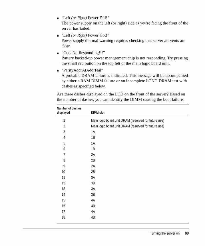
m “Left (or Right) Power Fail!”The power supply on the left (or right) side as you’re facing the front of theserver has failed.
m “Left (or Right) Power Hot!”Power supply thermal warning requires checking that server air vents areclear.
m “CudaNotResponding!!!”Battery backed-up power management chip is not responding. Try pressingthe small red button on the top left of the main logic board unit.
m “ParityAddrAtAddrFail”A probable DRAM failure is indicated. This message will be accompaniedby either a RAM DIMM failure or an incomplete LONG DRAM test withdashes as specified below.
Are there dashes displayed on the LCD on the front of the server? Based onthe number of dashes, you can identify the DIMM causing the boot failure.
Number of dashesdisplayed DIMM slot
1 Main logic board unit DRAM (reserved for future use)
2 Main logic board unit DRAM (reserved for future use)
3 1A
4 1B
5 1A
6 1B
7 2A
8 2B
9 2A
10 2B
11 3A
12 3B
13 3A
14 3B
15 4A
16 4B
17 4A
18 4B
Turning the server on 89
Turning the server off under normal circumstances
To turn the server off:
m If AIX is running, enter the command
shutdown -h
m If the Open Firmware prompt is displayed, enter the command
shut-down
Note that you need to include the hyphen in the shut-down command. Toturn on the server again, just press the power button on the front of the server.
IMPORTANT Be sure to shut down the server if you need to
m move the server
m connect other equipment to the server
m unplug the server
Restarting the server following a power interruption
The Network Server’s power control circuits operate in “file server mode.”This means that the server automatically powers up and restarts the operatingsystem (“boots”) if power is interrupted and then restored. For example, if apower outage occurs while the server is running, the server will automaticallyreboot itself when power is restored.
If you don’t want the Network Server to restart after a power interruption,disconnect the power cord or turn the key on the rear panel to the upright(unlocked) position before power is restored.
90 Chapter 5 / Starting Up Your Server
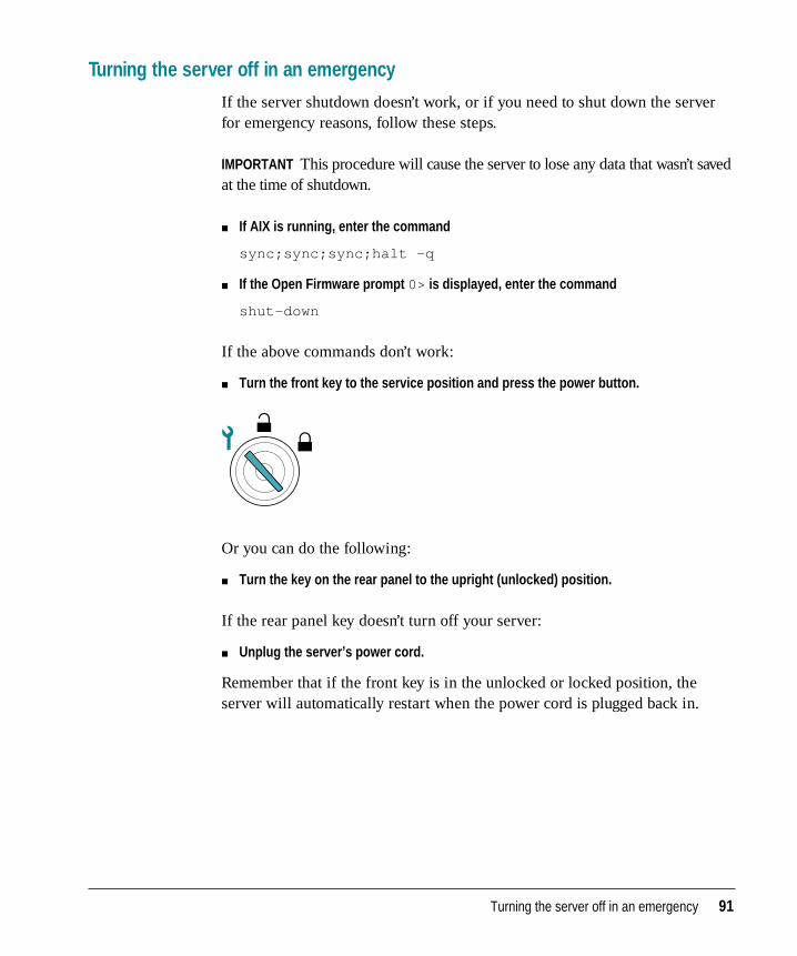
Turning the server off in an emergency
If the server shutdown doesn’t work, or if you need to shut down the serverfor emergency reasons, follow these steps.
IMPORTANT This procedure will cause the server to lose any data that wasn’t savedat the time of shutdown.
m If AIX is running, enter the command
sync;sync;sync;halt -q
m If the Open Firmware prompt 0> is displayed, enter the command
shut-down
If the above commands don’t work:
m Turn the front key to the service position and press the power button.
Or you can do the following:
m Turn the key on the rear panel to the upright (unlocked) position.
If the rear panel key doesn’t turn off your server:
m Unplug the server’s power cord.
Remember that if the front key is in the unlocked or locked position, theserver will automatically restart when the power cord is plugged back in.
Turning the server off in an emergency 91

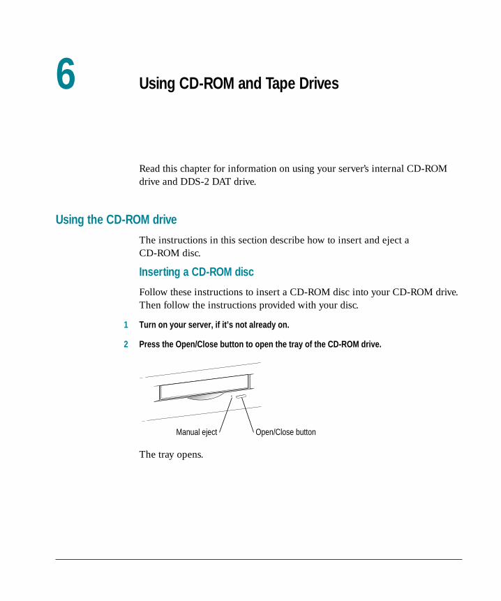
Read this chapter for information on using your server’s internal CD-ROMdrive and DDS-2 DAT drive.
Using the CD-ROM drive
The instructions in this section describe how to insert and eject a CD-ROM disc.
Inserting a CD-ROM disc
Follow these instructions to insert a CD-ROM disc into your CD-ROM drive.Then follow the instructions provided with your disc.
1 Turn on your server, if it’s not already on.
2 Press the Open/Close button to open the tray of the CD-ROM drive.
The tray opens.
Open/Close buttonManual eject
6 Using CD-ROM and Tape Drives

3 Place a CD-ROM disc in the tray, with the disc label facing up.
Make sure the disc is lying flat and centered in the tray.
4 Push the tray in, or press the Open/Close button, to close the tray.
The CD-ROM disc is ready to use.
Ejecting a CD-ROM disc
Follow these instructions to open the tray and eject a CD-ROM disc fromyour computer. If these instructions don’t work, insert a straightened paperclip into the manual eject hole. The manual eject works regardless of whetherthe server is turned on or turned off.
IMPORTANT You may not be able to eject a disc if it is being used. Quit anyapplications that are using the CD and unmount any file systems from it.
94 Chapter 6 / Using CD-ROM and Tape Drives
1 Open the tray.
Press the Open/Close button for your CD-ROM drive.
2 Take the CD-ROM disc out of the tray.
Store your disc in a safe place, away from heat, dust, and moisture.
3 Push the tray in, or press the Open/Close button to close the tray.
To avoid possible damage to the tray or the CD-ROM drive, keep the trayclosed when you are not using it.
Using the tape drive
The internal DDS-2 DAT drive and accompanying software can perform full orpartial backup and restore procedures for all of the data on your hard disks. Inaddition, the drive automatically performs error correction and datacompression of the files that you back up and restore. The error-correctionfeature helps ensure a high level of data integrity. The data-compressionfeature allows more data to fit on a cassette than do conventional backupmechanisms.
You can use AIX or software products from other companies to back up andrestore data. For information, see Using AIX, AppleTalk Services, and Mac OSUtilities on the Network Server or the backup utility’s documentation.
Compatible tapes
Your internal DAT drive is compatible with MRS-quality DDS (digital datastorage) tape cassettes. MRS (Media Recognition System) cassettes are thehighest-quality digital data tape available. Your internal tape drive requiresthis level of quality to perform backup operations successfully. See yourApple-authorized service provider for more MRS-quality DDS tape cassettesor their compatible substitutes. When selecting media, be sure the cassettes arestamped with these logos:
Media Recognition System
Digital Data Storage
Using the tape drive 95
If you use cassettes not approved by your Apple-authorized service provider,you void the warranty on your tape drive.
Note: Some vendors of computer products may refer to DDS cassettes asdigital audio tape (DAT) cassettes. However, DAT cassettes have a differentmechanical specification from DDS cassettes. Certain DAT cassettes may workwith your tape drive; your Apple-authorized service provider can tell youwhich ones will work.
Starting up the tape drive
The tape drive receives power and performs a self-test when you start upyour server. During the test, both status lights next to the tape drive openingare solid green, then the light on the left flashes green and the light on theright turns off. If no tape is loaded in the tape drive, both status lights turnoff. If a tape is loaded in the tape drive, the light on the left becomes solid green.
There are two conditions that indicate the self-test has failed. If the light onthe right flashes amber, you may need to clean the tape-drive head asdescribed in the section “Cleaning the Tape-Drive Heads” later in this chapter.Or if a tape is loaded in the tape drive, a flashing amber light may indicatethat the tape is worn and needs to be replaced. If the light on the rightbecomes solid amber, the tape drive did not successfully complete its self-testand should not be used; consult an Apple-authorized service provider.
The status lights are discussed in greater detail later in this chapter.
96 Chapter 6 / Using CD-ROM and Tape Drives
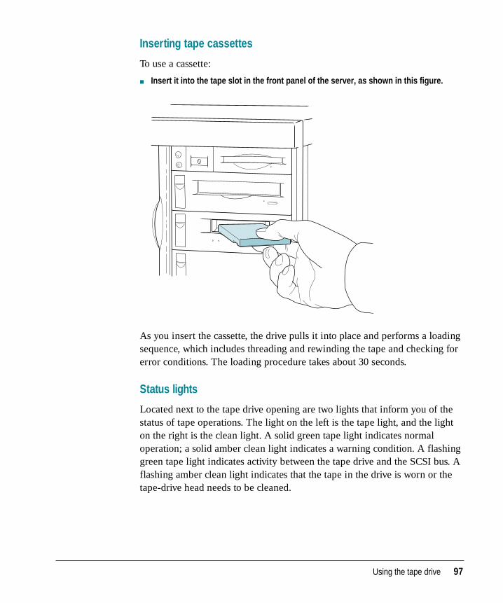
Inserting tape cassettes
To use a cassette:
m Insert it into the tape slot in the front panel of the server, as shown in this figure.
As you insert the cassette, the drive pulls it into place and performs a loadingsequence, which includes threading and rewinding the tape and checking forerror conditions. The loading procedure takes about 30 seconds.
Status lights
Located next to the tape drive opening are two lights that inform you of thestatus of tape operations. The light on the left is the tape light, and the lighton the right is the clean light. A solid green tape light indicates normaloperation; a solid amber clean light indicates a warning condition. A flashinggreen tape light indicates activity between the tape drive and the SCSI bus. Aflashing amber clean light indicates that the tape in the drive is worn or thetape-drive head needs to be cleaned.
Using the tape drive 97
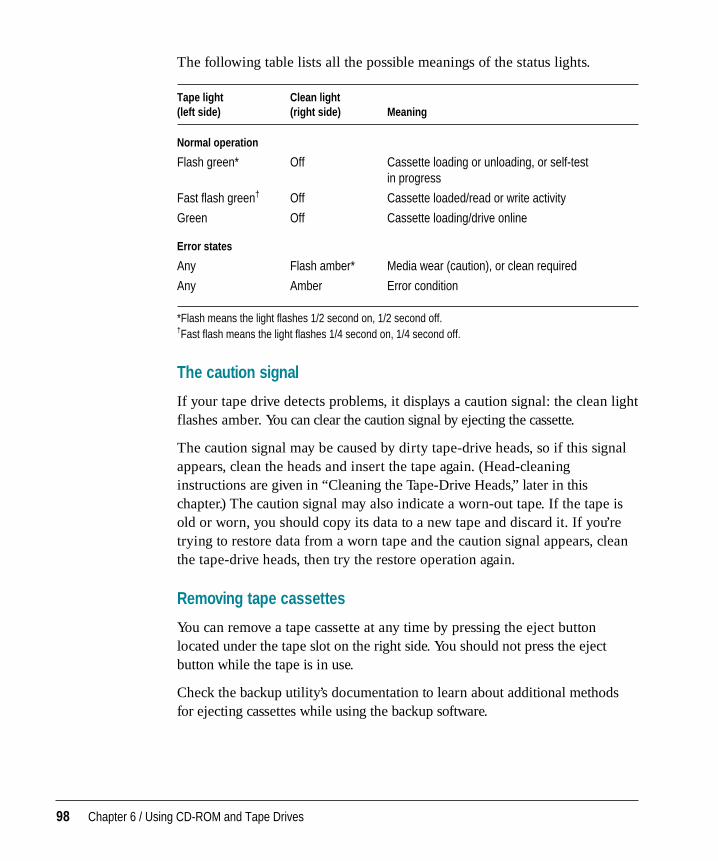
The following table lists all the possible meanings of the status lights.
Tape light Clean light(left side) (right side) Meaning
Normal operation
Flash green* Off Cassette loading or unloading, or self-testin progress
Fast flash green† Off Cassette loaded/read or write activity
Green Off Cassette loading/drive online
Error states
Any Flash amber* Media wear (caution), or clean required
Any Amber Error condition
*Flash means the light flashes 1/2 second on, 1/2 second off.†Fast flash means the light flashes 1/4 second on, 1/4 second off.
The caution signal
If your tape drive detects problems, it displays a caution signal: the clean lightflashes amber. You can clear the caution signal by ejecting the cassette.
The caution signal may be caused by dirty tape-drive heads, so if this signalappears, clean the heads and insert the tape again. (Head-cleaninginstructions are given in “Cleaning the Tape-Drive Heads,” later in thischapter.) The caution signal may also indicate a worn-out tape. If the tape isold or worn, you should copy its data to a new tape and discard it. If you’retrying to restore data from a worn tape and the caution signal appears, cleanthe tape-drive heads, then try the restore operation again.
Removing tape cassettes
You can remove a tape cassette at any time by pressing the eject buttonlocated under the tape slot on the right side. You should not press the ejectbutton while the tape is in use.
Check the backup utility’s documentation to learn about additional methodsfor ejecting cassettes while using the backup software.
98 Chapter 6 / Using CD-ROM and Tape Drives
Forcing the ejection of a tape cassette
If you need to force the ejection of a tape cassette:
m Hold the eject button down for at least 5 seconds (perform this step after the serverhas started up).
The drive waits 35 seconds for the normal eject procedure to occur, and if itdoes not occur, unthreads the tape and ejects the cartridge.
Locking a cassette
You can lock a DDS cassette by sliding the tab on the back of the cassette sothat the hole is visible. When a tape cassette is locked, data can be read fromthe cassette but not written to it.
Avoiding high humidity
Whenever your tape drive detects water condensation, both status lights glowsolid amber. This warning signal cancels any commands in progress.Furthermore, any commands that access the tape are rejected. The tape drivethen unthreads the tape to prevent tape and tape-head damage.
To minimize the chance of condensation, adhere to the environmentalrequirements described in Appendix B, and follow these general cassetteguidelines:
m Use tape cassettes at temperatures between 10˚ C (50˚ F) and 40˚ C (104˚ F).
m If you expose the tape cassettes to temperatures outside the operatinglimits, you can stabilize them by leaving them in the proper operatingtemperature for a minimum of two hours.
WARNING If you force an eject while the drive is busy, you may losedata or cause the tape to be invalidly formatted.
Using the tape drive 99
Follow these guidelines to avoid temperature problems:
m Avoid exposing cassettes to severe temperature conditions. For example,don’t store a cassette in a car in bright sunlight.
m Avoid transferring data to or from a tape cassette when the temperature ischanging by more than 10˚ F per hour (roughly 5˚ C per hour).
Cleaning the tape-drive heads
The most common reason for the display of a caution signal on the frontpanel is that the tape-drive heads are dirty. Although your tape drive has abuilt-in roller for cleaning the heads during normal operation, you still needto perform a separate cleaning step as part of preventive maintenance.
Your system comes with a cleaning cassette that you should use to clean thetape-drive heads after every 25 hours of running time.
Use only a DDS cleaning cassette. When you insert the cleaning cassette intothe drive, the drive automatically loads it and cleans the heads. When thecleaning process is completed, the drive automatically ejects the cassette.Keep a record of how many times you use the cleaning cassette. After 25 uses,replace it.
The interval at which you clean the tape drive depends on how often you useit. In general, if you back up daily, you should clean the drive weekly. If youback up weekly, you should clean the tape drive once a month.
For more information about using the cleaning cassette, refer to theinstructions that came with it. For additional cleaning cassettes, see yourApple-authorized service provider.
100 Chapter 6 / Using CD-ROM and Tape Drives
Important server safety instructions
For your own safety and that of your equipment, always take the following precautions.
Keep the front sliding door and rear drawer locked to prevent access byuntrained personnel. Access to the inside of the server should be limited tothose who are familiar with the hazards posed by the high energy levelswithin the server and who have the background and experience to safely workwith the components inside the system.
Turn off the server and disconnect the power plug (by pulling the plug, notthe cord) if any of the following conditions exists:
m The power cord or plug becomes frayed or otherwise damaged.
m You spill something into the case.
m Your server is exposed to rain or any other excess moisture.
m Your server has been dropped or the case has otherwise been damaged.
m You suspect that your server needs service or repair.
m You want to clean the case (use only the recommended proceduredescribed later in this section).
WARNING Electrical equipment may be hazardous if misused.Operation of this product, or similar products, must always besupervised by an adult. Do not allow children access to the interior ofany electrical product, and do not permit them to handle any cables.
Appendix A Safety, Maintenance, and Health Information
For additional safety:
m If you ever need to remove a side panel or front drive tray of your server,replace it before you use the server.
m Never turn on your server with any of the external enclosure, includingcabinet panels or drive trays, removed.
Be sure that you always do the following:
m Keep the server locked during normal operation, and if possible, keep theserver in a locked and unused room or closet with limited access.
m Keep your server away from sources of liquids, such as wash basins,bathtubs, shower stalls, and so on.
m Protect your server from dampness or wet weather, such as rain, snow, andso on.
m Read all the installation instructions carefully before you plug your serverinto a wall socket.
m Keep these instructions handy for reference by you and others.
m Follow all instructions and warnings dealing with your system.
Handling your computer equipment
Follow these guidelines for handling your server and its components:
m When setting up your server, place components on a sturdy, flat surface,and carefully follow all setup instructions.
m When connecting or disconnecting a cable, always hold the cable by itsconnector (the plug, not the cord).
WARNING If you have a problem with your server and nothing in themanuals that came with the server solves the problem, consult theservice and support information that came with your server forinformation on how to contact an Apple-authorized service provider orApple for assistance.
102 Appendix A / Safety, Maintenance, and Health Information
m Turn off your server and all its components before connecting ordisconnecting any cables to add or remove any component. Failure to do socould seriously damage your equipment.
m Never force a connector into a port. If the connector and port do not joinwith reasonable ease, they probably don’t match. Make sure that theconnector matches the port and that you have positioned the connectorcorrectly in relation to the port.
m Take care not to spill any food or liquid on the server, keyboard, mouse, orother components. If you do, turn your server off immediately and unplugit before cleaning up the spill. Depending on what you spilled and howmuch of it got into your equipment, you may have to bring your equipmentto an Apple-authorized service provider for repair.
m Protect the server and its components from direct sunlight and rain orother moisture.
m Keep all ventilation openings clear and unobstructed. Without proper aircirculation, components can overheat, causing damage or unreliable operation.
Handling the monitor
Follow these procedures for handling the monitor:
m Turn down the screen brightness control if you leave the server turned onfor extended periods. If the brightness is not turned down, the image on thescreen could “burn in” and damage the screen.
You can also use a “screen-saver” program, which dims or varies the imageon the screen when the server has been idle for a specified period of time.These programs are available from independent suppliers and user groups.
m Make sure that the ventilation openings on the server and the monitor areclear and unobstructed.
m If there is interference on the monitor’s screen or on a television or radionear your server, move the affected equipment farther away.
Handling your computer equipment 103
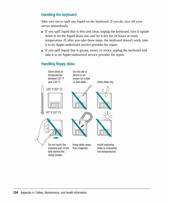
Handling the keyboard
Take care not to spill any liquid on the keyboard. If you do, turn off yourserver immediately.
m If you spill liquid that is thin and clear, unplug the keyboard, turn it upsidedown to let the liquid drain out, and let it dry for 24 hours at roomtemperature. If, after you take these steps, the keyboard doesn’t work, takeit to an Apple-authorized service provider for repair.
m If you spill liquid that is greasy, sweet, or sticky, unplug the keyboard andtake it to an Apple-authorized service provider for repair.
Handling floppy disks
125° F (52° C)
50° F (10° C)
Keep disks dry.
Do not use a pencil or an eraser on a disk or disk label.
Store disks at temperatures between 50° F and 125° F.
Do not touch the exposed part of the disk behind the metal shutter.
Keep disks away from magnets.
Avoid exposing disks to extremely hot temperatures.
104 Appendix A / Safety, Maintenance, and Health Information
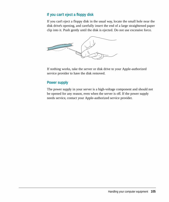
If you can’t eject a floppy disk
If you can’t eject a floppy disk in the usual way, locate the small hole near thedisk drive’s opening, and carefully insert the end of a large straightened paperclip into it. Push gently until the disk is ejected. Do not use excessive force.
If nothing works, take the server or disk drive to your Apple-authorizedservice provider to have the disk removed.
Power supply
The power supply in your server is a high-voltage component and should notbe opened for any reason, even when the server is off. If the power supplyneeds service, contact your Apple-authorized service provider.
Handling your computer equipment 105
Cleaning your equipment
Follow these general rules when cleaning the outside of your server and its components:
m Use a damp, soft, lint-free cloth to clean the server’s exterior. Avoid gettingmoisture in any openings.
m Don’t use aerosol sprays, solvents, or abrasives.
Cleaning the server case
To clean the server case:
1 Turn off the server and disconnect the power plug. (Pull the plug, not the cord.)
2 Wipe the surfaces lightly with a clean, soft cloth dampened with water.
Cleaning the monitor
To clean the screen, put household glass cleaner on a soft cloth and wipe thescreen. Don’t spray the cleaner directly on the screen because the liquid mightdrip into the monitor or server.
Cleaning the mouse
The mouse contains a small ball that must roll smoothly for the mouse towork properly. You can keep this ball free of dirt and grease by using themouse on a clean, lint-free surface and cleaning it occasionally.
You need a few cotton swabs and a clean, soft, lint-free cloth.
1 Turn off your server.
106 Appendix A / Safety, Maintenance, and Health Information
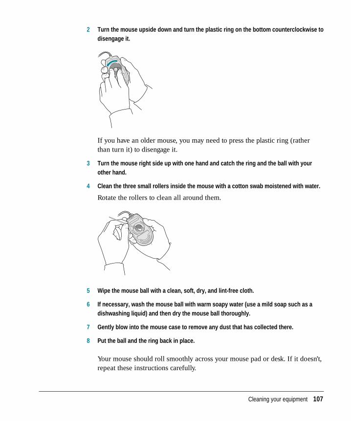
2 Turn the mouse upside down and turn the plastic ring on the bottom counterclockwise todisengage it.
If you have an older mouse, you may need to press the plastic ring (ratherthan turn it) to disengage it.
3 Turn the mouse right side up with one hand and catch the ring and the ball with yourother hand.
4 Clean the three small rollers inside the mouse with a cotton swab moistened with water.
Rotate the rollers to clean all around them.
5 Wipe the mouse ball with a clean, soft, dry, and lint-free cloth.
6 If necessary, wash the mouse ball with warm soapy water (use a mild soap such as adishwashing liquid) and then dry the mouse ball thoroughly.
7 Gently blow into the mouse case to remove any dust that has collected there.
8 Put the ball and the ring back in place.
Your mouse should roll smoothly across your mouse pad or desk. If it doesn’t,repeat these instructions carefully.
Cleaning your equipment 107
Health-related information about computer use
Muscle soreness, eye fatigue, and other discomforts and injuries sometimesassociated with using computers can occur from performing any number ofactivities. In fact, misuse of the same muscles during multiple activities cancreate a problem that might not otherwise exist. For example, if you engage innonwork activities that involve repetitive stress on the wrist—such asbicycling—and also use your computer keyboard improperly, you mayincrease your likelihood of developing wrist problems. Some individuals areat greater risk of developing these problems because of their health,physiology, lifestyle, and general exposure to stress. Work organization andconditions, such as workstation setup and lighting, also play a part in youroverall health and comfort. Preventing health problems is a multifaceted taskthat requires careful attention to the way you use your body every hour ofevery day.
The most common health effects associated with using a computer aremusculoskeletal discomfort and eye fatigue. We’ll discuss each area ofconcern below. For information about electric and magnetic emissions, lookin the reference material that came with your server.
Musculoskeletal discomfort
As with any activity that involves sitting for long periods of time, using acomputer can make your muscles sore and stiff. To minimize these effects, setup your work environment carefully, using the guidelines that follow, and takefrequent breaks to rest tired muscles. To make working with your computermore comfortable, allow enough space in your work area so that you canchange position frequently and maintain a relaxed posture.
Another type of musculoskeletal concern is repetitive stress injuries (RSIs),also known as cumulative trauma disorders (CTDs). These problems canoccur when a certain muscle or tendon is repeatedly overused and forced intoan unnatural position. The exact causes of RSIs are not totally understood, butin addition to awkward posture, such factors as the amount of repetition, theforce used in the activity, the individual’s physiology, workplace stress level,and lifestyle may affect the likelihood of experiencing an RSI.
108 Appendix A / Safety, Maintenance, and Health Information
RSIs did not suddenly arise when computers were invented; tennis elbow andwriter’s cramp, for example, are two RSIs that have been with us for a longtime. Although less common than other RSIs, one serious RSI discussed moreoften today is a wrist problem called carpal tunnel syndrome, which may beaggravated by improper use of computer keyboards. This nerve disorderresults from excessive pressure on the median nerve as it passes through thewrist to the hand.
This section offers advice on setting up your work area to enhance yourcomfort while you use your computer. Since the effects of repetitivemovements associated with using a computer can be compounded by those ofother work and leisure activities to produce or aggravate physical problems,proper use of your computer system must be considered as just one elementof a healthy lifestyle.
No one, of course, can guarantee that you won’t have problems even when youfollow the most expert advice on using computer equipment. You shouldalways check with a qualified health specialist if muscle, joint, or eyeproblems occur.
Eye fatigue
Eye fatigue can occur whenever the eyes are focused on a nearby object for along time. This problem occurs because the eye muscles must work harder toview an object that’s closer than about 20 feet (6 meters). Improper lightingcan hasten the development of eye fatigue. Although eye fatigue is annoying,there’s no evidence that it leads to permanent damage.
Whenever you’re engaged in an activity that involves close-up work—such asreading a magazine, doing craft work, or using a computer—be sure to havesufficient glare-free lighting and give your eyes frequent rest breaks bylooking up and focusing on distant objects. Remember to have your eyesexamined regularly.
To prevent discomfort and eye fatigue:
m Arrange your workspace so that the furniture is properly adjusted for youand doesn’t contribute to an awkward working posture.
m Take frequent short breaks to give your muscles and eyes a chance to rest.
Health-related information about computer use 109

Arranging your office
Here are some guidelines for adjusting the furniture in your office toaccommodate your physical size and shape.
m An adjustable chair that provides firm, comfortable support is best. Adjustthe height of the chair so that your thighs are horizontal and your feet flaton the floor.
The back of the chair should support your lower back (lumbar region).Follow the manufacturer’s instructions for adjusting the backrest to fit yourbody properly.
m When you use the computer keyboard, your shoulders should be relaxed.Your upper arm and forearm should form an approximate right angle, withyour wrist and hand in roughly a straight line.
You may have to raise your chair so that your forearms and hands are at theproper angle to the keyboard. If this makes it impossible to rest your feetflat on the floor, you can use a footrest with adjustable height and tilt tomake up for any gap between the floor and your feet. Or you may lowerthe desktop to eliminate the need for a footrest. Another option is to use adesk with a keyboard tray that’s lower than the regular work surface.
m Position the mouse at the same height as your keyboard. Allow adequatespace to use the mouse comfortably.
Thighs horizontal
Shoulders relaxed
Screen positioned to avoid reflected glare
Forearms and hands in a straight line
Forearms level or tilted up slightly
Lower back supported
Feet flat on the floor
Top of the screen at or slightly below eye level (You may need to adjust the height of your monitor by placing something under it or by raising your work surface.)
Clearance under work surface
45–70 cm (18–28 in.)
110 Appendix A / Safety, Maintenance, and Health Information
m Arrange the monitor so that the top of the screen is slightly below your eyelevel when you’re sitting at the keyboard. The best distance from your eyesto the screen is up to you, although most people seem to prefer 18 to 28inches (45 to 70 cm).
m Position the monitor to minimize glare and reflections on the screen fromoverhead lights and windows. You may want to use a tiltable monitorstand. The stand lets you set the monitor at the best angle for viewing,helping to reduce or eliminate glare from lighting sources you can’t move.
Avoiding fatiguem Change your seated position, stand up, or stretch whenever you start to feel
tired. Frequent short breaks are helpful in reducing fatigue.
m Use a light touch when typing or using a mouse and keep your hands andfingers relaxed.
m Some computer users may develop discomfort in their hands, wrists, or armsafter intensive work without breaks. If you begin to develop chronic pain ordiscomfort in your hands, wrists, or arms, consult a qualified health specialist.
m Allow adequate workspace so that you can use your keyboard and mousecomfortably. Place papers or other items so that you can view them easilywhile using your computer. A document stand may make reading papersmore comfortable.
m Eye muscles must work harder to focus on nearby objects. Occasionallyfocus your eyes on a distant object, and blink often while you work.
m Clean your screen regularly. Keeping the screen clean helps reduceunwanted reflections.
Health-related information about computer use 111

What about electromagnetic emissions?
There has been recent public discussion of the possible health effects ofprolonged exposure to extremely low frequency (ELF) and very lowfrequency (VLF) electromagnetic fields. Such fields are associated withelectromagnetic sources such as television sets, electrical wiring, and somehousehold appliances—as well as computer monitors.
Apple has reviewed scientific reports and sought the counsel of governmentregulatory agencies and respected health organizations. Based on theprevailing evidence and opinions, Apple believes that the electric andmagnetic fields produced by computer monitors do not pose a health risk.
In response to those customers who wish to reduce their exposure toelectromagnetic fields, Apple has lowered the emission levels of our products.We are also actively encouraging further scientific research so we cancontinue to promote the health and safety of our customers and employees.
112 Appendix A / Safety, Maintenance, and Health Information
The technical specifications in this chapter were accurate at the time ofprinting, but may have changed by the time your server shipped. See the file/usr/lpp/bos/README for the latest information.
Specifications
Processor
m PowerPC 604 at 132 megahertz (MHz) on the 500 model, 150 MHz on the700 model
m 32 kilobytes (KB) of on-chip cache
Memory
m A minimum of 32 megabytes (MB) of 60ns parity DRAM, expandable to amaximum of 512 MB through 8 DIMM sockets
m 4 MB read-only memory (ROM)
m 8 KB of nonvolatile parameter memory
m 512 KB of static RAM used as a Level 2 cache for the PowerPC processoron the 500 model; 1 MB on the 700 model
Disk drives
m Apple SuperDrive 1.4 MB high-density floppy disk drive
m Optional internal Apple SCSI-2 Fast and Wide hard disk drive
m Internal 5.25-inch quadruple-speed (600 kilobyte per second)CD-ROM player
Appendix B Technical Information
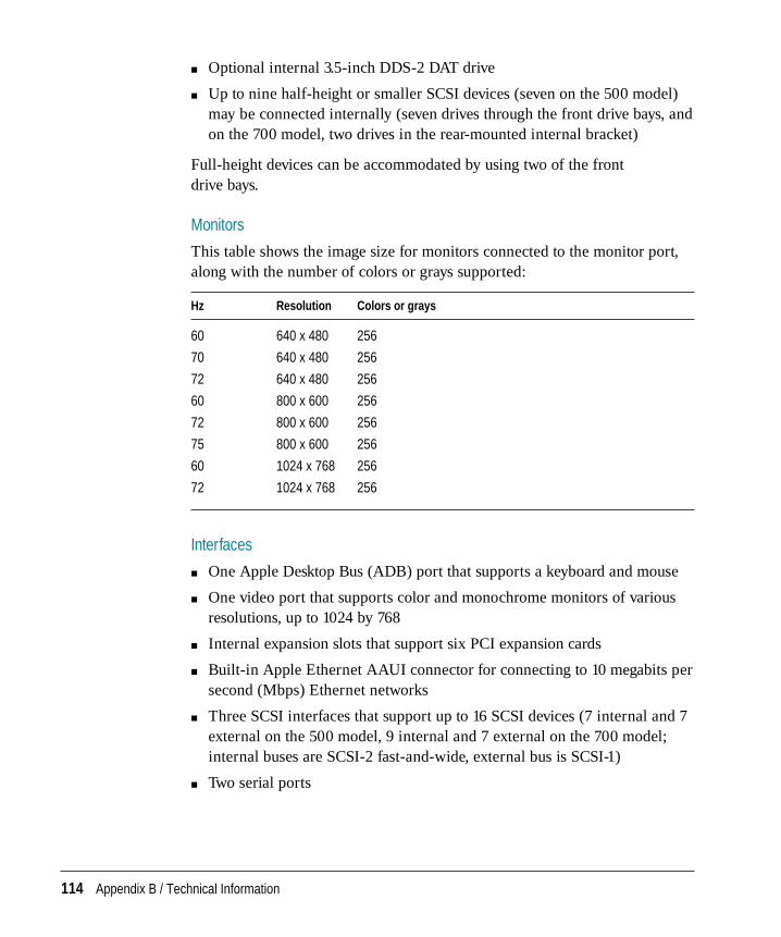
m Optional internal 3.5-inch DDS-2 DAT drive
m Up to nine half-height or smaller SCSI devices (seven on the 500 model)may be connected internally (seven drives through the front drive bays, andon the 700 model, two drives in the rear-mounted internal bracket)
Full-height devices can be accommodated by using two of the front drive bays.
Monitors
This table shows the image size for monitors connected to the monitor port,along with the number of colors or grays supported:
Hz Resolution Colors or grays
60 640 x 480 256
70 640 x 480 256
72 640 x 480 256
60 800 x 600 256
72 800 x 600 256
75 800 x 600 256
60 1024 x 768 256
72 1024 x 768 256
Interfaces
m One Apple Desktop Bus (ADB) port that supports a keyboard and mouse
m One video port that supports color and monochrome monitors of variousresolutions, up to 1024 by 768
m Internal expansion slots that support six PCI expansion cards
m Built-in Apple Ethernet AAUI connector for connecting to 10 megabits persecond (Mbps) Ethernet networks
m Three SCSI interfaces that support up to 16 SCSI devices (7 internal and 7external on the 500 model, 9 internal and 7 external on the 700 model;internal buses are SCSI-2 fast-and-wide, external bus is SCSI-1)
m Two serial ports
114 Appendix B / Technical Information
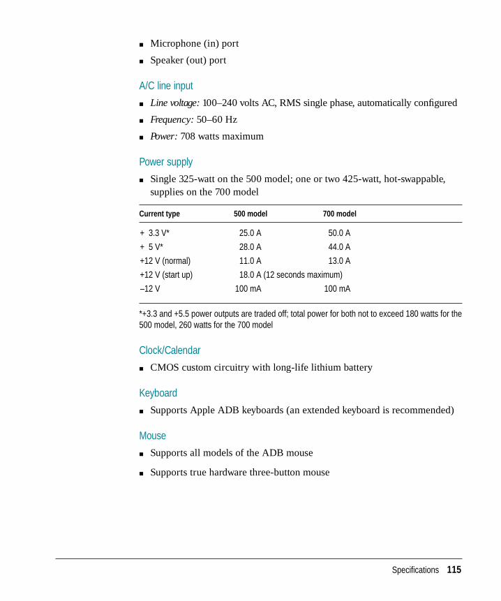
m Microphone (in) port
m Speaker (out) port
A/C line input
m Line voltage: 100–240 volts AC, RMS single phase, automatically configured
m Frequency: 50–60 Hz
m Power: 708 watts maximum
Power supply
m Single 325-watt on the 500 model; one or two 425-watt, hot-swappable,supplies on the 700 model
Current type 500 model 700 model
+ 3.3 V* 25.0 A 50.0 A
+ 5 V* 28.0 A 44.0 A
+12 V (normal) 11.0 A 13.0 A
+12 V (start up) 18.0 A (12 seconds maximum)
–12 V 100 mA 100 mA
*+3.3 and +5.5 power outputs are traded off; total power for both not to exceed 180 watts for the500 model, 260 watts for the 700 model
Clock/Calendar
m CMOS custom circuitry with long-life lithium battery
Keyboard
m Supports Apple ADB keyboards (an extended keyboard is recommended)
Mouse
m Supports all models of the ADB mouse
m Supports true hardware three-button mouse
Specifications 115
DRAM configurations
DRAM is provided in packages called Dual Inline Memory Modules, or DIMMs.
Your server can work with any of several DRAM configurations, depending onthe density of the DRAM chips that are mounted on the DIMMs. The 168-pinparity DIMMs used in the Network Server are available from Apple in sizes of8, 16, and 32 MB pairs, enabling you to increase Network Server memory by16, 32, and 64 MB, respectively. Your server can have a maximum of 512 MBof memory.
IMPORTANT The DIMMs should be 72-bit-wide 168-pin fast-paged mode, 60-nanosecond (ns) RAM access time or faster. DRAM must support byte writes.SIMMs and some DIMMs from older Macintosh computers will not work inthe Network Server. The parity DIMMS should be installed in matched pairs(for example, two 16 MB DIMMs, one in slot 1A, the other in slot 1B).Nonparity DRAM with 70-nanosecond DRAM access time or faster willwork; however, if there is any nonparity DRAM installed, all server paritychecking is disabled. Consult an Apple-authorized dealer or service providerfor information and upgrades.
Power requirements
Apple Desktop Busm Maximum power draw for all ADB devices: 500 milliampere (mA)
m Apple mouse draws up to 10 mA
m Keyboard draws 25–80 mA (varies with keyboard model used)
Note: It is recommended that you connect no more than three ADB devices tothe Network Server.
Expansion cards and devices
If you add a PCI expansion card, or an internal SCSI device to your server,make sure the component doesn’t exceed its maximum power allowance fromthe different voltage sources. Note that no single PCI card should exceed the25 watt limit of the PCI Revision 2.1 specification. Follow these guidelines.
116 Appendix B / Technical Information
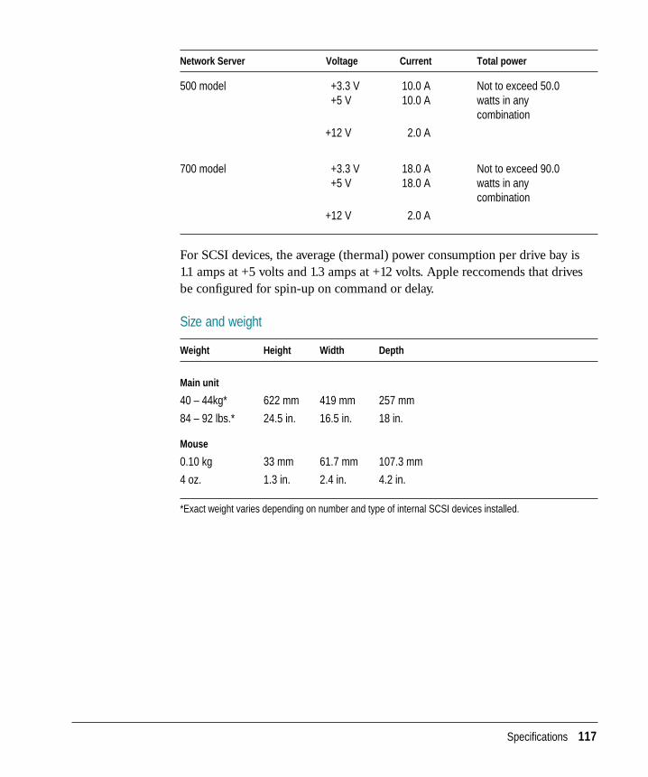
Network Server Voltage Current Total power
500 model +3.3 V 10.0 A Not to exceed 50.0 +5 V 10.0 A watts in any
combination
+12 V 2.0 A
700 model +3.3 V 18.0 A Not to exceed 90.0 +5 V 18.0 A watts in any
combination
+12 V 2.0 A
For SCSI devices, the average (thermal) power consumption per drive bay is 1.1 amps at +5 volts and 1.3 amps at +12 volts. Apple reccomends that drivesbe configured for spin-up on command or delay.
Size and weight
Weight Height Width Depth
Main unit
40 – 44kg* 622 mm 419 mm 257 mm
84 – 92 lbs.* 24.5 in. 16.5 in. 18 in.
Mouse
0.10 kg 33 mm 61.7 mm 107.3 mm
4 oz. 1.3 in. 2.4 in. 4.2 in.
*Exact weight varies depending on number and type of internal SCSI devices installed.
Specifications 117
Environment
Ambient operating temperature
m 10° C to 40° C (50° F to 104° F)
Storage temperature
m –40° C to 47° C (–40° F to 116.6° F)
Relative humidity
m With a DAT drive: 20% to 80% (noncondensing)
m Without a DAT drive: 5% to 95% (noncondensing)
Altitude
m 0 to 3048 m (0 to 10,000 ft.)
118 Appendix B / Technical Information
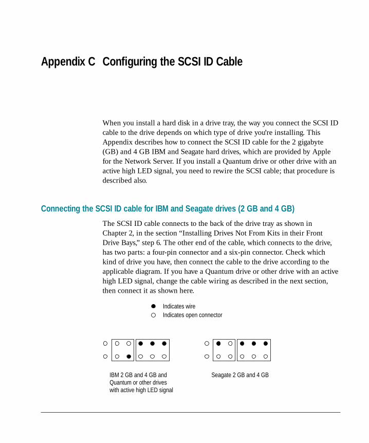
When you install a hard disk in a drive tray, the way you connect the SCSI IDcable to the drive depends on which type of drive you’re installing. ThisAppendix describes how to connect the SCSI ID cable for the 2 gigabyte(GB) and 4 GB IBM and Seagate hard drives, which are provided by Applefor the Network Server. If you install a Quantum drive or other drive with anactive high LED signal, you need to rewire the SCSI cable; that procedure isdescribed also.
Connecting the SCSI ID cable for IBM and Seagate drives (2 GB and 4 GB)
The SCSI ID cable connects to the back of the drive tray as shown in Chapter 2, in the section “Installing Drives Not From Kits in their FrontDrive Bays,” step 6. The other end of the cable, which connects to the drive,has two parts: a four-pin connector and a six-pin connector. Check whichkind of drive you have, then connect the cable to the drive according to theapplicable diagram. If you have a Quantum drive or other drive with an activehigh LED signal, change the cable wiring as described in the next section,then connect it as shown here.
IBM 2 GB and 4 GB and Quantum or other drives with active high LED signal
Indicates wireIndicates open connector
Seagate 2 GB and 4 GB
Appendix C Configuring the SCSI ID Cable
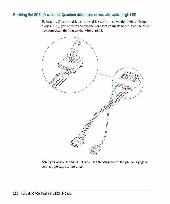
Rewiring the SCSI ID cable for Quantum drives and drives with active high LED
To install a Quantum drive or other drive with an active high light-emittingdiode (LED), you need to remove the wire that connects to pin 3 on the drivetray connector, then insert the wire at pin 1.
After you rewire the SCSI ID cable, see the diagram on the previous page toconnect the cable to the drive.
1 2 3 4 5 6
1 2 3 4 5 6
120 Appendix C / Configuring the SCSI ID Cable
10BASE-T hub, connecting RJ-45 wall outlet to71, 75
100BASE-TX hub, connecting RJ-45 wall outlet to 77
AAAUI connector port, for Apple PCI Ethernet Card
73, 76AAUI port 5, 68–69AC surge protectors, for powerline surges 46active high LED drives, rewiring the SCSI ID cable
for 120ADB (Apple Desktop Bus), power
requirements 116ADB (Apple Desktop Bus) port
icon for 66illustrated 4resetting input to 65technical specifications for 114
ADB-compatible extended keyboard. See alsokeyboards
connecting 65–66ADB icon, illustrated 66AIX operating system
Apple PCI Ethernet Cards drivers and 74emergency shut down 91further information about ixreplacing fans and 44using three-button mouse with 2version required for Network Server 5
altitudes, for operating Network Server 118antistatic mat 10, 12Apple Desktop Bus. See ADBApple Ethernet AAUI connector, technical
specifications for 114Apple Ethernet AUI Adapter 68, 72, 76Apple Ethernet Thin Coax Transceiver 68, 70,
71, 74Apple Ethernet Twisted-Pair Transceiver 68, 71Apple Multiple Scan 14 Display 61Apple Multiple Scan 15 Display 61Apple Multiple Scan 17 Display 61Apple Multiple Scan 20 Display 61Apple PCI Ethernet Cards
connecting to thin coaxial network 73–74connecting to twisted-pair network 75installing device drivers for 78–80100BASE-TX Card 77, 78–79power requirements for 116–117
Apple PCI Ethernet 100BASE-TX Cardconnecting to network 77installing device drivers for 78–80
AppleTalk protocol stack, required for NetworkServer 5
AUI media adapter 68AUI port 72, 76Automatically Install Requisite Software field
(Install Additional Device Software dialogbox) 79
Index
Bbacking up data, with DDS-2 DAT tape drives 95base cover, release buttons for 2baud rates
setenv command and 65for terminal emulation software 64
bezelsfor full-height disk drives 26replacing for CD-ROM drives 29
BNC connector port, attaching to Apple PCIEthernet Card 74
brightness controls, icon for 87bus assignments, for internal SCSI devices 23buses. See SCSI busesbus speeds, internal 22buttons
interrupt 2Open/Close 93power 2, 85, 87reset 2
Ccables 64
attaching for free-standing drives 29fiber optic 72impedance for SCSI 58LED 29locking 47–48monitor 62–63safety tips for connecting 103SCSI adapter 29, 39SCSI ID 29, 31, 39SCSI peripheral interface cables 58SCSI system cables 58serial 64for standard Ethernet network 68thick coaxial 72thin coaxial 73twisted-pair 73video extender 62
carpal tunnel syndromeand keyboards 109prevention of 111
cassette tapes. See DDS-2 DAT cassette tapescaution signals, for tape drives 98CD-ROM drives
ejecting discs from 94–95inserting discs in 93–94installing free-standing drives 26–30installing kits 24–25location of 2, 9replacing bezel for new 29
chairs, adjusting 110, 111cleaning
monitor 106mouse 106–107server case 101, 106
clock/calendar, technical specifications for114–115
Command-Option-O-F keys 40, 60, 64components and features 1–4
familiarizing yourself with xicomputer use and health 108–112configuring hard disks 40, 59configuring network software 70connecting peripherals
external devices 56–66keyboards 65–66monitors 61–63SCSI ports and 57–59
connecting to the network, xicontrast controls, icon for 87cumulative trauma disorders (CTDs) 108current, type of 115
DDDS-2 DAT cassette tapes
backing up data on 95care of 99–100DDS cleaning 100ejecting 98, 99inserting 97locking 99recommended 95
122 Index
DDS-2 DAT tape drives 95–100adding 6–7caution signals on 98cleaning heads of 100compatible tapes for 95–96condensation and 99installing free-standing drives 26–30installing kits 24–25location of 2, 9self-testing 96status lights 97–98voiding warranties on 96
DDS cleaning cassettes 100Detailed Output field (Install Additional Device
Software dialog box) 79device drivers
installing 56, 74, 78–79restarting the server and 22
DIMMs (dual inline memory modules). See DRAMDIMMs
disk capacity 5disk drives, technical specifications for 113–114displays. See monitorsdocumentation
additional technical information xiihow to use the xion-screen help xiioverview of x
DRAM (dynamic random access memory)expanding 6–7parity checking and 7
DRAM configurations 7DRAM DIMM connectors, illustrated 9DRAM DIMMs
aligning 13compatibility and 7grounding before installing 12identifying last DIMM tested 89illustrated 13installing additional 10–14optimizing performance and 8problem messages on startup 88technical specifications for 116
DRAM ejectors, illustrated 13DRAM ribs, illustrated 13DRAM socket, illustrated 13DRAM testing 85–86drive bays, front 2, 9, 24–25drive bracket
attaching drive to 37attaching server to 38removing server from 36
drives. See rear bracket-mounted drives; SCSIdrives and devices
drive tray bezelfor full-height disk drives 26replacing 29
drive traysinstalling drives attached to 24–25installing free-standing drives in 25–30optimal cooling and 46releasing eject lever 25safety precautions with 101
EECC memory DIMMs, problems starting up the
server and 87ejecting CD-ROM discs 94–95ejecting floppy disks 105electrical requirements, for the server 46, 115electromagnetic emissions 112emergency shut down of server 91entering root passwords 40, 60, 64environmental conditions, for the server 118ergonomics
and musculoskeletal discomfort 108office arrangement and 110placing your monitor 62, 110, 111
error messages, during startup 88Ethernet
and Apple Ethernet AUI Adapter 68, 72, 76built-in hardware for 5, 68connecting built-in port to the network 68–69
Ethernet cardsadding 6–7displaying status of 80
Index 123
Ethernet LED light 69confirming connections with 71
Ethernet porticon for 69illustrated 4, 69
Ethernet transceivers, AUI ports on 72expansion cards
adding, xinumber supported by SCSI buses 21PCI standards for 7power requirements for 14, 116–117
expansion slots. See also PCI expansion slotsillustrated 9I/O 3L2 cache 9for RAID controllers 8removing fence from 18for ROM 9
external peripheral devicesadding xiconnecting to server 56–66safety precautions for 58SCSI ports 5setting SCSI ID numbers 56–57turning on for first time 84
external SCSI terminators 59eye fatigue, prevention of 109, 111
Ffans
hot-swapping 6location of 3problem messages during startup 88replacing 44
fatigue, avoiding 111FDDI networks, connecting to 67fence, removing the 18fiber-optic cables, connecting to 72file server mode 90floppy disk drive, location of 2, 9floppy disks
care of 104ejecting 105
free-standing drives, attaching cables to 29frequency, technical specifications for 115front door. See security doorfront drive bays 2, 9
installing SCSI drives in 24–25front panel lock
emergency shut down of server and 91key to 50replacing 50service position 84, 90unlocked position 40
full-height disk drives, installing 26
Gglare, reducing 111grounding
installation of DRAM DIMMs and 12plugging in the server and 83power outlets or strips 46
Hhard drives
configuring 40, 59installing free-standing drives 26–30installing kits 24–25
hardware components, protecting 47–50head cleaning, caution signals for 98health-related information, about computers
108–112help screens xiihot-swapping drives 24, 25, 26
I, JIBM drive, connecting SCSI ID cable to 119icons
ADB keyboard 66brightness control 87contrast control 87Ethernet port 69monitor port 63for rear ports 4SCSI port 57
124 Index
InfoExplorer navigation tool, on-screendocumentation xii
inserting CD-ROM discs 94–95Install Additional Device Software dialog box 78installing DRAM DIMMs 10–14installing PCI cards 14–21installing SCSI drives
free-standing 25–30in front drive bays 24–25in rear-mounted bracket 31–39removing existing drives 28
installing the Network Server in a rack 53–55interfaces, technical specifications for 115internal buses, SCSI–2 Fast and Wide channels
for 22internal components, installing 9–44internal drives
adding xihot-swappable 5, 24, 25, 26
interrupt button 2I/O slots, illustrated 3isolating the Network Server 47
Kkeyboard input, specifying serial ports for 65keyboards
ADB-compatible extended 65ADB icon 66care of 104and carpal tunnel syndrome 109connecting 65–66positioning 110, 111technical specifications for 115
keyslocking the server 50replacing lost 50
key switch, location of 2kits
for front drive bays 24for rack mount 53for rear-mounted drives 31
LLCD display 6
DIMM testing and 89location of 2
LED cables, attaching 29LED lights, for 100BASE-TX card 77limiting access to server 102line voltage, technical specifications for 115link integrity LED 77listing device status, Ethernet 79listing peripherals, SCSI 41locating the server 46locking brakes, for Network Server wheels 51–52locking cables, Network Server security and 47locking cassette tapes 99locking the Network Server 47
key switch 2rear drawer lock 3, 14
login command 40, 60logos, for MRS-quality DDS cassette tapes 95L2 cache
requirements for Network Server 5slots for 9
MMac OS administration utilities, required for
Network Server 5MacTerminal 3.0 software 64main logic board unit, problem messages during
startup 88maintenance
for monitors 106for the mouse 106–107for server case 101, 106for tape drives 98, 100
media adaptersconnecting to Ethernet networks and 69network connections and 68
memoryinstalling additional 10–14problem messages during startup 88technical specifications for 113
memory failure, starting the server and 87
Index 125
memory requirements, for Network Server 5moisture, protecting server from 102, 103, 118monitor cable, connecting monitor’s 62–63monitor icon, illustrated 63monitor port
illustrated 4resetting output to 65
monitorscare of 103cleaning 106compatible 61connecting cables 61–63interference and 103positioning 62, 110, 111problems starting up and 87technical specifications for 114turning on for first time 84ventilation 62, 103video extender cables for multiple scan 62video support for 5
mousecleaning 106–107connecting 65–66positioning 110, 111technical specifications for 115using three-button 2, 65
MRS-quality DDS cassette tapes, recommended 95musculoskeletal discomfort, and ergonomics 108
Nnetworking cards, installing 67Network Server
about the ixactivating device drivers 22care of 102–103cleaning 106compatible monitors for 61connecting external peripheral devices 56–66connecting to serial terminals 64–65connecting to the network 67–79disabling SCSI termination in front drive
bays 26
DRAM configurations 7emergency shut down of 91environmental conditions for 118expanding the 6–7front view of 2installing in a rack 53–55installing internal components 9–44lifting 54locking for safety 2, 3, 14, 47, 101Mac OS administration utilities for 5optimizing performance of 8and PCI standards 7ports on the 4problems starting 87–89rear view of 3recognizing SCSI devices 59safety precautions for 101–102security for 47setting up 45–55size and weight of 117starting up 81–91technical specifications for 5–6turning off the 40, 90, 91, 101turning on the 40, 60, 64, 81–91, 101
Network Server 500 2power supplies for 115replacing power supplies 41SCSI bus specifications for 21
Network Server 700 2hardware options for 5, 6installing drives in rear-mounted bracket 31–39power supplies for 115replacing or adding power supplies 41–43SCSI bus specifications for 21
Network Server PCI RAID Disk Array Card Set Upand Administration Guide xii
Network Server Read Me filelocation of xiiupdates to 1
network software, configuring 70, 72NuBus cards 7
126 Index
O100BASE-TX hub, connecting to RJ-45
wall outlet 77on-screen help xiiOpen/Close button, for CD-ROM drives 93Open Firmware commands
shutting down the server 90verifying SCSI drives 40, 60verifying terminal emulation 64–65
optimizing performance 8Overwrite Same or New Versions field (Install
Additional Device Software dialog box) 79
Pparity checking, and nonparity DRAMs 7PCI (Peripheral Component Interconnect)
standard 7PCI card connection ports, location of 3PCI cards
adding 6–7handling 19installing 14–21networking cards 67seating 20slot positions for 8, 18
PCI expansion slots 5, 14filling slots for optimal performance 8, 18installing PCI cards 14–21location of 9removing fence from 18technical specifications for 114
peripheral devices. See PCI cards; SCSI drives and devices
plugging in the server 82–83ports, icons for rear 4power
rear drawer lock and 3technical specifications for 115
power buttonlocation of 2startup problems and 87turning on the Network Server 85
power connectors, attaching for free-standing drives 29
power cordsconnecting monitor’s 62lock for 82plugging in the server 82–83problems starting up and 87protector for 3
power interruptions, restarting the server after 90power outlets, grounding 46, 83PowerPC 604 processor card, illustrated 9PowerPC microprocessor ix
requirements for Network Server 5technical specifications for 113
power requirements 7Apple Desktop Bus 116expansion cards and devices 14, 116–117
power strips, problems starting up and 87power supplies
location of 2for Network Server 700 6problem messages during startup 88replacing or adding 41–43service for 105technical specifications for 6
power supplystartup problems and 87technical specifications for 115
probe-scsi command 41problem messages, during startup 88
Q, RQuantum drive, rewiring the SCSI ID cable for 120rack mount 5
installing Network Server in 53–55kit for 53maximum operating temperatures and 46stability of 53top retaining bar 55
radio interference, and monitors 103RAID (redundant array of independent
disks) controllersadding 6–7further information about xii
Index 127
installing 9requirements for Network Server 5slot placement for 8
rear bracket-mounted drives 3, 5, 9bus assignments for 23installing 31–39SCSI drive kits for 31
rear drawerinstalling drives in 31–39locking 14, 101
rear drawer lock 3emergency shut down of server and 91illustrated 4key to 50locking 14, 101problems starting up the server and 87replacing 50starting the server and 84
rear panels, removing 34relative humidity, and Network Server 118removing rear panels 34removing side panels 35repetitive stress injuries (RSIs) 108–109reset button 2restarting the server
to activate drivers 22after installation of SCSI devices 40, 60, 64after power interruptions 90configuring terminal emulation software
and 64–65restoring data, with DDS-2 DAT tape drives 95RGB monitors, multiple scan monitors and 62RISC (Reduced Instruction Set Computer)
technology ixRJ-45 connector jack, twisted-pair Ethernet
connections and 71RJ-45 connector port, Apple PCI Ethernet Card 73ROM slots, illustrated 9root passwords, entering 40, 60, 64
Ssafety precautions 101–102
connecting external peripheral devices 58for drive trays 101grounding outlets 46, 83static electricity 10, 12, 19
screen savers, and monitors 103SCSI-1 channels 5, 22
external SCSI bus 56SCSI-2 Fast and Wide channels 5
for internal buses 22SCSI adapter cables, attaching 29, 39SCSI buses
balancing the load between internal 21–22external 56internal drive IDs and 23, 31listing peripherals for 41number of expansion cards and devices
supported 21SCSI chains
and terminators 59total length of 58
SCSI drive adapter kits, installing free-standingdrives 26
SCSI drive kitsfor front drive bays 24for rear-mounted drives 31
SCSI drives and devicesadding 6–7disabling SCSI termination in front drive
bays 26installing internal 21–41optimizing performance with 8removing existing drives from drive trays 28restarting the server after installation 40, 60turning on 59verifying external 60–61verifying internal 40–41
SCSI drive trays 5SCSI icon, illustrated 57
128 Index

SCSI ID cablesattaching for free-standing drives 29attaching to rear bracket-mounted drives 39configuring 119setting switches or jumpers for 31
SCSI ID information, listing peripherals for buses 41
SCSI ID numbersfor external drives 56–57for internal drives 23, 31
SCSI ID switch, setting SCSI ID numbers with 57SCSI interfaces, technical specifications for 114SCSI peripheral interface cables 58SCSI ports
connecting devices to 57–59illustrated 4, 57SCSI-1 and -2 channels 5
SCSI system cables 58Seagate drive, connecting SCSI ID cable to 119security
locking cables and 47–48locking security door 2, 6, 49–50, 101protecting hardware components 47–50rear drawer lock 3security lock port 3, 47–48
security door 6location of 2locking 49–50, 101unlocking 24
security lock portlocation of 3locking cables and 47–48
serial cables, requirements for connecting to serialterminals 64
serial portsillustrated 4specifying for keyboard and video input 65technical specifications for 114
serial terminals, connecting the Network Server to 64–65
servers, and unauthorized access xiservice position
emergency shut down of server and 91for front panel lock 84, 90
setenv command, terminal emulation and 65
setting up the Network Server 45–66care for 102–103
shut-down command 90, 91shutdown-h command 90shutdown-r command 40, 60side panels, removing 35SIMMs (Single Inline Memory Modules)
compatibility with DIMMs 7size and weight, of Network Server 117SMIT, starting 78software, for Network Server 5sound input port, illustrated 4sound output port, illustrated 4Small Computer Systems Interface (SCSI). See
SCSI components listed individuallyspeaker, internal 6spilling food or liquid on the server 103static electricity
antistatic mats 10, 12handling PCI cards 19precautions to discharge 12
status lightsillustrated 4for tape drives 97–98water condensation and 99
surge protectors 46system messages, during startup 85–87sync;sync;sync;halt -q command 91
Ttape drives. See DDS-2 DAT tape drivestechnical specifications 113–115television interference, and monitors 103temperatures
for DDS-2 DAT cassette tapes 99–100operating 46, 118problem messages and 88storage 118
10BASE-T hub, connecting RJ-45 wall outlet to 71, 75
terminal emulation softwarebaud rates for 64configuring 64
Index 129
terminal interface protocols, settings for 64terminators, SCSI chains and 59thick coaxial cables, connecting to 72thin coaxial cables, and BNC connectors 73thin coaxial network. See also Apple Ethernet Thin
Coax Transceiverconnecting Apple PCI Ethernet Card to 73–74connecting to 70terminating endpoints 74
token ring networks, connecting to 68top retaining bar, illustrated 55transceivers, network connections and 68transmit/receive LED 77troubleshooting
cleaning tape heads 100for DDS-2 DAT cassette tapes 99–100emergency shut down of server 91memory installation errors 10for tape drives 96, 97, 98turning on the server 87–89
turning off the server 40, 101in emergencies 91under normal conditions 90
turning on the server 40, 60, 64, 81–91for first time 84–87messages on-screen 88safety precautions for 101
twisted-pair cables. See also Apple EthernetTwisted-Pair Transceiver; twisted-pairpatch cord
connecting to Ethernet with 71RJ-45 connector port and 73
twisted-pair network, connecting Apple PCIEthernet Card to 75
twisted-pair patch cord 71, 75
Uunauthorized access, protecting servers from xiuser’s guide
additional technical information xiihow to use the xioverview of x
Using AIX, AppleTalk Services, and Mac OSUtilities on the Network Server ix, xii
Vventilation 103
for monitors 62, 103operating temperatures and 46
video extender cables, for multiple scan monitors 62
video output, specifying serial ports for 65video port 61
technical specifications for 114
W, X, Y, Zwarranties, voiding on tape drives 96water condensation
in DDS-2 DAT cassette tapes 99–100and Network Server 102, 103, 118
watts, specifications for Network Server 115wheels 6
locking brakes for 51–52wrist straps, static 10, 12
130 Index

Apple Computer, Inc.1 Infinite LoopCupertino, California 95014-2084408.996.1010
030-7941-APrinted in U.S.A.