setra cable stays
TRANSCRIPT

Laboratoire Central
des Ponts et Chaussees
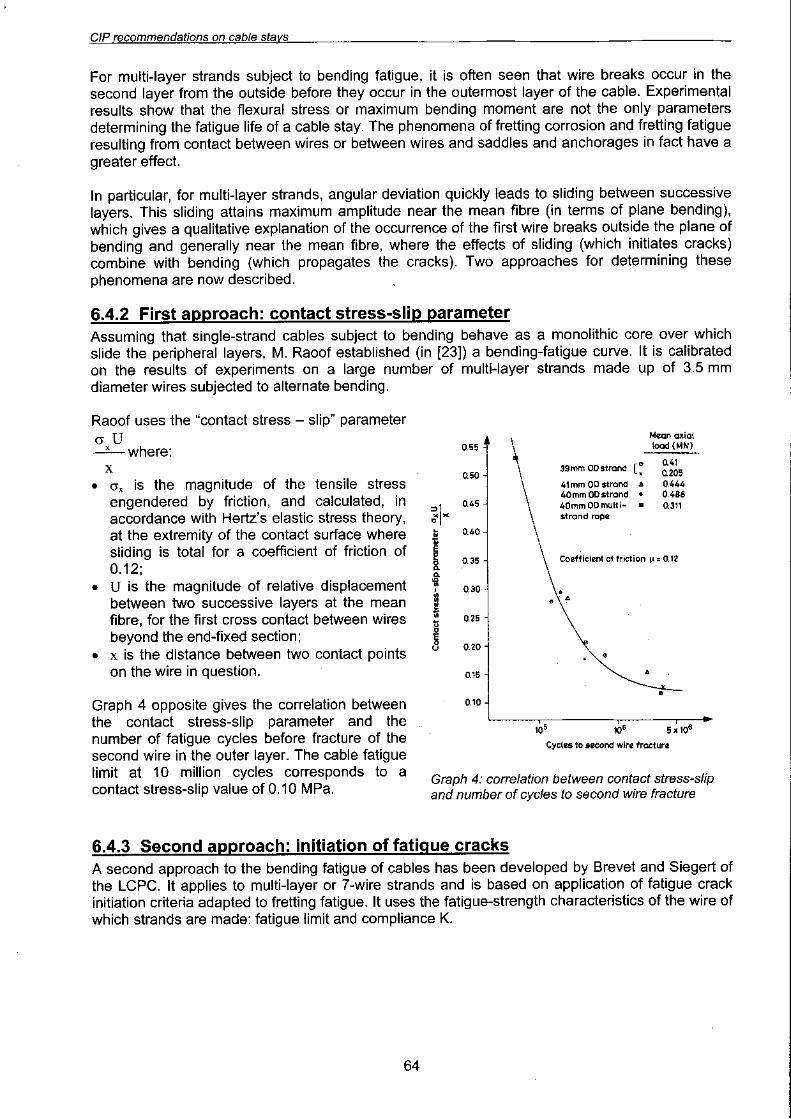
Driving research accross networks
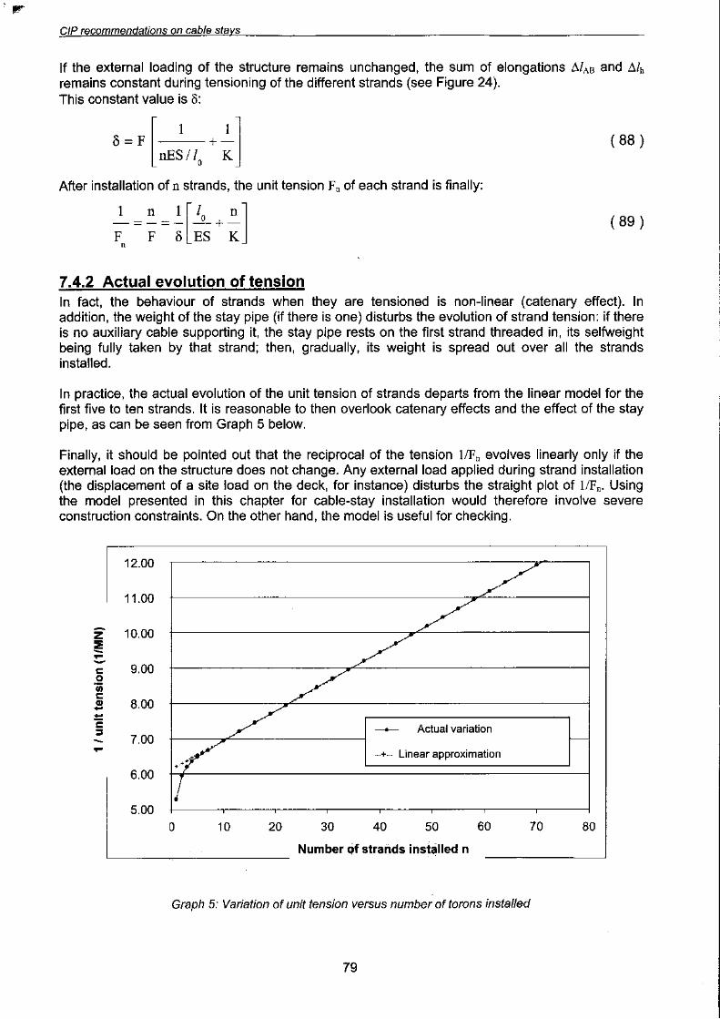
.~;
,( i,t
Recommendations of French interministerialcommission on Prestressing
~"~F~REPUBLIOUE PIANCAISE

~::L~(.,9
d..Oo~
uin
2002
Issued by the Service d'Etudes Techniques des Routes et AutoroutesCentre des Techniques des Ouvrages d'Art46, avenue Aristide Briand -BP 100 -92225 BAGNEUX CEDEX -FranceTel. 33 (0)1 46 11 31 53 -Fax 33 (0)1 46 11 3355 -www.setra.eQuipement.gouv.fr

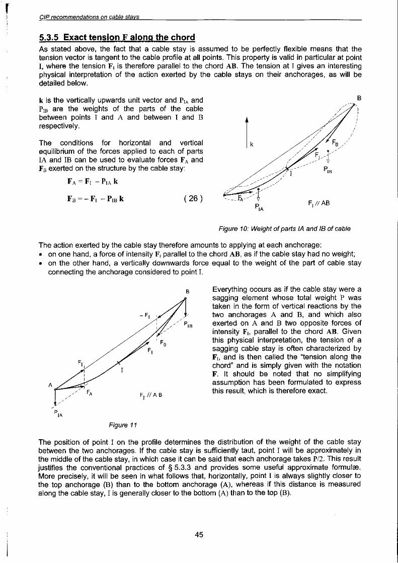
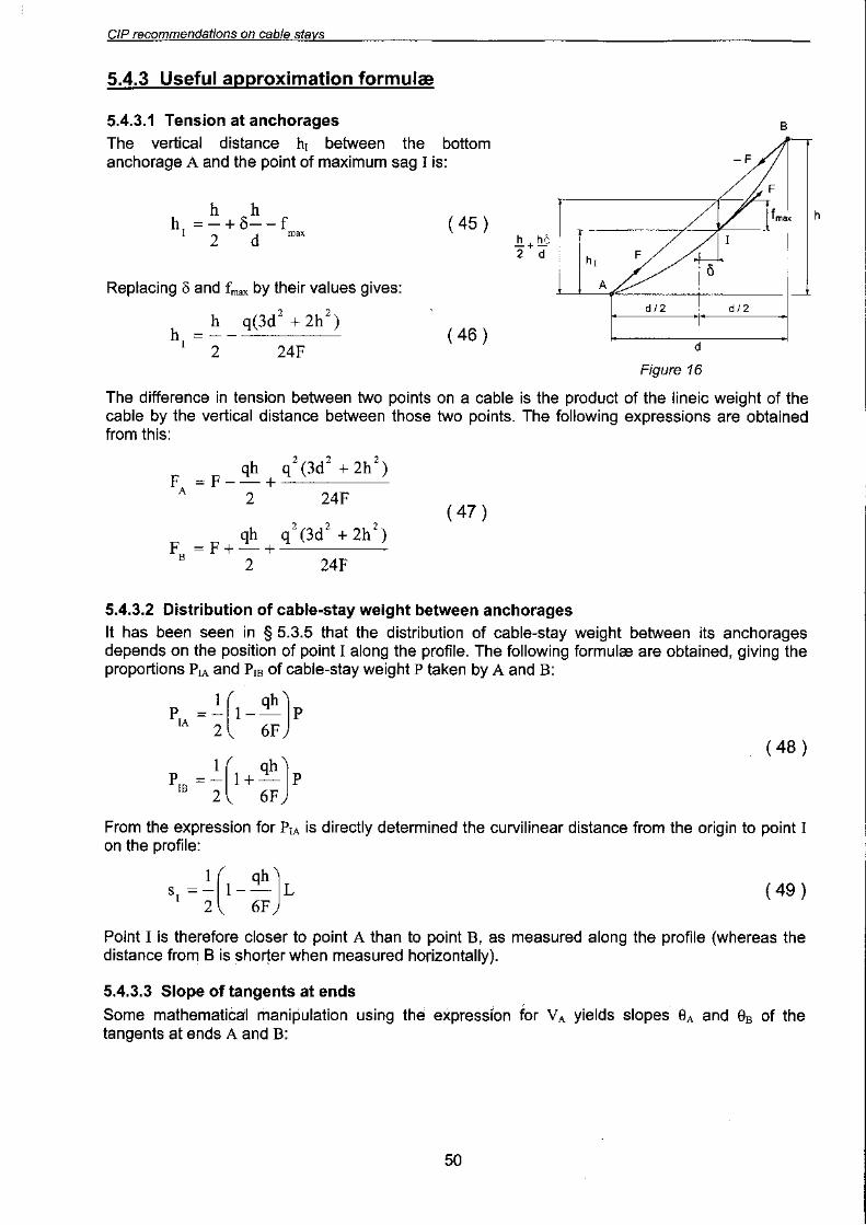
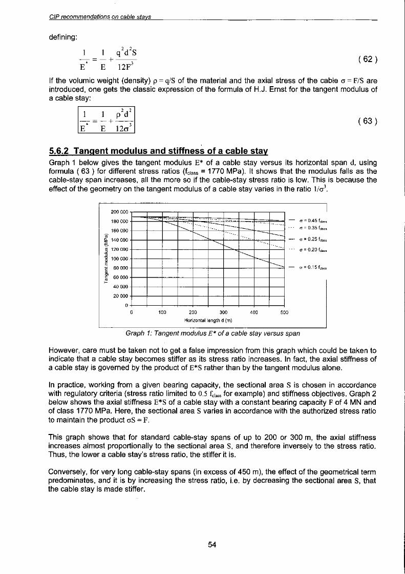
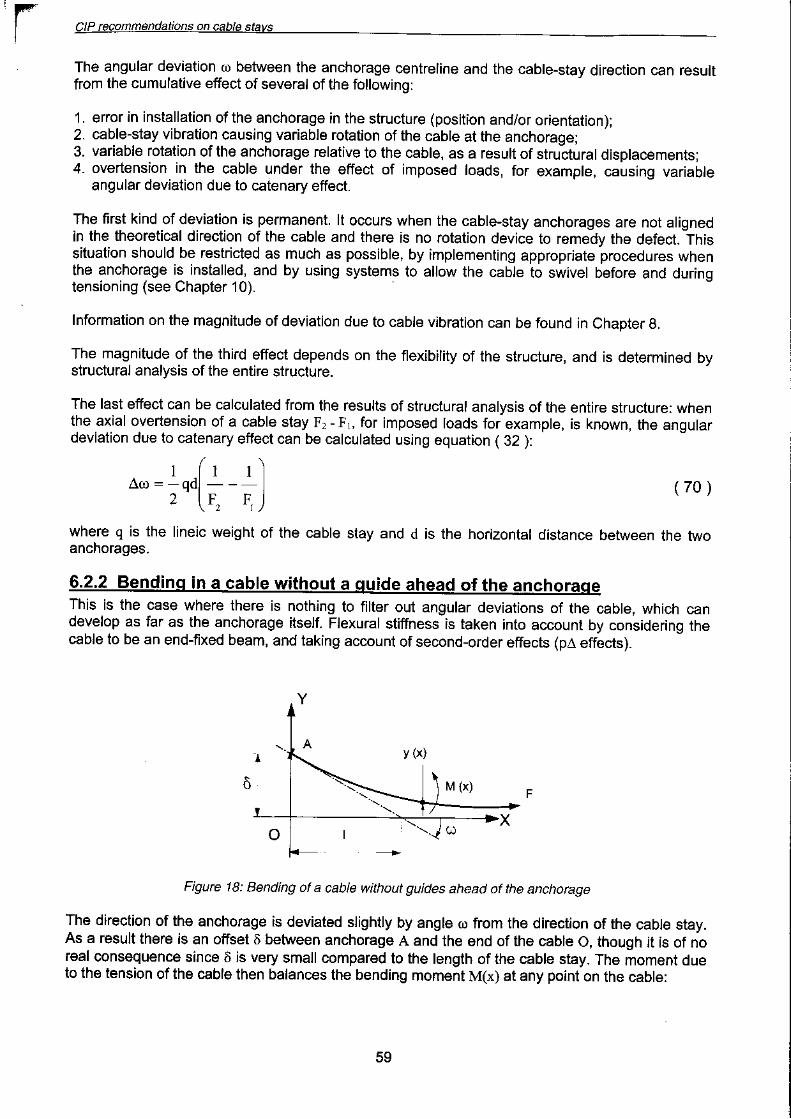
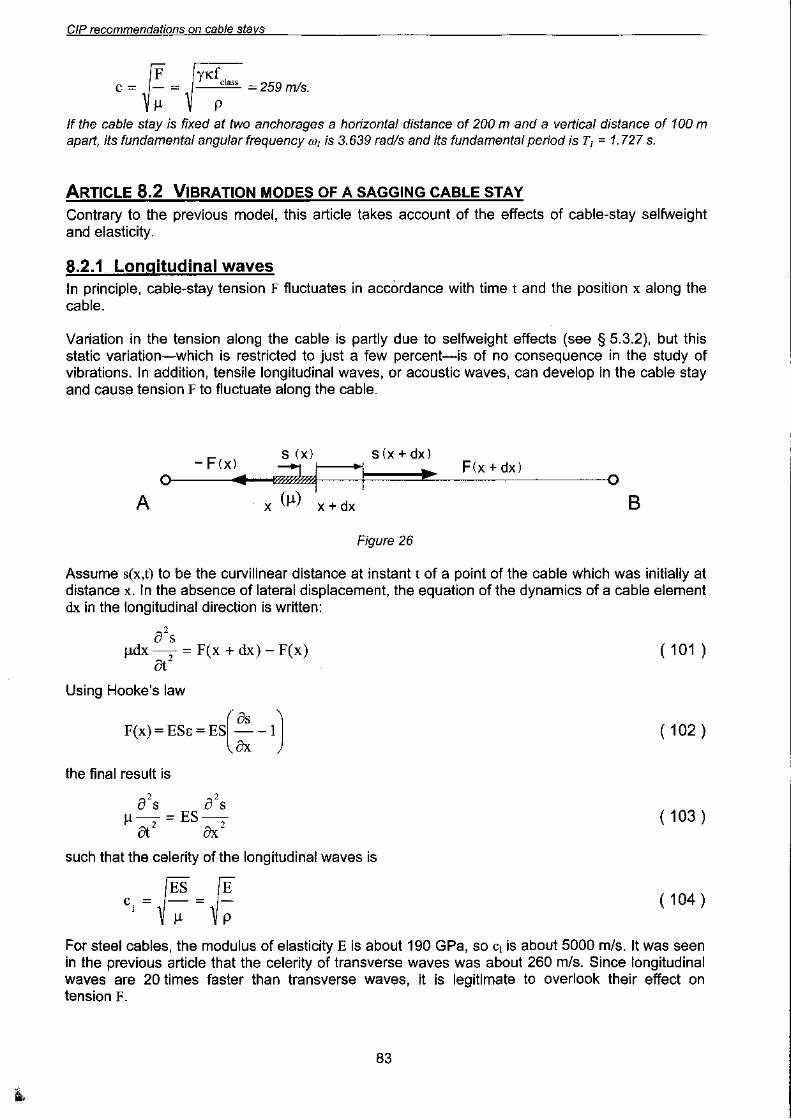
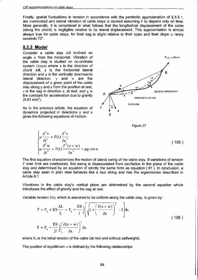
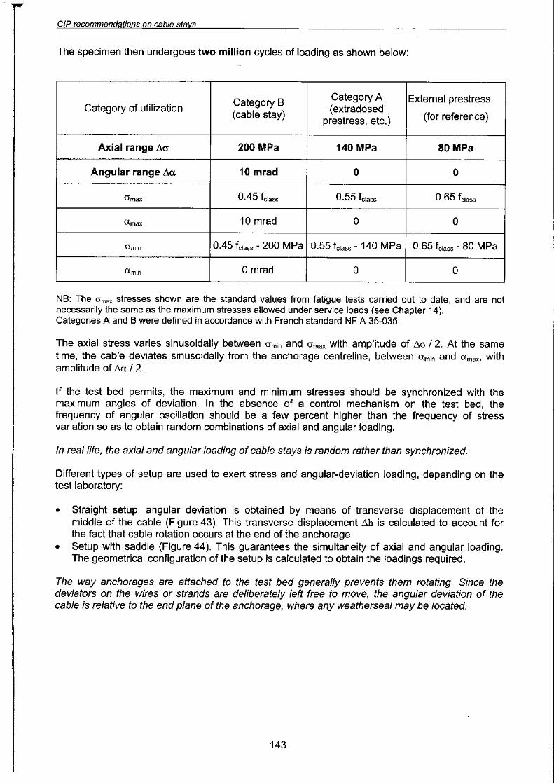
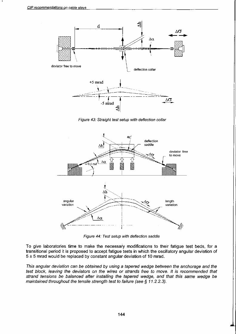
CIP recommendations on cable stavs
CONTENTS
1115
Article 2.1 Evolution of cable-stay technology Article 2.2 Operation and required qualities of cable stays
18
2022
24
Article 3.1 Inventory of cable-stay ageing factors Article 3.2 Effects of mechanical and environmental factors
Article 3.3 Choice of materials Article 3.4 Replaceability
25
2831
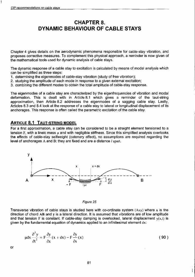
36
Article 4.1 Dynamic par.ameters of cable stays Article 4.2 Physical phenomena inducing vibration Article 4.3 Remedial actions Article 4.4 Specifications to prevent cable-stay vibration
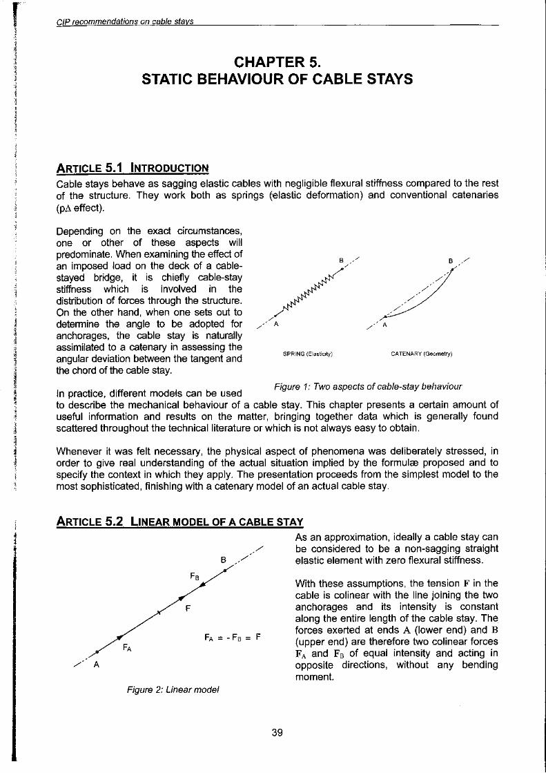
CHAPTER 5. STATIC BEHAVIOUR OE CABLE STA~
~
39
39
4247
51
53
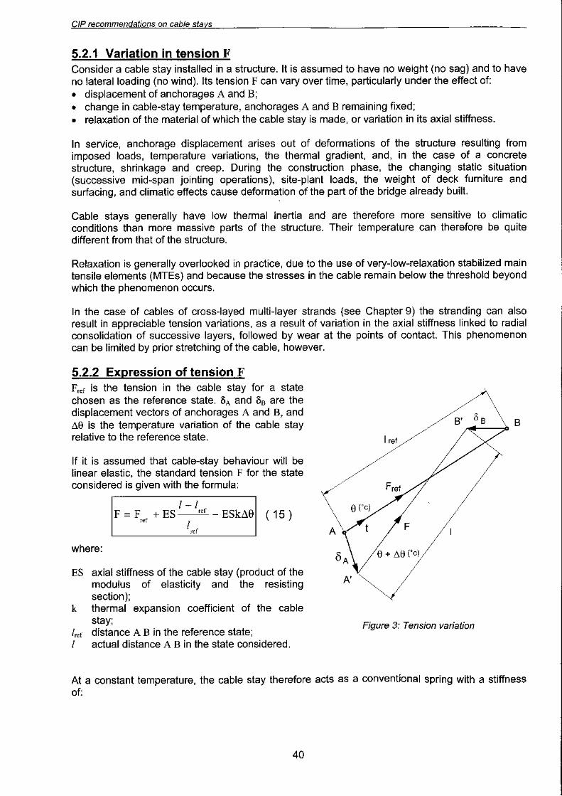
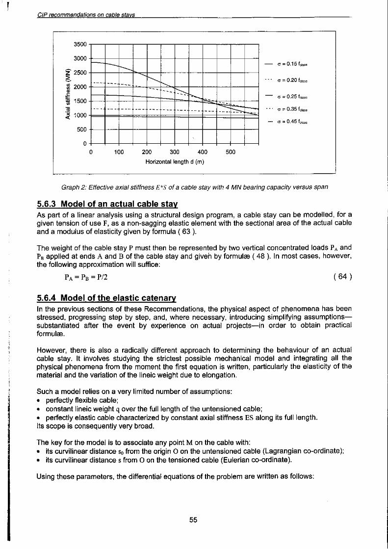
Article 5.1 Introduction Article 5.2 Linear model of a cable stay Article 5.3 Approximate effect of cable-stay selfweight.
Article 5.4 Catenary model Article 5.5 Model of inextensible sagging cable Article 5.6 Modelling a real cable stay
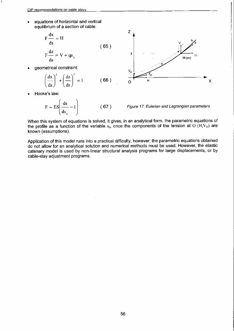
57
58
63
63
Article 6.1 Cable stay deviated at a saddle Article 6.2 Taking account of the flexural stiffness of a cable at its anchorage.
Article 6.3 Vibrations in the free length of a cable stay Article 6.4 Cable bending and durability ..""""'..."'.""'."""""""""""""".'
~PTER
7. CABLE-STAY MECHANICS DURING CONSTRUCTION 67
Article 7.1 Preloading of cable stays 67
3

CIP recommendations on cable stavs ,.
Article 7.2 Intrinsic characterization of cable-stay preloading 71
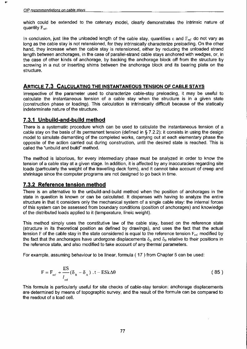
Article 7.3 Calculating the instantaneous tension of cable stays 77
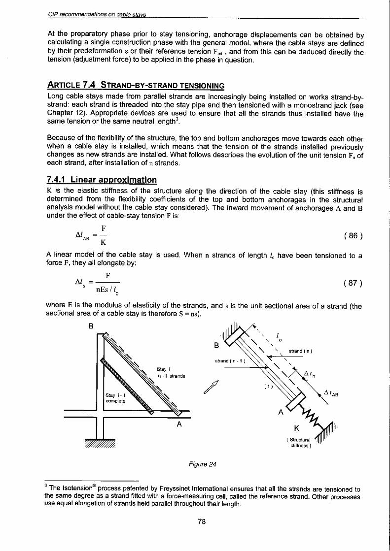
Article 7.4 Strand-by-strand tensioning 78
CHAPTER 8. DYNAMIC BEHAVIOUR OF CABLE STAYS 81--
Article 8.1 Taut-string model.. '..." ' '...'.' ' ' ' 81
Article 8.2 Vibration modes of a sagging cable stay 83
Article 8.3 Excitation by lateral displacement of an anchorage 91
Article 8.4 Parametric excitation by longitudinal displacement 93
Article 9.1 Common general requirements ."..."'.."'...' ' 99
Article 9.2 PSC category: parallel strand cable stays 103
Article 9.3 PWC category: parallel- wire cable stays 108
Article 9.4 MLS category: multi-layer-strand cable stays , 111
Article 9.5 Collective external barrier " ' ' 115
Article 9.6 Other kinds of main tensile element 119
CHAPTER 10. CABLE-STAY ANCHORAGE 121--
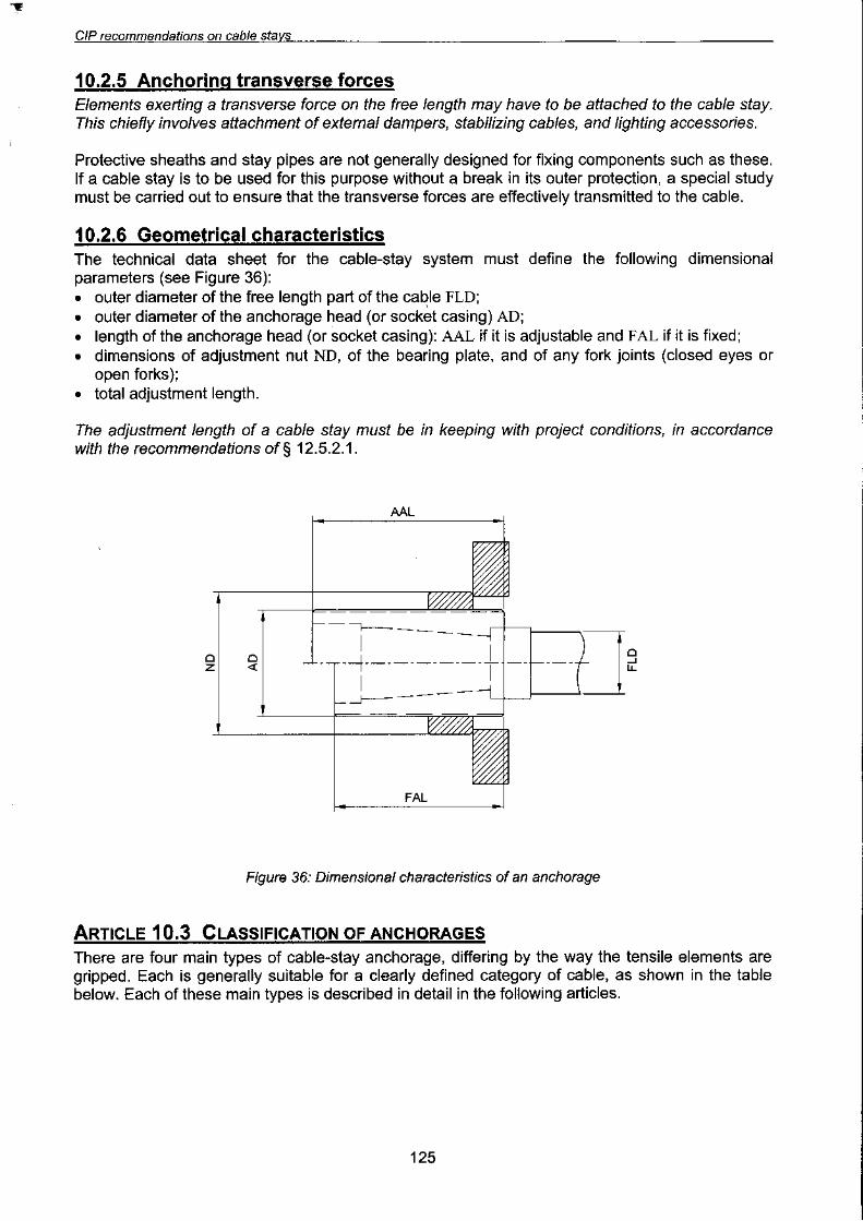
Article 10.1 Functions of a cable-stay anchorage 121
Article 10.2 General provisions common to all anchorage types 122
Article 10.3 Classification of anchorages 125
Article 10.4 Type C anchorages for parallel-strand cable .stays 126
Article 10.5 Type S anchorages for parallel-strand cable stays 130
Article 10.6 Type B or B+R anchorages for parallel-wire cable stays 131
Article 10.7 Type F+R anchorages for MLS cable stays 133
CHAPTER 11. QUALIFICATION TESTING OF A CABLE-STAY SYSTEM 139
Article 11.1 General 139
Article 11.2 Mechanical qualification of cable stays 140
Article 11.3 Qualification of cable-stay watertightness ' ' 147
CHAPTER 12. CABLE-STAY INSTAllATION 151
Article 12.1 Organizational aspects 151
Article 12.2 Supply 152
Article 12.3 Manufacture of cable stays 153
Article 12.4 Erection of cable stays 156
Article 12.5 Tensioning and adjustment 158
Article 12.6 Permanent corrosion protection 162
CHAPTER 13. MONITORING AND MAINTENANCE OF CABLE STAYS 165
Article 13.1 Principles and objectives of cable-stay maintenance 165
Article 13.2 Monitoring and maintenance 165
Article 13.3 Cable-stay adjustment 167
Article 13.4 Cable-stay replacement 168
4
CIP recommendations on cable stavs
CHAPTER 14. CABLE-STAY DESIGN AND VERIFICATION RULES 173
Article 14.1 General 173
Article 14.2 Actions and combinations of actions 173
Article 14.3 Cable-stay strength. ' 176
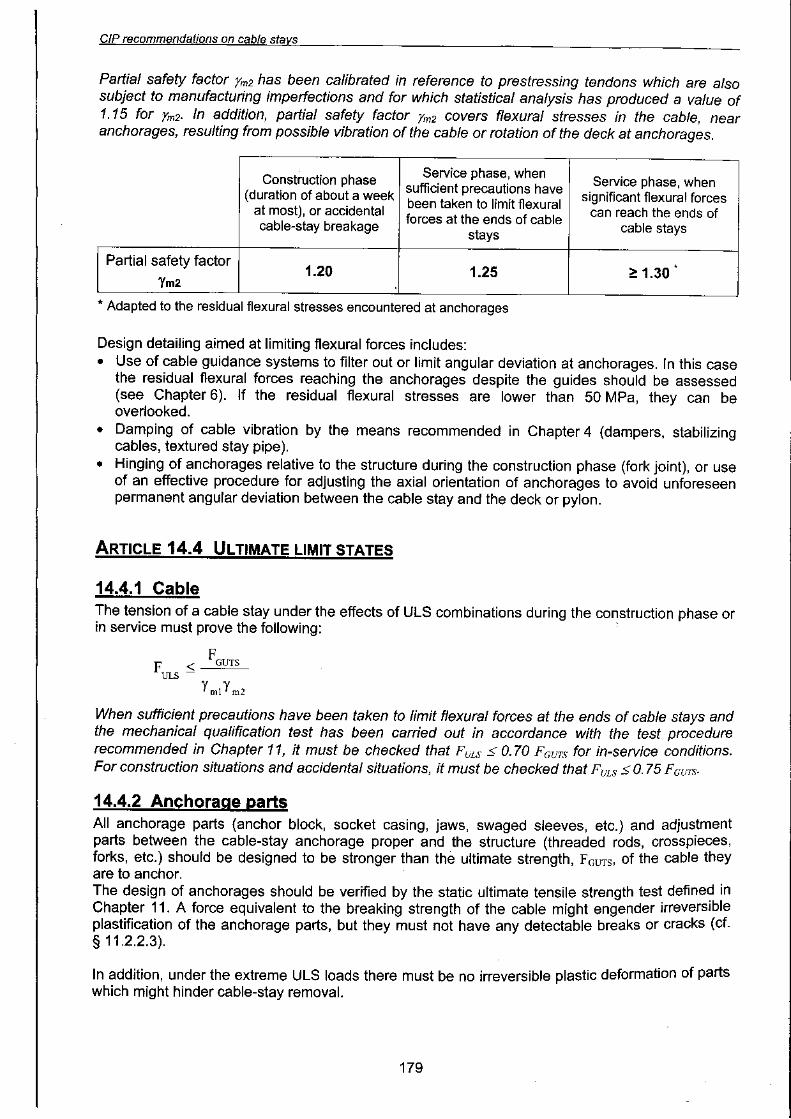
Article 14.4 Ultimate limit states 179
Article 14.5 Serviceability limit states.. 180
Article 14.6 Verifications of fatigue 182
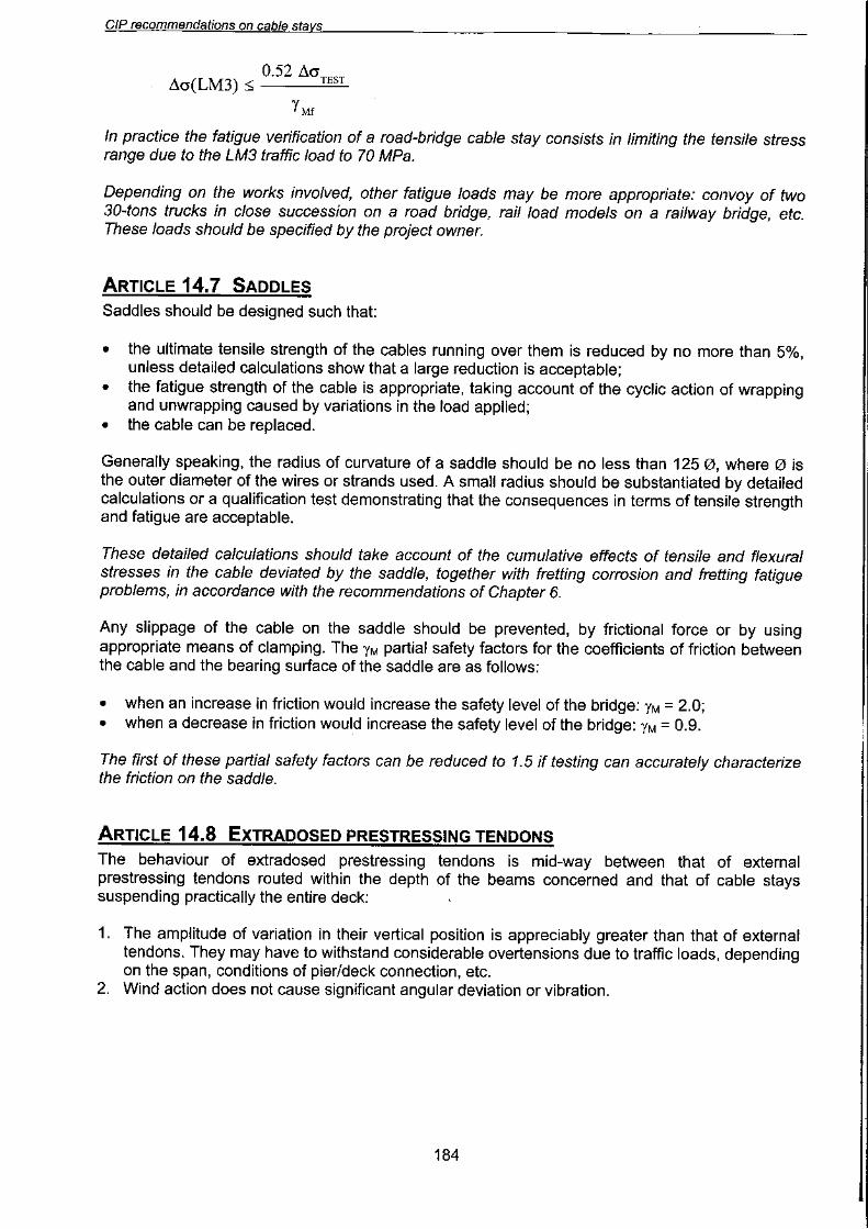
Article 14.7 Saddles 184
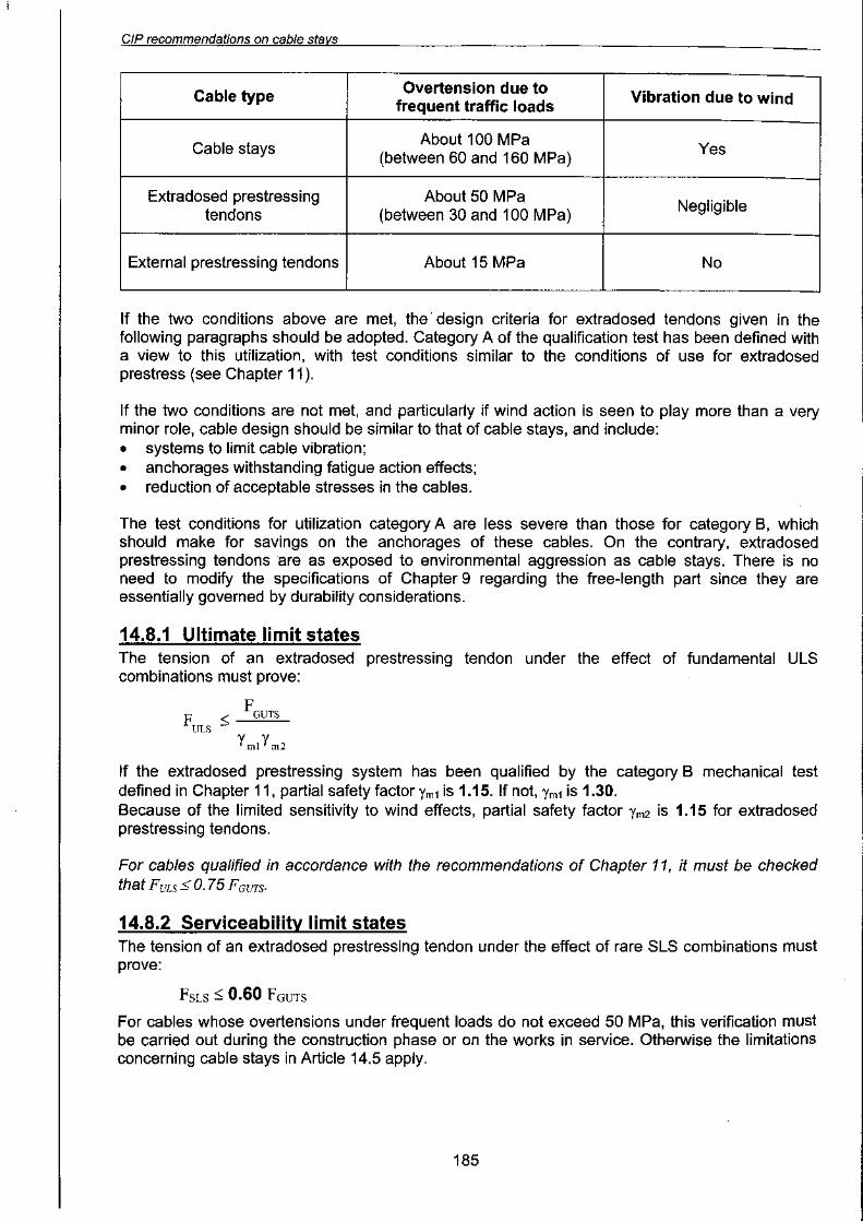
Article 14.8 Extradosed prestressing tendons 184
CHAPTER 15. REFERENCES 189
Article 15.1 Standards 189
Article 15.2 Bibliograpical references ' ' ".' ". 191
CHAPTER 16. DEFINITIONS AND NOTATIONS 193
Article 16.1 Glossary , 193
Article 16.2 Notation , 197
~

CIP recommendations on cable stays
1.FOREWORD
Early in 1997, the French Interministerial Commission on Prestressing (CommissionInterministerielle de la Precontrainte -CIP) set up a working group to study the technologicalproblems involved in cable stays and to establish an approval procedure similar to thatimplemented for prestressing systems.
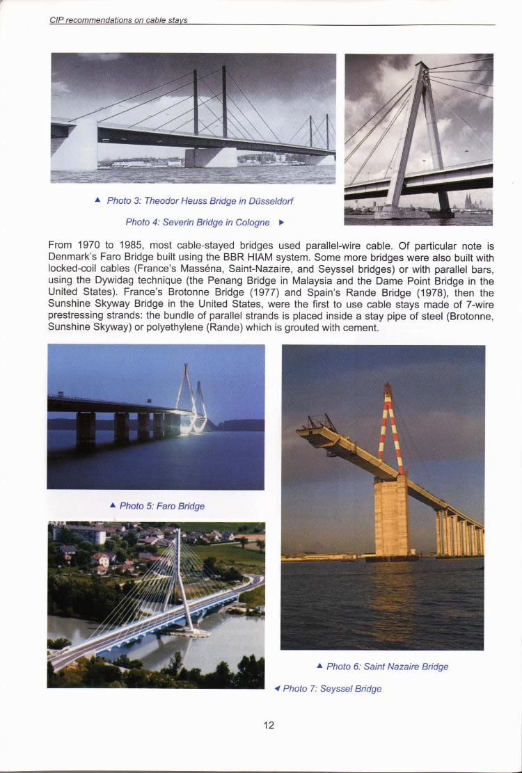
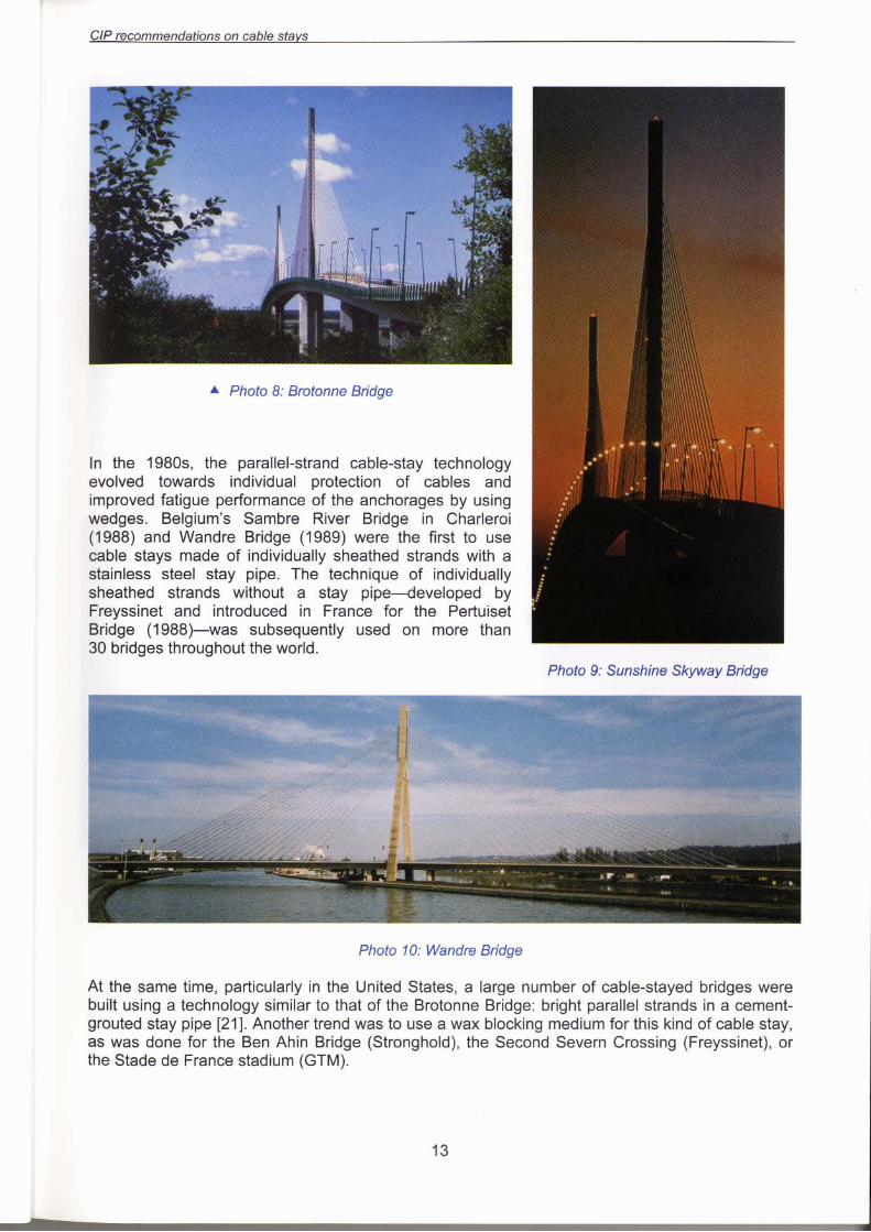
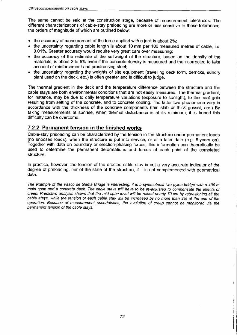
The working group drafted these Recommendations, a state-of-the-art review advising on thedesign, qualification, and implementation of cable-stay systems. It calls on the experience acquiredwith cable-stayed bridges in France and elsewhere in the last thirty years or so. This experienceincludes large cable-stayed bridges such as the Brotonne Bridge and the Pont de NormandieBridge in France, the Second Severn Crossing in the UK, and the Vasco de Gama Bridge inPortugal, but also involves a wide range of smaller bridges.
The cable technology described in these Recommendations principally concerns cable-stayedbridges, the cables of which are characterized by large variations in tension, fatigue effects, anddirect exposure to the elements. More generally, it is hoped the recommendations will be of use forall cables exposed to climatic aggression, particularly to the ties of bowstring bridges, extradosedor intradosed prestressing tendons, and cables used in any stayed civil engineering structures,such as stadium roofs, masts, etc.
On the other hand, the applications of interconnected cable networks are beyond the scope ofthese Recommendations which do not, therefore, deal with cabled spaceframe structures orsuspension-bridge technology. In addition, cable-stay saddles are addressed only in the form of afew recommendations on design, but using them is advised against, because of their effect on thedurability of cable stays and because of maintenance and replacement difficulties.
These Recommendations are broken down into four parts:.Part 1 (Chapters 2 to 8) is a review of current scientific knowledge in the matter. It takes the
form of a manual which can be referred to by designers and which substantiates the choicesrecommended in the subsequent parts.
.Part 2 (Chapters 9 and 10) describes the cable-stay systems commonly used at the moment,and gives recommendations on the technology that can achieve the greatest durability.
.Part 3 (Chapters 11 to 13) is the benchmark for approval and implementation of cable-staysystems that the CIP required.
.Part 4 (Chapter 14) presents limit-state cable-stay design rules.
Texts in standard type are recommendations.Texts in italics are comments.Texts in small type are descriptions or examples.
7

CIP recommendations on cable stavs
MEMBERS OF THE CIP CABLE-STAYS WORKING GROUP
Chairman:
Robert Chaussin (Roads Department, Ministry of Public Works)
Yves Bournand (VSL)
Alain Chabert (LCPC)
Louis Demilecamps (GTM)
Andre Demonte (ISPAT -Trefileurope)
Pierre Jartoux (Freyssinet International)
Patrick Laboure (ISPAT -Trefileurope)
Dominique Le Gall (Baudin Chateauneuf)
Benoit Lecinq (SETRA 1)
Daniel Lefaucheur (SETRA)
Claude Neant (ETIC -BBR)
The following also helped in the drafting of the Recommendations:
Michel Marchetti (Formule Informatique)
Michel Virlogeux (Consulting Engineer)
These Recommendations were co-ordinated by Jocelyne Jacob (SETRA) and Benoit Lecinq
Drawings by Philippe Jullien and Louis Risterucci (SETRA).
Translation by Alex Greenland.
Photo credits:Cover photos:1, 5, 9 (Freyssinet) -2 (Etic) -3, 4, 10 (SETRA) -6 (VSL) -7 (Fontainunion) -8 (GTM)
Photos 43, 51, 55 to 57: EticPhotos 6, 11, 35: FontainunionPhotos 8,16,17,18,20,22 to 24,26,31,33,34,41,44,45,48,54,58,59,61 to 63: FreyssinetPhotos 30, 39, 40, 46, 49, 50: GTMPhotos 13 to 15, 27 to 29: LCPCPhotos 1 to 5,7,9,10,12,19,21,25,36 to 38, 42, 47, 52, 53, 60: SETRAPhoto 32: VSL
1 Benoit Lecinq has joined the Freyssinet International group since these Recommendations were published.
8


CIP recommendations on cable stavs
Analysis of the fatigue strength of cable stays must consider two complementary factors:.pure tensile stresses due to imposed loads, whose amplitude is much greater than in the case
of prestressing tendons;.flexural stresses at anchorages, due principally to cable-stay vibration, but also to relative
deformation of the cable stables and the bridge structure. These stresses are negligible in thecase of prestressing tendons.
2.2.3 Environmental aaaressionContrary to prestressing tendons, cable stays are directly exposed to environmental aggression:rain, wind, ultraviolet radiation, freeze-thaw cycles, etc. (see Chapter 3).
2.2.4 Corollary on the desian of cable staysCable stays, which are the key factor in the stability of cable-stayed bridges, must provide the bestpossible operational guarantees. Their durability must be analyzed very rigorously at the initialdesign stage or at the stage of qualification of a cable-stay system.
However, the cable stays will remain the most vulnerable elements of the structure, and there willremain some imponderables in the appreciation of their durability. Moreover, the possibility ofdamage due to a road accident cannot be excluded.
For these reasons the design of cable stays must allow for their rapid replacement, without harmfulconsequences to the structure or serious disruption to traffic. All the protective arrangements mustguarantee that inspection, adjustment, and maintenance can be carried out to attain the requiredlifetime or to determine the need for replacement.
2.2.5 Cateaories of utilizationHigh-performance cable-stay systems are appreciably more expensive than prestressing systems.In order to restrict these extra costs for structures where the cables are less heavily loaded, asecond category of utilization has been defined (see Chapters 11 and 14).
16


O"l
.s)j:)eJ:) en6ijeJ Jo uoijemU! pUB 'UMOp)jeeJq .
~e:)eJJe~U! e4~ U! S!Jqep JO UO!~eZ!JnsseJd .
~lee~S JO ese:) e4~ U! SU!e~S ~SnJ 'S!Jqep JO UO!~ep!XO .
~S~U!Or O~U! S!Jqep JO UO!~eJ~eued pUB I\eld peSeeJ:)U! .
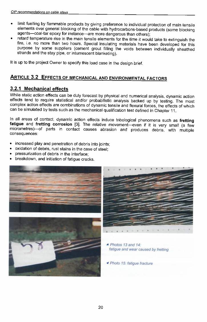
:S8~U8nb8SUO~8ld!tlnw 4t!M 'S!Jq8p S8~npoJd pUB UO!SeJqe S8Sne~ t~etUO~ U! stJed jO-(S8Jt8WOJ~!WM8j e) Ilews AJ8A S! t! j! U8A8-tU8W8AOW 8A!te18J 841 "[£] UO!SOJJo:> 6u!~~aJI pUB an6!~el6u!~~aJI se 4~ns eU8WOU84d le~!5010q!Jt 8~npU! St~8JJ8 UO!t~e ~!WeUAp 't~etuo~ jO Se8Je lie UI
.~ ~ Je~dB4~ U! peu!Jep ~se~ UO!~B:)!J!IBnb IB:)!UB4:)eW e4~ SB 4:)ns s~se~ Aq pe~BlnW!S eq UB:)
4:)!4M Jo s~:)eJJe e4~ 'se:)JoJ IBJnXelJ pUB el!SUe~ :)!WBUAP JO SUO!~BU!qWO:) eJB s~:)eJJe UO!~:)B Xeldwo:)~SOW e41 .6u!~se~ Aq dn pe)j:)Bq S!SAIBUB :)!~S!I!qBqOJd JO/PUB IB:)!~S!~B~S eJ!nbeJ O~ pue~ s~:)eJJe
UO!~:)B :)!WBUAP 'S!SAIBUB IB:)!JeWnU pUB IB:)!SA4d Aq ~SB:)eJOJ Alnp eq UB:) s~:)eJJe UO!~:)B :)!~B~S el!4M
sJ:>a.ua le:>!Ue4:>aw ~ "Z"£
S~Ol~'V'~ 1'V'lN3WNO~II\N3 ON'V' 1'V'~IN'V'H~3W ~O Sl~3~~3 Z"£ 31~1l~"V
"je!Jq UD!Sep e4~ U! ese~ peal S!4~ AJ!~eds o~ JeUMO ~~eroJd e4~ o~ dn S! ~I
"(6u!Je)juelq Jue::>seWmU! JO 'ed!d !\eJs e4J pUB SpUeJJspe4Jee4S !\llenp!l\!pU! UeeMJeq SP!OI\ e4J 6U!II!J JnoJ6 Juewe::» SJe!lddns ewos !\q esodJndS!4J JOJ pedOlel\ep ueeq el\e4 Sle!JeJew 6u!JelnSU! le!::>eds "SJn04 OMJ ue4J eJOW OU 'eO! 'eJ!Je4J 4S!n6u!Jxe OJ e)jeJ plnoM J! ew!J e4J JoJ sJuewele el!SueJ u!ew e4J U! es!J eJmeJedweJ pJeJeJ
~(SJe4Jo ue4J snoJe6uep eJOW eJe-e::>ueJsu! JoJ !\xode JeJ-leo::>-sJue6e6u!)j::>0Iq ewos) sJ::>npoJd peseq-suoqJe::>OJp!\4 4J!M elqe::> e4J Jo 6u!)j::>°lq leJeue6 Jel\O sJueweleel!SueJ u!ew Jo uo!J::>eJoJd lenp!l\!pu! OJ e::>ueJeJeJd 6u!I\!6 !\q sJ::>npoJd elqewwelJ !\q 6u!llenJ J!W!I
..sAelS 8/qe:J UO suO!lepU8wwo:J8J d/:J


II
.pe6pnf eq ue~ slesodoJd e4J 4~!4M uo uo!JewJoJu! ewos ep!AoJd seldwexe 6U!MOIIOJ e41. '0 ~pUB 6 sJeJde4~ U! peU!Jep eJe enb!U4~eJ 6u!"eJS-elqe~ 4~ee OJ ~!J!~eds Seld!~u!Jd le~!6oI0U4~eJ e41.
.At!l!qeJnp peJ!Sep e4t eAe!4~e °t UO!telnWJOj le!~eds pue lUewteeJttee4 JO e~ejJns 'senb!U4~et uo!t~nJtsuo~ osle tnq 'st~eJJe uo!t~e le~!Ue4~eW 4t!M e~UepJO~~eU! peU!WJetep AileJeue6 eJe 4~!4M sle!Jetew ~!Seq e4t AIUO taU SUJe~uo~ sle!Jetew jO e~!04~ e41
SlVI~31 Villi ::10 3~IOH~ tOt 31~ll~"V
"SI!ej alqea a411!lUn ssaJ60Jduea UO!soJJoa laa1s 'an6!lej pUB 6u!lJaJj UO!SOJJOa sJapua6ua 1noJ6 a41 U! s)faeJa jO "6u!41eaJq,, aaU!S "g
"lnoJ61UaWaaa41 U! S)faeJa a6e)fU!J4S alqeHAaU! a41 etA laa1s a41 4aeaJ pUB Ae1s alqea a41 a1eJ1aUad ua41 uea Ja1eM "p'
'an6!lej 01 anp a1e6edoJdAI1uanbasqns II!M 4a!4M 6u!)faeJa aaejJns asnea uea (lnoJ6 1uawaa 4HM 6u!)faolq jO asea a41 U! uo!suedxa
paU!eJ1SaJ 'Ae1s alqea a41 jO aJnXalj) SaSSaJ1S aa!/\Jas pUB SaSSaJ1S lenp!SaJ asa41 jO UO!leU!qwoa a41 "f;
"pUnOMUn S! H ua4M lea!la4 41ea4s a41 6u!)few '(fe!Ja1ew a41 jO "Nowaw,,) pasnea S! I!oaa41 jO uO!lewJojap 1UaUewJad alq!SJaAaJJ! 'papaaaxa S! 3dOH a41 jO (lU!od PlatA) HW!I a!lSela a41 ua4M "Z
"6u!puaq pUB UO!SJ01 jO UO!leU!qwoa e 01
1aa!qns S! 41ea4s a41 pUB 'UO!SJ01 u!eJjaa e dn slas 6u!pUeJ1S J!a41 'punoM ale salqea pa1ea!JqejaJd ua4M "~:SJeaA 0 ~ AtUO 1noqe Jaye 'lnoJ61UaWaa 4HM pa)faolq sAe1s alqea uo pa/\Jasqo A601041ed a41 jO a,dwex3
'J8l8WB!P B IIBWS DOl jO SWnJp °lUO pUnOM
S8d!d ABlS 8U81A4l8AIOd p8lBlnwJOj AIJ8dOJdW! Aq P8l::>8l0Jd SABlS 81qB::> P8lB::>!JqBj8Jd Uo In::>::>o
UB::> II .UMOU)f 118M MOU S! SU!j810AIOd jO (:)S3) 6U!)f::>BJ::> SS8JlS IBlU8WUOJ!AU8 jO UOU8WOU84d 841
~uaWUOJ!AUa a4~ pue s~u!eJ~suo:> lenp!sa~ G£'G£
.se6P!Jq peAe~s-elqe~ JO selPpes eLl~ U! Jn~~oue~ swelqoJd Jel!W!S .pesn ueeq sell ~ue6e 6u!)j~Olq ou ueLlM '~~e~uo~ ~u!od e)jew SeJ!M peAel-SSOJ~ JO SJeAel eJeLlM 'selqe~ pueJ~s JeAel-!~lnW JO eJnl!eJ JO sesne~ eLl~ JO euo S! S!LI~ 'se6p!Jq uQ
SAelS a/qea uo Suo!lepuawwoaaJ d/:J


9G
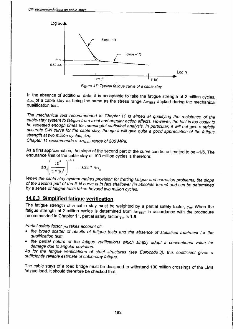
:Ae~s elqe~ e jO 9 ~UeWeJ~ep ~!WLI~!Je601
Aq peU!jep s! SUO!~ell!~SO eeJj e/\!SSe~~ns OM~ jO Sepn~!ldwe jO o!~eJ jO WLl~!Je601 eLl~ 'AI leU!::!
:se pau!Jap s! ~ o!~eJ6u!dwep a4~ 'l\~uanbaJJ Jeln6ue le~uawepunJ s~! ~(I) pue I\e~s alqe~ a4~ Jo ssew ~!au!1 a4~ s! 11 JI
dump'~I he d
:(£"g al~!~'r;f aas) A ~ue~suo~ 5u!dwep sno~s!J\ e WOJJ pallapow aq ue~ 4~5ual ~!un Jad a~JoJ 5u!dwep
a4~ 'S~!WeUAp Jo suo!~enba a4~ ul 'sJa~aweJed leJaJ\as Aq paz!Ja~~eJe4~ S! pue 'sa5eJO4~UeS~! Jo JO Ae~S a4~ Jo s~uauodwo~ a4~ uaaM~aq UO!~~!JJ leUJa~U! Aq pasne~ S! 5u!dwep Ae~s-alqe~
DU!aWea Z. ~ 'p
xe-J..-=
MO/Jlte
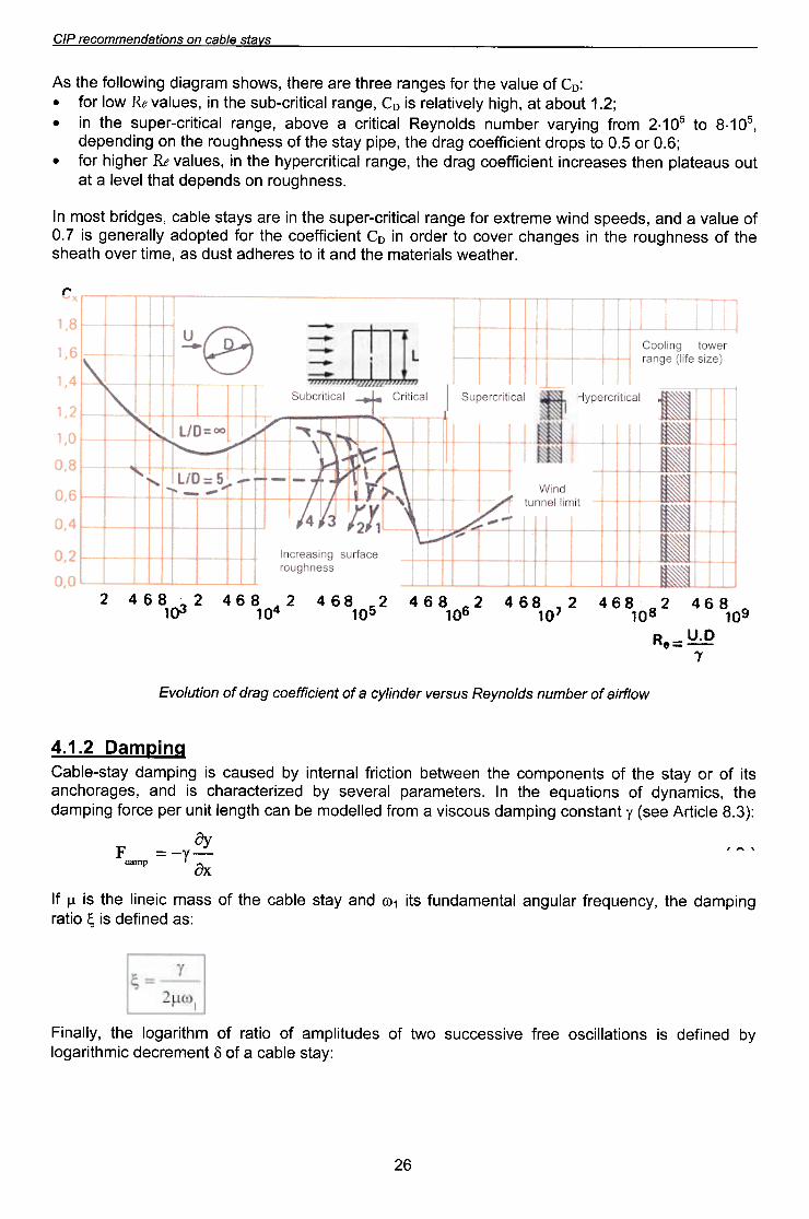
)0 Jeqwnu sP/ou/ie~ SnSJe/l JepUt//ia e )0 lUetatJjeoa 6eJp )0 UOtln/o/l3
,(.Q":'n = e ij
SOlS 9 t1SOL
l 89tOl gOl
Z' 89~ Z 89~
-f
gOLl 89t
t'OlZ 89'
toOLl B9vl
Z'o
---;
-~~t7'O
ss8ulj6noJ8:)eJjnS 6U!Se8J:)ul
:1~ r /~I"- ~ J!W!llauunJ
PU!M+-
9'0=m
:::-.;;-;...;'.t1 9 = a/_~"8'0
O'l
~'l
~"~. 11
~ j~=O/1
le:>!I!J:>J8dAHle~!I!J~Jadnsle:J!J!J:J "t- le:J!J!J:Jqns't
@n'\.
9'L
B'l
:)
.Je4~eeM Sle!Je~eW e4~ pUB ~! O~ SeJe4pe ~snp se 'eW!~ JeAO 4~ee4Se4~ }O SSeU46noJ e4~ U! se6ue4~ JeAO~ O~ JepJO U! OJ ~Ue!~!JJeo~ e4~ JO} pe~dope AileJeue6 S! L.O}O enleA e pUB 'speeds PU!M eweJ~xe JO} e6ueJ le~!~!J~-Jedns e4~ U! eJe sAe~s elqe~ 'se6P!Jq ~sow UI
.sseU46noJ uo spuedep t84t leAel 8 t8
tnO Sn8et81d Ue4t SeS8eJ:)U! tUe!:)!JJeo:) 68Jp e4t 'e6U8J 18:)!t!J:)JedA4 e4t U! 'Sen18A ITH Je46!4 JOJ .~9.0 JO S'O °t SdOJp tUe!:)!JJeo:) 68Jp e4t 'ed!d A8tS e4t JO SSeU46noJ e4t uo 6u!puedep
'gO ~.9 °t gO ~.z WOJJ 6U!/\J8A Jeqwnu SPIOUAe~ 18:)!t!J:) 8 eAoq8 'e6U8J 18:)!t!J:)-Jedns e4t U! .
~Z' ~ tnoq8 t8 '46!4 AleA!t8leJ S! oJ 'e6U8J 18:)!t!J:)-qns e4t U! 'Sen18A ITH MOl JOJ .
:oJ JO enl8A e4t JOJ Se6U8J eeJ4t eJ8 eJe4t 'SMO4S W8J68!P 6U!MOIIOJ e4t S'v'
SAelS 8/qe.? UO suoflepu8wwo.?8J d/O
Z£
.s~u!od 6U!MOIIOJ e4~ o~ p!ed eq Plno4s uo!~ue~~e 'SWe~SAS Ae~s-elqe~JO SJe!lddns e4~ Jo S~46!J AJe~e!JdoJd AileJeue6 eJe sJedwep ese4~ Jo 6u!~eJ pUB u6!sep e4~ 46nO4~1V'
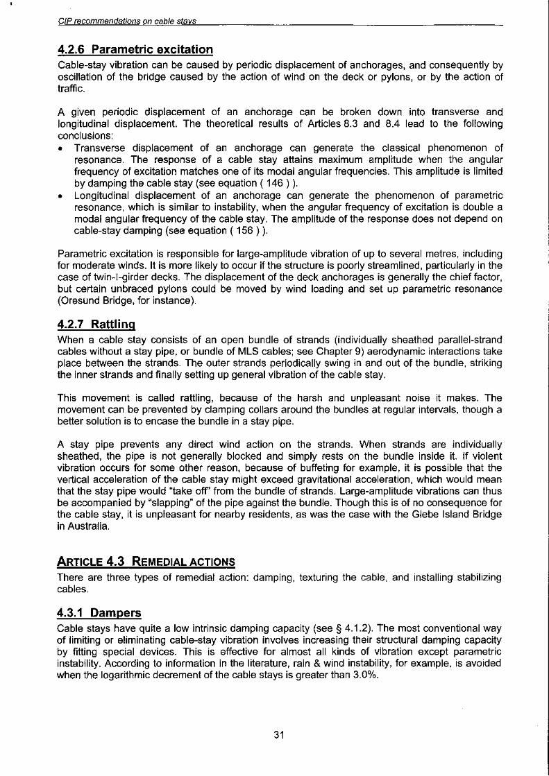
'e6p!J8 elleAeppn elj~ uo se 'SP!IOS OM~ ueeM~eqUO!~:)!J! f\Jp JO 'se6p!Jq eeljoes JO 'punseJO 'ewe~ ep o:)se/\ elj~ uo se 'UO!~:)!J! SnO:)S!AJO (eueJdoeu pe~elnwJo! Alle!:)eds) le!Je~ew 6u!~ed!ss!p e!o UO!~O~S!P elj~ esn sJedwep leuJe~UI
"( euo JeMOI elj~ AlleJeue6) se6eJolj:)ue elj~ !O Jelj~!e Jeeu 'eJn~:)nJ~s elj~ o~ AIP!6!J pelj:)e~~e eqn~lee~s e pUB elqe:) elj~ ueeM~eq pe:)eld eJe Aelj~ pUB 'pedeljs-6u!J eJe eselj~ ~sJadwep leUJa~UI
.
sn6el ell) JeAO e6p!J8ewe£) ep oase/\ uo Jedwea :0'(; O)OLld
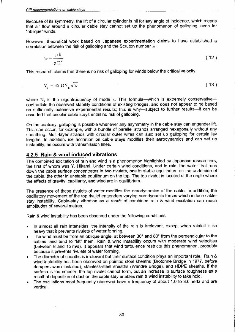
a6P!J8 auuoJOJ8 uo sJadwea :6 ~ °JOl/d
e6pfJB efpueWJON ep luod eLll uo sJedwea :8 ~ °loLld
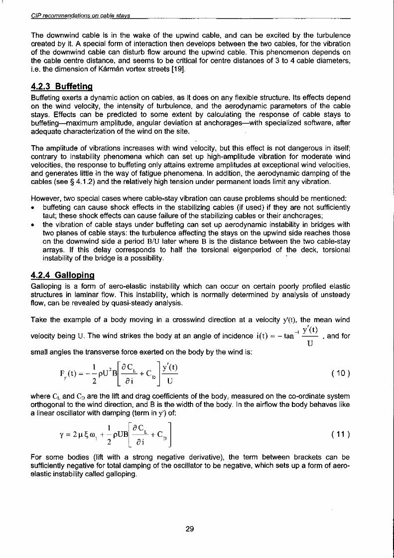
"e6p!J8 e!puewJON ep ~uod e4~ uo se 'Jel\el Jelnpued e Jo pue e4~ ~e JO 'e6p!J8 euuo~oJ8 e4~uo se 'I\e~s e4~ uo 1\1~~eJ!p 'sJ!ed U! pelle~SU! eq ue~ l\e41 .se6eJ04~Ue e4~ Jeeu 'elqe~ e4~ uoe~JoJ 6u!dwep eSJel\sueJ~ e 6u!~exe se~!l\ep ~!lneJpI\4 I\IIeJeue6 eJe ese4~ ~sJadwep leuJa~x3 .
:sJedwep Jo SPU!)j leJel\es eJe eJe41
S/lelS e/qe:J uo suoflepuewwo:JeJ d/::J
P£
')f~ap a4J uo PU!M OJ anp %917 AIUO 4J!M 'sAeJs alqe~ a4J uo 5eJp OJ anp S! 'SUOIAd a4J
oJU! pax!J S! J! aJa4M ')f~ap a4J U! Juawow s!xe-le~!JJal\ a4J Jo %99 'aldwexa JoJ 'a5p!J8 a!puewJoNap JUOd a4J JO::l 'JoJ~eJ JueJapuodaJd a4J sawo~aq sAeJs alqe~ Jo aueld a4J uo uo!J~e PU!M 'uo!J~asSSOJ~ sJ! Jo 5u!U!IWeaJJs al\!J~a.!Ja Aq pa~npaJ aJe )f~ap a4J uo sa~JoJ 5eJp JI 'sa5p!Jq paAeJs-alqe~ueds-5uol JoJ UJa~uo~ JueJJodw! ue S! Jua!~!.!Jao~ 5eJp a4J 5u!~npaJ Je4J pa/\Jasqo aq Plno4s JI
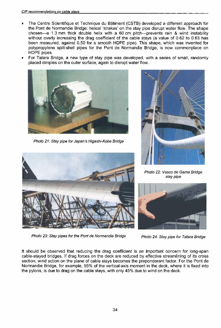
e6P!Jg BJBIB.! JOj ed!d ti"BIS :f7l OIOl/d86P!J8 8!pUeWJON 8p 1uod 841 JOj s8d!d ,{e1S :CZ °1o4d
adfd ,{elsa6pfJfj ewef) ap o.:>se;\ :ZZ olo4d
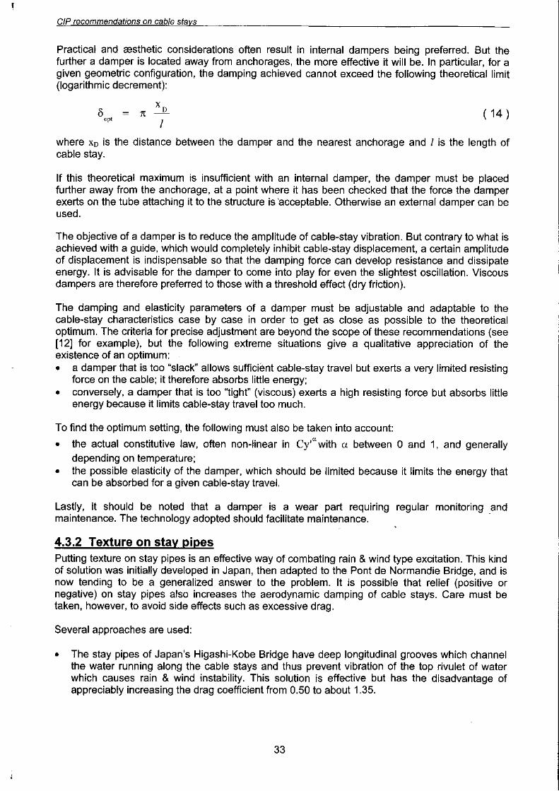
a6p!J'd aQO){-!4Se6!H s,ueder JOj ad!d ,{elS : J."l 0104d
"MOIJ J8JeM JdnJs!p OJ u!e6e '8~eJJnS J8JnO 84J uo S81dW!p p8~eldI\lwopUeJ '1IeWS JO S8!J8S e 4J!M 'p8dol8A8p SaM 8d!d l\eJs Jo 8dl\J M8U e '86P!J8 eJeJe1 Jo.::l
"s8d!d 3dOHuo 8~elduowwo~ MOU S! '86P!J8 8!puewJoN 8P Juod 84J JoJ S8d!d 1184S-J!lds 8U811\doJdl\IodJoJ P8JU8AU! saM 4~!4M '8de4S S!41 '(8d!d 3dOH 4JoOWS e JoJ 09'0 Jsu!e6e 'p8JnSe8W u88q
se4 £9'0 OJ 19'O Jo 8nleA e) sl\eJs 8lqe~ 84J JO JU8!~!JJ80~ 6eJp 84J 6U!Se8J~U! I\IJ8AO JnO4J!MI\J!I!qeJsU! PU!M ~ u!eJ SJU8A8Jd-4~J!d w~ 09 e 4J!M X!184 81qnop )j~!4J ww £' ~ e-u8so4~8de4s 841 'MolJ J8JeM JdnJs!p 8d!d l\eJs 84J uo ,s8)jeJJs, le~!184 :86p!J8 8!puewJoN 8P Juod 84JJoJ 4~eoJdde JU8J8JJ!P e p8dol8A8p (818:)) Ju8W!J~8 np 8nb!U4~81J8 8nb!J!Ju8!~8 8JJU8:) 841
..SJ\elS 8/qe.? UO suoflepu8wwo.?8J d/:J

9£
86pfJfJ 8fpuewJoN 8P 1Uod 81/1 UO uOf1a8uuoa 8/qea 6UfZf/fQe1SjAe1S :9~ 010l/d
86P!Jg 8!pUeWJON 8p Juod 84J uo S8/qea 6u!z!/!qeJS :gZ °Jo4d
'sepow uo!~eJq!1\ esJel\sueJ~ uo ~~eJJe pe~npeJ f\lqeJep!suo~ e el\e4 f\e4~ Jel\eMOH .swelqoJde~ueuoseJ ~!J~eweJed u!e~e~ 6u!~uel\eJd JoJ elqe~!nS f\IJeln~!~ed eJoJeJe4~ eJe selqe~ 6u!Z!I!qe~s
'sepow uo!~eJq!1\ le~!~el\ .~~e '4~U!U '4~X!S 'PJ!4~ e4~ ~nq lie ~!q!4U! II!M f\e~s elqe~ e Jo ueds e4~ 6uOIef\eM e4~ Jo SPJ!4~ OM~ pUB PJ!4~ euo pe~eld selqe~ 6u!Z!I!qe~s OM~ :sf\e~s elqe~ Jo uo!~eJq!1\ le~!~al\
Jo sepow u!e~e~ ~!q!40Jd f\e4~ ~e4~ S! uo!~~eJ~~e u!ew J!e4~ 'pue4 Je4~0 e4~ uo .~~eJJe 6u!dwep eel\e4 oo~ f\e4~ sselun 'f\~!I!qe~SU! PU!M ~ u!eJ 6u!~uel\eJd U! sJedwep ue4~ el\!~~eJJe sse I eq o~ uel\oJdel\e4 f\e4~ ~nq '(~~eroJd e6p!J8 e!puewJoN ep ~uod e4~ JoJ ese~ e4~ saM S!4~) peu6!sep f\le~e!JdoJddeJ! '6u!dwep leUO!~!ppe eP!l\oJd asIa ue~ pUB sf\e~s elqe~ Jo f\eJJe e4~ ueJJ!~s selqe~ 6u!Z!I!qe~s
.sl\e~s elqe~ e4~ Jo spo!Jedue5!e e4~ I\J!POW I\leA!~Ue~sqnsO~ eJoJeJe4~ SeM selqe~ 5u!Z!I!qe~s e4~ Jo esodJnd e41 ')j~ep e4~ Jo sepow leJnxelJ e4~ Jo~e4~ se ewes e4~ 1\145noJ seM sl\e~s elqe~ e4~ JO uo!~eJq!A JO po!Jed le~uewepunJ e4~ ~e4~ pe~eln~le~ueeq pe4 ~! eJe4M e5p!J8 e!pueWJON ep ~uOd e4~ uo pesn osle seM we~sl\s elqe~-5u!Z!I!qe~s
'if .sl\e~s elqe~ peUU!M~ JO 5u!dolle5 e)jeM ~ueAeJd O~ ueder U! pesn ueeq osle eAe4 l\e41 .selqe~5uOI JO uo!~eJq!A e4~ ~ueAeJd O~ ')jJewueo U! e5p!J8 OJe::l e4~ uo pesn ~SJ!J eJeM selqe~ 5u!Z!I!qe~s
uo!}eJq!J\ l.e}S-8Iqe:) JO SPU!)! 8WOS }U8J\8Jd ue:) s8lQe:) 5U!}:)8UUO:)J8}U! 5u!lle}SUI
salqe:> tjU!Z!I!qe~s £"£"P
SJ\elS a/qea uo SUO!lepuawwoaaJ d/:J


99
pU8JjS
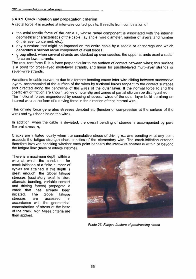
6U!SS8JjS8Jd jO 8JnjQ8Jj 8n6!j8.::/ :Ll' Oj04d
'pe!ldde ue4~eJe e!Je~!J~ ses!lAJ UO/\ .>I~eJ~ e4~ Jo
eseq e4~ ~e sseJ~s Jo uo!~eJ~ue~uo~le~!J~ewoe6 e4~ 4~!M e~UepJO~~eU! pessesse eJe SeSSeJ~S
en6!~eJ leqol6 e41 .pe~e!~!u!ueeq ApeeJle se4 ~e4~ >I~eJ~e e~e6edoJd (se~JoJ 6U!A!Jp pUB
~~e~uo~ elqe!JeA '6u!pueq e~eUJe~le'UO!SUe~ le!Xe AJO~ell!~SO) SeSSeJ~Sen6!~eJ leqol6 e4~ '46noue ~eeJ6S! 4~dep S!4~ JI .peU!e~~e eJe Sel~A~JO Jeqwnu e~!U!J e ~e UO!~e!~!U! >I~eJ~
JOJ SUO!~!PUO~ e4~ 4~!4M ~e eJ!Me U!4~!M 4~dep WnW!XeW e S! eJe41
"(eW!~eJ!1 e~!U!JU! JO e~!U!J) ~!W!I en5!~eJ e4~
puol\eq JO U!4~!M S! ~~e~uo~ eJ!M-Je~U! e4~ 4~eeueq ~u!od 4~ee Je4~e4M 5u!)j~e4~ seAIOAU! eJoJeJe4~
UO!Je~!J~ uo!~e!~!u!-)j~eJ~ e41 "eJ!M l\Je~uewele e4~ Jo S~!~s!Je~~eJe4~ 4~5ueJ~s-en5!~eJ e4~ spee~xe~u!od I\ue ~e J.o 5u!pueq pUB !JP.o 5U!A!Jp JO SSeJ~S eA!~elnWn~ e4~ Ue4M I\lle~ol pe~e!~!U! eJe s)j~eJ~
"J.o 'SS8JlS IBJnX81J
8Jnd f\q P8!UBdwo:J:JB S! SPUBJlS JO 6U!pu8q IIBJ8AO 84l 'P8lB!A8P S! 81qB:J 84l U84M 'UOrnppB UI
"(8J!M 8418P!SU! JB84S) !JP.l pUB (8J!M841
JO 8~BjJnS 841 IB UO!SS8JdWO~ JO UO!SU81) !JP.o P810U8p S8SS8JIS S8lBJ8U85 8~JOJ 5U!A!Jp S!41
'eJ!M leUJe~U! ~e4~ Jo uo!~::>eJ!p e4~ U! e::>JoJ 6u!J\!Jp e Jo WJoJ e4~ U! eJ!M leUJe~U!
ue 6uole dn PI!nq Jef..el Je~no e4~ Jo SeJ!M leJeJ\eS JO 6u!sSOJ::> f..q peJepue6ue se::>JoJ leUO!~::>!JJ e41
"pe4S!n6u!~s!p eq ue::> d!IS le!~ed Jo seuoz pue d!IS le~o~ Jo seuoz 'UMOU)j eJe UO!~::>!JJ JO ~Ue!::>!JJeo::>
e4~ pue ~ e::>JoJ lewJou e4~ JI "Jef..el Je~no e4~ Jo SeJ!M e4~ Jo eu!leJ~ue::> e4~ 6uole pe~::>eJ!p pue
se::>eJjns ~::>e~uo::> e4~ o~ ~ue6ue~ se::>JoJ leuo!~::>!JJ f..q SeJ!M e4~ Jo e::>eJjns e4~ ~e pe!uedwo::>::>e 'SJef..eleJ\!sse::>::>ns ueeM),eq 6u!P!IS eJ!M-Je~U! esne::> 6u!pueq e~euJe~le o~ enp eJn~e/\Jn::> elqe::> U! suo!~e!Jel\
'spueJ~S aJ!M-UaJ\aSJO SpUeJ~S Jal\el-!~lnW pal\el-lalleJed JOj JeaU!1 pUB 'SpUeJ~S Jal\el-!~lnW pal\el-SSOJ~ JOj ~U!Od e S!a~ejJns
S!4~ ~SaJ!M uaaM~aq ~~e~uo~ jO a~ejJns a4~ O~ Jeln~!puadJad a~JOj e S! ~ a~JOj ~ue~lnSaJ a41.spUeJ~S JaMOI UO a~JOj
le!peJ e ~axa SpUeJ~S Jaddn a4~ 'SaiPpeS JaJ\o dn pa>t~e~s aJe SpUeJ~S leJaJ\as Ua4M :~~aJJa dnoJ6 .
~::I a~JOj le!Xe jO ~uauodwo~ le!peJ puo~as e Sa~eJaua64~!4M pUB a6eJ04~Ue JO alPpes e I\q alqe~ aJ!~Ua a4~ uo pasodw! aq ~46!W ~e4~ aJn~e/\Jn~ I\ue .
~(.~~a 'paUJa~UO~ Jal\el a4~ jOJaqwnu pUB 'SJal\el jO Jaqwnu .Ja~aWe!p aJ!M 'al6ue I\el) alqe~ a4~ jO S~!~S!Ja~~eJe4~ le~!J~awoa6leUJa~U! a4~ 4~!M pa~e!~OSSe S! ~uauodwo~ le!peJ aS04M '::I alqe~ a4~ jO a~JOj al!SUa~ le!Xe a4~ .
:JO
UO!leU!qwo~ WOJJ SllnS8J II .SlU!od l~elUO~ 8J!M-J8lU! le p8lJ8X8 S! ~ 8~JOJ le!peJ 'v'
UO!Jat!J:> uone6edoJd pue UOnen!U! >j:>eJ:) ~ "£"t"g
SAelS e/qea uo suoflepueWwoaeJ d/:J

CIP recommendations on cable stavs
Photo 28: Wear at point of contact (contact betweencrossed wires in a cable stay)
Photo 29: Crack at point of contact (wire in aninner layer of a cross-layed multi-layer-strand
cable)
6.4.3.2 Consequences for cable design
The external parameters that limit initiation and propagation of fatigue cracks are:
..
limitation of the maximum axial stress in service;increase in inter-wire contact areas, by increasing the lay length, by prestressing cables to ahigher tension or by plastification of contact areas, or by preferring linear contact to pointcontact;limitation of variations of curvature and of the maximum curvature, by increasing the radius ofsaddles or by reducing the angles of deviation in anchorages;limitation of flexural stress variations, by damping vibration due to wind or traffic;reduction in coefficients of inter-wire friction, by using a lubricant whose effect can bemaintained, or, on the contrary, by preventing any relative movement between wires and thuseliminating fretting fatigue and fretting corrosion phenomena.
The experiments performed by Waterhouse, Patzak, and Siegert show that the 100 million cyclefatigue limit of multi-layer strands with bright or galvanized wires loaded to 50% of their breakingstress is about 100 MPa.For shorter lifetimes involving contact fatigue phenomena, the fatigue strength at 2 million cyclescan attain 120 to 150 MPa. These values do not take account of the presence of an effectivelubricant which might durably maintain the coefficient of inter-wire friction below 0.2 (value belowwhich the fatigue strength increases).
6.4.4 Conclusion: detailinaIn practice the following detailing is recommended
.
Abandon saddles and replace them by anchorages. If saddles are used all the same, ensurethey provide a sufficiently large radius of curvature (see Article 14.7).Eliminate any unnecessary metal-on-metal contact between cables and parts of anchorages orsaddles or deviators.Use flexible materials in zones of deviation: nylon, polychloroprene, zinc, aluminium alloy. Usea flexible guide to attenuate or even eliminate free bending of the cable where it leaves theanchorage, on both the bridge deck and the pylon. .
Inject flexible lubricants to reduce the coefficient of inter-wire friction, and use cables madefrom galvanized wire. Galvanization is primarily associated with corrosion-protection of steel,but it also reduces coefficients of friction and the contact pressure between wires: the zinc isflattened and partially extruded around the edges of the contact areas.
.66
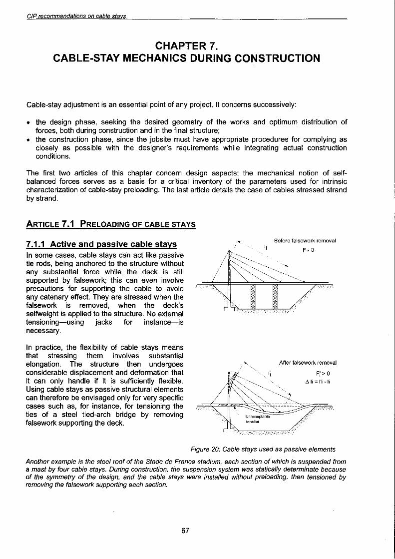

Photo 30: Roof of Stade de France stadium on temporary supports
Conversely, if the deck of a concrete cable-stayed bridge were built on falsework, and if the deckwere encastered into the pylon, when the falsework was removed there would be substantial sagof the main span, resulting in an unacceptable negative moment near the pylon (Figure 20). Thesolution for preventing this situation of course involves pretensioning the cable stays with a jackbefore removing the falsework. This means we are dealing with active structural elements.
This is why, in most cases, cable-stayed structures require pre-tensioning. They are highlystatically indeterminate, and pre-loading the cable stays by pre-tensioning is nothing other thanintroduction into the structure of a set of self-balanced forces. These forces-two equal andopposite forces at the two anchorages-induce no boundary forces overall, but are balanced bythe distribution of forces in the structure (bending moments in the deck and pylon in the case of acable-stayed bridge). This distribution of preloading forces enables the structure to take the effectsof permanent loads with only very little bending.
It is therefore natural to regard a cable stay as a preloaded2 structural element. Adjusting a cablestay then involves applying preloading of a given intensity.
7.1.2 Cable-stay adiustment from the desian point of viewDuring the design of a cable-stayed bridge, finding the right adjustment involves optimizingadjustments of cable-stay tension in order to achieve the following objectives:
.allowable stresses in the cable stays and in the structure, both during construction and aftercommissioning, under variable loads;
.if at all possible, zero or very low bending moment in the structure under permanent loads(selfweight and any prestressing of concrete) in order to limit redistribution due to creep and tofacilitate mid-span jointing.
~
2 Or 'prestressed', but in civil engineering this term is often considered to
using tendons, as within a bridge deck, for instance.
68


£L
"lLl618MJ18S 6UIPJe68J s81::>eJ n::>::>eu I pUB SUO!l!PUO::> 8JmeJ8dw8l JO 8Sne::>8q AIJeln::>llJed 'l::>8Jj8dwl
8q 111M Allle8J pUB 18pOW 8L1l U88Ml8q LI::>leW 8L1l 'SUOllIPUO::> 8llS uo p8::>eld 8Je SlU8W8Jlnb8J
8AIl::>IJlS8J pUB p8lepdn SI 18pOW 8L1l JI U8A3 'UOlleJ8do lU8WlSnfpe 8L1l 6u!Jnp 6UII!eA8Jd SUOIl!PUO::>lem::>e 8L1l JO UOIlelU8S8Jd8J l::>eX8 ue S8AI6 18pOW le::>!J8WnU 8L1l J! SAelS 8lqe::> JO 6u!peOl8Jd
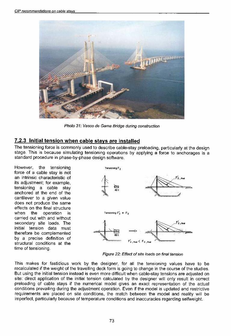
l::>8JJO::> UI llnS8J AIUO 111M J8U61S8p 8L1l Aq p8leln::>le::> UOISU8l leillul 8L1l JO UOlle::>lldde l::>8J!P :8l1SUO p8lSnfpe 8Je SUOISU8l Aels-8Iqe::> U8L1M lln::>IM!p 8JOW U8A8 SI pe8lSui UOISU8lleillui 8L1l 6u!sn lng
"S81pmS 8L1l JO 8SJnO::> 8L1l U! 86ueLl::> Ol 6UIO6 SI WJOJ >j::>8P 6UII18AeJl 8L1l JO lLl618M 8L1l J! p8leln::>le::>8J
8q Ol 8AeLl s8nleA 6UIUOISU8l 8L1l lie JOJ 'J8u6!S8P 8L1l Aq >jJOM snOIPllseJ JOJ S8>jew S!LI.l
UO!SU8J leuy uo speol 8J!S }O J.?8JJ3 :l'l' 8Jn6!::1
"6U!UO!SU8l Jo 8W!l84l le SUO!l!PUO~ leJm~nJlSJO UO!l!U!J8P 8S!~8Jd e I\q
P8lU8W8ldwo~ 8q 8JOJ8J84llsnw elep UO!SU8l le!l!U!841 "speOI 8l!S l\Jepuo~8Slno4l!M pue 4l!M lnO p8!JJe~S! UO!leJ8do 84l u84M8Jm~nJlS leu!J 84l uo Sl~8JJ88wes 84l 8~npoJd lOU S80p8nleJ\ u8J\!6 e Ol J8J\81!lue~
84l Jo PU8 84l le P8Jo4~ueI\els 8lqe~ e 6U!UO!SU8l
'8ldweX8 JoJ ~lU8WlSnfpe Sl!Jo ~!lS!J8l~eJe4~ ~!SU!JlU! uelOU S! I\els 8lqe~ e Jo 8~JOJ
6U!UO!SU8l 84l 'J8J\8MOH
~~ = ~~ 6U!UO!SU81
t
IO~
~
z~ 6U!UO!SU9.L
"aJeMijOS u5!sap ase4d-Aq-ase4d u! aJnpa~oJd pJepue~se S! sa5eJO4~Ue o~ a~JoJ e 5U!Aldde Aq suo!~eJado 5u!uo!sua~ 5u!~elnw!s asne~aq S! S!41 .a5e~s
u5!sap a4~ ~e AIJeln~!lJed '5u!peOlaJd Ae~s-alqe~ aq!J~Sap O~ pasn AIUOWWO~ S! a~JoJ 5u!uo!sua~ a41
palle~SU! aJe SAe~S alqe:> uaLiM UO!Sua~ le!~!UI t"Z"L
uollarulsuoa 6UlJnp e6PlJ8 ewe£) ep oase/\ : J.f: OlOl/d
S/lelS a/qea uo SUO!lepUawwoaaJ d/:J
CIP recommendations on cable stays
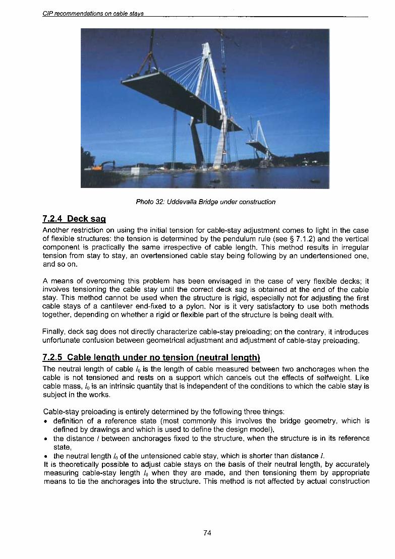
Photo 32: Uddevafla Bridge under construction
7.2.4 Deck saaAnother restriction on using the initial tension for cable-stay adjustment comes to light in the caseof flexible structures: the tension is determined by the pendulum rule (see § 7.1.2) and the verticalcomponent is practically the same irrespective of cable length. This method results in irregulartension from stay to stay, an overtensioned cable stay being following by an undertensioned one,and soon.
A means of overcoming this problem has been envisaged in the case of very flexible decks; itinvolves tensioning the cable stay until the correct deck sag is obtained at the end of the cablestay. This method cannot be used when the structure is rigid, especially not for adjusting the firstcable stays of a cantilever end-fixed to a pylon. Nor is it very satisfactory to use both methodstogether, depending on whether a rigid or flexible part of the structure is being dealt with.
Finally, deck sag does not directly characterize cable-stay preloading; on the contrary, it introducesunfortunate confusion between geometrical adjustment and adjustment of cable-stay preloading.
7.2.5 Cable lenath under no tension (neutrallenath)
Cable-stay preloading is entirely determined by the following three things:.definition of a reference state (most commonly this involves the bridge geometry, which is
defined by drawings and which is used to define the design model),.the distance I between anchorages fixed to the structure, when the structure is in its reference
state,.the neutral length 10 of the untensioned cable stay, which is shorter than distance I.It is theoretically possible to adjust cable stays on the basis of their neutral length, by accuratelymeasuring cable-stay length 10 when they are made, and then tensioning them by appropriatemeans to tie the anchorages into the structure. This method is not affected by actual construction
74
The neutral length of cable 10 is the length of cable measured between two anchorages when thecable is not tensioned and rests on a support which cancels out the effects of selfweight. Likecable mass, 10 is an intrinsic quantity that is independent of the conditions to which the cable stay issubject in the works.

9L
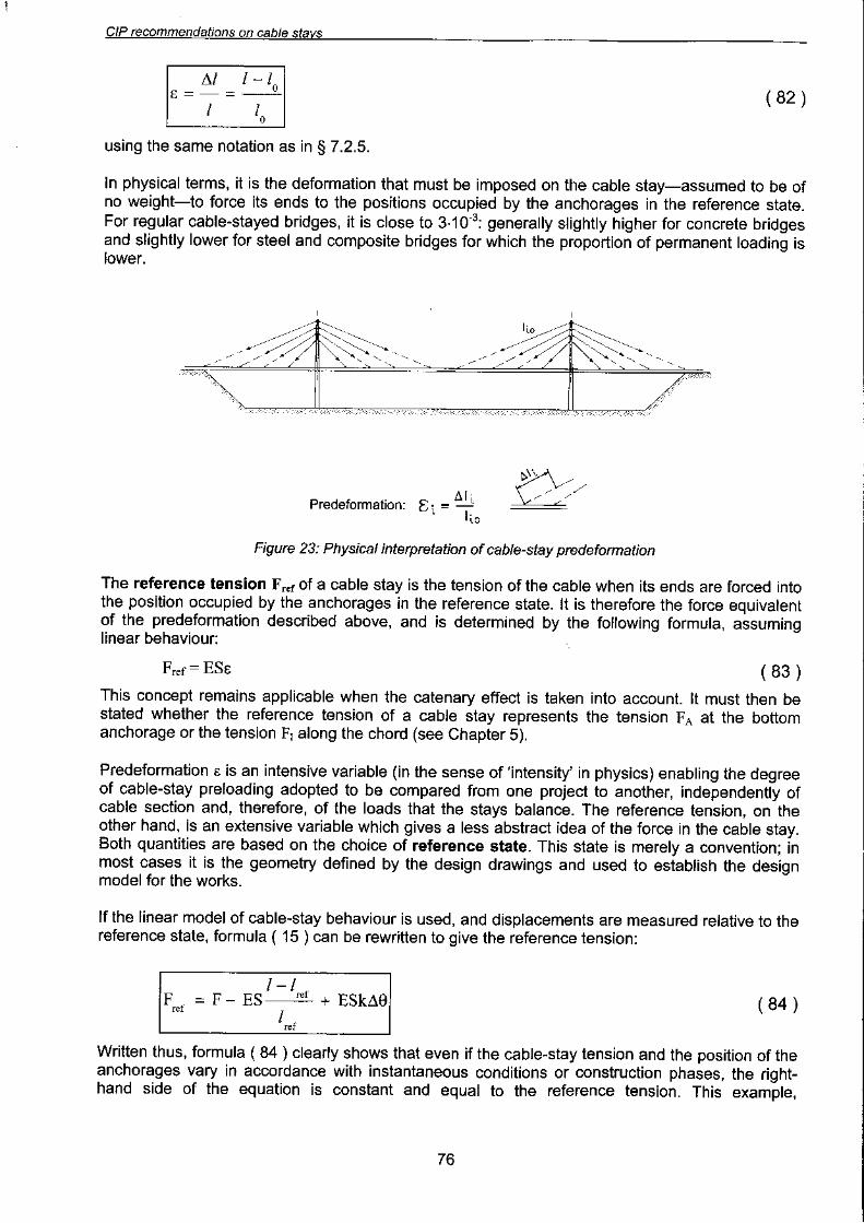
:!.q peU!Jep elqe!JeJ\ leUO!suew!pe e4~ s! 3 UO!~eWJ°.JapaJd
UO!SU8~ 8:)U8J8j8J pue UO!~eWJOj8p8Jd 9'Z'L
"aJe:)
leJnpa~oJd Jo leap leaJ6 e saJ!nbaJ pUB Al!l!qeJnSeaw JO l!W!1 le~!U4~al a4l Ol asol~ S! A~eJn~:)eS!41 'uO!SUal JO SWJal U! A~eJn~~e JO aaJ6ap paJ!sap a4l U!elqo Ol /\Jessa~au S! lUaWaJnseaw4l6ual JoJ '%900'0 JO '9-0~'9 Jo g A~eJn~~e aJ\!lelaJ e le4l pa~npap aq ue~ l! 'sa6p!Jq paAels-alqe:)JoJ £-O~'£ punoJe AileJaua6 S! 3 S'v' '(al~!lJe lxau aas) Aels alqe~ a4l JO uO!leWJOJapaJd a4l S! 3 aJaljM
3
g( ~g)
d
.'IV
:pe4S!lqe~seueeq se4 d!4SUO!~eleJ 6U!MOIIOJ e41 .uo!sue~ Ae~s-elqe~ leU!J e4~ JoJ %l o~ ~ U!4~!M o~ e~eJn~~e.:IV ~e6 o~ AJesse~eu °1/oIV = g 4~6uel Jo ~ueweJnseew Jo A~eJn~~e eA!~eleJ e4~ 6u!u!wJe~ep seAIOAU!
p04~ew 4~6uel-leJ~neU e4~ 'eJn~eJedwe~ elqe~ pUB Se~UeJeIO~ 6U!UO!~!SOd e6eJ04~Ue 6U!JOU61
e6p!Jg puoseJO uo )fJOM J8 eU8JO 6U!J80/.::/ :£'£' OJOLfd
"aueJO Bu!leolJ e Bu!sn 'SJell!d /iJeJodwal uo )foap laals a41 Jo SuO!10aS Bu!Oeldilq
11!nq SeM 40!4M aBp!Je punsaJO a41 Jo silels alqeo a41 JoJ 'a,dwexa JOJ 'pasn SeM p041aw luawlsn(pe S!41
'se~UeJeIO~ese4~ punoJe ~e6 o~ pesn eq o~ eAe4 spo4~ew ~~eJ!pu! pue 'seJ~ew!~ue~ MeJ e U!4~!M O~ AllenSnS! )j~ep e~eJ~UO~ e U! 6u!uo!~!sod e6eJO4~Ue Jo A~eJn~~e e41 °)jJOMeSleJ UO pelqwesse SeJn~~nJ~Slee~s JOJ pe6eS!AUe eq Sew!~eWOS ue~ ~nq 'e~!~~eJd U! e~ueJJn~~o eJeJ f.JeA e eJoJeJe4~ S! S!41°seJ~ew!ll!w MeJ e U!4~!M O~-Ale~eJn~~e f.JeA UMOU)j S! I se6eJO4~Ue ueeM~eq e~Ue~S!p len~~e e4~J! pesn eq AIUO ue~ pue 'Se~UeJeIO~ le~!J~ewoe6 o~ eA!~!SUeS S! ~uew~snrpe peseq-4~6uel 'JeAeMOH
.f\Jol~eJ e4l U! pele~!JqeJeJd SAelS'~le 'eJmeJedwel 'speol f\Jepuo~es eA!ldnJs!p) SUO!l!PUO~ elqe~ JOJ 6u!~seJe~u! ;;'IJeln~!1Jed S! ~I
SJ\elS 81qea uo suoilepu8WWOa8J dl.J
OJQld UO!SU8~ 8~U8J8J8Jpue 3 UO!~eWJOJ8p8Jd :6u!peOI8Jd l\e~s-8Iqe~ JO UO!~eZ!J8~~eJe4~ ~!SU!J~U! 8A!6 SUO!~OU OM~ J84~OU'v'


£O~
~Ale/\!~::>edseJ w/5)j ZL ~' ~ JO w/5)j 980" ~ :pueJ~s eJeq e4~ Jo ssew ::>!eU!lleu!wou .
~Ale/\!~::>edseJ zww 09 ~ JO zww Ov~ :uo!~::>es 5u!~s!seJ leu!wou .
~(spueJ~s L"9 ~.l) ww L"9 ~ JO (spueJ~s Z'9 ~.l) ww Z'9 ~ :Je~ewe!p leU!wou .
:s::>!~s!Je~::>eJe4::> 5U!MOIIOJ e4~ 4~!M pUB '( e~U!eJ~UO::>9Jdel ep elle!J9~S!U!WJe~UI UO!SS!WWO~) dl~ e4~ Aq pe/\oJdde '(OOOZ pes!/\eJ) 9£0-9£ 'v'.::IN pJepue~s4::>ueJ.::I }O s~ueweJ!nbeJ e4~ o~ spueJ~s eJe sAe~s ~Sd Jo (S3.llf\J) s~uewele el!sue~ u!ew e4.l
S~UaWala al!Sua~ U!ew ~ "Z"6
.wn!paw aA!~~a~oJde 4~!M pa~~arU! ad!d !\e~s aA!~~aIIO~ JO 4~ea4s lenp!A!pU! ue pUB 6u!~eo~ le~aw e !\q pa~~a~oJdaJe SpUeJ~S a41 .spUeJ~S lalleJed paJO4~Ue !\llenp!A!pU! WOJJ apew aJe s!\e~s alqe~ pUeJ~S-!~ln~
SAV.lS 318V:> aN~.lS 1311~Vd :A~O~3.lV:> :>Sd Z.u 31:>1.l~V
"1noJ6 al./J se uofSuedxa)o JuafOfjjaoo awes e al\el./ asal./J JO) 'sadfd /.els ,eJaw l./JfM JnOOO Jou
soap uouawoual./d Sfl./J 'Jal\aMOH "1noJ6 Juawao l./JfM paJoa[uf sadfd /.eJs Uf sJapJosfP )0 aOJnos e
aq ueo 3dOH pUB JnoJ6 Juawao al./J)o uofSuedxa)o sJuafofjjaoo al./J uaaMJaq aOUaJajjfp al./J '/.IJSe7
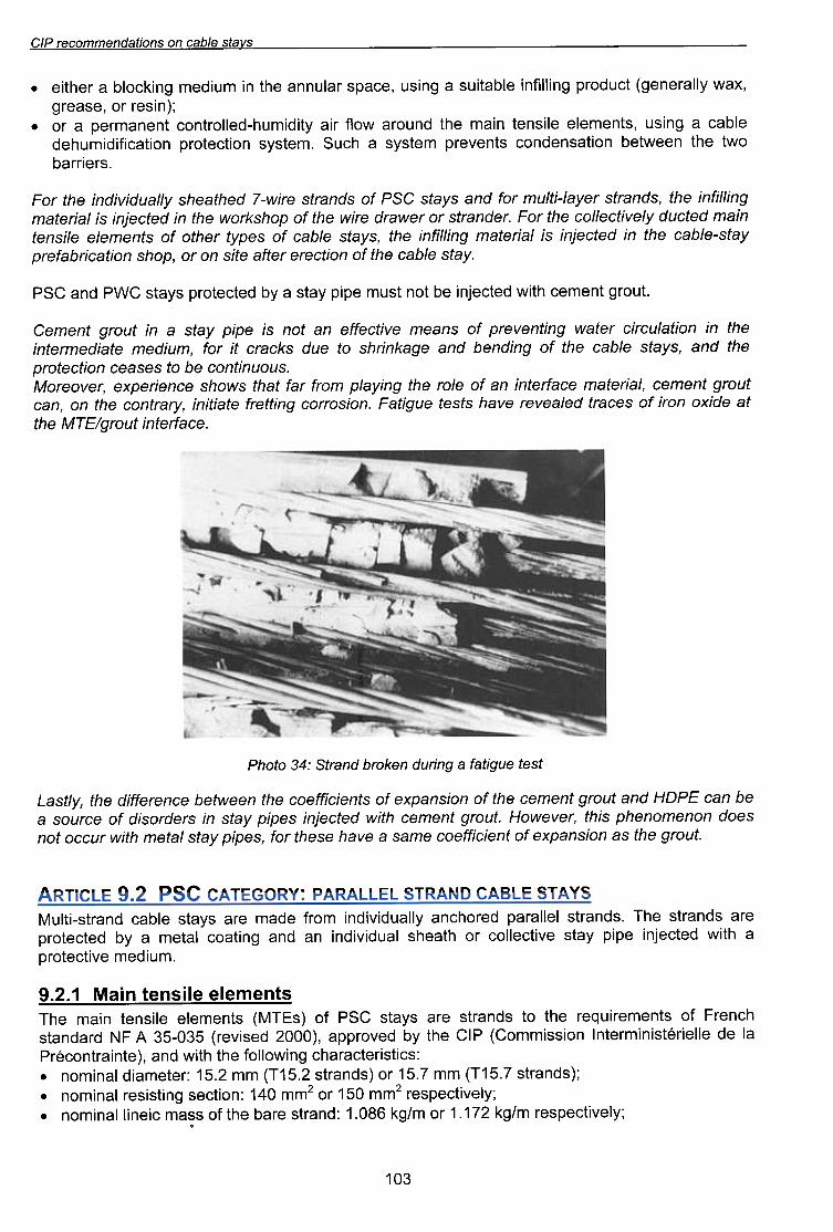
)S8) 8n6!)ej e 6u!Jnp U8>/OJq pUeJ)S :yC O)Ol/d
"8:Jej.l8JUf JnoJ6/31W 8LJJJe apfxo UOJf)O saaeJJ palea/laJ a/leLJ sJsaJ an6/Je.::l "uo/SOJJo:J 6u/JJaJ) aJe/Jfuf 'AJeJJuo:J aLJJ uo 'uea
JnoJ6 JU8W8:J '/efJ8JeW a:Jej.l8Juf ue jO 8/0J 8LJJ 6ufl.e/d WOJj Jej JeLJJ SMOLJS 8:JUafJ8dx8 'J81\08JOW
"SnOnufJuo:J 8q OJ S8Se8:J UOfJ:J8JOJd
8LJJ pue 'sl.eJs 8/qe:J 8LJJ jO 6ufpuaq pue 86e,>/UfJLJS OJ anp s,>/:JeJ:J Jf JOj 'wnfpaw 8JefP8WJaJUf8LJJ uf uofJe/n:JJf:J J8JeM 6UfJU81\8Jd jO sueaw al\fJ:J8Jj8 ue JOU sf adfd l.eJs e Uf JnoJ6 Juawa:J
lnoJ6 ~uewe:) 4~!M pe~:)erU! eq ~OU ~snw ed!d f\e~s e f\q pe~:)e~oJd sf\e~s ~Md pUB ~Sd
'AeJS e/qeo eLlJ}O uo/JoeJe Jeye ells uo JO 'dOllS uo/Jeo/Jqe}eJd
AeJs-e/qeo eLlJ U/ peJoe!u/ S/ /e/JeJew 6u///yu/ eLlJ 'sAeJs e/qeo }O sedAJ JeLlJo }O sJuewe/e e//sueJ
u/ew peJonp A/e/\/Joe//oo eLlJ Jo.::/ 'JepueJJs JO JeMeJp eJ/M eLlJ}o dOLlS>fJOM eLlJ U/ peJoe!u/ S/ /e/JeJew
6u///yu/ eLlJ 'spueJJs JeAe/-mnw JO} pue sAeJs :JSd}O spueJJs eJ/M-L peLlJeeLls N/enp//\/pu/ eLlJ JO.::/
'SJa!JJeqOM~ a4~ uaaM~aq UO!~eSUapuo~ S~uaAaJd Wa~SAS e 4~ns 'Wa~SAS uo!~~a~oJd uo!~e~!l!P!Wn4apalqe~ e 6u!sn 's~uawala al!sua~ u!ew a4~ pUnOJe MOil J!e A~!P!Wn4-paIIOJ~UO~ ~UauewJad e JO .
~(U!SaJ JO 'aseaJ6'xeM AlleJaua6) ~~npoJd 6U!II!lU! alqe~!nS e 6u!sn 'a~eds JelnUUe a4~ U! Wn!paW 6U!)j~Olq e Ja4~!a .
st\els a/qe:) uo SUO!lepuawwo:)aJ d/.'J
CIP recommendations on cable stavs
.protective metal coating of zinc or standard zinc/aluminium alloy applied at coverage of between190 al:ld 350 g/m2 (mean thickness of 26 to 40 11m approximately); .
.strength class fclass 1770 MPa or 1860 MPa;
.strain under maximum load Agt at least 3.5%;
.modulus of elasticity of the bundle of parallel strands of about 195 GPa :t 5%;
.very low relaxation: no more than 2.5% at 1000 hours at 0.7 Fm ( at 20°);
.category B of French standard NF A 35-035 (revised 2000), i.e. MTEs with special capacitiesmeeting the following test conditions:~ fatigue strength: 2 million cycles with maximum stress of 0.45 FOUTS and stress variation of
300 MPa;~ deflected tensile strength coefficient of no more than 20%.
The nominal values and tolerances apply to coated products, i.e. they include for the metalcoating. The strand lengths commonly produced can have welds made on individual wires beforedrawing, but may not be welded during or after drawing.
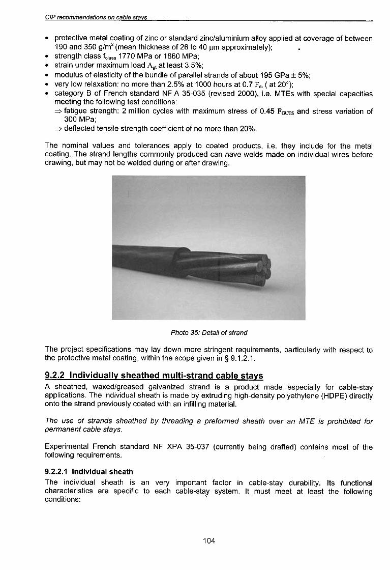
Photo 35: Detail of strand
The project specifications may lay down more stringent requirements, particularly with respect tothe protective metal coating, within the scope given in § 9.1.2.1.
9.2.2 Individually sheathed multi-strand cable stavsA sheathed, waxed/greased galvanized strand is a product made especially for cable-stayapplications. The individual sheath is made by extruding high-density polyethylene (HOPE) directlyonto the strand previously coated with an infilling material.
The use of strands sheathed by threading a preformed sheath over an MTE is prohibited forpermanent cable stays.
Experimental French standard NF XPA 35-037 (currently being drafted) contains most of the
following requirements.
9.2.2.1 Individual sheath
The individual sheath is an very important factor in cable-stay durability. Its functionalcharacteristics are specific to each cable-stay system. It must meet at least the followingconditions: "
104

CIP recommendations on cable stavs
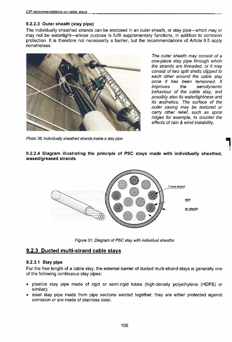
9.2.2.3 Outer sheath (stay pipe)
The individually sheathed strands can be enclosed in an outer sheath, or stay pipe-which mayormay not be watertight-whose purpose is fulfil supplementary functions, in addition to corrosionprotection. It is therefore not necessarily a barrier, but the recommendations of Article 9.5 applynonetheless.
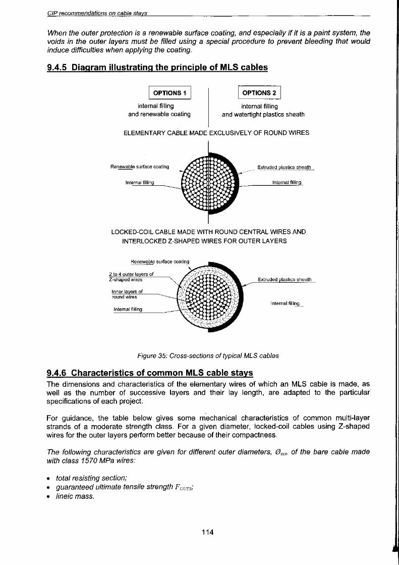
The outer sheath may consist of aone-piece stay pipe through whichthe strands are threaded, or it mayconsist of two split shells clipped toeach other around the cable stayonce it has been tensioned. Itimproves the aerodynamicbehaviour of the cable stay, andpossibly also its watertightness andits CBsthetics. The surface of theouter casing may be textured orcarry other relief; such as spiralridges for example, to counter theeffects of rain & wind instability.
Photo 36: Individually sheathed strands inside a stay pipe 1
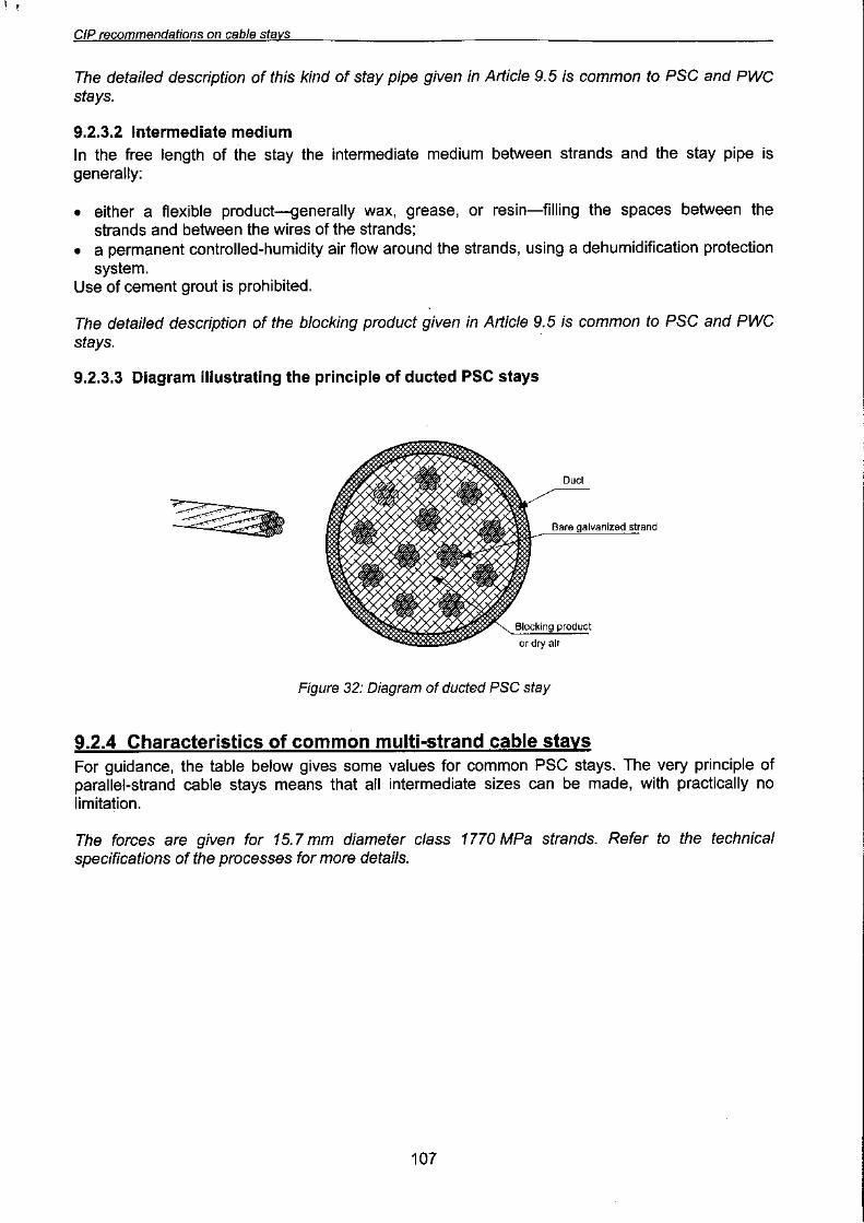
9.2.2.4 Diagram illustrating the principle of PSC stays made with individually sheathed,waxed/greased strands
Individual sheath
-Optional outer sheath
'""-A!L
Figure 31.. Diagram of PSG stay with individual sheaths
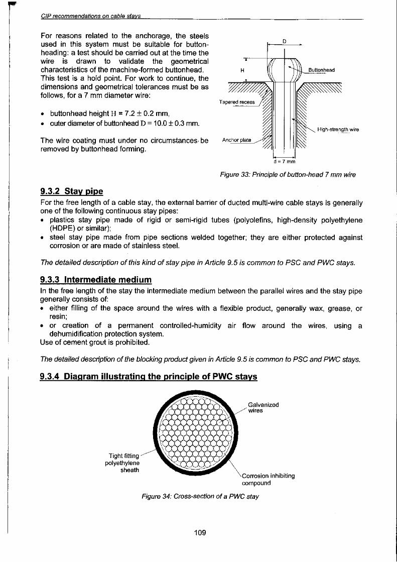
9.2.3 Ducted multi-strand cable stays
9.2.3.1 Stay pipeFor the free length of a cable stay, the external barrier of ducted multi-strand stays is generally oneof the following continuous stay pipes:
.plastics stay pipe made of rigid or semi-rigid tubes (high-density polyethylene (HOPE) or
similar);.steel stay pipe made from pipe sections welded together; they are either protected against
corrosion or are made of stainless steel.
106


CIP recommendations on cable stavs
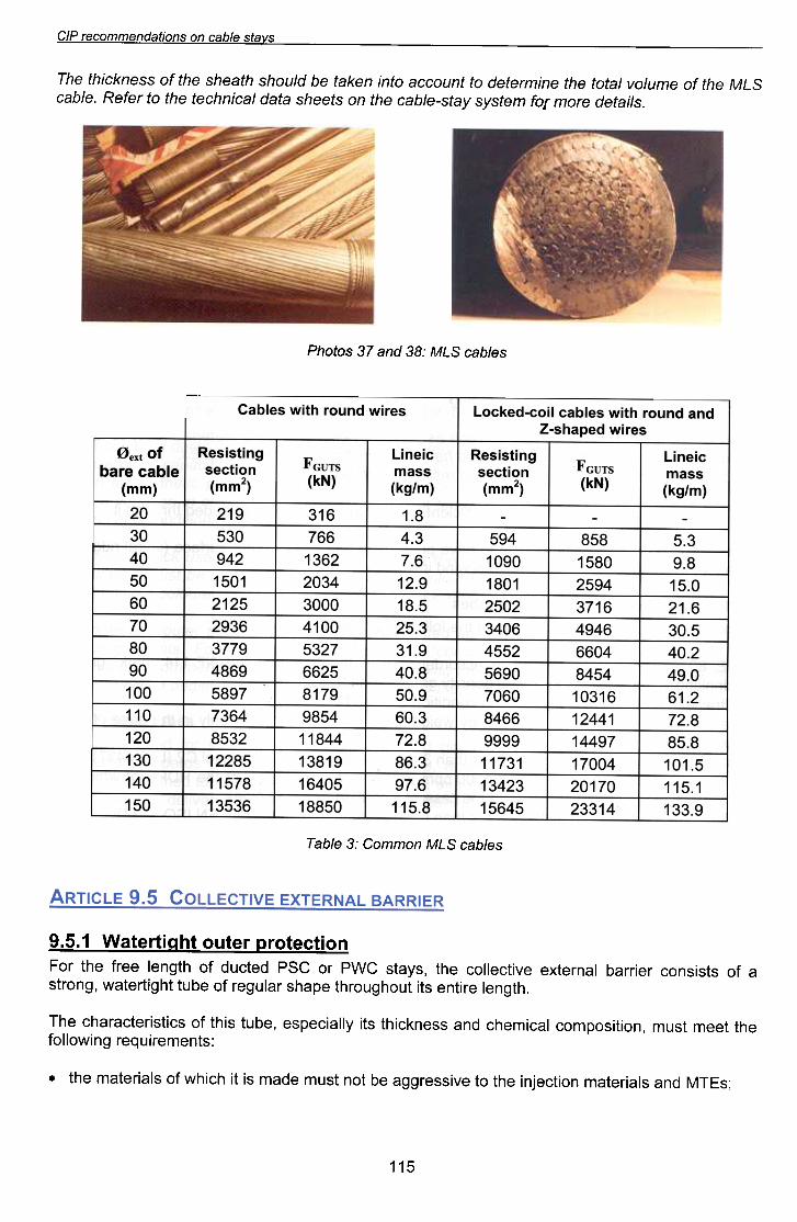
The thickness of the sheath should be taken into account to determine the total volume of the MLScable. Refer to the technical data sheets on the cable-stay system for more details.
Photos 37 and 38: MLS cables
Cables with round wires Locked-coil cables with round andZ-shaped wires
Oext of
bare cable(mm)
Resistingsection
(mm1
Resistingsection
(mm1
Lineicmass
(kg/m)
F GUTS
(kN)F GUTS
(kN)
20
30
40
50
60
70
80
90
100
110
120
130
140
150
219
530
942
1501
2125
2936
3779
4869
5897
7364
8532
12285
11578
13536
316
766
1362
2034
3000
4100
5327
6625
8179
9854
11844
13819
16405
18850
Lineicmass
(kg/m)
1.8
4.3
7.612.9
18.5
25.3
31.9
40.8
50.9
60.3
72.8
86.3
97.6
115.8
594
1090
1801
2502
3406
4552
5690
7060
8466
9999
11731
13423
15645
858
1580
2594
3716
4946
6604
8454
10316
12441
14497
17004
20170
23314
5.3
9.815.0
21.6
30.5
40.2
49.0
61.2
72.8
85.8
101.5
115.1
133.9
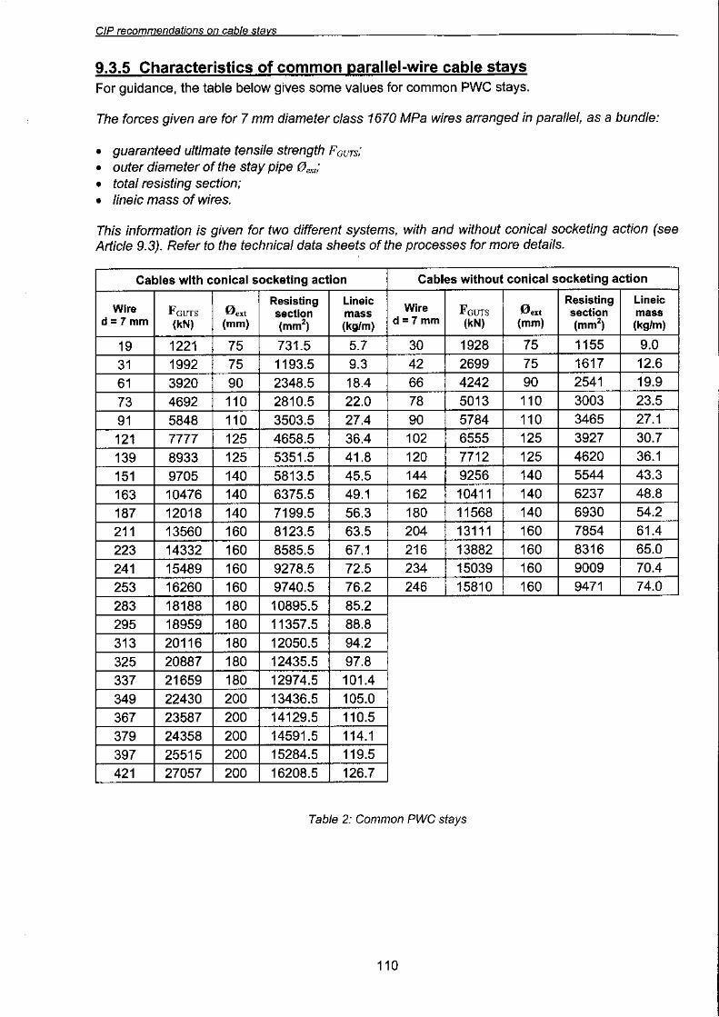
Table 3: Common MLS cables
9.5.1 Watertiaht outer orotectionFor the free length of ducted PSG or PWG stays, the collective external barrier consists of astrong, watertight tube of regular shape throughout its entire length.
The characteristics of this tube, especially its thickness and chemical composition, must meet the
following requirements:
.the materials of which it is made must not be aggressive to the injection materials and MTEs;
115


CIP recommendations on cable stavs
If tube sections are to be welded together, the tube must be no less than 3 mm thick. Welds mustcomply with the terms of appropriate standards (e.g. NF P22-471, quality 1). The fatigue strengthof welded joints must be substantiated.
Steel stay pipes must have an external corrosion-protection system guaranteeing at least 6 yearsbefore rust index Ri 1 defined by the applicable standard is reached.
At the time of publication of these Recommendations, the applicable standard is French standardNF T30-071, "Degradation des surfaces peintes". This level of guarantee of corrosion protectioncan be achieved by cleaning the surface to level OS 2.5 and painting the bare steel. Regularmaintenance is required thereafter (every ten to fifteen years approximately). Alternatively, paintedgalvanized or stainless-steel tubes can be used.
9.5.2 Blockina comDoundThe filling material injected into the intermediate areas must not be a cause of wear (frettingcorrosion or fretting fatigue) of the MTEs it is supposed to protect. It is for this reason that cementgrout is prohibited.A flexible protective material is generally used to fill the inside of the duct. Alternatively, a dry airflow can be kept up around the MTEs by means of a dehumidification system.
Flexible protective products are generally pumpable petroleum products:
.a microcrystalline wax, i.e. a malleable crystallized solid consisting of saturated hydrocarbonswhich are injected in a liquid state (temperature between 80 and 120°C) [6]; or
.a mineral-oil-based grease, i.e. a plastic lubricant obtained by dispersion of an insolublethickener (such as complex metallic soap) in a lubricating fluid (mineral oil) to form a stabilizedthree-dimensional network; or
.a resin or flexible polymer injected at an appropriate temperature.
The filling material must not be aggressive to the MTEs or the material of which the stay pipe ismade. The absence of aggressivity is determined by physical testing or by reference to previous
projects.The filling material must retain its protective properties without interruption, and continue to protectthe steel despite the extreme thermal loading to which it might be subject throughout the lifetime ofthe project.
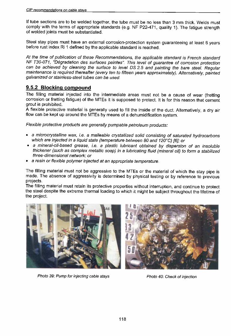
Photo 39: Pump for injecting cable stays Photo 40: Check of injection
118

OG~
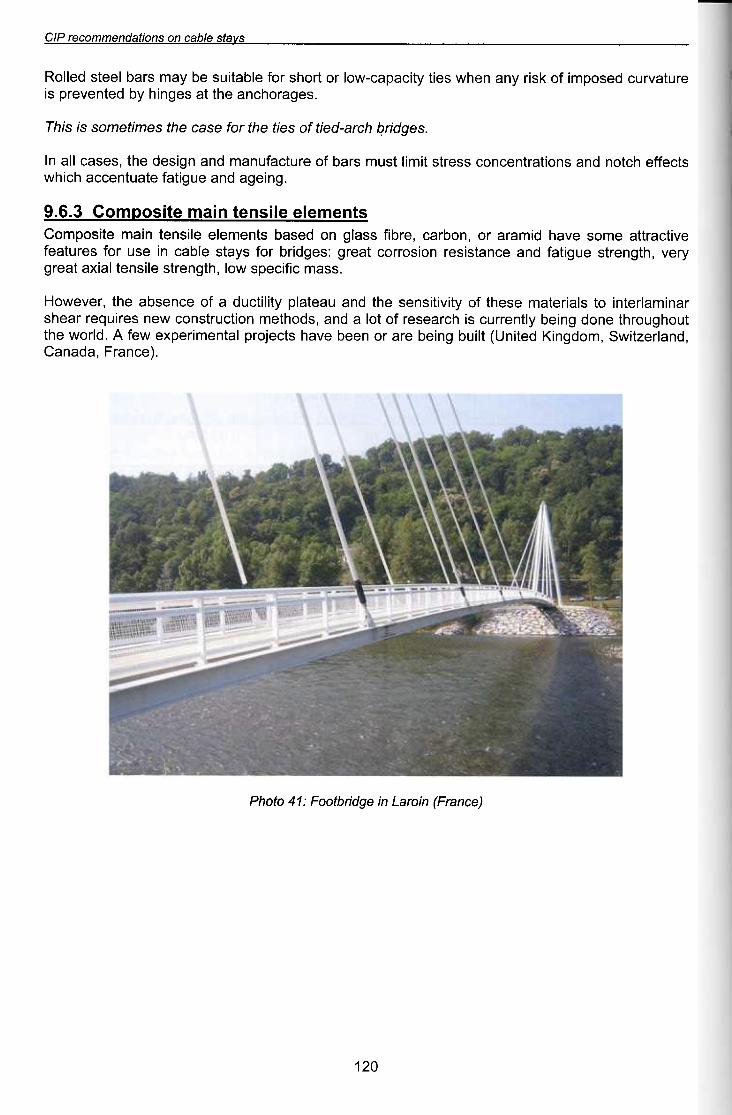
(aaueJ::/) u/OJe7 U/ a6p/JQ100::/ : ~ 17 01oLld
"( e~ueJ::I 'epeue~'pUeIJeZ~!MS 'wop6u!>I pe~!Un) ~I!nq 6u!eq eJe JO ueeq eJ\e4 s~~efoJd le~Uew!Jedxe Mej 'v' 'PIJOM e4~~n046noJ4~ euop 6u!eq AI~UeJJn~ s! 4~JeeseJ jO ~ol e pUB 'Sp04~eW UO!~~nJ~SUO~ MeU seJ!nbeJ Jee4SJeU!WeIJe~U! O~ Sle!Je~eW ese4~ jO A~!J\!~!SUeS e4~ pUB nee~eld A~!I!~~np e jO e~uesqe e4~ 'JeJ\eMOH
.ssew ~!j!~8dS MOI'4l6U8JlS 81!SU8lle!Xe le8J6f.J81\ '4l6u8JlS 8n6!lej pUB 8~UelS!S8J UO!SOJJO~ le8J6 :s86p!Jq JOj sf\els 8lqe~ U! 8Sn JOj S8Jnle8jel\!l~eJ»e 8WOS 81\e4 p!WeJe JO 'uoqJe~ '8Jq!j SSel6 uo p8seq SlU8W818 81!SU8l U!eW 8l!SOdWO~
s~uawala al!SUa~ U!eW a~!soawo:> £"9"6
"6u!e6e pUB en6!leJ elemUe~~e LI~!LlMSl~eMe LI~lOU pUB SUO!leJlUe~UO~ SSeJlS l!W!llSnW SJeq JO eJm~eJnuew pUB u6!sep eLll 'sese~ lie UI
.se6P!Jq LlaJe-pe!J}o sell eLlJ JO} esea eLlJ sew!Jewos S! S!Lll
.se5eJ04~ue e4~ ~e se5u!4 f\q pe~ueAeJd s!eJn~eAJn~ pesodw! 10 )jS!J f\ue ue4M se!~ f\~!~ede~-Mol JO ~04s J01 elqe~!ns eq f\ew sJeq lee~s pello~
SABlS 91qB.? UO SUO!lBPU9WWO.?9J dl.'J

CIP recommendations on cable stavs
10.1.4 Corrosion protection and watertiahtnessThe design of anchorages must extend the two barriers defined in Chapter.9 without a break, toprotect against corrosion and keep water out of the free length of the cable stay.
10.1.5 RemovabilityAnchorage design must allow for renewal of cables.
ARTICLE 10.2 GENERAL PROVISIONS COMMON TO ALL ANCHORAGE TYPES
10.2.1 Filterina out anaular deviationsAs stated in Chapter 6, angular deviation of cable stays engenders stresses which can be of the
same order of magnitude as those due to the axial loads and can have harmful effects in terms of
fatigue.
Appropriate systems should therefore be provided to limit or eliminate the effect of cable-staydeviations at the anchorage head, i.e. to "filter out" changes in angle between the cable and
anchorage.
There are two main techniques for this, the effects of which are quite similar:.stiffening the anchorage zone: this involves increasing the flexural stiffness of the cable stay.
One means of achieving this is to attach a steel tube around the cable, near the anchorage, andmechanically fix the end of the tube to the anchorage head or to the structure.
.guiding the cable: this involves partially or totally preventing transverse cable-stay movement,i.e. the movement of each of its component parts, using a guide system placed a certaindistance from the anchorage. The effectiveness of such a guide system depends on its distancefrom the anchorage, as seen in § 6.2.4.1
The angular-deviation filtering system can also playa role in damping (absorption of vibrationalenergy by viscosity or friction).
The design of a cable stay's guide system must take account of transverse and flexural forcesresulting from cable deformations.
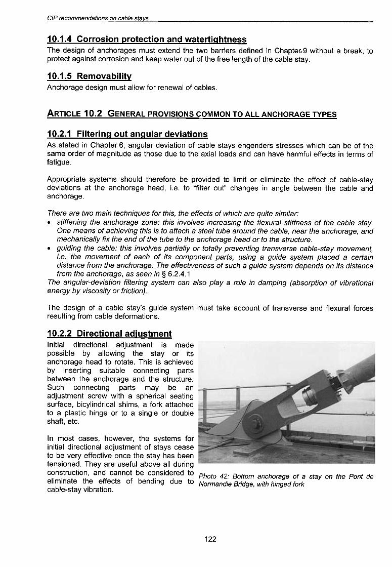
10.2.2 Directional adiustmentInitial directional adjustment is made
possible by allowing the stay or its
anchorage head to rotate. This is achieved
by inserting suitable connecting parts
between the anchorage and the structure.
Such connecting parts may be an
adjustment screw with a spherical seating
surface, bicylindrical shims, a fork attached
to a plastic hinge or to a single or double
shaft, etc.
In most cases, however, the systems forinitial directional adjustment of stays ceaseto be very effective once the stay has beentensioned. They are useful above all during I
construction, and cannot be considered to Photo 42: Bottom anchorage of a stay on the Pont deeliminate the effects of bending due to Normandie Bridge, with hinged forkcable-stay vibration.
122
£G~
"8UOZ 85eJO4~ue 8J!IU8 841 45noJ41 f..lsnOnU!IUO~
PU8lX8 lsnw 6 J81de4:J U! P8U!J8P SJ8!JJeq UO!I~810Jd-uo!sOJJO~ f..Jelu8w8Idwo~ OM} 841
JeeM pue UO!SOJJO:> ~SU!etje UO!~:>e~OJd "£"Z"O ~
.elqe~ e4~ 6u!6ewep ~nO4~!M (seeJ6ep £v. ~ +) sue!peJ!II!W 9Z + Jo UO!~e!Aep ~de~~e o~peu6!sep eq ~snw ~ 'Z.O ~ U! o~ peJJeJeJ swe~sl\s ep!n6 e4~ JO se6eJO4~Ue 'eS!MJe4~O pe~e~s sselun
(~.V.G~88S)s~ed 6U!l~8UUO~ 84l JO S8~UeJ810l UO!lellelSU! 84l JO SS8~X8 U! SUO!le!J\8p Jeln6ue ~!lelS 6u!ld8~~e
Jo 8lqede~ 8q lSnW s86eJO4~Ue 841 .8Jm~nJlS p8peolun 84l Jo SUO!l!PUO~ 8~!J\J8S 84l J8pUn(AJeu8le~) lU8Wu6!le f,els-8Iqe~ le8p! 84l Jo luno~~e 8)jellsnw s~ed 6u!l~8UUO~ Jo UO!lelu8!JO 841
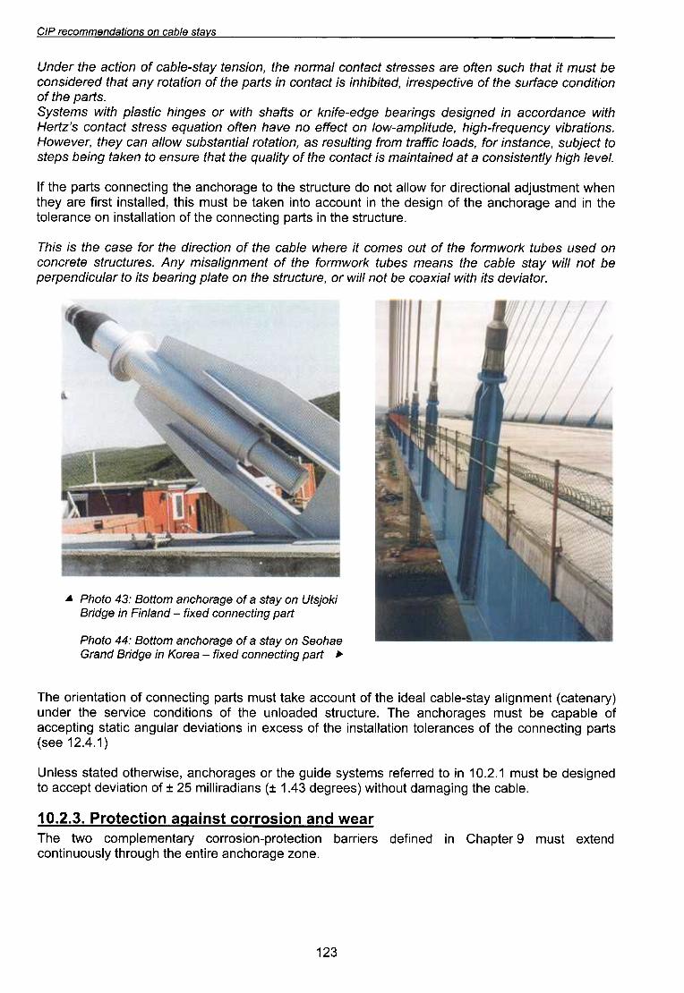
...J.ied 6ulJoauuoo paXI) -eaJO)/ UI a6pIJB pueJf)aeqoas uo I.els e )0 a6eJoqoue WO110B :yy °loqd
}Jed 6u!Jaauuoa pax!) -pue,u!:i U! a6P!Ja!>/o!sJn uo /ieJs e )0 a6eJo/.{aue wonoa :Ctl' oJo/'{d P'
"JOJefl\ep sJf LlJfM /efxeoo eq JOU I/!M JO 'eJnjonJJs eLlJ uo eJe/d 6UfJeeq sJf OJ Je/nofpuedJed
eq JOU I/!M /ieJs e/qeo eLlJ sueew seqnj >/JOMWJO] eLlJ ]0 Juewu6f/esfw /iU'rI "seJnjonJJs eJeJOUOO
uo pesn seqnj >/JOMWJO] eLlJ ]0 Jno sewoo Jf eJeLlM e/qeo eLlJ]o uofJoeJfp eLlJ JO] eseo eLlJ sf SfLli
'eJm~nJ~S e4~ U! stJed 5u!~~euuo~ e4~ Jo uO!~elle~SU! uo e~ueJelo~e4~ U! pue e5eJO4~Ue e4~ Jo u5!sep e4~ U! ~uno~~e O~U! ue)je~ eq ~snw S!4~ 'pelle~SU! ~SJ!J eJe f\e4~
Ue4M ~uew~snrpe leUO!~~eJ!p JOJ Molle ~ou op eJn~~nJ~s e4~ O~ e5eJO4~Ue e4~ 5u!~~euuo~ stJed e4~ JI
"Iel\el 46f4l.flueJsfSUO{) e Je peufeJufew sf J{)eJuo{) e4J jO I.Jflenb e4J Je4J eJnsue oJ ue'>feJ 6ufeq sdeJs
oJ J{)e[qns 'e{)UeJsuf JOj 'speol {)fjJeJJ WOJj 6umnseJ se 'uofJeJOJ lefJueJsqns Molle ue{) l.e4J 'Jel\eMOH
"SUOfJeJqfl\ l.{)uenbeJj-46f4 'epnJfldwe-MOI uo J{)ejJe ou el\e4 ueyo UOfJenbe SseJJs J{)eJUO{) s,zJ.JeH
4JfM e{)uepJo{){)e Uf peu6fsep s6UfJeeq e6pe-ejfU'>f JO sye4s 4JfM JO se6Uf4 {)fJse,d 4JfM sweJsl.s
"sJ.Jed e4J jOUOfJfPUO{) e{)ejJns e4J jO el\fJ{)edseJJf 'peJfqf4uf Sf J{)eJuo{) uf sJ.Jed e4J jO uofJeJOJ I.ue Je4J peJepfSUO{)
eq Jsnw Jf Je4J 4{)nS ueyo eJe sesseJJs J{)eJuo{) ,eWJoU e4J 'uofsueJ l.eJs-elqe{) jO uofJ{)e e4J JepUn
SAelS 8/qe.? UO suo/lepu8wwo.?8J d/:J
CIP recommendations on cable stavs
Abbreviation Gripping Category of cable concerned
Conical wedges (split-cone) gripped in theanchorage head *c PSC (sheathed or ducted)
Swaged sleeves bearing on theanchorage head *5 PSC (sheathed or ducted)
Buttonheads bearing against a plate+ possible conical socketing action byfilling with Resin, etc.--
Bor B+R PWC
Fanning out + conical socketing action byI
filling the socket casing with Resin, etc.F+R MLS
* May be complemented with a suitable rigid filling material to improve fatigue strength
Further distinctions can be made between the different kinds of anchorage:
.live (or stressing) anchorage, where the cable is tensioned, and dead-end (or fixed)anchorage where no tensioning is performed;
.bottom anchorage, on the deck, and top anchorage in the pylon. The bottom anchorage of acable stay is particularly exposed to water running down the stay, and therefore requires special
preventative measures,..static anchorage, the head of which is static with respect to the structure, and adjustable
anchorage, the head of which can be moved axially.
There is an important difference between cable stays using type C anchorages and all the others:the unloaded length of a cable made up of parallel strands anchored by split-cone wedges can bechanged during adjustment phases, unlike the other kinds of cable stays for which the unloadedlength of the tensioned wire, strand, or cable is irreversibly fixed before jacking takes place.
ARTICLE 10.4 TYPE C ANCHORAGES FOR PARALLEL-STRAND CABLE STAYS
Type C anchorages are used for sheathed or ducted multi-strand cable stays.
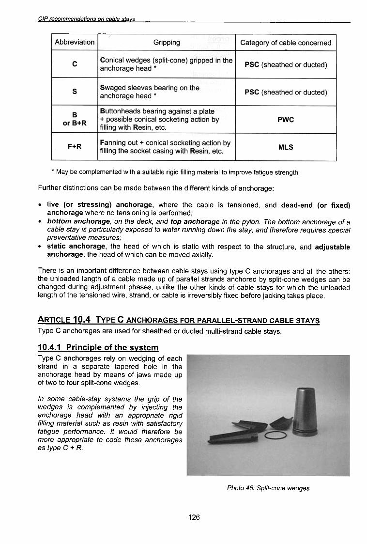
10.4.1 Principle of the systemType C anchorages rely on wedging of eachstrand in a separate tapered hole in theanchorage head by means of jaws made upof two to four split-cone wedges.
In some cable-stay systems the grip of thewedges is complemented by injecting theanchorage head with an appropriate rigidfilling material such as resin with satisfactoryfatigue performance. It would therefore bemore appropriate to code these anchoragesas type C + R.
Photo 45: Split-cone wedges
126
CIP recommendations on cable stavs
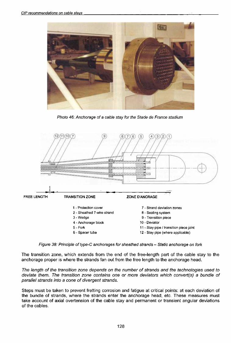
Photo
46: Anchorage of a cable stay for the Stade de France stadium
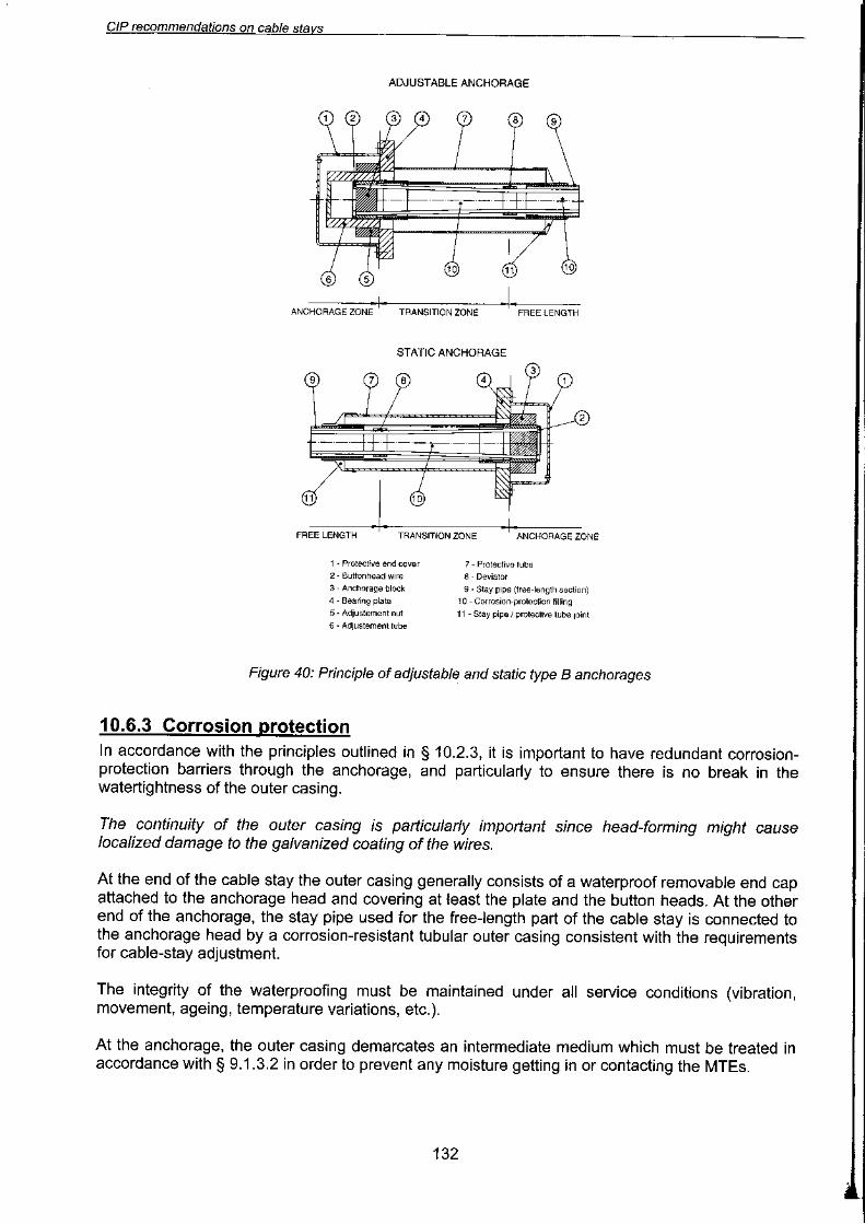
~14 ",:";'"FREE LENGTH TRANSITION ZONE ZONE D'ANCRAGE
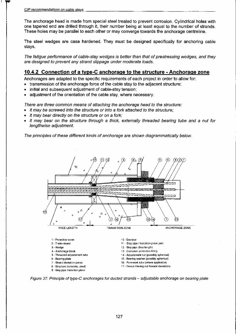
7 -Strand deviation zones
8 -Sealing system
9 -Transition piece
10 -Deviator
11 -Stay pipe I transition piece joint
12 -Stay pipe (where applicable)
1 -Protection cover
2 -Sheathed 7 -wire strand
3 -Wedge
4 -Anchorage block
5 -Fork
6 -Spacer tube
Figure
38: Principle of type-C anchorages for sheathed strands -Static anchorage on fork
The transition zone, which extends from the end of the free-length part of the cable stay to theanchorage proper is where the strands fan out from the free length to the anchorage head.
The length of the transition zone depends on the number of strands and the technologies used todeviate them. The transition zone contains one or more deviators which convert(s) a bundle ofparallel strands into a cone of divergent strands.
Steps must be taken to prevent fretting corrosion and fatigue at critical points: at each deviation ofthe bundle of strands, where the strands enter the anchorage head, etc. These measures musttake account of axial overtension of the cable stay and permanent or transient angular deviationsof the cables.
128


CIP recommendations on cable stavs
ofas
The commonly used meansconnecting socket casings arefollows (see Figures 41 and 42):
INTERNALLY THREADED SOCKET CASING WITH THREADED EXTENSION
:g>
~~~
.socket casing with threaded borebehind the socket: this threadingtakes a threaded transfer rodanchored to the structure by meansof an adjustment and locking nut,.
.socket casing with external threadingtaking an adjustment and locking nut;
.socket casing with fork and pintransferring the cable-stay force to aknuckle plate welded to the structure;
.socket casing with lugs takingseveral high-strength threaded rodswith adjustment and locking nut.
Adjustement~
1 -Socket
2 -Internally threaded socket casing
3- MLS cable stay
4 -Externally threaded transfer rod
EXTERNALLY THREADED SOCKET CASING WITH ADJUSTEMENT NUT
Adjustement~
1- Socket 3 -MLS cable stay
2 -Externally threaded socket casing 4 -Adjustement and locking nut
Figure 41.. Different kinds of adjustable type F+R socketcasings for MLS cable stays
FORK-TYPE SOCKET CASING
@)
4 -Knuckle pin
5 -Knuckle plate1 -Socket
2 -Fork-type socket casing
3 -MLS cable stay
SOCKET CASING WITH FIXING LUGS
..Photo 47: Top anchorage of a cable stay on
Seyssel Bridge
Figure 42: Different kinds of adjustable typeF+R socket casings for MLS cable stays (contd)
3 -MLS cable stay
4 -High-strength threaded rods
1 -Socket
2 -Lug-type socket casing
134


CIP recommendations on cable stavs
Each specimen tested should reflect actual conditions of use, and have all the actual anchoragesystems used with the cable stays, corrosion-protection accessories, and any products injectedinto the cable stays. Appropriate measures should be taken to reproduce the actual conditions inwhich the anchorages work in the actual structures. If the cable-stay system uses different live anddead-end anchorages (dead-end anchorage with swaged sleeves and live anchorage with jaws,
for instance), both anchorages should be tested simultaneously.
PWC and PSC cable-stay systems generally use a deviator a certain distance from the anchoragewhich allows the MTEs to fan out from the free length to the anchorage (see Chapter 10). MLScable stays too are sometimes configured this way. On test specimens the deviator should beplaced no further from the anchorage than the distance specified for the cable-stay system.
In actual structures the deviator may be connected to the structure, either rigidly or with somefreedom of movement, as when it is connected to the structure by an elastic tube or viscousdamper. Since it is not reasonable to attempt to reproduce exactly the particular conditions of eachstructure for the qualification test, the most unfavourable transverse guide system should be used,i.e. that with a totally free deviator without any damping.
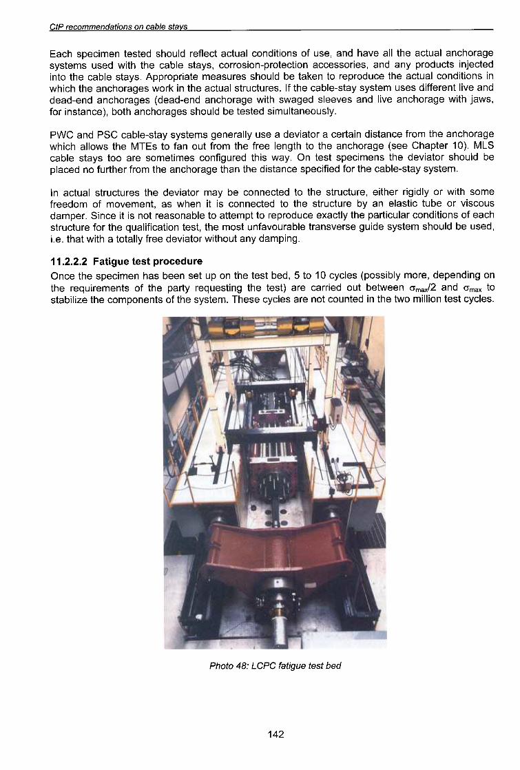
11.2.2.2 Fatigue test procedure
Once the specimen has been set up on the test bed, 5 to 10 cycles (possibly more, depending on
the requirements of the party requesting the test) are carried out between O'max/2 and O'max tostabilize the components of the system. These cycles are not counted in the two million test cycles.
Photo 48: LCPC fatigue test bed
142


CIP recommendations on cable stavs
anchor block on sideplate with transverse jack
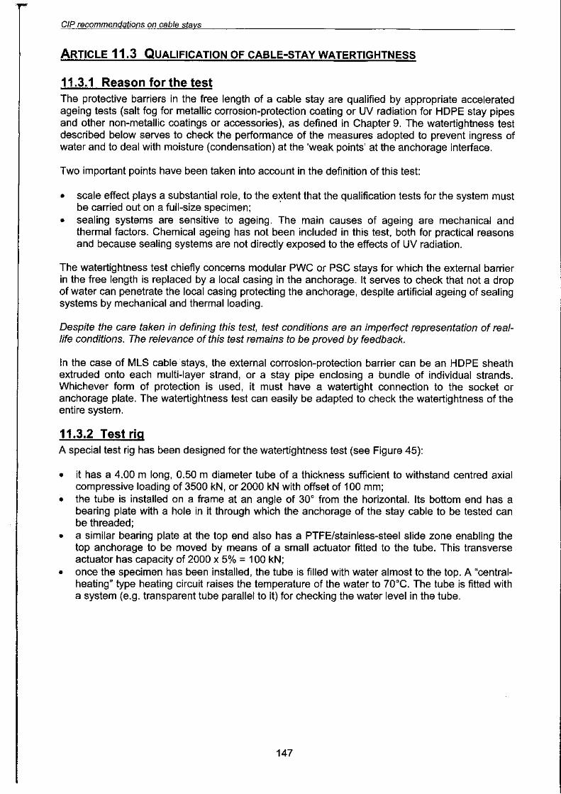
Figure 45: Watertightness test rig
11.3.3 Watertiahtness test procedure
11.3.3.1 Preparation of specimenThe specimen tested is a cable-stay bottom anchorage under near-real conditions: unit withcapacity of 7000 kN (i.e. 27 x 15 mm dia. strands in the case of a PSG stay) fitted with all itsaccessories. The top end is a live anchorage for tensioning the cable stay and connecting its stay
pipe (where applicable).
The top anchorage is placed on the tube centreline and the cable is threaded into the test rig andtensioned to 0.10 FOUTS. Moisture indicators of blotting paper are placed on each MTE and at anysensitive point in the local casing where water should not penetrate.
All deviation and sealing systems are installed (caps, stay pipe and couplers, ring seals, etc.
In the case of PWG or PSG stays, the deviator is placed at the minimum distance from theanchorage specified for the system, and is left free to move laterally.
The stay pipes of ducted PWG and PSG stays have watertight seals with both anchorages,creating a single watertight compartment over the full length of the cable. The test shouldreproduce the same seal conditions at both ends of the stay pipe of the specimen in order to checkthat temperature variation has no effect on the seals. However, it is not necessary to install thestay pipe of individually sheathed PSG stays if it is not intended to be a watertight barrier.
11.3.3.2 Mechanical and thermal ageing
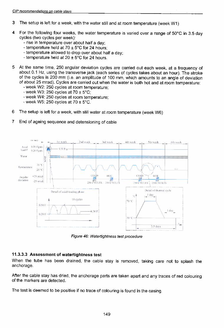
The following ageing sequence is applied for a period of about 6 weeks (see Figure 46):
10 loading and unloading cycles between 0.2 and 0.5 FGUTS, using a multistrand or annular jackon the top anchorage, at room temperature (20°C :t 5), for several hours.
1
The cable is stressed to 0.30 FOUTS and held at this stress for the rest of the test. After sealingany points of possible leakage between the anchorage and the bearing plate, the tube is filledwith water to 100 mm below the top bearing plate (representing water pressure on the bottomanchorage of about 0.2 bar). Mains water (no salt) coloured red with a suitable dye is used.
2.
148
6v~
'6u!se:)
e4~ u! punoJ S! 6u!JnOI°:) JO e:)eJ~ ou J! el\!~!sod eq o~ peweep S! ~se~ e41
'pe~~e~ep eJe SJe>jJew e4~ Jo6u!JnOI0~ peJ Jo se~eJ~ AUe pUB ~ede ue>je~ eJe s~ed e6eJ04~Ue e4~ 'pe!Jp se4 Ae~S elqe~ e4~ Jeij'rj
.e6BJOLj~UBeLjl LjSBldS Ol lOU eJB~ 6U!)jBl 'peAOWeJ S! ABlS elqB~ eLjl 'peU!BJp ueeq sell eqm eLjl ueLjM
JS9J SS9UJ46!JJ9JeM Jo JU9WSS9SSV t"t"t" ~ ~
8Jnp8':JOJd JS8J SS8UJ4b'!J18JeM :gv 8Jnb'!::/
elqe~ JO 6u!uo!sue~ep pUB e~uenbes 6u!e6e JO PU3L
(9M )j88M) 8JmeJ8dw8~ WOOJ ~e J8~eM II!~S 4~!M ')j88M e JOj Y81 S! dn~8S 84.l9
'~o9 =+= OL ~e sal:Jl'\:J 09G :9M )jaaM -~aJn~eJadwa~ WOOJ ~e sal:Jl'\:J 09G :PM )jaaM -
~~o9 =+= OL ~e sal:Jl'\:J 09G :£M )jaaM-~aJn~eJadwa~ WOOJ ~e sal:Jl'\:J 09G :GM )jaaM-
:aJn~eJadwa~ WOOJ ~e pUB ~04 4~oq s! Ja~eM a4~ Ua4M ~no pa!JJe:J aJe Sal:Jl'\~ "(peJW 9G ~noqe JOUO!~e!Aap JO al5ue ue O~ s~unowe 4:J!4M 'ww 00 ~ JO apn~!ldwe ue "a"!) ww DOG S! sal:Jl'\:J a4~ Joa)joJ~s a41 "(Jn04 ue ~noqe sa)je~ sal:Jl'\:J Jo sa!Jas 4:Jea) )j:Jer aSJaASUeJ~ a4~ 5u!sn 'ZH ~. 0 ~noqeJo l'\:JuanbaJJ e ~e ')faaM 4:Jea ~no pa!JJe:J aJe sal:Jl'\:J UO!~e!Aap Jeln5ue 09G 'aw!~ awes a4~ ~\;j9
"SJnO4 VG JoJ ~og =+= OG ~e Ple4 eJn~eJedwe~ -~I\ep e Jle4 ~noqe JeAO doJp o~ peMOlle eJn~eJedwe~ -
~SJnO4 VG JoJ ~og =+= OL ~e Ple4 eJn~eJedwe~ -~I\ep e Jle4 ~noqe JeAO eJn~eJedwe~ u! es!J -
:()jeeM Jed sel~l\~ OM~) sel~l\~I\ep g"£ u! ~oOg JO e5ueJ e JeAO pe!JeA S! eJn~eJedwe~ Je~eM e4~ 'S)jeeM JnoJ 5U!MOIIOJ e4~ J°::lv
,( ~M )f88M) 8JmeJ8dw8J WOOJ Je pue II!JS J8JeM 84J 4J!M ')f88M e JOj ij81 S! dm8S 841£
sJ\e/s 8/qe.? UO suOI/epU8WWO.?8J d/:J


£9~
"(pU!M WnJp Jad UJn} auo 'pauJn} pue pUnOM) WnJp UO paJO~S Ae~S alqe~ "g
~pa~~afu! punodwo~ alq!xalJ leUO!~!ppe pue AI!JeJodwa~ pa4~e~~e saqn~ ~!do~Sala~ "L
~(Alle~!~aA pauo!~!sod) s6u!se~ ~a)j~os O~U! paJnod u!saJ "9
~pawJoJ spea4uo~~nq pue palle~SU! a6eJ04~Ue puo~as "S
~ad!d Ae~s 3dOH O~U! papeaJ4~ pue paddeJM-leJ!ds alpunq "v
:saJ!M Jo alpunq uo pa!ldde punodwo~ 6u!II!JU! "£
:pawJoJ spea4uo~~nq pue palle~su! a6eJ04~Ue ~SJ!J "l'
:4~uaq ~!~ewo~ne ue uo 4~6ual o~ ~n~ SaJ!M laa~s "~
:sa6e~s 6U!MOIIOJ a4~ U! d04S)jJOM a4~ U! pa~e~!JqeJaJd aJe sAe~s ~Md
:uo!~d!J~sao
sAe~s ~Md Jo uo!~eJedaJd Z" ~ "£"Z ~
.spee4 e6eJO4~Ue OM~ e4~ U! selo4 6u!4~~ew U! peJo4~ue eJe l\e4~ ~e4~ pUB 4~6uelJ!e4~ ~nO46noJ4~ lelleJed eJe SpUeJ~S e4~ ~e4~ eJnSUe O~ ue)je~ eq Plno4s SeJnSeeW e~e!JdoJddV'
"e6edd!IS pueJ~s f\ue S~ueAeJd ~e4~ we~sf\s 6u!6peM-eJd e~e!JdoJddeue f\q 'f\e~s elqe~ e4~ Jo 6u!sseJ~s o~ Jo!Jd 'e~eld u! Ple4 eq ~snw Se6peM e4~ ese~ 4~!4Mu! 'Se6peM eUO~-~!lds 4~!M sf\e~s elqe~ pUeJ~S-!~lnW 6u!)jew JOJ pesn eq ue~ eJnpe~oJd ewes e41.
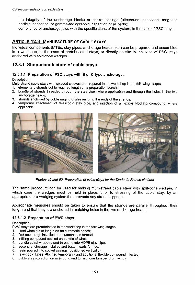
wn/pe1S 8aUeJ::J 8p 8pe1S 841 JO) s/ie1s 8/qea )0 uo/1eJed8Jd :09 pue 6v SOl04d
'alqe:)!lddeaJa4M 'punodwo:) 6u!)j:)°IQ alQ!xalJ e Jo uo!1:)a[u! pue 'ad!d lie~s :)!do:)sala~ Jo ~uaw4:)e~~e liJeJodwa~ "v
:spueJ~s a4~ Jo spua a4~ o~uo saAaals JO 6u!6eMS-Plo:) IiQ paJ04:)ue spueJ~s "£
:spea4 a6eJ04:)ueOMI a4~ U! sal04 a4~ 46noJ4~ pue (aIQe:)!ldde aJa4M) ad!d lie~s a4~ 46noJ4~ papeaJ4~ spueJ~s Jo alpunq "Z
~4:)uaq uo!~eJedaJd e uo 4~6ual paJ!nbaJ o~ ~n:) spueJ~s liJe~uawala ' ~
:sa6e~s 6U!MOIIOJ a4~ U! d04S)jJOM a4~ U! paJedaJd aJe saAaalS pa6eMS 4~!M slie~s alqe:) pueJ~S-!~lnlAJ
:uo!~d!J:)saa
sa6eJO4:>ue ad1.t ~ JO S 4t!M s1.ets ~Sd lo uoneJedaJd ~. ~ "£"Z ~
SAe~s alqe:> 10 aJn~:>elnuew-doLiS ~ "£"Z ~
.se6peM eUO~-~!lds lj~!M peJolj~uesf.e~s ~Sd Jo ese~ elj~ U! e~!s uo f.1~~eJ!p JO 'sf.e~s pe~e~!JqeJeJd Jo ese~ elj~ U! 'dOljS>jJOM e U!pelqwesse pUB peJedeJd eq ue~ (.~~e 'Speelj e6eJolj~ue 'sed!d f.e~s 'S31ll\J) s~ueuodwo~ lenp!/\!pul
SA "V.lS 318"V~ ~O 3~n.l~"V~nN"V1I\I £"Z ~ 31~1.l~"V
.sl\e~s ~Sd Jo 8Se:) 84~ U! 'W8~SI\S 84~ JO SUO!~e:)!J!:)8ds 84~ 4~!M sMef 86eJ04:)ue Jo 8:)ue!ldwo:)
~(s~ed lie JO UO!~:)8dsu! :)!4deJ60!peJ-ewwe6 JO 'UO!~:)8dsu! 81:)!~ed
:)!~8u6ew 'UO!~:)8dsu! punOSeJ~ln) s6u!se:) ~8)j:)OS JO s)j:)°lq 86eJ04:)ue 84~ JO 1\~!J68~U! 84~
sl\els e/qea uo SUO!lepuewwoaeJ d/:J
CIP recommendations on cable stavs
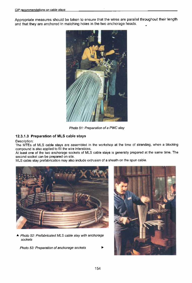
Appropriate measures should be taken to ensure that the wires are parallel throughout their lengthand that they are anchored in matching holes in the two anchorage heads. .
Photo 51: Preparation of a PWC stay
12.3.1.3 Preparation of MLS cable stays
Description:The MTEs of MLS cable stays are assembled in the workshop at the time of stranding, when a blockingcompound is also applied to fill the wire interstices. .At least one of the two anchorage sockets of MLS cable stays is generally prepared at the same time. Thesecond socket can be prepared on site.MLS cable stay prefabrication may also include extrusion of a sheath on the spun cable.
...Photo 52: Prefabricated MLS cable stay with anchoragesockets
Photo 53: Preparation of anchorage sockets
..
154
99~
"ed!d Ae~S pe4s!u!J e4~ Jo ~uewel\oweS!M4~6uel Jo uo!~eln~le~ u! seJn~eJedwe~ wnw!u!w pue wnw!xew Jo uo!~eJep!suo~-
'4~6uel o~ ~n~ S! ed!d Ae~S e4~ Ue4M eJn~eJedwe~ Jo uo!~eJep!suo~ -
:suo!~e!Jel\ eJn~eJedwe~ 4~!M A~!I!q!~edwo~ .
~Ae~S elqe~ pe~eldwo~ e4~ uo uo!~~e~oJd UO!SOJJO~ Jo A~!nU!~UO~ .
~(peUO!SUe~S! Ae~S elqe~ e4~ ue4M ~uewel\ow eS!M4~6uel) ~uew~snrpe JoJ pue '6u!uo!sue~ JoJ '(ed!dAe~S e4~ Jo ep!su! e4~ o~ sse~~e) s31ll\J Jo u!-6u!peeJ4~ JoJ s~ueweJ!nbeJ e4~ 4~!M A~!I!q!~edwo~ .
:s~ueweJ!nbeJ 6U!MOIIOJ e4~ ~eew ~snw ~I .~!O~U! pepeeJ4~ eJe s31.l/\J e4~ eJoJeq Alq!SJel\eJJ! peU!WJe~ep S! pelle~SU! eq O~ ed!d Ae~S JO 4~6uel e41.
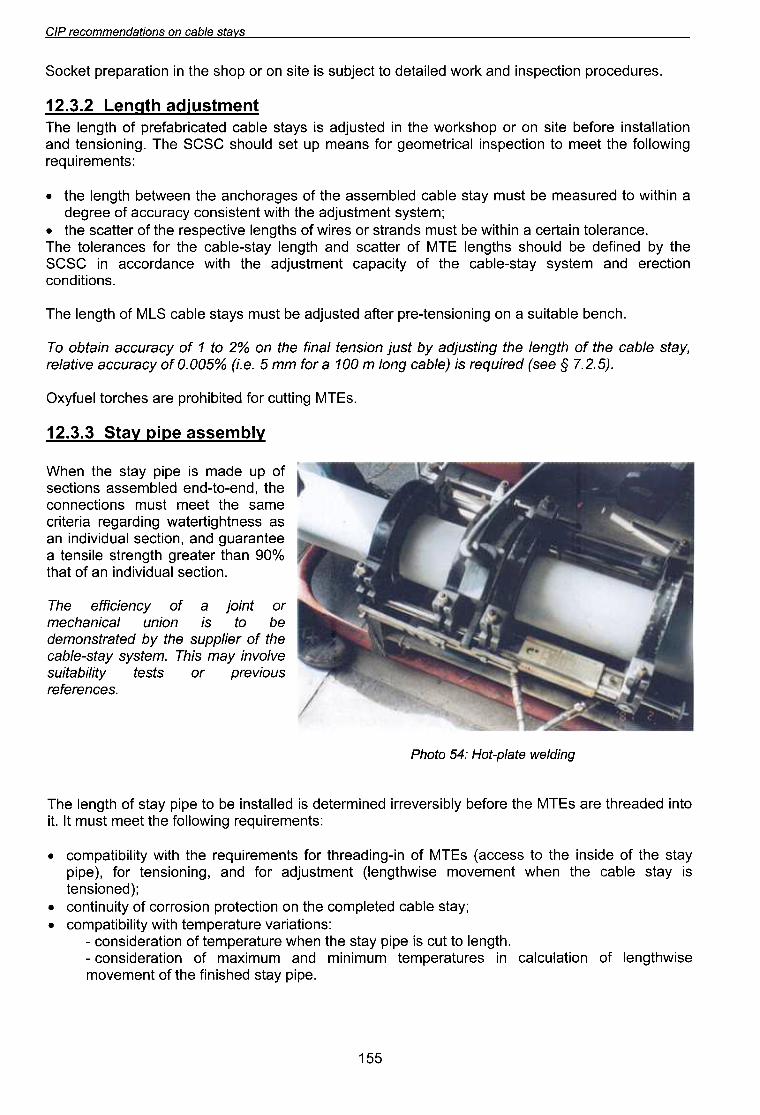
6UfP{8M 818{d-l0H :yg 01°4'd
'SB:JUBJB)BJSno!/lBJd JO slsB1 /im!qe1!nSB/I/O/lU! /iew S!LI.L 'wB1s/is /ie1s-B/qe:J
BLl1 )0 JB!/ddns BLl1 /iq pB1eJ1SUOWBPBq 01 S! uo!un /e:J!UeLl:JBwJO 1u!of e )0 /i:JUB!:J!JJB BLI.L
.uo!~~es lenp!l\!pu! ue JO ~e4~%06 ue4~ Je~eeJ6 4~6ueJ~s el!SUe~ eee~ueJen6 pUB 'UO!~~eS lenp!l\!pU! uese SSeU~46!~e~eM 6u!pJe6eJ e!Je~!J~ewes e4~ ~eew ~snw SUo!~~eUUO~
e4~ 'pue-o~-pue pelqwesse suo!~~esJo dn epew S! ed!d f\e~s e4~ ue4M
AIQwasse ad!d Ae~s £'£'Z~
.S31lAJ 6u!~~n~ JOj pe~!q!40Jd eJB se4~Jo~ lenjAXQ
"(9"G"L § BaS) peJlnbeJ Sl (e/qe'J Buo/ W OOt. e JOj ww 9 "e"u %900"0 jO A'JeJn'J'Je el\lle/eJ'Aels e/qe'J el/l jO l/lBue/ el/l BuIlsn[pe Aq lsn[ uoIsuel/eUlj el/l uo %G 01 t. jO A'JeJn'J'Je ulelqo 01
"4::>ueq elqe~!ns e uo 5u!uo!sue~-eJd Jeye pe~snfpe eq ~snw sJ\e~s elqe::> SlV'J JO 4~5uel e41
'SUO!~!PUO~uo!~~eJe pUB we~sl\s I\e~s-elqe~ e4~ JO I\~!~ede~ ~uew~snrpe e4~ 4~!M e~UepJO~~e U! ~S~Se4~ I\q peU!Jep eq Plno4s S4~6uel 3.lLI'J JO Je~~e~S pUB 4~6uel I\e~s-elqe~ e4~ JOJ Se~UeJeIO~ e4.l
.e~UeJeIO~ U!e~e~ e U!4~!M eq ~snw SpUeJ~S JO SeJ!M JO S4~6uel eA!~~edseJ e4~ JO Je~~e~S e4~ .
~we~sl\s ~uew~snrpe e4~ 4~!M ~Ue~S!SUO~ l\~eJn~~e JO eeJ6epe U!4~!M O~ peJnSeeW eq ~snw I\e~s elqe~ pelqwesse e4~ JO se6eJO4~Ue e4~ ueeM~eq 4~6uel e4~ .
:SlueWeJlnbeJ6UIMOIIOj e4lleew Ol uoIl~edsul le~IJleWoe6 JOj sueew dn les Pln04s ~S~S e4.l "6UIUOlsuel pUBuollellelSul eJojeq ells uo JO d04S)jJOM e4l U! pelsnfpe S! sl\els elqe~ pele~IJqejeJd jO 4l6uel e4.l
JuawJsnipe 4Jljual Z"£"Z ~
'S8Jnp8~OJd UO!~~8dSU! pue )jJOM p81!e~8p O~ ~~8fqns S! 8~!S UO JO dO4S 84~ U! uo!~eJed8Jd ~8)j~OS
Sl\elS elqe~ uo SUO!lepUeWWo~ej dlO
CIP recommendations on cable stavs
These requirements generally call for use of telescopic systems or sleeves.
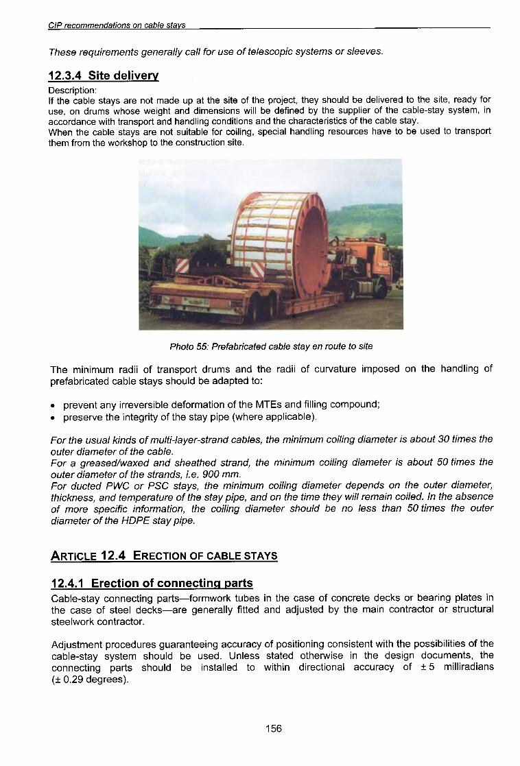
12.3.4 Site deliveryDescription:If the cable stays are not made up at the site of the project, they should be delivered to the site, ready foruse, on drums whose weight and dimensions will be defined by the supplier of the cable-stay system, inaccordance with transport and handling conditions and the characteristics of the cable stay.When the cable stays are not suitable for coiling, special handling resources have to be used to transportthem from the workshop to the construction site.
Photo 55: Prefabricated cable stay en route to site
The minimum radii of transport drums and the radii of curvature imposed on the handling ofprefabricated cable stays should be adapted to:
.prevent any irreversible deformation of the MTEs and filling compound;.preserve the integrity of the stay pipe (where applicable).
For the usual kinds of multi-layer-strand cables, the minimum coiling diameter is about 30 times theouter diameter of the cable.For a greased/waxed and sheathed strand, the minimum coiling diameter is about 50 times theouter diameter of the strands, i.e. 900 mm.For ducted PWG or PSG stays, the minimum coiling diameter depends on the outer diameter,thickness, and temperature of the stay pipe, and on the time they will remain coiled. In the absenceof more specific information, the coiling diameter should be no less than 50 times the outerdiameter of the HOPE stay pipe.
ARTICLE 12.4 ERECTION OF CABLE STAYS
12.4.1 Erection of connectina partsCable-stay connecting parts-formwork tubes in the case of concrete decks or bearing plates inthe case of steel decks-are generally fitted and adjusted by the main contractor or structuralsteelwork contractor.
Adjustment procedures guaranteeing accuracy of positioning consistent with the possibilities of thecable-stay system should be used. Unless stated otherwise in the design documents, theconnecting parts should be installed to within directional accuracy of :t 5 milliradians(:t 0.29 degrees).
156
L9~
:Je410Ue Jeye euo 'pUeJ1S 4:)ee JO! ."415uel e1e!JdoJdde!o sJe5ue4 5u!sn 'elqe:) iiJe!I!Xne ue Aq pepuedsns eq JO pueJ1S lSJ!! e41 uo
lSeJ ue:) 11 "se5eJO4:)ue OMI e41 ueeM1eq pelle1SU! S! ed!d Ae1s pelqwesse AISnO!AeJd e41 'elqe:)!ldde eJe4M .
:sde1s 5U!MOIIO! e41!O SlS!SUO:)AileJeue5 uoneJedo S!41. "aWn e 1e pUeJ1S euo pe1:)eJe ueyo eJe se5peM euo:)-l!lds 41!M peJO4:)ue sAe1s :)Sd
:uond!J:)sea
UOn:>aJa pUeJ~S-Aq-pUeJ~S £"P"Z ~
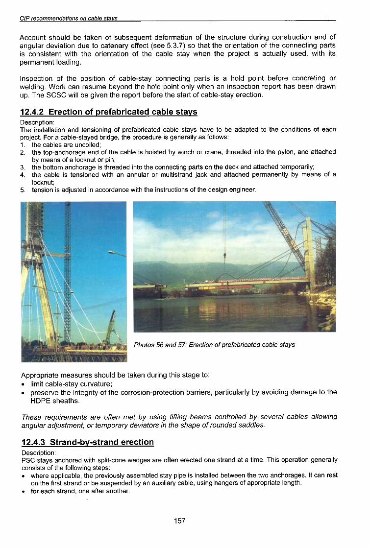
.se/ppes pepunOJ)O edeLJs eLJJ uf sJoJef/lep /iJeJodweJ JO 'JuewJsn[pe Je/nBue
BUfMO//e se/qe:J /eJe/les tfq pe//oJJuo:J sweeq BUfYf/ Bufsn tfq Jew ueyo eJe sJueWeJfnbeJ eseLJl
.s4~ee4S 3dOHe4~ o~ e6ewep 6U!p!OAe f.q f.IJeln::>!~ed 'sJe!JJeq uo!~::>e~oJd-uo!soJJo::> e4~ Jo f.~!J6e~u! e4~ eAJeseJd .
~eJn~eAJn::> f.e~s-elqe::> ~!W!I .
:O~ e6e~s S!4~ 6u!Jnp ue)je~ eq Pln04s seJnseew e~e!JdoJdd'v'
SAelS 8/qe::J p81e::JIJQe)8Jd )0 UOll::J8J3 :L9 pue 99 SOI0l/d
"JaaU!DUa UD!Sap a4I Jo Suoll~nJISU! a4I 41!M a~uepJo~~e U! palsnfpe S! uO!Sual "s~Inu)j~ol
e Jo sueaw liq IillUaUewJad pa4~ene pue )j~ef pUeJISlllnW JO Jelnuue ue 41!M pauO!SUal S! alqe~ a4I "v
~1i1!JeJodwal pa4~ene pue )j~ap a4I uo slJed Dull~auuo~ a4~ DIU! papeaJ4I S! aDeJ04~Ue wonoq a4I "£~U!d JO Inu)j~ol e Jo sueaw liq
pa4~ene pue 'UOllid a4I DIU! papeaJ4I 'aueJ~ JO 4~U!M liq pa1S!04 S! alqe~ a4I JO pua aDeJ04~Ue-dol a4I "G~pal!O~Un aJe salqe~ a4I "~
:SMOIIOJ se IilleJaUaD S! aJnpa~oJd a4I 'aDP!Jq paliels-alqe~ e JO::l l~afoJd
4~ea Jo SUOIl!PUO~ a4I OI paldepe aq OI aAe4 slielS alqe~ paIe~!JqeJaJd Jo DU!UO!SUal pue uollelle~su! a41:uOlld!J~saa
SAeJS alqe:> paJe:>!JqejaJa jO UO!J:>aJ3 Z.V.Z ~
.uo!~:)eJe I\e~s-elqe:) jO ~e~s e4~ eJojeq ~odeJ e4~ ueJ\!6 eq II!M :JS:JS e4.l 'dnUMeJp ueeq se4 ~odeJ uo!~:)edsu! ue Ue4M I\luo ~u!od Pl04 e4~ puol\eq ewnseJ ue:) )jJOM '6u!PleM
JO 6u!~eJ:)uo:) eJojeq ~u!od Pl04 e s! s~ed 6u!~:)euuo:) I\e~s-elqe:) jO uo!~!sod e4~ jO uo!~:)edsul
"6U!pBOllUeUBWJedSl! 4l!M 'pesn I\IIBm~B S! l~eroJd e4l Ue4M I\BlS elqB~ e4l Jo UOijBlUe!JO e4l 4l!M lUelS!SUO~ S!SlJBd 6uij~euuo~ e4l Jo uOijBlUe!JO e4llB4l os (L "£'s ees) l~eJJe I\JBuelB~ Ol enp UOijB!J\ep JBln6uB
JO pUB uOij~nJlSUO~ 6u!Jnp eJm~nJlS e4l JO UOijBWJOJep luenbesqns JO ue>jBl eq Pln04s lUnO~~V'
S/lB1S 81qBO UO suoflBPU8WWOO8; d/~

CIP recommendations on cable stavs
1. the strand is erected by being threaded up the stay pipe or hoisted with a telpher system. At the end ofthis phase the free length of the strand is approximately in its final position but its ends are notnecessarily threaded through the anchorages. .
2. the ends of the strand are threaded through the appropriate holes in the two anchorage blocks and thesplit-cone wedges are fitted.
3. the strand is tensioned with a monostrand jack.stay tension is adjusted in accordance with the instructions of the design engineer.
Photo 58: Cable-stay strands being threaded into the stay pipe one by one (Vasco de Gama Bridge)
Close attention should be paid to special features of the cable stay (anchorages, guidancesystems, and possibly saddles) while it is being threaded into place to avoid damaging theindividual protection of strands.
Appropriate measures should be taken to prevent the leading end of the strand damaging the staypipe or the sheaths of the strands installed previously.
Appropriate measures should be taken to ensure that the strands are parallel throughout theirlength and that they pass through matching holes in the two anchor blocks.
12.4.4 Corrosion orotection durina erectionDepending on the cable-stay system, not all the corrosion-protection systems for MTEs may havebeen put in place at the time the cable is installed on the structure. If the time to application of thedefinitive corrosion-protection system exceeds a few months, the SCSC should have an
appropriate temporary corrosion-protection system applied.
ARTICLE 12.5 TENSIONING AND ADJUSTMENT
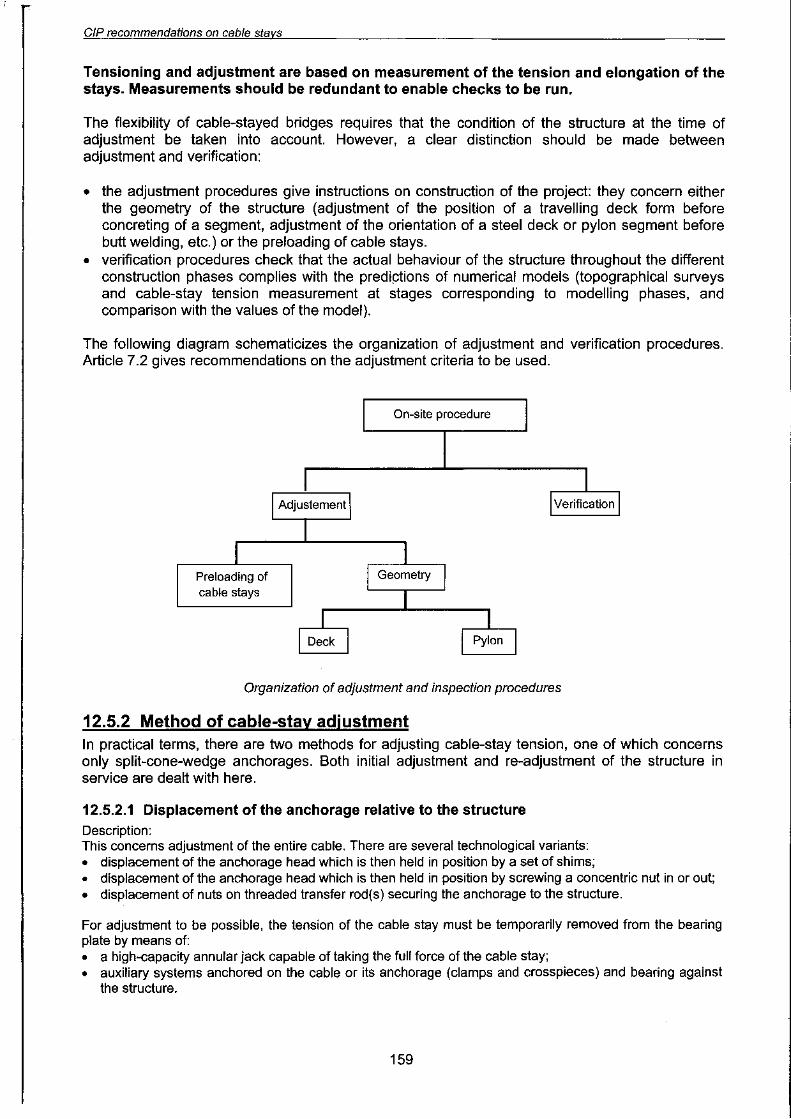
12.5.1 Oraanization of adiustment and verificationAt the end of the erection operations, the cable stay may have been attached to its twoanchorages temporarily (in the case of certain prefabricated cable-stay systems) or permanently,and tensioned to a given stress.
Tensioning and adjustment introduce the level of preloading specified by the designers into thecable stay. Depending on the sequencing of construction of the project, these operations may becarried out in one go or in a series of successive thresholds, in close collaboration with the designengineer.
Re-adjustments may also be necessary during the lifetime of the project (seeChapter 13).
158

CIP recommendations on cable stavs
Photo 59: Annular jack Photo 60: Erection of MLS cable stays on Seyssel
Bridge -tensioning system
The design of the anchorage head must allow an amplitude of adjustment taking account of someor all of the following quantities, depending on the cable-stay technology used:.uncertainty on the unloaded position of the anchorages;.uncertainty on the loading of the structure at the moment of tensioning phases, and on the
stiffness of the structure;.uncertainty on the unloaded length, tension, and temperature of the cable stay;.extension of the cable stay to attain the required preloading;.factors outlined in § 14.2.6;.safety factor.
The amplitude of adjustment is defined once and for all after manufacture of the anchorage parts(length of peripheral threading on the anchorage head, length of threaded transfer rods, maximumheight of shims that can be placed between the anchorage head and its bearing plate on thestructure, etc.). It must therefore be correctly predicted.
It is possible to make allowance for de tensioning of the cable stay by leaving a length of threadingbehind the concentric nut or behind the nuts on the threaded transfer rods, or by introducing shimsbetween the anchorage head and its bearing plate right from the start. This requirement must alsobe correctly predicted.
The design of the area where the anchorage is attached to the structure must take account of:.sufficient clearance around and behind the anchorage, for installation of jacks and other
systems necessary for tensioning or adjustment;.means of access and handling systems suitable for heavy equipment.
These geometrical conditions should be specified in the technical data sheet of the cable-staysystem given by the SCSC.
This point must be examined with extra special care when adjustment on the structure in service isnot done in the same way as the initial tensioning and adjustment.
If clamps are used to attach the adjustment systems directly to the cable, they must be designedso as not to damage the corrosion protection of the cable stay.
It must be ascertained that the adjustment systems (concentric nuts, transfer rods, etc.) will remainin operating condition throughout the lifetime of the structure: threads protected against anydamage, knife-edge bearings protected against corrosion, etc.
160

~9~
ss8aoJd UO!SU8JOS/ 8L1J 6u!sn 'pueJJs >laB!pueJJsouow e LIJ!M ~JS 8/qea e 6U!UO!SU8.L ..~9 oJoLld
"eJeJs /eu!6!JoeJe!JdoJdde ue OJ e/l!Je/eJ spueJJs sno!Je/l eLlJ)0 suo!sueJxe eLlJ 6u!Jedwoa Aq 'A/JaeJ!pU! JO .
:(17"L ela!Jl'v' BaS) pe)snfpepue peuo!sue) eJe /ieL() se spueJ)S snO!Je/l eL()}O SUo!sue) eL() 6u!Jedwoa /iq '/iI)aeJ!p JeL()!e .
:pe/le!4ae
eq A//eJeue6 uea S!41
"(uo!sual ueaw aLll Ol al\!lelaJ %SG" ~ =+= "a"!)
%S"G ueLll ssal Ol suO!SUal pueJlS leu!J JO Jane~s
al\!lelaJ aLlll~!JlSaJ Ol spew aq plnoLls UO!S!I\OJd
"6Uf>t:Jef
pueJJs-/iq-pueJJs 6UfJnp uofsueJ jO uofJn/o/le
eLfJ uo uofJewJOjuf se/lf6 y"L e/:JfJ.l'v' "(JeLfJe6oJ
Jeso/:J e/low se6eJOLf:Jue eLfJ se) seLfsfufwfP
/i/snof/leJd pe//eJsuf spueJJs eLfJ jO uofsueJ
eLfJ 'peuofsueJ sf pueJJs /euofJfPpe Lf:Jee ueLfM
"Jeeu!5ue u5!sep e4~ 4~!Muo!~eJedo-o~ esol~ u! pe>l~e4~ pUB pe~snfpe eqPlnO4s pUeJ~S 4~ee U! SSeJ~S pUB uo!~e5uOle e4~'SUo!~eJedo ~uew~snfpe pUB 5U!uo!sUe~ 5u!Jno
'sewf1/eJel\es uofSue1eJ pue dfJ6eJ01 AJesse:>eu ueyo peepuf sf 1f 'sl.e1s e/qe:>}o 416ue/ e41 pue >f:>ef e41}0 e>f°J1S e41 uo 6UfpUedea
'suo!~eJado 6u!J04:Jue-aJ ald!llnW 6u!Jnp pueJ~s a4~ WOJJ padd!JlS lelaw 4~!M pa6601:J 6u!wo:Jaq Sa6paM a4~ Jo a:JeJjns6u!dd!J6 leuJa~u! a4~ ~uaJ\aJd Aa4~ ~e4~ 4:Jns aq ~snw ~uawd!nba 6u!uo!sua~ pue Sa6paM auo:J
-~!Ids a4~ Jo u6!sap a41 .sa6e~s leJaJ\as U! pueJ~s e 6u!uo!sua~ JO alqede:J aq ~snw pasn s)j:Jef a41
"6UfpeeJLflluef':JfJjns
sf eJeLfl JO pelJeSUf ueeq eAeLf SWILls 6UfPfAOJd 'peeLf e6eJOLf':Jue eLfl 6uf':Jeldsfp Aq peAefLf':Je
eq ue':J peJfnbeJ eq Aew leLfl sAels elqe':J jO 6Ufuofsuelep AU'v' "pueJlS eLfl jO Lfl6ue, lnel eLfl
uo yel eJeM AeLfl jf elemUf Plno':J s>/':JeJ':J en6nej Lf':JfLfM WOJj spueJlS eLfl uo s>/Jew Me! sABel se6peM
'pUeJlS 84l jO lJed lnel 84l UO s>\JeW 86p8M 8J\e81 °llOU
se OS-6U!UO!SU8l8P JOj J8J\8U pue-(31LAJ 84l jO 6U!U8lJ04S pUB UO!SU8l p8Se8J~U!) 6U!UO!SU8l8J
JOj I\IUO p8Sn 8q lSnw 6u!>\~ef-8J I\q lU8WlSnfpe jO P04l8W 84l 'UO!lellelSU! I\els JOj p8Sn U84M
O(4~5u81IeJ~n8U S~! O~ 8A!~eI8J) p8~np8J S! 4~5u81 8lqe~ 84~pue '8Jn~~nJ~S 84~ O~ 8A!~eI8J 8AOW ~OU S80p 85eJO4~Ue 84~ '~"Gg°-Z ~ § U! pO4~8W ~u8w~snfpe 84~ O~ l\JeJ~uo:J
'>\~ef pueJ~S!~lnw e 5u!sn 8lqe~ 84~ !O 5U!UO!SU8~8J
leqol5 I\q JO '>\~ef 5U!SS8J~S pueJ~SOUOW e 5u!sn 5U!UO!SU8~8J pUeJ~s-l\q-pUeJ~S I\q I\e~s 8lqe~ 84~ !O 4~5u81pue 8~JO! 84~ ~snfpe o~ 8Iq!SSOd ~! S8>\eW 8JO!8J84~ 85eJO4~Ue !O 8dl\~ S!41 "II!!U! p!5!J e I\q p8~U8A8Jd ~OU S!pe84 85eJO4~Ue 84~ U! SpUeJ~S !O ~U8W8~elds!p ~e4~ pue »81 U88q Se4 4~5u81 eJ~X8 ~U8!~!#nS e ~e4~ UO!~!PUO~
uo 'p8>\~ef-8J 8q O~ SpUeJ~S JO! SMOlle 8JO!8J84~ pue '8IQ!SJ8A8J S! s85p8M 8UO~-~!ldS 5u!sn 85eJO4~U'l7'
:UO!~d!J~S8a
6u!>t:>ef-aJ f.q JuawJsnfpe pue 6U!uo!sua.L Z'Z'S'Z~
SAejS Blqea uo suOljepUBWWOaBJ dl.'J


L9~
"feonJjOd uf JeAfJ SnOe.LeLfJ uo eOpfJB ewefj ep oasel\ eLfJ JO} esea eLfJ SeM SfLf.L "/ffeJeJnaae eJOW Jf eUfWJeJep OJ Jno
pefJJea eq /few OUfJOlfUOW fefaeds pue 'eSfaeJd lfJeA JOU Sf eoeJs uofsep eLfJ Je Jes eJep eLfJ 'sMef
deeJa eJeJaUoa JeAO sefJufeJjeaun }O esneaeB "efdwexe JO} '>{aep eJeJaUoa eLfJ uf slfWff sseJJs ufLflfM
oufUfeweJ OJ MefA e LflfM 'eoeJs uofsep eLfJ Je peUfWJeJep sf OUfuofsueJeJ /feJs-efqea }O eJep eLf.L
.suo!~epuewwo~e~ ese4~ u! "~uew~snrpe-eJ"pelle~ s! uo!~eJedo S!41 .pez!l!qe~s se4 SAe~S elqe~ SlLt\J JO A~!~!~Sele JO snlnpow e4~ Ue4MJO 'e~Ue~SU! JOJ 'deeJ~ S~! Jo ~ed eUODJepUn se4 e~eJ~UO~ e4~ Ue4M 'e~!AJeS O~U! sewo~ ~! JeijeSJeeA ewos SAe~S elqe~ JO DU!UO!SUe~eJ JOJ UO!S!AOJd e)feW AeW eJn~~nJ~S e JO UD!Sep le!~!U! e41
JuawJsn!pe JOj paaN ~ "t"t ~
0 IN3WlSnra'v' A 'v' lS-318'v':) t"t ~ 31:>ll~"V
JueweaT3/del lfeL/J el0)eq Jsn! 'T3UfJUe61\i Uf e6pf18 OUT316/e8/T31eUe9 )0 S/lT3JS e/qT3a )0 UOfJfPUO:J :09 oJoL/d
"AelS elqe~ e JO luewe~eldeJ eleldwo~ JO le!lJed .~ed!d AelS e JO luewe~eldeJ lelol JO le!lJed JO J!edeJ .
:pel~elep S! AleWOue JofewAUe Uel.jM AlleJeUeD 'UO!Se~~O uo 'peJ!nbeJ eq ogle Aew e~uenbesuo~ JeleeJD Jo )fJOM e~ueuelU!ell'J
":)l8 'slJed 6u!4:)ene 'SJOle!A8p 'sJ8dwepUO!leJq!A 'Sl:)np UO!l:)8l0Jd WS!lepUeA!lUe se 4:)ns SlU8Uodwo:) f\JepUO:)8S }O lU8W8:)eld8J .
:(UO!l:)8fu! f\Jelu8w8Iddns)punodwo:) 6u!)j:)°lq JO )jJOMlu!ed }O AIJeln:)!lJed pUB 'UO!l:)8l0Jd UO!SOJJO:) }O dn 6u!4:)nOl .
~(£'£ ~ 81:)!lJ'v' 88S) SAelS 8lqe:) 8JOW JO 8UO }O 6U!UO!SU8l8P JO 6U!UO!SU8l8J .: UJ8:)UO:) SUO!leJ8do 8:)UeU8lU!eW UOWWO:) lSOW 84.L
SUO!JeJaaO a:>ueuaJU!ew £"z"£~
"":JJa 'aJn}:JnJJs aLlJ uo suo/J:Je a/qe/JeJ\ JO daaJ:J Jo sJ:JaJjaaLlJ pue a:Jua6JaJ\/p :J/J/:Jads-a/qe:J Lls/n6u/Js/p OJ se OS 6u/pJo:JaJ aJn}eJadwaJ pue sa6eJOLl:Jue Jo
uo/J/sod aLlJ Jo 6u/AaJ\JnS /e:J/LldeJ60doJ Aq pa/uedwo:J:Je aq Jsnw JuawaJnseaw uo/suaJ AeJS-a/qe:J
"[pi
u! pal!eJap ale asn l!aL/J UO SUO!JeJ!W!1 aL/J pUB spOL/Jaw asaL/J}O Sald!Gu!ld aL/.L
"A/eJ8JnOO8 eJ!nb uo!sueJ e/q8o SeJnS8eW L/O!L/M 'pOL/Jew AlOJ8Jq!1\ .:SWJ8/8 Je66!JJ U80 PU8 e68>t8eJq eJ!M }O seJ8p eL/J spJOoeJ L/O!L/M '6U!JoJ!UOW O!JsnOO8 .
SAelS elqea uo suoflepuewwoaeJ dIG

CIP recommendations on cable stavs
Creep in concrete cable-stayed bridges generally results solely in shortening of the deck andpylons, which means the cable-stayed spans slump. This occurs practically without any variation inthe tension of the cable stays. Special monitoring must therefore concentrate on deflection of thedeck.
Apart from this maintenance-related re-adjustment, unforeseen factors such as those listed in§ 14.2.6 may also make cable-stay adjustment necessary.
13.3.2 Adiustment procedureRe-adjustment generally involves displacing the anchorage head relative to its bearing point on thestructure, using one or more high-capacity annular jacks capable of taking the force of the entirecable stay (see 12.5.2.1).
Strand-by-strand retensioning of PSG stays anchored with split-cone wedges can be envisagedonly if the cable-stay system is designed to allow this kind of operation (see 12.5.2.2), and underthe following conditions:.there must be sufficient excess strand length;.there must be a flexible injection compound in the anchorage zone;.any deviators and dampers must be compatible with this sort of operation.In practice this method is seldom used for re-adjustment.
The technical modalities for re-adjustment are similar to those for initial tensioning and adjustmentdescribed in Article 12.5. The order of retensioning of the different cable stays, together withadjustment parameters Uack pressure, extension, etc.) must be closely studied in relation to theprovisions of the initial design or of the repair project (see example of Brotonne Bridge in § 7.1.3).
ARTICLE 13.4 CABLE-STAY REPLACEMENT.
The possibility of cable-stay replacementdepends on the following two conditions:1. performance of the structure with one
cable stay or a pair of cable staysremoved, possibly with trafficrestrictions;
2. technological possibility of removingthe cable stay and installing a newone, as recommended in § 10.1.
To meet the first condition, the designstudies of modern cable-stayed bridgesexamine the specific load case ofreplacement of a stay, in accordance withthe recommendations in § 14.2.7.
If the above condition is not met, however,a PSG stay can be replaced strand bystrand, or temporary stays can be erectedfor the duration of replacement operations.
Photo 61: Temporary stays used duringcable-stay replacement on Penang'Bridge
168