sesoc 2017 – fire performance of light steel framed floors ... performance of light stee… ·...
TRANSCRIPT
SESOC 2017 – Fire performance of light steel framed
floors in multi-story residential buildings
Nandor Mago*, Jing Cao*, Stephen Hicks*
New Zealand Heavy Engineering Research Association*
Abstract: This paper describes the finite element analyses required to estimate the
performance of a light gauged steel floor performance, prior to conducting a loaded fire test to
verify the performance predicted by the simulations and to obtain a fire rating according to
accepted international standards.
Firstly, sequentially coupled thermal-stress analyses of an experimentally tested floor using
European Grade S280GD galvanized steel was compared with typical Australasian produced
steel grade 550.
Secondly, a typical 6m span New Zealand light gauge truss floor - from 0.75mm thick steel, two layers of 13mm fire rated plasterboard and 100mm thick fibreglass insulation in the
ceiling cavity- was investigated. The plasterboard and fibreglass thermal material properties
accounted for the phenomena of ablation, which would be very difficult to take into
consideration even in a fully coupled thermal-stress simulations. Capturing ablation indirectly
allows to predict the temperatures and failure time of the load carrying members more
accurately.
Subsequently, a truss with a 4m span, available for loaded fire test was designed with similar
utilization of the members to the truss in practice.
Abaqus/Standard stress analyses struggled to converge in some cases, therefore the failure
mode and the time of rapid mid-span deflection was obtained in less computing time using
Abaqus/Explicit. Time scaling approach was employed to accelerate obtaining the quasi-static solution in fire.
In summary, the predicted fire resistance ratings compared very favourably with the fire test
measurements, which are also presented in this paper, and provides confidence in the
methodology used in this study.
This study forms part of HERA research levy programme for BRANZ NASH project – specific
design for multi-storey light steel framed (LSF) buildings, which initiated from 2015.
Keywords: Coupled, Thermal-Stress, Steel, Explicit, Gypsum, Ablation, Heat Transfer, Fire
Test
1. Introduction
The BRANZ NASH LSF project aims to develop design guidance for multi-storey light steel
framing residential buildings in Auckland region, actively responding to the publication of The Auckland Council Capacity Growth Study 2013 (better known as Auckland Unitary Plan).
Together with the recently published NASH Standard Part 2, the outcome of this project is to

ensure design engineers to have complete options in their choice for design solutions
(alongside concrete/steel/timber structures).
As one of the four work packages involved, the study presented in this paper for LSF floor fire
performance intends to ensure the satisfactory fire performance of LSF floor, which
incorporates NZ local steel material, insulation materials and local LSF products, in the future
LSF buildings according to the current NZ practice in terms of building geometries, design
loading for fire and fire resistance period permitted.
The choice of the floor type in this study both in the numerical modelling and fire test– truss
floor, was made based on a balance between the NZ market share and maximization for that
the research could advance for the society.
This study consists of desk-top numerical modelling assisted by a reduced scale fire test
conducted at BRANZ. After being validated by both international experiments on similar
structures and BRANZ fire test, the numerical model serves to provide engineers and
researchers with thorough knowledge of the fire behaviour of this type of truss floor. As
influence of key parameters have been understood from the study, the model facilitates future
investigation without requirement for extra laboratory fire test.
A loaded fire test on a 4.1 m span, light steel frame floor was conducted by the Steel
Construction Institute (SCI) in 2008. The test was carried out at the Building Research
Establishment (BRE) in the UK [2, 4]. Supporting a load of 2.5kPa, 90minutes fire resistance rating (FRR) was attained. In order to satisfy the acoustic requirements for a separating floor in
a multi-storey residential building, the ceiling was formed from 3 layers of 12.5mm fire
resistant plasterboard. However, the 200mm deep C-sections were formed from 1.6mm thick
European grade S280GD galvanized steel (yield strength 280MPa); this type of steel is very
different from that used in Australasia, which is normally Grade 500 or Grade 550 (yield
strength 500 or 550 MPa, respectively). Prior investigations have shown that high strength,
Australasian produced steels lose their strength more rapidly than European steels at elevated
temperatures [3]. It was consequently necessary to reconsider the performance of light steel
framed floors in fire when comprising Australasian made steel. Therefore, sequentially coupled
thermal-stress analyses of the fire test conducted in the UK were performed prior to
investigating the effect of using thinner, high strength Australasian steel on the fire resistance of the frame floor.
Finite element analyses (FEA) of a typical 6m span, light steel framed truss floor and a
similarly utilised 4m span truss floor were carried out.
Following the FEA a loaded fire test in a 4m long by 3m wide furnace was carried out at
BRANZ. Finally post-fire test simulation was performed with in-situ conditions. The objective
of the FEA was to establish the influence of steel grade and to forecast the fire rating of the
most frequently used truss floor according to AS 1530.4 [8].
2. Sequentially coupled thermal-stress analyses
Sequentially means that all simulations performed were uncoupled. In other words, firstly the
temperatures were calculated on the undeformed geometry (heat transfer). Secondly these
temperatures through the structural elements were used to find out the deformation of the structure under the static loads and fire (stress analysis).
An Abaqus/Standard, version 6.14-1was used to calculate the temperature field in ceiling/floor
structures. This consisted of a solid plasterboard section (i.e. gypsum board), a rectangular
solid section that was partitioned into air and insulation in which the load carrying steel
Fire performance of light steel framed floors in multi-story residential buildings
members and ceiling battens were tied, and a shell section to model the chipboard flooring. A
minimum of six elements were used through the plasterboard thickness and the bottom surface
was exposed to ISO 834 standard fire curve. The coefficient of heat transfer by convection on
the surface exposed to the fire was set to 25W/m2K. A thermal emissivity of 0.99 was also
applied to the surface, as this value predicted the experimentally recorded temperatures from
the BRE fire test more closely. The plasterboard and particle board were tied to the bottom and
top face of the solid section (composed of air and insulation), respectively. The top face of the particle board was assigned a coefficient of convection and emissivity of 4W/m2K and 0.9
respectively. It was assumed that only conduction can take place through the plasterboard,
ceiling battens (i.e. resilient bars), insulation, air, steel joists (i.e. truss members) and chipboard
flooring, while radiation and convection can take place on the surfaces exposed to fire or
unconfined ambient air. Conduction was assumed to occur between the fibreglass insulation
and the top face of the plasterboard since the fibreglass insulation sags under its self-weight
and it is therefore in direct contact with the plasterboard.
The thermal conductivity, specific heat and density of the particle board, gypsum and fibre
glass depend on temperature and vary wildly in the literature [4]. The variation in the
documented material properties justified a review of the corresponding literature which
provided a basis for estimating the material properties. This estimate was iteratively refined
until the analyses produced a result that closely reflected the thermocouple readings in the bottom flange of the joist and web from the BRE test. Even ablation was accommodated, based
on the research undertaken at Queensland University of Technology [6]. Ablation is the
process of thin layers of gypsum being consecutively shed from the plasterboard lining. This
has the effect of reducing the plasterboard thickness, consequently increasing the heat flux. No
such a realistic/complex simulation has been found in the literature.
The stress analysis used to simulate the BRE fire test was performed in an implicit dynamic
quasi-static procedure. The self-weight was applied in step-1 followed by a 2kPa uniformly
distributed pressure in step-2. Finally the nodal temperatures were read in and applied in step-
3, but only to the structural parts (plasterboard, all steel part instances and chipboard flooring).
Air and insulation were not present in the stress analysis model as they provided a negligible
contribution to the structural response.
The gypsum and chipboard were modelled as a linear elastic isotropic material. The gypsum
density, elasticity and isotropic coefficient of thermal expansion were set as a function of
temperature. For the chipboard, only the thermal expansion coefficient was temperature
dependent. Classical metal plasticity was used to characterize the steel up to 1100°C.
Abaqus general contact was specified to model automatically the physical contact amongst the
many individual members of the floor systems. Convergence was an issue in Abaqus/Standard
implicit solver, with time increments in the order of 10e-5seconds during the early stages of
fire. Therefore, after more than two weeks of computing time with 6CPUS and reaching only
15minutes into a required 120minute fire, the first author turned to Abaqus/Explicit. Both the
gravity load and uniformly distributed pressure were applied using a smooth amplitude curve
in 0.5seconds. This ensured that there were no dynamic effects. In terms of the duration of fire, time scaling of 1:10 000 was used in step-3 so the 7200second fire applied in the earlier heat
transfer analysis was scaled to 0.72seconds in the quasi-static explicit analysis. Details of this
approach are given in [7].
Mesh independent discrete fasteners were used to represent the screws. This allowed the direct
visualisation of “Join” and “Link” connectors in Abaqus/CAE Interaction module.
In all cases, compatible meshes were used between the heat transfer and stress analysis.

The numerical simulations performed were documented in [9].
3. FEA of BRE (UK) loaded fire test
The floor was built into a test frame having an aperture, nominally 4150mm long and 3500mm
wide. The 200mm deep C-sections, cold formed from 1.6mm thick, grade S280GD galvanised
steel were 4500mm long and were set across the length of the test frame. Steel Lafarge resilient
bars were perpendicularly fixed to the underside of the joists at 400mm centres. Three layers of
12.5mm thick Lafarge fire resistant plasterboard were fixed to the underside of the resilient bars (i.e. ceiling battens). A layer of 100mm thick fibreglass insulation was fitted between all
the joists. Chipboard flooring (18mm thick) was fixed to the top of the joists. Full details of the
fire test are given in [4].
The objectives of the analysis were as follows:
1. To match the recorded joist thermocouple readings and floor centre deflection.
2. To change the joists/resilient bars from European grade S280GD to Australasian
G550 steel and assess the influence on the floor centre deflection.
Firstly, a representative cut out segment from the floor was analysed thoroughly to determine
the thermal material properties and interaction properties of the non-steel parts. This simple
model is shown in Figure 1.
Figure 1: Simple heat transfer model to calibrate the thermal properties. Temperature
contour plot (left) after 90minutes of fire.
The thermocouples position relative to the resilient bars and along the web height are not given in [4] and there is reasonable temperature variation along the length and height of the joist
bottom flange and web. Consequently, the author extracted all nodal temperatures from the
bottom flange and web and compared them to the experimentally recorded values [4]. The
history of temperature distribution calculated with and without accounting for ablation of the
gypsum and fibreglass is given in Figure 2, Figure 3, Figure 4 and Figure 5.

Fire performance of light steel framed floors in multi-story residential buildings
Figure 2: Temperature comparison between thermocouple 1 and the red highlighted
nodes along the joist’s bottom flange from simulation, not accounting for ablation.
Figure 3: Temperature comparison between thermocouple 1 and the red highlighted nodes along the joist’s web from simulation, not accounting for ablation.
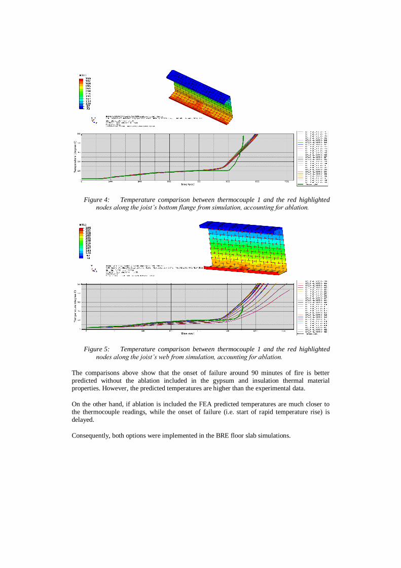
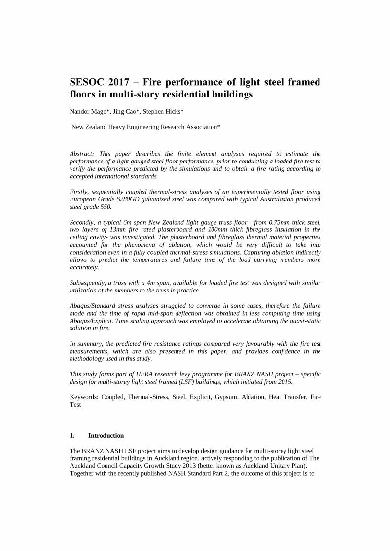
Figure 4: Temperature comparison between thermocouple 1 and the red highlighted nodes along the joist’s bottom flange from simulation, accounting for ablation.
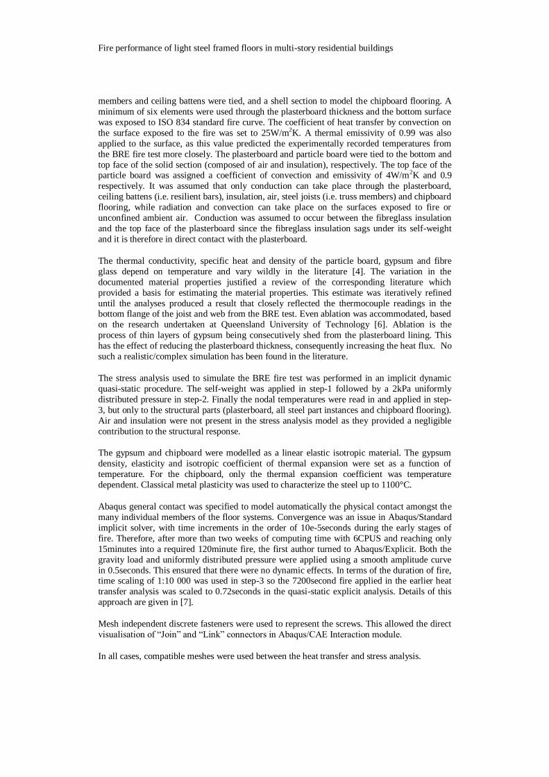
Figure 5: Temperature comparison between thermocouple 1 and the red highlighted
nodes along the joist’s web from simulation, accounting for ablation.
The comparisons above show that the onset of failure around 90 minutes of fire is better
predicted without the ablation included in the gypsum and insulation thermal material properties. However, the predicted temperatures are higher than the experimental data.
On the other hand, if ablation is included the FEA predicted temperatures are much closer to
the thermocouple readings, while the onset of failure (i.e. start of rapid temperature rise) is
delayed.
Consequently, both options were implemented in the BRE floor slab simulations.

Fire performance of light steel framed floors in multi-story residential buildings
Figure 6: Contour plot of vertical deflection for 90minutes of fire and floor centre
sagging with and without accounting for ablation in the FE model versus the
deflection recorded in the BRE fire test.
Figure 6 shows that the deflection is negligibly smaller for Grade 550 than for Grade 280. The
C shaped steel joists thickness was kept constant at 1.6mm in both cases. To that end, the
performance of the higher grade, New Zealand made steel subject to fire is directly comparable
to the lower strength European steel.
When accounting for ablation in the gypsum board and insulation material properties, as
recommended in [6], the slab centre node deflection became larger and the rapid increase in
deflection that is associated with the onset of failure occurred earlier in the fire. The grade of
steel had negligible influence on the simulation result, regardless of whether ablation was
included or not. Since Figure 6 shows that the limiting central deflection of the slab in fire is
reached earlier when ablation is considered, then to be conservative the typical New Zealand
light weight ceiling/floor was investigated based on ablation being included in the gypsum
board and fibreglass insulation material properties.
4. FEA of a typical truss floor
Based on the validated simulations presented above, the fire performance of a typical light steel
frame floor within an exemplar New Zealand multi-story building was investigated. The
modelling approach followed that described above, with minor variations. The National Association of Steel-Framed Housing Inc. (NASH) provided the data for a typical floor in
practice, which is as follows:
• 0.75mm thick Grade 550 steel, 350mm deep Frametek (FTK,
http://www.frametek.co.nz/) truss, spanning 6m and loaded with 2kPa uniformly
distributed pressure. The floor joists spacing is 600mm.
• 20mm thick particle board is screwed to the top chord of the truss. Rondo 311 clips
are fixed to the truss bottom chord, which hold the Gib Rondo 311D ceiling battens.
Two layers of 13mm fire rated plasterboards form the ceiling. 100mm thick fibreglass
insulation is placed between the steel trusses.
A 600mm wide strip from the floor with one FTK truss in the middle was modelled, with
symmetrical boundary conditions applied at the end planes of the 600mm tributary width. In
addition, only half of the span was modelled in both cases taking further advantage of
symmetry. Figure 7 shows the boundary conditions and the locations of the mesh independent
fasteners for the 6m span model.
Figure 7: The FE model showing the applied boundary conditions and fasteners.
The floor fire resistance was evaluated per AS 1530.4 [8]. There are three performance criteria:
1. Load bearing capacity –can be assessed by numerical simulations from:
a) Limiting deflection = L2/400d (mm); or
b) Limiting deflection rate = L2/9000d (mm/min)
where L is the clear span of the specimen in mm and d is the distance from the top of the
structural section to the bottom of the design tension zone in mm (d=350mm in this case).
2. Integrity – cannot be assessed by the simulations presented herein
3. Insulation - can be assessed by numerical simulations from:
a) Increase the average temperature above the initial average temperature by more than
140°C; or
b) Increase at any location above the initial average temperature by more than 180°C.
According to AS 1530.4, the rate of deflection criteria “shall not apply before a deflection of
L/30 is exceeded”.
In this particular case, the limiting deflection is 242.1mm (L=5822mm) while the deflection
rate is 10.8mm/min and is applicable after the centre of the floor sags by 194mm.
The FEA predicted that the limiting deflection criterion governs and failure occurs at
75minutes, as Figure 8 illustrates. Although the explicit solution is slightly dynamic (note the waviness in the deflection curve), the mid-span deflection is comparable to the solution
obtained using a much slower implicit solver. The mid-span deflection due to self-weight (step-

Fire performance of light steel framed floors in multi-story residential buildings
1) and 2kPa uniformly distributed pressure (end of step-2) is 23mm versus 25.5mm using the
implicit and explicit solver, respectively. Abaqus/Standard was left to pursue the fire solution
up to 935seconds (15.6minutes) where the deflection is 24.9mm (versus 26.5mm – explicit).
Figure 8: Deformed shape showing temperatures at 75minutes of fire (left) and the
history of mid-span deflection in multi-step analysis. Half model of 6m span.
5. FEA of BRANZ environment prior to fire test
A new truss was designed in preparation for the actual BRANZ fire test which uses a furnace with a clear span of 4m. The utilization of the main load carrying member in the fire test
should be comparable to the utilization in practice. In other words, it is expected that the
bending moment at the mid-span is identical in both cases. The bending moment (M) can be
calculated from basic structural engineering formulae for simply supported beams:
8
2qLM
where q is the uniformly distributed pressure and L is the span of the beam. The uniformly
distributed pressure should consequently be increased to maintain the bending moment when
reducing the span from 6m to 4m. Specifically, the relationship between the distributed load
that was applied to the 6m span (q1) and the distributed load applied to the 4m span (q2) is:
12
2
2
2
1
25.2
8
)4(
8
)6(
Thus 4.5kPa was applied on the top of the particle board for the 4m span. Since all materials
and thicknesses are identical to the 6m span model, this upscaling of the load is sufficient.
Abaqus/Explicit reduced integration shell (S4R) and solid (C3D8R) elements with enhanced
hourglass controls were employed to lessen the common numerical issue of “hourglassing”
(inability of a coarse mesh comprising linear reduced integration elements to represent bending
adequately). In addition, arbitrary Lagrangian-Eulerian (ALE) adaptive meshing of the
plasterboard helped to prevent excessive element distortion of some gypsum board elements
connected to the ceiling fasteners. These modifications enabled the simulation to reach the
limiting floor centre deflection, D=114.3mm (4m span). The 4m model used a mesh density for
the steel members that was similar to that used for the 6m model, and predicted that failure
would occur at 70.7minutes which is comparable to 75minutes predicted for the 6m span.
In the next stage of the project the combinations of actions for fire was investigated. According
to AS/NZS 1170.0 [10], for combinations of actions for fire: “The combination of factored
actions used when confirming the ultimate limit state for fire shall be as follows:
[G, thermal actions arising from the fire, ψl Q]”
where ψl =0.4 long-term factor for residential, domestic and office floors; G is the dead load
and Q is the live load (previously denoted by q). To be conservative, the long term-factor ψl
was not included in the numerical simulations presented above; however, it was included in the
subsequent BRANZ fire test. This meant that only 1.8kPa (=0.4 x 4.5kPa) of uniformly
distributed pressure was required. The limiting mid-span deflection of 114.3mm was reached at
73.2minutes of fire when subject to a 1.8kPa uniformly distributed pressure. The results
indicate that the floor is less sensitive to the applied load as its failure is governed by local
buckling of the bottom chord.
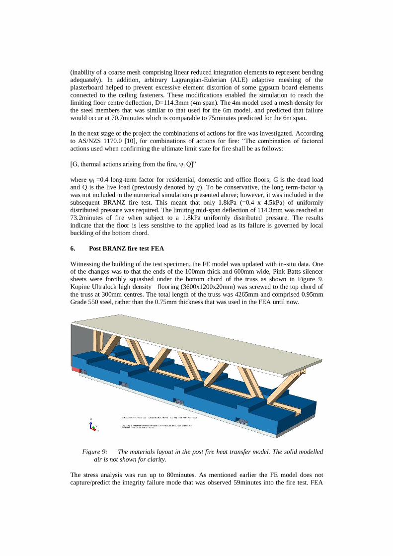
6. Post BRANZ fire test FEA
Witnessing the building of the test specimen, the FE model was updated with in-situ data. One of the changes was to that the ends of the 100mm thick and 600mm wide, Pink Batts silencer
sheets were forcibly squashed under the bottom chord of the truss as shown in Figure 9.
Kopine Ultralock high density flooring (3600x1200x20mm) was screwed to the top chord of
the truss at 300mm centres. The total length of the truss was 4265mm and comprised 0.95mm
Grade 550 steel, rather than the 0.75mm thickness that was used in the FEA until now.
Figure 9: The materials layout in the post fire heat transfer model. The solid modelled
air is not shown for clarity.
The stress analysis was run up to 80minutes. As mentioned earlier the FE model does not
capture/predict the integrity failure mode that was observed 59minutes into the fire test. FEA

Fire performance of light steel framed floors in multi-story residential buildings
predicts that the mid-span deflection of the floor (measured at the top of the particle board) is
3mm due to self-weight and 13.5mm when a live load of 1.8kPa is applied. This was not
recorded in the fire test. The comparison of mid-span deflection prior and after the fire test
shows that the simulations were conservative up to 58minutes.
Figure 10: Floor mid-span deflection comparison before and after the fire test.
Figure 11: Floor joists prior to be covered by particle boards.
-110
-90
-70
-50
-30
-10 0 10 20 30 40 50 60 70 80
DE
FLEC
TIO
N (m
m)
TIME (MIN)
Deflection of floor centre
TEST (F14) FEA-075mmPriorTest FEA-095mmAfterTest
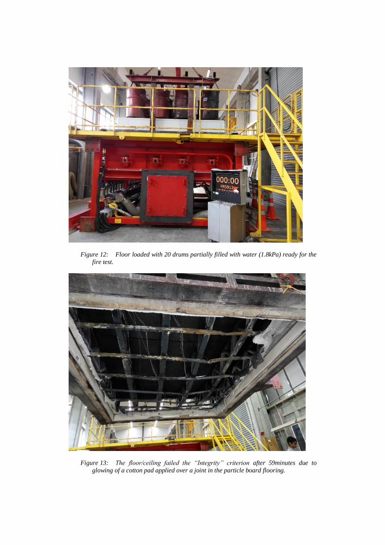
Figure 12: Floor loaded with 20 drums partially filled with water (1.8kPa) ready for the
fire test.
Figure 13: The floor/ceiling failed the “Integrity” criterion after 59minutes due to
glowing of a cotton pad applied over a joint in the particle board flooring.

Fire performance of light steel framed floors in multi-story residential buildings
7. Discussion and conclusion
This paper introduces the numerical modelling conducted by HERA for the fire performance of
a type of truss floor suitable for the future multi-storey LSF residential buildings in Auckland
region. This study completes part of two-year BRANZ NASH LSF project contracted to
HERA.
In this paper, a summary of FEA ranging from simple models (primarily used to calibrate
material properties) to complex models that directly reflect a floor system in fire are given. Adequate agreement was obtained between these numerical models and the results of the UK
BRE fire test. This was achieved following iterative manipulation and eventual fine tuning of
the temperature dependent material properties of the gypsum board and ceiling insulation. The
calibrated material data was subsequently used to predict the fire resistance rating (FRR) of a
typical 6m span light gauge steel truss and of the appropriately scaled 4m span truss prior to a
loaded fire test. An FRR of 75minutes and 69.7minutes was calculated for the 6m and 4m
spans, respectively, when subject to a full live load. In the corresponding BRANZ fire test the
live load was reduced by 60% as per AS/NZS 1170.0. The simulation with a reduced live load
of 1.8kPa predicted a fire resistance rating of 73.2minutes, which is approximately 3minutes
more than the FRR obtained when a live load of 4.5kPa was applied. Failure is governed by
local buckling of the open section of the bottom chord of the truss.
The sequentially coupled thermal-stress FEA were updated following the loaded fire tests to more precisely reflect the in-situ conditions. The integrity failure condition (the total failure of
the plasterboard whereby flames can observably penetrate through the floor) could not be
simulated. Regardless, the Abaqus simulations conservatively predicted the mid-span
deflection almost up to failure (58minutes into the fire).
The integrity failure condition of the floor/ceiling was observed 59minutes into the fire test.
Upon review of the test setup the plasterboard lining showed a 600mm long section where the
joins of the inner and outer layers of the plasterboard aligned. This may represent a typical case
in practice as minor mistakes inevitably occur. However, this location was where the
plasterboard started to fail and fall away from the truss during the fire test. Should the joints in
the outer layer have been consistently offset by 600mm from the joints in the inner layer in
both directions, it is felt by the author’s that the onset of failure would have most likely been postponed and the mid-span deflection recorded in the fire test would be closer to that
predicted by the FEA.

8. Acknowledgments
The financial support for this project was provided by the Building Research Levy (contract
LR0477), administered by the Building Research Association of New Zealand Inc. (BRANZ),
and by the New Zealand National Association of Steel Framed Housing Inc. (NASH). The
authors acknowledge with thanks the BRE fire test data that was provided by Prof. R.M.
Lawson of University of Surrey, UK. The data used in this paper are the intellectual property of
the New Zealand Heavy Engineering Research Association (HERA).
9. References
1. BS EN 1363-1:2012 Fire resistance tests, Part 1: General Requirements, Brussels, European Committee for Standardization.
2. 'Hot stuff' IPENZ, Engineering Insight, Volume 12/5, September/October 2011, pp. 16-
18.
3. Kankanamge ND, Mahendran M (2011), Mechanical properties of cold-formed steels at
elevated temperatures, Thin-Walled Structures, 49(1), pp. 26-44.
4. Fire resistance test in accordance with EN 1365-2:2000 on a light steel-framed loaded
floor (2008), Building Research Establishment (BRE) UK, Test report number 241607.
5. Abaqus Documentation 2014, Dessault Systèmes, Providence, RI, USA.
6. Poologanathan Keerthan, Mahen Mahendran, Thermal Performance of Composite
Panels under Fire Conditions Using Numerical Studies: Plasterboards, Rockwool, Glass Fibre and Cellulose Insulations, Faculty of Built in Environment and Engineering Queensland
University of Technology, Brisbane, QLD 4000, Australia.
7. Mago N, Hicks S, Simms WI (2014), Sequentially coupled thermal-stress analysis of a
new steel-concrete composite slab under fire, 2014 SIMULIA Customer Conference,
Providence, RI, USA.
8. AS 1530.4:2014 Methods for fire tests on building materials, components and structures
- Fire-resistance tests for elements of construction, Standards Australia.
9. Mago N. (2015), HERA Report R4-149: Fire performance of light steel framed floors in
multi-story residential buildings, New Zealand Heavy Engineering Research Association,
Auckland.
10. AS/NZS 1170.0:2002: Structural design actions - Part 0 General principles, Standards Australia/Standards New Zealand.