servoproportional valves type dlhzo-te and dlkzor...
TRANSCRIPT
www.atos.com
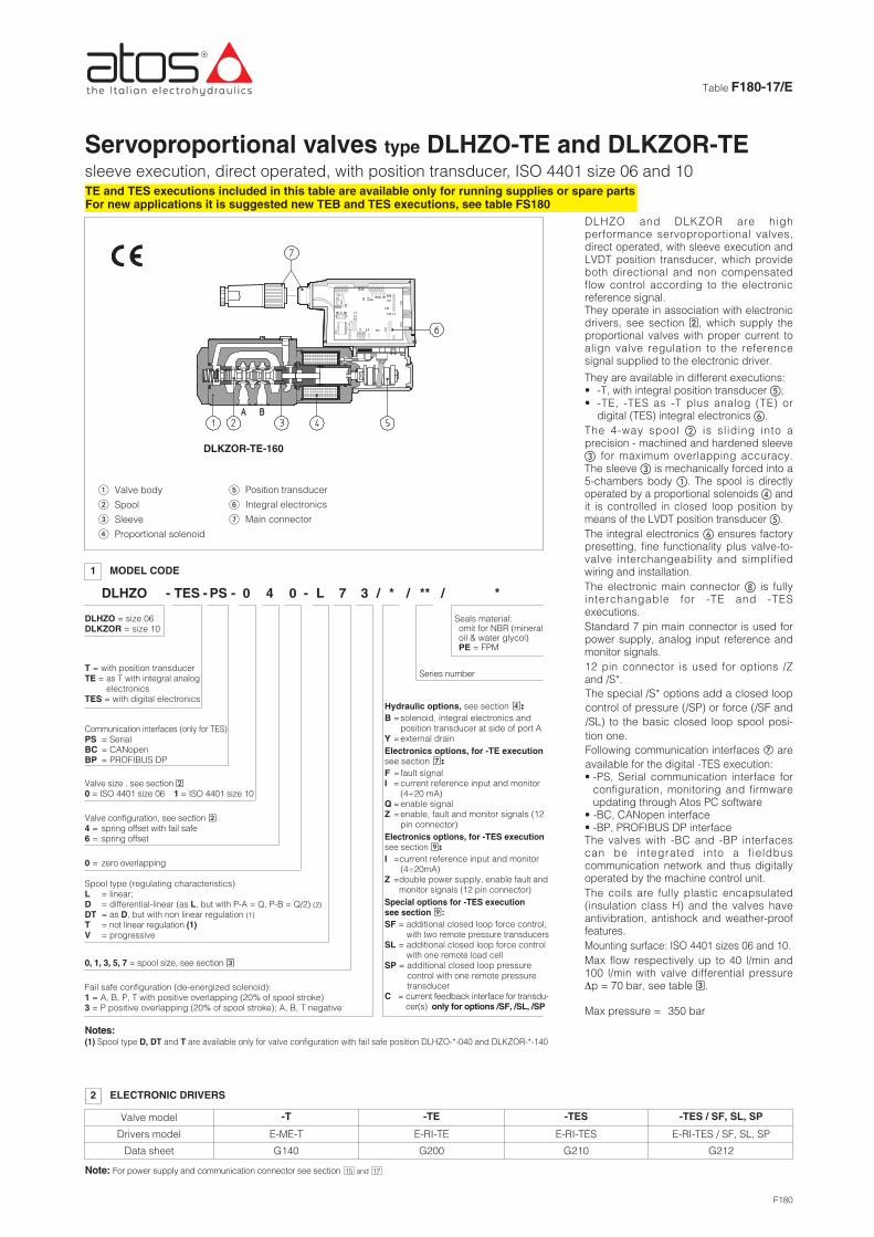
Servoproportional valves type DLHZO-TE and DLKZOR-TEsleeve execution, direct operated, with position transducer, ISO 4401 size 06 and 10
Table F180-17/E
1 MODEL CODE
DLKZOR-TE-160
DLHZO
DLHZO = size 06DLKZOR = size 10
T = with position transducerTE = as T with integral analog
electronicsTES = with digital electronics
Valve configuration, see section �4 = spring offset with fail safe6 = spring offset
0 = zero overlapping
0, 1, 3, 5, 7 = spool size, see section �
Notes:(1) Spool type D, DT and T are available only for valve configuration with fail safe position DLHZO-*-040 and DLKZOR-*-140
Fail safe configuration (de-energized solenoid):1 = A, B, P, T with positive overlapping (20% of spool stroke)3 = P positive overlapping (20% of spool stroke); A, B, T negative
Series number
TES PS 40 L-0 */7 3 ** / *- - -
Valve size , see section �0 = ISO 4401 size 06 1 = ISO 4401 size 10
Communication interfaces (only for TES)PS = SerialBC = CANopenBP = PROFIBUS DP
DLHZO and DLKZOR are highperformance servoproportional valves,direct operated, with sleeve execution andLVDT position transducer, which provideboth directional and non compensatedflow control according to the electronicreference signal. They operate in association with electronicdrivers, see section �, which supply theproportional valves with proper current toalign valve regulation to the referencesignal supplied to the electronic driver.
They are available in different executions:• -T, with integral position transducer �;• -TE, -TES as -T plus analog (TE) or
digital (TES) integral electronics �.The 4-way spool � is sl iding into aprecision - machined and hardened sleeve� for maximum overlapping accuracy.The sleeve � is mechanically forced into a5-chambers body �. The spool is directlyoperated by a proportional solenoids � andit is controlled in closed loop position bymeans of the LVDT position transducer �.The integral electronics � ensures factorypresetting, fine functionality plus valve-to-valve interchangeability and simplifiedwiring and installation.The electronic main connector � is fullyinterchangable for -TE and -TESexecutions.Standard 7 pin main connector is used forpower supply, analog input reference andmonitor signals.12 pin connector is used for options /Zand /S*.The special /S* options add a closed loopcontrol of pressure (/SP) or force (/SF and/SL) to the basic closed loop spool posi-tion one.Following communication interfaces � areavailable for the digital -TES execution:• -PS, Serial communication interface for
configuration, monitoring and firmwareupdating through Atos PC software
• -BC, CANopen interface• -BP, PROFIBUS DP interfaceThe valves with -BC and -BP interfacescan be integrated into a f ieldbuscommunication network and thus digitallyoperated by the machine control unit.The coils are fully plastic encapsulated(insulation class H) and the valves haveantivibration, antishock and weather-prooffeatures.Mounting surface: ISO 4401 sizes 06 and 10.Max flow respectively up to 40 l/min and100 l/min with valve differential pressureΔp = 70 bar, see table �.
Max pressure = 350 bar
Hydraulic options, see section �:B =solenoid, integral electronics and
position transducer at side of port AY =external drainElectronics options, for -TE executionsee section �:F =fault signalI =current reference input and monitor
(4÷20 mA)Q =enable signalZ =enable, fault and monitor signals (12
pin connector)Electronics options, for -TES executionsee section �:I =current reference input and monitor
(4÷20mA)Z =double power supply, enable fault and
monitor signals (12 pin connector)Special options for -TES execution see section �:SF = additional closed loop force control,
with two remote pressure transducersSL = additional closed loop force control
with one remote load cellSP = additional closed loop pressure
control with one remote pressuretransducer
C = current feedback interface for transdu-cer(s) only for options /SF, /SL, /SP
Spool type (regulating characteristics)L = linear; D = differential-linear (as L, but with P-A = Q, P-B = Q/2) (2)DT = as D, but with non linear regulation (1)T = not linear regulation (1)V = progressive
/
2 ELECTRONIC DRIVERS
Valve model
Data sheet
Drivers model E-ME-T
G140
-T
E-RI-TE
G200
-TE
E-RI-TES
G210
-TES
Note: For power supply and communication connector see section 15 and 17
Position transducer
Integral electronics
Main connector
�
�
�
Valve body
Spool
Sleeve
Proportional solenoid
�
�
�
�
F180
E-RI-TES / SF, SL, SP
G212
-TES / SF, SL, SP
Seals material:omit for NBR (mineraloil & water glycol)PE = FPM
TE and TES executions included in this table are available only for running supplies or spare partsFor new applications it is suggested new TEB and TES executions, see table FS180

2
Valve model
Pressure limits [bar]
DLHZO-T*
ports P, A, B = 350;
T = 210 (250 with external drain /Y)
3 HYDRAULIC CHARACTERISTICS (based on mineral oil ISO VG 46 at 50 °C)
DLKZOR-T*
ports P, A, B = 315;
T = 210 (250 with external drain /Y)
Spool
Leakage [cm3/min] at P = 100 bar (2)
Fail safe connections
Fail safe 1
Fail safe 3
DLHZO
DLKZOR Fail safe 3
Response time (5) [ms]
Hysteresis [%]
Thermal drift
≤ 10
≤ 0,1%
P → A P → B A → T B → T
50 70 70 50
50 70 - -
- - 15÷30 10÷20
- - 40÷60 25÷40
≤ 15
≤ 0,1%
Hydraulicsymbols
*60-L*1*60-V*1
b b
*60-L*1/B*60-V*1/B
a a a
b
zero point displacement < 1% at ΔT = 40°C
Signal description
OUTPUT SIGNAL
SUPPLY -15 VDC
SUPPLY +15 VDC
GND
PIN
1
2
3
4
POSITION TRANSDUCER CONNECTOR6 CONNECTIONS FOR -T EXECUTION
DLHZO and DLKZOR servoproportional valves are CE marked according to the applicable Directives (e.g. Immunity/Emission EMC Directive and Low Voltage Directive).
Installation, wirings and start-up procedures must be performed according to the general prescriptions shown in table F003 and in the installation notessupplied with relevant components.
The electrical signals of the valve (e.g. monitor signals) must not be directly used to activate safety functions, like to switch-ON/OFF the machine’s safetycomponents, as prescribed by the European standards (Safety requirements of fluid technology systems and components-hydraulics, EN-982).
Signal description
SUPPLY
SUPPLY
GND
PIN
1
2
3
SOLENOID POWER SUPPLY CONNECTOR
1
2 3
1
2
3
4
5 GENERAL NOTES
Standard driver execution provides on the 7 pin main connector:Power supply - 24VDC must be appropriately stabilized or rectified and filtered; a 2,5 A safety fuse is required in series to the driver power supply
Apply at least a 10000 μF/40 V capacitance to single phase rectifiers or a 4700 μF/40 V capacitance to three phase rectifiersReference input signal - analog differential input with ±10 VDC nominal range (pin D, E), proportional to desired valve spool positionMonitor output signal - analog output signal proportional to the actual valve’s spool position with ±10 VDC nominal rangeFollowing options are available to adapt standard execution to special application requirements:
7.1 Option /FIt provides a Fault output signal in place of the Monitor output signal, to indicate fault conditions of the driver (cable interruption of spool transducers orreference signal - for /I option): Fault presence corresponds to 0 VDC, normal working corresponds to 24 VDC.
7.2 Option /IIt provides the 4÷20 mA current reference and monitor signals instead of the standard ±10 VDCIt is normally used in case of long distance between the machine control unit and the valve or where the reference signal can be affected by electricalnoise; the valve functioning is disabled in case of reference signal cable breakage.
7.3 Option /QIt provides the possibility to enable or disable the valve functioning without cutting the power supply (the valve functioning is disabled but the driver cur-rent output stage is still active). To enable the driver supply a 24VDC on the enable input signal.
7.4 Option /ZThis option includes /F and /Q features, plus the Monitor output signal.When the driver is disabled (0 VDC on Enable signal) Fault output is forced to 0 VDC.
7.5 Possible combined options: /FI and /IZ
7 ANALOG INTEGRAL DRIVERS -TE - OPTIONS
4 HYDRAULIC OPTIONS
4.1 Option /B Solenoid, integral electronics and position transducer at side of port A.4.2 Option /Y External drain is mandatary if the pressure in port T exceeds 160 bar.
L0
Max flow (1) [l/min]at Δp = 30 barat Δp = 70 barmax permissible flow
2,548
L1 V1 L3 V3 L5 T5 L7 T7 V7 D7 DT7 L3 L7 T7 V7 D7 DT7
4,5714
5816
91430
132040
182850
264070
26÷1340÷2070÷40
406090
60100160
60÷33100÷50160÷80
Notes: Above performance data refer to valves coupled with Atos electronic drivers, see sections . The flow regulated by the directional proportional valves is not pressure compensated, thus it is affected by the load variations.To keep costant the regulated
flow under different load conditions, modular pressure compensators are available (see tab. D150).(1) For different Δp, the max flow is in accordance to the diagrams in section 13.2(2) Referred to spool in neutral position and 50°C oil temperature.(3) Referred to spool in fail safe position and 50°C oil temperature.(4) Referred to spool in fail safe position at Δp = 35 bar per edge and 50°C oil temperature.(5) 0-100% step signal
<200 <300 <500 <200 <900 <200 <1000 <1500 <400<100 <100 <150 <200 <200<700 <1200<400 <400
*40-L*3/B*40-D*3/B*40-DT*3/B*40-T*3/B*40-V*3/B
*40-L*1/B*40-D*1/B*40-DT*1/B*40-T*1/B*40-V*1/B
*40-L*3*40-D*3*40-DT*3*40-T*3*40-V*3
*40-L*1*40-D*1*40-DT*1*40-T*1*40-V*1
Leakage [cm3/min] at P = 100 bar (3)
Flow [l/min] (4)
9 DIGITAL INTEGRAL DRIVERS -TES - OPTIONS
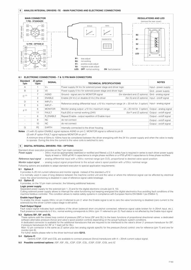
8 ANALOG INTEGRAL DRIVERS -TE - MAIN FUNCTIONS AND ELECTRONIC CONNECTIONS
12 PIN - OPTION /Z
REGULATIONS AND LED7 PIN - STANDARD
MAIN CONNECTOR
BIASSCALE
DIAGNOSTIC
B2
B1
S2
S1
bias adjust
LED:
�
�
��
LED�
(driv
er v
iew
)(d
river
vie
w)
8.1 ELECTRONIC CONNECTIONS - 7 & 12 PIN MAIN CONNECTORS
not workingpositive scale adjustnegative scale adjustOFF normal working; ON fault presence
B1:B2:S1:S2:
Standard driver execution provides on the 7 pin main connector:Power supply - 24VDC must be appropriately stabilized or rectified and filtered; a 2,5 A safety fuse is required in series to each driver power supply
Apply at least a 10000 μF/40 V capacitance to single phase rectifiers or a 4700 μF/40 V capacitance to three phase rectifiers
Reference input signal - analog differential input with ±10VDC nominal range (pin D,E), proportional to desired valve spool position
Monitor output signal - analog output signal proportional to the actual valve’s spool position with ±10VDC nominal range
Following options are available to adapt standard execution to special application requirements:
9.1 Option /IIt provides 4÷20 mA current reference and monitor signals instead of the standard ±10 V. It is normally used in case of long distance between the machine control unit and the valve or where the reference signal can be affected by electricalnoise; the valve functioning is disabled in case of reference signal cable breakage.
9.2 Option /ZIt provides, on the 12 pin main connector, the following additional features:Logic power supplySeparated power supply for the solenoid (pin 1, 2) and for the digital electronic circuits (pin 9, 10).Cutting solenoid power supply allows to interrupt the valve functioning but keeping energized the digital electronics thus avoiding fault conditions of themachine fieldbus controller. This condition allows to realize safety systems in compliance with European Norms EN13849-1 (ex EN954-1).
Enable Input Signal To enable the driver, supply 24VDC on pin 3 referred to pin 2: when the Enable signal is set to zero the valve functioning is disabled (zero current to thesolenoid) but the driver current output stage is still active.
Fault Output SignalFault output signal indicates fault conditions of the driver (solenoid short circuits/not connected, reference signal cable broken for 4÷20mA input, etc.).Fault presence corresponds to 0 VDC, normal working corresponds to 24VDC (pin 11 referred to pin 2): Fault status is not affected by the Enable input signal
9.3 Options /SP, /SF and /SLThese options add the closed loop control of pressure (/SP) or force (/SF and /SL) to the basic functions of proportional directional valves: a dedicatedsoftware alternates pressure (force) and valve’s spool position controls depending on the actual hydraulic system conditions. A dedicated connector is available for the additional transducers that are required to be interfaced to the valve’s driver (1 pressure transducer for /SP,2 pressure transducers for /SF or 1 load cell for /SL). Main 12 pin connector is the same as /Z option plus two analog signals specific for the pressure (force) control: one for reference (pin 7) and one formonitor (pin 8).For futher details please refer to the driver technical table G212.
9.4 Options /COptions /CSP, /CSF and /CSL are available to connect pressure (force) transducers with 4 ÷ 20mA current output signal.
9.5 Possible combined options: /ISP, /ISF, /ISL, /CSP, /CSF, /CSL, /CISP, /CISF, /CISL and /IZ
(remove the rear cover)
Standard7pin
/Z option12pin SIGNAL TECHNICAL SPECIFICATIONS NOTES
A 1 V+ Power supply 24 VDC for solenoid power stage and driver logic Input - power supply
Gnd - power supplyB 2 V0 Power supply 0 VDC for solenoid power stage and driver logic
C (1) 7 AGND Ground - signal zero for MONITOR signal (for standard and /Z options) Gnd - analog signal
3 ENABLE Enable (24 VDC) or disable (0 VDC) the driver (for /Q and /Z options) Input - on/off signal
D 4 INPUT+Reference analog differential input: ±10 VDC maximum range (4 ÷ 20 mA for /I option) Input - analog signal
E 5 INPUT -
F (2) 6 MONITOR Monitor analog output: ±10 VDC maximum range (4 ÷ 20 mA for /I option) Output - analog signal
11 FAULT Fault (0V) or normal working (24V) (for F and /Z options) Output - on/off signal
- 8 R_ENABLE Repeat Enable - output repetition of Enable input Output - on/off signal
- 9 NC do not connect Output - on/off signal
Output - on/off signal- 10 NC do not connect
G PE EARTH Internally connected to the driver housing
Notes (1) with /Q option ENABLE signal replaces AGND on pin C; MONITOR signal is reffered to pin B(2) with /F option FAULT signal replaces MONITOR on pin F. A minimum time of 50ms to 100ms have be considered between the driver energizing with the 24 VDC power supply and when the valve is readyto operate. During this time the current to the valve coils is switched to zero.
F180

10.2 ELECTRONIC CONNECTIONS - 5 PIN COMMUNICATION CONNECTORS
10.1 ELECTRONIC CONNECTIONS - 7 & 12 PIN MAIN CONNECTORS
-PS Serial -BC CANopen -BP PROFIBUS DPPIN SIGNAL TECHNICAL SPECIFICATION SIGNAL TECHNICAL SPECIFICATION SIGNAL TECHNICAL SPECIFICATION1 NC do not connect CAN_SHLD Shield +5V for termination2 NC do not connect NC do not connect LINE-A Bus line (high)3 RS_GND Signal zero data line CAN_GND Signal zero data line DGND data line and termination Signal zero 4 RS_RX Valves receiving data line CAN_H Bus line (high) LINE-B Bus line (low)5 RS_TX Valves transmitting data line CAN_L Bus line (low) SHIELD
Standard7pin
/Z option12pin SIGNAL TECHNICAL SPECIFICATIONS NOTES
A 1 V+ Power supply 24 VDC for solenoid power stage (and for driver logic on 7 pin connection) Input - power supply
Gnd - power supplyB 2 V0 Power supply 0 VDC for solenoid power stage (and for driver logic on 7 pin connection)
- 3 ENABLE Enable (24 VDC) or disable (0 VDC) the driver Input - on/off signal
D 4 INPUT+ Reference analog input: ±10 VDC maximum range (4 ÷ 20 mA for /I option)standard: differential input; /Z option: common mode INPUT+ referred to AGND
Input - analog signalE - INPUT -
C 5 AGNDGround - signal zero for MONITOR signal
signal zero for INPUT+ signal ( only for /Z option) Gnd - analog signal
F 6 MONITOR Monitor analog output: ±10 VDC maximum range (4 ÷ 20 mA for /I option) Output - analog signal
- 7 NC do not connect ( pressure/force input for /SP, /SF and /SL options, see 9.3 )
- 8 NC do not connect ( pressure/force monitor for /SP, /SF and /SL options, see 9.3 )
- 9 VL+ Power supply 24 VDC for driver logic Input - power supply
Gnd - power supply- 10 VL0 Power supply 0 VDC for driver logic
- 11 FAULT Fault (0V) or normal working (24V) Output - on/off signal
G PE EARTH Internally connected to the driver housing
10 DIGITAL INTEGRAL DRIVERS -TES - MAIN FUNCTIONS AND ELECTRONIC CONNECTIONS
COMMUNICATION CONNECTOR
12 PIN - OPTION /Z, /SP, /SF and /SL
7 PIN - STANDARD
5 PIN reverse keyPROFIBUS DP (-BP)
5 PIN Serial (-PS) orCANopen (-BC)
RAMPSBIASSCALE
LINEARIZATIONFIELDBUS
REFERENCEENHANCED
DIAGNOSTIC
REMOTE PRESSURE(FORCE) TRANDUCER(for /SP, /SF and /SL)
11 SOFTWARE TOOLS
MAIN CONNECTOR
Note: A minimum time of 300 to 500 ms have be considered between the driver energizing with the 24 VDC power supply and when the valve is readyto operate. During this time the current to the valve coils is switched to zero.
(driv
er v
iew
)(d
river
vie
w) (d
river
vie
w)
The driver configuration and parameters can be easily set with the Atos E-SW programming software, available in three different versions according to thedriver’s communication execution: E-SW-PS (Serial), E-SW-BC (CANopen) and E-SW-BP (PROFIBUS DP). For a more detailed description of software interface, PC requirements, adapters, cables and terminators, please refer to technical table G500.Programming software, must be ordered separately:E-SW-* (mandatory - first supply) = Dvd including E-SW-* software installer and operator manuals; it allows the registration to Atos digital serviceE-SW-*-N (optional - next supplies) = as above but not allowing the registration to Atos digital service
On first supply of the E-SW-* software, it is required to apply for the registration in the Atos download area: www.download.atos.com.Once the registration is completed, the password will be sent by email. The software remains active for 10 days from the installation date and then it stops until the user inputs his password. With the password you can also download, in your personal area, the latest releases of the Atos software, manuals, drivers and configuration files.
Assembly position Any positionSubplate surface finishing Roughness index Ra 0,4 - flatness ratio 0,01/100 (ISO 1101)Ambient temperature -20°C ÷ +70°C for -T execution; -20°C ÷ +60°C for -TE and TES executionsFluid Hydraulic oil as per DIN 51524 ... 535 for other fluids see section �Recommended viscosity 15 ÷100 mm2/s at 40°C (ISO VG 15÷100)Fluid contamination class ISO 4406 class 20/18/15 NAS 1638 class 9, in line filters of 10 μm (β10 _>75 recommended)Fluid temperature -20°C +60°C (standard seals and water glycol) -20°C +80°C (/PE seals)
12 MAIN CHARACTERISTICS OF PROPORTIONAL DIRECTIONAL VALVES
Valve model DLHZO-T* DLKZOR-T*Coil resistance R at 20°C 3 ÷ 3,3 Ω 3,8 ÷ 4,1 ΩMax. solenoid current 2,6 A 3 A Max. power 35 Watt 40 WattInsulation class H (180°) Due to the occuring surface temperatures of the solenoid coils, the European standards
ISO 13732-1 and EN982 must be taken into account
Protection degree (CEI EN-60529) IP65 for -T execution; IP67 for -TE and -TES executionsDuty factor Continuous rating (ED=100%)

13 DIAGRAMS (based on mineral oil ISO VG 46 at 50 °C)
13.1 Regulation diagrams
1 = Linear spools L2 = Differential - linear spool D7
F180
Nom
inal
flow
[%
]
Nom
inal
flow
[%
]
Reference signal [Volt] Reference signal [Volt]
1 2
3 = Differential non linear spool DT74 = Non linear spool T5 (only for DLHZO)
Nom
inal
flow
[%
]
Reference signal [Volt]
3
Note:Hydraulic configuration vs. reference signal:Standard:Reference signal 0 ÷+10 V P � A / B � T
12÷20 mA
Reference signal 0 ÷-10 V P � B / A � T4÷12 mA
option /B:Reference signal 0 ÷+10 V P � B / A � T
12÷20 mA
Reference signal 0 ÷-10 V P � A / B � T4÷12 mA
Nom
inal
flow
[%
]
Reference signal [Volt]
4
Nom
inal
flow
[%
]
Reference signal [Volt]
5
Nom
inal
flow
[%
]
Reference signal [Volt]
65 = Non linear spool T76 = Progressive spool V
7 = Pressure gain
Δp
A�
B [
%P
]
Spool stroke [%]
7
T5 and T7 spool types are specific for finelow flow control in the range from 0 to 60%(T5) and 0 to 40% (T7) of max spool stroke.The non linear characteristics of the spool iscompensated by the electronic driver, so thefinal valve regulation is resulting linearrespect the reference signal (dotted line).
DT7 has the same characteristic of T7 but itis specific for applications with cylinders witharea ratio 1:2
}}
}}

13.2 Flow /Δp diagramsStated at 100% of spool stroke
DLHZO:1 = spool L7, T7, V7, D7, DT72 = spool L5, T53 = spool V34 = spool L35 = spool L1, V16 = spool L0
DLKZOR:7 = spool L7, T7, V7, D7, DT78 = spool L3
13.3 Bode diagramsStated at nominal hydraulic conditions
DLHZO:1 = ± 100% nominal stroke2 = ± 5% nominal stroke
DLKZOR:3 = ± 100% nominal stroke4 = ± 5% nominal stroke
Flow
rat
e [l/
min
]
Valve pressure drop Δp [bar]
Flow
rat
e [l/
min
]
Valve pressure drop Δp [bar]
Am
plit
ude
ratio
[d
B]
Frequency [Hz]
Pha
se [
deg
ree]
Am
plit
ude
ratio
[d
B]
Frequency [Hz]
Pha
se [
deg
ree]
1 21 2
3 43 4
7
8
12
34
13.4 Dynamic response
The response times in section � have to be considered as average values.For the valves with digital electronics the dynamics performances can be optimized by setting the internal software parameters.
5
6

14 INSTALLATION DIMENSIONS [mm]
Mass: 2,8 kg
Mass: 2,3 kg
DLHZO-T
ISO 4401: 2005Mounting surface: 4401-03-02-0-05 (see table P005)(for /Y version, surface: 4401-03-03-0-05 without X port)Fastening bolts:4 socket head screws M5x50 class 12.9Tightening torque = 8 NmSeals: 4 OR 108; 1 OR 2025/70Diameter of ports A, B, P, T: Ø 7,5 mm (max)Diameter of port Y: Ø 3,2 mm (only for /Y option)
V
Mass: 2,8 kg
DLHZO-TE
DLHZO-TES
345666
Note: for option /B the solenoid and the position transducer are at side of port A
Dotted line =12 poles connector ZH-12P for option /Z
-TE EXECUTION
�
-TES EXECUTION��
ZH-7P or ZM-7P
�
�
�
ZH-5P/BP (for -BP)
ZH-5P (for -PS and -BC)ZH-7P or ZM-7P
Note: for option /B the solenoid, the position transducer and the integral electronics are at side of port A
345666
MODEL CODES OF POWER SUPPLY AND COMMUNICATION CONNECTORS (to be ordered separately)
VALVE VERSION
CONNECTOR CODE ZH-7P ZM-7P ZH-12P
PROTECTION DEGREE IP65
Power supply Transducer
IP65 IP67 IP67 IP67
-T -TE, -TES-TE/Z
-TES /Z, /SF, /SL, /SP
15
connectors supplied with the valve
DATA SHEET K500 G200, G210, K500
V = Air bleed off
Dotted line =12 pin connector ZH-12P for options /SF, /SL, /SP, /Z Dotted line = M8 connector ZH-4P-M8/5 moulded on cable 5 mt lenght for pressure or force transducer (options /SL, /SP)
M8 connector ZH-4P-M8/2-2 moulded with 2 cables, 2 mt lenght for 2 pressure transducers (options /SF)
(1) M8 connector ZH-4P-M8/5 moulded on cable 5 mt lenght for pressure or force transducer (options /SL, /SP)M8 connector ZH-4P-M8/2-2 moulded with 2 cables, 2 mt lenght for 2 pressure transducers (options /SF)
F180
ZH-5P ZH-5P/BP
IP67 IP67
serial (-PS)or CANopen (-BC)
PROFIBUS DP (-BP)
ZH-4P-M8/* (1)
IP67
TES /SF, /SL, /SP(transducer)
G210, K500 G212, K500
04/13
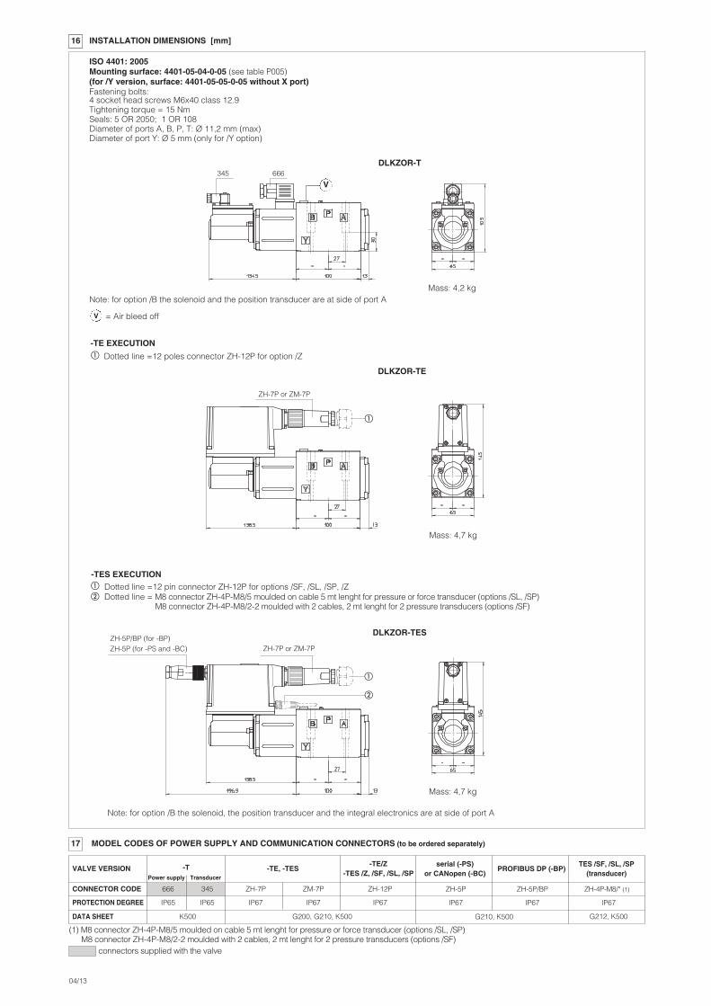
16 INSTALLATION DIMENSIONS [mm]
Mass: 4,7 kg
Mass: 4,2 kg
DLKZOR-T
DLKZOR-TES
ISO 4401: 2005Mounting surface: 4401-05-04-0-05 (see table P005)(for /Y version, surface: 4401-05-05-0-05 without X port)Fastening bolts:4 socket head screws M6x40 class 12.9Tightening torque = 15 NmSeals: 5 OR 2050; 1 OR 108Diameter of ports A, B, P, T: Ø 11,2 mm (max)Diameter of port Y: Ø 5 mm (only for /Y option)
V
DLKZOR-TE
Mass: 4,7 kg
345666
MODEL CODES OF POWER SUPPLY AND COMMUNICATION CONNECTORS (to be ordered separately)
VALVE VERSION
CONNECTOR CODE ZH-7P ZM-7P ZH-12P
PROTECTION DEGREE IP65
Power supply Transducer
IP65 IP67 IP67 IP67
-T -TE, -TES-TE/Z
-TES /Z, /SF, /SL, /SP
17
connectors supplied with the valve
DATA SHEET K500 G200, G210, K500
345 666
ZH-7P or ZM-7P
�
ZH-5P/BP (for -BP)ZH-5P (for -PS and -BC) ZH-7P or ZM-7P
�
�
Note: for option /B the solenoid and the position transducer are at side of port A
Dotted line =12 poles connector ZH-12P for option /Z
-TE EXECUTION
�
-TES EXECUTION��
Note: for option /B the solenoid, the position transducer and the integral electronics are at side of port A
(1) M8 connector ZH-4P-M8/5 moulded on cable 5 mt lenght for pressure or force transducer (options /SL, /SP)M8 connector ZH-4P-M8/2-2 moulded with 2 cables, 2 mt lenght for 2 pressure transducers (options /SF)
Dotted line =12 pin connector ZH-12P for options /SF, /SL, /SP, /Z Dotted line = M8 connector ZH-4P-M8/5 moulded on cable 5 mt lenght for pressure or force transducer (options /SL, /SP)
M8 connector ZH-4P-M8/2-2 moulded with 2 cables, 2 mt lenght for 2 pressure transducers (options /SF)
V = Air bleed off
ZH-5P ZH-5P/BP
IP67 IP67
serial (-PS)or CANopen (-BC)
PROFIBUS DP (-BP)
ZH-4P-M8/* (1)
IP67
TES /SF, /SL, /SP(transducer)
G210, K500 G212, K500