servo driven linear module - raco-international · comprised of a linear module, gear reducer, ......
TRANSCRIPT

SLMSERIESSERVO DRIVENLINEAR MODULE

THE SLM RODLESS LINEAR ACTUATOR
DESIGN FEATURES
RACO’S SLM line of linear positioning modules offersdesign versatility for any application requiring “cost effective” linear motion. The SLM design lends itself tostroke lengths of up to 235 inches and linear speeds up to 150 inch/sec. Two and three axis configurations may be easily and quickly implemented using the basic SLM module. Each system, comprised of a linear module, gear reducer, servo motor and servo amplifier, is pre-engineered
for selected speed and load capacities, as well as a properinertia match to provide a stable and robust system. Refer to the charts and graphs on pages 4-8 for a pre-engineered solution to your application requirements. The RACO LM Linear Module component is available for those customers who prefer to independently integrate drive-train
and control elements of theirown choice.
Features Benefits
■ Pre-engineered packaging Servo motor, amplifier and gear reducer sized for specific performance characteristics
■ Precision extruded body Allow stroke lengths to 235 inches
■ End of travel/home position sensors Over travel protection and home detection for complete position control
■ Polyurethane/steel reinforced belt Minimal stretch and high thrust capabilities
■ Cogged drive elements For thrusts up to 400 lbs. single and 800 lbs. double
■ Ball bearing carriage wheels For loads up to 600 lbs. single and 900 lbs. double
■ External belt adjustment Simple maintenance
■ Sealed wipers and bearings Long service life
■ T – Slots Facilitate mounting of SLM
2

3X-Y SYSTEM
USING A DOUBLE DRIVEN SLM AND
A SINGLE SLM
2DOUBLE DRIVEN SLM
1SINGLE DRIVEN SLM
4X-Y SYSTEM USINGDOUBLE DRIVENSLMs
5X-Y-Z SYSTEMMOVING BEAMSLMZ
3
VARIOUS USER CONFIGURATIONS

SLM3 SELECTION
Single Configuration
LOADTHRUST
Acceleration/Deceleration vs. Load
Lo
ad
(lb
s)
Time (sec.) Time (sec.)
Time (sec.) Time (sec.)
Solid Line = Full Thrust Dashed Line = NoThrust
Lo
ad
(lb
s)
Lo
ad
(lb
s)
Lo
ad
(lb
s)
6
4
2
0.1 0.2 0.3
24
16
8
0.1 0.2 0.3
90
60
30
0.1 0.2 0.3
450
300
150
0.2 0.4 0.6
A B
C D
4
Actuator Specification and Selection Chart
Model SLM3 SLM3 SLM3 SLM3Number A B C DMaximum 150"/sec. 100"/sec. 50"/sec. 25"/sec.SpeedMaximum 50 lbs. 80 lbs. 150 lbs. 300 lbs.ThrustMaximum 6 lbs. 24 lbs. 90 lbs. 450 lbs.Load (weight)Actuator Approximately 27 lbs. plus 0.325 lbs. per inch of strokeWeight

SLM3 SELECTION
Time (sec.) Time (sec.)
Time (sec.) Time (sec.)
18
12
6
0.1 0.2 0.3
90
60
30
0.1 0.2 0.3
450
300
150
0.2 0.4 0.6
750
500
250
0.3 0.6 0.9
E F
G H
Lo
ad
(lb
s)
Solid Line = Full Thrust Dashed Line = NoThrust
Lo
ad
(lb
s)
Lo
ad
(lb
s)
Lo
ad
(lb
s)
Double Configuration
LOADTHRUST
5
Actuator Specification and Selection Chart
Acceleration/Deceleration vs. Load
Model SLM3 SLM3 SLM3 SLM3Number E F G HMaximum 100"/sec. 50"/sec. 25"/sec. 15"/sec.SpeedMaximum 80 lbs. 150 lbs. 300 lbs. 500 lbs.ThrustMaximum 18 lbs. 90 lbs. 450 lbs. 750 lbs.Load (weight)Actuator Approximately 46 lbs. plus 0.65 lbs. per inch of strokeWeight
6
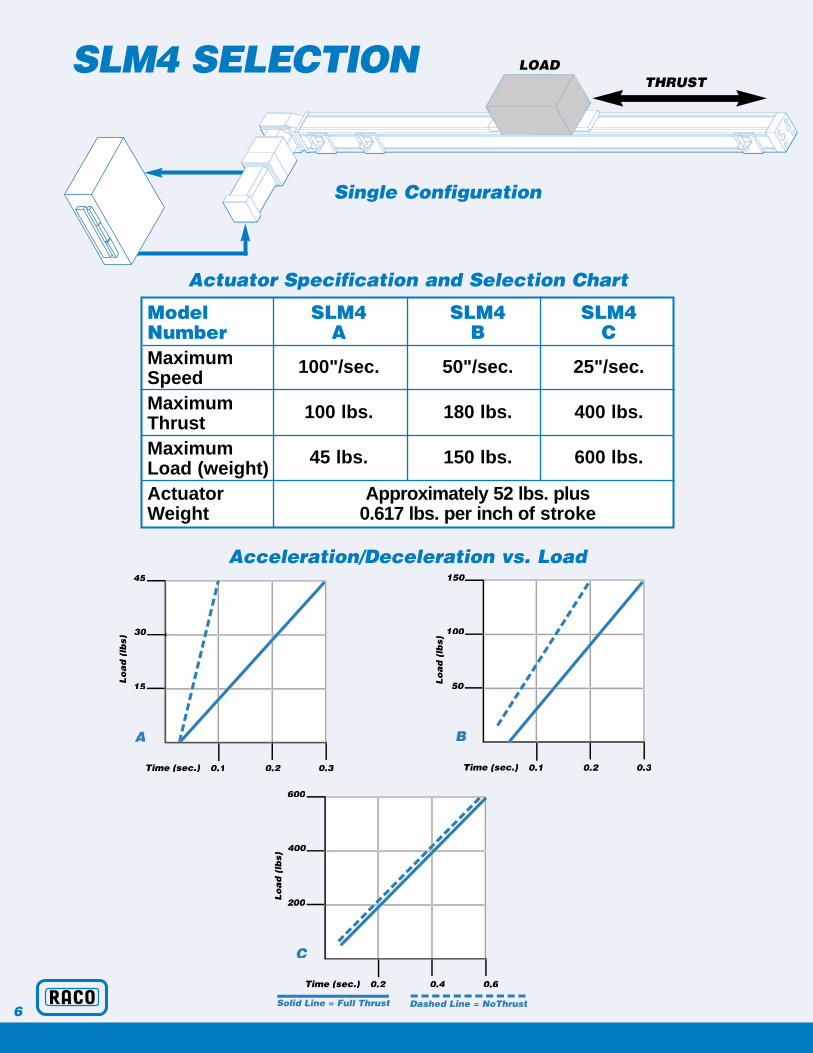
Acceleration/Deceleration vs. Load
Time (sec.) Time (sec.)
Time (sec.)
45
30
15
0.1 0.2 0.3
150
100
50
0.1 0.2 0.3
600
400
200
0.2 0.4 0.6
A B
C
Lo
ad
(lb
s)
Solid Line = Full Thrust Dashed Line = NoThrust
Lo
ad
(lb
s)
Lo
ad
(lb
s)
SLM4 SELECTION
Single Configuration
LOADTHRUST
Actuator Specification and Selection Chart
Model SLM4 SLM4 SLM4Number A B CMaximum 100"/sec. 50"/sec. 25"/sec.SpeedMaximum 100 lbs. 180 lbs. 400 lbs.ThrustMaximum 45 lbs. 150 lbs. 600 lbs.Load (weight)Actuator Approximately 52 lbs. plus Weight 0.617 lbs. per inch of stroke

7
Acceleration/Deceleration vs. Load
Time (sec.) Time (sec.)
Time (sec.)
150
100
50
0.1 0.2 0.3
600
400
200
0.2 0.4 0.6
900
600
300
0.3 0.6 0.9
D E
F
Lo
ad
(lb
s)
Solid Line = Full Thrust Dashed Line = NoThrust
Lo
ad
(lb
s)
Lo
ad
(lb
s)
SLM4 SELECTION
Double Configuration
LOADTHRUST
Actuator Specification and Selection Chart
Model SLM4 SLM4 SLM4Number D E FMaximum 50"/sec. 25"/sec. 12.5"/sec.SpeedMaximum 180 lbs. 400 lbs. 800 lbs.ThrustMaximum 150 lbs. 600 lbs. 900 lbs.Load (weight)Actuator Approximately 80 lbs. plus Weight 1.24 lbs. per inch of stroke

8
SLMZSELECTIONMOVING BEAM
EACH ENGINEEREDPACKAGE INCLUDES:
Time (sec.) Time (sec.)
30
20
10
0.1 0.2 0.3
60
40
20
0.1 0.2 0.3
Solid Line = Full Thrust Dashed Line = NoThrust
Lo
ad
(lb
s)
Lo
ad
(lb
s)
Acceleration/Deceleration vs. Load
TH
RU
ST
LOAD
Actuator Specification and Selection Chart
Switch SwitchHome
Switch
ServoMotor
PlanetaryGearReducer
Linear ModuleLoad Attachment Plate
OperationSoftware
ServoAmplifier
Model SLMZ SLMZNumber A BMaximum 20"/sec. 10"/sec.SpeedMaximum 100 lbs. 200 lbs.ThrustMaximum 30 lbs. 60 lbs.Load (weight)Maximum 36" 24"StrokeActuator Approximately 44 lbs. plus Weight 0.325 lbs. per inch of stroke
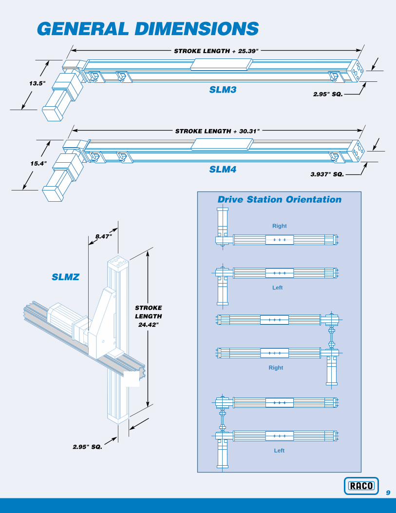
GENERAL DIMENSIONS
9
SLM3
SLM4
SLMZ
Drive Station Orientation
STROKE LENGTH + 30.31"
3.937" SQ.
Left
Right
Right
Left
15.4"
STROKE LENGTH + 25.39"
2.95" SQ.
13.5"
STROKELENGTH24.42"
2.95" SQ.
8.47"
•
••••
•••
◆
De
fle
cti
on
- i
n.
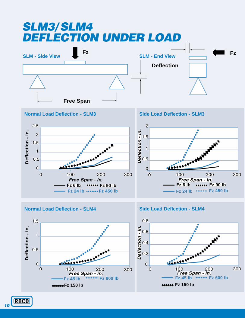
Fz 24 lb ••••••• Fz 450 lb
•
•••••
• •••
•
◆ ◆◆
◆◆
Fz 24 lb ••••••• Fz 450 lb
••
•••••
•••
•
◆ ◆
Fz 45 lb
◆◆◆◆◆◆
Fz 150 lb
•••••••
Fz 600 lb.
De
fle
cti
on
- i
n.
••••••• • •••
••••••
••
Fz 45 lb
◆◆◆◆◆◆ Fz 150 lb
•••••••
Fz 600 lb
••••••••
•••
•• ◆◆
◆◆◆•••
••••
➡
Fz Fz
➡
Free Span
Deflection
SLM3/SLM4 DEFLECTION UNDER LOADSLM - Side View
Normal Load Deflection - SLM3
Normal Load Deflection - SLM4
SLM - End View
Side Load Deflection - SLM3
Side Load Deflection - SLM4
10

SLM3/SLM4 TECHNICAL DATA
11
Data SLM3 SLM4
Input Power 230vac 3φFor operation on 115vac 1φ power
divide maximum speed shown on charts by 2
Repeatability +/- 0.003" +/- 0.003"Temperature Range -5° to +120° F -5° to +120° FMaximum Stroke 235" 233"
MaterialsStructure 6063 Al. AlloyBelt Polyurethane / steel reinforcedWheel Treads Delrin 150 SALink Shaft Solid or Tubular
Profile TolerancesFlatness 0.012" 0.016"Straightness 0.0125" per ft.Twist 0.25 degrees per ft. (3 degrees max.)
Belt Tension0" to 120" Stroke 90 lb. (6 lb-in) 110 lb. (9 lb-in)120" to 240" Stroke 180 lb. (12 lb-in) 210 lb. (15 lb-in)
For more than 45 years the name RACO has beenknown for high-quality electric cylinders aroundthe world. Based on our experience and on-going relationships with our customers we guarantee a reliable product using state of the art technology.RACO has the largest installed actuator base in theworld. The “RACO Electric Cylinder” has earned its position of world importance today as the replacement of pneumatic and hydraulic cylinders.RACO is located in Bethel Park, Pennsylvania with sales, manufacturing, engineering and administrative offices at the Bethel ParkHeadquarters.
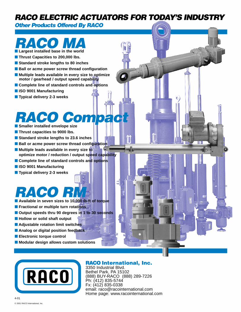
RACO International, Inc.3350 Industrial Blvd.Bethel Park, PA 15102(888) BUY-RACO (888) 289-7226Ph: (412) 835-5744Fx: (412) 835-0338email: [email protected] page: www.racointernational.com
© 2001 RACO International, Inc.
RACO ELECTRIC ACTUATORS FOR TODAY’S INDUSTRYOther Products Offered By RACO
RACO Compact■ Smaller installed envelope size
■ Thrust capacities to 9000 lbs.
■ Standard stroke lengths to 23.6 inches
■ Ball or acme power screw thread configuration
■ Multiple leads available in every size to optimize motor / reduction / output speed capability
■ Complete line of standard controls and options
■ ISO 9001 Manufacturing
■ Typical delivery 2-3 weeks
RACO RM■ Available in seven sizes to 10,000 lb-ft of torque
■ Fractional or multiple turn rotations
■ Output speeds thru 90 degrees in 1 to 30 seconds
■ Hollow or solid shaft output
■ Adjustable rotation limit switches
■ Analog or digital position feedback
■ Electronic torque control
■ Modular design allows custom solutions
RACO MA■ Largest installed base in the world
■ Thrust Capacities to 200,000 lbs.
■ Standard stroke lengths to 80 inches
■ Ball or acme power screw thread configuration
■ Multiple leads available in every size to optimizemotor / gearhead / output speed capability
■ Complete line of standard controls and options
■ ISO 9001 Manufacturing
■ Typical delivery 2-3 weeks
4-01