serviceability response of rehabilitated unbonded post
TRANSCRIPT
Journal of Rehabilitation in Civil Engineering 3-2 (2015) 16-29
journal homepage: http://civiljournal.semnan.ac.ir/
Serviceability Response of Rehabilitated Unbonded
Post-tensioned Indeterminate I-Beams Consisting
UHSSCC
M. Maghsoudi 1
and A.A. Maghsoudi 2*
1. Ph.D. Student, Civil Eng. Dept., Shahid Bahonar University of Kerman, Kerman, Iran.
2. Professor, Civil Eng. Dept., Shahid Bahonar University of Kerman, Kerman, Iran.
Corresponding author: [email protected]
ARTICLE INFO
ABSTRACT
Article history:
Received: 06 December 2015
Accepted: 15 June 2016
The ultra-high strength self-compacting concrete, UHSSCC
is the new generation type of concrete with a compressive
strength higher than 80MPa. The application of this type of
concrete on the serviceability state in CFRP strengthened
unbonded post-tensioned indeterminate I-beam is monitored
and the results are compared theoretically using different
standards. For this aim, full scale I-beam of 9m length was
cast, by UHSSCC. During the beam service load test, the
stress and strain of materials, and also deflection and crack
widths were monitored at different locations using different
types of sensors. Based on the experimental measurements
and observations, the beam serviceability response was
compared theoretically by different methods. As the
considerations prepared in the standards do not cover
strengthening of such members with unbonded tendons, and
also no trace of deflection prediction for such continuous
member, one can find in the open literature. It is therefore,
this investigation was planned. A comparison between
theoretical and monitored results was performed for
serviceability response and it was found that although, the
stress of materials are well within the standards limitations
for crack widths of 0.1 and 0.2 mm of bonded tendon, but the
full service load is reached at a higher load, while the
flexural crack, experience a width of 0.3 mm. It is also
apparent that the loads corresponding to the conventional
suggested deflection limits will cause to exceed
serviceability state of strengthened unbonded beam, and new
limitations are introduced for crack widths of 0.1, 0.2 and 0.3
mm to predict service deflection of beams.
Keywords:
Serviceability,
Unbonded post-tensioned,
Continuous beams,
UHSSCC,
Monitored.
1. Introduction Self-compacting concrete, SCC is relatively
new category of high performance concrete.
The mix is smooth enough that it freely
passes around and through the
reinforcements; it fills the formwork
17 M. Maghsoudi and A.A. Maghsoudi/ Journal of Rehabilitation in Civil Engineering 3-2 (2015) 16-29
completely and consolidates under its own
weight without segregation.
Ultra-high strength self-compacting concrete,
UHSSCC offers many advantages over
concrete constructions. The ultra-high
compressive strength can be used
advantageously in structures to reduce dead
load and subsequently to reduce total load on
the foundation system. The relatively higher
compressive strength per unit volume and per
unit weight will also significantly reduce the
dead load of flexural members.
When the strength of concrete gets higher,
some of its characteristics and engineering
properties become different from those of
normal-strength concrete, NSC [1, 2]. These
differences in material properties may have
important consequences in terms of the
structural behaviour and design of UHSSCC
members. The design provisions contained in
the major building codes are, in reality, based
on tests conducted on NSC. While designing
a structure using UHSSCC, the designer
particularly in the Southeast Asian region—
usually ignores the enhanced properties of
concrete and possible changes in the overall
response of the structure because of lack of
adequate code guidance [3] and so, this is the
worst when designing a structure using ultra
high strength concrete. Earlier research
concluded that although the tensile strength
increase with an increase in compressive
concrete strength, the serviceability stress in
tendons of unbonded post-tensioned
members are critical as the strain
compatibility is not apply due to to
prestressing tendons slip relative to the
surrounding concrete.
The calculation of unbonded tendon strain
generally requires a complicated procedure.
The procedure becomes more complicated
when the member even strengthened by
CRFP, tendon eccentricity changes with
applied loads etc., are included in the
analysis. Time dependent effects due to creep
and shrinkage of concrete and relaxation of
prestressed strands, and the effect due to
temperature gradient across the section depth
are important in the analysis to predict
accurate deflections, strains and stresses in
concrete structures at the serviceability limit
state.
It is important in the analysis that the
unbonded tendon stress be known due to
service loads to check the deflection and
crack width limitations. To determine the
strain in unbonded tendons due to the
different loading range, the structural
analysis has to be performed to find
displacements for the given loads. This
becomes difficult as the unbonded tendon
stresses are not known a priori, thus iterative
methods are generally required. Simplified
methods are also available to determine the
behavior of concrete structures with internal
unbonded tendons due to service loads
considering cracking. Most of these methods
are however limited to simply support non-
strengthened beams with symmetrical loads
and tendon profiles consisting of normal
(vibrated) concrete.
Advances in concrete technology in many
countries have now made practical use of
concrete (vibrated or non-vibrated, SCC)
with strengths up to 90 MPa. These
concretes, with very high compressive
strength, can result on the serviceability
responses of structural members especially
while considering the unbonded post-
tensioned tendons where, for such unbonded
tendons, the strain compatibility is not apply.
It has been found that a very limited research
works available while considering the
serviceability response in terms of maximum
deflection and flexural crack width
attainable, may be smaller in continuous
M. Maghsoudi and A.A. Maghsoudi/ Journal of Rehabilitation in Civil Engineering 3-2 (2015) 16-29 18
unbonded posttensioned rectangular beams
consisting of high strength vibrated concrete
strengthened by FRPs [4]. In daily service
life of structures, serviceability
considerations is an important factor in
design of UHSSCC members under flexure;
consequently the use of UHSSCC in
unbonded post-tensioned beams strengthened
with CFRP and serviceability that has not
been focus neither in Building Codes nor in
much of the limited previous experimental
research, will be focused in this study.
The failure modes of concrete beams
retrofitted with FRP materials and the
techniques used in analysing the failure
modes were reviewed by Toutanji et al. [5]
and Xiong et al. [6]. The behaviour of
concrete beams strengthened with externally
bonded steel plates, FRP plates, carbon fibre
fabric and GFRP sheets was studied both
experimentally and analytically. To date,
extensive research work has been conducted
on the flexural strength of concrete beams
bonded with various types of FRP
composites [7]. However, considering
implementation of ultra-high strength
concretes (i.e., NC and SCC) on
posttensioned continuous members, a few
research reports are available to consider the
effect of externally bonding FRP on the
unbonded tendon stress of such systems [8-
10].
The objective of this investigation is to study
the effectiveness of CFRP sheets and UHSSC
(f'c=95 MPa) on serviceability of full-scale
unbonded post-tensioned continuous I-beam
(L=9 m, bf =330 mm, bw =125 mm, hf =80
mm, h=400 mm). This objective is achieved
by conducting the following tasks: i) flexural
testing of unbonded post-tensioned UHSSC
continuous I-beam strengthened with CFRP
sheets reinforced with one unbonded tendon
and two tensile reinforcement bars of 18 mm
diameter; ii) monitoring the effect of
unbonded prestressing tendon, tensile bars
and CFRP sheets on the serviceability
response; iii) evaluating the flexural crack
width and height, and deflection.
Comparisons with theoretical model to
examine the monitored test beam behaviour
in serviceability considerations were also
performed.
2. Plastic phase properties and
results discussion
The continuous I-beam cast with the SCC
having an average compressive strength of
95 MPa in hardened state and the fresh phase
tests including: J ring, V funnel, L box and
slump flow were also carried out to check the
UHSSCC properties of mixes. The tests
results on plastic phase of SCC are shown in
Table 1. Evaluating the test results, the
precast/prestressed concrete institute (PCI)
guidelines for SCC [11] was considered as a
reference (Table 1), and it was concluded
that, the designed mix can be considered as
SCC in plastic phase and therefore it was
used to cast the post-tensioned I-beam.
3. Beam Detail, Instrumentation and
Test Procedure
The bending flexural test was conducted on
continuous unbonded post-tensioned ultra-
high strength self-compacting concrete I-
beam, strengthened by CFRP sheets named
as, SUPS1-18. The letters S, U, P and S, is
stand for strengthened, unbonded, post-
tensioned and self-compacting UHSC
respectively, and the number 1 and 18 are
indicated as one unbonded tendon of variable
eccentricity and 2 ordinary reinforced
19 M. Maghsoudi and A.A. Maghsoudi/ Journal of Rehabilitation in Civil Engineering 3-2 (2015) 16-29
Table 1. The results of tests on UHSSCC fresh concrete
V-
Funnel
(Sec.)
L-Box J-ring Slump flow
Mix T40
(Sec.)
T20
(Sec.) h2/h1
T50
(Sec.)
H
(cm)
dia.
(cm)
T50
(Sec.)
dia.
(cm)
6.3 3.1 1.4 0.84 3.3 0.45 69 2.8 71 SUPS1-18
6-12 -- -- 0.8-1
2-7 1.5≥ Same as
slump flow
-- 85-55 PCI (2003)
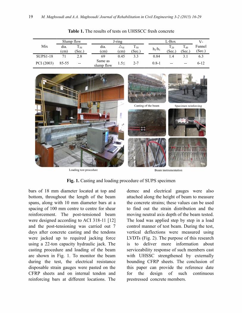
Fig. 1. Casting and loading procedure of SUPS specimen
bars of 18 mm diameter located at top and
bottom, throughout the length of the beam
spans, along with 10 mm diameter bars at a
spacing of 100 mm centre to centre for shear
reinforcement. The post-tensioned beam
were designed according to ACI 318-11 [12]
and the post-tensioning was carried out 7
days after concrete casting and the tendons
were jacked up to required jacking force
using a 22-ton capacity hydraulic jack. The
casting procedure and loading of the beam
are shown in Fig. 1. To monitor the beam
during the test, the electrical resistance
disposable strain gauges were pasted on the
CFRP sheets and on internal tendon and
reinforcing bars at different locations. The
demec and electrical gauges were also
attached along the height of beam to measure
the concrete strains; these values can be used
to find out the strain distribution and the
moving neutral axis depth of the beam tested.
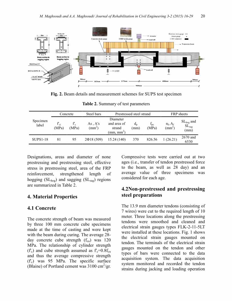
The load was applied step by step in a load
control manner of test beam. During the test,
vertical deflections were measured using
LVDTs (Fig. 2). The purpose of this research
is to deliver more information about
serviceability response of such members cast
with UHSSC strengthened by externally
bounding CFRP sheets. The conclusion of
this paper can provide the reference date
for the design of such continuous
prestressed concrete members.
M. Maghsoudi and A.A. Maghsoudi/ Journal of Rehabilitation in Civil Engineering 3-2 (2015) 16-29 20
Fig. 2. Beam details and measurement schemes for SUPS test specimen
Table 2. Summary of test parameters
Specimen
label
Concrete Steel bars Prestressed steel strand FRP sheets
f′ci
(MPa)
f′c
(MPa)
As , A′s
(mm2)
Diameter
and area of
strand
(mm, mm2)
dp
(mm)
fpe
(MPa)
nf, Af
(mm2)
SLhog and
SLsag
(mm)
SUPS1-18 81 95 2Φ18 (509) 15.24 (140) 370 826.56 1 (26.21) 2670 and
6530
Designations, areas and diameter of none
prestressing and prestressing steel, effective
stress in prestressing steel, area of the FRP
reinforcement, strengthened length of
hogging (SLhog) and sagging (SLsag) regions
are summarized in Table 2.
4. Material Properties
4.1 Concrete
The concrete strength of beam was measured
by three 100 mm concrete cube specimens
made at the time of casting and were kept
with the beam during curing. The average 28-
day concrete cube strength (fcu) was 120
MPa. The relationship of cylinder strength
(f'c) and cube strength assumed as f'c=0.8fcu
and thus the average compressive strength
(f'c) was 95 MPa. The specific surface
(Blaine) of Portland cement was 3100 cm2/gr.
Compressive tests were carried out at two
ages (i.e., transfer of tendon prestressed force
to the beam, as well as 28 day) and an
average value of three specimens was
considered for each age.
4.2Non-prestressed and prestressing
steel preparations
The 13.9 mm diameter tendons (consisting of
7 wires) were cut to the required length of 10
meter. Three locations along the prestressing
tendons were smoothed and cleaned and
electrical strain gauges types FLK-2-11-5LT
were installed at these locations. Fig. 1 shows
the electrical strain gauges mounted on
tendon. The terminals of the electrical strain
gauges mounted on the tendon and other
types of bars were connected to the data
acquisition system. The data acquisition
system monitored and recorded the tendon
strains during jacking and loading operation
21 M. Maghsoudi and A.A. Maghsoudi/ Journal of Rehabilitation in Civil Engineering 3-2 (2015) 16-29
to the computer system for further analysis
(Fig. 2). The tendon profile (laying pattern)
of the tendon consisting of variable tendon
eccentricity is presented in Eq. (1): 3 20.027 0.0822 0.0265 0.002 0 2.175
( )3 20.0661 0.6468 1.8759 1.53 2.175 4.3
x x x xe x
x x x x
(1)
The yield strength, ultimate strength, and
ultimate strain of the steel bars, and
prestressing strand are also listed in Table
(3).
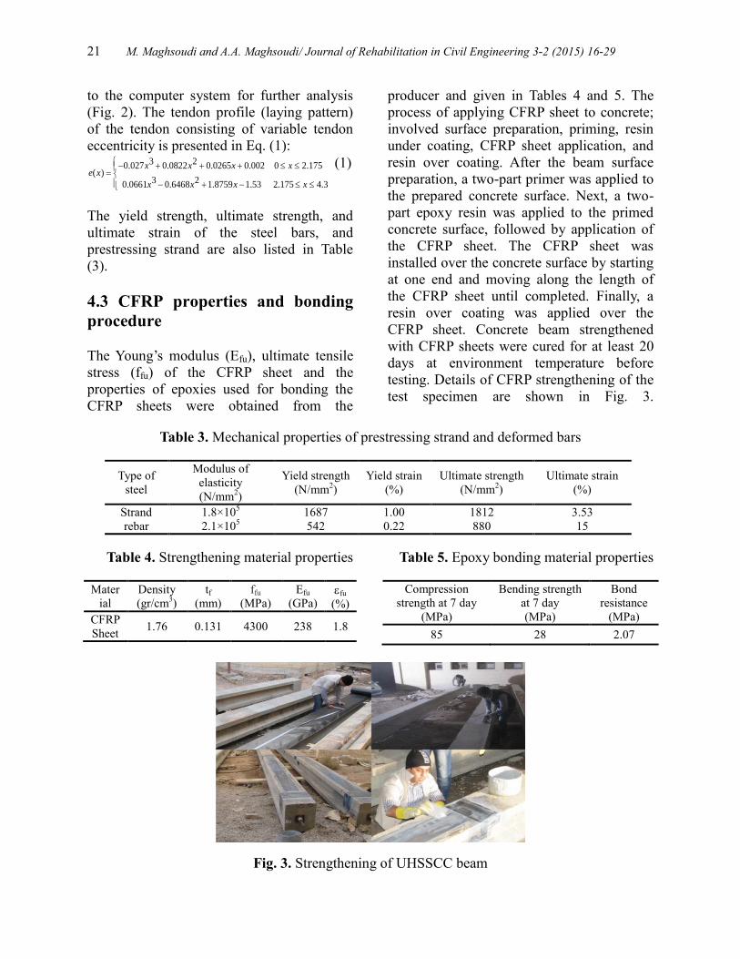
4.3 CFRP properties and bonding
procedure
The Young’s modulus (Efu), ultimate tensile
stress (ffu) of the CFRP sheet and the
properties of epoxies used for bonding the
CFRP sheets were obtained from the
producer and given in Tables 4 and 5. The
process of applying CFRP sheet to concrete;
involved surface preparation, priming, resin
under coating, CFRP sheet application, and
resin over coating. After the beam surface
preparation, a two-part primer was applied to
the prepared concrete surface. Next, a two-
part epoxy resin was applied to the primed
concrete surface, followed by application of
the CFRP sheet. The CFRP sheet was
installed over the concrete surface by starting
at one end and moving along the length of
the CFRP sheet until completed. Finally, a
resin over coating was applied over the
CFRP sheet. Concrete beam strengthened
with CFRP sheets were cured for at least 20
days at environment temperature before
testing. Details of CFRP strengthening of the
test specimen are shown in Fig. 3.
Table 3. Mechanical properties of prestressing strand and deformed bars
Ultimate strain
(%)
Ultimate strength
(N/mm2)
Yield strain
(%)
Yield strength
(N/mm2)
Modulus of
elasticity
(N/mm2)
Type of
steel
3.53 1812 1.00 1687 1.8×10⁵ Strand
15 880 0.22 542 2.1×10⁵ rebar
Table 4. Strengthening material properties
Mater
ial
Density
(gr/cm3)
tf
(mm)
ffu
(MPa)
Efu
(GPa) fu
(%)
CFRP
Sheet 1.76 0.131 4300 238 1.8
Table 5. Epoxy bonding material properties
Compression
strength at 7 day
(MPa)
Bending strength
at 7 day
(MPa)
Bond
resistance
(MPa)
85 28 2.07
Fig. 3. Strengthening of UHSSCC beam
M. Maghsoudi and A.A. Maghsoudi/ Journal of Rehabilitation in Civil Engineering 3-2 (2015) 16-29 22
5. Behavior of prestressed beams
under monotonic loads
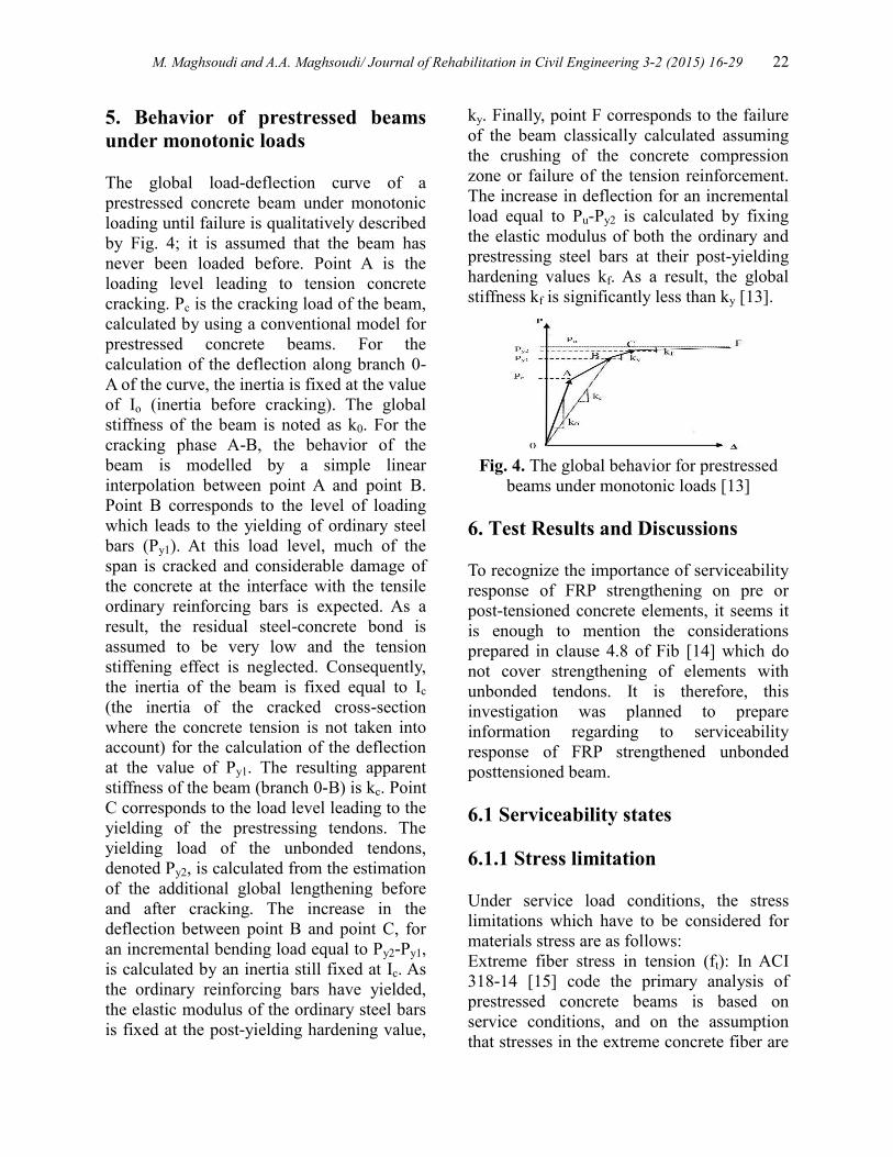
The global load-deflection curve of a
prestressed concrete beam under monotonic
loading until failure is qualitatively described
by Fig. 4; it is assumed that the beam has
never been loaded before. Point A is the
loading level leading to tension concrete
cracking. Pc is the cracking load of the beam,
calculated by using a conventional model for
prestressed concrete beams. For the
calculation of the deflection along branch 0-
A of the curve, the inertia is fixed at the value
of Io (inertia before cracking). The global
stiffness of the beam is noted as k0. For the
cracking phase A-B, the behavior of the
beam is modelled by a simple linear
interpolation between point A and point B.
Point B corresponds to the level of loading
which leads to the yielding of ordinary steel
bars (Py1). At this load level, much of the
span is cracked and considerable damage of
the concrete at the interface with the tensile
ordinary reinforcing bars is expected. As a
result, the residual steel-concrete bond is
assumed to be very low and the tension
stiffening effect is neglected. Consequently,
the inertia of the beam is fixed equal to Ic
(the inertia of the cracked cross-section
where the concrete tension is not taken into
account) for the calculation of the deflection
at the value of Py1. The resulting apparent
stiffness of the beam (branch 0-B) is kc. Point
C corresponds to the load level leading to the
yielding of the prestressing tendons. The
yielding load of the unbonded tendons,
denoted Py2, is calculated from the estimation
of the additional global lengthening before
and after cracking. The increase in the
deflection between point B and point C, for
an incremental bending load equal to Py2-Py1,
is calculated by an inertia still fixed at Ic. As
the ordinary reinforcing bars have yielded,
the elastic modulus of the ordinary steel bars
is fixed at the post-yielding hardening value,
ky. Finally, point F corresponds to the failure
of the beam classically calculated assuming
the crushing of the concrete compression
zone or failure of the tension reinforcement.
The increase in deflection for an incremental
load equal to Pu-Py2 is calculated by fixing
the elastic modulus of both the ordinary and
prestressing steel bars at their post-yielding
hardening values kf. As a result, the global
stiffness kf is significantly less than ky [13].
Fig. 4. The global behavior for prestressed
beams under monotonic loads [13]
6. Test Results and Discussions
To recognize the importance of serviceability
response of FRP strengthening on pre or
post-tensioned concrete elements, it seems it
is enough to mention the considerations
prepared in clause 4.8 of Fib [14] which do
not cover strengthening of elements with
unbonded tendons. It is therefore, this
investigation was planned to prepare
information regarding to serviceability
response of FRP strengthened unbonded
posttensioned beam.
6.1 Serviceability states
6.1.1 Stress limitation
Under service load conditions, the stress
limitations which have to be considered for
materials stress are as follows:
Extreme fiber stress in tension (ft): In ACI
318-14 [15] code the primary analysis of
prestressed concrete beams is based on
service conditions, and on the assumption
that stresses in the extreme concrete fiber are
23 M. Maghsoudi and A.A. Maghsoudi/ Journal of Rehabilitation in Civil Engineering 3-2 (2015) 16-29
limited to values that correspond to elastic
behavior. ACI defines three classes of
behaviors for prestressed flexural members.
Class U members are assumed to behave as
uncracked members. Class C members are
assumed to behave as cracked members. The
behavior of class T members is assumed to
be in transition between uncracked and
cracked. In other words, prestressed flexural
members shall be classified as class U, class
T, or class C based on ft, the computed
extreme fiber stress in tension in the
precompressed tensile zone calculated at
service loads, as follows (without any
suggestion for their corresponding flexural
crack width (wcr)):
( ) class U: f 0.62 (2)
( ) class T: 0.62 f 1.0 (3)
( ) class C: f 1.0 (4)
t c
c t c
t c
a f
b f f
c f
Extreme fiber stress in compression (fc): If
external tensile reinforcement is added and as
the compression force equals the total tensile
force, a significant change in the state of
concrete stress may be expected. To prevent
excessive compression, producing
longitudinal cracks and irreversible strains,
the following limitations (Eq. 5) are applied
for the concrete compressive stress based on
ACI-318 [15] without any suggestion for its
corresponding strain:
fc<0.45fc (5)
Noneprestressed and prestressing tendon
stress: Tensile stress in the steel under
serviceability conditions which could lead to
inelastic deformation of the steel shall be
avoided as this will lead to large and
permanently open cracks. This requirement
will be met provided that under service load,
the tensile stress in ordinary reinforcement
does not exceed 0.8fy [14]. Also the stress in
prestressing tendons should not exceed
0.75fpy (fpy=0.9fpu) after allowance for losses
[14].
FRP stress (ff): In a similar way, based on
ACI-440 [16], the FRP stress under service
load should be limited as Eq. (6):
ff<ffu (6)
where < 1 is the FRP stress limitation
coefficient. This coefficient depends on the
type of FRP and should be obtained through
experiments. Based on creep rupture tests,
indicative values of = 0.8, 0.5 and 0.3 may
be suggested for CFRP, AFRP and GFRP,
respectively.
6.1.2 Cracking propagation
Fig. 5 shows the service cracks propagation
and their development patterns of tested
SUPS1-18 beam, under the full service load.
Based on ACI-318 [15], the service load is
considered to be applied, when a
compressive stress of concrete at bottom
fiber of inner support section or top fiber of
mid-span section one, equals to 0.45fc (with
no recommendation for its corresponding
strain value). There are no any established
equations for obtaining the complete stress-
strain curves for UHSSCC and the
descending branch neither in ACI-363
standard [17] for high strength concrete nor
in ACI [15] standard, to model the
compressive stress-strain behavior of this
type of concrete. Therefore, based on Fib
[18] the stress-strain equation for high
strength concrete up to grade C120 as shown
in Eq. (7) was used for accessing the concrete
service stress and strain limitations while the
full service load is applied. So for tested
beam by substituting in Eq. (7), the
compressive strain of 0.001 is achieved for
the concrete service compression stress
limitation of 0.4fc. 2
c cm
k. -( )f (7)
1 (k-2).
where:
c = concrete compression stress
M. Maghsoudi and A.A. Maghsoudi/ Journal of Rehabilitation in Civil Engineering 3-2 (2015) 16-29 24
c = concrete compression strain
cmf = is compressive strength of standard
concrete cylindrical specimen at 28 days age
ciE = concrete modulus of elasticity equal to1/3
co E cmE [f 8 /10]
1 /c cm ciE f E 3
coE 20.5 10 MPa
c1 = strain at maximum compressive stress
equal to 0.25cm1.6 (f /10) /1000
ci c1k E / E
c c1/ is the plasticity number
E = the factor reflecting the effect of type of
aggregate on modulus of elasticity
The concrete was not initially pre-cracked
and the development of the cracks during the
test is highly influenced by the CFRP sheet.
Besides, for prestressed concrete, the
propagation of the cracks is not quasi-
instantaneous because of the prestressing
load, which acts against bending crack
propagation and widening. The first visible
cracking loads at inner support and two mid-
span regions are monitored and presented in
Table 6.
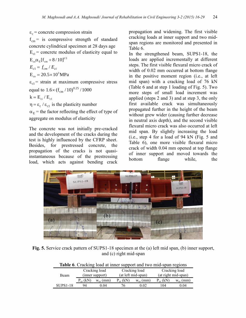
In the strengthened beam, SUPS1-18, the
loads are applied incrementally at different
steps. The first visible flexural micro crack of
width of 0.02 mm occurred at bottom flange
in the positive moment region (i.e., at left
mid span) with a cracking load of 76 kN
(Table 6 and at step 1 loading of Fig. 5). Two
more steps of small load increment was
applied (steps 2 and 3) and at step 3, the only
first available crack was simultaneously
propagated further in the height of the beam
without grew wider (causing further decrease
in neutral axis depth), and the second visible
flexural micro crack was also occurred at left
mid span. By slightly increasing the load
(i.e., step 4 for a load of 94 kN (Fig. 5 and
Table 6), one more visible flexural micro
crack of width 0.04 mm opened at top flange
of inner support and moved towards the
bottom flange while, the
Fig. 5. Service crack pattern of SUPS1-18 specimen at the (a) left mid span, (b) inner support,
and (c) right mid-span
Table 6. Cracking load at inner support and two mid-span regions
Beam
Cracking load
(inner support)
Cracking load
(at left mid-span)
Cracking load
(at right mid-span)
Pcr (kN) wcr (mm) Pcr (kN) wcr (mm) Pcr (kN) wcr (mm)
SUPS1-18 94 0.04 76 0.02 104 0.04
25 M. Maghsoudi and A.A. Maghsoudi/ Journal of Rehabilitation in Civil Engineering 3-2 (2015) 16-29
previous second crack which was occurred at
load step of 3 at left mid span, propagated
towards the web of I-beam without grew
wider in the first and second existing crack in
this region. At load increment of step 5 for a
load of 104 kN, without any propagation in
height of the beam for available cracks, two
more visible micro cracks were
simultaneously appeared at each bottom
flange of left and right mid spans consisting a
width of 0.04 and 0.03 mm at right and left
mid span respectively. However, at this step
of loading, no any new crack was occurred at
the inner support region (Fig. 5). On further
load increment of step 6, only 3 cracks were
occurred at top fiber of negative region and
were propagated further in the height of the
beam towards the bottom flange without
causing further decrease in neutral axis depth
for the only one existing crack of step 4
loading, but with grew wider in existing
crack (Fig. 5 and 6). At this step, the inner
support cracks reached a width of 0.3 mm
with a corresponding concrete stress and
strain of 0.45fc and 0.000945 (≈0.001)
respectively (i.e., the limitation of ACI-318
[15] for full service load) with a Load of 300
kN (Table 8). Therefore, for strengthened
beam, SUPS1-18 the full service load is also
considered to be reached at step 6 of loading,
while compressive stress of concrete at
bottom fiber of inner support section equals
to 0.45fc (as recommended in Eq. (7) by Fib
[18] or with a corresponding strain of 0.001).
Fig. 5 also illustrates that for full service
load, the number of cracks that occurred at
the left mid span were equal to that at the
inner support. The observed crack
propagation in SUPS1-18 is similar to past
research findings on RC [19] or bonded
prestressed concrete [20], due to unbonded
strands in rectangular unbonded
posttensioned strengthened beams.
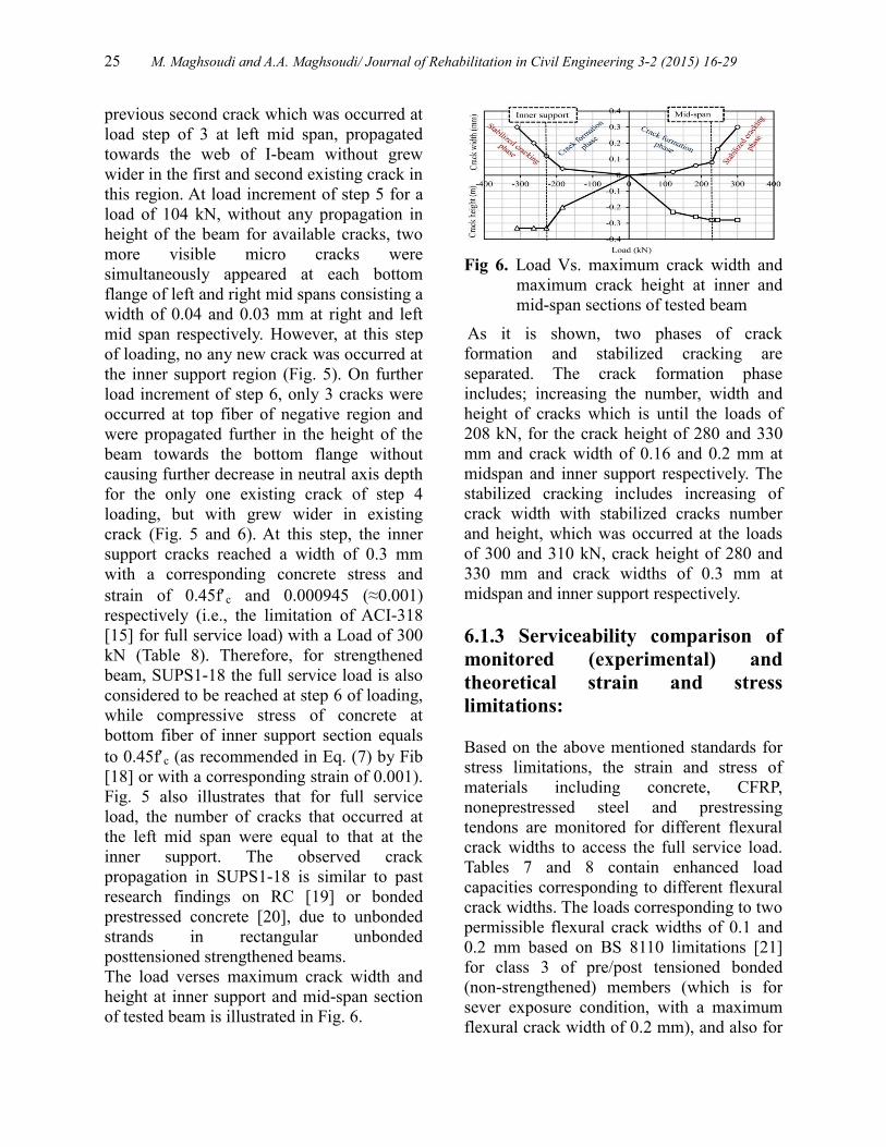
The load verses maximum crack width and
height at inner support and mid-span section
of tested beam is illustrated in Fig. 6.
Fig 6. Load Vs. maximum crack width and
maximum crack height at inner and
mid-span sections of tested beam
As it is shown, two phases of crack
formation and stabilized cracking are
separated. The crack formation phase
includes; increasing the number, width and
height of cracks which is until the loads of
208 kN, for the crack height of 280 and 330
mm and crack width of 0.16 and 0.2 mm at
midspan and inner support respectively. The
stabilized cracking includes increasing of
crack width with stabilized cracks number
and height, which was occurred at the loads
of 300 and 310 kN, crack height of 280 and
330 mm and crack widths of 0.3 mm at
midspan and inner support respectively.
6.1.3 Serviceability comparison of
monitored (experimental) and
theoretical strain and stress
limitations:
Based on the above mentioned standards for
stress limitations, the strain and stress of
materials including concrete, CFRP,
noneprestressed steel and prestressing
tendons are monitored for different flexural
crack widths to access the full service load.
Tables 7 and 8 contain enhanced load
capacities corresponding to different flexural
crack widths. The loads corresponding to two
permissible flexural crack widths of 0.1 and
0.2 mm based on BS 8110 limitations [21]
for class 3 of pre/post tensioned bonded
(non-strengthened) members (which is for
sever exposure condition, with a maximum
flexural crack width of 0.2 mm), and also for
M. Maghsoudi and A.A. Maghsoudi/ Journal of Rehabilitation in Civil Engineering 3-2 (2015) 16-29 26
0.1-0.3 mm width, which is usually based on
RC structural limitations for different
exposure classes, are presented to indicate
the trend of increasing crack width and
concrete, CFRP and two types of steel strain
to find out the full service load. It is clear that
materials including ordinary reinforcement,
prestressing tendon, concrete and CFRP
sheet, experienced stress values of 0.59fy and
0.81fy, 0.43fpy and 0.54fpy, 0.3f'c and 0.4f'c,
0.019ffu and 0.03ffu at mid-span and inner
support sections respectively, which are well
within the mentioned standards limitations
(0.8fy for ordinary rebar, 0.75fpy for
prestressing steel, 0.8ffu for CFRP and 0.4f'c
for concrete) at crack widths of 0.1, 0.2 and
0.3 mm. To encapsulate, the full service load
is reached at a higher load, while the flexural
crack, experienced a higher width of 0.3 mm.
BS [21] specifies the value of wcr to be 0.2
mm for bonded pre/posttensioned strands in
non-strengthened beams at full service load.
It can be seen that under full service load, the
higher value of wcr=0.3 mm, with an
enhancement ratio of γ=1.5 (wcr0.3/wcr0.2)
have been driven for strengthened
posttensioned unbonded beam of this study.
This founding is due to i) CFRP
strengthening ii) utilizing of UHSSCC and
iii) ordinary bonded bars, in unbonded
posttensioned member. As in practice, the
third factor is almost available in such
beams, therefore, the first two factor causes
to conclude that; in unbonded posttensioned
beam, it is possible to reach a new increase
flexural crack width of 0.3 mm while the full
service load is applied. In other words, these
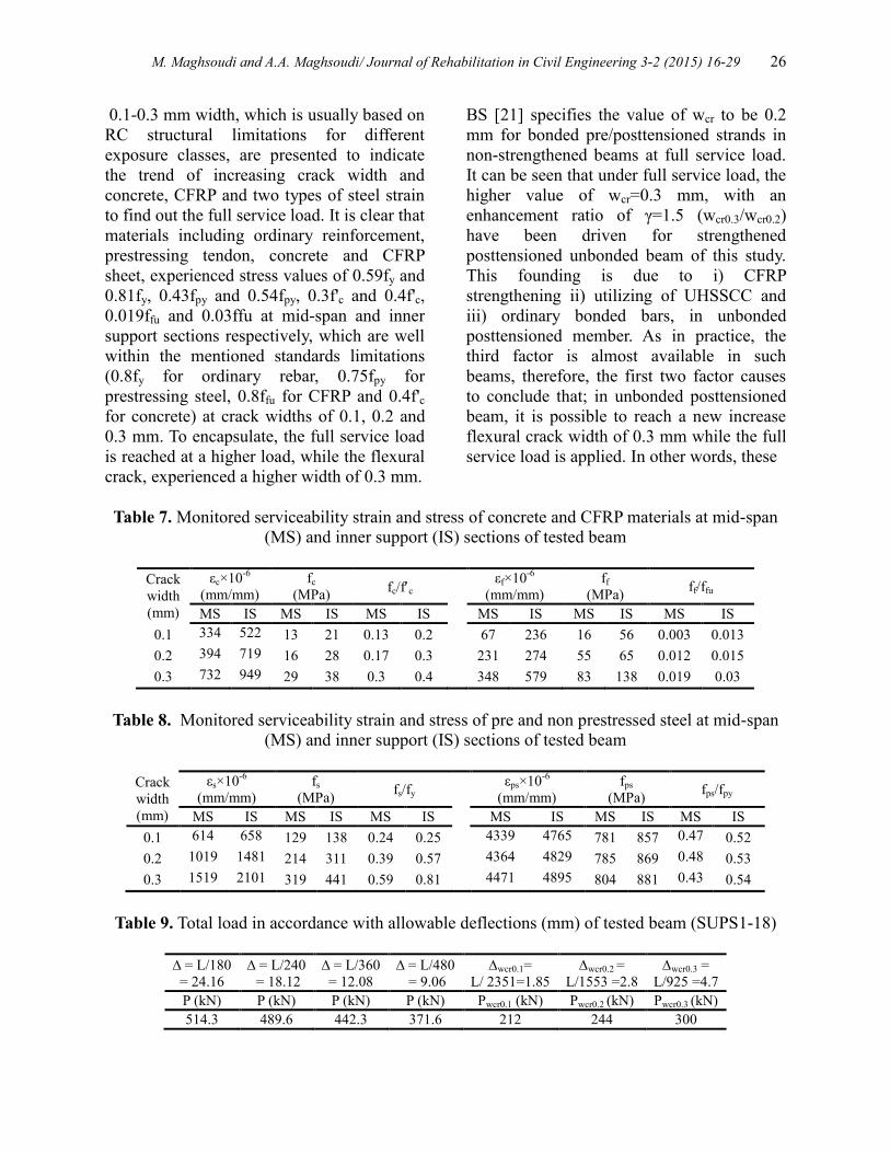
Table 7. Monitored serviceability strain and stress of concrete and CFRP materials at mid-span
(MS) and inner support (IS) sections of tested beam
Crack
width
(mm)
εc×10-6
(mm/mm)
fc
(MPa) fc/fc
εf×10-6
(mm/mm)
ff
(MPa) ff/ffu
MS IS MS IS MS IS MS IS MS IS MS IS
0.1 334 522 13 21 0.13 0.2 67 236 16 56 0.003 0.013
0.2 394 719 16 28 0.17 0.3 231 274 55 65 0.012 0.015
0.3 732 949 29 38 0.3 0.4 348 579 83 138 0.019 0.03
Table 8. Monitored serviceability strain and stress of pre and non prestressed steel at mid-span
(MS) and inner support (IS) sections of tested beam
Crack
width
(mm)
εs×10-6
(mm/mm)
fs
(MPa) fs/fy
εps×10-6
(mm/mm)
fps
(MPa) fps/fpy
MS IS MS IS MS IS MS IS MS IS MS IS
0.1 614 658 129 138 0.24 0.25 4339 4765 781 857 0.47 0.52
0.2 1019 1481 214 311 0.39 0.57 4364 4829 785 869 0.48 0.53
0.3 1519 2101 319 441 0.59 0.81 4471 4895 804 881 0.43 0.54
Table 9. Total load in accordance with allowable deflections (mm) of tested beam (SUPS1-18)
= L/180
= 24.16
= L/240
= 18.12
= L/360
= 12.08
= L/480
= 9.06
wcr0.1=
L/ 2351=1.85
wcr0.2 =
L/1553 =2.8
wcr0.3 =
L/925 =4.7
P (kN) P (kN) P (kN) P (kN) Pwcr0.1 (kN) Pwcr0.2 (kN) Pwcr0.3 (kN)
514.3 489.6 442.3 371.6 212 244 300
27 M. Maghsoudi and A.A. Maghsoudi/ Journal of Rehabilitation in Civil Engineering 3-2 (2015) 16-29
two factors, causes to increase the service
load even in unbonded posttensioned beam
which is beneficial and economy. However,
further tests on this subject are argent on both
strengthened and non-strengthened unbonded
post tensioned members, especially while
using self-compacting concretes.
It is also clear that, by strengthening the
unbonded posttensioned beam, the monitored
materials strain (Table 7 and 8) are well
below the service limitation strain as the
width of flexural crack moved from 0.1 mm
towards 0.2 mm.
6.2 Deflection response
The prestressed concrete member develops
deformation under the influence of two
usually opposing effects, which are the
prestress and transverse loads. The net
deflection of such members at any load stage
is obtained as Eq. (8):
Dnet=DL-Dp (8)
Where Dnet is the net deflection, DL is the
deflection due to self-weight and transverse
loading, and Dp the deflection due to
prestressing stress after allowance of the
losses, which is the effective prestressing
stress, fpe.
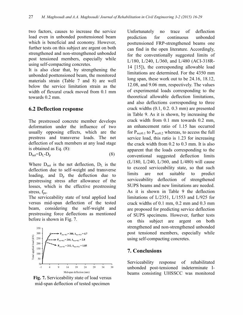
The serviceability state of total applied load
versus mid-span deflection of the tested
beam, considering the self-weight and
prestressing force deflections as mentioned
before is shown in Fig. 7.
Fig. 7. Serviceability state of load versus
mid-span deflection of tested specimen
Unfortunately no trace of deflection
prediction for continuous unbonded
posttensioned FRP-strengthened beams one
can find in the open literature. Accordingly,
for the conventionally suggested limits of
L/180, L/240, L/360, and L/480 (ACI-318R-
14 [15]), the corresponding allowable load
limitations are determined. For the 4350 mm
long span, these work out to be 24.16, 18.12,
12.08, and 9.06 mm, respectively. The values
of experimental loads corresponding to the
theoretical allowable deflection limitations,
and also deflections corresponding to three
crack widths (0.1, 0.2. 0.3 mm) are presented
in Table 9. As it is shown, by increasing the
crack width from 0.1 mm towards 0.2 mm,
an enhancement ratio of 1.15 has occurred
for Pwcr0.1 to Pwcr0.2 whereas, to access the full
service load, this ratio is 1.23 for increasing
the crack width from 0.2 to 0.3 mm. It is also
apparent that the loads corresponding to the
conventional suggested deflection limits
(L/180, L/240, L/360, and L/480) will cause
to exceed serviceability state, so that such
limits are not suitable to predict
serviceability deflection of strengthened
SUPS beams and new limitations are needed.
As it is shown in Table 9 the deflection
limitations of L/2351, L/1553 and L/925 for
crack widths of 0.1 mm, 0.2 mm and 0.3 mm
are proposed for predicting service deflection
of SUPS specimens. However, further tests
on this subject are argent on both
strengthened and non-strengthened unbonded
post tensioned members, especially while
using self-compacting concretes.
7. Conclusions
Serviceability response of rehabilitated
unbonded post-tensioned indeterminate I-
beams consisting UHSSCC was monitored
M. Maghsoudi and A.A. Maghsoudi/ Journal of Rehabilitation in Civil Engineering 3-2 (2015) 16-29 28
and compared theoretically and the following
conclusions are drawn:
Based on the above mentioned standards for
stress limitations, the strain and stress of
materials including concrete, CFRP, non-
prestressed steel and prestressing tendons are
monitored for three different flexural crack
widths of 0.1, 0.2 and 0.3 mm to access the
full service load of the beam.
The enhanced load capacities corresponding
to three flexural crack widths were found,
and for full service load, the higher value of
wcr=0.3 mm, with an enhancement ratio of
γ=1.5 (wcr0.3/wcr0.2) have been driven for
strengthened posttensioned unbonded beam.
This ratio is mainly due to i) CFRP
strengthening, and ii) utilizing of UHSSCC
in unbonded posttensioned member, and
cause to conclude that; by strengthening
unbonded posttensioned UHSSCC beam, it is
possible to reach a new increase flexural
crack width of 0.3 mm while the full service
load is applied, and therefore more beneficial
and economy is achievable. However, further
tests on this subject are argent.
The loads corresponding to two permissible
flexural crack widths of 0.1 and 0.2 mm
based on BS 8110 limitations for class 3 of
pre/post tensioned bonded (non-
strengthened) members (which is for sever
exposure condition, with a maximum flexural
crack width of 0.2 mm), are presented to
indicate the trend of increasing crack width
and concrete, CFRP and two types of steel
strain to find out the full service load. It was
found that, the stress of materials are well
within the mentioned standards limitations
for crack widths of wcr0.1 and wcr0.2, however
the full service load is reached at a higher
load, while the flexural crack, experience a
width of 0.3 mm.
In strengthened member, SUPS for all
permissible flexural crack widths, materials
strains were well below the allowable values.
It was also found that, the loads
corresponding to the conventional suggested
deflection limits will cause to exceed
serviceability state, so that such limits are not
suitable to predict serviceability deflection of
SUPS beams. Therefore, new deflection
limitations of L/2351, L/1553 and L/925 for
crack widths of 0.1 mm, 0.2 mm and 0.3 mm
are proposed for predicting service deflection
of such beams.
8. References
[1] CEB-FIP Model Code for structures. (1990).
“Comite-Euro international du
beton/federation internationale de la
precomtrainte”.
[2] ACI 209R. (1992). “Prediction of creep,
shrinkage and temperature effects in
concrete structures”. American Concrete
Institute, Farmington Hills, MI, USA.
[3] Rashid, M. A., Mansur, M. A., Paramasivam,
P. (2002). “Correlations between
Mechanical Properties of High-Strength
Concrete”. Journal of Materials in Civil
Engineering, Vol. 14, pp. 230-238.
[4] Ghasemi, S., Maghsoudi. A.A.,
Akbarzadeh.B., H., Ronagh, H.R. (2015).
“Sagging and hogging strengthening of
continuous unbonded posttensioned HSC
beams by NSM and EBR”. Journal of
Composite and Construction (ASCE), Vol.
20, pp. 04015056-1-13. [5] Toutanji, H., Zhao, L., Zhang, Y. (2006).
“Flexural behavior of reinforced concrete
beams externally strengthened with CFRP
sheets bonded with an inorganic matrix”.
Engineering Structures, Vol. 28, pp. 557-
566.
29 M. Maghsoudi and A.A. Maghsoudi/ Journal of Rehabilitation in Civil Engineering 3-2 (2015) 16-29
[6] Xiong, G.J., Jiang, X., Liu, J.W., Chen, L.
(2007). “A way for preventing tension
delamination of concrete cover in mid-
span of FRP strengthened beams”.
Construction and Building Materials, Vol.
21, pp. 402–408.
[7] Hashemi, H. (2007). “Study of reinforced
high strength concrete strengthened beams
by FRP”. PhD. Thesis, Civil Eng. Dept.,
Shahid Bahonar University of Kerman,
Kerman, Iran.
[8] Askari. D.Y., Maghsoudi, A.A. (2014).
“Monitoring and theoretical losses of post-
tensioned indeterminate I-beams”.
Magazine of Concrete Research, Vol. 66,
pp. 1-16.
[9] Askari. D.Y., Maghsoudi, A.A., (2014).
“Ultimate tendon stress in CFRP
strengthened unbonded HSC post-
tensioned continuous I-beams”. Journal of
Rehabilitation in Civil Engineering, Vol. 2,
pp. 35-45.
[10] Maghsoudi, A.A., Askari. D.Y. (2015).
“Ultimate unbonded tendon stress in
CFRP strengthened post-tensioned
indeterminate I-beams cast with HSCs”.
International Journal of Engineering,
Transactions C, Vol. 28, pp. 350-359.
[11] PCI. (2003). “Interim guidelines for the use
of self-consolidating concrete in
precast/prestressed concrete institute
member plants”. Chicago, IL, USA.
[12] ACI318R. (2011). “Building code
requirements for structural concrete and
commentary”. American Concrete
Institute, Farmington Hills, MI, USA.
[13] Vu., N.A., Castel., A., François., R. (2010).
“Response of post-tensioned concrete
beams with unbonded tendons including
serviceability and ultimate state”.
Engineering Structures, Vol. 32, pp. 556-
569.
[14] Fib. (2001). “Externally bonded FRP
reinforcement for RC structures”.
Technical Report Bulletin 14, Geneva,
Switzerland.
[15] ACI 318R-14. (2014). “Building code
requirements for structural concrete and
commentary”. American Concrete
Institute, Farmington Hills, MI, USA.
[16] ACI 440.2R. (2008). “Guide for the design
and construction of externally bonded FRP
systems for strengthening concrete
structures”. American Concrete Institute,
Detroit, MI, USA.
[17] ACI 363R. (2010). “State-of-the-art report
on high-strength concrete”. American
Concrete Institute, Farmington Hills, MI,
USA.
[18] Fib. (2008). “Constitutive modelling of high
strength high performance concrete”.
Technical Report Bulletin 42, Geneva,
Switzerland.
[19] Akbarzadeh B.H., Maghsoudi, A.A. (2009).
“Experimental investigations and
verification of debonding strain of RHSC
continuous beams strengthened in flexure
with externally bonded FRPs”. Journal of
Materials and Structures, Vol. 43 pp. 815-
837.
[20] Pellegrino, C., Modena, C. (2009). “Flexural
strengthening of real-scale RC and PRC
beams with end-anchored pretensioned
FRP laminates”. ACI Structural journal,
Vol. 106 pp. 319-328.
[21] BS 8110. (1997). “Structural use of
concrete”. Part 1, British Standards
Institution, London, UK.