service station manual - cadre cycle roamer - v9... · 2018-08-14 · service station manual v9...
TRANSCRIPT
SERVICE STATION MANUAL2Q000193
V9 Roamer - V9 Bobber

SERVICE STATIONMANUAL
V9 Roamer - V9 Bobber
THE VALUE OF SERVICEAs a result of continuous updates and specific technical training programmes for Moto Guzzi products,only Moto Guzzi Official Network mechanics know this vehicle fully and have the specific tools necessary
to carry out maintenance and repair operations correctly.The reliability of the vehicle also depends on its mechanical conditions. Checking the vehicle before ridingit, its regular maintenance and the use of original Moto Guzzi spare parts only are essential factors!
For information on the nearest Official Dealer and/or Service Centre consult our website:www.motoguzzi.com
Only by requesting Moto Guzzi original spare parts can you be sure of purchasing products that weredeveloped and tested during the actual vehicle design stage. All Moto Guzzi original spare parts undergo
quality control procedures to guarantee reliability and durability.The descriptions and images in this publication are given for illustrative purposes only and are not binding.While the basic characteristics as described and illustrated in this booklet remain unchanged, Piaggio &C. S.p.A. reserves the right, at any time and without being required to update this publication beforehand,to make any changes to components, parts or accessories, which it considers necessary to improve the
product or which are required for manufacturing or construction reasons.Not all versions/models shown in this publication are available in all countries. The availability of individual
versions should be checked with the Official Moto Guzzi sales network.The Moto Guzzi brand is owned by Piaggio & C. S.p.A.
© Copyright 2016 - Piaggio & C. S.p.A. All rights reserved. Reproduction of this publication in whole orin part is prohibited.
Piaggio & C. S.p.A. Viale Rinaldo Piaggio, 25 - 56025 PONTEDERA (PI), Italywww.piaggio.com

SERVICE STATION MANUALV9 Roamer - V9 Bobber
This manual provides the main information to carry out regular maintenance operations on your vehicle.This manual is intended to Moto Guzzi Dealers and their qualified mechanics; several concepts havebeen deliberately omitted as they are considered unnecessary. As it is not possible to include completemechanical notions in this manual, users should have basic mechanical knowledge or minimumknowledge about the procedures involved when repairing scooters. Without this knowledge, repairing orchecking the vehicle may be inefficient or even dangerous. As the vehicle repair and check proceduresare not described in detail, be extremely cautious so as not to damage components or injure individuals.In order to optimise customer satisfaction when using our vehicles, Moto Guzzi commits itself tocontinually improve its products and the relative documentation. The main technical modifications andchanges in repair procedures are communicated to all Moto Guzzi Sales Outlets and its InternationalSubsidiaries. These changes will be introduced in the subsequent editions of the manual. In case of needor further queries on repair and check procedures, consult Moto Guzzi CUSTOMER DEPARTMENT,which will be prepared to provide any information on the subject and any further communications onupdates and technical changes related to the vehicle.
NOTE Provides key information to make the procedure easier to understand and carry out.
CAUTION Refers to specific procedures to carry out for preventing damages to the vehicle.
WARNING Refers to specific procedures to carry out to prevent injuries to the repairer.
Personal safety Failure to completely observe these instructions will result in serious risk of personalinjury.
Safeguarding the environment Sections marked with this symbol indicate the correct use of the vehicleto prevent damaging the environment.
Vehicle intactness The incomplete or non-observance of these regulations leads to the risk of seriousdamage to the vehicle and sometimes even the invalidity of the guarantee


INDEX OF TOPICS
CHARACTERISTICS CHAR
SPECIAL TOOLS S-TOOLS
MAINTENANCE MAIN
ELECTRICAL SYSTEM ELE SYS
ENGINE FROM VEHICLE ENG VE
ENGINE ENG
POWER SUPPLY P SUPP
SUSPENSIONS SUSP
CHASSIS CHAS
BRAKING SYSTEM BRAK SYS
BODYWORK BODYW
PRE-DELIVERY PRE DE

INDEX OF TOPICS
CHARACTERISTICS CHAR

Rules
Safety rules
Carbon monoxide
If you need to keep the engine running while working on the vehicle, please ensure that you do so in
an open or very well ventilated area. Never run the engine in an enclosed area. If you do work in an
enclosed area, make sure to use a fume extraction system.CAUTION
EXHAUST EMISSIONS CONTAIN CARBON MONOXIDE, A POISONOUS GAS WHICH CAN CAUSELOSS OF CONSCIOUSNESS AND EVEN DEATH.FuelCAUTION
THE FUEL USED TO POWER INTERNAL COMBUSTION ENGINES IS HIGHLY FLAMMABLE ANDMAY BE EXPLOSIVE UNDER CERTAIN CONDITIONS. IT IS THEREFORE RECOMMENDED TOCARRY OUT REFUELLING AND MAINTENANCE PROCEDURES IN A VENTILATED AREA WITHTHE ENGINE SWITCHED OFF. DO NOT SMOKE DURING REFUELLING AND NEAR FUEL VA-POURS, AVOIDING ANY CONTACT WITH NAKED FLAMES, SPARKS OR OTHER SOURCESWHICH MAY CAUSE THEM TO IGNITE OR EXPLODE.DO NOT DISPERSE FUEL IN THE ENVIRONMENT.KEEP OUT OF THE REACH OF CHILDRENHot components
The engine and the exhaust system components become very hot and remain hot for some time after
the engine has been switched off. When handling these components, wear insulating gloves or wait
until the engine and the exhaust system have cooled down.
Used engine oil and transmission oilCAUTION
IT IS ADVISABLE TO WEAR PROTECTIVE IMPERMEABLE GLOVES WHEN SERVICING THE VE-HICLE.THE ENGINE OR GEARBOX OIL MAY CAUSE SERIOUS INJURIES TO THE SKIN IF HANDLEDFOR PROLONGED PERIODS OF TIME AND ON A REGULAR BASIS.WASH YOUR HANDS CAREFULLY AFTER HANDLING OIL.HAND THE OIL OVER TO OR HAVE IT COLLECTED BY THE NEAREST USED OIL RECYCLINGCOMPANY OR THE SUPPLIER.DO NOT DISPOSE OF OIL IN THE ENVIRONMENTKEEP OUT OF THE REACH OF CHILDREN
V9 Roamer - V9 Bobber Characteristics
CHAR - 7
Brake and clutch fluid
BRAKE AND CLUTCH FLUIDS CAN DAMAGE THE PLASTIC OR RUBBER PAINTED SURFACES.WHEN SERVICING THE BRAKING SYSTEM OR THE CLUTCH SYSTEM, PROTECT THESE COM-PONENTS WITH A CLEAN CLOTH. ALWAYS WEAR PROTECTIVE GOGGLES WHEN SERVICINGTHESE SYSTEMS. BRAKE AND CLUTCH FLUIDS ARE EXTREMELY HARMFUL FOR YOUREYES. IN THE EVENT OF ACCIDENTAL CONTACT WITH THE EYES, RINSE THEM IMMEDIATELYWITH ABUNDANT COLD, CLEAN WATER AND SEEK MEDICAL ADVICE.KEEP OUT OF THE REACH OF CHILDREN
Battery electrolyte and hydrogen gasCAUTION
THE BATTERY ELECTROLYTE IS TOXIC, CORROSIVE AND AS IT CONTAINS SULPHURIC ACID,IT CAN CAUSE BURNS WHEN IN CONTACT WITH THE SKIN. WHEN HANDLING BATTERYELECTROLYTE, WEAR TIGHT-FITTING GLOVES AND PROTECTIVE APPAREL. IN THE EVENTOF SKIN CONTACT WITH THE ELECTROLYTIC FLUID, RINSE WELL WITH PLENTY OF CLEANWATER. IT IS PARTICULARLY IMPORTANT TO PROTECT YOUR EYES BECAUSE EVEN TINYAMOUNTS OF BATTERY ACID MAY CAUSE BLINDNESS. IF THE FLUID GETS IN CONTACT WITHYOUR EYES, WASH WITH ABUNDANT WATER FOR FIFTEEN MINUTES AND CONSULT AN EYESPECIALIST IMMEDIATELY. THE BATTERY RELEASES EXPLOSIVE GASES; KEEP IT AWAYFROM FLAMES, SPARKS, CIGARETTES OR ANY OTHER HEAT SOURCES. ENSURE ADE-QUATE VENTILATION WHEN SERVICING OR RECHARGING THE BATTERY.KEEP OUT OF THE REACH OF CHILDRENBATTERY LIQUID IS CORROSIVE. DO NOT POUR IT OR SPILL IT, PARTICULARLY ON PLASTICCOMPONENTS. ENSURE THAT THE ELECTROLYTIC ACID IS COMPATIBLE WITH THE BAT-TERY TO BE ACTIVATED.
Maintenance rules
GENERAL PRECAUTIONS AND INFORMATION
When repairing, dismantling and reassembling the vehicle follow the recommendations reported below
carefully.
BEFORE REMOVING COMPONENTS
• Before dismantling components, remove dirt, mud, dust and foreign bodies from the vehicle.
Use the special tools designed for this bike, as required.
COMPONENTS REMOVAL
• Do not loosen and/or tighten screws and nuts using pliers or any other tools than the specific
wrench.
• Mark the positions on all connection joints (pipes, cables, etc.) before separating them, and
identify them with different distinctive symbols.
• Each component needs to be clearly marked to enable identification during reassembly.
• Clean and wash the dismantled components carefully using a low-flammability detergent.
• Keep mated parts together since they have "adjusted" to each other due to normal wear.
Characteristics V9 Roamer - V9 Bobber
CHAR - 8

• Some components must be used together or replaced altogether.
• Keep away from heat sources.
REASSEMBLY OF COMPONENTSCAUTIONBEARINGS MUST BE ABLE TO ROTATE FREELY, WITHOUT JAMMING AND/OR NOISE: OTH-ERWISE, THEY NEED TO BE REPLACED.
• Only use ORIGINAL Moto Guzzi SPARE PARTS.
• Comply with lubricant and consumables use guidelines.
• Lubricate parts (whenever possible) before reassembling them.
• When tightening nuts and screws, start from the ones with the largest section or from the
internal ones, moving diagonally. Tighten nuts and screws in successive steps before ap-
plying the tightening torque.
• Always replace self-locking nuts, washers, sealing rings, circlips, O-rings (OR), cotter pins
and screws with new ones if their tread is damaged.
• When assembling the bearings, make sure to lubricate them well.
• Check that each component is assembled correctly.
• After a repair or routine maintenance procedure, carry out pre-ride checks and test the ve-
hicle on private grounds or in an area with low traffic density.
• Clean all coupling surfaces, oil guard rims and gaskets before refitting them. Smear a light
layer of lithium-based grease on the oil guard rims. Reassemble oil guards and bearings
with the brand or lot number facing outward (visible side).
ELECTRIC CONNECTORS
Electric connectors must be disconnected as described below; failure to comply with this procedure
causes irreparable damage to both the connector and the wiring harness:
Press the relevant safety hooks, if any.
• Grip the two connectors and disconnect them by pulling them in opposite directions.
• If any signs of dirt, rust, moisture, etc. are noted, clean the inside of the connector carefully
with a jet of compressed air.
• Ensure that the cables are correctly fastened to the internal connector terminals.
• Then connect the two connectors, ensuring that they couple correctly (if fitted with clips, you
will hear them "click" into place).CAUTIONTO DISCONNECT THE TWO CONNECTORS, DO NOT PULL THE CABLES.NOTETHE TWO CONNECTORS CONNECT ONLY FROM ONE SIDE: CONNECT THEM THE RIGHT WAYROUND.TIGHTENING TORQUESCAUTIONIF UNSCREWING A SELF-LOCKING NUT, IT MUST BE REPLACED WITH A NEW ONE.CAUTIONDO NOT FORGET THAT THE TIGHTENING TORQUES OF ALL FASTENING ELEMENTS ONWHEELS, BRAKES, WHEEL BOLTS AND ANY OTHER SUSPENSION COMPONENTS PLAY A
V9 Roamer - V9 Bobber Characteristics
CHAR - 9
KEY ROLE IN ENSURING VEHICLE SAFETY AND MUST COMPLY WITH SPECIFIED VALUES.CHECK THE TIGHTENING TORQUES OF FASTENING PARTS ON A REGULAR BASIS AND AL-WAYS USE A TORQUE WRENCH TO REASSEMBLE THESE COMPONENTS. FAILURE TO COM-PLY WITH THESE RECOMMENDATIONS MAY CAUSE ONE OF THESE COMPONENTS TO GETLOOSE AND EVEN DETACHED, THUS BLOCKING A WHEEL, OR OTHERWISE COMPROMISEVEHICLE HANDLING. THIS CAN LEAD TO FALLS, WITH THE RISK OF SERIOUS INJURY ORDEATH.
Running-in
Engine run-in is essential to ensure engine long life and correct operation. Twisty roads and gradients
are ideal to run in engine, brakes and suspensions effectively. Vary your riding speed during the run-
in. This ensures that components operate under both "loaded" and "unloaded" conditions, allowing the
engine components to cool.CAUTION
THE CLUTCH MAY EMIT A SLIGHT BURNING SMELL WHEN FIRST USED. THIS PHENOMENONSHOULD BE CONSIDERED NORMAL AND WILL DISAPPEAR AS SOON AS THE CLUTCHPLATES GET ADAPTED.IT IS IMPORTANT TO STRAIN ENGINE COMPONENTS DURING RUN-IN, HOWEVER, MAKE SURENOT TO OVERDO THIS.CAUTION
THE FULL PERFORMANCE OF THE VEHICLE IS ONLY AVAILABLE AFTER THE SERVICE ATTHE END OF THE RUNNING IN PERIOD.
Follow these guidelines:
• Do not twist the throttle grip abruptly and completely when the engine is working at a low
revs, either during or after run-in.
• During the first 100 Km (62 miles) use the brakes gently, avoiding sudden or prolonged
braking. That is to permit the adequate adjustment of the pad friction material to the brake
discs.
AFTER THE SPECIFIED MILEAGE, TAKE THE VEHICLE TO AN OFFICIAL Moto Guzzi DEALERFOR THE CHECKS INDICATED IN THE "AFTER RUN-IN" TABLE IN THE SCHEDULED MAINTE-NANCE SECTION TO AVOID INJURING YOURSELF, OTHERS AND /OR DAMAGING THE VEHI-CLE.
Vehicle identification
SERIAL NUMBER LOCATION
These numbers are necessary for vehicle registration.NOTE
ALTERING IDENTIFICATION NUMBERS MAY BE SERIOUSLY PUNISHABLE BY LAW. IN PAR-TICULAR, MODIFYING THE FRAME NUMBER IMMEDIATELY VOIDS THE WARRANTY.
Characteristics V9 Roamer - V9 Bobber
CHAR - 10

This number consists of numbers and letters, as in
the example shown below.
ZGULW10012MXXXXXX
KEY:
ZGU: WMI (World manufacturer identifier) code;
LW: model;
1/00 (V7 Stone), 2/00 (V7 Special), 3/00 (V7 Rac-
er): versions;
0: free digit
12: variable year of manufacture (12 - for 2012)
M: production plant (M= Mandello del Lario);
XXXXXX: serial number (6 digits);
FRAME NUMBER
The chassis number is stamped on the right side
of the headstock.
ENGINE NUMBER
The engine number is stamped on the left side,
close to the engine oil level check cap.
Dimensions and mass
WEIGHT AND DIMENSIONSSpecification Desc./Quantity
Max. length. (Roamer) 2240 mm (88.19 in)Max. length. (Bobber) 2185 mm (86.02 in)Max. width (Roamer) 865 mm (34.06 in)Max. width (Bobber) 840 mm (33.07 in)
Max. height. (Roamer) 1165 mm (45.87 in)Max. height. (Bobber) 1160 mm (45.67 in)
Wheelbase 1465 mm (57.68 in)Saddle height (Roamer) 785 mm (30.91 in)Saddle height (Bobber) 780 mm (30.71 in)
Kerb weight 210 Kg (462.97 lb)
V9 Roamer - V9 Bobber Characteristics
CHAR - 11

Engine
ENGINESpecification Desc./Quantity
Type traverse-mounted twin-cylinder four-stroke V 90°Cylinder number 2Engine capacity 853 cm³ (52.05 cu.in)
Bore / stroke 84x77 mm (3.31x3.03 in)Compression ratio 10.5 ± 0.5 : 1
Electric Electric starterEngine idle speed 1,250 +/- 100 rpm
Clutch dry single-disc clutch with flexible couplingLubrication system Pressure-fed, controlled by valves and trochoidal pump
Air filter cartridge-type dry filterCooling air
Transmission
TRANSMISSIONSpecification Desc./QuantityPrimary drive with gears, ratio: 21 / 25 = 1 : 1.190
Gear ratios, 1st gear 16 / 39 = 1 : 2.437Gear ratios, 2nd gear 18 / 32 = 1 : 1.777Gear ratios, 3rd gear 21 / 28 = 1 : 1.333Gear ratios, 4th gear 24 / 26 = 1 : 1.083Gear ratios, 5th gear 25 / 24 = 1 : 0.96Gear ratios, 6th gear 28 / 24 = 1 : 0.857
Final drive with cardan shaft, ratio: 8 / 33 = 1 : 4.125
Capacities
CAPACITYSpecification Desc./Quantity
Fuel tank (including reserve) V9 Roamer 15±0.5 l (3.30±0.11 UK gal; 3.96±0.13 US gal)Fuel tank (including reserve) V9 Bobber 15±0.5 l (3.30±0.11 UK gal; 3.96±0.13 US gal)
Fuel tank reserve 4±0.5 l (0.88±0.11 UK gal; 1.06±0.13 US gal)Engine oil Oil change and oil filter replacement: 2000 cm³ (122.05 cu.in)
Gearbox oil 500 cm³ (30.51 cu.in)Bevel gear set oil 210 cm³ (12.81 cu.in)
Seats 2Maximum carrying load 420 kg (925.94 lb) (rider + passenger + luggage)
Electrical system
ELECTRICAL SYSTEMSpecification Desc./Quantity
Battery 12 V - 12 AhFuses 30 - 5 (2) - 15 (3) - 20 (2) A
Permanent magnet alternator 12V - 270W
SPARK PLUGSSpecification Desc./Quantity
Standard NGK CPR8EB-9Spark plug electrode gap 0.6 - 0.7 mm (0.024 - 0.027 in)
Resistance 5 kOhm
Characteristics V9 Roamer - V9 Bobber
CHAR - 12

BULBSSpecification Desc./Quantity
Low/high beam light (halogen) 12 V - 55 W / 60 W H4Front daylight running lights 12V - 5W
Turn indicator light 12 V - 10 W (orange RY 10 W bulb)tail light /stop lights 12 V - 5 / 21 WDashboard lighting LED
WARNING LIGHTSSpecification Desc./QuantityGear in neutral LEDTurn indicators LEDFuel reserve LED
High beam light LEDGeneral alarm LED
MI warning light LEDABS Warning Light LEDMGCT warning light LED
Frame and suspensions
FRAMESpecification Desc./Quantity
Type Modular double cradle, high strength steel tubular chassisSteering rake 26°
Trail 117 mm (4.61 in)
SUSPENSIONSSpecification Desc./Quantity
Front hydraulic telescopic fork, Ø 40 mm (1.57 in)Travel 130 mm (5.12 in)
Rear - V7 Special / V7 Stone Swingarm in die-cast light alloy, 2 shock absorbers with ad-justable spring preloading
Rear - V7 Racer die-cast light alloy swingarm with 2 adjustable shock absorbersWheel travel 100 mm (3.93 in)
SIZES A AND BSpecification Desc./Quantity
Size A 692 mm (27.24 in)Size B 186 mm (7.32 in)
V9 Roamer - V9 Bobber Characteristics
CHAR - 13

Brakes
BRAKESSpecification Desc./Quantity
Front stainless steel floating disc, Ø 320 mm (12.59 in), callipers with4 different and counteracting plungers
Rear 260 mm (10.24 in) stainless steel disc, floating calliper with two22 mm (0.87 in) diameter pistons
Wheels and tyres
WHEEL RIMSSpecification Desc./Quantity
Type Alloy wheels for tubeless tyresFront (Roamer) 2.5" x 19"Front (Bobber) 3.5" x 16"
Rear 4.0" x 16"
TYRESSpecification Desc./Quantity
Tyre type (Roamer) Pirelli Sport DemonTyre type (Bobber) (Front) Continental Conti Milestone CM1
(Rear) Continental Conti Milestone CM2Front (Roamer) 100 / 90 - 19 57VFront (Bobber) 130 / 90 - 16 67H
Front tyre inflation pressure (Roamer) 2.3 bar (230 kPa) (33.36 PSI)Front tyre inflation pressure (Bobber) 2.5 bar (250 kPa) (36.26 PSI)
Front tyre inflation pressure with passenger (Roamer) 2.4 bar (240 kPa) (34.81 PSI)Front tyre inflation pressure with passenger (Bobber) 2.6 bar (260 kPa) (37.71 PSI)
Rear (Roamer) 150 / 80 - V16 71VRear (Bobber) 150 / 80 - B16 77H
Rear tyre inflation pressure (Roamer) 2.5 bar (250 kPa) (36.26 PSI)Rear tyre inflation pressure (Bobber) 2.8 bar (280 Kpa) (40.61 PSI)
Rear tyre inflation pressure with passenger (Roamer) 2.6 bar (260 kPa) (37.71 PSI)Rear tyre inflation pressure with passenger (Bobber) 2.9 bar (290 Kpa) (42.06 PSI)
Supply
FUEL SYSTEMSpecification Desc./Quantity
Type Electronic injection (Marelli MIU G3)Diffuser Ø 38 mm (1.50 in)
Fuel Premium unleaded petrol, minimum octane rating of 95(NORM) and 85 (NOMM)
Tightening Torques
Chassis
Characteristics V9 Roamer - V9 Bobber
CHAR - 14

Front side
CLUTCH CONTROLpos. Description Type Quantity Torque Notes
1 Throttle control U-bolt fixing screws M6x25 2 10 Nm (7.38 lb ft) -2 Clutch control pin M6 1 10 Nm (7.38 lb ft) -
V9 Roamer - V9 Bobber Characteristics
CHAR - 15

FRONT BRAKE PUMPpos. Description Type Quantity Torque Notes
1 Brake pump U-bolt fixing screws M6x25 2 10 Nm (7.38 lb ft) -2 Brake pump control pin M6 1 10 Nm (7.38 lb ft) -
HANDLEBARpos. Description Type Quantity Torque Notes
1 Handlebar U-bolt fastener screw M8 4 25 Nm (18.44 lb ft) -2 Handlebar U-bolt mountings fastener screw M10x60 2 50 Nm (36.88 lb ft) Loct. 2433 Handlebar counterweight fastener SHC screws M6x35 2 10 Nm (7.38 lb ft) -4 Rear-view mirrors M10 2 Manual -
Characteristics V9 Roamer - V9 Bobber
CHAR - 16

STEERINGpos. Description Type Quantity Torque Notes
1 Screw fixing stanchions to upper and lowerplate
M10x40 4 25 Nm (18.44 lb ft) -
2 Steering headstock ring nut (pre-tightening) - 1 60 Nm (44.25 lb ft) -2 Steering headstock ring nut (tightening) - 1 50 +/- 5 Nm (36.88
+/- 3.69 lb ft)-
3 Headstock counter ring nut - 1 - Screw until obtainingcontact with the rubber
washer4 Headstock bushing - 1 100 Nm (73.76 lb ft) -
V9 Roamer - V9 Bobber Characteristics
CHAR - 17

INSTRUMENT PANELpos. Description Type Quantity Torque Notes
1 Instrument panel support bracket fixing screws - 3 1.5 Nm (1.11 lb ft) -2 Screw fixing the support bracket to the steering
plateM6x10 2 10 Nm (7.38 lb ft) -
FRONT LIGHTSpos. Description Type Quantity Torque Notes
1 Headlamp fastening screws M8x45 2 15 Nm (11.06 lb ft) -
Characteristics V9 Roamer - V9 Bobber
CHAR - 18

pos. Description Type Quantity Torque Notes2 Front turn indicators SHC fastening screws M6x25 2 10 Nm (7.38 lb ft) -
FORKpos. Description Type Quantity Torque Notes
1 Stanchion cap - 2 50 Nm (36.88 lb ft) -2 Screw fixing wheel axle to right fork leg M6x30 1 10 Nm (7.38 lb ft) -- Screws fastening stanchions to the lower plate M10x40 2 25 Nm (18.44 lb ft) -
V9 Roamer - V9 Bobber Characteristics
CHAR - 19
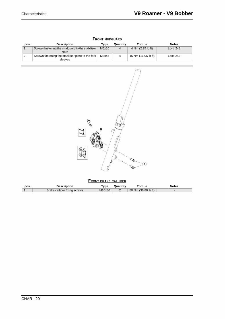
FRONT MUDGUARDpos. Description Type Quantity Torque Notes
1 Screws fastening the mudguard to the stabiliserplate
M5x10 4 4 Nm (2.95 lb ft) Loct. 243
2 Screws fastening the stabiliser plate to the forksleeves
M8x45 4 15 Nm (11.06 lb ft) Loct. 243
FRONT BRAKE CALLIPERpos. Description Type Quantity Torque Notes
1 Brake calliper fixing screws M10x30 2 50 Nm (36.88 lb ft) -
Characteristics V9 Roamer - V9 Bobber
CHAR - 20

FRONT WHEELpos. Description Type Quantity Torque Notes
1 Front wheel axle M18 1 80 Nm (59.00 lb ft) -2 Phonic wheel/brake disc fastening screws M8x18 6 25 Nm (18.44 lb ft) Loct. 243
Central part
V9 Roamer - V9 Bobber Characteristics
CHAR - 21

CHASSISpos. Description Type Quantity Torque Notes
1 Battery holder plate fastening screws M8x20 4 25 Nm (18.44 lb ft) -2 Front cradle SHC fixing screws M10x30 4 50 Nm (36.88 lb ft) -3 Pin fastening the stand to the cradles M10x266 1 50 Nm (36.88 lb ft) -
FOOTRESTSpos. Description Type Quantity Torque Notes
1 SHC screws fastening the rider foot-rest mounting
M8x45 4 25 Nm (18.44 lb ft) Loct. 243
2 Flanged hexagon screws fasteningthe footrest rubber guards
M6x12 8 10 Nm (7.38 lb ft) -
- Passenger footrest support fasteningscrews
M8x30 4 25 Nm (18.44 lb ft) -
Characteristics V9 Roamer - V9 Bobber
CHAR - 22

SIDE STANDpos. Description Type Quantity Torque Notes
1 Side stand retainer pin M10x1.25
1 10 Nm (7.38 lb ft) -
2 Lock nut for side stand bolt M10x1.25
1 30 Nm (22.13 lb ft) -
3 SHC screws fastening the switch M5x16 2 6 Nm (4.43 lb ft) Loct. 243
V9 Roamer - V9 Bobber Characteristics
CHAR - 23

FUEL TANKpos. Description Type Quantity Torque Notes
1 Tank rear fastening hexagon screw M8 1 25 Nm (18.44 lb ft) -2 Fuel pump fastening hexagon screws M5x16 6 5 Nm (3.69 lb ft) -3 SHC screws fastening the tank support buffers M8x16 2 25 Nm (18.44 lb ft) -
FILTER BOXpos. Description Type Quantity Torque Notes
1 Air filter box cover fastening self-threading screw
M5x14 4 3 Nm (2.21 lb ft) -
2 SWP screws fixing filter box to chas-sis
M5x20 2 3 Nm (2.21 lb ft) -
3 SWP filter box locking screws M5x20 9 3 Nm (2.21 lb ft) -
Characteristics V9 Roamer - V9 Bobber
CHAR - 24

CENTRAL BODYWORKPos. Description Type Quantity Torque Notes
1 TBEI screws fastening fearing M5x15 6 4 Nm (2.95 lb ft) -2 TE flanged screws fastening top
splash guardM6 2 10 Nm (7.38 lb ft) -
3 Flanged nuts fastening bottomsplash guard
M6 2 10 Nm (7.38 lb ft) -
V9 Roamer - V9 Bobber Characteristics
CHAR - 25

EXHAUST SYSTEMpos. Description Type Quantity Torque Notes
1 Lambda probes fastener M18x1.5 2 38 Nm (28.03 lb ft) -2 Flanged TBEI screws fixing exhausts
protectionsM6x10 6 8 Nm (5.90 lb ft) -
3 TBEI screws fixing mufflers to thesupports
M8x12 6 25 Nm (18.44 lb ft) -
4 Fixing exhaust pipes to the compen-sator
M8 1 25 Nm (18.44 lb ft) -
5 Fixing exhaust pipes to the mufflers M10 2 30 Nm (22.13 lb ft) -6 Flanged nuts fastening to the engine
exhaust pipesM8 4 25 Nm (18.44 lb ft) -
7 Nuts fastening mufflers' support tothe frame
M8x1.25 4 25 Nm (18.44 lb ft) -
ABS SYSTEMpos. Description Type Quantity Torque Notes
1 Control unit bracket fastening to theframe
M6x16 2 10 Nm (7.38 lb ft) -
2 Screws fastening the ABS modulatorto the support
M6x20 3 10 Nm (7.38 lb ft) -
3 SHC screw fastening the brake pipesfixing plate
M4x16 1 3 Nm (2.21 lb ft) -
4 SHC screw fastening the cablegrommet plate
M5x12 1 6 Nm (4.43 lb ft) -
Characteristics V9 Roamer - V9 Bobber
CHAR - 26
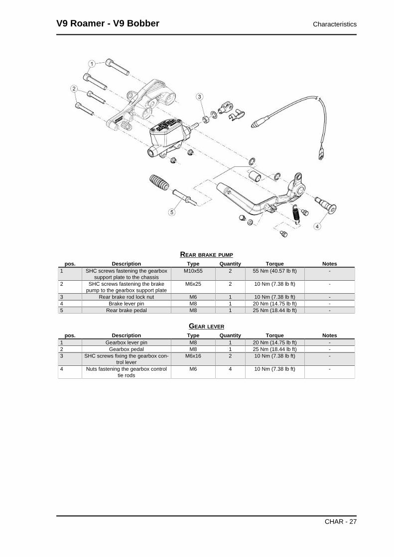
REAR BRAKE PUMPpos. Description Type Quantity Torque Notes
1 SHC screws fastening the gearboxsupport plate to the chassis
M10x55 2 55 Nm (40.57 lb ft) -
2 SHC screws fastening the brakepump to the gearbox support plate
M6x25 2 10 Nm (7.38 lb ft) -
3 Rear brake rod lock nut M6 1 10 Nm (7.38 lb ft) -4 Brake lever pin M8 1 20 Nm (14.75 lb ft) -5 Rear brake pedal M8 1 25 Nm (18.44 lb ft) -
GEAR LEVERpos. Description Type Quantity Torque Notes
1 Gearbox lever pin M8 1 20 Nm (14.75 lb ft) -2 Gearbox pedal M8 1 25 Nm (18.44 lb ft) -3 SHC screws fixing the gearbox con-
trol leverM6x16 2 10 Nm (7.38 lb ft) -
4 Nuts fastening the gearbox controltie rods
M6 4 10 Nm (7.38 lb ft) -
V9 Roamer - V9 Bobber Characteristics
CHAR - 27

GUARDSpos. Description Type Quantity Torque Notes
1 SWP screws fastening the framecover
- 4 3 Nm (2.21 lb ft) -
2 SHC screws fastening the head cov-er
M6x30 4 10 Nm (7.38 lb ft) -
3 Throttle body cover fastening screws M5x15 4 4 Nm (2.95 lb ft) -4 TBEI screws fastening the starter
motor coverM5x9 2 4 Nm (2.95 lb ft) -
Characteristics V9 Roamer - V9 Bobber
CHAR - 28

LOCKSpos. Description Type Quantity Torque Notes
1 Special screw fastening the ignitionlock
M8x15 1 At the point of failure -
2 Ignition lock fixing screw M8x15 1 25 Nm (18.44 lb ft) -3 Saddle release block fixing screws M8x25 2 10 Nm (7.38 lb ft) -
Back side
SWINGARMpos. Description Type Quantity Torque Notes
1 Pins fixing swingarm to gearbox - 2 - Manual2 Locknuts fixing swingarm to gearbox - 2 50 Nm (36.88 lb ft) -3 Torx screws fastening rubber bel-
lows- 3 6 Nm (4.43 lb ft) -
V9 Roamer - V9 Bobber Characteristics
CHAR - 29

REAR TRANSMISSIONpos. Description Type Quantity Torque Notes
1 Swingarm torx SHC fixing screws onthe transmission housing
M8x35 4 25 Nm (18.44 lb ft) -
REAR WHEELpos. Description Type Quantity Torque Notes
1 Rear wheel axle fixing nut M20 1 120 Nm (88.51 lb ft) -
Characteristics V9 Roamer - V9 Bobber
CHAR - 30

pos. Description Type Quantity Torque Notes2 Flanges TE screws fastening phonic
wheel and brake discM8x22 6 25 Nm (18.44 lb ft) Loct. 243
3 SHC screws fastening ABS sensorsupport
M6x12 2 10 Nm (7.38 lb ft) -
REAR BRAKE CALLIPERpos. Description Type Quantity Torque Notes
1 Flanged TE screws fixing rear brakecalliper
M8x30 2 25 Nm (18.44 lb ft) -
2 Rear brake calliper support pin M16 1 35 Nm (25.81 lb ft) -
V9 Roamer - V9 Bobber Characteristics
CHAR - 31

SHOCK ABSORBERSpos. Description Type Quantity Torque Notes
1 Top shock absorber SHC fixingscrews
M6x18 2 10 Nm (7.38 lb ft) -
2 Pin for fastening the shock absorberto chassis
M12 1 35 Nm (25.81 lb ft) Loct. 243
3 Pin for fastening the shock absorberto gearbox
M12 1 35 Nm (25.81 lb ft) Loct. 243
Characteristics V9 Roamer - V9 Bobber
CHAR - 32

REAR MUDGUARDpos. Description Type Quantity Torque Notes
1 Flanged screw fixing front mudguardto chassis
M6 2 10 Nm (7.38 lb ft) -
2 Mudguard side fixing screws to chas-sis
M8x20 4 35 Nm (25.81 lb ft) -
3 Big end rounded torx screw fasteningtop mudguard to chassis
M8x20 1 15 Nm (11.06 lb ft) -
4 SHC screws fastening the licenseplate and headlight support to the
mudguard
M6x30 2 10 Nm (7.37 lb ft) -
5 Flanged TBEI screws fixing licenceplate holder to frame
M6x16 1 10 Nm (7.37 lb ft) -
6 Licence plate cover self-threadingfixing screws
- 4 3 Nm (2.21 lb ft) -
7 Flanged TBEI screw fastening reflec-tor support
M5x16 1 6 Nm (4.43 lb ft) -
8 Flanged self-locking nut fastening re-flector
M5 1 6 Nm (4.43 lb ft) -
REAR LIGHTSpos. Description Type Quantity Torque Notes
1 SHC taillight fixing screws M6x20 1 10 Nm (7.38 lb ft) -2 TBEI screws fastening rear turn indi-
catorsM6x25 2 10 Nm (7.38 lb ft) -
V9 Roamer - V9 Bobber Characteristics
CHAR - 33

BEVEL GEARpos. Description Type Quantity Torque Notes
1 Pinion unit retainer nut M25x1.25 1 100 Nm (73.76 lb ft) Loct. 2432 Pinion unit retainer locknut M25x1.25 1 20 Nm (14.75 lb ft) Loct. 2433 Oil drainage plug M10x1.5 1 30 Nm (22.13 lb ft) -4 Oil load cap M12x1.5 1 25 Nm (18.44 lb ft) -5 Crown sprocket fixing ring nut - 1 100 Nm (73.76 lb ft) Loct. 2436 Crown fixing torx screws M8x25 8 25 Nm (18.44 lb ft) -
Recommended products chart
Piaggio & C. S.p.A. prescribes eni products for
the scheduled maintenance of its vehicles
RECOMMENDED PRODUCTS TABLEProduct Description Specifications
ENI i-RIDE PG 10W-60 Lubricant formulated with advanced syn-thetic technology and high performanceadditives to cater specifically for 4-strokeengines with high specific power outputs.
JASO MA, MA2 - API SG
AGIP GEAR MG SAE 85W-140 Transmission oil API GL-4 and GL-5ENI ROTRA LSX 75W-90 Gearbox oil API GL-5
AGIP FORK 7.5W Fork oil SAE 5W / SAE 20W
Characteristics V9 Roamer - V9 Bobber
CHAR - 34

Product Description SpecificationsAGIP GREASE SM 2 Gray black smooth-textured lithium
grease, containing molybdenum disul-phide.
-
Neutral grease or petroleum jelly. Battery polesAGIP BRAKE 4 Brake fluid SAE J 1703 -FMVSS 116 - DOT 3/4 - ISO
4925 - CUNA NC 956 DOT 4 syntheticfluid
NOTE
USE ONLY NEW BRAKE FLUID. DO NOT MIX DIFFERENT BRANDS OR TYPES OF OIL WITHOUTCHECKING THEIR BASE COMPATIBILITY.
V9 Roamer - V9 Bobber Characteristics
CHAR - 35

INDEX OF TOPICS
SPECIAL TOOLS S-TOOLS

SPECIAL TOOLSStores code Description
020998Y Pinion case key
020999Y Crown ring nut key
021000Y Bevel gear pair support
19.90.70.00 Extractor for internal ring on drilled bolt
021003Y Bevel gear oil seal punch
021005Y Punch seals on the bevel gear cover
V9 Roamer - V9 Bobber Special tools
S-TOOLS - 37

Stores code DescriptionGU19927900 Punch for pressing bearing inner ring on-
to drilled pin
GU19907000 Extractor for internal ring on drilled bolt
020360Y 52 x 55-mm Adaptor
020376Y Adaptor handle
001467Y036 Extract the inner bearing track
AP8140190 Tool for steering tightening
020922Y P.A.D.S.
Special tools V9 Roamer - V9 Bobber
S-TOOLS - 38

Stores code Description020931Y PADS instrument panel connection cable
V9 Roamer - V9 Bobber Special tools
S-TOOLS - 39

INDEX OF TOPICS
MAINTENANCE MAIN

Scheduled maintenance tableNOTE
CARRY OUT MAINTENANCE OPERATIONS AT HALF THE INTERVALS SPECIFIED IF THE VE-HICLE IS USED IN PARTICULAR RAINY OR DUSTY CONDITIONS, OFF ROAD OR FOR TRACKUSE.NOTE
THE TIMES LISTED ON THE SCHEDULED MAINTENANCE TABLE INCLUDE TIME DEDICATEDTO MANAGEMENT ACTIVITIES.
I: INSPECT AND CLEAN, ADJUST, LUBRICATE OR REPLACE IF NECESSARY
V: CHECK AND CLEAN, ADJUST AND REPLACE IF NECESSARY
C: CLEAN, R: REPLACE, A: ADJUST, L: LUBRICATE
(1) Replace in case of leaks.
(2) Replace every 2 years or 20,000 Km (12,427.42 mi).
(3) Replace every 4 years.
(4) At each engine start.
(5) Check every month.
(6) Check every 3000 km (1864.11 mi)
(7) Check and clean and adjust or replace, if necessary, every 1000 Km (621.37 mi)
(8) Replace at whichever of the following occurs first: 40000 km (24854.85 mi) or 4 years
ROUTINE MAINTENANCE TABLEkm x 1,000 (mi x 1,000) 1.5 (0.9) 10 (6.2) 20
(12.4)30
(18.6)40
(24.9)50
(31.1)60
(37.3)Spark plugs R R R R R RFilter box (9) C C C C C CTransmission cables and controls I I I I I I ISteering bearings and steering clearance I I I I I I IWheel bearings I I I I I IDiagnosis by tool I I I I I I IBrake discs I I I I I I IAir filter R R R R R ROil filter change C CEngine oil filter R R R R R R RLights operation / aiming I I I I I IVehicle general operation I I I I I I IRear wheel flexible coupling rubbers RBraking systems I I I I I I ILight circuit I I I I I I ISafety switches I I I I I I IBrake fluid (2) I I I I I I IGearbox oil R RFork oil (8) REngine oil (6) R R R R R R RFinal drive oil R RFork oil seal (1) I I I I I ITyres - pressure/wear (5) I I I I I I IValve clearance adjustment A A A A A A AWheels I I I I I I IBolts and nuts tightening I I I I I I IBattery terminals tightening ISuspension and setting I I I IEngine oil pressure warning light (4)Filter box drain plug C C C C C C C
V9 Roamer - V9 Bobber Maintenance
MAIN - 41

km x 1,000 (mi x 1,000) 1.5 (0.9) 10 (6.2) 20(12.4)
30(18.6)
40(24.9)
50(31.1)
60(37.3)
Fuel lines (3) I I I I I IBrake pipes I I I I I IClutch wear I I I I I IBrake pads wear (7) V V V V V V VLabour time (minutes) 110 90 100 90 130 90 110
NOTE
AT EACH SCHEDULED MAINTENANCE MUST BE VERIFIED WITH THE DIAGNOSTIC TOOL IFTHERE ARE ERRORS AND THE IF THE PARAMETERS ARE CORRECT.MAKE SURE THAT THE VEHICLE CALIBRATION IS UPDATED, AFTER PERFORMING THE UP-DATE OF THE DIAGNOSTIC TOOL.
Transmission fluid
Check
• Keep the vehicle upright with both wheels on the
ground.
• Unscrew and remove the cap/dipstick (1).
• The level is correct if the oil is close to the hole
of the cap/dipstick (1).
• If the oil is lower than specified, top-up until it
reaches the cap/dipstick hole (1).CAUTION
DO NOT ADD ADDITIVES OR OTHER SUBSTANCES TOTHE FLUID. WHEN USING A FUNNEL OR ANY OTHER EL-EMENT, MAKE SURE IT IS PERFECTLY CLEAN.
ReplacementCAUTION
THE UNIT MUST BE HOT WHEN THE OIL IS CHANGED AS UNDER SUCH CONDITIONS OIL ISFLUID AND THEREFORE EASY TO DRAIN.NOTE
RIDE SOME km (miles) TO WARM UP ENGINE OIL• Place a container with + 400 cm³ (25 cu in) capacity under the drainage plug (3).
• Unscrew and remove the drainage plug (3).
• Unscrew and remove the breather cap (2).
• Drain the oil into the container; allow several minutes for oil to drain out completely.
• Check and if necessary, replace the sealing washer of drainage plug (3).
• Remove any metal scrap attached to the drainage plug (3) magnet.
• Screw and tighten the drainage plug (3).
• Pour new oil through the fill opening (1) until it reaches the cap/dipstick hole (1).CAUTION
Maintenance V9 Roamer - V9 Bobber
MAIN - 42
DO NOT ADD ADDITIVES OR OTHER SUBSTANCES TO THE FLUID. WHEN USING A FUNNELOR ANY OTHER ELEMENT, MAKE SURE IT IS PERFECTLY CLEAN.
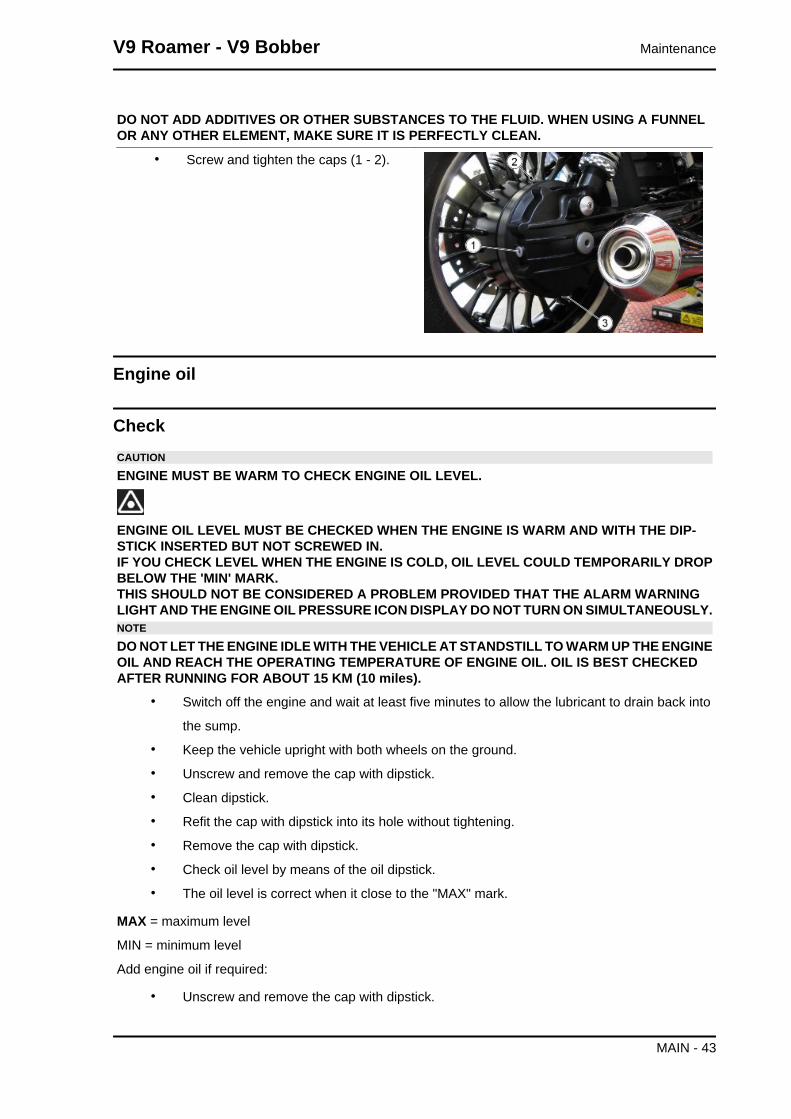
• Screw and tighten the caps (1 - 2).
Engine oil
CheckCAUTION
ENGINE MUST BE WARM TO CHECK ENGINE OIL LEVEL.
ENGINE OIL LEVEL MUST BE CHECKED WHEN THE ENGINE IS WARM AND WITH THE DIP-STICK INSERTED BUT NOT SCREWED IN.IF YOU CHECK LEVEL WHEN THE ENGINE IS COLD, OIL LEVEL COULD TEMPORARILY DROPBELOW THE 'MIN' MARK.THIS SHOULD NOT BE CONSIDERED A PROBLEM PROVIDED THAT THE ALARM WARNINGLIGHT AND THE ENGINE OIL PRESSURE ICON DISPLAY DO NOT TURN ON SIMULTANEOUSLY.NOTE
DO NOT LET THE ENGINE IDLE WITH THE VEHICLE AT STANDSTILL TO WARM UP THE ENGINEOIL AND REACH THE OPERATING TEMPERATURE OF ENGINE OIL. OIL IS BEST CHECKEDAFTER RUNNING FOR ABOUT 15 KM (10 miles).
• Switch off the engine and wait at least five minutes to allow the lubricant to drain back into
the sump.
• Keep the vehicle upright with both wheels on the ground.
• Unscrew and remove the cap with dipstick.
• Clean dipstick.
• Refit the cap with dipstick into its hole without tightening.
• Remove the cap with dipstick.
• Check oil level by means of the oil dipstick.
• The oil level is correct when it close to the "MAX" mark.
MAX = maximum level
MIN = minimum level
Add engine oil if required:
• Unscrew and remove the cap with dipstick.
V9 Roamer - V9 Bobber Maintenance
MAIN - 43
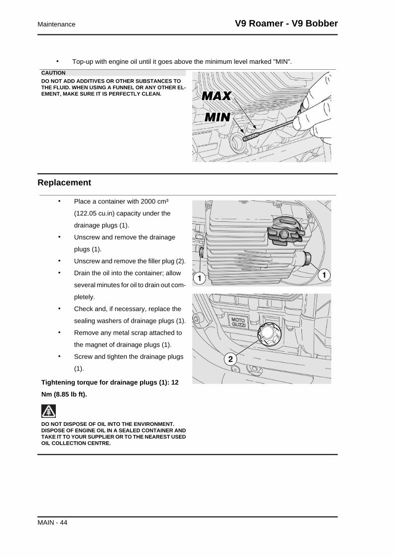
• Top-up with engine oil until it goes above the minimum level marked "MIN".CAUTIONDO NOT ADD ADDITIVES OR OTHER SUBSTANCES TOTHE FLUID. WHEN USING A FUNNEL OR ANY OTHER EL-EMENT, MAKE SURE IT IS PERFECTLY CLEAN.
Replacement
• Place a container with 2000 cm³
(122.05 cu.in) capacity under the
drainage plugs (1).
• Unscrew and remove the drainage
plugs (1).
• Unscrew and remove the filler plug (2).
• Drain the oil into the container; allow
several minutes for oil to drain out com-
pletely.
• Check and, if necessary, replace the
sealing washers of drainage plugs (1).
• Remove any metal scrap attached to
the magnet of drainage plugs (1).
• Screw and tighten the drainage plugs
(1).
Tightening torque for drainage plugs (1): 12
Nm (8.85 lb ft).
DO NOT DISPOSE OF OIL INTO THE ENVIRONMENT.DISPOSE OF ENGINE OIL IN A SEALED CONTAINER ANDTAKE IT TO YOUR SUPPLIER OR TO THE NEAREST USEDOIL COLLECTION CENTRE.
Maintenance V9 Roamer - V9 Bobber
MAIN - 44

Engine oil filter
• Undo the two screws (3) and remove
the cover (4).
• Remove the engine oil filter (5).NOTENEVER REUSE AN OLD FILTER.
• Spread a thin layer of oil on the sealing ring (6) of the new engine oil filter.
• Fit the new engine oil filter with the spring facing downwards.
• Refit the cover (4), screw and tighten the screw (3).
Gearbox Oil
COMPLETE GEAR - SELECTOR - DESMODROMICpos. Description Type Quantity Torque Notes
1 Gearbox fixing SHC screws M6x55 14 9-11 Nm (6.64-8.11 lbfft)
-
2 Oil load cap M20x1.5 1 23-27 Nm (16.96-19.91lb ft)
-
3 Oil filter cap M28x1 1 25-30 Nm (18.44-22.13lb ft)
-
4 Pre-selector pin M8 1 18-22 Nm (18.28-16.23lb ft)
Loct. DRI 2040
V9 Roamer - V9 Bobber Maintenance
MAIN - 45

pos. Description Type Quantity Torque Notes5 Washers fixing countersunk head
screwsM6x12 5 9-11 Nm (6.64-8.11 lbf
ft)Loct. DRI 2045
6 Plate fixing torx screw M5x16 1 6-7 Nm (4.42-5.16 lb ft) Loct. DRI 2045
ReplacementNOTE
HOT OIL IS MORE FLUID AND WILL DRAIN OUT MORE EASILY AND COMPLETELY.• Place a container with suitable capaci-
ty under the drainage plug (2).
• Unscrew and remove the drainage
plug (2).
• Unscrew and remove the filler plug (1).
• Drain the oil into the container; allow
several minutes for oil to drain out com-
pletely.
• Check and if necessary, replace the
sealing washers of drainage plug (2).
• Remove any metal scrap attached to
the drainage plug (2) magnet.
• Remove the air filter (3) and clean it
• Check the O-Ring (4) and if necessary
replace it
• Screw and tighten the drainage plug
(2)
• Pour in new oil, observing the quantity indicated in the table "capacity"
• Tighten the filler cap (1).CAUTION
DO NOT ADD ADDITIVES OR OTHER SUBSTANCES TO THE FLUID. WHEN USING A FUNNELOR ANY OTHER ELEMENT, MAKE SURE IT IS PERFECTLY CLEAN.
Maintenance V9 Roamer - V9 Bobber
MAIN - 46

Throttle body removal
• Remove the clip clamp fixing the
sleeve to the filter boxCAUTIONDURING REFITTING, REPLACE THE CLIP CLAMP
• Loosen the clamps that secure the sleeve to the intake manifolds
• Remove the sleeve
• Remove the battery
• Remove the MIU G3 control unit con-
nector support bracket fixing screw
V9 Roamer - V9 Bobber Maintenance
MAIN - 47

• Disconnect the MIU G3 control unit
connector
• Unscrew the clamp that secures the
throttle body to the filter box
• Extract the throttle body laterally
• Remove the throttle body guard
• Loosen the gas cables fixing nuts on
the throttle body and unhook them
Maintenance V9 Roamer - V9 Bobber
MAIN - 48

• Remove the throttle body
Braking system
V9 Roamer - V9 Bobber Maintenance
MAIN - 49

INDEX OF TOPICS
ELECTRICAL SYSTEM ELE SYS

Components arrangement
key:
1. Instrument panel
2. Coil
3. Fuel pump
V9 Roamer - V9 Bobber Electrical system
ELE SYS - 51

4. Injector
5. Taillight
6. MIU G3 Control Unit
7. Speed sensor
8. Starter motor
9. Engine speed sensor
10.Fuses
11.Battery
12.Head temperature sensor
13.Instrument panel air sensor
14.Headlamp
15.Voltage regulator
16.Alternator
17.Oil pressure sensor
18.Lambda probes
Electrical system installation
INTRODUCTION
Scope and applicability
The position of the wiring harnesses, how they are fixed to the motorcycle and potential problems are
defined on the following sections in order to reach the objectives of vehicle reliability.
Materials used and corresponding quantities
The electrical system consists of the following wiring harnesses and parts:
• 1 Vehicle wiring harness
• 1 Headlamp wiring harness
• 2 ABS speed sensor
• 1 Horn
• 2 Oxygen sensor
• 1 Stand switch
• 1 Fall sensor (grey connector)
Small parts and mountings
• 11 Large black 290x4 clamps
• 4 Small black 160x2.5 clamps
• 1 Small cable guide rubber clamp
• 2 Large cable guide rubber clamps
• 1 ECU bracket
• 2 Connector supports
Electrical system V9 Roamer - V9 Bobber
ELE SYS - 52

• 1 Cable grommet
• 1 Black sheath
• 7 ABS Cable grommets
• 1 connector clip
Motorcycle division
The wiring timing is subdivided in three essential
sections, as indicated in the figure.
1. Front section
2. Central section
3. Rear section
SPECIAL CHECKS FOR THE CORRECT CONNECTION AND LAYING OF CABLES
It is extremely important that any security-locks for the following connectors are properly con-
nected and correctly tightened to ensure proper engine, and therefore proper vehicle, operation.
Carry out the checks listed below.
• Instrument panel connector (is engaged and the boot well inserted)
• Rear and front wheel ABS sensor connector
• Check the correct routing of the rear turn indicators cables on the license plate holder (RH
and LH)
• Check the correct closing of the ABS ECU and the correct routing of the branch on the
conduit
• Taillight connector
• Right and Left light switch connectors
• Clutch connector
• Connector ignition switch connector (check that the cable is not live)
• Immobilizer antenna connector
• ECU connector (G3) and the correct insertion of the relative rubber plug
• Check the correct fastening of metallic bracket screw on the throttle body
• Check securing of the battery positive cable on the starter motor. Check if the cap is well
inserted
• Check the insertion of the starter motor faston
• Check the correct passage and fixing of the ABS fuse
• Check the right and left injectors connection
• Check the connection of the engine head temperature sensor
• Check the correct insertion of H.V. Cables with the Coils (RH and LH)
• Check whether the Grey H.V. Cable connects on the Coil with the Grey tape
V9 Roamer - V9 Bobber Electrical system
ELE SYS - 53

• Check whether the Grey H.V. Cable goes to the Left engine head
• Check the coils connection (and their correct positioning on the frame)
• Check the correct insertion of the engine oil cap
• Check ground fastening on the engine
• Check NEUTRAL cable fastening
• Check whether the right lambda probe is connected to the output labelled "LAMBDA DX" (RH
LAMBDA)
• Check the Regulator and Flywheel connection
• Check whether the right and left lambda probe cable is inserted on the cable grommet under
the clutch housing
• Check the right Lambda connections
• Check the Pick Up connection
• Check correct insertion of the starter motor hood and engine start Faston
• Check the presence of the Red protective hood on the battery Positive
• Check that the stand switch connector is blue and clamped
• Check the side stand connection and the left lambda
• Check the rear stop connection
• Check the stand switch cable ties on the frame under the vehicle
• Check the assembly of the fall sensor (if the arrow is upwards and the connector is grey)
• Check the connection of the secondary air valve and the correct positioning of the cap
• Check the connection of the front stop faston.CAUTION
THE ENCIRCLED CONNECTORS ARE CONSIDERED CRITICAL IN COMPARISON WITH ANYOTHER BECAUSE THE VEHICLE WILL STOP OR PRESENT A MALFUNCTION IF THEY ARE AC-CIDENTALLY DISCONNECTED.Undoubtedly the connection of the rest of connectors is also important and essential for thecorrect operation of the vehicle. It is also important and essential that the instructions regardingthe routing and fixing of the wiring harness in the various areas are followed meticulously inorder to guarantee functionality and reliability
COMPONENTS PRE-FITTING
TABLE A - ENGINE
• Check that the HV cable of the left cyl-
inder has grey taping
TABLE B - REAR COIL ON THE FRAME
Electrical system V9 Roamer - V9 Bobber
ELE SYS - 54

• Check that the coil in this position has the connector (wiring harness side) with two contacts
TABLE C - CONDUIT
• Check that the fall sensor arrow is up-
wards and that the connector is grey
• Place a large clamp so that the sensor
cable is positioned as indicated
• Check that the ABS control unit cable
is backwards, as illustrated in the im-
age
V9 Roamer - V9 Bobber Electrical system
ELE SYS - 55

Front side
TABLE A - FRONT WHEEL ABS SENSOR PAS-
SAGE
1. Front ABS sensor
2. Cable grommet
• Pass the front ABS sensor wiring har-
ness through the cable grommet as
indicated.
• Connect the front ABS sensor wiring harness with the brake pipe using cable guides (3)
Electrical system V9 Roamer - V9 Bobber
ELE SYS - 56

• Pass the ABS sensor wiring harness
around the steering column and
through the metallic cable grommet (4)
on the frame
TABLE B - STEERING LIGHTS CABLE PASSAGE ON THE HANDLE BAR
• Using the cable guides (1), fasten the RH light switch wiring harness with the throttle cable
• Using the cable guide (2), fasten the front stop switch wiring harness with the front brake
pipe
• Using the cable grommets (3), fasten the LH light switch wiring harness with the clutch cable
V9 Roamer - V9 Bobber Electrical system
ELE SYS - 57

TABLE B1
• Check that the front stop fastons are
well fastened, by slightly pulling them
TABLE C - PRE-FITTING OF THE EXTERNAL
AIR SENSOR ON THE INSTRUMENT PANEL
CAP
• Place the external air temperature sen-
sor in its seat on the instrument panel
cap
TABLE C1
• Fasten the external air temperature
sensor in its seat using an adhesive
sponge strip sized 40x20x3 mm
Electrical system V9 Roamer - V9 Bobber
ELE SYS - 58

TABLE D - INSTRUMENT PANEL FITTING
• Use a medium sized clamp to fasten
the instrument panel wiring harness
with the external air temperature sen-
sor, as illustrated
TABLE D1
• Check that the instrument panel con-
nector is well fastened and that the
protection case is well inserted
TABLE E - USB SOCKET
• Pass the USB socket wiring harness as
indicated
TABLE F - CABLE PASSAGE ON THE STEERING HEADSTOCK
• Pass it on the sides of the steering headstock and through the cable grommets on the frame
and under the side covers
V9 Roamer - V9 Bobber Electrical system
ELE SYS - 59

Central part
TABLE A - CONDUIT ON THE FRAME
• Check that the relays (1) are well in-
serted
• Fasten the rear part of the conduit us-
ing a large clamp (2)
Electrical system V9 Roamer - V9 Bobber
ELE SYS - 60

TABLE A1
• Pass the connector of the voltage reg-
ulator (1) and the horn connector (2) in
the hole created by the conduit with the
frame at the bottom, to facilitate their
connection
TABLE A2
• Main wiring harness (1)
TABLE A3
• Right light switch connector (1)
• Left light switch connectors (2)
• Coil connector 2 (3)
• Front ABS sensor connector (4)
• USB socket connector (5)
• Right turn indicator connector (6)
V9 Roamer - V9 Bobber Electrical system
ELE SYS - 61

TABLE A4
• Key connector (1)
• Immobilizer antenna connector (2)
• Right light switch connector (3)
• USB socket connector (4)
TABLE A5
• Left arrow connector (1)
• Left light switch connectors (2)
• Clutch switch connector (3)
• Fuel pump connector (4)
TABLE A6
• Pass t the PICK-UP connector (1) on
the right side of the frame
Electrical system V9 Roamer - V9 Bobber
ELE SYS - 62

TABLE A7
• Check that the connector of the coil (1)
is well coupled
TABLE A8
• Check that the connector of the engine
head temperature sensor (1) is well
coupled
• The HV cable (2) must remain inside
the conduit groove
TABLE B - COIL AND LEFT CYLINDER CON-
NECTION
• Check that the HV cable with grey mark
(left engine head) is well inserted in the
coil with grey mark on the connector
TABLE C - COIL AND RIGHT CYLINDER CON-
NECTION
• Check that the HV cable without grey
mark (right engine head) is well inser-
ted in the front coil
TABLE D - PROCEDURE FOR CORRECTLY FITTING THE ABS CONTROL UNIT CONNECTOR
• The initial position of the connector fastener lever must be as shown in the figure
V9 Roamer - V9 Bobber Electrical system
ELE SYS - 63

TABLE D1
• Place the connector on the opposite
side of the control unit and lower the
driving lever until the "click" that signals
the end of the stroke is heard.
TABLE D2
• When the connector is fully inserted,
the distance between the connector
and the ABS control unit must be 7.5
mm (0.29 in)
TABLE D3
• If the initial position of the connector
and driving lever is not as the one
shown in "TABLE D". The connector
will not be coupled correctly and the
measured distance will by greater, ap-
proximately 12 mm (0.47 in). In this
case, repeat the operations according
to the instructions in "TABLES D1/D2".
It is recommended to create a template
to check the correct insertion of the
connector.
Electrical system V9 Roamer - V9 Bobber
ELE SYS - 64

TABLE D4
• Check that the ABS control unit con-
nector cap is well inserted and that the
cable does not touch the frame
TABLE E - LAMBDA PROBES PASSAGE UN-
DER THE ENGINE
1. Right lambda probe wiring harness
2. Left lambda probe wiring harness
3. Cable grommet
4. Small clamp
TABLE E1
• Pass the wiring harness of the right
lambda probe (1) and of the left lambda
probe (2) under the starter motor, as
indicated
V9 Roamer - V9 Bobber Electrical system
ELE SYS - 65

TABLE F - PICK UP CABLE PASSAGE
• Pass the pick up cable between the
ABS modulator and the ABS connector
TABLE F1
• Pass the pick up cable through the cen-
tral flap, towards the right side of the
motorcycle
Electrical system V9 Roamer - V9 Bobber
ELE SYS - 66

TABLE F2
• Pass the pick up cable to the back of
the tank support and throttle cables
TABLE F3
• Check the correct connection of the
pick up connector
TABLE G - HORN AND REGULATOR
1. Voltage regulator
2. Horn
• The regulator's cable must pass be-
hind the frame bracket
V9 Roamer - V9 Bobber Electrical system
ELE SYS - 67

TABLE G1
• Check the connection of the flywheel
white connector and regulator's black
connector that must have a safety
clamp to avoid disconnection.
TABLE G2
• Using a medium clamp, fasten the reg-
ulator's cables along the frame's tube
Electrical system V9 Roamer - V9 Bobber
ELE SYS - 68

TABLE H - FLYWHEEL CABLES PASSAGE
• Using two medium clamps, fasten the
flywheel's wiring harness
TABLE I - NEUTRAL SENSOR CABLES PAS-
SAGE
• The wiring harness (1) of the neutral
sensor must pass through the filter box
support and in the cable guide (2)
V9 Roamer - V9 Bobber Electrical system
ELE SYS - 69
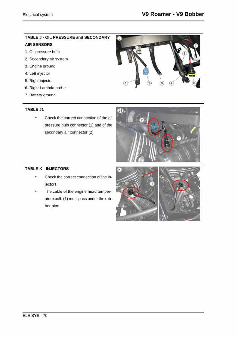
TABLE J - OIL PRESSURE and SECONDARY
AIR SENSORS
1. Oil pressure bulb
2. Secondary air system
3. Engine ground
4. Left injector
5. Right injector
6. Right Lambda probe
7. Battery ground
TABLE J1
• Check the correct connection of the oil
pressure bulb connector (1) and of the
secondary air connector (2)
TABLE K - INJECTORS
• Check the correct connection of the in-
jectors
• The cable of the engine head temper-
ature bulb (1) must pass under the rub-
ber pipe
Electrical system V9 Roamer - V9 Bobber
ELE SYS - 70

TABLE L - CONNECTION OF THE LEFT LAMB-
DA AND REAR ABS SENSOR
• Using a clamp, aligned with the frame
flap fixing the side fairing, fasten the
lambda probe wiring harness so that
the cables are covered
TABLE L1
• The wiring harnesses of the rear ABS
sensor, the connector of the side stand
and the faston for the starter motor
must pass through the cable grommet
(1)
THE CONNECTOR OF THE LEFT LAMBDA
PROBE AND THE ANTI-THEFT FITTING MUST
NOT PASS THROUGH THE CABLE GROMMET
• Check that the connector of the left
lambda probe (2) and the rear ABS
sensor (3) are correctly connected
V9 Roamer - V9 Bobber Electrical system
ELE SYS - 71

TABLE M - ANTI-THEFT FITTING POSITIONING
• The wiring harness of the anti-theft fit-
ting must pass under the frame, as
indicated
TABLE M1
• Using a small clamp, fasten the anti-
theft connector to one of the two gas
cables
TABLE N - RIGHT EXHAUST LAMBDA and
REAR BRAKE CONNECTION
1. Check that the neutral sensor connector is well
connected
2. Rear stop connector
3. Right Lambda probe connector
Electrical system V9 Roamer - V9 Bobber
ELE SYS - 72
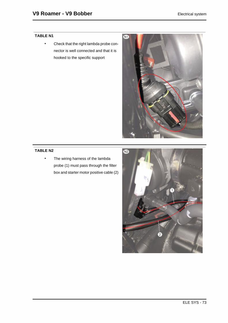
TABLE N1
• Check that the right lambda probe con-
nector is well connected and that it is
hooked to the specific support
TABLE N2
• The wiring harness of the lambda
probe (1) must pass through the filter
box and starter motor positive cable (2)
V9 Roamer - V9 Bobber Electrical system
ELE SYS - 73

TABLE O - REAR BRAKE WIRING HARNESS
PASSAGE
• Check that the rear brake sensor con-
nector is well connected
TABLE O1
• Pass the wiring harness of the rear
brake sensor (1) and of the rear BAS
sensor (2) through the cable grommet
(3) mounted on the engine and inside
the gearbox clutch lever.
TABLE O2
• Using a clamp, fasten the wiring har-
ness of the rear brake sensor (1) to the
wiring harness of the rear ABS sensor
(2)
• The rear ABS sensor wiring harness
must pass through the cable grommet
(3)
Electrical system V9 Roamer - V9 Bobber
ELE SYS - 74

TABLE O3
• The wiring harness of the rear ABS
sensor (2) must pass through the cable
grommet (3) located on the bracket (4)
that, in its turn, fixes the wiring harness
of the engine control unit (5) in line with
the rubber ring (6)
TABLE O4
• Fasten the wiring harness of the rear
brake sensor (1) using the cable grom-
mets (3)
TABLE P - ENGINE BATTERY GROUND
• An incorrect fastening of the fixing
screws of the engine battery ground
eyelet may cause the vehicle to catch
fire
• Check the tightening to the prescribed
torque
V9 Roamer - V9 Bobber Electrical system
ELE SYS - 75

TABLE Q - SIDE STAND SENSOR
• Using a small clamp, fasten the wiring
harness of the side stand switch, as in-
dicated
TABLE Q1
• Using a medium clamp, fasten the wir-
ing harness of the side stand switch to
the frame
TABLE Q2
• Pass the wiring harness of the side
stand switch under the starter motor
power supply cable
Electrical system V9 Roamer - V9 Bobber
ELE SYS - 76
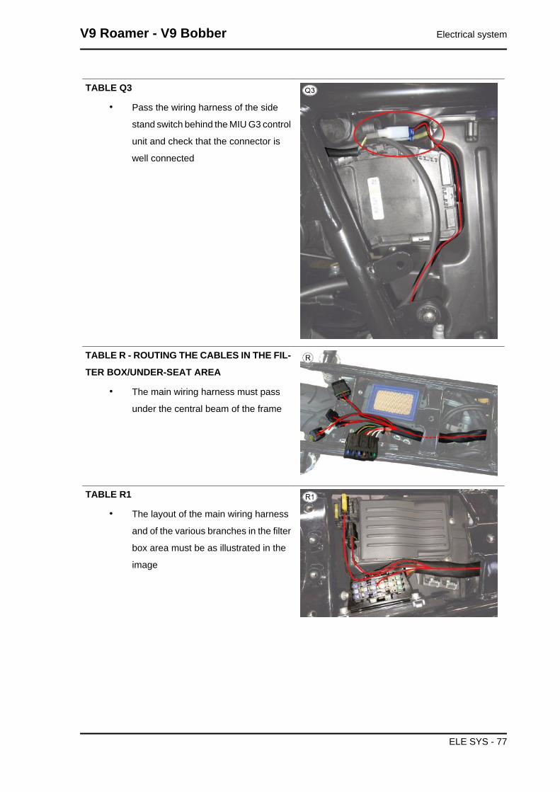
TABLE Q3
• Pass the wiring harness of the side
stand switch behind the MIU G3 control
unit and check that the connector is
well connected
TABLE R - ROUTING THE CABLES IN THE FIL-
TER BOX/UNDER-SEAT AREA
• The main wiring harness must pass
under the central beam of the frame
TABLE R1
• The layout of the main wiring harness
and of the various branches in the filter
box area must be as illustrated in the
image
V9 Roamer - V9 Bobber Electrical system
ELE SYS - 77

TABLE S - MAIN FUSES AND ABS
1. Fuse "A" (15A)
2. Fuse "B" (15A)
3. Fuse "C" (15A)
4. Fuse "D" (5A)
5. Fuse "E" (5A)
6. Fuse "F" (30A)
7. Fuse "G" (20A)
TABLE T - PASSAGE OF THE STARTER MO-
TOR BATTERY
• The cap of the battery positive (1) must
be red
• The cable that goes from the battery
positive to the fuse box must be cov-
ered with sheath (2) and the terminal
must be covered with heath shrink ma-
terial (3)
INCORRECT SECURING OF THIS COMPONENT MAYCAUSE THE VEHICLE TO CATCH FIRE
TABLE T1
• The motor starter cable must pass over
the filter box pipe
Electrical system V9 Roamer - V9 Bobber
ELE SYS - 78

TABLE T2
• Check that the starter positive cap is
correctly inserted and that the nut is
fastened to the prescribed toque
INCORRECT SECURING OF THIS COMPONENT MAYCAUSE THE VEHICLE TO CATCH FIRE
TABLE T3
• Check that the faston is correctly in-
serted
TABLE T4
• The protection cap may remain outside
for maximum 2-3 mm (0.078-0.118 in)
Back side
TABLE A - REAR WHEEL ABS SENSOR ROUTING
• Fasten the rear ABS sensor wiring harness to the brake pipe using one of the cable guides,
as indicated
V9 Roamer - V9 Bobber Electrical system
ELE SYS - 79

TABLE A1
• fasten the rear ABS sensor wiring har-
ness to the brake pipe, under the
swingarm, using one cable guide (1)
and a clamp (2)
TABLE A2
• Using a clamp, fasten all electric ca-
bles
TABLE B - REAR MUDGUARD PRE-FITTING
• Pre-fit the taillight wiring harness on
the mudguard and fasten it using the
specific flaps on the mudguard
TABLE C - TAILLIGHT CONNECTIONS
• In the marked areas there should be no
cables or connectors
Electrical system V9 Roamer - V9 Bobber
ELE SYS - 80

TABLE C1
• Using a medium clamp (1), fasten all
cables
• Pay attention so that the cables of the
turn indicators are inserted in the
space above the screws stern
TABLE C2
• Check the correct insertion of the rub-
ber ring on the license plate holder
TABLE D - TAILLIGHT CONNECTION AND
"MGPM" FITTING POSITIONING
• Check the correct connection of the
taillight connector
Checks and inspections
Dashboard
V9 Roamer - V9 Bobber Electrical system
ELE SYS - 81
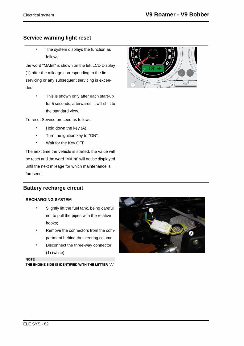
Service warning light reset
• The system displays the function as
follows:
the word "MAInt" is shown on the left LCD Display
(1) after the mileage corresponding to the first
servicing or any subsequent servicing is excee-
ded.
• This is shown only after each start-up
for 5 seconds; afterwards, it will shift to
the standard view.
To reset Service proceed as follows:
• Hold down the key (A).
• Turn the ignition key to "ON".
• Wait for the Key OFF.
The next time the vehicle is started, the value will
be reset and the word "MAInt" will not be displayed
until the next mileage for which maintenance is
foreseen.
Battery recharge circuit
RECHARGING SYSTEM
• Slightly lift the fuel tank, being careful
not to pull the pipes with the relative
hooks;
• Remove the connectors from the com-
partment behind the steering column
• Disconnect the three-way connector
(1) (white).NOTETHE ENGINE SIDE IS IDENTIFIED WITH THE LETTER "A"
Electrical system V9 Roamer - V9 Bobber
ELE SYS - 82
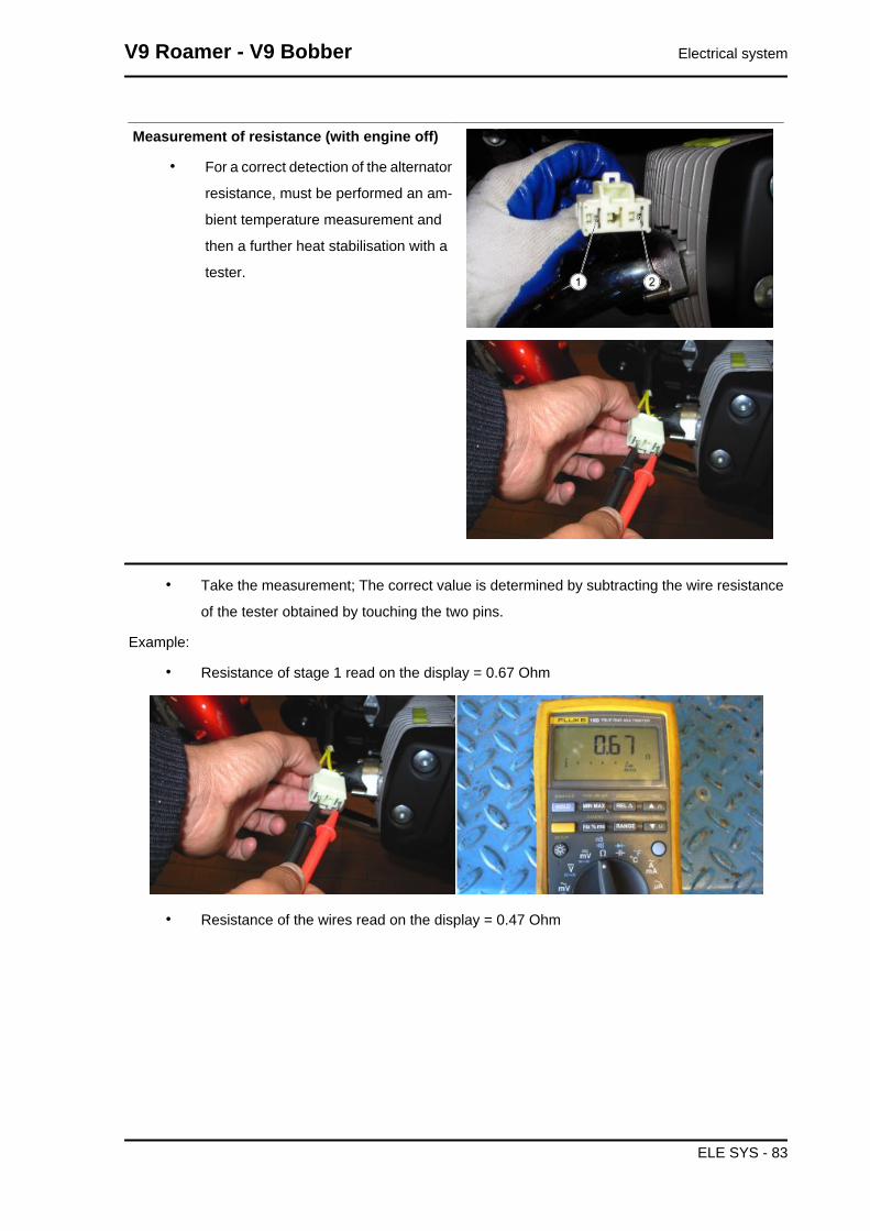
Measurement of resistance (with engine off)
• For a correct detection of the alternator
resistance, must be performed an am-
bient temperature measurement and
then a further heat stabilisation with a
tester.
• Take the measurement; The correct value is determined by subtracting the wire resistance
of the tester obtained by touching the two pins.
Example:
• Resistance of stage 1 read on the display = 0.67 Ohm
• Resistance of the wires read on the display = 0.47 Ohm
V9 Roamer - V9 Bobber Electrical system
ELE SYS - 83

• Effective resistance stage 1 = 0.67-0.47 = 0.20 Ohm
RESISTANCE MEASUREWinding stage Ambient temperature (ohm) Afterwards heat stabilisation (ohm)
Stage 1 0.18 - 0.23 0.20 - 0.25
Zero load voltage
• Disconnect the three-way connector (1);
• For a correct detection of the alternator voltage, a measurement must be carried out using
alternatively the 3 engine side connector pins: stage "1" (pin 1-2), stage "2" (pin 1-3), stage
"3" (pin 2-3)
• Take the measurements;
• If there is a significant difference between one stage and another (other than 15 V), this
means that the alternator is defective and must be replaced.CAUTION
WITH THE ENGINE HOT THE VALUES RECORDED ARE ON AVERAGE 4-5 V LESS THAN THOSEDETECTED WITH THE ENGINE COLD.
TENSIONE A VUOTOGiri / min 2000 4000 6000
Vm tensione concatenata Valori di riferimento ( Vrms )
40 - 45 82 - 87 132 - 138
Short-circuit current
• For a correct detection of the short-cir-
cuit current, a connector must be pre-
pared that generates a downstream
short circuit between the three alterna-
tor cables;
• Start the engine and with an ammeter
clamp measure each single cable.
Electrical system V9 Roamer - V9 Bobber
ELE SYS - 84

• If there is a significant difference be-
tween the measure of the single cables
(other than 10 A), this means that the
alternator is defective and must be re-
placed.CAUTIONWITH THE ENGINE HOT THE VALUES RECORDED AREON AVERAGE 2-3 A LESS THAN THOSE DETECTED WITHTHE ENGINE COLD.WARNINGNEVER KEEP THE ENGINE RUNNING FOR MORE THANONE MINUTE; FAILURE TO DO SO COULD CAUSE SERI-OUS OVERHEATING DAMAGES TO THE MOTORCYCLECIRCUITS.
COLD SHORT CIRCUIT CURRENTRPM 2000 4000 6000 8000
RMS DC current (Arms) (average of the 3 stagecurrents)
26 - 30 20 - 25 30 - 35 30 - 35
Voltage on battery poles with engine speed always between 3000 - 5000 RPM
• Start the engine, after about one minute of operating bring the speed to 3000-5000 RPM,
then measure with a tester the voltage at the battery poles that must always be between
13V and 15V. Otherwise, if the correct operation of the alternator has already been checked,
replace the regulator.CAUTION
PERFORM THE CHECK DESCRIBED ABOVE WITH A BATTERY IN GOOD CONDITION (STARTVOLTAGE ABOUT 13V) MAKING SURE THAT THERE ARE NO ELEMENTS IN THE SHORT CIR-CUIT.
Start-up system check
pick-up input about 100 A
V9 Roamer - V9 Bobber Electrical system
ELE SYS - 85
Fuses
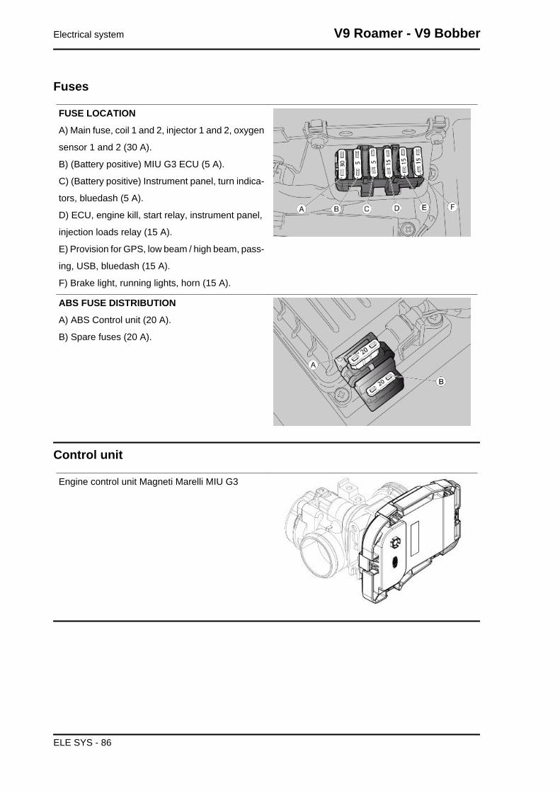
FUSE LOCATION
A) Main fuse, coil 1 and 2, injector 1 and 2, oxygen
sensor 1 and 2 (30 A).
B) (Battery positive) MIU G3 ECU (5 A).
C) (Battery positive) Instrument panel, turn indica-
tors, bluedash (5 A).
D) ECU, engine kill, start relay, instrument panel,
injection loads relay (15 A).
E) Provision for GPS, low beam / high beam, pass-
ing, USB, bluedash (15 A).
F) Brake light, running lights, horn (15 A).
ABS FUSE DISTRIBUTION
A) ABS Control unit (20 A).
B) Spare fuses (20 A).
Control unit
Engine control unit Magneti Marelli MIU G3
Electrical system V9 Roamer - V9 Bobber
ELE SYS - 86

Battery
CharacteristicBattery12 V - 12 Ah
Connectors
V9 Roamer - V9 Bobber Electrical system
ELE SYS - 87

INDEX OF TOPICS
ENGINE FROM VEHICLE ENG VE

CHASSISpos. Description Type Quantity Torque Notes
1 Battery holder plate fastening screws M8x20 4 25 Nm (18.44 lb ft) -2 Front cradle SHC fixing screws M10x30 4 50 Nm (36.88 lb ft) -3 Pin fastening the stand to the cradles M10x266 1 50 Nm (36.88 lb ft) -
Vehicle preparation
• To arrange for the removal of the engine block, you must first remove the saddle, fuel tank,
side fairings and the battery
• From the front, secure the vehicle with belts attached to a hoist
• Position a centre stand under the engine sump
• Position an engine support so as not to damage the rubber bellows of the drive shaft
V9 Roamer - V9 Bobber Engine from vehicle
ENG VE - 89

INDEX OF TOPICS
ENGINE ENG
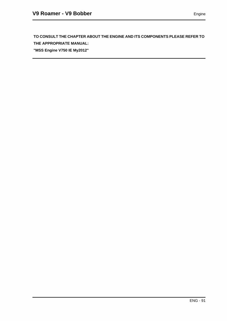
TO CONSULT THE CHAPTER ABOUT THE ENGINE AND ITS COMPONENTS PLEASE REFER TO
THE APPROPRIATE MANUAL:
"MSS Engine V750 IE My2012"
V9 Roamer - V9 Bobber Engine
ENG - 91

INDEX OF TOPICS
POWER SUPPLY P SUPP

Circuit diagram
key:
1. Fuel tank
2. Throttle body
3. Fuel filter
4. Fuel delivery pipe
5. Fuel pump unit
Injection
V9 Roamer - V9 Bobber Power supply
P SUPP - 93

Diagram
key:
1. Control unit position
2. Ignition switch
3. Battery
4. Fuel pump
5. Coils
6. Instrument panel
7. Air temperature sensor
8. Throttle valve position sensor
9. Injectors
10.Crankshaft position sensor
11.Engine temperature sensor
12.Lambda probe
Power supply V9 Roamer - V9 Bobber
P SUPP - 94

13.Side stand
ECU INFO screen page
This screen page shows general data regarding
the control unit, for example software type, map-
ping, control unit programming date
INFO ECU SCREEN PAGESpecification Desc./Quantity
Mapping -
PARAMETERS screen page
This screen page shows the parameters meas-
ured by the several sensors (engine revs, engine
temperature, etc.) or values set by the control unit
(injection time, ignition advance, etc.)
ENGINE PARAMETER READING SCREEN PAGENavigator characteristic P.A.D.S. characteristic Description / Value
Engine rpm Engine rpm Rpm: the minimum value is set by the control unit cannot beadjusted
Entire throttle position Throttle angle Rpm: the minimum value is set by the control unit cannot beadjusted
Engine temperature Engine temperature °C
V9 Roamer - V9 Bobber Power supply
P SUPP - 95

Navigator characteristic P.A.D.S. characteristic Description / ValueLeft lambda probe voltage Lambda probe voltage 1 100 - 900 mV (indicative values) Signal when energized that
the control unit receives from the lambda probe: inversely pro-portional to the presence of oxygen
Right lambda probe voltage Lambda probe voltage 2 100 - 900 mV (indicative values) Signal when energized thatthe control unit receives from the lambda probe: inversely pro-
portional to the presence of oxygenLeft cylinder lambda correc-tion
Lambda correction factor 1 -
Right cylinder lambda correc-tion
Lambda correction factor 2 -
Steps carried out Steps carried out Steps carried out of the control unit in minimum control phaseAdvance ignition carried out Advance carried out Value referring to left cylinderAdvance ignition programmed Advance programmed Value referring to left cylinderInjection time Injection time -Left cylinder adaptive correc-tion
Lambda adaptive gain 1 -
Right cylinder adaptive correc-tion
Lambda adaptive gain 2 -
Atmospheric pressure Atmospheric pressure The value is estimated by the control unitIntake pressure Intake pressure Pressure detected in the intake ductTarget idle rpm Idling target is a target value for the engine speed at the minimum set by
the control unit (with engine warm)Programmed steps Programmed steps Steps corresponding to the reference position of the engine idleIdle motor equivalent throttle Stepper equivalent throttle Expresses the minimum contribution of air in the motor throttle
degrees
ACTIVATION screen page
This screen page is used to delete errors in the
control unit memory and to activate some systems
controlled by the control unit.
DEVICES ACTIVATIONNavigator characteristic P.A.D.S. characteristic Description / Value
H.V. coil left cylinder Coil 1 -H.V. coil right cylinder Coil 2 -Rpm indicator Rpm indicator -Left injector Injector 1 -Right injector Injector 2 -
Power supply V9 Roamer - V9 Bobber
P SUPP - 96
Navigator characteristic P.A.D.S. characteristic Description / ValueIdle motor Stepper -Left lambda probe heater Lambda probe heater 1 -Right lambda probe heater Lambda probe heater 2 -Headlamp relay Headlamp relay -Fuel pump relay Fuel pump relay -Warning lamp control or EFIicon
General warning light -
Error clearing - -Reading errors of environmen-tal parameters
- -
Freezes and saves the param-eter values of the states
- -
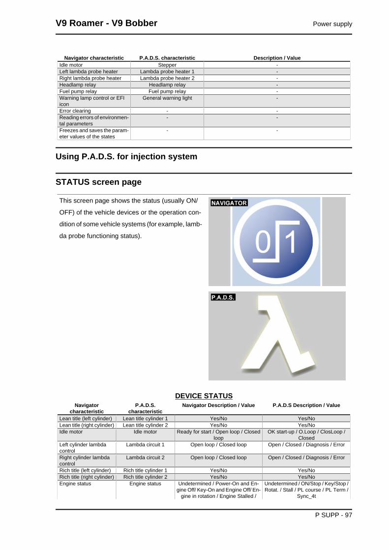
Using P.A.D.S. for injection system
STATUS screen page
This screen page shows the status (usually ON/
OFF) of the vehicle devices or the operation con-
dition of some vehicle systems (for example, lamb-
da probe functioning status).
DEVICE STATUSNavigator
characteristicP.A.D.S.
characteristicNavigator Description / Value P.A.D.S Description / Value
Lean title (left cylinder) Lean title cylinder 1 Yes/No Yes/NoLean title (right cylinder) Lean title cylinder 2 Yes/No Yes/NoIdle motor Idle motor Ready for start / Open loop / Closed
loopOK start-up / O.Loop / ClosLoop /
ClosedLeft cylinder lambdacontrol
Lambda circuit 1 Open loop / Closed loop Open / Closed / Diagnosis / Error
Right cylinder lambdacontrol
Lambda circuit 2 Open loop / Closed loop Open / Closed / Diagnosis / Error
Rich title (left cylinder) Rich title cylinder 1 Yes/No Yes/NoRich title (right cylinder) Rich title cylinder 2 Yes/No Yes/NoEngine status Engine status Undetermined / Power-On and En-
gine Off/ Key-On and Engine Off/ En-gine in rotation / Engine Stalled /
Undetermined / ON/Stop / Key/Stop /Rotat. / Stall / PL course / PL Term /
Sync_4t
V9 Roamer - V9 Bobber Power supply
P SUPP - 97
Navigatorcharacteristic
P.A.D.S.characteristic
Navigator Description / Value P.A.D.S Description / Value
Power-Latch in course / Power-Latchfinished / Engine in stop phase
Engine control - Synchronized on the 4 stroke cycle /Not synchronized on the 4 stroke cy-
cleThrottle Throttle status Minimum opening / Partial opening /
Maximum openingMinimum / Partial / FullPot
Start request Start request Yes/No Absent/presentRpm sensor signalspanel
Synchronised panel Not synchronized / synchronized /Partially synchronized
Partial / NO / YES / Lean / Rich / Richtitle/ Error / Lean title
Engine stop button RUN / OFF switch Gear enabled / Gear not enabled RUN / OFFSide stand - Up/DownLeft lambda probe shortterm diagnosis
- Complete / Not complete
Right lambda probeshort term diagnosis
- Complete / Not complete
Left lambda probe shortterm error
- Yes / No / Not detectable
Right lambda probeshort term error
- Yes / No / Not detectable
Minimum motor shortterm diagnosis
motor.diag min.comp Complete / Not complete Complete / Not done
Minimum motor shortterm error
Idle motor error Yes / No / Not detectable Yes/No
Fan relay Fan relay Not activated / Activated OFF / 2 active / 1 active / req. 1 / req.2
Engine mode Engine mode Undetermined/ Start-up / Start-upstabilized / Start-up with decelera-tion / Start-up with acceleration /
Idling compensated for start-up / En-gine stable outside idling / Engine
idling
Undeterm / Start / Stabil / Start_dec /Start_acc / Min_Comp / Stable / Min /Accel. / Decel. / Cut-Off / RCUT-OFF
Engine mode Engine mode Engine in acceleration / Engine in de-celeration / Cut-Off /
Gearbox in neutral Gear engaged Yes/No Yes/NoClutch Clutch Released / Pulled Released / PressedLeft lambda probe - Operative / Not operative (Error) /
Not operative (Rich) / Not operative(Lean) / Not operative (Heater) / Not
operative (Start-up) / Not enabledRight Lambda probe - Operative / Not operative (Error) /
Not operative (Rich) / Not operative(Lean) / Not operative (Heater) / Not
operative (Start-up) / Not enabledRiding Enable Start-up enabling
switchYes/No
- Stepper motor status - OK start-up / O.Loop / ClosLoop- Fall sensor - Inhibited / Consent / --- / Crack De-
cel. / Crank Accel. / Crank Minimum /Stabilized / Minimum / Accelerated /
Decelerated / CAT-OFF status /CAT-OFF Output
- Recharge status Ena-bling Ignition
- OFF / ON / Kick Down / Close Loop /Diag ShortTerm / Error ShortTerm
Power supply V9 Roamer - V9 Bobber
P SUPP - 98

ERRORS screen page
This screen page displays any errors detected in
the vehicle (ATT) or stored in the control unit
(MEM) and you can check that the cancellation of
error (STO) has taken place.
ERRORS DISPLAYError
Navigatorcharacteristic
P.A.D.S.characteristic
Navigator Description / Value P.A.D.S Description / Value
P0105
Air pressure sen-sor
Ambient pres-sure sensor
short circuit to positive / open or shortcircuit to negative / signal not plausible
Short circuit to positive / Open or shortcircuit to ground / Signal not plausible
P0110
Air temperaturesensor
Air temperaturesensor
short circuit or open circuit to positive /short circuit to negative
Open or short circuit to positive / Shortcircuit to ground
P0115
Engine tempera-ture sensor
Engine tempera-ture sensor
short circuit or open circuit to positive /short circuit to negative
Open or short circuit to positive / Shortcircuit to ground
P0120
TPS Throttle positionsensor (TPS)
short circuit or open circuit to positive /short circuit to negative
Open or short circuit to positive / Shortcircuit to ground
P0130
Control of air-fuelratio / Left lamb-
da probe
Lambda probesignal (Bank 1)
short circuit to positive / open circuit,short circuit to negative or excessively
lean carburation / signal not plausible fortitle correction
Short circuit to positive / Open or shortcircuit to ground / Signal not plausible
P0135
Left lambdaprobe heater
Lambda heatercirc. (Bank 1)
short circuit to positive/ short circuit tonegative / open circuit
Short circuit to positive / Short circuit toground / Open circuit
P0136
Control of air-fuelratio / Right lamb-
da probe
Lambda probesignal (Bank 2)
short circuit to positive / open circuit,short circuit to negative or excessively
lean carburation / signal not plausible fortitle correction
Short circuit to positive / Open or shortcircuit to ground / Signal not plausible
P0141
Right lambdaprobe heater
Lambda heatercirc. (Bank 2)
short circuit to positive/ short circuit tonegative / open circuit
Short circuit to positive / Short circuit toground / Open circuit
P0169
Starter button Starter signal shorted to positive Short circuit to positive
P0170
Starter Starter diagnosis(relay)
TBD Short circuit to positive / Open circuit toground
V9 Roamer - V9 Bobber Power supply
P SUPP - 99

Error
Navigatorcharacteristic
P.A.D.S.characteristic
Navigator Description / Value P.A.D.S Description / Value
P0201
Left cylinder in-jector
Injector circuitcylinder 1
short circuit to positive/ short circuit tonegative / open circuit
Short circuit to positive / Short circuit toground / Open circuit
P0202
Right cylinder in-jector
Injector circuitcylinder 2
short circuit to positive/ short circuit tonegative / open circuit
Short circuit to positive / Short circuit toground / Open circuit
P0230
Fuel pump relay Fuel pump relaycontrol circuit
short circuit to positive/ short circuit tonegative / open circuit
Short circuit to positive / Short circuit toground / Open circuit
P0335
Engine speedsensor (electric)
Engine speedsensor
open circuit Open Circuit
P0336
Engine speedsensor (function-
al)
Engine speedsensor (Plausibil-
ity)
signal not valid Signal not valid
P0351
H.V. coil No. 1 coil circuit short circuit to positive / short circuit oropen circuit to negative
Short circuit to positive / Short circuit oropen circuit to ground
P0352
H.V. coil No. 2 coil circuit short circuit to positive / short circuit oropen circuit to negative
Short circuit to positive / Short circuit oropen circuit to ground
P0505
Idle control Idle control(Stepper motor)
short circuit to positive/ short circuit tonegative / open circuit / overpressure
Short circuit to positive / Short circuit toground / Open circuit / Overpressure
above specificationsP0530
Light relay Headlamp relaycommand
short circuit to positive/ short circuit tonegative / open circuit
Short circuit to positive / Short circuit toground / Open circuit
P0560
Battery voltage Battery voltage above maximum threshold / below mini-mum threshold
Voltage exceeds maximum limit
P0601
Control unit EEPROM Error(emul. Flash)
EEPROM error Internal failure to ECU
P0604
Control unit RAM error RAM error Internal failure to ECU
P0605
Control unit ROM error(Flash)
ROM error (Flash) Internal failure to ECU
P0606
Control unit Microprocessorerror
Microprocessor error Internal failure to ECU
P0650
Warning lamp Warning LampCommand
short circuit to positive/ short circuit tonegative / open circuit
Short circuit to positive / Short circuit toground / Open circuit
SETTINGS screen page
This screen page is used to adjust some control
unit parameters.
Power supply V9 Roamer - V9 Bobber
P SUPP - 100

ADJUSTABLE PARAMETERSNavigator characteristic P.A.D.S. characteristic Description / Value
Throttle position self-acquisi-tion
TPS reset -
Saved data file download Mem. data download (Down-load + Clearing)
-
Clearing memorized data Mem. data download (Down-load + Clearing)
-
Self-adjustable parameters re-set
Self-adjustable parameters re-set
-
V9 Roamer - V9 Bobber Power supply
P SUPP - 101

INDEX OF TOPICS
SUSPENSIONS SUSP

Front
FRONT WHEELpos. Description Type Quantity Torque Notes
1 Front wheel axle M18x1.5 1 80 Nm (59.00 lb ft) -2 Front brake disc fixing screw M8x20 6 25 Nm (18.44 lb ft) Loctite 243
Handlebar
(V7 SPECIAL / V7 STONE)
V9 Roamer - V9 Bobber Suspensions
SUSP - 103

HANDLEBAR AND CONTROLSPos. Description Type Quantity Torque Notes1 Switch fastener screw SWP 5 1+1 1.5 Nm (1.11 lb ft) -2 Counterweight fixing screw M6 2 10 Nm (7.38 lb ft) Loctite 2433 Screw fastening the clutch control U-bolt to
the semi-handlebarM6x25 2 10 Nm (7.37 lb ft) -
(V7 RACER)
Suspensions V9 Roamer - V9 Bobber
SUSP - 104

HANDLEBAR AND CONTROLSPos. Description Type Quantity Torque Notes1 Switch fastener screw M5 1+1 1.5 Nm (1.11 lb ft) Tighten using a 1-2-1 se-
quence2 Semi-handlebar fixing screw M6x25 4 10 Nm (7.37 lb ft) Tighten using a 1-2-1 se-
quence3 Counterweight fixing screw M6 2 10 Nm (7.37 lb ft) Loctite 2434 Screw fastening the clutch control U-bolt to
the semi-handlebarM6x25 2 10 Nm (7.37 lb ft) Tighten using a 1-2-1 se-
quence
V9 Roamer - V9 Bobber Suspensions
SUSP - 105

Front fork
FRONT SUSPENSION - STEERINGpos. Description Type Quantity Torque Notes
1 Stanchion cap - 2 50 Nm (36.88 lb ft) -2 Screw fixing wheel axle to right fork leg M6x30 2 10 Nm (7.37 lbf ft) Tighten using a 1-2-1 se-
quence3 Screw fixing stanchions to upper and lower
plateM10x40 4 50 Nm (36.88 lbf ft) -
4 Headstock ring nut M25x1 1 7 Nm (5.16 lbf ft) The fork must fall to oneside by itself
Suspensions V9 Roamer - V9 Bobber
SUSP - 106

pos. Description Type Quantity Torque Notes5 Headstock bushing M23x1 1 50 Nm (36.88 lbf ft) -
Diagram
Key:
1. Screw
2. Washer
3. Screw
4. Complete left sleeve
5. Upper bushing
6. Washer
7. Sealing ring
8. Snap ring
9. Dust guard
10.Stem
11.Lower bushing
12.Buffer
13.Counter spring
14.Complete pumping member
15.Spring
16.Pipe
17.Complete cap
V9 Roamer - V9 Bobber Suspensions
SUSP - 107
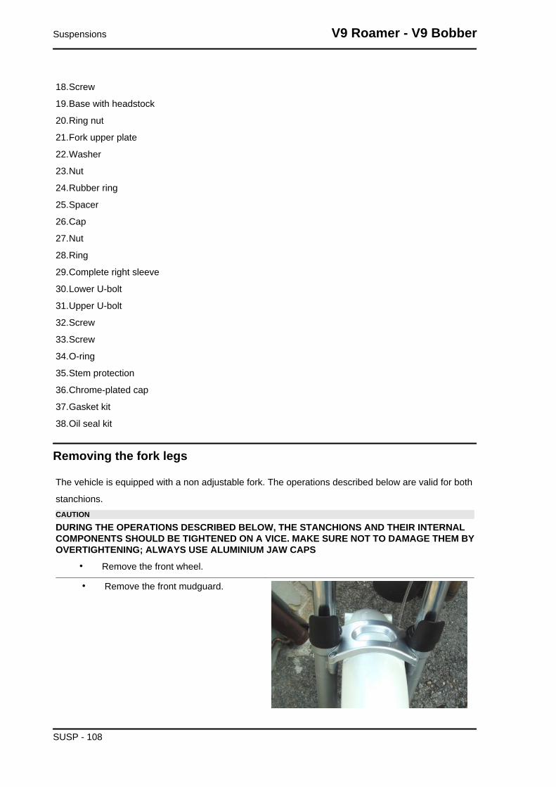
18.Screw
19.Base with headstock
20.Ring nut
21.Fork upper plate
22.Washer
23.Nut
24.Rubber ring
25.Spacer
26.Cap
27.Nut
28.Ring
29.Complete right sleeve
30.Lower U-bolt
31.Upper U-bolt
32.Screw
33.Screw
34.O-ring
35.Stem protection
36.Chrome-plated cap
37.Gasket kit
38.Oil seal kit
Removing the fork legs
The vehicle is equipped with a non adjustable fork. The operations described below are valid for both
stanchions.CAUTION
DURING THE OPERATIONS DESCRIBED BELOW, THE STANCHIONS AND THEIR INTERNALCOMPONENTS SHOULD BE TIGHTENED ON A VICE. MAKE SURE NOT TO DAMAGE THEM BYOVERTIGHTENING; ALWAYS USE ALUMINIUM JAW CAPS
• Remove the front wheel.
• Remove the front mudguard.
Suspensions V9 Roamer - V9 Bobber
SUSP - 108

• Undo and remove the two screws and
collect the washers.
• Move the instrument panel forwards.
• Undo the upper sealing screw.
• Undo the lower sealing screw.
• Slide off the stem downwards by turning it slightly first in one direction then to the opposite
direction.
Draining oil
To drain out the oil follow these steps.
• Remove the stanchion.
V9 Roamer - V9 Bobber Suspensions
SUSP - 109

• Tighten the removed stanchion in a
vice fitted with aluminium jaw caps in
order to avoid damaging them.
• Unscrew the upper closing cap. Pay
attention to the possible thrust that the
spring can cause to the loosened cap.
• Be careful not to damage the O-Ring
during extraction.
• Press the bearing tube inside the
wheel holder fork leg.
• Remove the preload tube and the
spring.
Suspensions V9 Roamer - V9 Bobber
SUSP - 110

• Drain out all the oil inside the stan-
chion.NOTEFOR EASY DRAINAGE OF THE OIL INSIDE THE PISTONROD, PRESS THE STANCHION IN THE WHEEL HOLDERSLEEVE TO PUMP OIL OUT.
• Carefully check each part of the stan-
chion and make sure that there are no
damaged elements.
• If there are no damaged or worn ele-
ments, refit the stanchion; otherwise,
replace the damaged elements.NOTEFOR EASY DRAINAGE OF THE OIL INSIDE THE PISTONROD, PRESS THE STANCHION IN THE WHEEL HOLDERSLEEVE TO PUMP OIL OUT.
Disassembling the fork
• Drain all the oil from the stem.
• Block the wheel holder fork leg on the
vice.
• Undo the bottom screw and remove it
with the corresponding gasket.
• Remove the dust scraper using a
screwdriver as a lever.CAUTIONBE CAREFUL NOT TO DAMAGE THE FORK LEG RIM ANDTHE DUST SCRAPER.
V9 Roamer - V9 Bobber Suspensions
SUSP - 111

• Slide the dust scraper off and upwards.
• Remove the locking ring inside the fork
leg using a thin screwdriver.CAUTIONBE CAREFUL NOT TO DAMAGE THE FORK LEG RIM.
• Slide off the bearing tube from the
wheel holder fork leg together with the
sealing ring, the cap, the upper bush-
ing and lower bushings.NOTEWHEN REMOVING THE PIPE FROM THE WHEEL HOLDERFORK LEG SOME PARTS MAY REMAIN INSIDE THE FORKLEG. IF THIS OCCURS, THESE PARTS MUST BE RE-MOVED AFTERWARDS, BEING CAREFUL NOT TO DAM-AGE THE FORK LEG RIM AND THE UPPER BUSHINGSEAT
Checking the components
• Check every component removed from
the fork leg, specially: the sealing ring
and the dust guard as they are ele-
ments that guarantee sealing; replace
them if some of them are damaged.
• Check the bushing on the bearing tube;
remove it and replace it if damaged or
worn.
• Slide off the pumping member unit
from the holding tube; if it is damaged,
replace the counter spring and the ring.
Suspensions V9 Roamer - V9 Bobber
SUSP - 112
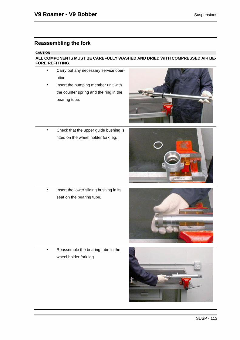
Reassembling the forkCAUTION
ALL COMPONENTS MUST BE CAREFULLY WASHED AND DRIED WITH COMPRESSED AIR BE-FORE REFITTING.
• Carry out any necessary service oper-
ation.
• Insert the pumping member unit with
the counter spring and the ring in the
bearing tube.
• Check that the upper guide bushing is
fitted on the wheel holder fork leg.
• Insert the lower sliding bushing in its
seat on the bearing tube.
• Reassemble the bearing tube in the
wheel holder fork leg.
V9 Roamer - V9 Bobber Suspensions
SUSP - 113

• Insert the bearing tube in the wheel
holder and push it until it stops.
• Screw the bottom screw and tighten it
to the prescribed torque.
• Insert the cap and the well-lubricated
sealing ring on the bearing tube.
• Use a suitable inserting tool to push the
sealing ring in the fork leg until it stops.
• Fit the locking ring.
Suspensions V9 Roamer - V9 Bobber
SUSP - 114

• Fit the dust scraper.
• Pour oil into the bearing tube so that it
also fills the internal grooves of the
pumping member rod.
• Pump with the bearing tube, making
sure the oil has completely filled the
pumping member rod.
• Introduce the spring and the preload
tube.
• Place the cap on the bearing tube, tak-
ing care not to damage the O-ring.
Then, tighten the cap to the prescribed
torque.
Filling oil
• Place the sleeve upright in a vice fitted
with protection jaws.
• Compress the sleeve in the stanchion.
• Pour part of the fork oil into the sleeve.
• Wait some minutes until the oil fills all
the ducts.
• Pour the remaining oil.
• Pump out oil a few times.
• Measure the air gap between the oil
level and the rim.
THE SLEEVE MUST BE PERFECTLY UPRIGHT IN ORDERTO MEASURE THE CORRECT OIL LEVEL. THE OIL LEVELMUST BE THE SAME IN BOTH STANCHIONS.
CharacteristicOil level (from sleeve rim, without the springand with stem at end of stroke)120 +/- 1.5 mm (4.72 +/- 0.06 in)
V9 Roamer - V9 Bobber Suspensions
SUSP - 115

• Introduce the spring and the preload
tube.
• Place the cap on the bearing tube, tak-
ing care not to damage the O-ring.
• Then, tighten the cap to the prescribed
torque.
Installing the fork legs
• Insert the stem on the vehicle going through the lower plate and the upper plate.
• Tighten the screws to the prescribed torque.
Suspensions V9 Roamer - V9 Bobber
SUSP - 116
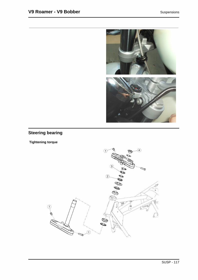
Steering bearing
Tightening torque
V9 Roamer - V9 Bobber Suspensions
SUSP - 117

STEERINGpos. Description Type Quantity Torque Notes
1 Screw fixing stanchions to upper and lowerplate
M10x40 4 25 Nm (18.44 lb ft) -
2 Steering headstock ring nut (pre-tightening) - 1 60 Nm (44.25 lb ft) -2 Steering headstock ring nut (tightening) - 1 50 +/- 5 Nm (36.88
+/- 3.69 lb ft)-
3 Headstock counter ring nut - 1 - Screw until obtainingcontact with the rubber
washer4 Headstock bushing - 1 100 Nm (73.76 lb ft) -
Rear
Shock absorbers
(V7 SPECIAL / V7 STONE)
(V7 RACER)
Suspensions V9 Roamer - V9 Bobber
SUSP - 118

REAR SUSPENSIONpos. Description Type Quantity Torque Notes
1 Upper screw fastening shock absorber toframe
M6x35 2 10 Nm (7.38 lb ft) Loctite 243
2 Lower pin fastening left shock absorber toswingarm
M10x1.5 1 35 Nm (25.81 lb ft)
3 Stud bolt fixing right shock absorber to rearbox
M12x1.5 1 35 Nm (25.81 lb ft) -
4 Screw fastening right shock absorber to studbolt
M6x16 1 10 Nm (7.37 lbf ft) Loctite 243
Removing
• Remove the screw fixing the right-hand
rear right shock absorber and pull it
from the pin on the drive shaft
V9 Roamer - V9 Bobber Suspensions
SUSP - 119

• Remove the screw and the relative nut
fixing the left rear shock absorber
• Unscrew and remove the upper
screws;
• Remove the shock absorbers.
Suspensions V9 Roamer - V9 Bobber
SUSP - 120

INDEX OF TOPICS
CHASSIS CHAS

Wheels
Front wheel
FRONT WHEELpos. Description Type Quantity Torque Notes
1 Front wheel axle M18 1 80 Nm (59.00 lb ft) -2 Phonic wheel/brake disc fastening screws M8x18 6 25 Nm (18.44 lb ft) Loct. 243
Removal
• Place the vehicle on a stable support
so that the front wheel does not touch
the ground;
• Remove the brake calliper without dis-
connecting the oil pipes;
• Working on the right side of the motor-
cycle, remove the cap from the pin;
Chassis V9 Roamer - V9 Bobber
CHAS - 122

• Loosen the two wheel pin locking
screws;
• Unscrew and remove the wheel pin;
• Working on the opposite side, remove
the left spacer;NOTEDURING REFITTING, PAY ATTENTION TO THE CORRECTPOSITIONING OF THE SPACER WHICH MUST BE INSER-TED IN THE DUST SEAL UNTIL IT REACHES THE BEAR-ING
• Working on the opposite side, remove
the left spacer;NOTEDURING REFITTING, PAY ATTENTION TO THE CORRECTPOSITIONING OF THE SPACER WHICH MUST BE INSER-TED IN THE DUST SEAL UNTIL IT REACHES THE BEAR-ING
V9 Roamer - V9 Bobber Chassis
CHAS - 123

• Remove the dust seal from both sides
• Using a generic bearing extractor remove the bearings from both sides
Rear wheel
REAR WHEELpos. Description Type Quantity Torque Notes
1 Rear wheel axle fixing nut M20 1 120 Nm (88.51 lb ft) -2 Flanges TE screws fastening phonic
wheel and brake discM8x22 6 25 Nm (18.44 lb ft) Loct. 243
3 SHC screws fastening ABS sensorsupport
M6x12 2 10 Nm (7.38 lb ft) -
Chassis V9 Roamer - V9 Bobber
CHAS - 124

Rimozione
• Remove the screw fixing the right-hand
rear right shock absorber and pull it
from the pin on the drive shaft
• Remove the screw fixing the left-hand
rear shock absorber and remove it
from the pin
• Using a jack, lift the rear of the motor-
cycle.
• Unscrew the rear fixing screw of the
rear brake calliper support
• Unscrew the wheel axle nut, making
sure to take the washer from the left
side and pull the pin itself from the right
side.
V9 Roamer - V9 Bobber Chassis
CHAS - 125
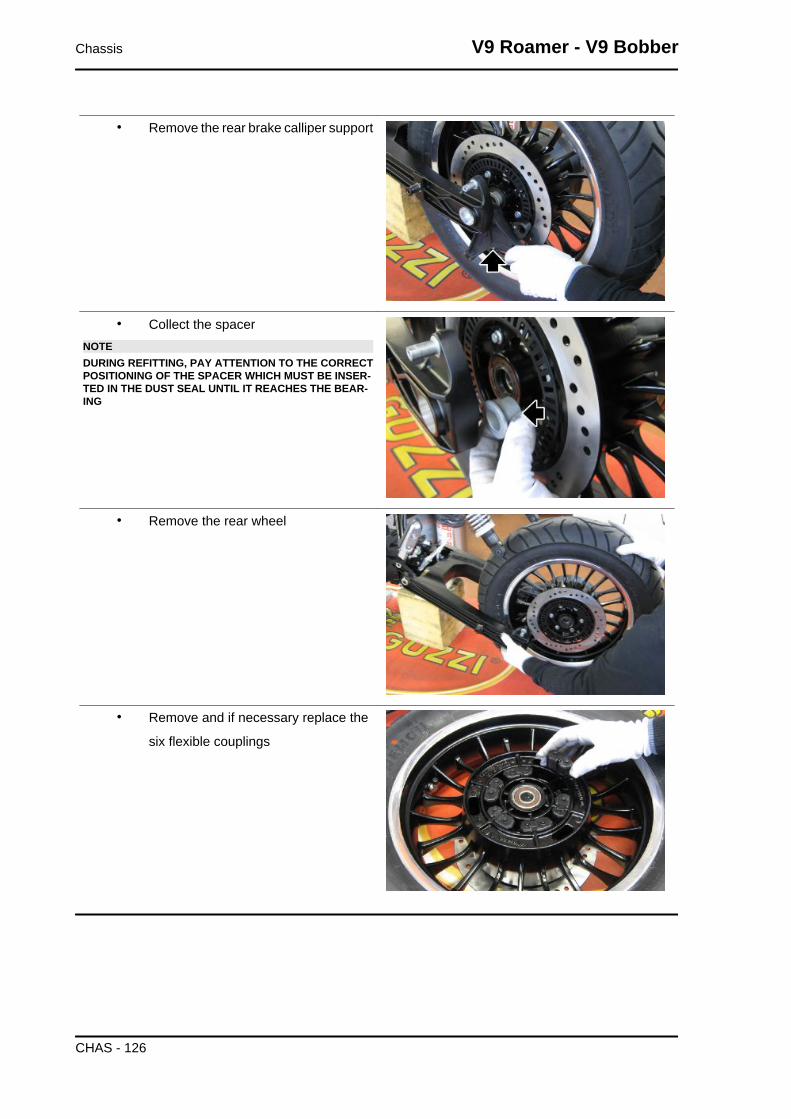
• Remove the rear brake calliper support
• Collect the spacerNOTEDURING REFITTING, PAY ATTENTION TO THE CORRECTPOSITIONING OF THE SPACER WHICH MUST BE INSER-TED IN THE DUST SEAL UNTIL IT REACHES THE BEAR-ING
• Remove the rear wheel
• Remove and if necessary replace the
six flexible couplings
Chassis V9 Roamer - V9 Bobber
CHAS - 126

• Remove the dust seal
• Remove the locking Seeger ring of the
bearing from the side where the en-
coder/brake disc wheel is present
• Using a generic bearing extractor remove the bearings from both sides
Swinging arm
V9 Roamer - V9 Bobber Chassis
CHAS - 127

SWINGARMpos. Description Type Quantity Torque Notes
1 Pins fixing swingarm to gearbox - 2 - Manual2 Locknuts fixing swingarm to gearbox - 2 50 Nm (36.88 lb ft) -3 Torx screws fastening rubber bel-
lows- 3 6 Nm (4.43 lb ft) -
Removing
• Remove the mufflers, the rear wheel,
and the brake calliper support com-
plete with clamp / ABS sensor, and
disconnect the shock absorbers from
the support pins.
• Remove the fixing nut of the cable
grommet plate and disconnect it from
the swingarm
• Cut the sealing clamp and lift the fold-
ingCAUTIONPAY ATTENTION NOT TO CUT AND DAMAGE THE RUB-BER FOLDING
• Unscrew the nuts on both sides of the
swingarm
Chassis V9 Roamer - V9 Bobber
CHAS - 128

• Loosen the pins so that the oscillating
swingarm can be removed from the
gearbox.
• Remove the complete swingarm from
the gearbox
• Remove the three screws (1) to re-
move the folding (2) complete with re-
taining ring (3)
Checking
• Check that the universal joint is not damaged, the gear teeth inserting in the sleeve grooves
and the grooves on the joint are not deformed or damaged; otherwise, replace the joint.
• Check that the rubber bellows are not cut or pierced; otherwise, replace it.
• Check that the swingarm pin threads and the swingarm fixing nuts are not damaged, de-
formed or flattened; otherwise, replace them.
• Check that the sleeve grooves are not damaged, deformed or deteriorated; otherwise, re-
place the sleeve.
• Check that the sleeve outer toothing and internal grooves are not damaged.
V9 Roamer - V9 Bobber Chassis
CHAS - 129

Bevel gears
REAR TRANSMISSIONpos. Description Type Quantity Torque Notes
1 Swingarm torx SHC fixing screws onthe transmission housing
M8x35 4 25 Nm (18.44 lb ft) -
Chassis V9 Roamer - V9 Bobber
CHAS - 130
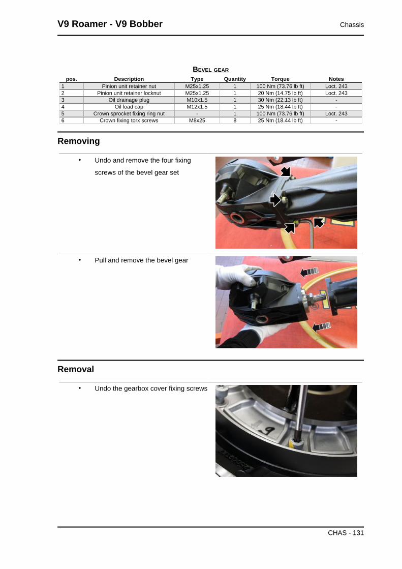
BEVEL GEARpos. Description Type Quantity Torque Notes
1 Pinion unit retainer nut M25x1.25 1 100 Nm (73.76 lb ft) Loct. 2432 Pinion unit retainer locknut M25x1.25 1 20 Nm (14.75 lb ft) Loct. 2433 Oil drainage plug M10x1.5 1 30 Nm (22.13 lb ft) -4 Oil load cap M12x1.5 1 25 Nm (18.44 lb ft) -5 Crown sprocket fixing ring nut - 1 100 Nm (73.76 lb ft) Loct. 2436 Crown fixing torx screws M8x25 8 25 Nm (18.44 lb ft) -
Removing
• Undo and remove the four fixing
screws of the bevel gear set
• Pull and remove the bevel gear
Removal
• Undo the gearbox cover fixing screws
V9 Roamer - V9 Bobber Chassis
CHAS - 131

• Using the suitable special tool, heat the
perimeter of the cover
Specific tooling020151Y Air heater
• If available, use the threaded stud bolts
as a guide to remove the cover. Turn
the complete box and tapping it on a
flat surface, remove the cover.
• Slide off the complete cover from the
crown.
• Remove the crown axle thickness.
Chassis V9 Roamer - V9 Bobber
CHAS - 132

• Remove the inside spacer.
• Collect the washer.
• Remove the needle bearing.
• Using a suitable tool, disengage the ra-
dial snap ring.
V9 Roamer - V9 Bobber Chassis
CHAS - 133

• Remove the radial snap ring.
• Using the special tool, heat the seat of
the outer track of the needle bearing.
Specific tooling020151Y Air heater
• Insert the special tool under the washer
and screw the cursor.
Specific tooling001467Y036 Extract the inner bearing track
• Insert a suitable bushing on the proper
tool and screw the nut while holding the
extractor.
Chassis V9 Roamer - V9 Bobber
CHAS - 134

• Remove the outer track of the needle
bearing.
• Remove the washer.
• Remove the sealing ring. When reas-
sembling use a new ring.
• Using a suitable tool, remove the radial
snap ring.
V9 Roamer - V9 Bobber Chassis
CHAS - 135

• Using special tool, unscrew the ring
nut. At the end of the thread, screw un-
til it stops in such a way as to create the
space between the same ring nut and
the shoulder washer.
Specific tooling020999Y Crown ring nut key
• Insert the special tool under the shoul-
der washer and screw the cursor.
Specific tooling19.90.70.00 Extractor for internal ring on drilledbolt
• Remove the inner track of the needle
bearing.
• Remove the shoulder washer.
Chassis V9 Roamer - V9 Bobber
CHAS - 136

• Remove the ring nut.
• Remove the crown gear.
• Remove the cover from the gearbox of
the splash guard hub.
• Remove the O-ring. When reassem-
bling use a new O-ring.
V9 Roamer - V9 Bobber Chassis
CHAS - 137

• Rotate the cover and remove the seal
ring. When reassembling use a new
seal ring.
• Using special tool, unscrew the pinion
bearings case.
Specific tooling020998Y Pinion case key
• Remove the complete pinion from its
seat.
• Using the special tool, lock in the vice,
unscrew fastening nut and lock nut of
the pinion case bearing.
Specific tooling021000Y Bevel gear pair support
Chassis V9 Roamer - V9 Bobber
CHAS - 138

• Remove the spacer closing bearings.
• Remove the sealing ring.
• Remove the O-ring.
Checking
• After assembly of the box, it is neces-
sary to check the play between the
pinion and the crown. Clamp in a vice
and install a dial gauge by means of a
suitable support. The dial gauge tester
must be placed the outer end of a tooth
positioned at 90°.
CharacteristicMaximum clearance allowed0.10-0.15 mm (0.004-0.006 in)
V9 Roamer - V9 Bobber Chassis
CHAS - 139

Assembling
• Insert the new O-ring in the pinion unit,
or use the one removed during the dis-
mantling phase if it is intact and un-
damaged
• Insert the seal ring until it stops
• Insert the spacer closing bearings pay-
ing attention that the manufactured
part is facing the O-ring so as not to
damage it
• Using the special tool, lock in the vice,
screw the fastening nut and lock nut of
the pinion case bearing to torque.
Specific tooling021000Y Bevel gear pair support
Chassis V9 Roamer - V9 Bobber
CHAS - 140

• Insert the complete pinion in its seat.
• Using special tool, screw the pinion
bearings case.
Specific tooling020998Y Pinion case key
• Using the special tool, insert a new seal
ring in the cover.
• On the opposite side of the cover, in-
sert a new O-ring.
• Replace the sprocket hub cover.
• Replace the crown and the fastening
ring nut.
Specific tooling021005Y Punch seals on the bevel gear cover
• Screw the ring nut on the crown to the
prescribed torque.
V9 Roamer - V9 Bobber Chassis
CHAS - 141

• Insert the shoulder washer. Using the
special tool, insert the inner track of the
needle bearing. Insert the radial snap
ring.
Specific toolingGU19927900 Punch for pressing bearing innerring onto drilled pin
• Reposition the crown axle thickness.NOTETHE THICKNESS HAS A UNIQUE POSITION IN THE BOX.PAY ATTENTION TO THE CORRECT POSITION BYCHECKING THE CORRESPONDENCE OF THE HOLESWITH THE FASTENING SCREWS.
• Replace the complete cover of the hub
in the box.
• Screw to torque the cover fixing
screws.
Chassis V9 Roamer - V9 Bobber
CHAS - 142
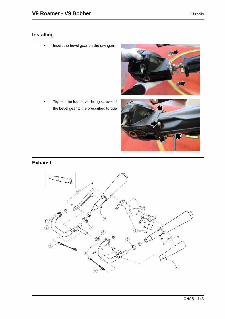
Installing
• Insert the bevel gear on the swingarm
• Tighten the four cover fixing screws of
the bevel gear to the prescribed torque
Exhaust
V9 Roamer - V9 Bobber Chassis
CHAS - 143
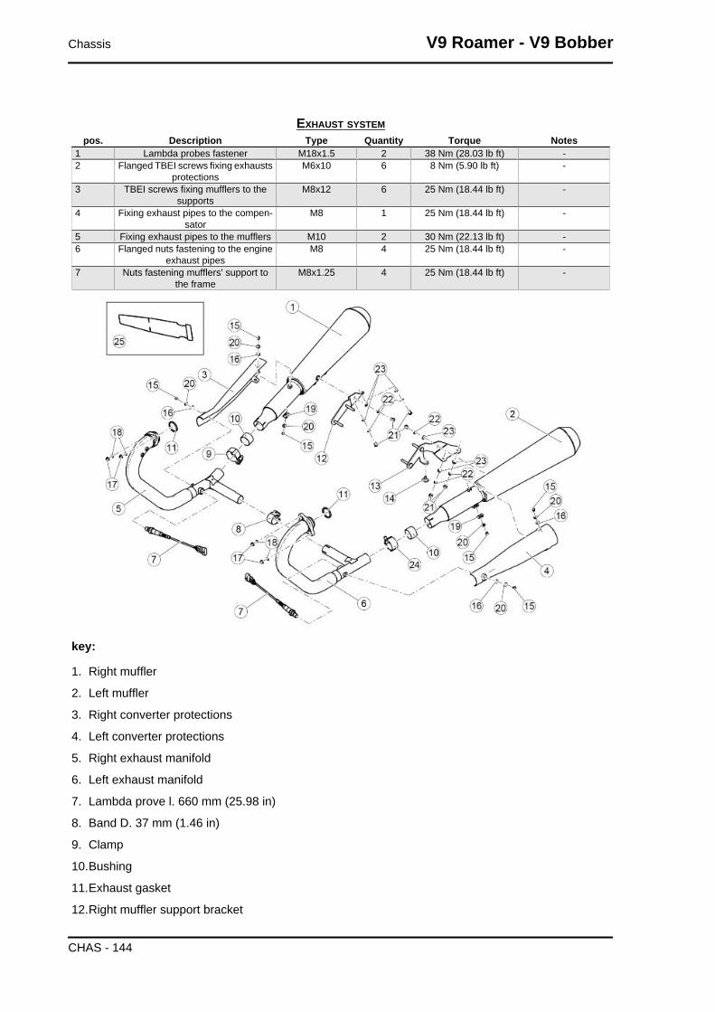
EXHAUST SYSTEMpos. Description Type Quantity Torque Notes
1 Lambda probes fastener M18x1.5 2 38 Nm (28.03 lb ft) -2 Flanged TBEI screws fixing exhausts
protectionsM6x10 6 8 Nm (5.90 lb ft) -
3 TBEI screws fixing mufflers to thesupports
M8x12 6 25 Nm (18.44 lb ft) -
4 Fixing exhaust pipes to the compen-sator
M8 1 25 Nm (18.44 lb ft) -
5 Fixing exhaust pipes to the mufflers M10 2 30 Nm (22.13 lb ft) -6 Flanged nuts fastening to the engine
exhaust pipesM8 4 25 Nm (18.44 lb ft) -
7 Nuts fastening mufflers' support tothe frame
M8x1.25 4 25 Nm (18.44 lb ft) -
key:
1. Right muffler
2. Left muffler
3. Right converter protections
4. Left converter protections
5. Right exhaust manifold
6. Left exhaust manifold
7. Lambda prove l. 660 mm (25.98 in)
8. Band D. 37 mm (1.46 in)
9. Clamp
10.Bushing
11.Exhaust gasket
12.Right muffler support bracket
Chassis V9 Roamer - V9 Bobber
CHAS - 144

13.Left muffler support bracket
14.Rubber ring
15.TBEI flanged screw M6x10
16.Elastic spacer
17.Flanged nut M8
18.Washer 8.4x13x0.8
19.Elastic plate M6
20.Washer
21.TBEI Screws M8x12 conic
22.Washer 8.4x13x0.8
23.Washer 8.4x15x1.5
24.Clamp
25.Heat-protecting cover
Removing the tail pipe
The engine and the exhaust system components get very hot and remain in this condition for a certain
time interval after the engine has been switched off. Before handling these components, make sure that
you are wearing insulating gloves or wait until the engine and the exhaust system have cooled down.
• Remove the three fixing screws of the silencer protection
V9 Roamer - V9 Bobber Chassis
CHAS - 145

• Remove the silencer protection
• Remove the three fastening screws of
the silencer to the support bracket
• Loosen the clamp between the silencer
and manifold
• Slide and remove the silencer from the
collector
NOTE
THE OPERATIONS FOR REMOVING THE EXHAUST TERMINAL, APPLY TO BOTH ENDS
Chassis V9 Roamer - V9 Bobber
CHAS - 146
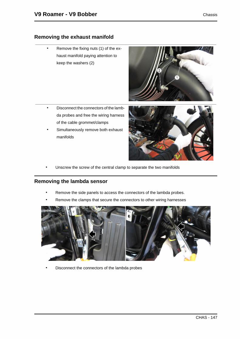
Removing the exhaust manifold
• Remove the fixing nuts (1) of the ex-
haust manifold paying attention to
keep the washers (2)
• Disconnect the connectors of the lamb-
da probes and free the wiring harness
of the cable grommet/clamps
• Simultaneously remove both exhaust
manifolds
• Unscrew the screw of the central clamp to separate the two manifolds
Removing the lambda sensor
• Remove the side panels to access the connectors of the lambda probes.
• Remove the clamps that secure the connectors to other wiring harnesses
• Disconnect the connectors of the lambda probes
V9 Roamer - V9 Bobber Chassis
CHAS - 147

• Remove the clamps that secure the wiring harnesses of the Lambda proves
• Release the wiring harness from the
grommet cable
• Unscrew and remove the lambda probes
Chassis V9 Roamer - V9 Bobber
CHAS - 148

INDEX OF TOPICS
BRAKING SYSTEM BRAK SYS

ABS
ABS SYSTEMpos. Description Type Quantity Torque Notes
1 Control unit bracket fastening to theframe
M6x16 2 10 Nm (7.38 lb ft) -
2 Screws fastening the ABS modulatorto the support
M6x20 3 10 Nm (7.38 lb ft) -
3 SHC screw fastening the brake pipesfixing plate
M4x16 1 3 Nm (2.21 lb ft) -
4 SHC screw fastening the cablegrommet plate
M5x12 1 6 Nm (4.43 lb ft) -
Braking system V9 Roamer - V9 Bobber
BRAK SYS - 150

key:
1. ABS ECU control unit
2. Front ABS sensor
3. Rear ABS sensor
4. Battery
5. Main relay
6. ECU
7. Instrument panel
8. K line (diagnosis)
9. Key
10.Fuses
ABS ECU control unit pin configuration
• PIN 1 - GND - Ground
• PIN 2 - PCC1 - Vehicle identification ground connection
• PIN 4 - IGN - Injection
• PIN 8 - WL - Alarm warning light
• PIN 11 - R_SIGN - Rear ABS sensor signal
• PIN 12 - R_GND - Rear ABS sensor ground connection
• PIN 13 - F_GND - Front ABS sensor ground connection
• PIN 14 - F_SIG - Front ABS sensor signal
• PIN 15 - PCC2 - Vehicle identification ground connection
V9 Roamer - V9 Bobber Braking system
BRAK SYS - 151

• PIN 16 - ISO_K - K line (diagnosis)
• PIN 18 - KL30 - Power supply
Foreword
key:
1. ABS control unit
2. ABS control unit support bracket
3. Oil pipe screw
4. Washer 10x14x1.6
5. Screw 6x20
6. Washer 6.6x18x1.6
7. Rubber ring
8. T-shaped bushing
9. ABS HECU pipe - Front pump
10.ABS HECU pipe - Front clamp
11.ABS HECU pipe - Rear pump
12.Stud bolt
13.SHC screw M4x16
14.Pipe fixing plate
15.Low self-locking nut
16.Nut
Braking system V9 Roamer - V9 Bobber
BRAK SYS - 152

17.Brake pipe mounting plate
18.Cable guide
19.Clamp
20.M5x12 SHC screw
21.Ring
Operating diagram
V9 Roamer - V9 Bobber Braking system
BRAK SYS - 153

ABS functional diagram key
1. Front system circuit
2. Front brake pump
3. Front brake lever
4. Rear system circuit
5. Rear brake pump
6. Rear brake pedal control
7. ABS control unit
8. Rear brake calliper
9. Front Calliper
10.Front brake circuit intake solenoid valve (normally open)
11.Humidifier
12.Rear brake circuit intake solenoid valve (normally open)
13.Rear brake exhaust circuit solenoid valve (normally closed)
14.Rear/front brake circuit low pressure accumulator
15.Front brake exhaust circuit solenoid valve (normally closed)
16.DC electric motor
17.Double circuit hydraulic pump (ABS)
18.Rear brake reservoir
19.Front brake reservoir
ABS OPERATION
General specifications:
The front circuit is similar to the rear circuit.
• The ABS inlet valve (10 - 12) is normally open and it is closed only when the system inter-
venes to avoid wheel locking.
• The exhaust valve (13 - 15) is normally closed and it is opened only when the system in-
tervenes to avoid wheel locking.
• When the system is in standby, the ABS processor never stops monitoring the speed of the
wheels in order to assess potential wheel slippage.
• When in standby, the system does not intervene at all when the rider brakes; the braking
system is the same as the one without ABS.
Stages in ABS cycle (the following operations refer to the front circuit but are also applicable to
the rear one):
A - Brake activation: the rider starts braking as he would usually do.
B - Pressure reduction: it coincides with danger recognition (wheel slippage above threshold): the
system closes the inlet valve (10-12) and opens the exhaust valve (13-15) temporarily.
Braking system V9 Roamer - V9 Bobber
BRAK SYS - 154

At this stage the rider cannot increase the pressure on the callipers (8-9) and the system reduces the
pressure on the callipers partially. The excess fluid temporarily fills the front reservoir (18-19) until the
ABS pump (17) self-activates and delivers the fluid back to the brake pump (2-5).
C - Pressure maintained: the pressure in the callipers (8-9) remains low until total recovery of speed /
wheel grip.
The system restores the fluid taken from the calliper (8-9) in the section of the system between the
brake pump (2-5) and the ABS inlet valve (10-12).
D - Pressure restored: by opening the inlet valve (10-12) momentarily, the pressure of the callipers
(8-9) is increased until maximum deceleration is reached. Then, the system gives the control over the
braking back to the rider.
E - If the wheel does not reach complete grip, the system continues operating as before until complete
grip is obtained or until the vehicle stops. An error can be detected if the duration of the pressure
reduction phase exceeds the pre-set time limit.
ABS SYSTEM DESCRIPTION
The ABS system is a device to avoid wheels locking in case of emergency braking, increasing vehicle
braking stability when compared to a traditional braking system.
Sometimes when the brake is operated, the tyre locks with a consequent loss of grip, which makes it
difficult to control the vehicle. A position sensor (3) on the tone wheel (2), forming an integral unit with
the vehicle wheel, "reads" the status of the vehicle wheel spotting any possible lock.
A control unit (1) signals this out and adjusts the pressure in the braking circuit accordingly.NOTEWHEN THE ABS SYSTEM STARTS WORKING, A VIBRATION IS FELT ON THE BRAKE LEVER.
THE WHEEL ANTILOCK BRAKING SYSTEM DOES NOT PREVENT FALLS WHILE ON A BEND.AN EMERGENCY BRAKING WITH THE VEHICLE INCLINED, HANDLE BAR TURNED, ON UN-EVEN OR SLIPPERY ROADS, OR WITH POOR GRIP CREATES LACK OF STABILITY DIFFICULTTO HANDLE. THEREFORE, RIDE CAREFULLY AND SENSIBLY AND ALWAYS BRAKE GRADU-ALLY. BRAKING WHILE TURNING A CORNER IS SUBJECT TO LAWS OF PHYSICS WHICH NOTEVEN ABS CAN ELIMINATE.
When the sensors (3) detect a significant speed difference between the rear and the front wheels (for
example, when rearing up on the back wheel), the ABS system could take this as a dangerous situation.
V9 Roamer - V9 Bobber Braking system
BRAK SYS - 155

In this case, two things may occur:
• The ABS system intervenes by releasing pressure from the calliper until the wheel turns
again at the same speed of the other wheel. It is not possible to brake for an instant.
• if the speed difference lasts long, the system may detect an error and deactivate the ABS
system. As a consequence, the system works like any regular braking system.
Riding with an active ABS system
• When turning the key on, the ABS
warning light turns on and flashes until
reaching 5 km/h (3.11 mph); at this
point it turns off.CAUTION
THE STEADY LIGHTING OR THE CONTINUOUS FLASHINGOF THE ABS WARNING LIGHT INDICATES THE PRES-ENCE OF AN ANOMALY AND THE DEACTIVATION OF THEABS FUNCTIONALITY.
20 A fuse (ABS Main fuse) (6)
Protects: ABS Control unit.
Guide to diagnosis
PREMISE
Each time the key is ON, at least one current or stored* error of the ABS system is often detected:
• the ABS warning light turns on permanently
The ABS system is deactivated!
The system operates perfectly just as any other braking system without ABS
* The diagnosis requires exceeding the 5 km/h.
Each time the key is ON, if at least one current or stored* error of the ABS system is not detected:
• the ABS warning light flashes
When the 5 km/h (3.11 mph) are exceeded:
- if errors are not detected
Braking system V9 Roamer - V9 Bobber
BRAK SYS - 156
• the ABS warning light turns off
- if at least one malfunction is detected
• the ABS warning light turns on permanently
The ABS system is deactivated!
The system operates perfectly just as any other braking system without ABS.
The detection of malfunctions may require more or less time according to the type of failure.
Error detection logic foresees that for the errors to be diagnosed one or more conditions must persist
within a given time.
If during this given time one of the conditions is missing but then it comes back, the timer is reset and
the system is no longer able to diagnose the error.
The ABS system is still inactive.
Example:
- error code 5D93 requires some minutes before it is diagnosed during the given time:
• the ABS warning light ABS keeps flashing
GUIDE TO ABS FAULT DIAGNOSIS
1. ABS LAMP ON
2. CONNECT PADS
PADS COMMUNICATE? (NO, go to 3; YES, go to 4)
3. PERFORM THESE CHECKS:
• A. PIN 1 Ground connection
• B. +12V at PIN 18
• C. +12V at PIN 4 with key ON
4. ARE THERE ANY ERRORS? YES, go to point 5; NO, go to 6)
5. CHECK THE ERRORS TABLE
6. ABS WARNING LIGHT ACTIVATION
IS IT ACTIVATED?(YES, go to point 7; NO, go to point 8)
7. CONTACT TECHNICAL SERVICE
8. PERFORM THESE CHECKS:
• A. Cable continuity between PIN8 of the ABS control unit connector and the instrument panel
warning light.
• B. Check connectors - refer to the operations described in the chapter
If the above checks are OK, the causes can be:
• C. ABS Control unit malfunction
• D. Instrument panel malfunction
V9 Roamer - V9 Bobber Braking system
BRAK SYS - 157

NOTE: to carry out a check using the diagnostic tool on the wheel speed sensor, refer to the
operations described in chapter ""ELECTRICAL SYSTEM/CHECKS AND CONTROLS/SPEED
SENSOR" chapter.
Use of diagnostics instrument for ABS system
Abs screen pages
ECU INFO screen page
This screen page shows general data regarding
the control unit, for example software type, map-
ping, control unit programming date
PARAMETERS screen page
This screen page shows the parameters meas-
ured by the several sensors (engine revs, engine
temperature, etc.) or values set by the control unit
(injection time, ignition advance, etc.)
PARAMETERSP.A.D.S. characteristic Value/example Unit of
measurement
Notes
Front wheel speed - km/h -Rear wheel speed - km/h -Battery voltage - V -Front brake circuit pressure - bar -
Quality test of the sensors
When turning the wheel or acting on the brake, a variation of parameters must be detected.
Braking system V9 Roamer - V9 Bobber
BRAK SYS - 158

ACTIVATION screen page
This screen page is used to delete errors in the
control unit memory and to activate some systems
controlled by the control unit.
ACTIVATIONP.A.D.S. characteristic Value/example Unit of
measurement
Notes
ABS warning lightError clearingFreezes and saves the parameterand states values
ERRORS screen page
This screen page displays any errors detected in
the vehicle (ATT) or stored in the control unit
(MEM) and you can check that the cancellation of
error (STO) has taken place.
ERRORSP.A.D.S. characteristic. Value/example Units of
measurement
Notes
Comparison of front and rear wheel C1024 Excessive differenceRear wheel speed sensor electricaldiagnosis
C1031 Short circuit or open circuit to negative or shortcircuit to positive
Rear wheel speed sensor functionaldiagnosis
C1032 Signal not valid
Front wheel speed sensor electricaldiagnosis
C1033 Short circuit or open circuit to negative or shortcircuit to positive
Front wheel speed sensor functionaldiagnosis
C1034 Signal not valid
Inside error C1014 Solenoid valve relay failureInside error C1015 Recirculation pump failureInside error C1021 Control unit failureInside error C1048 Rear circuit output solenoid valve failureInside error C1049 Rear circuit output solenoid valve failureInside error C1052 Rear circuit input solenoid valve failureInside error C1054 Front circuit inlet solenoid valve failure
V9 Roamer - V9 Bobber Braking system
BRAK SYS - 159

P.A.D.S. characteristic. Value/example Units ofmeasure
ment
Notes
Low power supply voltage C1058High power supply voltage C1059Configuration error C1089CAN error U2921 Controller errorCAN error U2922 Line failure (busoff)CAN error U2924 Failed reception from instrument panelCAN error U2925 Failed reception from injection ECU+ button U2926 Connect to the injection control unit diagnostics- button U2927 Connect to the injection control unit diagnosticsInside error C1331 Pressure sensor failureInside error C1332 Pressure sensor failure (Offset)Inside error C1333 Pressure sensor failure (Power supply)
PADS report mode
In the following are described the procedure to be
performed through the diagnostic tool in order to
generate an errors report:
• When started the program, select the
brand.
• Select the vehicle and the component.
• Select Self-diagnosis.
• Go to the page Error codes.
Braking system V9 Roamer - V9 Bobber
BRAK SYS - 160

• Select an error and show the Ambient
parameter error(where provided).
• Repeat the operation by selecting each
error and showing the corresponding
Ambient parameter error (where provi-
ded).
• Go to the page Report and then on
Print and select the virtual PDF printer.
V9 Roamer - V9 Bobber Braking system
BRAK SYS - 161

• If there is no PDF printer, there are
several free programs, ask the infor-
mation systems to install it.
• Name the file with a name that contains
the main information of the vehicle and
the analysed component e.g. CN1200-
Chassis0465-Instrument panel.
Modulator
Before removing the modulator, it is necessary
to completely purge the braking system.
MODULATOR REMOVAL
• Remove the horn.
• Disconnect the connector (1).
• With a felt-tip pen, mark a reference on
the pipes and on the ABS control unit
to avoid inverting them when refitting
• Remove the oil pipes in the order (3) -
(4) - (6) - (5)
• Unscrew the nut of the oil pipe (3) and
cover both the pipe and the hole on the
modulator.
Braking system V9 Roamer - V9 Bobber
BRAK SYS - 162

• Remove the fixing screw from the volt-
age regulator that holds the support
bracket of the ABS control unit.
• Operating from the left side of the mo-
torcycle, remove the ABS modulator
• To remove the ABS modulator from the
support, remove the three fixing
screws
Rear brake calliper
Tightening torque
V9 Roamer - V9 Bobber Braking system
BRAK SYS - 163

REAR BRAKE CALLIPERpos. Description Type Quantity Torque Notes
1 Flanged TE screws fixing rear brakecalliper
M8x30 2 25 Nm (18.44 lb ft) -
2 Rear brake calliper support pin M16 1 35 Nm (25.81 lb ft) -
Rear brake calliper components
key:
Braking system V9 Roamer - V9 Bobber
BRAK SYS - 164

1. Rear brake calliper
2. TE Flanged screw
3. Rear brake calliper support
4. Pin
5. Brake pads copy
6. Bleed with hood
7. Pins and springs kit
Removal
• Obtain a special container and empty
the system
• Remove the screw fixing the brake
pipe to the clamp
• Remove the two calliper fixing screws
• Remove the calliper
Front brake calliper
Tightening torque
V9 Roamer - V9 Bobber Braking system
BRAK SYS - 165

FRONT BRAKE CALLIPERpos. Description Type Quantity Torque Notes
1 Brake calliper fixing screws M10x30 2 50 Nm (36.88 lb ft) -
Front brake calliper components
key:
1. Front brake calliper
Braking system V9 Roamer - V9 Bobber
BRAK SYS - 166

2. SHC screws M10x1.25
3. Bleed with hood
4. Spring
5. Pins and spring clamp
6. Brake pads
Removal
• Obtain a special container and empty
the system
• Remove the screw fixing the brake
pipe to the clamp
• Remove the two calliper fixing screws
• Remove the calliper
Rear brake disc
Tightening torque
V9 Roamer - V9 Bobber Braking system
BRAK SYS - 167

REAR WHEELpos. Description Type Quantity Torque Notes
1 Rear wheel axle fixing nut M20 1 120 Nm (88.51 lb ft) -2 Flanges TE screws fastening phonic
wheel and brake discM8x22 6 25 Nm (18.44 lb ft) Loct. 243
3 SHC screws fastening ABS sensorsupport
M6x12 2 10 Nm (7.38 lb ft) -
Removal
• Remove the rear wheel
• Remove the six fixing screws (1) of the
tone wheel and the front disc
Braking system V9 Roamer - V9 Bobber
BRAK SYS - 168

• Remove the tone wheel (2)
• Remove the brake disc (3)
DURING REFITTING, APPLY LOCTITE 243 ON THETHREAD OF THE BRAKE DISC SCREWS (1).CAUTIONDURING REFITTING, SCREW ALL THE SCREWS (1) MAN-UALLY AND TIGHTEN THEM OPERATING DIAGONALLYFOLLOWING THIS SEQUENCE: A-B-C-D-E-F.
Disc InspectionCAUTION
THE BRAKE DISC SHAPE DOES NOT CHANGE THE OPERATING AND MAINTENANCE SPECI-FICATIONS OF THE SYSTEM.
• The following operations are to be car-
ried out with brake disc fitted on the
wheel.
• Check the disc for wear by measuring
the minimum thickness with a micro-
meter in different points. If the mini-
mum thickness, even in a single point
V9 Roamer - V9 Bobber Braking system
BRAK SYS - 169

of the disc, is less than the minimum
value, replace the disc.
Disc thickness minimum value: 4.5 mm (0.18
in)
Front brake disc
Tightening torque
FRONT WHEELpos. Description Type Quantity Torque Notes
1 Front wheel axle M18 1 80 Nm (59.00 lb ft) -2 Phonic wheel/brake disc fastening screws M8x18 6 25 Nm (18.44 lb ft) Loct. 243
Removal
• Remove the rear wheel
• Remove the six fixing screws (1) of the
tone wheel and the front disc
Braking system V9 Roamer - V9 Bobber
BRAK SYS - 170

• Remove the tone wheel (2)
• Remove the brake disc (3)
DURING REFITTING, APPLY LOCTITE 243 ON THETHREAD OF THE BRAKE DISC SCREWS (1).CAUTIONDURING REFITTING, SCREW ALL THE SCREWS (1) MAN-UALLY AND TIGHTEN THEM OPERATING DIAGONALLYFOLLOWING THIS SEQUENCE: A-B-C-D-E-F.
Disc InspectionCAUTION
THE FRONT BRAKE DISC SHAPE DOES NOT CHANGE THE OPERATING AND MAINTENANCESPECIFICATIONS OF THE SYSTEM.
• The following operations must be car-
ried out with the brake discs fitted on
the wheel; they refer to a single disc,
but are valid for both.
• Check the disc for wear by measuring
the minimum thickness with a micro-
meter in different points. If the mini-
mum thickness, even in a single point
V9 Roamer - V9 Bobber Braking system
BRAK SYS - 171

of the disc, is less than the minimum
value, replace the disc.
Disc thickness minimum value: 4 mm (0.16 in)
• Using a dial gauge, check that the max-
imum oscillation of the disc does not
exceed the tolerance; otherwise, re-
place it.
Disc oscillation tolerance: 0.15 mm (0.0059 in)
Front brake pads
Removal
• Remove the Seeger locking the retain-
ing pins of the brake pads
• Remove the brake pad retaining pins
• Collect the protection plate.
Braking system V9 Roamer - V9 Bobber
BRAK SYS - 172

• Remove the brake pads
Rear brake pads
Removal
• Remove the rear brake calliper
• Remove the screws locking the brake
pads
• Remove the brake pads
V9 Roamer - V9 Bobber Braking system
BRAK SYS - 173

Bleeding the braking system
Front
Any air trapped in the hydraulic circuit acts as a cushion, absorbing much of the pressure applied by
the brake pump and minimising the braking power of the calliper.
The presence of air is signalled by the "sponginess" of the brake control and by poor braking efficiency.CAUTION
CONSIDERING THE DANGER FOR VEHICLE AND RIDER, IT IS STRICTLY NECESSARY, AFTERREFITTING BRAKES AND RESTORING THE BRAKING SYSTEM TO THE REGULAR USE CON-DITIONS, THAT THE HYDRAULIC CIRCUIT BE AIR PURGED.NOTE
THE VEHICLE MUST BE ON LEVEL GROUND TO BE PURGED. WHILE PURGING THE HYDRAUL-IC SYSTEM, FILL THE RESERVOIR WITH THE NECESSARY QUANTITY OF BRAKE FLUID.CHECK THAT, DURING THE OPERATION, THERE IS ALWAYS BRAKE FLUID IN THE RESER-VOIR.
The bleeding procedure can be performed in a traditional way or using specific tools such as vacuum
pumps or similar.
In the following is shown the "traditional" bleeding procedure.
• Remove the rubber protection cover
from the bleed valve.
• Insert the transparent plastic pipe in
the front brake calliper bleed valve and
slide the other end of this pipe in a con-
tainer to collect the fluid.
• Remove the front brake fluid reservoir
cap.
• Operate the brake lever and then open
the bleed valve on the calliper 1/4 of a
turn to let the air out.
• Close the bleed again before reaching
the lever end of the stroke and repeat
the operation until there is no air.
Braking system V9 Roamer - V9 Bobber
BRAK SYS - 174

• Repeat the procedure for both callip-
ers.
• Screw the bleeding valve and remove the pipe.
• Top-up the reservoir until the correct brake fluid level is obtained.
• Refit and block the front brake oil reservoir cap.
• Refit the rubber protection cover.
Rear
Any air trapped in the hydraulic circuit acts as a cushion, absorbing much of the pressure applied by
the brake pump and minimising the braking power of the calliper.
The presence of air is signalled by the "sponginess" of the brake control and by poor braking efficiency.CAUTION
CONSIDERING THE DANGER FOR VEHICLE AND RIDER, IT IS STRICTLY NECESSARY, AFTERREFITTING BRAKES AND RESTORING THE BRAKING SYSTEM TO THE REGULAR USE CON-DITIONS, THAT THE HYDRAULIC CIRCUIT BE AIR PURGED.NOTE
THE VEHICLE MUST BE ON LEVEL GROUND TO BE PURGED. WHILE PURGING THE HYDRAUL-IC SYSTEM, FILL THE RESERVOIR WITH THE NECESSARY QUANTITY OF BRAKE FLUID.CHECK THAT, DURING THE OPERATION, THERE IS ALWAYS BRAKE FLUID IN THE RESER-VOIR.
• Remove the rubber protection cover
from the bleed valve.
• Insert the transparent plastic pipe in
the rear brake calliper bleed valve and
insert the other end of this pipe into a
container to collect the fluid.
• Remove the rear brake fluid reservoir
cap.
• Operate the brake lever and then open
the bleed valve on the calliper 1/4 of a
turn to let the air out.
V9 Roamer - V9 Bobber Braking system
BRAK SYS - 175

• Close the bleed again before reaching
the lever end of the stroke and repeat
the operation until there is no air.
• Screw the bleeding valve and remove the pipe.
• Top-up the reservoir until the correct brake fluid level is obtained.
• Refit and lock the rear brake oil reservoir cap.
• Refit the rubber protection cover.
Front brake pump
Tightening torque
FRONT BRAKE PUMPpos. Description Type Quantity Torque Notes
1 Brake pump U-bolt fixing screws M6x25 2 10 Nm (7.38 lb ft) -2 Brake pump control pin M6 1 10 Nm (7.38 lb ft) -
Braking system V9 Roamer - V9 Bobber
BRAK SYS - 176
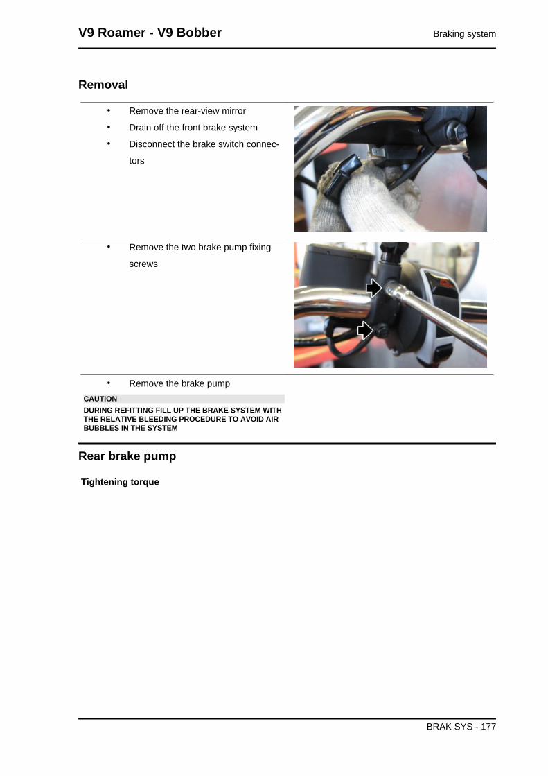
Removal
• Remove the rear-view mirror
• Drain off the front brake system
• Disconnect the brake switch connec-
tors
• Remove the two brake pump fixing
screws
• Remove the brake pumpCAUTIONDURING REFITTING FILL UP THE BRAKE SYSTEM WITHTHE RELATIVE BLEEDING PROCEDURE TO AVOID AIRBUBBLES IN THE SYSTEM
Rear brake pump
Tightening torque
V9 Roamer - V9 Bobber Braking system
BRAK SYS - 177
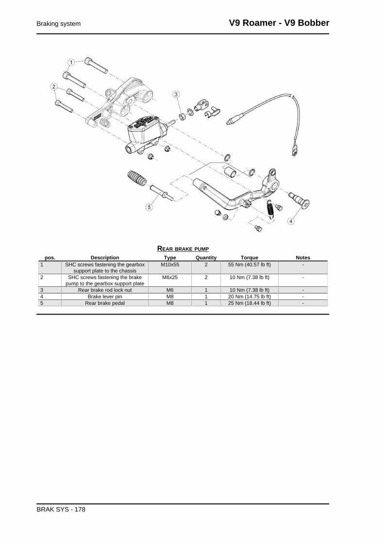
REAR BRAKE PUMPpos. Description Type Quantity Torque Notes
1 SHC screws fastening the gearboxsupport plate to the chassis
M10x55 2 55 Nm (40.57 lb ft) -
2 SHC screws fastening the brakepump to the gearbox support plate
M6x25 2 10 Nm (7.38 lb ft) -
3 Rear brake rod lock nut M6 1 10 Nm (7.38 lb ft) -4 Brake lever pin M8 1 20 Nm (14.75 lb ft) -5 Rear brake pedal M8 1 25 Nm (18.44 lb ft) -
Braking system V9 Roamer - V9 Bobber
BRAK SYS - 178

INDEX OF TOPICS
BODYWORK BODYW

Disassembling the lock
• Remove the left side fairing
• Remove the fork spring
• Remove the cable support plate
• Extract the ignition switch assembly
externally
Taillight assy.
• Remove the license plate cover
• Remove the locking clamp of the tail-
light wiring harness / arrows and dis-
connect the connector
Bodywork V9 Roamer - V9 Bobber
BODYW - 180

• Remove the three fastening screws of
the headlight to the support bracket
• Remove the taillight together with the
wiring harness
• During reassembly, pay attention to
correctly position the present grommet
on the taillight wiring harness, the
groove of the license plate holder
Side body panels
Tightening torque
V9 Roamer - V9 Bobber Bodywork
BODYW - 181

CENTRAL BODYWORKPos. Description Type Quantity Torque Notes
1 TBEI screws fastening fearing M5x15 6 4 Nm (2.95 lb ft) -2 TE flanged screws fastening top
splash guardM6 2 10 Nm (7.38 lb ft) -
3 Flanged nuts fastening bottomsplash guard
M6 2 10 Nm (7.38 lb ft) -
THE OPERATIONS BELOW ARE VALID FOR
REMOVAL OF BOTH SIDE PANELS
• Remove the three side fairing fixing
screws
• To remove the left side fairing the sad-
dle opening cable must be unhooked
from the ignition switch assembly
Bodywork V9 Roamer - V9 Bobber
BODYW - 182

License plate holder
Air box
Tightening torque
FILTER BOXpos. Description Type Quantity Torque Notes
1 Air filter box cover fastening self-threading screw
M5x14 4 3 Nm (2.21 lb ft) -
2 SWP screws fixing filter box to chas-sis
M5x20 2 3 Nm (2.21 lb ft) -
3 SWP filter box locking screws M5x20 9 3 Nm (2.21 lb ft) -
• Remove the saddle, the side panels
and the battery complete with the rub-
ber support
• Slide from the support present in the
filter casing connector (1) and the ABS
fuses (2)
V9 Roamer - V9 Bobber Bodywork
BODYW - 183

• Remove the four fastening screws (3)
of the air filter cover
• Remove the air filter cover (4) and the
filter (5)
• Remove the two screws securing the
fuse box support and move it to have
greater freedom of movement for sub-
sequent operations
• Remove the two screws that fasten the
air filter case to the chassis
Bodywork V9 Roamer - V9 Bobber
BODYW - 184

• Remove the clamp present in the col-
lector that blocks the filter case to the
throttle body
• Remove the two bottom fastening nuts
of the splash guard
• Operating on the left side of the motorcycle, remove the blow-by pipe (6) from the filter case,
while the right side, remove the secondary air pipe (7)
• Remove the four screws securing the
filter case support bracket and remove
it by slightly raising the box itself
V9 Roamer - V9 Bobber Bodywork
BODYW - 185

• Pull the filter case from the right side of
the motorcycle
• Remove the collector from the filter
case
• Remove the locking screws from the
filter case
• Remove the cover (8) and the blow-by
filter (9)
Bodywork V9 Roamer - V9 Bobber
BODYW - 186

• Check and replace the two seals
present in the cover
V9 Roamer - V9 Bobber Bodywork
BODYW - 187

INDEX OF TOPICS
PRE-DELIVERY PRE DE

Carry out the listed checks before delivering the motorcycle.WARNING
HANDLE FUEL WITH CARE.
Aesthetic inspection
- Paintwork
- Fitting of Plastic Parts
- Scratches
- Dirt
Tightening torques inspection
- Safety fasteners:
front and rear suspension unit
front and rear brake calliper retainer unit
front and rear wheel unit
engine - chassis retainers
steering assembly
- Plastic parts fixing screws
Electrical system
- Main switch
- Headlamps: high beam lights, low beam lights, tail lights (front and rear) and their warning lights
- Headlight adjustment according to regulations in force
- Front and rear stop light switches and their bulbs
- Turn indicators and their warning lights
- Instrument panel lights
- Instrument panel: fuel and temperature indicator (if present)
- Instrument panel warning lights
- Horn
- Electric starter
- Engine stop via emergency stop switch and side stand
- Through the diagnosis tool, check that the last mapping version is present in the control unit/s and, if
required, program the control unit/s again: consult the technical service website to know about available
upgrades and details regarding the operation.
V9 Roamer - V9 Bobber Pre-delivery
PRE DE - 189

CAUTION
TO ENSURE MAXIMUM PERFORMANCE, THE BATTERY MUST BE CHARGED BEFORE USE.INADEQUATE CHARGING OF THE BATTERY WITH A LOW LEVEL OF ELECTROLYTE BEFOREIT IS FIRST USED SHORTENS BATTERY LIFE.CAUTION
WHEN INSTALLING THE BATTERY, ATTACH THE POSITIVE LEAD FIRST AND THEN THE NEG-ATIVE ONE, AND PERFORM THE REVERSE OPERATION DURING REMOVAL.CAUTION
THE BATTERY ELECTROLYTE IS TOXIC, CORROSIVE AND AS IT CONTAINS SULPHURIC ACID,IT CAN CAUSE BURNS WHEN IN CONTACT WITH THE SKIN. WHEN HANDLING BATTERYELECTROLYTE, WEAR TIGHT-FITTING GLOVES AND PROTECTIVE APPAREL. IN THE EVENTOF SKIN CONTACT WITH THE ELECTROLYTIC FLUID, RINSE WELL WITH PLENTY OF CLEANWATER. IT IS PARTICULARLY IMPORTANT TO PROTECT YOUR EYES BECAUSE EVEN TINYAMOUNTS OF BATTERY ACID MAY CAUSE BLINDNESS. IF THE FLUID GETS IN CONTACT WITHYOUR EYES, WASH WITH ABUNDANT WATER FOR FIFTEEN MINUTES AND CONSULT AN EYESPECIALIST IMMEDIATELY. THE BATTERY RELEASES EXPLOSIVE GASES; KEEP IT AWAYFROM FLAMES, SPARKS, CIGARETTES OR ANY OTHER HEAT SOURCES. ENSURE ADE-QUATE VENTILATION WHEN SERVICING OR RECHARGING THE BATTERY.KEEP OUT OF THE REACH OF CHILDRENBATTERY LIQUID IS CORROSIVE. DO NOT POUR IT OR SPILL IT, PARTICULARLY ON PLASTICCOMPONENTS. ENSURE THAT THE ELECTROLYTIC ACID IS COMPATIBLE WITH THE BAT-TERY TO BE ACTIVATED.CAUTION
NEVER USE FUSES WITH A CAPACITY HIGHER THAN THE RECOMMENDED CAPACITY. USINGA FUSE OF UNSUITABLE RATING MAY SERIOUSLY DAMAGE THE VEHICLE OR EVEN CAUSEA FIRE.
Levels check
- Hydraulic braking system fluid level
- Clutch system fluid level (if present)
- Gearbox oil level (if present)
- Transmission oil level (if present)
- Engine coolant level (if present)
- Engine oil level
- Mixer oil level (if present)
Road test
- Cold start
- Instrument panel operation
Pre-delivery V9 Roamer - V9 Bobber
PRE DE - 190

- Response to throttle control
- Stability when accelerating and braking
- Front and rear brake efficiency
- Front and rear suspension efficiency
- Abnormal noise
Static test
Static check after test drive:
- Restarting when warmed up
- Starter operation (if present)
- Minimum holding (turning the handlebar)
- Uniform turning of the steering
- Possible leaks
- Radiator electric fan operation (if present)
Functional inspection
- Hydraulic braking system
- Stroke of brake and clutch levers (if present)
- Clutch - Check for correct operation
- Engine - Check for correct general operation and absence of abnormal noise
- Other
- Documentation check:
- Chassis and engine numbers check
- Supplied tools check
- License plate fitting
- Locks checking
- Tyre pressure check
- Installation of mirrors and any possible accessories
NEVER EXCEED THE RECOMMENDED INFLATION PRESSURES AS TYRES MAY BURST.CAUTION
CHECK AND ADJUST TYRE PRESSURE WITH TYRES AT AMBIENT TEMPERATURE.
V9 Roamer - V9 Bobber Pre-delivery
PRE DE - 191

AABS: 150, 158
BBattery: 82, 87Brake: 163, 165, 167, 170, 172, 173, 176, 177Brake calliper: 163, 165Brake disc: 167, 170Brake pads: 172, 173Brake pump: 176, 177Bulbs:
CClutch: Connectors: 87
DDiagnostics: 158Display:
EECU: 95, 158Electrical system: 12, 51, 52, 189Engine oil: 43Exhaust: 143, 147Exhaust manifold: 147
FFilter box: Fork: 106, 108, 111, 113, 116Front wheel: 122Fuel: Fuses: 86
GGearbox oil: 45
HHandlebar: 103
IIdentification: 10Instrument panel:
LLicense plate holder: 183

MMaintenance: 8, 41Maintenance Table: Mudguard:
OOil filter: 45
RRear wheel: 124Recommended products: 34
SScheduled maintenance: 41Shock absorbers: 118Side stand: Spark plugs: Stand: Start-up: 85
TTank: Throttle body: 47Transmission: 12, 42Tyres: 14
UUse: 158
WWarning lights: