service ready to print
TRANSCRIPT

BUILDING SERVICES (ARC 2423)
PROJECT 2 Case Study and Documentation of Building Services Systems
SOLARIS DUTAMAS,PUBLIKA
NAME: TAN KAI CHONG 0314223CHEAH TECK WEI 0315215YAP KAR JUEN 0313737TSANG HAO REN 0315753PUA ZHI QIN 0314073CHEW UNG HENG 0315397
TUTOR: MR. SIVARAMAN KUPPUSAMY
Page � of �1 96

CONTENT
1. ABSTRACT 3
2. ACKNOWLEDGEMENT 3
3. INTRODUCTION 4
4. FIRE PROTECTION SYSTEM 5 4.1 Introduction 4.2 Literature Review 4.3 Active Fire Protection System 4.4 Passive Fire Protection System 4.5 Conclusion 5. MECHANICAL TRANSPORTATION SYSTEM 34
5.1. Introduction5.2. Literature Review5.3. Case Study5.4. UBBL Requirement5.5. Conclusion
6. AIR CONDITIONING SYSTEM 60 6.1 Introduction 6.2 Literature Review 6.3 Case Study 6.4 Air Handling Unit Component 6.5 Fan Coil Unit
7. MECHANICAL VENTILATION SYSTEM 77
7.1. Introduction7.2. Literature Review7.3. Case Study7.4. Conclusion
8. REFERENCES 96
Page � of �2 96

1.0 Abstract
This research report will analyse the details of the services present in Solaris Dutamas such as fire protection system, water supply system, sewerage and sanitary system, air-conditioning and mechanical ventilation system, electrical system and mechanical transportation system. The component and the functions of these systems are conducted to further understand the important of the arrangement of these systems in a building’s operation. The report will be concluded by generating through our understanding of these services in regards to the Uniform Building By-Law, Malaysian Standards requirements as well as other relevant rules and regulations.
2.0 Acknowledgement
We would like to extend our deepest gratitude to each individual that has helped
and assisted us in completing this research report. A special thanks to the person in charge, Mr.XXX who guide us throughout the site visit despite having a busy schedule packed with meetings and gave us the permission to access the building for site visit. We can really see him putting in a lot of effort to give us the knowledge and better understanding of the services in the Publika.
Despite walking around the mall from the inside to out and sweating together, he still smiles and continue providing us sufficient information for our research report. Not only that, we would also like to thank each member that has put in effort in cooperating with each other, especially those who provided transportation to the site. It was a successful project with great teamwork.
Page � of �3 96

3.0 Introduction
Publika Mall
Publika is an upscale neighbourhood shopping mall located in Solaris Dutamas, Sri Hartamas: it is a sprawling up-and-coming residential development. The creative and artsy complex has a number of high-end clothing boutiques, novelty stores and F&B venues.
The design of building is very modern with steel and glass art pieces hanging from the ceiling, a skylight that lets in plenty of natural light, geometric, wire benches and small stores with high-quality merchandise. Publika also plays host to a variety of entertainment offerings such as art galleries (Galeri Chandan and Sugars Art Centre, park and spas (Hammam Spa).
Page � of �4 96

4.0 Fire Protection System
4.1 IntroductionThe main analysis of this chapter is about the fire protection system in Publika, Kuala Lumpur. Fire protection is the study and routine of mitigating the undesirable impacts of conceivably destructive fires to reduce the risk of life. It includes the study of the behaviour, compartmentalisation, suppression and investigation of fire and its related emergencies, as well as the research and development, production, testing and application of mitigating systems. Building must be built as per the variant of the construction standard that is in actuality when an application for a building grant is made. In the event of fire emergencies, Firefighters, fire investigators, and other fire prevention personnel called to mitigate, examine and gain from the harm of a flame. Lessons gained from fires are applied to the composing of both construction standards and flame codes.
4.2 Literature ReviewFire is the source that can be easily extinguished by removing one of the factors inhibiting the chemical reaction of the combustion process. Hence the life safety of occupants of building must always be priority and this can be achieved by minimum fire protection in respect of the various basic aspects of:
Page � of �5 96

• Means of escape for occupants/evacuation• Spread of fire within building, from one building to another/passive containment• Means of detection and extinguishment of fire; active intervention & access for fire
fighting and rescue
There are consists of two general essential fire protection system which are active and passive fire protection system. Active fire protection contains manual and automatic detection and suppression of fires, such as fire sprinkler systems and fire alarm systems. Whereas passive fire protection consists of the installation of firewalls and fire rated floor assemblies to form fire compartments intended to limit the spread of fire, high temperatures, and smoke.
4.3 Active fire protection system Active fire protection system is an approach or a process of protecting a building or a structure from a fire by using the methods of applying manual or automatic operated fire mechanical system such as fire alarms, detector (heat/smoke), rising mains, hose reels, fire telephones, CO2 fixed installation, automatic sprinklers and smoke spills systems to a warning of an outbreak of fire and the containment and extinguishment of fire. Besides, the provision of adequate and suitable facilities to assist rescue and fire suppression operations are also within the active fire defence strategies. The benefits of fire protection system are freedom and permitted in designing and innovative is encouraged. These system have saved thousands of live over the years and have been a successful tool against fire.
According to Nulifire (2014), the overall aim of active system is to extinguish fire by:• Detecting the fire early and evacuating the building• Alerting emergency services at an early stage of the fire• Control the movement services at an early stage of the fire• Suppress and starve the fire of oxygen and fuel
Various systems in active fire protection 1. Fire detection systems and alarm devices
• Smoke Detectors• Fire Alarm Bell• Horn Loud Speaker•
Page � of �6 96

2. Fire Control Room• Fire Control Panel
3. Fire Intercom System
• Master Control Console
• Remote Control Handset• Fire Break Glass Call Point• Manual Pull Station• Fireman Switch
4. Emergency Lighthing
5. Water-based systems
• Dry Riser
• Automatic Sprinkler System • Pumps• External Fire Hydrant• Water type portable fire extinguisher• Hose Reel System
6. Non-water based systems• Aerosol Fire Suppression System
• Portable Fire Extinguisher
• Carbon dioxide system
Page � of �7 96

Fire Detection Systems and Alarm Services
4.3.1 Smoke Detector
A smoke detector is a device that senses smoke, typically as an indicator of fire positioned on the ceiling on
every floor. Commercial security devices issue a signal to a fire alarm control panel as part of a fire alarm system. Smoke detectors are classified into two types which are photoelectric and ionization smoke detector. The type of smoke detectors used in Publika is photoelectric smoke detector. It accumulates data from its smoke detecting component and convert it into digital signals. To settle on an alarm choice, it looks at the data to chronicled perusing and time designs. They are powered by a focal flame caution framework which is driven by building force with battery reinforcement.
�
Page � of �8 96
UBBL-‐SECTION 225 (1)
Every building shall be provided with means of detecGng and exGnguisher fire and alarms together with illuminated exit signs in accordance with the requirements as specified in the Tenth Schedule to these By-‐Law
SchemaGc diagram of smoke detector system

4.3.2 Heat Detector
�
The heat detector above is a Optomechanical type which contain one or more fibre optic cables separated by a heat sensitive insulator and protected by an outer sheath. A focused light signal is passed through the fibre optic cable. When exposed to heat, the heat sensitive insulator changes state from a solid to a molten state which has the effect of degradation or discontinuation of the focused light signal. The signal change is monitored by a device which then would actuate an alarm.
There are two methods for detecting fire from the presence of heat:
• Fixed temperature heat detectors operate when the ambient temperature increases sufficiently to predetermined level where the heat detector will operate
• A rate-of-rise heat detector operates when the ambient temperature increases over time equal to or greater than the rate of change the detector was manufactured to operate.
Page � of �9 96

4.3.3 Fire Break Glass Callpoint
� �
Manual fire alarm activation requires human intervention, as distinct from automatic fire alarm activation such as that provided through the use of heat detectors and smoke detectors, which then sounds the evacuation alarm for the relevant building or zone. It is, however, possible for call points to be used in conjunction with automatic detection as part of an overall fire detection and alarm system. Systems in completed buildings have the tendency to be wired in and to include a control panel.
Below are some regulations for the correct positioning of call point (The Safety Centre, 2011):
• Call points should be located on all final exits, all storey exits. In other words, entrances stairwell and also consideration should be taken to locating call point units near to any high risks for special hazards
• The mounting height of call points should be 1.4 metres above the floor level and call points should project by 15mm from the wall which allows to be seen from the side.
• For high risk areas and special hazards areas a person should have to travel no more than 25 metres to reach the nearest manual call point
• Call point should be distributed in a building social no one need travel any more than 45 metres to reach the nearest call point.
Manual Key Switch
Page � of �10 96

�
Manual key switch box are normally located where restricted access is required such as genset room, TNB room and LV room. Occupant can immediately activate the key switch box while the room is on fire. Testing on the manual fire alarm box will be taken annually.
�
Telephone Bomba Api
Page � of �11 96

4.3.4 Fire Alarm Bell
� �
The Fire Alarm Bells in Publika are activated by the smoke detectors and heat detectors to alert the people throughout the buldings. The fire alarm bell functions through the electromagnet. The working theory of it is actually this way. When an electric current is imply, it will produce a repetitive buzzing sound over and over again until the certain time.
There are two different types of alarm bell:
Vibrating type-Ring continuously power supply is turned off.
Single stroke type-When power is supplied, the bell will ring once and stop and will not ring again until the power turned off and on again.
Page � of �12 96
UBBL, SecGon 237 :
• Fire alarm shall be provided in accordance with enth Schedule to these by-‐Laws.
• All premises and building with gross floor area excluding car park and storage area exceeding 9290 square meters or exceeding 30.5m height shall be provided with two-‐stage alarm system with evacuaGon (conGnuous signal) to be given immediately in the affected secGon of the premises while an alert (IntermiWent signal) be given adjoining secGon.
• Provision shall be made for the general evacuaGon of the premises by acGon of a master control.

A research, we found that Publika is using the continuous type of fire alarm bell. Continous bells have a components inside which utilizes an electronic loop got back to a solenoid to force a mallet. At the point when the mallet backtracks, it separates the circuit and bringing on the solenoid forward to give up, sending the sledges into the gong and ringing it. When the hammer move forwards, it reconnects the circuit, which pulls the sledges back once more. It proceeds with this cycle until the force is detached.
The alarm bell is located at about 1200mm from the manual break glass and 2700mm from ground level. When the glass breaks and the alarm is triggered, the person in charge will check via cctv or send someone to check if the fire alarm is real or false alarm. If it is false, the person will immediately close the valve on the sprinkler system. The manual break glass is placed around the building so that it is easily accessible by people where a fire occurs
Page � of �13 96

4.3.5 Fire Control Room and Control Panel
� � � �
A fire control room shall be provided for all commercial buildings and apartment uildings. As fire department stated that the exterior door shall be full size and obviously marked ‘Fire Control Room’ with minimum 3” letters different in colour to their background. The room must be provided with permanent and emergency lighting. Also, it stated that two keys of each of the following shall be located in an approved Knox box attached straight adjacent to each fire control room, fire control room, manual pull stations, fire alarm control panel, breakaway lock for PIV and building entrance keys.
Fire Control panel is the main controlling component of the alarm system and fire detection. The panel obtains information from automatic and manual fire alarm devices and transponders. At the time, the control panel will provide transmission of power to the notification appliances and deliver condition of devices, sensor or transmitter connected to the control unit. There are four kinds of panels, addressable control panel was found in Publika. Addressable control panel is a more advanced way of providing fire alarm protection. The panel can monitor several hundred devices depending on the protocol used. It engage one or more Signalling Line Circuit.
Page � of �14 96
UBBL-‐SECTION 238
Every large premises or building exceeding 30.5 meters in height shall be provided with a command and control center located on the designated floor and shall contain a panel to monitor the public address, fire brigade communicaGon, sprinkler, water flow detectors fire detecGon and alarm systems and a direct telephone connecGon to the appropriate fire-‐staGon by-‐passing the switch board.

4.3.6 Fireman Intercom System
Fireman Intercom System provides a two way communication between remote areas and the fire command centre in a building. The system consist a master control console and remote control handsets are located at the designated areas.
� �
Master Control Console and Remote Control HandsetsAccording to the research, the master control console should be comprises a master handset, a system control module and zone control module. The master handset is used to interconnect with the remote handsets. The exciting of the handset will allow the operator to have control of the master control console. It is located in the control room of Publika.
Page � of �15 96
Main control systemEmergency phones

4.3.7 Pump Room
The pump room, also called as the sprinkler room provides immediate and fast means of fire control to deliver sufficient water flow during a fire event. This pump room function with 3 elements with different role on their own, which is the duty pump, standby pump and jockey pump.
A firefighting system consists of 2 main pumps, the main pumps provide sufficient supply of Pressurised Water to the Fire Fighting System, which is initiated either manually or automatically. A sudden drop in pressure cause the main pumps to supply water to the firefighting system automatically. However, the main pumps can only be stopped manually. This is known as packaged system. The pressure gauge function to control the pressure so that the water pressure is accurate and appropriate. Water will be automatically cut out at certain circumstances.
Page � of �16 96Fire Figh4ng Pump RoomWet Riser Pump Duty Sprinkler Pump Stanby

Page � of �17 96
Detail of the pump system
Pressure MeterWet Riser Pump Jockey

4.3.8 Automatic sprinkler system
The sprinkler installation is designed to operate automatically in the event or a fire. When a fire occurs, heat rising from the fire is absorbed by a silicone based liquid contained inside the glass bulb of the nearest sprinkler head. This causes an air bubble inside the glass build to expand.
When the temperature surrounding the sprinkler risers above the rated temperature of the sprinkler head the glass bulb breaks and ruptures the seal between the sprinkler head orifice and the system pipe work. This allows water from the sprinkler system to discharge through the sprinkler head in predetermined pattern. In the case of the solder strut type of sprinkler, the glass bulb is replaced by a ‘strut’ made of metal with a low melting point. When the strut melts in a fire, the sprinkler releases water extinguisher the fire.
Each sprinkler head is designed to operate individually, so in the even of a fire, only the sprinkler heads nearest the fire will be activated. Without the introduction of an accelerated fire, four sprinkler heads or less would normally active in a fire. When a sprinkler head is activated, the flow of water through the sprinkle supple pipe work will be registered by the flow switch on the local sprinkler floor control valve.
The activate flow switch will send a signal to the fire alarm panel, which will then send a visual and audible signal to the fire affected area and to the fire brigade. As water flows through the sprinkler system, due to the activation of a sprinkler head, the water pressure in the system falls. Therefore the sprinkler jockey pump will start. If the system pressure continues to fall, the duty sprinkler pump will start automatically and the jockey pump will stop. Once started, both the duty and standby sprinkler pumps must be stopped manually at the pump controller.
Page � of �18 96
UBBL-SECTION 225 (2)
• Sprinkler valves shall be located in a safe and enclosed position on the exterior wall and shall be readily accessible to the Fire Authority
• All sprinkler systems shall be electricity connected to the nearest fire station to provide immediate and automatic relay of the alarm when activated.
Isometric of Sprinkler system

Page � of �19 96
Schema4c Diagram for Sprinkler System
4.3.9 Carbon Dioxide Fire Suppression System (CO2)
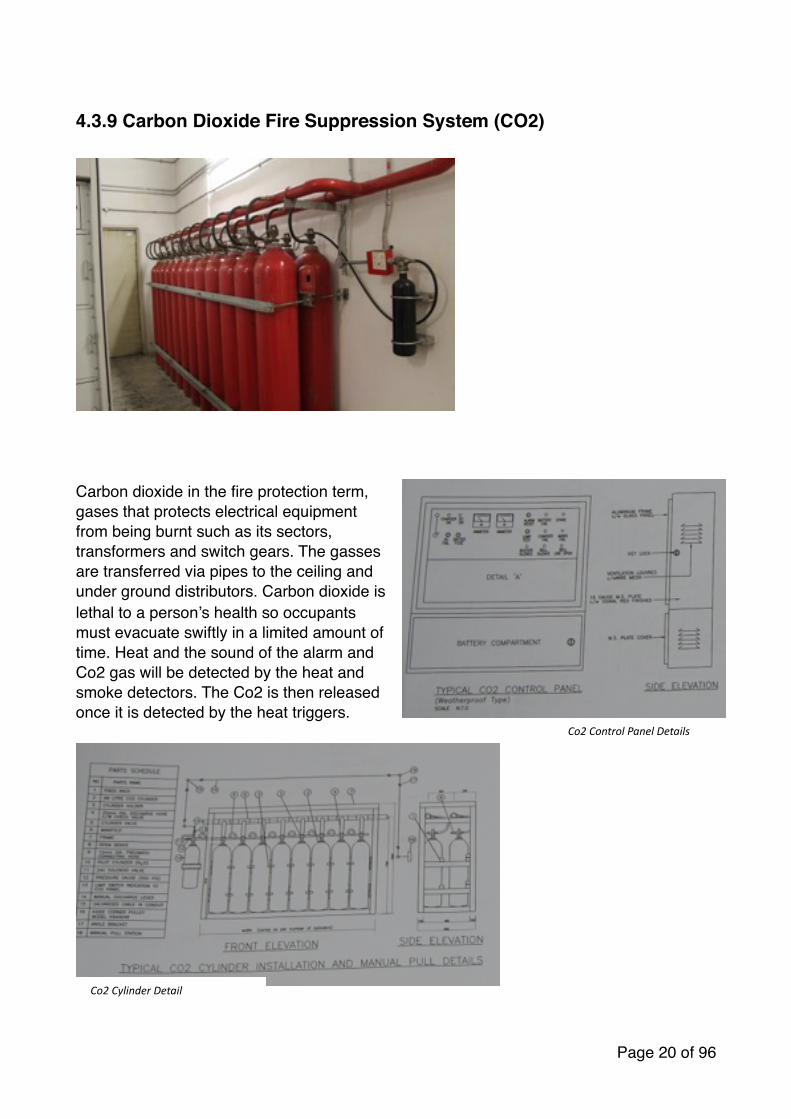
Carbon dioxide in the fire protection term, gases that protects electrical equipment from being burnt such as its sectors, transformers and switch gears. The gasses are transferred via pipes to the ceiling and under ground distributors. Carbon dioxide is lethal to a person’s health so occupants must evacuate swiftly in a limited amount of time. Heat and the sound of the alarm and Co2 gas will be detected by the heat and smoke detectors. The Co2 is then released once it is detected by the heat triggers.
Page � of �20 96
Co2 Control Panel Details
Co2 Cylinder Detail

Page � of �21 96
Co2 for MCC SWITCH ROOM
Co2 for DCP SWITCH ROOM
Co2 for DCP MSB ROOM
4.3.10 External fire Hydrant
�
MFPA (2008) stated that fire hydrant system
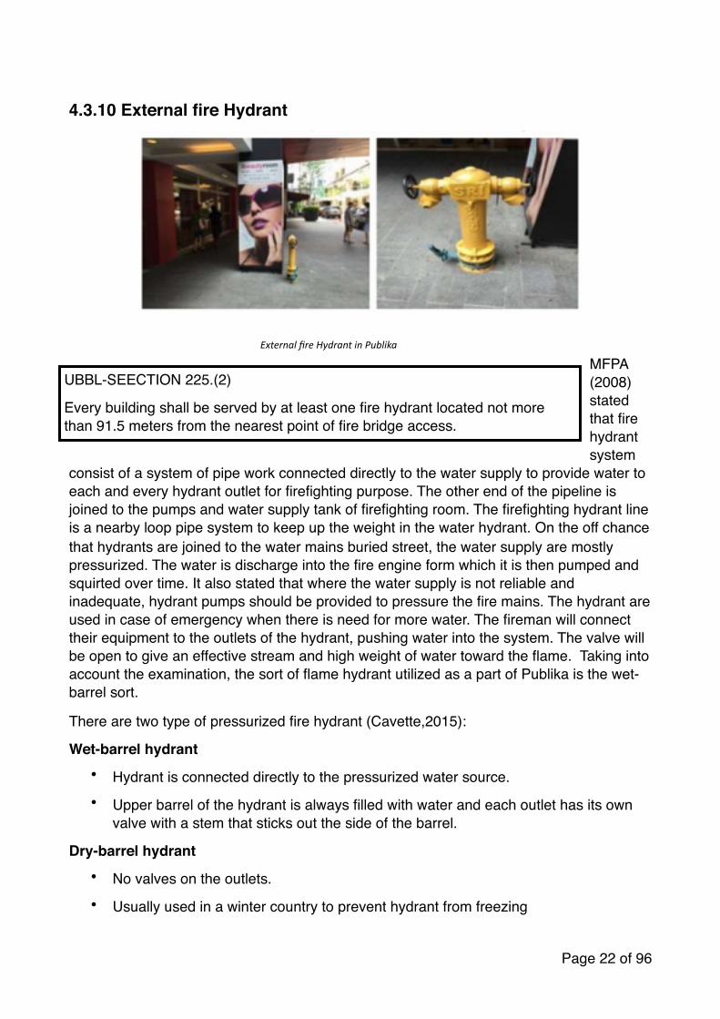
consist of a system of pipe work connected directly to the water supply to provide water to each and every hydrant outlet for firefighting purpose. The other end of the pipeline is joined to the pumps and water supply tank of firefighting room. The firefighting hydrant line is a nearby loop pipe system to keep up the weight in the water hydrant. On the off chance that hydrants are joined to the water mains buried street, the water supply are mostly pressurized. The water is discharge into the fire engine form which it is then pumped and squirted over time. It also stated that where the water supply is not reliable and inadequate, hydrant pumps should be provided to pressure the fire mains. The hydrant are used in case of emergency when there is need for more water. The fireman will connect their equipment to the outlets of the hydrant, pushing water into the system. The valve will be open to give an effective stream and high weight of water toward the flame. Taking into account the examination, the sort of flame hydrant utilized as a part of Publika is the wet-barrel sort.
There are two type of pressurized fire hydrant (Cavette,2015):
Wet-barrel hydrant• Hydrant is connected directly to the pressurized water source.• Upper barrel of the hydrant is always filled with water and each outlet has its own
valve with a stem that sticks out the side of the barrel.
Dry-barrel hydrant• No valves on the outlets.
• Usually used in a winter country to prevent hydrant from freezing
Page � of �22 96
External fire Hydrant in Publika
UBBL-SEECTION 225.(2)
Every building shall be served by at least one fire hydrant located not more than 91.5 meters from the nearest point of fire bridge access.

• Upper section remains dry until the main valve is opened by means of a long stem that extends up through the top of the hydrant.
• Hydrant is separated from the pressurized water source by a main valve in the lower section of the hydrant below ground.
4.3.11 Hose Reel system
� �
Fire hose reels are located to provide a reasonably accessible and controlled supply of water to combat a potential fire risk. The length of a fully extended fire hose is 36 meters with a diameter of 19mm (outside diameter). The hose reel system generally serves as an initial firefighting aid.
Page � of �23 96
Diagram of Hose Reel system
UBBL, SecGon 224(c): Hydraulic Hose Reels
Hose reel shall be located at every 45 meters (depends on the building form). Besides, fire hose reel should be located at the strategic places in buildings, especially nearer to firefighGng access lobbies in order to provide a reasonably accessible and controlled supply of water for fire exGnguishing.
Hose Reel

These appliances are designed to deliver, as a minimum, 0.33L of water per second. A control nozzle attached to the end of the hose enables the operator to control the direction and flow of water to the fire. All fire hose reels come with a unique ball valve shut-off device, a plastic or solid brass hose reel nozzle and mounting bracket
When the hose reel is brought into use, the pressure in the pipe immediately downstream and the pump check valves will drop below the field adjusting the pressure setting of the pressure switch therefore triggering the pump to operate atomically to feed a steady supply of water to discharge through the hose. The fire hose reel outlets should be properly housed in glass fronted cabinet secured under lock and key(dyno,2012)
The hose reel in Publika located in small room with hose reel sticker on the door. it is the same rrom as the fire extinguisher. This is for occupants to use it without exposing them to danger from fire. There are 8 rooms in each floor which means 24 small room for hose reel in total.
Page � of �24 96

4.3.12 Fire Extinguisher
�
A fire extinguisher is an active fire protection device used to extinguish or control little flames in crisis circumstances. Normally, a fire extinguisher comprises of a hand-held barrel shaped weight vessel containing an operators which can be released to extinguish a flame. Portable fire extinguisher are for the most part include in structures having sprinklers and hose reels. The staffs in the building are trained to use it and these appliances should be frequently kept up by the suppliers.
Fire extinguisher are isolated into five classification based on different type of fire. According to Fire Extinguisher Malaysia (2012), the most common type of the extinguisher used in Malaysia are ABC Dry Powder Extinguisher and Carbon Dioxide (CO2) Extinguisher.
�
According to Hall F. (1997), there are several ways to consider in selecting the right type of fire extinguisher, but the most important are as follows:
Page � of �25 96
UBBL-‐SECTION 227
Portable exGnguisher shall be provided in accordance with the relevant codes of pracGce and shall be sired in prominent posiGons on exit routes to be visible from all direcGons and similar exGnguisher in a building shall be of the same method of operaGon.
Carbon dioxide fire ex4nguisher

• It must contain the type of extinguishing agent suitable for the fire it may be require to extinguish.
• It must not be dangerous to the user
• It must be simple to use
• It must be efficient and reliable
There are only a type of fire extinguisher which is carbon dioxide extinguisher. It is more suitable class B, C & E fire which involve flammable liquids and electrical hazards. CO2 is mild to electrical equipment and is ideal for modern office. Chadderton (2000) stated that CO2 Vapour displaces air around the fire and burning ceases. Besides that, he also mentioned that there is minimal cooling effect and there will be chances for the fire to restart it high temperature have become established. It is not sale for wood, paper and cloths.
�
Page � of �26 96
Type of fire

4.4 Passive fire protection system
Passive fire protection systems are those that allow a fire to act upon the system itself, to compartmentalize and contain the fire to save lives and to protect the structure. It is to prevent the passages of hot gasses and flame from passing between fire isolated compartments. Mechanical or electrical activation are not required in this system and the system require no maintenance once they are installed. Passive fire protection begins at the designing and concept stages of any constructions. It is built into the building that will ensure the protection of occupants even in event of the failure of the active protection
According to Nulifire (2014), the overall aim of passive systems is to contain the fire by:
• Use of fire rated partitions and doors to prevent the fire and smoke form moving from one compartment to another
• Delaying the collapse of the building structure
• Delaying the growth on the fire
Page � of �27 96

4.4.1 Fire Rated Door
FIGURE Fire rated door
One of the passive fire protection system we found at the site is fire rated door. Fire rated door, which is also call as fire door is an important fireproof component that designers often have to take concerns while creating the passive fire protection system. Fire door serves as a critical compartment of building entrance or exit in order to prevent the spreading of fire and smoke. 1.5 hours fire-rated door were installed at the egress of fire staircase each floor. The fire doors are well located to allow easy circulations and the escape routes are protected by all these fire doors during the event of fire.
The automatic door closer hinge and devices were installed to fulfil the requirements of By-law Section 164 (1). This device helps to ensure that the fire door is closed at all time to ensure safety.
FIGURE Automatic door closer hinge4.4.2 Separation of Fire Risk Area
Page � of �28 96
UBBL - SECTION 162.(1)• Fire doors of the appropriate FRP shall be
provided• Openings in compartment walls and separating
walls shall be protected by a fire door having a FRP in accordance with the requirements for that wall specified in the Ninth Schedule to these By-laws
UBBL-SECTION 164.(1)• All fire doors shall be fitted with automatic door
closers to the hydraulically spring operated type in the case of the swing doors of wire rope and weight type in the case of sliding door

According to the law and regulations stated above in By-laws, designers must consider about the separations of fire risk area, which should be involved in the spatial planning of the building to slow down the spreading of fire as much as possible.
Page � of �29 96
UBBL - SECTION 139
The following area uses shall be separated from the other areas of occupancy in which they are located by fire resisting construction of elements of structure of a FRP to be determined by local authority based on the degree of hazard :
• Laundries• Storage area of materials in quantities deemed hazardous • Liquefied petroleum gas storage areas • Linen rooms• Boiler rooms and associated duels storage area• Repairs shops involving hazardous processes and materials • Transformer rooms and substations• Flammable liquid stores

4.4.3 Emergency Exit Signage Emergency exit signage
There are neon green Exit signs above the fire escape doors, the signage indicates the way to safety outdoor area during a fire event. Moreover, the emergency lights are also installed within it to give some light if the main electrical supply has been cut off, therefore it is lit 24/7 for emergencies. This device is very effective as it helps to reduce confusion by providing a clear direction of the escape route. In Malaysia, the exit signage is written in Bahasa Melayu, which is “KELUAR” in block letters to be visible enough. This sign is located on top of the fire escape doors, a specific position with no surrounding disturbance.
Page � of �30 96
SECTION 172. • Storey exits and access to such exits shall be marked by readily visible signs and shall
not be obscured by any decorations, furnishing or other equipment• A sign reading “KELUAR” with an arrow indicating the direction shall be placed in every
location where the direction of travel to reach the nearest exit is not immediately apparent
• Every exit sign shall have the word “KELUAR” in plainly legible letters not less then 150mm high with the principal strokes of the letters not less than 18mm wide. The lettering shall be in red against a black background.
• All exist signs shall be illuminated continuously during periods of occupancy

4.4.5 Fire Emergency Staircase
Fire emergency staircase allow the occupants in the building to escape to a safer area or assembly point when there is fire event happening. Following the law, buildings should not have separate exit path in different direction to deny confusion to occupants while escaping.a) Stair Type
Page � of �31 96
UBBL SECTION 168.• The required width of a staircase shall be maintained throughout its length including at
landings. • Except as provided for in by law 194 every upper floor shall have means of access via
at least two separate staircases.• The required width of staircase shall be clear width between walls but handrails may be
permitted to encroach on this width to a maximum of 7.5 millimetres.• Tiles on staircase-risers maximum 180mm and thread minimum 255mm.
UBBL SECTION 169.• No exit ruote may reduce in width along its path of travel from the storey exit to the final
exit.
UBBL SECTION 178.• In buildings classified as institutional or places of assembly, exits to a streets or large
open space, together with staircases, corridors and passages leading to such exits shall be located, separated or protected as to avoid any undue danger to the occupants of the place during a fire event.

The fire resistant escape stairs found on site were made of reinforced concrete stairs enclosed with concrete walls that are only assessable through self closing fire doors. This type of staircase allows a huge amount of human capacity within the stair case lobby, which provides a smooth flow of a large number of occupants during a fire event.
b) Material used
The type of building material used to construct the fire resistant escape stairs is re-enforced concrete. There are many important characteristics using it to construct the fire resistant escape stairs such as : 1) Strength: concrete gains strength over time, therefore it provides strength and stability
to the stairs in the building to overcome any unexpected fire or natural disasters. It is able to withstand massive weight, which can sustain a lot of occupants’ weight while evacuating the building in a rush
2) Fire resistant : concrete is resistant to fire and heat and prevents the spreading of fire throughout the building while withstanding the massive heat from the fire at the mean time
3) Thermal mass : concrete slows down the heat from moving through the building reducing thermal heat gain and changing of temperature within the small area of fire escape lobby. This can prevent the overheating of an enclosed area, which may cause breathing difficulties for occupants.
Fire
emergency staircase escape plan
Page � of �32 96

4.5 Conclusion for Fire Protection
In conclusion, neither active nor passive fire protection system plays an
important role to protect a building when a fire breakdown. The firefighting system in Publlika complies with the UBBL by-Laws and is very systematic as
the entire system is controlled by a control panel. Having a single main controller can prevent the cause of false alarm in the building that will disturb
the occupants. Public also updates their appliances following the requirements of Bomba and every core of the building is filled with the fire
appliances for the safety of the occupants. At last, the overall firefighting system in the building has a proper and good appliances used for various
function of the spaces in the building to ensure the safety of occupants.
Page � of �33 96

5.0 Mechanical Transportation System
5.1 Introduction
This research includes the studies the types of mechanical transportation system used in Shopping Complex.
5.2 Literature Review
Mechanical Transportation System can be referring as a movable machines/system that can hoist or haul passengers and objects from one point to another either in vertical or horizontal motion. Buildings which exceeded more than one floor will have stairs that connect ground floor to upper floor. Introduce mechanical transportation system can reducing the time and physical energy of one occupant when travelling in the building. In addition, the transportation systems also make ease of the senior citizen or disable people to move around the building. Following are the permanent mechanical transportation system usually used in buildings:
1. Elevator
Elevator, which also known as lift, is a vertical transport that efficiently carry people and objects between floors. Elevators run either vertical or inclined to the vertical by less than 15 degree. Every elevator is different from another so the feature and operation will be varies. According to the UBBL clause 124, a lift shall be provided to non-residential building which exceeds 4 storey above or below main entrance. The number of units of elevator will be determining by the population, function of the building and the height of the building.
i) Type of elevatora. Gear and Gearless Traction Elevators with Machine Room
i. Gear traction elevators have a gearbox attach to the motor, which drives the wheels that move the ropes. Geared traction elevators are middle of the road in terms of initial cost, ongoing maintenance costs, and energy consumption.
ii. Gearless traction elevators have the wheel attached directly to the motor. It have a high initial cost, medium ongoing maintenance costs, and use energy a bit more efficiently than geared traction elevators.
b. Hydraulic Elevatori. Supported by a piston at the bottom of the elevator that pushes the
elevator up as the electric motor forces oil or another hydraulic fluid into the piston.
ii. Have a low initial cost and its ongoing maintenance costs are lower compared to the other elevator types.
iii. Use more energy than other types of elevators because the electric motor works against gravity as it forces hydraulic fluid into the piston.
iv. A major drawback of hydraulic elevators is that the hydraulic fluid can sometimes leak, which can cause a serious environmental hazard.
c. Machine-Room-Less (MRL) Elevator
Page � of �34 96

i. Traction elevators that do not have a dedicated machine room above the elevator shaft.
ii. The machine sits in the override space and is accessed from the top of the elevator cab when maintenance or repairs required.
iii. They are energy efficient, require less space, and their operation and reliability are on par with gear-less traction elevators.
2. Escalator
An escalator is a moving staircase which acts as a transport device provides people to move between floors of a building. It can continuously convey to move large number of people efficiently therefore reversible to suit the main flow of traffic during peak hours. It is powered by constant-speed alternating current motors and move at approximately 0.30-0.61m per second.
a. Standard Elevator Types:
i. Parallel Escalator
ii. Crisscross Escalator
Page � of �35 96
Figure 5.1.3: Machine-Room-Less Elevator
Figure 5.1.2: Hydraulic Elevator
Figure 5.1.1: Gear/Gearless Traction Elevator

� �
�
b. Travelators/ Moving Walkway
Travelator is a slow moving conveyor mechanism that transports people across a horizontal or inclined plane over a distance. Travelator can be used by standing or walking on them and are usually install in pair.
a. Inclined Travelator
Page � of �36 96
Figure 5.1.5: Escalator in one direction of travel (Continuous)
Figure 5.1.4: Escalator in one direction
Figure 5.1.7: Flat Step Configuration
Figure 5.1.8: Flat Step Configuration (Used typically
for rises create than 7620mm)
Figure 5.1.6: Escalators for both directions of travel
Figure 5.1.9: Criss-cross Arrangement

� �
b. Horizontal Travelator
�
�
Page � of �37 96
Figure 5.1.10: Inclined moving walkways in parallel
Figure 5.1.11: Criss-cross arrangement
Figure 5.1.12: Horizontal Moving Walkway
Figure 5.1.13: Ramped horizontal moving walkways
5.3 Case Study
A) Elevator
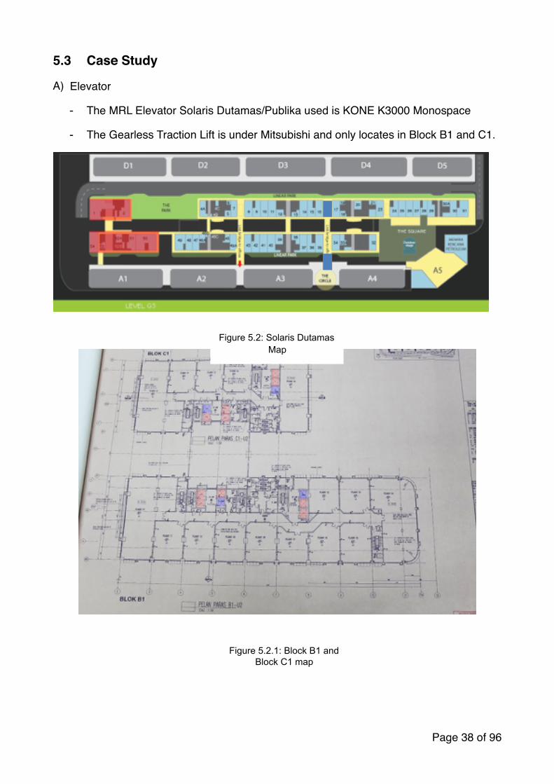
- The MRL Elevator Solaris Dutamas/Publika used is KONE K3000 Monospace
- The Gearless Traction Lift is under Mitsubishi and only locates in Block B1 and C1.
�
�
Page � of �38 96
Figure 5.2: Solaris Dutamas Map
Figure 5.2.1: Block B1 and Block C1 map

Schematic for gearless traction elevator:
�
Page � of �39 96
Figure 5.2.2: Gearless Traction Elevator

Schematic for MRL Elevator
Page � of �40 96
Figure 5.2.3: MRL Elevator

Elevator Shaft
�
Page � of �41 96

Elevator Component Details:
�
The elevator car function as carrying passengers and loads from floors to floors and the car sling function as carrying the elevator car. Car sling is a metal framework connected to the means of suspension.
Page � of �42 96

Car Sling
�
Car sling is the load carrier element in the elevator car as its function of isolating vibrations due to the movement of the lift. Car sling main components:
a) Upper Transom
- The upper transom is the suspension element. It is designed also to mount sliding or roller guide shoes. Braking system catch clamps are mounted in upper transom also.
b) Lower Transom
Page � of �43 96
Figure 5.2.6: Car Sling Component
Figure 5.2.7: Upper Transom

�
- Lower transom is the carrier of car flooring through an exactly arranged pressure springs mounted in the lower isolation subassembly. Safety gear catch clamps are also mounted in the lower transom.
Page � of �44 96
Figure 5.2.8: Lower Transom

Elevator Car
The standard elevator car can be classified according to the number of entrances and their location as follow:
a. Normal Cabin
b. Open through Cabin
c. Diagonal Cabin
�
Page � of �45 96
Figure 5.2.9: Elevator Car Component Details

�
In order to prevent overloading, the space of the elevator is design to limited and related to the rated load of the elevator. The number of the passenger should be obtained from the formula:
Number of passengers = rated load ÷ 75 (the average weight of one person)
�
a) Car Floor:
- Shall have sufficient mechanical strength to sustain forces which will be applied during normal operation, safety gear operation and impact of the car to its buffers.
- Floor size is the same size of the car and floor extension defines door opening, location and side portal depth.
Page � of �46 96
Figure 5.2.10: Elevator Car Size according to requirements by the number of people and designs.
Figure 5.2.11: Arrangement of Elevator Car
Figure 5.2.12: Measurement Table
- Can be covered by PVC or marble stone or granite and can be customized according to client requirements.
b) Car Ceiling:
- Designed to be able to support two persons during maintenance operation without permanent deformation
- Prepared also to mount emergency trap door, blower fan and balustrade.
�
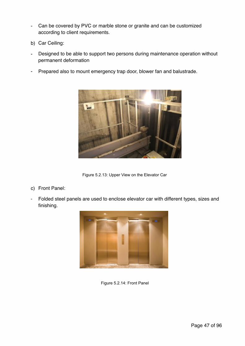
c) Front Panel:
- Folded steel panels are used to enclose elevator car with different types, sizes and finishing.
Page � of �47 96
Figure 5.2.13: Upper View on the Elevator Car
Figure 5.2.14: Front Panel

d) Car Operating Panel
�
Car operating panel (COP) is a panel fixed in the car containing the car operating controls, such as door open and close, emergency button, call register button and floors button.
e) False Ceiling
False ceiling is the main source of lighting in the elevator car. Fluorescent lighting and spot lights are the most common lighting elements that fixed in it.
f) Exhaust fan
▪ Ventilates the air inside the elevator shaft.
Page � of �48 96
Figure 5.2.15: Operating Panel Details
Figure 5.2.16: Exhaust fan in the shaft

g) Guide rails
- Fixed to the hoist way by means of steel brackets
- Steel tracks that run the length of the hoist way and direct the course of travel of an elevator car and elevator counterweights.
- Usually mounted to the sides of the hoist way.
h) Suspension (Hoisting) Ropes (Cables)
- Means for car and counterweight, which are represented by steel wire ropes
- They are used on traction type elevators usually attached to the crosshead.
�
i) Controller
o The main computer to control the function of the elevator whether to stop at specific floors for maintenance or emergency events occur.
Page � of �49 96
Figure 5.2.17: Guide rails and Suspension Ropes
Figure 5.2.18: Controller

Machine Drive System
a) Gearless machine
- It used in high rise applications whereby the drive motor and drive sheave are connected in line on a common shaft, without any mechanical speed reduction unit located between the drive motor and drive sheave.
- Sizes and shapes vary with load, speed and manufacture but the principles and components are the same.
- �
�
Page � of �50 96
Figure 5.2.19: Gearless Traction Details
Figure 5.2.20: EcoDisc Gearless Traction

B) Escalator
a. Otis Escalator
b. Fujitec Travelator
�
Page � of �51 96
Figure 5.3: Escalator Location
Figure 5.3.3: Travelator
Figure 5.3.2: EscalatorFigure 5.3.1: Escalator

The escalator consists of:
1. Landing platforms
2. Truss
3. Tracks
4. Steps
5. Handrail
6. Drive system
7. Auto lubricant System
8. Braking System
9. Safety Devices
10. Electrical & Control Systems
Page � of �52 96Figure 5.3.5: Escalator Details
Figure 5.3.4: Escalator Details

Landing Platform
- These two platforms house the curved sections of the tracks, as well as the gears and motors that drive the stairs. The top platform contains the motor assembly and the main drive gear, while the bottom holds the step return idler sprockets.
- This plate is flush with the finished floor and is either hinged or removable to allow easy access to the machinery below.
- The comb plate is the piece between the stationary floor plate and the moving step where the teeth mesh with matching cleats on the edges of the steps.
- The design is necessary to minimize the gap between the stair and the landing, which helps prevent objects from getting caught in the gap.
- �
Truss
- The escalator truss is the structural frame of the escalator and consists of three major areas:
o The lower section
o Incline section
o Upper section
- Is a hollow metal structure that bridges the lower and upper landings
- Joined together with cross braces across the bottom and just below the top.
Page � of �53 96
Figure 5.3.6: Landing Platform
Figure 5.3.7: Truss Details
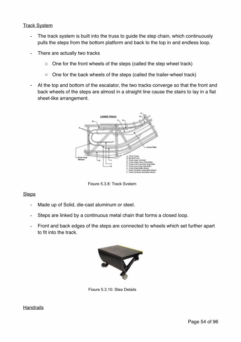
Track System
- The track system is built into the truss to guide the step chain, which continuously pulls the steps from the bottom platform and back to the top in and endless loop.
- There are actually two tracks
o One for the front wheels of the steps (called the step wheel track)
o One for the back wheels of the steps (called the trailer-wheel track)
- At the top and bottom of the escalator, the two tracks converge so that the front and back wheels of the steps are almost in a straight line cause the stairs to lay in a flat sheet-like arrangement.
�
Steps
- Made up of Solid, die-cast aluminum or steel.
- Steps are linked by a continuous metal chain that forms a closed loop.
- Front and back edges of the steps are connected to wheels which set further apart to fit into the track.
�
Handrails
Page � of �54 96
Figure 5.3.8: Track System
Figure 5.3.10: Step Details

- The handrails provides a convenient handhold for passengers who using the escalator.
- Pulled along its track by a chain that is connected to the main drive gear by a series of pulleys.
Balustrade
- Consists of the exterior supporting structure of the escalator and the handrail as well.
- Exterior component that supports the handrails.
�
Page � of �55 96
Figure 5.3.12: Balustrade Details
Figure 5.3.11: Balustrade and Handrails

Drive System
An escalator drive system includes the following components:
- Drive machine and gear reducer
- The step drive system
- The handrail drive system
The drive machine used to drive the pinion gear or the main drive chain may directly or indirectly drive the handrail drive system.
Drive Machine
The drive machine and the gear reducer provide the torque to drive the step band at a constant speed.
▪ The drive machine motor is typically a three-phase AC direct-on-line flange mounted unit.
▪ Is either directly or flexibly coupled to the reduction gear.
▪ The motor is protected by thermal and elector-magnetic overload devices as well as thermistors in the motor winding.
The Step Drive System
- Step motion is achieved by a direct step assembly connection to the step chains
- Two-step chains; one for each side are directly coupled to the main drive axle, the bull gear shaft, through the step chain sprockets.
- Main drive axle is driven by the motor and reducer assembly.
- On both ends of the main drive axle transfer power to the step drive system.
Page � of �56 96
Figure 5.3.13: Drive Machine
Figure 5.3.14: Step Drive System

Handrail Drive System
The handrail drive moves th handrail along the handrail tracking system through traction on the V-shaped handrail underside. The handrail drives consists of the following:
1. The handrail drive and idler sheaves
2. Handrail drive sprockets
3. Handrail drive chains
4. Handrail take-up devices
5. The handrail support rollers.
Safety Devices
- An emergency stop button is provided at both the upper and lower balustrade of the escalator.
- This button allows anyone to stop the escalator immediately in the event of an emergency.
- Can be restarted after releasing the button by using the normal start-up procedure.
Page � of �57 96
Figure 5.3.15: Handrail Drive System
Figure 5.3.16: Emergency Button

5.4 UBBL Requirements
According to UBBL 1984
a. Section 124
For all non-residential buildings more than 4-storeys above or below the main access level at least one lift shall be provided
b. Section 151-155
1. The fire mode of operation shall be initiated by a signal from the fire alarm panel which may be activated automatically by one of the alarm devices in the building or manually.
2. If main power is available all lifts shall return in sequence directly to the designated floor, commencing with the fire lifts, without answering any car or landing calls, overriding the emergency stop button inside the car, but not any other emergency or safety devices and park with door open.
3. 3. The fire lifts shall be available for use by the fire brigade on operation of the fireman’s switch.
4. Under this mode of operation, the fire lifts shall only operate in response to car calls but not to landing calls in a mode of operation in accordance with by law 154
5. In the event of mains power failure, all lifts shall return in sequence directly to the designated floor and operate under emergency power as described under paragraph 2-4.
6. All lift lobbies shall be provided with smoke detectors.
c. Section 243
1. In a building where the top occupied floor is over 18.5 meters above the fire appliance access level fire lifts shall be provide.
2. The fire lifts shall be located within a separate protected shaft if it opens into a separate lobby.
3. Fire lifts shall be provided at the rate of one lift in every group of the fifts which discharge into same protected enclosure or smoke lobby containing the rising main, provided that the fire lifts are not located more than 61 meters travek distance fri the furthermost point of the floor.
Page � of �58 96

5.5 Conclusion
The elevators in Solaris Dutamas / Publika have met all the requirements stated in the UBBL. All the elevators are strategically located next to the exits at the ground floor so that passengers can leave the building and the lift conveniently during fire emergencies. This is to ensure the elevators achieve the requirements of UBBL Section 154. Besides, they also achieved eco-friendly by using Ecodisc system from KONE to reduce the pollution to the surrounding.
There will be a fire lift locates next to each passenger lift. Therefore, all the fire lifts fulfilled the requirement of having smoke detectors at the life lobbies. The fire lifts, which are set in every group of elevators, fulfilled the requirement of UBBL Section 243.
In conclusion, there are still potential dangers to passengers when using the mechanical transportation although it achieves the UBBL. Passengers have to be careful when using the mechanical transportation to prevent getting hurt by events such as equipment malfunctions and accident cause by unintended consequences.
Page � of �59 96

6.0 Air Conditioning and Mechanical System6.1 Introduction
AC, also referred as Air Conditioning serves the main purpose of achieving thermal comfort and maintaining the indoor air quality within a building. In short, it is described as the technology of indoor and vehicular environmental comfort. It achieves its goal by replacing the indoor air with fresh air as well as changing the air properties within the building by controlling the temperature, humidity to a more suitable and comfortable environment.
6.2 Literature Review
6.2.1 Air Conditioning System
Air Conditioning is the process of altering the properties of air primarily the temperature and humidity through mechanical means. It can also be referred as the total control of temperature, air humidity and air cleanliness.
Every building that uses air conditioner has its own air conditioning system that can converts the humidity and temperature in a building as well air ducts that controls the flow of the air within the building. An air conditioner works similarly to a refrigerator, using a remarkable physics law known as phase conversion which explain when a liquid is converted in gas, it absorbs heat. With this, the air conditioner goes through a cycle known as the refrigerant cycle.
Different air conditioning system have different advantages over others and are chosen depending on requirements of the building such as size, design, environmental friendly etc. A typical system of an air conditioner usually consists compressor, condenser and evaporator but that’s not always the case depending on the system used.
� �
Refrigerant Cycle Type of HVAC system
Page � of �60 96

6.3 Case Study
6.3.1 Air Conditioner System
6.3.1.1 Introduction
This research paper covers the air conditioning system adopted by the chosen building, Publika which is an upscale neighbourhood shopping mall located in Solaris Dutamas, Sri Hartamas. Being a rather large mall, the air conditioning systems used in Publika are distributed using central air conditioning system with AHU. The central air conditioning system comes from the fact that the system conditions the entire air conditioner system from one large area. This system circulate cool air through a system of supply and return ducts.
This system is efficient and more effective in larger space that need high cooling loads within the shopping mall. Cool air is distributed around using a series of duct system which is also connect to the Fan Coil Units (FCU) and Air Handling Unit (AHU) that is located in the mall hidden from the public.
�
6.3.1.2 District Cooling System
The cooling systems here not only supply to Publika but to the whole Solaris Dutamis. Unlike typical shopping mall system, Solaris Dutamas uses a district cooling system as the system is able to meet the cooling demands of dozen of buildings. District Cooling System consist of a central plant chills water that distribute chilled water to the Air Handling Units (AHU). The warmer water is returned to the central plant to bre re-chilled.
Page � of �61 96

Solaris Dutamas is consider a smaller district to be using District Cooling System, but nonetheless, it is still the most suitable system for it. Since it is smaller in size, the central plant is located in one of the basement of a building.
6.3.1.3 Water-Cooled Chilled Water System
Publika uses a system known as the water-cooled chilled water system. This air conditioning system uses water to the chiller and then to air handling units to cool the air. The chilled water system isn’t like a typical residential system, it doesn’t use any compressor since it doesn’t use any gas refrigerant. The reasons Publika chose this are:
1. Environmental Friendly. Since it uses water instead of gas refrigerant that release gas such as Chlorofluorocarbon as waste product.
2. The systems fit better with the design of Publika.
3. It is also proven to be safer and no hazard of piping refrigerant all around the building. Since it uses water as a refrigerant which is non- corrosive, have specific heat value, fluid and non-toxic.
4. Maintenance is easier. The maintenance for this system is easier compared to other system since it usually only have to replace the filters and also leaking in this system is only leaking of water instead of dangerous or toxic gas.
5. Energy Saving. The Chiller doesn’t activate until the temperature in the water reservoir reaches a certain temperature which helps provide significant energy saving.
How Water-Cooled Chilled Water System Works
The main components that make up the Water-Cooled Chilled Water System are the Cooling Tower, Chiller, Ice Tank and FCU/AHU. The Chiller will be that main component where the heat exchange occurs. The water will leave the chiller at 7°C and circulate through the building to Air Handling Units and Fan Coil Units. The water cooled the space and will return at about 13°C to a reservoir/ice tank. When the water in the reservoir reaches a certain temperature, the water will be send to the chiller again and the process will be repeated. The unwanted heat receive from the chiller during heat exchange is disposed to the cooling tower through pipes. Publika have 4 cooling towers which is located at one of the roof top of the building as cooling towers are required to be placed in area with good ventilation and away from public. The cooling tower would remove the heat from the water and expelled it to the outside with evaporation. The water entering the cooling tower are about 35°C and will drop to 29°C when leaving the cooling tower. The enter will then re-enter the chiller to collect waste heat energy again. This process will also repeated.
Page � of �62 96

�
�
Diagrams Showing How The System Works
6.3.1.4 Components of Air Conditioning System
a. Chiller
�
A chiller is a machine that cools the water in the chilled water system. It cools the water by removing the heat from the water and transfer it to another water cycle that functions to expel the heat to the outside. So basically, the chiller is involved in two process, one that cools the water and send it to the and send it to the FCU/AHU (Process 2) and another
Page � of �63 96

that collects the heat from process 2 using the condenser in the chiller and delivers it to the cooling tower to be expelled to the atmosphere(Process 1).
Water-Cooled Chiller vs Air-Cooled Chiller
Air-Cooled chiller rejects the heat through the fans to the atmosphere while a Water-Cooled Chiller rejects the heat rejects the heat through a cooling tower to the atmosphere.
b. Cooling Tower
� �
Publika Cooling Tower (model: Evapco At228-0824) Cooling Function Diagram
A cooling tower is used to dispose unwanted heat from a chiller. Warm water from the heat source is pumped to the water distribution system at the top of the tower. The water is distributed over the wet deck fill by means of large orifice nozzles. Simultaneously, air is drawn in through the air inlet louvers at the base of the tower and travels upward through the wet deck fill opposite the water flow. A small portion of the water is evaporated which removes the heat from the remaining water. The warm moist air is drawn to the top of the cooling tower by the fan and discharged to the atmosphere. The cooled water drains to the basin at the bottom of the tower and is returned to the heat source.
Page � of �64 96

c. Reservoir / Ice Tank
�
Page � of �65 96

The reservoir is where cold water is stored before deliver to AHU/FCU. In Cooled Water Chilled Water System, the chillers are not connected directly to the AHU/FCU, It is connected to a reservoir/Ice tank and only activates when the water in the reservoir rises to a certain degree. The water from the reservoir would be send to the chiller and be cooled down to approximately 7°C and send back to the water reservoir. The water in the reservoir will then be delivered to AHU/FCU to deliver cool air to the building. The water would cooled the space and return to the reservoir at about 13°C.
Air Handling Unit (AHU)
Air handling units (AHUs) also known as Air handlers are used to supply and circulate air around a building, or to extract stale air as part of a building’s heating, ventilating and air conditioning (HVAC) system. Total of 10 AHUs located in Publika Solaris Dutamas building. It is used for big area in public like Publika Mall.
Figure Location os AHU Rooms in Publika
Essentially, an Air Handling Unit system comprises a large insulated metal box that contains a fan, heating and/or cooling elements, filters, sound attenuators and dampers. In most cases, the AHU is connected to air distribution ductwork; alternatively, the AHU can be open to the space it serves.
Supply air passing through the AHU is filtered and is either heated or cooled, depending on specified duty and the ambient weather conditions. In some buildings, Air Handling Units are used only to supply fresh air for ventilation and extract stale air.
For heating or cooling, AHUs may be connected to central plant such as boilers or chillers, receiving hot or chilled water for heat exchange with the incoming air. Alternatively, heating or cooling may be provided by electric heating elements or direct expansion refrigeration units built into the air handler.
Figure Air Handling Room in Publika
Page � of �66 96

�
Page � of �67 96
Return DuctChilled Water In/Out
Supply Duct
Control Panel
Air Handling Unit

When AHU systems are used to extract stale air from the building, a controlled proportion of this air may be recirculated to avoid having to condition all supplied air. AHUs can also incorporate heat recovery mechanisms to extract heat from the air being expelled and use it to heat incoming supply air.
Air Handling Units vary considerably in size, capacity and complexity, depending on the job they are designed to perform.
6.4 Air Handling Unit Components
6.4.1 Air Filter
Air filtration is almost always present in order to provide clean dust-free air to the building occupants. Filtration is typically placed first in the AHU in order to keep all the downstream components clean.
Figure Air Filter of AHU in Publika
6.4.2 Cooling Coils
Air handlers may need to provide heating, cooling, or both to change the supply air temperature, and humidity level depending on the location and the application. Such conditioning is provided by heat exchanger coil(s) within the air handling unit air stream, such coils may be direct or indirect in relation to the medium providing the heating or cooling effect.
Figure Example of Cooling Coils
Page � of �68 96

6.4.3 Humidifier
Humidification is often necessary in colder climates where continuous heating will make the air drier, resulting in uncomfortable air quality and increased static electricity. Evaporative type is used on Publika to dry air blown over a reservoir will evaporate some of the water. The rate of evaporation can be increased by spraying the water onto baffles in the air stream.
Figure Humidifier of AHU
Figure Diagram of Humidifier Process
Page � of �69 96
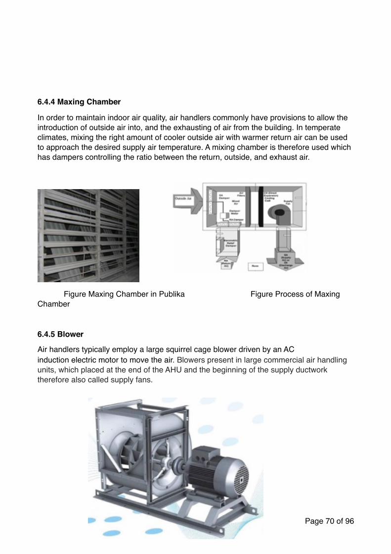
6.4.4 Maxing Chamber
In order to maintain indoor air quality, air handlers commonly have provisions to allow the introduction of outside air into, and the exhausting of air from the building. In temperate climates, mixing the right amount of cooler outside air with warmer return air can be used to approach the desired supply air temperature. A mixing chamber is therefore used which has dampers controlling the ratio between the return, outside, and exhaust air.
Figure Maxing Chamber in Publika Figure Process of Maxing Chamber
6.4.5 Blower
Air handlers typically employ a large squirrel cage blower driven by an AC induction electric motor to move the air. Blowers present in large commercial air handling units, which placed at the end of the AHU and the beginning of the supply ductwork therefore also called supply fans.
Page � of �70 96

6.4.6 Heat Recovery Device
A heat recovery device heat exchanger of many types, may be fitted to the air handler between supply and extract airstreams for energy savings and increasing capacity.
Figure Example of Mechanical Blower
6.4.7 Vibration Isolators
The blowers in an air handler can create substantial vibration and the large area of the duct system would transmit this noise and vibration to the occupants of the building. To avoid this, vibration isolators (flexible sections) are normally inserted into the duct immediately before and after the air handler and often also between the fan compartment and the rest of the AHU. The rubberized canvas-like material of these sections allows the air handler components to vibrate without transmitting this motion to the attached ducts.
Page � of �71 96

6.5 Fan Coil Unit (FCU)
FCU is a simple device consisting of a heating or cooling coil and fan. It is part of an HVAC system found in residential, commercial, and industrial buildings. Typically a fan coil unit is not connected to ductwork, and is used to control the temperature in the space where it is installed, or serve multiple spaces. It is controlled either by a manual on/off switch or by thermostat.
Figure Fan Coil Unit in Publika
Publika is using Trane as their main cassette-type minisplit air conditioners. Designed for recessed ceiling installation and provide years of comfortable, convenient cooling, with minimal service required.
Features• Fit all needs• Available in 50 Hz cooling
4-Way Direction Air Flow
This multiflow system feature four different settings of the discharge outlets, offering many benefits:
- Provides wide vertical air distribution for better comfortable while cooling the entire room in a short period of time.- Enhances down-flow performance and enables wide-range air-conditioning for medium discharge.- Enables adjustment of the airflow direction to reduce air resistance.- Quite operation: high efficiency with low noise levels.
Page � of �72 96

Figure Orthographic of Trane Cassette-type Air Conditioners
Trane Air Conditioners are designed and constructed to provide long life and trouble free system and the automatic temperature adjustment for more comfortable sleeping conditions and energy savings.
Page � of �73 96

6.5.1 Jet Diffusers
Publika is using ASU CK jet diffusers because of it’s made out of a fixed outer frame and adjustable concentric rings, which specially designed for high volume and long throw applications. The concentric rings can be adjusted 45 degree upward and downward or leftward and rightward depending on the installation position to control the direction of airflow. CK jet diffusers are suitable to be installed on exposed ductwork or surface mounted in stadium, factory, theatre and etc.
Features
• Economical• Long throw capability• High air flow capability• Suitable for exposed ductwork or surface mounted• Suitable for ceiling or wall installation• Air flow direction is adjustable up to 45 degree upward and downward or leftward
and rightward
Page � of �74 96

Figure Jet Diffuser in Publika
Page � of �75 96

6.5.3 Return Air Grilles
A return air grille is a connection to ductwork that allows air to return to a heating and cooling system. Publika is using C Curve Blade Return Air Grille as their main return air grille. Return air openings are typically covered with grillwork that serves a number of different functions. A variety of companies make coverings for these openings that people can use to replace existing covers or can install with a brand new system. These products are available through catalogs, hardware stores, and contractors, as well as manufacturers of ducting systems.
Figure C Curve Blade Return Air Grille in Publika
Features
• The shape of the curved blade is approximately one eighth of the circumference of a circle.
• Suitable to install on wall for return air application.• The grille will come in more sections for blade length that is more than 600mm.• Approximately 48% free area.
Figure RC Construction Illustrations of Return Air Grille
Page � of �76 96

7.1 Introduction (Mechanical Ventilation System)Ventilation (the V in HVAC) is the process of intentional introduction of outside air into a space or replacing air in any space to provide high indoor air quality. To achieve the desired indoor psychrometric condition, ventilation is used to dilute and displace indoor pollutant, creating thermal comfort and dehumidification in the building as it involves temperature control, oxygen replenishment, and removal of moisture, odours, smoke, heat, dust, airborne bacteria, and carbon dioxide. This process also removes unpleasant smells and excessive moisture by introducing outside air to keep the interior building air circulating, preventing stagnation of the interior air. The methods of ventilation in a building is divided into two types which is the mechanical ventilation and natural ventilation.
�Figure 7.1.1 Diagram showing difference between natural and mechanical ventilation in a house.
1. Natural Ventilation
The natural ventilation is the ventilation of a building with outside air without using fans or other mechanical systems. There are three types of natural ventilation occurring in buildings, such as wind driven ventilation, pressure-driven flows and stack effect.
Natural ventilation can be achieved by using windows, louvers, or trickle vents when spaces are small and the architecture permits. In more complex schemes, warm air is allowed to rise and flow out high building openings to the outside, causing cool outside air to be drawn into low building openings, this process is called the stack effect. The wind driven ventilation relies upon force of the prevailing wind to pull and push air through the enclosed space as well as through breaches in the building’s envelope.
The benefit of using natural ventilation over mechanical ventilation is it consumes lesser energy as it mainly comes at the stage where building were designed to have openings that provides natural ventilation whereas mechanical requires external components to generate air into the space.
Page � of �77 96

�Figure 7.1.2 Diagram showing natural ventilation strategies.
The amount of air exchanging in a space (CFM) must be determined by using the information pertaining to the suggested air changes for proper ventilation from the local building codes. The ranges specified will adequately ventilate the corresponding areas in most cases however some extreme conditions may require “minutes per change” outside of the specified range. A space or room with the appropriate suggested air changes value will be a space with proper ventilation which gives comfort for the users inside the space.
�Figure 7.1.3 Suggested air changes for proper ventilation chart for different spaces.
Page � of �78 96

7.2 Literature Review Mechanical ventilation is used for applications where natural ventilation is not appropriate such as in warm or humid climates where maintaining thermal comfort solely via natural ventilation may not be possible. Mechanical ventilation is the process of changing air in an enclosed space, where indoor air is withdrawn and replaced by fresh air continuously that is supplied by clean external sources by the uses of mechanical devices such as fans, filters and etc. Mechanical ventilation system are often found in domestic bathrooms and kitchens where the aim is to remove smoke, odours, stale air such as water vapour and etc. by using extractor fans.
The benefits and importance of maintaining a proper mechanical ventilation includes
• Preservation of oxygen content while removing carbon dioxide content at the same time.
• Prevention of heat concentrations from machinery, lightning and people.• Reduces excess condensation.• Dispersal of concentrations of bacteria.• Dilution and disposal of contaminants such as smoke, dust gases and body
odours.• Consistent freshness is provided.
There are two types of mechanical ventilation system, which is spot ventilation, and energy-recovery ventilation system. The spot ventilation system includes supply system, extract system or a combined system.
(a) Supply System
The supply system works by pressurizing the building by using mechanical fans to force outside air into the building while the air leaks out of the building through holes in the shell, bath and range-fan ducts, and intentional vents. By pressurizing the house, these systems discourage the entry of pollutants from outside and prevent back drafting of combustion gases from fireplaces and appliances. The also allow air introduced into the house to be filtered to remove pollen and dust, or to be dehumidified.
The supply system do not temper or remove moisture from the air before it enters the house, so they may lead to a higher heating and cooling cost compared to energy recovery ventilation system.
Page � of �79 96

�Figure 7.2.1 Supply system in a building.
(b) Exhaust System
The exhaust ventilation systems work by depressurizing the building which is extracting indoor air from a house while make-up air infiltrates through leaks in the building shell and through intentional passive vents. Exhaust ventilation system is composed of a single fan that is connected to a centrally located single exhaust point in the house. As exhaust fan draws in outdoor air, it might draw in pollutants along with the fresh air into the house as well, such as radon and moulds from a crawlspace, dust from an attic, fumes from an attached garage and flue gases from a fireplace or fossil fuel-fired water heater and furnace.
�Figure 7.2.2 Exhaust/Extract System in a building.
Page � of �80 96

(c) Combined/Balanced System
A combined/balanced ventilation system pressurizes and depressurizes a house as they introduce and exhaust approximately equal quantities of fresh outside air and polluted inside air. It usually has two fans and two duct systems and it facilitates good distribution of fresh air by placing supply and exhaust vents in appropriate places. It is mostly designed to supply fresh air to bedroom and other common rooms such as living room and study room where people spend the most time and also exhausts air from the rooms where moisture and pollutants are often generated in, such as kitchen and bathrooms. It uses filters to remove dust and pollen from outside air before introducing it into the house. A balanced ventilation system are appropriate for all climates.
�Figure 7.2.3 Combined/Balanced System in a building.
(d) Energy-Recovery Ventilation
The energy recovery ventilation system is the energy recovery process of exchanging the energy contained in normally exhausted building or space air and using it to treat the incoming outdoor ventilation air in residential and commercial HVAC systems. During the warmer seasons, the system pre-cools and dehumidifies while humidifying and pre-heating in the cooler seasons. The benefit of using energy recovery is the ability to meet the ASHRAE ventilation & energy standards, while improving indoor air quality and reducing total HVAC equipment capacity.
Page � of �81 96

�Figure 7.2.4 Diagram showing how Energy-Recovery Ventilation System works.
7.3 Case StudyCombined/Balanced Ventilation System
Being a rather large shopping mall, the Publika Mall uses natural ventilation and a combined ventilation system with both supply and extract system. The Publika Mall uses not only conventional mechanical ventilation components, while uses new and better components which is more efficient and cost saving.
Components involved in Mechanical Ventilation System in Publika Mall.
1. Fan
1a. Propeller Fan
�Figure 7.3.1 Wall mounted propeller fan in the fire protection room.
Page � of �82 96
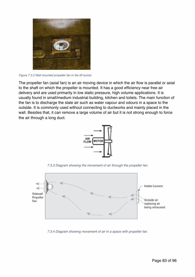
�Figure 7.3.2 Wall mounted propeller fan in the lift tunnel.
The propeller fan (axial fan) is an air moving device in which the air flow is parallel or axial to the shaft on which the propeller is mounted. It has a good efficiency near free air delivery and are used primarily in low static pressure, high volume applications. It is usually found in small/medium industrial building, kitchen and toilets. The main function of the fan is to discharge the stale air such as water vapour and odours in a space to the outside. It is commonly used without connecting to ductworks and mainly placed in the wall. Besides that, it can remove a large volume of air but it is not strong enough to force the air through a long duct.
�7.3.3 Diagram showing the movement of air through the propeller fan.
�7.3.4 Diagram showing movement of air in a space with propeller fan.
Page � of �83 96

1b. Jet Fan System
�
The jet fan is a type of a compressor that increases the pressure of the air flowing through it which can be found mainly in basement or tunnels. The effective use of the piston effect by vehicles and natural wind boosts the ventilation, making the system very cost-effective. The blades of the axial fan forces air to move parallel to the shaft about which the blades rotate, flowing axially in and out linearly. It consists of two to six blades which is lesser than ducted fans. They operate at high specific speed and the number of blades will restrict the flow rate required for its operation. For example, the higher flow rate and low head required, the more blades will be added to restrict it the high flow rate. The fewer blades they has will cause them unable to impose their geometry on the flow, which will make the rotor geometry and the inlet and outlet velocity triangles meaningless.
ASHRAE Standard 90.1 – 2010 PART 3 HVAC PROVISIONS
SecGon 6.4.3.4.4 VenGlaGon Fan Control
Fans with motors > ¾ h.p (0.5kW) shall have automaGc controls complying with secGon 6.4.3.3.1 that are capable of shufng off fans when not required.
ExcepGon: HVAC systems that operate conGnuously.
Figure 7.4.5Jet Fan founded in the basement car park of
ASHRAE Standard 90.1 – 2010 PART 3 HVAC PROVISIONS
SecGon 6.4.3.4.5 Enclosed Parking Garage VenGlaGon
Enclosed parking garage venGlaGon systems shall automaGcally detect contaminant levels and stage fans or modulate fan airflow rates to 50% or less of design capacity provided that acceptable contaminant levels are maintained.
Page � of �84 96

2. Filter
Air cleaning and filtration is an important factor of our indoor environment because cleaning the air filters out what the lungs cannot by removing particles, contaminants, vapours and gases from the air. The filtered and cleaned air then is used in heating, ventilation and air conditioning. Air cleaning and filtration should be taken in account when protecting our building environments.
The air introduced into the space is normally containing a certain amount of different substances inside such as particles, contaminants, vapours, gases, bacteria, smokes and etc. These contents have to be filtered before being introduced into the building as it might be harmful to the user’s health if the content are being breath into the body. Thus, the filter plays a major part to sift the air before directing them into the building. Different kind of filters are used at different places.
2a. Activated carbon filter mesh G4
Group G of filter types is classified as filters for coarse dust particles and it is efficient for particles ≥ 10 μm.
• This type of filter is mainly applied on• Waste air of painting boxes and kitchens• Protection against the pollution of air conditioning and compact instruments• Pre-filters for the filtration classes F7 and F8• Pre-filters and circulation filters for public protection equipment
�Figure 7.3.6 Use of carbon filter mesh on the part of ductwork where air flow through.
Page � of �85 96

�Figure 7.3.7 Use of filter at the end of ductwork.
2b. Activated carbon filter mesh M5
The filter mesh M5 is in group F of filters for fine dust which is Efficient for particals ≥ 1 μm. It mainly separates spore, cement dust, particles creating stain or dust sedimentation and it is mainly used as entering filters for the areas with low demand such as workshops, storages and garage.
�Figure 7.3.8 Filter mesh M5 found outside the eletricity room in the basement car park.
�Figure 7.3.9 Filter mesh M5 found along the ductwork for the release of clean air.
Page � of �86 96

3. Fire Damper
Fire dampers are passive fire protection products used in heating, ventilation, and air conditioning (HVAC) ducts to prevent the spread of fire inside the ductwork through fire-resistance rated walls and floors. Fire/smoke dampers are similar to fire dampers in fire resistance rating, and also prevent the spread of smoke inside the ducts. When a rise in temperature occurs, the fire damper closes, usually activated by a thermal element which melts at temperatures higher than ambient but low enough to indicate the presence of a fire, allowing springs to close the damper blades. Fire dampers can also close following receipt of an electrical signal from a fire alarm system utilising detectors remote from the damper, indicating the sensing of heat or smoke in the building occupied spaces or in the HVAC duct system.
3a. SD-T Smoke Damper
The damper used in Publika mall is different than a conventional damper, which is the SD-T Smoke Damper. These dampers works better as compared to conventional dampers as when the conventional dampers are fully closed, there are still some visible gaps between the blades and the stoppers. SD-T Smoke Damper has incorporated blade seal and angle stopper to seal up the gaps. SD-T has also improved on its jamb seal by using reinforced stainless steel plate, which will not deform or vibrate in high pressure or when the blades are rotating. Hence the air leakage rate has been greatly reduced.
�Figure 7.3.10 Image of SD-T Smoke Damper
Description
The smoke dampers are low leakage damper constructed with triple V-groove blades designed to be used in ducts that penetrate smoke rated barriers. He SD-T may be installed vertically or horizontally of a smoke barrier and is designed for use in systems with airflow in either direction with velocity up to 2000dpm and pressure up to 4”w.g.
Page � of �87 96

�Figure 7.3.11 axonometric view of SD-T Smoke Damper
�Figure 7.3.12 Construction Illustration of SD-T Smoke Damper
�Figure 7.3.13 Comparison diagram of conventional damper and SD-T smoke damper.
Page � of �88 96

�Figure 7.3.14 Sectional drawing showing the installation of SD-T smoke damper.
Material• Frame: Galvanized steel, 1.5mm thickness.• Blade: Galvanized steel, 1.5mm thickness.• Blade Seal: Silicone strip (Fire resistance up to 250’C)• Jamb Seal: Reinforced Stainless steel plate, compression type.• Bearing: Bronze bush pressed into frame.
• Axles: Square steel bar shaft.
Surface Finish
• Mill galvanized
Blade Action• Parallel blade
Blade Dimension Limits• Maximum blade length= 1000mm• Maximum blade width=160mm
�
ASHRAE Standard 90.1 – 2010 PART 3 HVAC PROVISIONS
SecGon 6.4.3.4.2 VenGlaGon Shutoff Damper Controls
All o.a. intake and exhaust systems shall be equipped with motorized dampers that will automaGcally shut when the system or spaces served are not in use.
ExcepGons
Page � of �89 96

4. Grille and Diffuser
4a. Return Air Grilles
A return air grille is connected to the end of a ductwork that allows air to return to a heating and cooling system. Return air openings are covered with grillwork that serves a certain functions. In the ventilation system, the central furnace or air conditioner pushes air out through a system of ducts into the rooms of a structure for temperature control and also pulls air in through return ductwork. The air sucked into the system is heated or cooled as needed and redistributed the desired spaces. They also act as a cover for the ductwork so that people do not look at it, as for aesthetical and safety purpose. It also prevents large objects from entering the ducts that might damage the system.
�Figure 7.3.15 Return air grille found outside ACHU room in the basement car park.
�
Figure 7.3.16 Return Air Grille located on the ceilings of along the corridor.
4b. C Curve Blade Return Air Grille
The air grille used in PUBLIKA mall is called the C curve blade return air grille, which is a one way square return air grille. It is face mounted for easy installation on walls and ceilings. It has a inconspicuous fingertip lever for air volume control.
Page � of �90 96

�Figure 7.3.17 Detail drawing of C curve blade return air grille.
�Figure 7.3.18 Diagram showing air movement going out from the grille.
Materials
• RC-A Extruded aluminium A6063.
• RC-T Galvanized steel.
Surface Finish• Baked white powder coat or natural anodized.
Features• The shape of the curved blade is approximately one eighth of the circumference of
a circle.• Suitable to install on wall for return air application
• The grille will come in more sections for blade length that is more than 600mm.
• Approximately 48% free area.
Accessories• R6 Insect nettings.• D2 Square to round adapter.
Page � of �91 96

5. Pressurisation System
A pressurisation system protects escape routes and fire-fighting shafts against the ingress of smoke. Smoke and fire ventilation is maintained by the pressure within the escape route being higher than that in the adjacent spaces. They provide no protection within the space containing the fire, but contain the smoke and heat so that it cannot enter the main building escape routes.
Components in a pressurisation system that creates a positive pressure difference which prevents lobbies and staircases from filling up with smoke:
• Air Supply (where air is introduced into the area that is to be protected)• Pressure Relief (to avoid overpressure when doors are closed)
• Air Release (air and smoke is released form the adjoining fire area)
The System Comprises:
• Inlet Fans for introducing air into the designated area. The run and standby fans and control equipment should be housed in a separate plant room or outdoors and the inlet should be protected from smoke. Dual inlets with automatic smoke dampers are required for high level inlet.
• Ductwork and Outlet Grilles, to provide distribution of air exactly where it is needed.• Pressure relief dampers, to release excess air in the closed door condition from the
stair area. This should be ducted to discharge directly to atmosphere independent of the wind direction. Damper blades are set to start opening at 50 Pa pressure differential.
• Automatic air release to prevent unwanted pressure build up in the adjacent spaces. This may be automatic vents, natural shafts or mechanical extract systems.
• The control system should operate automatically from the smoke detection system with a manual on/off switch also provided within either the pressurisation plant room, near the building entrance (to suit fire service), or within the central building services control room.
Page � of �92 96

Each of the pressurisation system in publika is designed specifically for the type of space and based on the requirements.
�7.3.19 Staircase Pressurization System at staircase 1
�
7.3.20 Staircase Pressurization System at staircase 2
Page � of �93 96

�7.3.21 Lift Lobby Pressurization System
�
ASHRAE Standard 90.1 – 2010 PART 3 HVAC PROVISIONS
SecGon 6.4.3.4.5 Enclosed Parking Garage VenGlaGon
Enclosed parking garage venGlaGon systems shall automaGcally detect contaminant levels and stage fans or modulate fan airflow rates to 50% or less of design capacity provided that acceptable contaminant levels are maintained.
Page � of �94 96

7.4 Conclusion for Mechanical VentilationIn conclusion, the use of combined/balanced system is the best option for a rather large mall like Publika. The usage of different mechanical ventilation components at appropriate places has created a space which is thermally comfortable. Besides that, an appropriate level of humidity and air freshness which bought by the replenishment of oxygen and exchanging of carbon dioxide has allowed the visitors feel comfortable in the mall. More than that, the ventilation system does not cover only for the upper levels of the mall, the lower levels which is the basement car park consists of the Jet Fan system that increases the ventilation level for the comfort of the users inside the car park.
The ventilation system in Publika is not only for the comfort of visitors, but also the safety of visitors by the use of fire dampers and pressurization systems which is specifically designed. Instead of conventional fire dampers, Publika uses SD-T Smoke Damper which is more efficient and cost saving. The different types of filter being used in different places are taken in consideration to ensure the appropriate usage of filter at places, thus the correct particles will be filtered and may not harm the people inside. The pressurization system are specially designed for each of the spaces such as staircases and lift lobby.
The mechanical ventilation system in Publika compiles with the regulations set by the bodies such as the UBBL and ASHRAE standards. This has ensure that the right and correct usage of components in the building.
Page � of �95 96

Reference
Fire Protection1. https://www.mdkl.gov.my/documents/10124/305128ab-f7f0-4547-9124-27a3cee67bdc
2. http://www.understandconstruction.com/understand-fire-fighting-systems.html
3. http://www.mfs.sa.gov.au/site/community_safety/commercial/building_fire_safety/fire_fighting_systems_and_equipment_in_buildings.jsp
4. https://www.eagle.org/eagleExternalPortalWEB/ShowProperty/BEA%20Repository/Rules&Guides/Current/141_FireFightingSystems/Pub141_FireFighting
5. http://gcc.glendale.edu/fire/Documents/ClassMaterials/Ch36.FireDetection&SuppressionSystem.PPHandout.pdf
Air Conditioning1. All About Air Conditioning. (n.d.). Retrieved November 23, 2015, from https://
www.ashrae.org/resources--publications/free-resources/top-ten-things-about-air-conditioning
2. Bibliography. (n.d.). HVAC Engineer's Handbook, 224-227.
3. The Load Sub-System - Air-Conditioning Equipment. (n.d.). Solar-Assisted Air-Conditioning in Buildings, 7-14.
4. http://www.hvac.com
Mechanical Ventilation and Transportation1. http://www.solutionsforair.com/dayton_content/pdfs/ventilationfundamentals.pdf
2. http://www.ksklimaservice.com/en/classification-of-filters-filter-properties-and-typical-examples-of-use
3. http://www.troyfilters.com/resources_files/HVAC%20Filtration%20101.pdf
4. http://energy.gov/energysaver/whole-house-ventilation
5. http://www.aslidiffuser.com.my/product/attachment/files/1287554324-08SD-T.pdf
6. http://www.seco.cpa.state.tx.us/tbec/docs/ASHRAE90.1-2010_PartIII.pdf
Page � of �96 96