service manual stroke applicator 4014/4016 en
TRANSCRIPT

Service Manual
Made in Germany
4014 / 4016Stroke Applicator
2 2
Family TypeStroke applicator 4014...-200
4014...-3004014...-4004016...-2004016...-3004016...-400
Edition: 06/2017 - Part No. 9009194
CopyrightThis documentation as well as translation hereof are property of cab Produkttechnik GmbH & Co. KG. The replication, conversion, duplication or divulgement of the whole manual or parts of it for other intentions than its original intended purpose demand the previous written authorization by cab.
EditorRegarding questions or comments please contact cab Produk-ttechnik GmbH & Co. KG.
TopicalityDue to the constant further development of our products discrepancies between documentation and product can occur.Please check www.cab.de for the latest update. Terms and conditionsDeliveries and performances are effected under the General conditions of sale of cab.
Service Manual for the following products
Germanycab Produkttechnik GmbH & Co KGPostfach 1904 D-76007 Karlsruhe Wilhelm-Schickard-Str. 14 D-76131 KarlsruheTelefon +49 721 6626-0 Telefax +49 721 6626-249www.cab.de [email protected]
Francecab technologies s.a.r.l. F-67350 Niedermodern Téléphone +33 388 722 501www.cab.de/fr [email protected]
USAcab Technology Inc. Tyngsboro MA, 01879 Phone +1 978 649 0293www.cab.de/us [email protected]
Asia cab Technology Co., Ltd.
Junghe, Taipei, Taiwan Phone +886 2 8227 3966www.cab.de/tw [email protected]
China cab (Shanghai)Trading Co., Ltd.
Phone +86 21 6236-3161www.cab.de/cn [email protected]
Representatives in other countries on request

31 Introduction ............................................................................................................................................ 51.1 Instructions ............................................................................................................................................... 51.2 Intended Use ............................................................................................................................................ 51.3 Safety Instructions .................................................................................................................................... 51.4 Safety Markings ....................................................................................................................................... 61.5 Environment ............................................................................................................................................. 6
2 Product Description ............................................................................................................................... 72.1 Important Features ................................................................................................................................... 72.2 Technical Data .......................................................................................................................................... 72.3 Overview without Cover ........................................................................................................................... 82.4 Contents of Delivery ............................................................................................................................... 102.5 Pads ........................................................................................................................................................112.5.1 Universal Pads ..................................................................................................................................112.5.2 Roll-on Pad 4100 ...............................................................................................................................112.5.3 Blow Pad 4014L/R-21xx ....................................................................................................................112.5.4 Corner-wrap Pad 4014L/R-5100 .......................................................................................................11
3 Operation .............................................................................................................................................. 123.1 Standard Operation ................................................................................................................................ 123.2 Cleaning ................................................................................................................................................. 12
4 Error Messages .................................................................................................................................... 144.1 Error Messages of the Printer ................................................................................................................ 144.2 Error Messages of the Applicator ........................................................................................................... 14
5 Licences ................................................................................................................................................ 155.1 Declaration of Incorporation ................................................................................................................... 155.2 EU Declaration of Conformity ................................................................................................................. 16
6 Installation ............................................................................................................................................ 176.1 Factory default Settings ......................................................................................................................... 176.2 Tools ....................................................................................................................................................... 186.3 Mounting and Dismounting the Cover .................................................................................................... 186.4 Mounting the Applicator to the Printer .................................................................................................... 196.5 Transportation Lock................................................................................................................................ 196.6 Mounting the Pad ................................................................................................................................... 206.7 Piercing the Universal Pad Sliding Foil .................................................................................................. 206.8 Preparing the Applicator for the Spring Mounted Pad 401x-4x00 .......................................................... 216.9 Mounting the Blow Tube ......................................................................................................................... 216.10 Compressed Air Connection .................................................................................................................. 22
7 Adjustments ......................................................................................................................................... 237.1 Pad Adjustments .................................................................................................................................... 237.2 Vacuum Adjustments .............................................................................................................................. 247.3 Adjusting the Blow Tube (Supporting Air) ............................................................................................... 257.4 Adjustment of the Stopper for Blow on Mode ......................................................................................... 277.5 Lifting Speed of Cylinder Z ..................................................................................................................... 287.6 Sensors on Cylinder Z ............................................................................................................................ 297.7 End Position Cushioning ........................................................................................................................ 307.8 Adjusting the Options for Z-Direction Movement ................................................................................... 307.9 Labeling from below - Changing the Spring of the Impact Sensor ......................................................... 31
8 Configuration ........................................................................................................................................ 328.1 Method for Changing the Printer Setup .................................................................................................. 328.2 Quick Mode for Setting the Delay Times ................................................................................................ 328.3 ConfigurationParametersoftheApplicator ........................................................................................... 338.4 Setting the Peel Position ........................................................................................................................ 348.5 Activation of Peel-off Mode .................................................................................................................... 34
Table of Contents
4 4Table of Contents9 Test Operation ...................................................................................................................................... 359.1 Test Mode without a Print Job ................................................................................................................ 359.2 Test Mode with Print Job ........................................................................................................................ 35
10 Spare Parts ........................................................................................................................................... 3610.1 Retainer Assembly ................................................................................................................................. 3610.2 Pneumatics Retainer Assembly ............................................................................................................. 3710.3 Electronics Retainer Assembly ............................................................................................................... 3810.4 Guiding Cylinder Assembly ................................................................................................................... 3910.5 Cylinder Assembly Z ............................................................................................................................. 40
11 Drawings ............................................................................................................................................... 4111.1 Block Diagram Type 4014/4016 ............................................................................................................. 4111.2 Pneumatic Drawing Type 4014/4016 ..................................................................................................... 4211.3 Label Position Type 4014 L/4016 L ........................................................................................................ 4311.4 Label Position Type 4014 R/4016 R ....................................................................................................... 44
12 Index ...................................................................................................................................................... 45

51 Introduction1.1 Instructions
Important information and instructions in this documentation are designated as follows:
Danger!Draws attention to an exceptionally great, imminent danger to your health or life due to hazardous voltages.
!Danger!Draws attention to a danger with high risk which, if not avoided, may result in death or serious injury.
!Warning!Draws attention to a danger with medium risk which, if not avoided, may result in death or serious injury.
!Caution!Draws attention to a danger with low risk which, if not avoided, may result in minor or moderate injury.
! Attention!Draws attention to potential risks of property damage or loss of quality.
i Note!Advice to make work routine easier or on important steps to be carried out.
Environment!Gives you tips on protecting the environment.
Handling instruction
Reference to section, position, illustration number or document.
Option(accessories,peripheralequipment,specialfittings).
Time Information in the display.
1.2 Intended Use• The device is manufactured in accordance with the current technological status and the recognized safety rules.
However, danger to life and limb of the user or third parties and/or damage to the device and other tangible assets can arise during use.
• The device may only be used for its intended purpose and if it is in perfect working order, and it must be used with regard to safety and dangers as stated in the operating manual.
• The device applicator mounted on a cab printer of the Hermes+ series is intended exclusively for applying suitable materials that have been approved by the manufacturer. Any other use or use going beyond this shall be regarded as improper use. The manufacturer/supplier shall not be liable for damage resulting from unauthorized use; the user shall bear the risk alone.
• Usage for the intended purpose also includes complying with the operating manual, including the manufacturer‘s maintenancerecommendationsandspecifications.
i Note! The complete and current version of the documentation can be found in the Internet.
1.3 Safety Instructions
! Attention!Initiation,adjustmentsandchangingofpartsaretobeperformedbyqualifiedservicepersonnelonly.
!Warning!This is a class A product. In a domestic environment this product may cause radio interference in which case the user may be required to take adequate measures.

6 61 Introduction• Before mounting the delivered components disconnect the printer from the power supply and close the shutoff
valve of the applicator. • Only connect the device to other devices which have a protective low voltage.• Switch off all affected devices (computer, printer, accessories) before connecting or disconnecting.• In operation, moving parts are easily accessible.
This applies especially for the zone, where the pad is moved between the starting and the labelling position. During operation do not reach into that zone and keep long hair, loose clothes, and jewelry away. Before any alterations are undertaken in those areas, close the compressed air shutoff valve.
• The device may only be used in a dry environment, do not expose it to moisture (water splashes, sprays and mist) • Do not use the device in an explosive atmosphere.• Do not use the device close to high-voltage power lines.• Perform only those actions described in this service manual.
Work going beyond this may only be performed by trained personnel or service technicians.• Unauthorized interference with electronic modules or their software can cause malfunctions.• Otherunauthorizedworkon,ormodificationstothedevicecanalsoendangeroperationalsafety.• Alwayshaveserviceworkdonebyaqualifiedworkshop,wherethepersonnelhavethetechnicalknowledgeand
tools required to do the necessary work.• There are various warning stickers on the device. They draw your attention to danger. Warning stickers may
therefore not be removed.
1.4 Safety Markings
1
3
2
1: Risk of injury by moving parts!
2: The cylinder is under pressure also if the printer is switched off.Possibility of residual energy!
3: Danger of crushing hands and fingersbythemovingpad!
! Attention!Never remove or cover safety markings! Replace it in case of damage!
Fig. 1 Safety markings
1.5 Environment Obsolete devices contain valuable recyclable materials that should be sent for recycling.
Send to suitable collection points, separately from residual waste.The modular construction of the print module enables it to be easily disassembled into its component parts.
Send the parts for recycling.

72 Product Description2.1 Important Features
• The supporting air and the vacuum as well as the speed of the cylinder are adjustable. That way the applicator can be adapted to different label materials and sizes.
• To avoid contamination within the vacuum channels they are cleaned by air pressure pulses at the end of each application.
• For operation within a system the I/O interface of the printer can be used.
2.2 Technical Data Type 4014/4016Label transfer method Tamp pad Universal pad Spring loaded
tamp padSpring loaded
universal pad4014/16 L/R 11F 4014/16 L/R 1100 4014/16 L/R 31F 4014/16 L/R 3100
Label width in mm for Hermes+4 20 -114 75 - 90 80 - 114 116 /116 for Hermes+6 50 - 174 - 80 - 174 -Label height in mm 20 - 210 60 - 90 80 - 210 102/152Compressed air pressure 0.45 MPa (4.5 bar)Sound pressure level under 74 dB(A)Product during labeling
fixed ¢ ¢ ¢ ¢
in motion - - - -Labeling onto the product
from the top ¢ ¢ ¢ ¢
from below ¢ ¢ ¢ ¢
sideways ¢ ¢ ¢ ¢
Product height variable ¢ ¢ ¢ ¢
Product distance to lower edgeat cylinder stroke 200 mm up to mm 135 135 130 130
300 mm up to mm 235 235 230 230400 mm up to mm 335 335 330 330
Immersion depth pad F2) up to mm 120 - 100 -Cycle time about frequency/min.1) 30 30 25 25
Type 4014 / 4016 Label transfer method Blow pad Roll-on pad Corner pad
4014/16 L/R 2100 4014/16 L/R 4100 4014/16 L/R 5100Label width in mm for Hermes+4 20 -114 25 - 114 20 - 114 for Hermes+6 - 50 - 174 -Label height in mm 20 - 100 80 - 250 60 - 210Compressed air pressure 0.45 MPa (4.5 bar)Sound pressure level under 74 dB(A)Product during labeling
fixed ¢ - ¢
in motion ¢ ¢ -Labeling onto the product
from the top ¢ ¢ ¢
from below ¢ ¢ -sideways ¢ ¢ -
Product height variable - ¢ ¢
Product distance to lower edgeat cylinder stroke 200 mm up to mm 140 160 1003)
300 mm up to mm 240 260 2003)
400 mm up to mm 340 360 3003)
Cycle time about frequency/min.1) 25 20 20
Table 1 Technical Data1) Determined at 100 mm stroke below device / smallest label height / print speed 100 mm/s.2) Immersion depth at applicator >25 mm, the cover of the Hermes+mustbemodified.3) Depending on label height and division

8 82 Product Description2.3 Overview without Cover
1
2
3
4
5
6
7
8
11
10support air
vacuum
1213
9
y
x
z
Fig. 2 Overview - Front View
1 Throttle valve cylinder - move in Z-direction2 Stopper for the operation mode "Blow on", transport lock3 Knurled screw for attaching the applicator on the printer 4 Setting screw to adjust the angle between applicator and printer 5 Compressed air connector6 Shutoff valve 7 Setting screw for vertical adjustment cylinder assembly
8 Throttle valve cylinder - move out Z-direction9 Screwtofixtheverticalpadposition10 Pad (customized)11 Blow tube for supporting air12 Support air throttle valve13 Vacuum throttle valve
Front View
Fig. 3 Throttle Valve Vaccum and Support Airt
Throttle valves vacuum/support air

92 Product Description
1
16
15
8
18
17
14
19
20
21
22
23
25
24
y x
z
Fig. 4 Overview - Rear View
1 Throttle valve cylinder - move in Z-direction8 Throttle valve cylinder - move out Z-direction14 Sensor "Start Position"15 Locking for hinges16 Interface to the printer17 Sensor labeling position18 Pad - customized
19 Valve Cylinder Z20 Cover plate21 Valve Blow air22 Valve Vacuum and Support air23 PCB Applicator Control24 PCB Applicator Interfaces25 Vacuum Generator
Fig. 5 Overview - Control System
Rear View

10 102 Product Description2.4 Contents of Delivery
4
5
1
3
2
• Applicator (1)• Screws as part of the pad (2)• Blow tube - as ordered (3)• Pad - as ordered (4)• Pen to make holes (5)
(only for universal pads)• Documentation
Fig. 6 Contents of delivery
i Note!Please keep the original packaging in case the applicator must be returned.
! Attention!The device as well as the printing materials will be damaged by moisture and wetness.
Set up label printer with applicator only in dry locations protected from moisture and splashes.
112 Product Description2.5 Pads2.5.1 Universal Pads
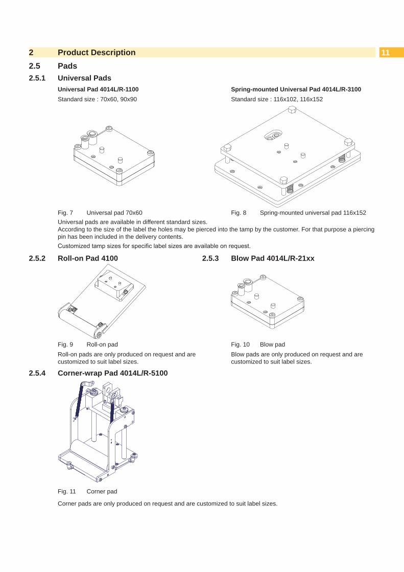
Universal Pad 4014L/R-1100 Spring-mounted Universal Pad 4014L/R-3100Standard size : 70x60, 90x90 Standard size : 116x102, 116x152
Fig. 7 Universal pad 70x60 Fig. 8 Spring-mounted universal pad 116x152Universal pads are available in different standard sizes. According to the size of the label the holes may be pierced into the tamp by the customer. For that purpose a piercing pin has been included in the delivery contents.Customizedtampsizesforspecificlabelsizesareavailableonrequest.
2.5.2 Roll-on Pad 4100 2.5.3 Blow Pad 4014L/R-21xx
Fig. 9 Roll-on pad Fig. 10 Blow padRoll-on pads are only produced on request and are customized to suit label sizes.
Blow pads are only produced on request and are customized to suit label sizes.
2.5.4 Corner-wrap Pad 4014L/R-5100
Fig. 11 Corner pad
Corner pads are only produced on request and are customized to suit label sizes.

12 123 Operation3.1 Standard Operation
Check all external connections. Load the material. Open the shutoff valve.
! Attention! Ensure that the pad is not covered by a label when switching on the printer-applicator system.
Otherwise the vacuum sensor may be calibrated incorrectly.
Switch on the printer.
i Note! If the pad is not in the starting position when the printer is switched on an error message will appear on the display.Press pause button on the printer. The applicator will move into the start position and is ready for work.
Press the feed button on the printer. A synchronization feed is initiated. The processed labels have to be removed manually. After a few seconds the printer carries out a short backfeed to position the front edge of the next label at the printing line.
i Note!This synchronization also has to be carried out when the print job has been interrupted with the cancel button.Synchronizing is not necessary when the print head was not lifted between print jobs. This also applies if the printer was powered off between print jobs.
Start a print job. Start the labelling process via PLC interface.
Error messages during labelling process are shown in the display of the printer Error Messages.
3.2 Cleaning
! Attention!Never use solvents and abrasives.
1
Clean the outside surfaces with multi purpose cleaner. Remove dust particles and leftover label pieces with a soft
brush and/or vacuum cleaner. The slide foil (1) requires regular cleaning as most of the
dirt will accumulate here.
Fig. 12 Cleaning the pad

133 Operation
1
1
2
2
6
7
3
4
5
Fig. 13 Mounting the applicator to the printer
! Attention!Initiation,adjustmentsandchangingofpartsistobeperformedbyqualifiedservicepersonnelonly. Service Manual of the Applicator
! Attention! Disconnect the printer from the power supply before mounting the applicator! Ensure the printer is in a stable position! Connect the compressed air only after mounting the applicator to the printer!
To clean the applicator and printer it is sometimes necessary to turn away or even dismount the applicator from the printer. Take care not to adjust the setting screws, throttle valves or other alignment elements. This will enable use of the applicator directly after cleaning.
Pivot Away/Dismount the Applicator1. Loosen thumbscrew (5) and pivot the applicator aside.2. Disconnect SUB-D 15 male connector (6) from the female connector (7) of the printer.3. Loosen screw (4) and remove the locking plate (3) from the hinges.4. Lift the applicator from the hinges.Mount the Applicator5. With the female parts (1) of hinges hang the applicator on the hinges parts (2) of the printer.6. Connect the SUB-D 15 male connector (6) to the female connector (7) of the printer.7. To secure the applicator against slipping out of hinges, loosen screw (4), move metal part (3) under the hinge and
tighten screw (4).8. Swing the applicator to the printer and tighten the thumbscrew (5).

14 144 Error Messages4.1 Error Messages of the Printer
For detailed information about printer errors (e.g. 'Paper out', 'Ribbon out', etc.) Check the operator's manual of the printer.Error treatment:
Clearing the error results. Press the feed key to synchronize the label feed, remove the left over labels manually. Press the pause key to quit the error state.
After error correction, the label causing the error will be reprinted.
4.2 Error Messages of the ApplicatorThefollowingtablecontainsanoverviewofapplicatorspecificerrormessagesandtheirpossiblecauses.Italsosuggests methods to resolve the error states:
Error Message Possible Cause
Air pressure ins. Compressed air is switched offPressure to low < 4 barPressure to high > 6 bar
Label not depos. Label has not been placed onto the product; after the pad has moved back the label is still sticking to the pad.
Lower position Pad has not reached the starting position within 2s after the pad has left the labelling position; or pad has left the starting position without authorization.
Process Error Process of labeling was interrupted via the I/O interface of the printer with the STP signal.
Refl. sensor blk. There has been no change of state of the upper sensor of the cylinder from the start of the labelling process and the signal of the labelling position sensor.
Upper position Pad is not in the starting position when the printer was switched on.Pad has not reached the labelling position within 2s after the movement of the pad was started.Pad has left the printing position without authorization.
Vac. plate empty Label has not been picked up properly by the pad; or label fell off the pad before it could be placed onto the product.
Table 2 Error messages of the applicator
Error treatment: Clear the error results. Press the pause key to quit the error state.
i Note!In the case of errors check the Service Manual for adjustments and settings.
!Warning!After the error has been resolved the pad will immediately move back to the starting position!Dangerofinjurytohandsandfingersbythemovingpad!
Do not reach into the area of the moving pad and keep long hair, loose clothes, and jewelry away.
After error correction, the printing of the label causing the error cannot be repeated without restarting the print job except the error "Vac. plate empty" . In this case, the last label will be printed again after resolution via the pause key and then pressing the Enter button .
Intheapplicationmode"Apply/Print"sendsthesignal"Printfirstlabel"orpressthebutton to send a printed label to the tamp.

155 Licences5.1 Declaration of Incorporation
cab Produkttechnik GmbH & Co KG Wilhelm-Schickard-Str. 14 D-76131 Karlsruhe Germany
Declaration of Incorporation
We declare herewith that the following „partly completed machinery“ as a result of design, construction and the version put in circulation complies with the essential requirements of the Directive 2006/42/EC on machinery:Annex I, Article 1.1.2, 1.1.3, 1.1.5, 1.1.6, 1.2.1, 1.3.2, 1.5.2, 1.5.8, 1.6.3, 1.7In the event of any alteration which has not been approved by us being made to any device as designated below, this statement shall thereby be made invalid.
Device: Stroke ApplicatorType: 4014/4016
Applied EU Regulations: Applied Standards:Directive 2006/42/EC on machinery: • EN ISO 12100:2010
• EN ISO 13849-1:2008• EN 60950-1:2006
+A11:2009+A12:2011+A1:2010+A2:2013Other Relevant Directives:• Directive 2014/30/EU relating to electromagnetic compatibility• Directive 2011/65/EU on the restriction of the use of certain hazardous substances in electrical and
electronic equipment
Personauthorisedtocompilethetechnicalfile: Erwin Fascher Am Unterwege 18/20 99610 Sömmerda
Signed for, and on behalf of the Manufacturer:
cab Produkttechnik Sömmerda Gesellschaft für Computer- und Automationsbausteine mbH 99610 Sömmerda
Sömmerda, 19.06.2017
Erwin FascherManaging Director
Theproductmustnotbeputintoserviceuntilthefinalmachineryintowhichitistobeincorporatedhasbeendeclaredinconformity with the provisions of the Directive on machinery.The documents according annex VII part B from the incomplete machinery are created and will commit to state agencies on request in electronic kinds.

16 165 Licences5.2 EU Declaration of Conformity
cab Produkttechnik GmbH & Co KG Wilhelm-Schickard-Str. 14 D-76131 Karlsruhe Germany
EU Declaration of Conformity
We declare herewith that the following device as a result of design, construction and the version put in circulation complies with the relevant fundamental regulations of the EU Rules for Safety and Health. In the event of any alteration which has not been approved by us being made to any device as designated below, this statement shall thereby be made invalid.
Device: Stroke ApplicatorType: 4014/4016
Applied EU Regulations: Applied Standards:Directive 2014/30/EU relating to electromagnetic compatibility: • EN 55032:2012
• EN 55024:2010• EN 61000-6-2:2005
Directive 2011/65/EU on the restriction of the use of certain hazardous substances in electrical and electronic equipment:
• EN 50581:2012
Signed for, and on behalf of the Manufacturer:
cab Produkttechnik Sömmerda Gesellschaft für Computer- und Automationsbausteine mbH 99610 Sömmerda
Sömmerda, 19.06.2017
Erwin Fascher Managing Director

176 Installation6.1 Factory default Settings
i Note! Theapplicatorissetupinastandardconfigurationbythefactory.Thesevaluesguaranteeareliableoperation.
i Note! Inthecaseofacustomerspecificsetupwithspecialmaterialthesettingscandeviatefromthestandardvalues. In this case the standard values in the setup protocol are as follows.
The factory default settings are:• Connected to a cab Hermes+ printer, vertical• Used Pad: cab part No.: 5963881 54x36 for L
cab part No.: 5963878 54x36 for R• Material used for factory default settings: cab part No.: 5556472 54x35.5 • Pressure value of the compressed air: 0.45 MPa (4.5 bar)

18 186 Installation6.2 Tools
Screwdriver with parallel blade 2.5 • To adjust the throttle valves and product sensor
Hexagon key L-wrench 0.8 • To adjust the sensors (in contents of delivery)
2.5 • For matched norm parts (in contents of delivery)
4 • Pad adjustments Changing pad
Flat-round nose - straight - angled
• To mount/dismount tubes
Open spanner SW 8 • To change the throttle valves
SW 13 • Setting the spring power on the adapter bolt
SW20 • Changing the cylinderManometer ± 7 bar • Air pressure control
Table 3 Tools
6.3 Mounting and Dismounting the CoverTo initiate the applicator or for adjustments it is necessary to dismount the cover (2). After these adjustments have been completed remount the cover.
!Warning!
Do not operate the applicator without cover (2). Only dismount the cover when servicing the applicator.
2
3
1Dismount1. Loosen screw (3).2. Lift off cover (2).
Mount3. Move the cover (2) over the cylinder assembly. 4. Put in the cylinder (1) through the hole in the cover
(2).5. Tighten screw (3) to fasten the cover (2).
Fig. 14 Cover

196 Installation6.4 Mounting the Applicator to the Printer
! Attention! Disconnect the printer from the power supply before mounting the applicator! Ensure the printer is standing in a stable position! Connect the compressed air only after mounting the applicator to the printer!
1
1
2
2
6
7
345
1. Hang the applicator to the printer via the female hinges (1) to the male hinges (2) of the printer.
2. Connect the SUB-D 15 male connector (6) to the female connector (7) of the printer.
3. To ensure the applicator does not slip out of the hinges, loosen screw (4), move the locking plate (3) to secure the applicator and tighten screw (4) again.
4. When pivoting the applicator onto the printer ensure that the cable is not caught between the two units.
5. Tighten the thumbscrew (5).6. Raise the stopper on the rail to enable
movement of the lifting cylinder. „6.5 Transpor-tation Lock“
Fig. 15 Mounting applicator to the printer
6.5 Transportation Lock
1
32
1
32
4
3
Fig. 16 Stopper as transportation lock
When the applicator is delivered, the stopper (2) is mounted on the rod (1). With this stopper (2) the labelling position for the operation mode "Blow on" can be adjusted. In delivery status the stopper (2) is used as transportation lock.
i Note! To reduce the impact energy it is possible to use a stopper with cushioning (4).
Releasing the transportation lock
1. Loosen screw (3) of the stopper (2).2. Move the stopper (2) along the rod (1) into the position as in operation mode:
- Operation mode "Blow on": 7.4 Adjusting the stopper - Operation mode "Stamp on" : Move the stopper (2) up to the end of the rod (1).
3. Tightenscrew(3)tofixthestopper(2)inposition.

20 206 Installation6.6 Mounting the Pad
1
2
45
6 8
73
1. Insert the pins (6) of the pad (8) into the holes on the bottom of the pad holder (7).
2. Fix the pad (8) to the pad holder (7) with the screws (1).
3. Insert the vacuum tube (2) and the air blowing tube(3)intotheirappropriatepush-in-fittings(4 & 5) of the pad.
Fig. 17 Mounting the pad
! Attention! To avoid possible collisions of the pad with other parts of the printer-applicator system, please roughly
align the pad in all directions („7.1 Pad Adjustments“) before connecting the applicator to the compressed air supply!
6.7 Piercing the Universal Pad Sliding FoilOn the bottom of the pad there are holes for holding the labels in place by vacuum. The universal pad is delivered with these holes are covered by a sliding foil and must be punctured according to used the label size. For that purpose a piercing pin is included in the contents of delivery.
!Attention!Danger of stabbing injuries in case of inappropriate use.
1 2 3
4
2 mm
1. Place a label (1) on the bottom of the pad (2). Note the position of the slanted edge (3).
2. Align the label so that it protrudes about 2 mm over the slanted edge.
3. Pierce holes into the sliding foil with the piercing pin (4) that are clearly covered by the label as illustrated. Ensure the holes are free of sliding foil by twisting the piercing pin.
Fig. 18 Piercing the sliding foil of the universal pad
! Attention!Do not pierce holes into the sliding foil which are located less than 1 mm from the label's edge as this will compromisethevacuumsefficiency.
216 Installation6.8 Preparing the Applicator for the Spring Mounted Pad 401x-4x00
! Attention!Ensure the cylinder assembly does not get damaged or cause injury when loosening screws to perform adjustments.
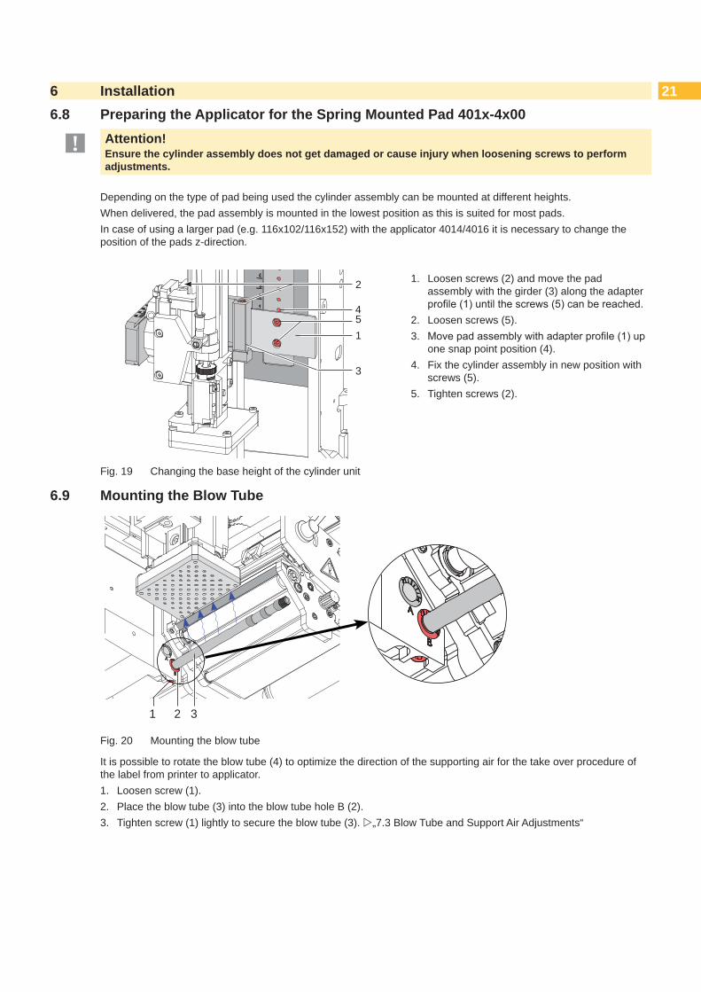
Depending on the type of pad being used the cylinder assembly can be mounted at different heights.When delivered, the pad assembly is mounted in the lowest position as this is suited for most pads. In case of using a larger pad (e.g. 116x102/116x152) with the applicator 4014/4016 it is necessary to change the position of the pads z-direction.
5
2
3
1
4
1. Loosen screws (2) and move the pad assembly with the girder (3) along the adapter profile(1)untilthescrews(5)canbereached.
2. Loosen screws (5).3. Movepadassemblywithadapterprofile(1)up
one snap point position (4). 4. Fix the cylinder assembly in new position with
screws (5). 5. Tighten screws (2).
Fig. 19 Changing the base height of the cylinder unit
6.9 Mounting the Blow Tube
1 2 3
Fig. 20 Mounting the blow tube
It is possible to rotate the blow tube (4) to optimize the direction of the supporting air for the take over procedure of the label from printer to applicator.1. Loosen screw (1).2. Place the blow tube (3) into the blow tube hole B (2).3. Tighten screw (1) lightly to secure the blow tube (3). „7.3 Blow Tube and Support Air Adjustments“
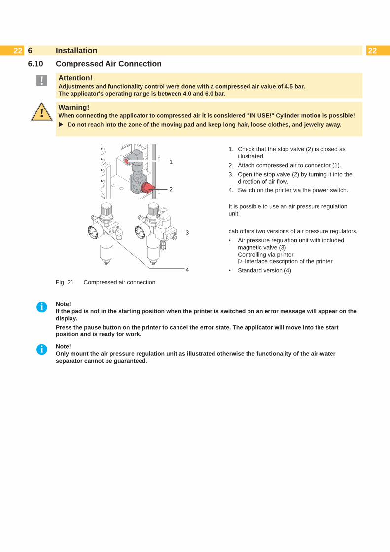
22 226 Installation6.10 Compressed Air Connection
! Attention!Adjustments and functionality control were done with a compressed air value of 4.5 bar. The applicator's operating range is between 4.0 and 6.0 bar.
! Warning!When connecting the applicator to compressed air it is considered "IN USE!" Cylinder motion is possible!
Do not reach into the zone of the moving pad and keep long hair, loose clothes, and jewelry away.
2
1
3
4
1. Check that the stop valve (2) is closed as illustrated.
2. Attach compressed air to connector (1).3. Open the stop valve (2) by turning it into the
directionofairflow.4. Switch on the printer via the power switch.
It is possible to use an air pressure regulation unit.
cab offers two versions of air pressure regulators.• Air pressure regulation unit with included
magnetic valve (3) Controlling via printer Interface description of the printer
• Standard version (4)
Fig. 21 Compressed air connection
i Note! If the pad is not in the starting position when the printer is switched on an error message will appear on the display.Press the pause button on the printer to cancel the error state. The applicator will move into the start position and is ready for work.
i Note! Only mount the air pressure regulation unit as illustrated otherwise the functionality of the air-water separator cannot be guaranteed.

237 Adjustments7.1 Pad Adjustments
For optimal functionality it is necessary to place the pad exactly over the label for the takeover procedure.
Moving the Pad in X-, Y- and Z-Directions
7 1 mm
1 m
m
6
1
3
2
4
5y
x
z
yx
z
Fig. 22 Moving the pad assembly
Adjustment in the X-direction - Sideways Adjustment 1. Loosen screw (3).2. Move the cylinder assembly group (4) including pad along the cross beam until the pad is over the middle of
the label intended for application. For better orientation there is a graduation mark (5) depicted on the assembly group.
3. Tighten screw (3).
Adjustment in the Y-direction - Print Direction
1. Loosen screws (1). 2. Move cylinder assembly (4) including pad along the guide rail so that the distance between the edge of the pad
(6) and the edge of the dispense plate (7) of the printer is approximately 1 mm.3. Tighten screws (1).
Adjustment in Z-direction - Height Adjustment1. Loosen screw (3).2. Turn setting screw (2) so that the bottom of the pad is 1 mm over the top edge of the dispense plate (7).3. Tighten screw (3).
Adjusting the Parallelism between Pad and Dispense Edge
The edge of the pad must be parallel to the dispense edge of the printer.
11
10
8 9
3 46 7
Fig. 23 Adjusting the pad to the dispense edge
1. Loosen knurled screw (10) and screw (9).2. Press the applicator against the printer and adjust the angle between applicator pad edge (6) and printer
dispensing plate (7) via the setting screw (11) and the eccentric (8).3. Tighten screw (9) and fasten the applicator with knurled screw (10).

24 247 Adjustments7.2 Vacuum Adjustments
The label will be held on the pad by a vacuum.The vacuum needs to be set up in such a way that the label covers all the suction holes and is not hindered before it reaches its intended position on the pad.
The default Value of the Vacuum is -0.6 bar.
support air
vacuum1
Fig. 24 Throttle valve "vacuum"
Adjust the vacuum on the throttle valve "vacuum" (1) so that the label will be sucked up over its entire area. To increase the vacuum turn the setting screw on the throttle valve (1) counterclockwise.
Measuring Point Vacuum (MP V)
MP V
123
Fig. 25 Measuring points for the vacuum
Use a manometer with a measurement range of -7 to 7 bar to control the pressure.
MP V : Vacuum - Reference Value (-0.6 bar)
1. Remove cover.2. Cover the suction plate so it is airtight.3. Attach manometer between tube (1) of the energy
chainandfitting(2)ofthepad.4. Activate the magnetic valve manually by pressing
the micro switch (3) to measure the pressure.5. Mount cover.
! Attention!After pressure measurements, reconnect all components correctly.
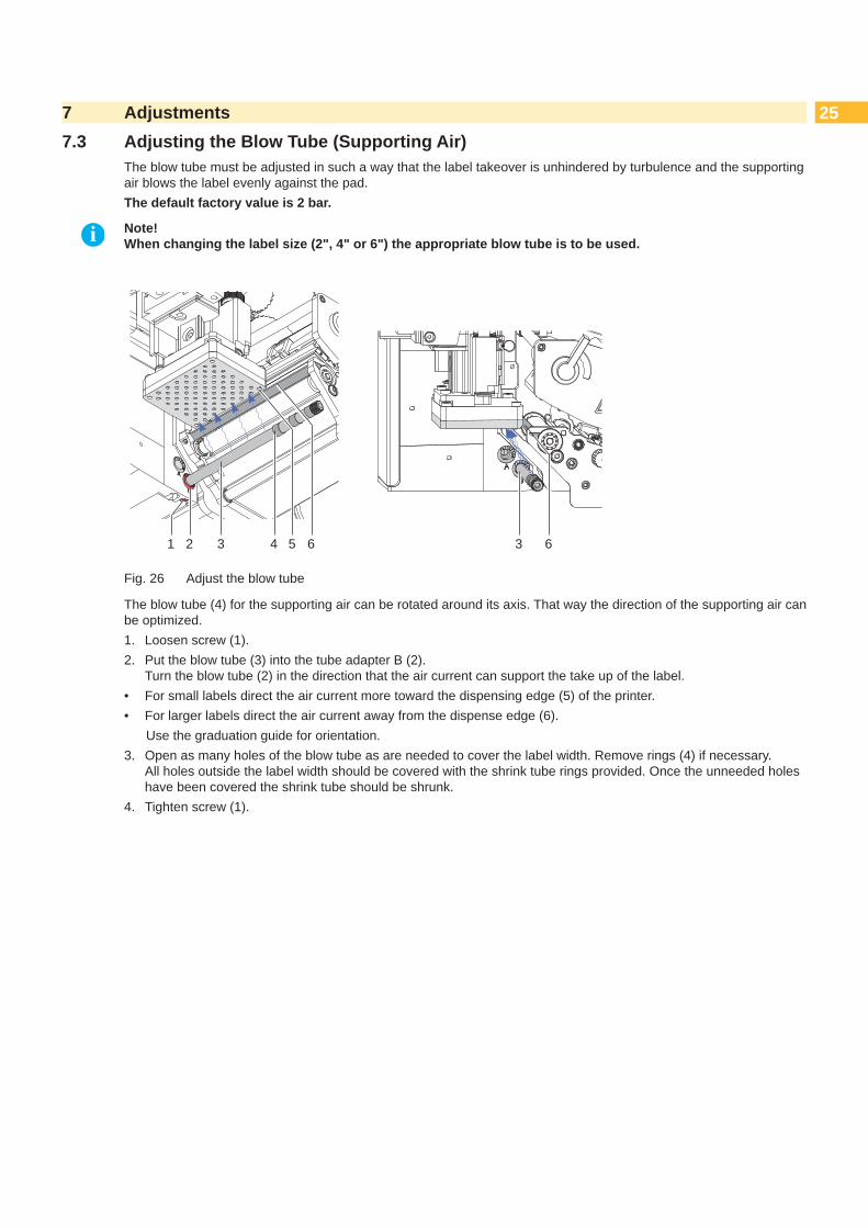
257 Adjustments7.3 Adjusting the Blow Tube (Supporting Air)
The blow tube must be adjusted in such a way that the label takeover is unhindered by turbulence and the supporting air blows the label evenly against the pad.The default factory value is 2 bar.
i Note! When changing the label size (2", 4" or 6") the appropriate blow tube is to be used.
1 2 3 4 5 6 3 6
Fig. 26 Adjust the blow tube
The blow tube (4) for the supporting air can be rotated around its axis. That way the direction of the supporting air can be optimized.1. Loosen screw (1).2. Put the blow tube (3) into the tube adapter B (2).
Turn the blow tube (2) in the direction that the air current can support the take up of the label.• For small labels direct the air current more toward the dispensing edge (5) of the printer.• For larger labels direct the air current away from the dispense edge (6). Use the graduation guide for orientation. 3. Open as many holes of the blow tube as are needed to cover the label width. Remove rings (4) if necessary.
All holes outside the label width should be covered with the shrink tube rings provided. Once the unneeded holes have been covered the shrink tube should be shrunk.
4. Tighten screw (1).
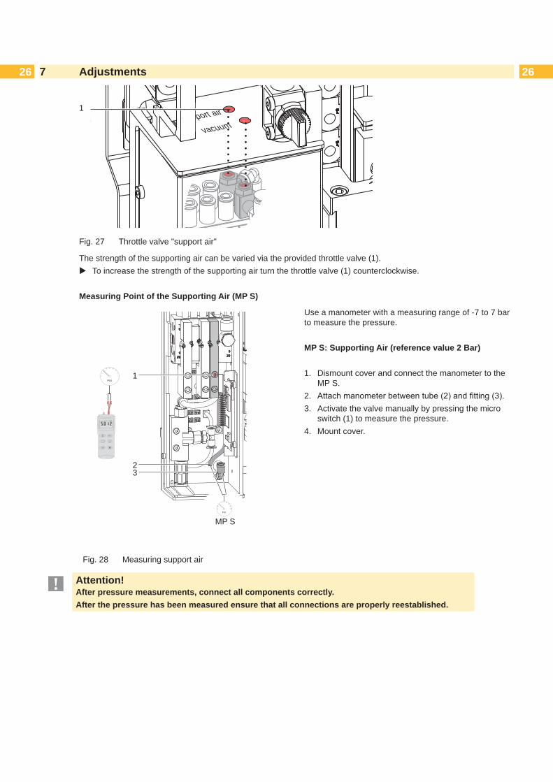
26 267 Adjustments
support air
vacuum
1
Fig. 27 Throttle valve "support air"
The strength of the supporting air can be varied via the provided throttle valve (1). To increase the strength of the supporting air turn the throttle valve (1) counterclockwise.
Measuring Point of the Supporting Air (MP S)
32
1
MP S
Fig. 28 Measuring support air
Use a manometer with a measuring range of -7 to 7 bar to measure the pressure.
MP S: Supporting Air (reference value 2 Bar)
1. Dismount cover and connect the manometer to the MP S.
2. Attachmanometerbetweentube(2)andfitting(3).3. Activate the valve manually by pressing the micro
switch (1) to measure the pressure.4. Mount cover.
! Attention!After pressure measurements, connect all components correctly.After the pressure has been measured ensure that all connections are properly reestablished.
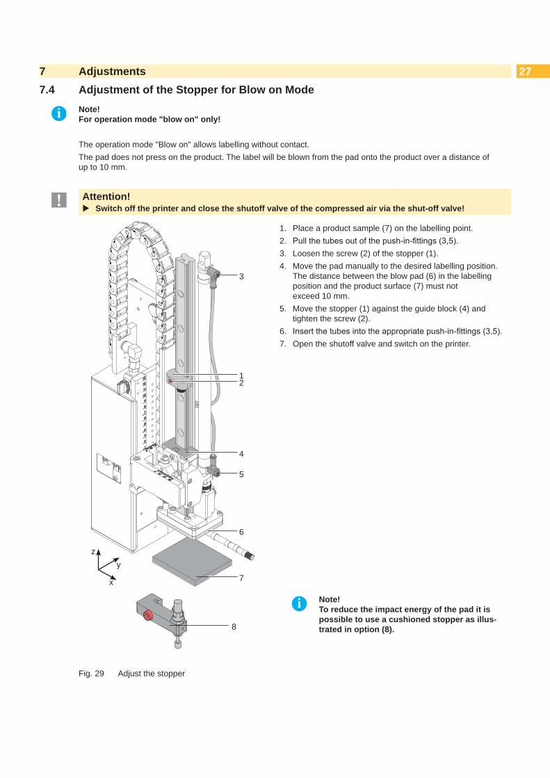
277 Adjustments7.4 Adjustment of the Stopper for Blow on Mode
i Note! For operation mode "blow on" only!
The operation mode "Blow on" allows labelling without contact.The pad does not press on the product. The label will be blown from the pad onto the product over a distance of up to 10 mm.
! Attention! Switch off the printer and close the shutoff valve of the compressed air via the shut-off valve!
3
12
6
7
5
4
y
x
z
8
1. Place a product sample (7) on the labelling point.2. Pullthetubesoutofthepush-in-fittings(3,5).3. Loosen the screw (2) of the stopper (1).4. Move the pad manually to the desired labelling position.
The distance between the blow pad (6) in the labelling position and the product surface (7) must not exceed 10 mm.
5. Move the stopper (1) against the guide block (4) and tighten the screw (2).
6. Insertthetubesintotheappropriatepush-in-fittings(3,5).7. Open the shutoff valve and switch on the printer.
i Note! To reduce the impact energy of the pad it is possible to use a cushioned stopper as illus-trated in option (8).
Fig. 29 Adjust the stopper

28 287 Adjustments7.5 Lifting Speed of Cylinder Z
1
2
43
5
Fig. 30 Throttle valves of the cylinder Z
The speed of the pad movement can be regulated by two throttle valves (1, 3). Adjust the pad movement speed as necessary. To increase the downward speed turn the screw (4) at the lower valve (3) counterclockwise. To increase the upward speed turn the screw (2) of the upper valve (1) counterclockwise.
i Note! The application pressure of the pad is mainly dependent on the downward speed of the pad.
In order to reduce the application pressure turn screw (4) clockwise.
! Attention!The time for the downward movement of the pad may not exceed 2 seconds otherwise the error message "Lower position" will appear.
i Note! To reduce the air pressure in Z-direction it is possible to use an optional pressure reduction valve (5). 7.8 Adjusting the Options for Z-direction Movement

297 Adjustments7.6 Sensors on Cylinder Z
6
4
5
321 10 mm
Fig. 31 Sensors on cylinder Z
Sensor Start Position 11. Loosen screw (1) of sensor "Start Position" (3) and move the sensor so that the top edge of the sensor sits
comfortably in the sensor holder. 2. Remove the compressed air tubes of the cylinder Z and power up the printer with connection to the applicator.3. Move the pad toward the stopper manually.4. Loosen screw (2) of the sensor holder.5. Position the sensor so that it triggers securely, with lit up LED, when cylinder Z is completely contracted. This is
achieved with the top edge of the sensor being about 10 mm from the top edge of the connection ring. (Fig. 31)6. Tighten screw (2).
Labelling Sensor 2The position of the labelling sensor (6) is dependant on the pad assembly's weight and the mounting position. The spring tension on the adapter bolt is dependant on these parameters and must be adjusted so that the sensor cannot trigger unintentionally. The triggering magnet is integrated in the adapter bolt and changes position with the tension spring.
MagnetDetection point in sensorSensor
Pad free Pad on product
MagnetDetection point in sensor
Sensor
Setting nut, black with cut-out 13mm
Knurled nut
Fig. 32 Labelling sensor principle
1. Gettingtheprinterandapplicatorintothefinalorientation.2. Adjust the spring tension on the adapter bolt (4) via the black setting nut so that:• The adapter bolt is not pushed into the stamp assembly group during motion.• The sensor triggers when the pad has reached the labeling position.3. Turnthesettingnutwithanopenspanner13mmandfixtheknurlednutbyholdingit.• Turning the setting nut clockwise will increase the spring tension.• Turning the setting nut counterclockwise will decrease the spring tension. 4. Loosen screw (5) and move the sensor (6) so that the LED lights up when the adapter bold is pushed into the pad
assembly. 5. Tighten screw (5).

30 307 Adjustments7.7 End Position Cushioning
i Note! Theendpositioncushioningofthecylinderissetuptoclientspecificationsanddoesusuallynotneedtobeadjusted.
2
1
The end position cushioning of the main cylinder reduces the impact energy when the applicator is operating at high speeds and/or masses. Adjust the end position cushioning so that the piston arrives theendpositiondefinitivelybutdoesnotstrikeittohard.A higher level of end position cushioning will reduce the lift speed.
To increase the value of the end position cushioning turn the setting screw (2) clockwise on cylinder (1).
To reduce the value of the end position cushioning turn the setting screw (2) counterclockwise on cylinder (1).
Fig. 33 End position cushioning
7.8 Adjusting the Options for Z-Direction Movement
Fig. 34 Stopper with cushioning (guide rail)
The stopper with cushioning (guide rail) reduces the speed of the cylinder Z shortly before impact when the applicator is operated at higher speeds and/or with larger pads.Adjustments like chapter „7.4 Adjustment of the Stopper for Blow on Mode“ Adjust the stopper with maximum compressed spring. „6.5 Transportation Lock“
Fig. 35 Stopper (pad assembly)
The stopper avoids the triggering of the labelling sensor by the weight of the pad assembly during the inward motion of an installation turned 90° or 180°.The setting occurs during the take-up of the label from the printer.1. Loosen the counter nut of the stopper.2. Turn the stopper until it touches the pad retainer lightly.
Do not change the take over position of the pad by via stopper.
3. Tightenthecounternuttofixthestopper.
32
1
MP S
1
2
3
Fig. 36 Pressure reduction valve cylinder Z
The pressure reduction valve (2) can be used when labelling pressure-sensitive products or considering general safety aspects to reduce the pressure of the cylinder in the Z-direction. The standard value is 2.5 bar.
Connect the manometer between tube and exit (3) and adjust the pressure to 2.5 bar with the knurled screw (1).
It is possible to order an upgraded set with a pressure reduction valve.Instructions are provided with the upgraded set.

317 Adjustments7.9 Labeling from below - Changing the Spring of the Impact Sensor
For fault free labeling in a sideways- or upward-motion it is necessary to change the spring of the impact sensor.The stronger spring prevents the unwanted triggering of the impact sensor due to the inertia of the cylinder and stamp assembly group.
1
2
Fig. 37 Demounting the stamp
Loosen screw (1) and dismount the stamp (2) to reach the locking washer (6).
3
4
5
6
Fig. 38 Loosening the adapter bolt
Push the adapter bolt (3) into the stamp uptake (4) to ensure that the bottom of the bottom of the bolt is pushed out. Demount locking plate (6).
Remove washer (5).
3
7
4
Fig. 39 Changing the spring
Hold onto the adapter bolt (3) and pull off the stamp uptake (4). Pull out the pressure spring (6) and replace it with the alternative. Push together the stamp uptake (4) and the adapter bolt (3). Replace the washer (5). Place the locking washer (6) back into it's position.
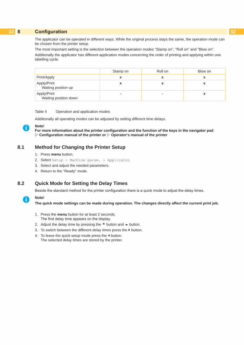
32 328 ConfigurationThe applicator can be operated in different ways. While the original process stays the same, the operation mode can be chosen from the printer setup.The most important setting is the selection between the operation modes "Stamp on", "Roll on" and "Blow on". Additionally the applicator has different application modes concerning the order of printing and applying within one labelling cycle.
Stamp on Roll on Blow onPrint/Apply x x xApply/Print Waiting position up
x x x
Apply/Print Waiting position down
- - x
Table 4 Operation and application modes
Additionally all operating modes can be adjusted by setting different time delays.
i Note! Formoreinformationabouttheprinterconfigurationandthefunctionofthekeysinthenavigatorpad Configurationmanualoftheprinteror Operator's manual of the printer
8.1 Method for Changing the Printer Setup1. Press menu button.2. Select Setup > Machine param. > Applicator.3. Select and adjust the needed parameters.4. Return to the "Ready" mode.
8.2 Quick Mode for Setting the Delay TimesBesidethestandardmethodfortheprinterconfigurationthereisaquickmodetoadjustthedelaytimes.
i Note!The quick mode settings can be made during operation. The changes directly affect the current print job. 1. Press the menu button for at least 2 seconds.
Thefirstdelaytimeappearsonthedisplay.2. Adjust the delay time by pressing the ~ button and � button.3. To switch between the different delay times press the } button.4. To leave the quick setup mode press the | button.
The selected delay times are stored by the printer.

338 Configuration8.3 ConfigurationParameters of the Applicator
TheconfigurationparametersoftheapplicatorcanbefoundinthemenuSetup > Machine param.
Parameter Meaning DefaultApplicator Configurationparametersoftheapplicator
> Mode of oper. Setting the operation mode Stamp on, Roll on, Blow on Stamp on
> Mode of appl. Setting the application mode Print-Apply/Apply-PrintPrint-Apply:An external start signal begins the printing of a label followed by the application of that label. After the cycle is complete, the pad waits in the start position without a label.Apply-Print:Aseparatesignalstartstheprintingofthefirstlabelandthetransfer of that label to the pad. The start signal applies that label and the next label is printed. The cycle ends with a printed label on the pad.
Print- Apply
> Waiting position
only for Mode of oper. Blow on and Mode of appl. Apply-Print
up : Pad waits in the start position for the start signal down : Pad waits in the labelling position for the start signal
up
> Blow time only for Mode of oper. Blow onThe length of time (max. 2.5 s) air is blown for the label transfer
0 ms
> Support delay on
Sets the delay (max. 2.5 s) for the supporting air after printing start and switching on the supporting air. The delay prevents turbulence at the front of the label and, consequently, prevents issues when the label is being picked up from the printer.
0 ms
> Support del. off
Setting the switch-off delay (max. 2.5 s) for the supporting air between the end of label forwarding and switching on the supporting air. The delay can be useful to separate the rear end ofthelabelfromthebackingtoavoidflawsandtoimprovetheaccuracy of label positioning
270 ms
> Delay time Delay (max. 2.5 s) between start signal and the start of a labelling cycle. Allows the use of product sensors within conveyors systems for example
0 ms
> Lock time Allstartsignalscominginafterthefirststartsignalareignoredwhen they arrive within the lock time.
0 ms
> Peel position Shift the position of the dispensed label relative to the dispensing edge. In the software an extra peel offset value is available. The offset values from “Peel position“ and from software are added together for execution. "Setting the Peel Position".
0.0 mm
> Vacuum control Setting the label transfer check from printer to pad and from pad to product by the vacuum sensor
On
> Hand-over up Take over the label directly from the dispensing edge with contact between pad and dispensing edge. Not applicable for Type 4014/4016
Off
> Cleaning blow Activate/Deactivate - air pressure pulses to clean the pad On
> Vacuum delay On - The vacuum will switched on after the end of the label transport. Off - The vacuum will switched on with the start of the label transport.
Off
Table 5 Applicator parameters

34 348 Configuration8.4 Setting the Peel Position
To optimize the transfer of the labels from the printer to the pad there are two different parameters available for adjusting the peel position.
! Attention! Firstadjusttheparameter"PeelPosition"intheprinterconfiguration. Then adjust the additional peel-off offset in the software.
It is very important to follow that procedure for a certain start after label loading and for the re-start after error treatment.
Parameter"PeelPosition"intheprinterconfiguration
Check the basic settings in the printer setup. Perform labelling cycles by alternately pressing the feed button and Enter button . „9.1 Test Mode without Print Job“
Adjust the "Peel Position" in such a way, that the blank labels are peeled-off completely from the liner „8.3ConfigurationParametersoftheApplicator“
Peel-off offset in the software
Check the setting in the software. Perform labelling cycles by repeatedly pressing the Enter button . „9.2 Test Mode with Print Job“.
Adjust the peel-off offset in such a way, that the printed labels are peeled-off completely from the liner Programming manual or software documentation.
8.5 Activation of Peel-off Mode
i Note! For labelling operation activate the peel-off mode in the software. For direct programming use the P command Programming manual.

359 Test Operation9.1 Test Mode without a Print Job
! Warning!The pad will be moved to the starting position immediately!Dangerofinjurytohandsandfingersbythemovingpad!
Do not reach into the zone of the moving pad and keep long hair, loose clothes, and jewelry away.
2
1
Fig. 40 Test mode with the enter button
i Note! Please use this test mode to adjust the parameter "peelposition"intheprinterconfiguration.
The whole labelling process can be simulated without the need of a print job or a connection to a computer by alter-nately pressing the feed button (2) and the Enter button (1):
Press the feed button (2). A blank label is fed. The vacuum at the pad as well as the supporting air (blow tube) are switched on. After the label has been picked up by the pad, the supporting air is switched off.
Press the Enter button (1). The pad is moved to the labelling position. A sensor signals when the labelling position is reached. The vacuum is switched off and the label is placed onto the product. Then, the pad is moved back into the starting position.
9.2 Test Mode with Print Job
i Note! Please use this test mode to adjust the peel-off offset in the software.
This method allows to check labelling processes with the real print data using the Enter button (1). Send a print job.
The test mode is executed in two half cycles: Press the Enter button (1).
Half cycle 1 A label is printed. The vacuum of the pad as well as the supporting air (blow tube) are switched on. After the label has been picked up by the pad, the supporting air is switched off.
Press the Enter button (1) again. Half cycle 2 The pad is moved to the labelling position. A sensor signals when the labelling position is reached. The vacuum is switched off and the label is placed onto the product. Then, the pad is moved back into the starting position.

36 3610 Spare Parts10.1 Retainer Assembly
Fig. 41 Retainer assembly - spare parts
No. Part-No. Description PU Serial No.from to
1 5902489.001 Screw DIN7984-M4x8 102.1 5964129.001 Cover L 12.2 5964260.001 Cover R 13 5964367.001 Knurled Screw 14 5964104.001 Set Screw 15 5904544.001 Spring 106 5964090.001 Bar 17.1 5964429.001 Plate L 17.2 5964438.001 Plate R 18 5902021.001 Screw DIN7991-M3x6 109 5903525.001 E-Ring DIN6799-0 10
10.1 5964036.001 Mounting Plate L 110.2 5964185.001 Mounting Plate R 1
No. Part-No. Description PU Serial No.from to
11.1 5964318.001 AdapterProfile L/R200/300H 111.2 5970013.001 AdapterProfile L400H 111.3 5970014.001 AdapterProfile R400H 112 5902167.001 Screw DIN912 M5x46 1013.1 5964312.001 Crossbeam 4014L 113.2 5964331.001 Crossbeam 4014R 113.3 5964332.001 Crossbeam 4016L 113.4 5964333.001 Crossbeam 4016R 114.1 5964310.001 Clamping Element L 114.2 5964328.001 Clamping Element R 115 5964062.001 Binder 198 5966530.001 Eccentric 199 5966529.001 Hinges 1
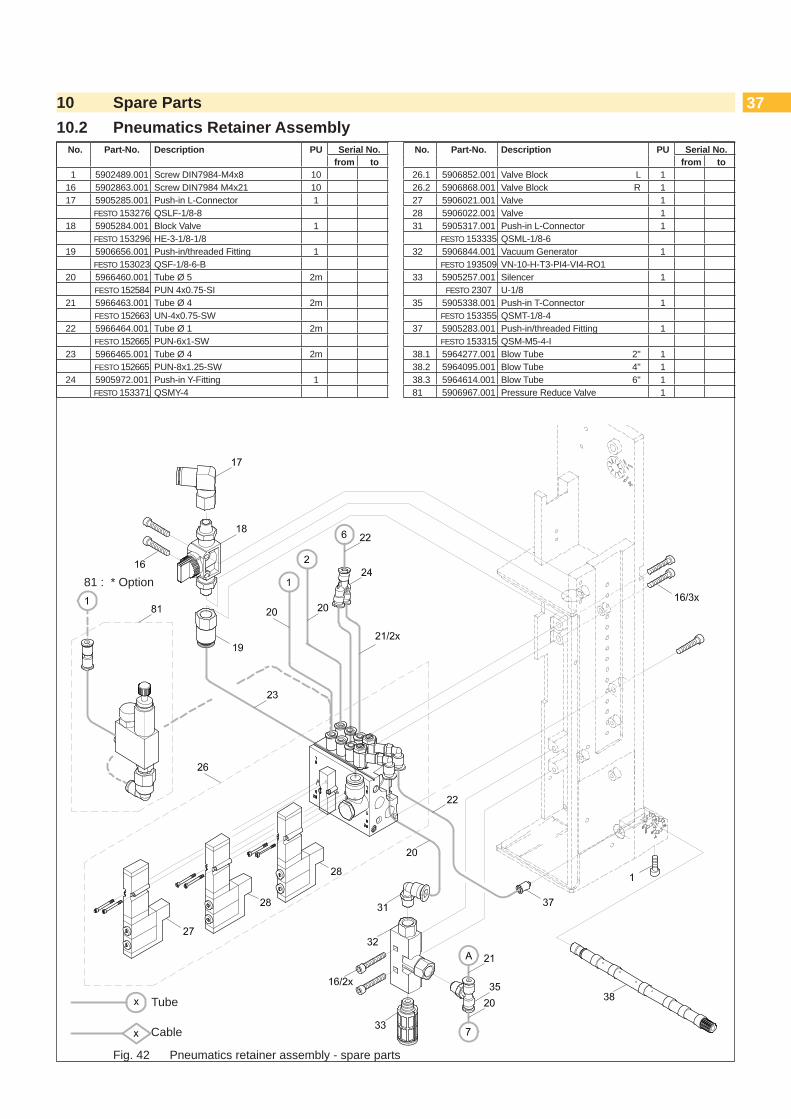
3710 Spare Parts10.2 Pneumatics Retainer Assembly
Fig. 42 Pneumatics retainer assembly - spare parts
81 : * Option
No. Part-No. Description PU Serial No.from to
1 5902489.001 Screw DIN7984-M4x8 1016 5902863.001 Screw DIN7984 M4x21 1017 5905285.001 Push-in L-Connector 1
FESTO 153276 QSLF-1/8-818 5905284.001 Block Valve 1
FESTO 153296 HE-3-1/8-1/819 5906656.001 Push-in/threaded Fitting 1
FESTO 153023 QSF-1/8-6-B20 5966460.001 Tube Ø 5 2m
FESTO 152584 PUN 4x0.75-SI21 5966463.001 Tube Ø 4 2m
FESTO 152663 UN-4x0.75-SW22 5966464.001 Tube Ø 1 2m
FESTO 152665 PUN-6x1-SW23 5966465.001 Tube Ø 4 2m
FESTO 152665 PUN-8x1.25-SW24 5905972.001 Push-in Y-Fitting 1
FESTO 153371 QSMY-4
No. Part-No. Description PU Serial No.from to
26.1 5906852.001 Valve Block L 126.2 5906868.001 Valve Block R 127 5906021.001 Valve 128 5906022.001 Valve 131 5905317.001 Push-in L-Connector 1
FESTO 153335 QSML-1/8-632 5906844.001 Vacuum Generator 1
FESTO 193509 VN-10-H-T3-PI4-VI4-RO133 5905257.001 Silencer 1
FESTO 2307 U-1/835 5905338.001 Push-in T-Connector 1
FESTO 153355 QSMT-1/8-437 5905283.001 Push-in/threaded Fitting 1
FESTO 153315 QSM-M5-4-I38.1 5964277.001 Blow Tube 2" 138.2 5964095.001 Blow Tube 4" 138.3 5964614.001 Blow Tube 6" 181 5906967.001 Pressure Reduce Valve 1
Cable
Tube
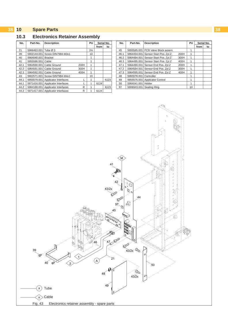
38 3810 Spare Parts10.3 Electronics Retainer Assembly
Fig. 43 Electronics retainer assembly - spare parts
No. Part-No. Description PU Serial No.from to
21 5966463.001 Tube Ø 3 2m39 5902144.001 Screw DIN7984-M3x1 1040 5964045.001 Bracket 141 5955586.001 Cable 142.1 5964590.001 Cable Ground 200H 142.2 5964591.001 Cable Ground 300H 142.3 5964592.001 Cable Ground 400H 143 5902571.001 Screw DIN7984-M4x1 1044.1 5955579.001 Applicator Interfaces L 1 612344.1 5971416.001 Applicator Interfaces L 1 612444.2 5964188.001 Applicator Interfaces R 1 612344.2 5971417.001 Applicator Interfaces R 1 6124
No. Part-No. Description PU Serial No.from to
45 5955585.001 PCB Valve Block assem. 146.1 5964454.001 Sensor Start Pos. Zyl.Z 200H 146.2 5964494.001 Sensor Start Pos. Zyl.Z 300H 146.3 5964495.001 Sensor Start Pos. Zyl.Z 400H 147.1 5964490.001 Sensor End Pos. Zyl.Z 200H 147.2 5964594.001 Sensor End Pos. Zyl.Z 300H 147.3 5964595.001 Sensor End Pos. Zyl.Z 400H 148 5955576.001 Controller 149 5955575.001 Applicator Control 150 5964041.001 Holder 197 5906943.001 Sealing Ring 10
Cable
Tube

3910 Spare Parts10.4 Guiding Cylinder Assembly
Fig. 44 Guiding cylinder assembly - spare parts
No. Part-No. Description PU Serial No.from to
47.1 5964490.001 Sensor End Pos. Zyl.Z 200H 147.2 5964594.001 Sensor End Pos. Zyl.Z 300H 147.3 5964595.001 Sensor End Pos. Zyl.Z 400H 151 5964343.001 Stopper* Option 152 5964364.001 Stopper 153 5964061.001 Setting Screw 154 5965966.001 Sliding Carriage 155.1 5964302.001 Plate L 155.2 5964337.001 Plate R 156 5903505.001 E-Ring DIN6799-1 1057.1 5964301.001 Holder L 157.2 5964336.001 Holder R 158 5902562.001 Screw DIN7984-M4x10 10
No. Part-No. Description PU Serial No.from to
59 5521159.001 Nut 160.1 5964236.001 Pad Retainer L 160.2 5964241.001 Pad Retainer R 161 5964311.001 Adapter Bolt 162.1 5905069.001 Spring 162.2 5905049.001 Spring 163 5521157.001 Washer 164 5521158.001 Washer 165 5903501.001 E-Ring DIN6799-3 1078 5964351.001 Stopper* 179.1 5964240.001 Plate L 179.2 5964244.001 Plate R 180 5902281.001 Screw DIN7984-M5x9 10
51, 78 : * Option
Cable
Tube
62.1: Labeling from above and horizontally
62.2: Labeling from below
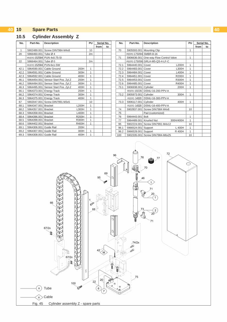
40 4010 Spare Parts10.5 Cylinder Assembly Z
Fig. 45 Cylinder assembly Z - spare parts
No. Part-No. Description PU Serial No.from to
1 5902489.001 Screw DIN7984-M4x8 1020 5966460.001 Tube Ø 4 2m
FESTO 152584 PUN 4x0.75-SI22 5966464.001 Tube Ø 0 2m
FESTO 152584 PUN-6x1-SW42.1 5964590.001 Cable Ground 200H 142.2 5964591.001 Cable Ground 300H 142.3 5964592.001 Cable Ground 400H 146.1 5964454.001 Sensor Start Pos. Zyl.Z 200H 146.2 5964494.001 Sensor Start Pos. Zyl.Z 300H 146.3 5964495.001 Sensor Start Pos. Zyl.Z 400H 166.1 5964373.001 Energy Track 200H 166.2 5964374.001 Energy Track 300H 166.3 5964375.001 Energy Track 400H 167 5902047.001 Screw DIN7991-M3x5 1068.1 5964347.001 Bracket L200H 168.2 5964357.001 Bracket L300H 168.3 5964358.001 Bracket L400H 168.4 5964396.001 Bracket R200H 168.5 5964398.001 Bracket R300H 168.6 5964402.001 Bracket R400H 169.1 5964306.001 Guide Rail 200H69.2 5964307.001 Guide Rail 300H 169.3 5964308.001 Guide Rail 400H 1
No. Part-No. Description PU Serial No.from to
70 5905593.001 Mounting Clip 1FESTO 175094 SMBR-8-16
71 5906636.001 One-way Flow Control Valve 1FESTO 175056 GRLA-M5-QS-4-LF-C
72.1 5964440.001 Cover L200H 172.2 5964483.001 Cover L300H 172.3 5964484.001 Cover L400H 172.4 5964451.001 Cover R200H 172.5 5964453.001 Cover R300H 172.6 5964485.001 Cover R400H 173.1 5906938.001 Cylinder 200H 1
FESTO 19235 DSNU-16-200-PPV-A73.2 5905973.001 Cylinder 300H 1
FESTO 14320 DSNU-16-300-PPV-A73.3 5906117.001 Cylinder 400H 1
FESTO 14320 DSNU-16-400-PPV-A74 5902837.001 Screw DIN7984 M4x8 1075 Pad (customized)76 5964443.001 Bolt 177 5964489.001 Knurled Nut 300H/400H 195 5902224.001 Screw DIN7991-M4x12 1096.1 5966524.001 Support L 400H 196.2 5966528.001 Support R 400H 1
100 5902335.001 Screw DIN7984-M6x25 10
Cable
Tube

4111 Drawings11.1 Block Diagram Type 4014/4016
44 Applicator Interfaces
CON 2
CON 1
C
ON
3
CO
N 1
1
CO
N 1
2
45Electronic
Valve Block
CON 1
C
ON
2
CO
N 3
C
ON
4
CO
N 5
49 Applicator Control
CON 1
Fig. 46 Block diagram 4014/4016
48 Controller
47 Sensor Labeling PositionCylinder Z
46 Sensor Start Position Cylinder Z
41 SUB-D 9 Interface To Printer
27 Magnetic Valve Cylinder Z
28 Magnetic Valve Blow Air
28 Magnetic Valve Support Air/Vacuum

42 4211 Drawings11.2 Pneumatic Drawing Type 4014/4016
Fig. 47 Pneumatics type 4014 / 4016

4311 Drawings11.3 Label Position Type 4014 L/4016 L
Fig. 48 Label position type 4014/4016 L
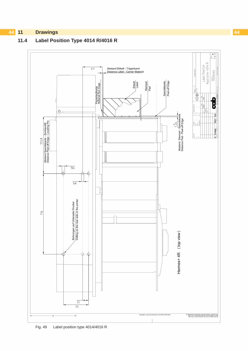
44 4411 Drawings11.4 Label Position Type 4014 R/4016 R
Fig. 49 Label position type 4014/4016 R

4512 IndexA
Applicator Control .............................40Applicator Interfaces .........................40
B
Block Diagram ..................................40Blow Mode ........................................27Blow on .............................................31Blow Tube ...................................21, 25
C
Cleaning ...........................................12Compressed Air ................................22Controller ..........................................40Cover ................................................18Cylinder Assembly
Guiding (Spare Parts) .................38Cylinder Z .........................................28
D
Declaration ofConformity ..................16Declaration of Incorporation .............15Delay Times ......................................31Delivery.............................................10
E
Electronic Valve Block ......................40End Position Cushioning ..................30Error Messages ................................14EU Regulations.................................16Ex Factory ........................................17
F
Features .............................................7
L
Labelling Sensor ...............................29Label position
401x L .........................................42401x R ........................................43
Label Position ...................................42Level of the cylinder unit ...................21Lift Speed .........................................28
M
Moving the tamp ...............................23
O
Options .......................................28, 30
P
Pad ...................................................20Parameters .......................................32Peel-off Mode ...................................33Peel position .....................................34Peel Position.....................................33Piercing.............................................20Pneumatic drawing ...........................41Pressure reduction ...........................30Pressure reduction valve ..................30Printer Setup.....................................31Print Job ...........................................34
R
Reading Point ...................................24Roll on ..............................................31
S
Sensor Start Position ........................29Stamp on ..........................................31Support Air ........................................25
T
Tamp pad, spring mounted ...............21Test Mode .........................................34Tools .................................................18Transport lock ...................................19
U
Universal Tamp Pad .........................20
V
Vacuum .............................................24
X
X-direction ........................................23
Y
Y-direction .........................................23
Z
Z-direction.........................................23