service manual - chigochigo.pl/wp-content/uploads/2017/01/r410a-lcac-service-manual... · service...
TRANSCRIPT

R410A50Hz Universal Outdoor Series Technical Manual Outdoor Unit
I GD Chigo Heating & Ventilation Equipment Co., Ltd.
R410A 50Hz Universal Outdoor Series
Service Manual
2012 Version

R410A50Hz Universal Outdoor Series Technical Manual Content
II GD Chigo Heating & Ventilation Equipment Co., Ltd.
PART 1.General Information ..................................................................................... 1
1.Nomenclature .................................................................................................................... 22.Model Names of Indoor/Outdoor Units ............................................................................ 43.External Appearance .......................................................................................................... 54.Features ............................................................................................................................. 7
Part 2 Indoor Unit ....................................................................................................... 84-Way Cassette Type ................................................................................................... 8
1. Features ............................................................................................................................ 92.Specification .................................................................................................................... 103.Dimension ........................................................................................................................ 124.Service Space ................................................................................................................... 135.Wiring Diagrams .............................................................................................................. 146.Capacity Table .................................................................................................................. 167.Electric Characteristics ..................................................................................................... 218.Sound Levels .................................................................................................................... 229.Exploded View ................................................................................................................. 2510.Accessories ..................................................................................................................... 3311.The Specification of Power ............................................................................................. 3412.Field Wiring ................................................................................................................... 3513.Troubleshooting ............................................................................................................. 36
Duct Type .................................................................................................................. 381.Features ........................................................................................................................... 392.Specification .................................................................................................................... 413.Dimensions ...................................................................................................................... 454.Service Space ................................................................................................................... 485.Wiring Diagrams .............................................................................................................. 496.Capacity Tables ................................................................................................................. 547.Static Pressure ................................................................................................................. 618.Electric Characteristics ..................................................................................................... 699.Sound Levels .................................................................................................................... 7010.Accessories ..................................................................................................................... 8111.The Specification of Wiring ............................................................................................ 8212.Field Wiring ................................................................................................................... 8313.Exploded View ............................................................................................................... 8414.Troubleshooting ............................................................................................................. 90
Floor & Ceiling ........................................................................................................... 921.Features ........................................................................................................................... 932.Specifications ................................................................................................................... 943.Dimensions ...................................................................................................................... 964.Service Space ................................................................................................................... 985.Wiring Diagrams .............................................................................................................. 996.Capacity Table ................................................................................................................ 101
Content

R410A50Hz Universal Outdoor Series Technical Manual Content
III GD Chigo Heating & Ventilation Equipment Co., Ltd.
7.Electric Characteristics ................................................................................................... 1058.Sound Levels .................................................................................................................. 1069.Exploded View ............................................................................................................... 10910.Accessories ................................................................................................................... 11311.The Specification of Power ........................................................................................... 11412.Field Wiring ................................................................................................................. 11513.Troubleshooting ........................................................................................................... 116
Part 3 Outdoor Units .............................................................................................. 1171.Specification .................................................................................................................. 1182.Dimensions .................................................................................................................... 1203.Service Space ................................................................................................................. 1224.Wiring Diagrams ............................................................................................................ 1235.Electric Characteristics ................................................................................................... 1296.Operation Limits ............................................................................................................ 1307.Sound Levels .................................................................................................................. 1318.Exploded View ............................................................................................................... 132
Part 4 Installation ................................................................................................... 1421.Precaution on Installation .............................................................................................. 1432.Vacuum Dry and Leakage Checking ................................................................................ 1443.Additional Refrigerant Charge ....................................................................................... 1464.Water Drainage .............................................................................................................. 1475.Insulation Work .............................................................................................................. 1506.Test Operation ................................................................................................................ 152
Part 5 Control ......................................................................................................... 1241.Wireless Remote Controller ........................................................................................... 1252.Wire Controller .............................................................................................................. 128

R410A50Hz Universal Outdoor Series Technical Manual General Information
1 GD Chigo Heating & Ventilation Equipment Co., Ltd.
PART 1.General Information
1.Nomenclature .......................................................................... 2
2.Model Names of Indoor/Outdoor Units .................................... 4
3.External Appearance ................................................................ 5
4.Features .............................................................................. 7
R410A 50Hz Universal Outdoor series

R410A50Hz Universal Outdoor Series Technical Manual General Information
2 GD Chigo Heating & Ventilation Equipment Co., Ltd.
1.Nomenclature
1.1. Indoor unit
C TCA -24 E B
C:Chigo HVAC
E:Electrical auxiliary heater.
Working Condition-:T1 condition; T:T3 condition.
Capacity,unit:kBtu/h
Design NoB:second des
i C
Function codeC:Cooling Only.
-:Match universal outdoor unit; i:match individual outd
Product seriesCA:4-way cassette; CB:Compact 4-way CasssetteTA;Low ESP Duct; TB:Mid ESP Duct; TH:High ESP Duct;UA:Floor & CeiliSG:Multi Wall type;SC:Multi 4-way Cassette;ST:Multi Duct.
- R1
Refrigerant-:R22; R1:R410A
V:DC Inv.-:Fixed speed.
V

R410A50Hz Universal Outdoor Series Technical Manual General Information
3 GD Chigo Heating & Ventilation Equipment Co., Ltd.
1.2. Outdoor unit
C OU3 -24 C B
C:Chigo HVAC
Function codeC:Cooling Only
Product seriesOU:Universal type.OT;Top-discharge; OW:Non-universal type
Capacity,unit:kBtu/h
Design NoB:second design.
T S
Power CodeS:380V/3Ph/50Hz
Working Condition-:T1 condition; T:T3 condition.
Match Code-:unitary series; 2:Multi 1 to 2; 3:Multi 1 to 3;
- R1
Refrigerant-:R22; R1:R410A
V:DC Inv.-:Fixed speed.
V

R410A50Hz Universal Outdoor Series Technical Manual General Information
4 GD Chigo Heating & Ventilation Equipment Co., Ltd.
2.Model Names of Indoor/Outdoor Units
2.1. Indoor Units Model name Dimension
(W×H×D) (mm) Net/Gross weight(kg) Power supply
CCB-18HR1 580×275×580 25/27 220~240V-1Ph-50Hz CCA-18HR1 840×230×840 26/32 220~240V-1Ph-50Hz CCA-24HR1 840×230×840 28/32 220~240V-1Ph-50Hz CCA-36HR1 840×285×840 31/35 220~240V-1Ph-50Hz CCA-48HR1 840×285×840 31/35 220~240V-1Ph-50Hz CCA-60HR1 840×285×840 31/35 220~240V-1Ph-50Hz
CTA-18HR1 1204×181×510 21/25 220~240V-1Ph-50Hz CTA-24HR1 1532×181×510 26/30 220~240V-1Ph-50Hz CTB-18HR1 1189×260×663 32/36 220~240V-1Ph-50Hz CTB-24HR1 1189×260×663 32/36 220~240V-1Ph-50Hz CTB-36HR1 1425×260×663 44/48 220~240V-1Ph-50Hz CTB-48HR1 1425×260×663 44/48 220~240V-1Ph-50Hz
CTB-48HR1-B 1200×364×625 60/64 220~240V-1Ph-50Hz CTB-60HR1-B 1200×364×625 60/64 220~240V-1Ph-50Hz
CTB-60HR1 1425×260×663 44/48 220~240V-1Ph-50Hz CTH-48HR1 1200×364×625 60/64 220~240V-1Ph-50Hz CTH-60HR1 1200×364×625 60/64 220~240V-1Ph-50Hz
CUA-18HR1 880×635×203 30/32 220~240V-1Ph-50Hz CUA-24HR1 1245×680×247 35/41 220~240V-1Ph-50Hz CUA-36HR1 1245×680×247 37/43 220~240V-1Ph-50Hz CUA-48HR1 1670×680×247 47/54 220~240V-1Ph-50Hz CUA-60HR1 1670×680×247 47/54 220~240V-1Ph-50Hz
2.2. Outdoor Units
Model name Dimension (W×H×D) (mm)
Net/Gross weight(kg) Power supply
COU-18HR1 815×286×535 49/51 220~240V-1Ph-50Hz COU-24HR1 930×370×700 58/61 220~240V-1Ph-50Hz COU-36HR1 1070×400×995 92/100 220~240V-1Ph-50Hz
COU-36HSR1 1070×400×995 92/100 380~415V-3Ph-50Hz COU-48HSR1 911×400×1335 96/107 380~415V-3Ph-50Hz COU-60HSR1 911×400×1335 96/107 380~415V-3Ph-50Hz

R410A50Hz Universal Outdoor Series Technical Manual General Information
5 GD Chigo Heating & Ventilation Equipment Co., Ltd.
3.External Appearance
3.1. Indoor unit 4-way Cassette
4-way cassette (Compact type)
Low ESP Duct
Middle ESP Duct
High ESP Duct(CTB-48HR1-B,CTB-60HR1-B)
High ESP Duct
Floor & Ceiling(COU-18HR1)
Floor & Ceiling

R410A50Hz Universal Outdoor Series Technical Manual General Information
6 GD Chigo Heating & Ventilation Equipment Co., Ltd.
3.2.Outdoor unit
COU-18HR1
COU-24HR1
COU-36HR1,COU-36HSR1
COU-48HSR1,COU-60HSR1

R410A50Hz Universal Outdoor Series Technical Manual General Information
7 GD Chigo Heating & Ventilation Equipment Co., Ltd.
4.Features
4.1 High quality coils The coil is constructed of advanced inner grooved copper tube and aluminum fins.
4.2 Low operation sound level: Well-known stable and quiet running fan motor. 4.3 Well-known compressor, Sanyo & Hitachi. 4.4 Compact design: Smaller dimension and larger stuffing capacity. 4.5 Universal outdoor unit design. 4.6 R410A environment friendly refrigerant. 4.7 CE certification, RoHS certification.
R410A50Hz Universal Outdoor Series Technical Manual 4 -way Cassette Indoor Unit
8 GD Chigo Heating & Ventilation Equipment Co., Ltd.
Part 2 Indoor Unit
4-Way Cassette Type
1. Features .................................................................................. 9
2.Specification ........................................................................... 10
3.Dimension ............................................................................... 12
4. Service Space ......................................................................... 13
5. Wiring Diagrams ..................................................................... 14
6. Capacity Table ........................................................................ 16
7. Electric Characteristics ............................................................ 21
8.Sound Levels ........................................................................... 22
9.Exploded View ........................................................................ 25
10.Accessories ............................................................................ 33
11.The Specification of Power .................................................... 34
12.Field Wiring .......................................................................... 35
13.Troubleshooting .................................................................... 36

R410A50Hz Universal Outdoor Series Technical Manual 4 -way Cassette Indoor Unit
9 GD Chigo Heating & Ventilation Equipment Co., Ltd.
1. Features
1.1 Brand-new panel design Simple, featly and voguish appearance suit for different requirements, it’s mostly used for office, shopping center, restaurant, meeting room and etc. 18kBtu/h, compact type, 650mm×650mm. 18kBtu~60kBtu/h, standard type, 950mm×950mm.
1.2 Ultra-thin body design, the min. height is only 230mm, save installation space. 1.3 4-way air flow, cold air can reach each corner of the room, providing a stable and comfortable
environment. 1.4 Intelligent auto-swing function, three modes for choice. 1.5 3 fan speed,meet for different requirement. 1.6 Three-dimensional centrifugal fan design. 1.7 Energy saving and healthy, adopting hydrophilic aluminum fins increasing heat-exchange. 1.8 Easy and convenient installation and maintenance, washable filter design. 1.9 Built-in water pump, water head up to 800mm (Compact type, 750mm). 1.10 Fire resistance design, the E-box with galvanized steel built-in body easy for maintenance. 1.11 Fresh air intake. 1.12 Multi protection and auto-restart function. 1.13 Standard for wireless controller; option for wired controller.

R410A50Hz Universal Outdoor Series Technical Manual 4 -way Cassette Indoor Unit
10 GD Chigo Heating & Ventilation Equipment Co., Ltd.
2.Specification
Model CCB-18HR1 CCA-18HR1 CCA-24HR1 Indoor power supply V/Ph/Hz 220~240/1/50 220~240/1/50 220~240/1/50
Cooling
Capacity Btu/h 18000 18000 24000
KW 5.3 5.3 7.1 Input W 85 64 120 Rated current A 0.39 0.29 0.55 EER W/W 2.67 2.70 2.82
Heating
Capacity Btu/h 19800 19800 26400
KW 5.8 5.8 7.8 Input W 85 64 120 Rated current A 0.39 0.29 0.55 COP W/W 3.27 3.31 3.51
Indoor fan motor
Model YDK-35T-41 YDK-35Q-8P3 YDK-55T-6 Input W 85 64 120 Capacitor μF 2.5 2.5 3 Speed(Hi/Med/Lo) r/min 1080/950/830 480/430/380 680/570/465
Indoor coil
Number of rows 2 2 2 Tube pitch x row pitch mm 21×12.7 21×12.7 21×12.7 Fin spacing mm 1.55 1.45 1.45 Fin type Hydrophilic Hydrophilic Hydrophilic
Tube outside dia. and type mm
Ф7 Ф7 Ф7 inner grooved inner grooved inner grooved
Coil size(W×H×D) mm 1137×210×25.4 1791×168×25.4 1791×168×25.4 Number of circuits 5 8 8
Indoor air flow(Hi/Med/Lo) m3/h 700/580/480 810/720/640 1100/920/750 Indoor noise level(Hi/Med/Lo) dB(A) 45/42/40 39/36/35 44/41/39
Indoor unit
Dimension(W×H×D) Body(mm) 580×275×580 840×230×840 840×230×840 Panel(mm) 650×30×650 950×50×950 950×50×950
Packing(W×H×D) Body(mm) 745×375×675 920×310×920 920×310×920 Panel(mm) 750×95×750 1030×105×1030 1030×105×1030
Net/Gross weight Body(Kg) 25/27 26/32 28/32 Panel(Kg) 4/5 5/7 5/7
Refrigerant type R410A R410A R410A Refrigerant piping
Liquid side/ Gas side mm Φ6.35/Φ12.7 Φ6.35/Φ12.7 Φ9.52/Φ15.88
Drainage pipe mm 25 25 25
Connection wiring
Power Supply From indoor unit From indoor unit From outdoor unit
Indoor power wiring mm2 2.5 2.5 1.0
Signal wiring mm2 1.5 1.5 0.75 Controller Standard for remote controller(wired controller for option) Operation temp °C 16~32 16~32 16~32
Ambient temp °C -7~43 -7~43 -7~43 Application area m2 20-35 20-35 28-50 Stuffing Quantity(20'/40'/40'HQ) 120/240/270 75/155/170 75/155/170
Notes: 1. Nominal cooling capacities are based on the following conditions: Indoor temp: 27°CDB, 19°CWB; Outdoor temp: 35°CDB; Equivalent ref. Piping: 7.5m(horizontal)
2. Nominal heating capacities are based on the following conditions: Indoor temp: 20°CDB; Outdoor temp: 7°CDB, 6°CWB; Equivalent ref. Piping: 7.5m(horizontal)
3. Actual noise level may differ, depending on the room structure, etc, since these noise values are from an anechoic room.

R410A50Hz Universal Outdoor Series Technical Manual 4 -way Cassette Indoor Unit
11 GD Chigo Heating & Ventilation Equipment Co., Ltd.
Model CCA-36HR1 CCA-48HR1 CCA-60HR1
Indoor power supply V/Ph/Hz 220~240/1/50 220~240/1/50 220~240/1/50
Cooling
Capacity Btu/h 36000 48000 60000
KW 10.5 14 16 Input W 160 180 180 Rated current A 0.73 0.82 0.82 EER W/W 2.71 2.70 2.72
Heating
Capacity Btu/h 39600 52800 66000
KW 11.5 15.4 16.6 Input W 160 180 180 Rated current A 0.73 0.82 0.82 COP W/W 3.31 2.92 2.78
Indoor fan motor
Model YDK-75T-6 YDK-75T-6P3-1 YDK-75T-6P3-1 Input W 160 180 180 Capacitor μF 4 5 5 Speed(Hi/Med/Lo) r/min 760/680/580 850/750/650 850/750/650
Indoor coil
Number of rows 2 2 2
Tube pitch x row pitch mm 21×12.7 21×12.7 20×17.32
Fin spacing mm 1.45 1.45 1.5 Fin type Hydrophilic Hydrophilic Hydrophilic
Tube outside dia. and type mm
Ф7 Ф7 Ф7.94 inner grooved inner grooved inner grooved
Coil size(W×H×D) mm 1791×252×25.4 2005×252×25.4 1929×252×34.64
Number of circuits 8 8 8
Indoor air flow(Hi/Med/Lo) m3/h 1600/1300/1100 1900/1550/1300 1900/1550/1300
Indoor noise level(Hi/Med/Lo) dB(A) 47/44/42 48/47/44 48/47/44
Indoor unit
Dimension(W×H×D) Body(mm) 840×285×840 840×285×840 840×285×840 Panel(mm) 950×50×950 950×50×950 950×50×950
Packing(W×H×D) Body(mm) 920×375×920 920×375×920 920×375×920
Panel(mm) 1030×105×1030 1030×105×1030 1030×105×1030
Net/Gross weight Body(Kg) 31/35 31/35 31/35 Panel(Kg) 5/7 5/7 5/7
Refrigerant type R410A R410A R410A Refrigerant piping Liquid side/Gas side mm Φ9.52/Φ19.05 Φ9.52/Φ19.05 Φ9.52/Φ19.05
Drainage pipe mm 25 25 25
Connection wiring
Power Supply From outdoor unit From outdoor unit From outdoor unit
Indoor power wiring mm2 1.0 1.0 1.0 Signal wiring mm2 0.75 0.75 0.75
Controller Standard for remote controller(wired controller for option) Operation temp °C 16~32 16~32 16~32 Ambient temp °C -7~43 -7~43 -7~43 Application area m2 40-70 55~95 60~105 Stuffing Quantity(20'/40'/40'HQ) 65/130/150 65/130/150 65/130/150 Notes: 1. Nominal cooling capacities are based on the following conditions:
Indoor temp: 27°CDB, 19°CWB; Outdoor temp: 35°CDB; Equivalent ref. Piping: 7.5m(horizontal) 2. Nominal heating capacities are based on the following conditions:
Indoor temp: 20°CDB; Outdoor temp: 7°CDB, 6°CWB; Equivalent ref. Piping: 7.5m(horizontal) 3. Actual noise level may differ, depending on the room structure, etc, since these noise values are from an anechoic room.

R410A50Hz Universal Outdoor Series Technical Manual 4 -way Cassette Indoor Unit
12 GD Chigo Heating & Ventilation Equipment Co., Ltd.
3.Dimension
3.1 CCB-18HR1
230
840
840
778
680
3.2 CCA-18HR1,CCA-24HR1,CCA-36HR1,CCA-48HR1,CCA-60HR1
230
840
840
777.86
680.
34

R410A50Hz Universal Outdoor Series Technical Manual 4 -way Cassette Indoor Unit
13 GD Chigo Heating & Ventilation Equipment Co., Ltd.
4. Service Space
The indoor unit should be installed in a location that meets the following requirements: 4.1 There is enough interspace for installation and maintenance. 4.2 The ceiling is horizontal, and its structure can endure the weight of the indoor unit. 4.3 The outlet and the inlet are not impeded, and the influence of external air is the least. 4.4 The air flow can reach throughout the room. 4.5 The connecting pipe and drainpipe could be extracted out easily. 4.6 There is no direct radiation from heaters.

R410A50Hz Universal Outdoor Series Technical Manual 4 -way Cassette Indoor Unit
14 GD Chigo Heating & Ventilation Equipment Co., Ltd.
5. Wiring Diagrams
5.1 CCB-18HR1, CCA-18HR1
PIPE
-T
RO
OM
-T
FAN
MO
TOR
TO POWER
N
Y/G
N
CIR
CU
IT D
IAG
RAM
BLBKTB
1L
FAN
CAP
ACIT
OR
RD
OR
TRAN
SFO
RM
ER
WAT
ER P
UM
P
CN
S
BLOR
RD
GY
YE/G
N
1 2 4
TO OUTDOOR
BR3 5
CN
BN L
CN
TM
F14
CN
4T
CN21 CN20
CN
1
FLO
ATER
SW
ITC
H
CN
E 10
REM
OTE
CO
NTR
OLL
ER
TO O
UTD
OO
R
OU
TDO
OR
PIP
E SE
NSO
R
CN
22
CN
M4
CN
M1
CN
M3
CN
M2
55
55
LOU
VER
MO
TOR
TB2
CN120
LCD
SC
REE
NR
EMO
TE C
ON
TRO
LLER

R410A50Hz Universal Outdoor Series Technical Manual 4 -way Cassette Indoor Unit
15 GD Chigo Heating & Ventilation Equipment Co., Ltd.
5.2 CCA-24HR1, CCA-36HR1, CCA-48HR1, CCA-60HR1
PIP
E-T
RO
OM
-T
FAN
MO
TOR
TO POWER
N
Y/G
N
CIR
CU
IT D
IAG
RA
M
BL
BK
TB1
LFA
N C
AP
AC
ITO
RR
DO
RTR
AN
SFO
RM
ER
WA
TER
PU
MP
CN
S
BLOR
RD
GY
YE
/GN
1 2 4
TO OUTDOOR
BR
3 5
CN
BN L
CN
TM
F1
4
CN
4T
CN21 CN20
CN
1
FLO
ATE
R S
WIT
CH
CN
E 10
RE
MO
TE C
ON
TRO
LLE
R
TO O
UTD
OO
R
OU
TDO
OR
PIP
E S
EN
SO
R
CN
22
CN
M4
CN
M1
CN
M3
CN
M2
55
55
LOU
VE
R M
OTO
R
TB2
CN120
LCD
SC
RE
EN
RO
OM
-T
RE
MO
TE C
ON
TRO
LLE
R
5

R410A50Hz Universal Outdoor Series Technical Manual 4 -way Cassette Indoor Unit
16 GD Chigo Heating & Ventilation Equipment Co., Ltd.
6. Capacity Table
Cooling 6.1 CCA-18HR1
MODEL CCA-18HR1 COOLING OUTDOOR TEMPERATURE DRY
Indoor Conditions 21ºC 28ºC 35ºC 43ºC
21ºC D 15ºC W
Total capacity kW 5.05 4.74 4.39 4.15 Sensitive capacity kW 4.03 3.79 3.51 3.33 Input kW. 1.1 1.35 1.56 1.81
24ºC D 17ºC W
Total capacity kW 5.51 5.19 4.82 4.56 Sensitive capacity kW 4.42 4.14 3.85 3.65 Input kW. 1.156 1.42 1.66 1.9
27ºC D 19ºC W
Total capacity kW 6.03 5.3 5.24 4.95 Sensitive capacity kW 5.02 4.51 4.18 3.95 Input kW. 1.22 1.78 1.72 2.01
29ºC D 19ºC W
Total capacity kW 6.49 5.84 5.51 5.28 Sensitive capacity kW 5.18 4.66 4.41 4.22 Input kW. 1.31 1.75 1.98 2.21
32ºC D 23ºC W
Total capacity kW 6.93 6.04 5.79 5.71 Sensitive capacity kW 5.52 4.82 4.63 4.5 Input kW. 1.4 2 2.21 2.3
6.2 CCB-18HR1
MODEL CCB-18HR1 COOLING OUTDOOR TEMPERATURE DRY
Indoor Conditions 21ºC 28ºC 35ºC 43ºC
21ºC D 15ºC W
Total capacity kW 5.2 4.86 4.52 4.28 Sensitive capacity kW 4.15 3.89 3.61 3.42 Input kW. 1.18 1.46 1.69 1.95
24ºC D 17ºC W
Total capacity kW 5.7 5.34 4.94 4.68 Sensitive capacity kW 4.55 4.25 3.95 3.75 Input kW. 1.24 1.53 1.79 2.06
27ºC D 19ºC W
Total capacity kW 6.19 5.79 5.3 5.08 Sensitive capacity kW 4.95 4.62 4.29 4.07 Input kW. 1.31 1.61 1.8 2.17
29ºC D 19ºC W
Total capacity kW 6.66 6.22 5.78 5.46 Sensitive capacity kW 5.32 4.97 4.63 4.37 Input kW. 1.41 1.74 2.03 2.33
32ºC D 23ºC W
Total capacity kW 7.12 6.66 6.19 5.86 Sensitive capacity kW 5.59 5.36 4.95 4.68 Input kW. 1.51 1.89 2.17 2.49

R410A50Hz Universal Outdoor Series Technical Manual 4 -way Cassette Indoor Unit
17 GD Chigo Heating & Ventilation Equipment Co., Ltd.
6.3 CCA-24HR1
MODEL CCA-24HR1 COOLING OUTDOOR TEMPERATURE DRY
Indoor Conditions 21ºC 28ºC 35ºC 43ºC
21ºC D 15ºC W
Total capacity kW 7.29 6.94 6.61 6.34 Sensitive capacity kW 5.4 5.34 5.26 5.32 Input kW. 2.19 2.38 2.52 2.58
24ºC D 17ºC W
Total capacity kW 7.51 7.16 6.79 6.37 Sensitive capacity kW 5.62 5.55 5.51 5.35 Input kW. 2.34 2.53 2.61 2.72
27ºC D 19ºC W
Total capacity kW 7.66 7.29 7.10 6.62 Sensitive capacity kW 5.65 5.58 5.53 5.4 Input kW. 2.38 2.52 2.36 2.78
29ºC D 19ºC W
Total capacity kW 7.68 7.35 7.22 6.63 Sensitive capacity kW 6.45 6.24 6.21 6.05 Input kW. 2.42 2.58 2.69 2.79
32ºC D 23ºC W
Total capacity kW 7.78 7.54 7.36 6.83 Sensitive capacity kW 6.59 6.53 6.46 6.33 Input kW. 2.48 2.59 2.79 2.89
6.4 CCA-36HR1
MODEL CCA-36HR1 COOLING OUTDOOR TEMPERATURE DRY
Indoor Conditions 21ºC 28ºC 35ºC 43ºC
21ºC D 15ºC W
Total capacity kW 10.81 10.25 9.75 9.33 Sensitive capacity kW 7.98 7.92 7.78 7.83 Input kW. 3.18 3.43 3.59 3.68
24ºC D 17ºC W
Total capacity kW 11.11 10.59 10.04 9.47 Sensitive capacity kW 8.32 8.23 8.15 7.96 Input kW. 3.34 3.58 3.73 3.92
27ºC D 19ºC W
Total capacity kW 11.31 10.81 10.50 9.75 Sensitive capacity kW 8.34 8.33 8.15 7.09 Input kW. 3.41 3.63 3.65 4.01
29ºC D 19ºC W
Total capacity kW 11.42 10.95 10.69 9.85 Sensitive capacity kW 9.58 9.26 9.22 8.94 Input kW. 3.39 3.69 3.83 4.08
32ºC D 23ºC W
Total capacity kW 11.52 11.11 10.95 10.02 Sensitive capacity kW 9.79 9.65 9.62 9.33 Input kW. 3.58 3.73 4.01 4.16

R410A50Hz Universal Outdoor Series Technical Manual 4 -way Cassette Indoor Unit
18 GD Chigo Heating & Ventilation Equipment Co., Ltd.
6.5 CCA-48HR1
MODEL CCA-48HR1 COOLING OUTDOOR TEMPERATURE DRY
Indoor Conditions 21ºC 28ºC 35ºC 43ºC
21ºC D 15ºC W
Total capacity kW 14.41 13.71 13.01 12.43 Sensitive capacity kW 10.65 10.54 10.39 10.45 Input kW. 4.14 4.48 4.7 4.83
24ºC D 17ºC W
Total capacity kW 14.83 14.12 13.43 12.58 Sensitive capacity kW 11.12 11.01 10.88 10.56 Input kW. 4.4 4.68 4.88 5.14
27ºC D 19ºC W
Total capacity kW 15.11 14.41 14 13.01 Sensitive capacity kW 11.17 11.09 10.9 10.65 Input kW. 4.48 4.73 5.00 5.24
29ºC D 19ºC W
Total capacity kW 15.24 14.54 14.26 13.15 Sensitive capacity kW 12.8 12.36 12.25 11.96 Input kW. 4.58 4.83 5.04 5.34
32ºC D 23ºC W
Total capacity kW 15.38 14.85 14.57 13.42 Sensitive capacity kW 13.07 12.9 12.82 12.48 Input kW. 4.69 4.91 5.23 5.44
6.6 CCA-48HR1
MODEL CCA-60HR1 COOLING OUTDOOR TEMPERATURE DRY
Indoor Conditions 21ºC 28ºC 35ºC 43ºC
21ºC D 15ºC W
Total capacity kW 16.48 15.68 14.88 14.24 Sensitive capacity kW 12.16 12.07 11.91 11.97 Input kW. 4.75 5.14 5.37 5.54
24ºC D 17ºC W
Total capacity kW 16.96 16.16 15.36 14.40 Sensitive capacity kW 12.72 12.61 12.45 12.09 Input kW. 5.03 5.37 5.60 5.89
27ºC D 19ºC W
Total capacity kW 17.28 16.48 16.00 14.88 Sensitive capacity kW 12.79 12.69 12.48 12.21 Input kW. 5.14 5.43 5.81 6.00
29ºC D 19ºC W
Total capacity kW 17.44 16.64 16.32 15.04 Sensitive capacity kW 14.65 14.15 14.03 13.69 Input kW. 5.26 5.54 5.77 6.11
32ºC D 23ºC W
Total capacity kW 17.60 16.96 16.64 15.36 Sensitive capacity kW 14.96 14.75 14.64 14.29 Input kW. 5.37 5.60 6.00 6.23

R410A50Hz Universal Outdoor Series Technical Manual 4 -way Cassette Indoor Unit
19 GD Chigo Heating & Ventilation Equipment Co., Ltd.
Heating 6.7 CCA-18HR1
MODEL CCA-18HR1 HEATING OUTDOOR CONDITIONS
Indoor Conditions 24ºC D 18ºC W
7ºC D 6ºC W
2ºC DB 1ºC WB
-5ºC D -6ºC W
-7ºC D -8ºC W
15ºC Capacity kW 9.85 6.55 5.73 4.92 4.59 Input kW. 3.1 2.07 1.9 1.75 1.65
18ºC Capacity kW 9.23 6.15 5.39 4.62 4.31 Input kW. 2.91 1.95 1.8 1.65 1.56
20ºC Capacity kW 8.54 5.8 4.99 4.23 3.99 Input kW. 2.65 1.7 1.65 1.53 1.44
22ºC Capacity kW 7.85 5.25 4.59 3.93 3.68 Input kW. 2.48 1.65 1.53 1.41 1.32
27ºC Capacity kW 6.84 4.56 3.99 3.42 3.2 Input kW. 2.16 1.44 1.32 1.23 1.15
6.8 CCB-18HR1
MODEL CCB-18HR1 HEATING OUTDOOR CONDITIONS
Indoor Conditions 24ºC D 18ºC W
7ºC D 6ºC W
2ºC DB 1ºC WB
-5ºC D -6ºC W
-7ºC D -8ºC W
15ºC Capacity kW 10.31 6.85 6.01 5.15 4.81 Input kW. 3.24 2.13 2.01 1.83 1.73
18ºC Capacity kW 9.68 6.44 5.62 4.84 4.52 Input kW. 3.02 2.02 1.87 1.72 1.62
20ºC Capacity kW 8.95 5.8 5.22 4.46 4.18 Input kW. 2.81 1.73 1.73 1.59 1.51
22ºC Capacity kW 8.22 5.27 4.81 4.12 3.82 Input kW. 2.58 1.72 1.6 1.47 1.38
27ºC Capacity kW 7.15 4.78 4.16 3.56 3.35 Input kW. 2.24 1.5 1.39 1.27 1.21
6.9 CCA-24HR1
MODEL CCA-24HR1 HEATING OUTDOOR CONDITIONS
Indoor Conditions 24ºC D 18ºC W
7ºC D 6ºC W
2ºC DB 1ºC WB
-5ºC D -6ºC W
-7ºC D -8ºC W
15ºC Capacity kW 10.25 8.21 6.78 6.12 5.76 Input kW. 2.38 2.12 2.07 1.95 1.84
20ºC Capacity kW 9.95 7.8 6.38 5.98 5.51 Input kW. 2.45 2.15 2.11 2.07 1.94
27ºC Capacity kW 9.34 7.43 6.01 5.82 5.18 Input kW. 2.63 2.25 2.18 2.12 2.05

R410A50Hz Universal Outdoor Series Technical Manual 4 -way Cassette Indoor Unit
20 GD Chigo Heating & Ventilation Equipment Co., Ltd.
6.10 CCA-36HR1
MODEL CCA-36HR1 HEATING OUTDOOR CONDITIONS
Indoor Conditions 24ºC D 18ºC W
7ºC D 6ºC W
2ºC DB 1ºC WB
-5ºC D -6ºC W
-7ºC D -8ºC W
15ºC Capacity kW 15.15 12.22 10.01 9.08 8.36 Input kW. 3.62 3.21 3.03 2.94 2.71
20ºC Capacity kW 14.68 11.55 9.36 8.79 8.09 Input kW. 3.95 3.24 3.15 3.04 2.96
27ºC Capacity kW 13.72 10.89 8.79 8.56 7.61 Input kW. 4.45 3.62 3.53 3.41 3.15
6.11 CCA-48HR1
MODEL CCA-48HR1 HEATING OUTDOOR CONDITIONS
Indoor Conditions 24ºC D 18ºC W
7ºC D 6ºC W
2ºC DB 1ºC WB
-5ºC D -6ºC W
-7ºC D -8ºC W
15ºC Capacity kW 19.82 16.02 13.15 11.92 11.15 Input kW. 5.85 5.08 4.35 4.11 3.87
20ºC Capacity kW 19.22 15.4 12.38 11.56 10.69 Input kW. 6.38 5.26 4.82 4.38 4.15
27ºC Capacity kW 18.03 14.35 11.62 11.32 10.12
Input kW. 6.79 5.88 5.22 4.78 4.47 6.12 CCA-60HR1
MODEL CCA-60HR1 HEATING OUTDOOR CONDITIONS
Indoor Conditions 24ºC D 18ºC W
7ºC D 6ºC W
2ºC DB 1ºC WB
-5ºC D -6ºC W
-7ºC D -8ºC W
15ºC Capacity kW 22.66 18.32 14.98 13.59 12.72
Input kW. 6.68 5.81 5.02 4.72 4.44
20ºC Capacity kW 21.96 17.6 14.12 13.23 12.21
Input kW. 7.33 5.93 5.53 5.12 4.76
27ºC Capacity kW 20.56 16.41 13.24 12.87 11.52
Input kW. 7.76 6.73 5.97 5.51 5.15

R410A50Hz Universal Outdoor Series Technical Manual 4 -way Cassette Indoor Unit
21 GD Chigo Heating & Ventilation Equipment Co., Ltd.
7. Electric Characteristics
Model Indoor Units Indoor Fan Motor
Hz Voltage Min. Max. kW
CCB-18HR1 50 220-240V 198V 254V 0.064
CCA-18HR1 50 220-240V 198V 254V 0.085
CCA-24HR1 50 220-240V 198V 254V 0.12
CCA-36HR1 50 220-240V 198V 254V 0.16
CCA-48HR1 50 220-240V 198V 254V 0.18
CCA-60HR1 50 220-240V 198V 254V 0.18

R410A50Hz Universal Outdoor Series Technical Manual 4 -way Cassette Indoor Unit
22 GD Chigo Heating & Ventilation Equipment Co., Ltd.
8.Sound Levels
8.1 CCB-18HR1
01400800600
Indo
or n
oise
dB
(A)
3Air volume(m /h)
dB(A)
50
45
40
35
25
20
15
10
5
200 400 1000 1200
CCB-18HR1
55
60
1600 1800 2000 2200
8.2 CCA-18HR1
01400800600
Indo
or n
oise
dB(
A)
3Air volume(m /h)
dB(A)
50
45
40
35
25
20
15
10
5
200 400 1000 1200
CCA-18HR1
55
60
1600 1800 2000 2200

R410A50Hz Universal Outdoor Series Technical Manual 4 -way Cassette Indoor Unit
23 GD Chigo Heating & Ventilation Equipment Co., Ltd.
8.3 CCA-24HR1
01400800600
Indo
or n
oise
dB(
A)
3Air volume(m /h)
dB(A)
50
45
40
35
25
20
15
10
5
200 400 1000 1200
CCA-24HR1
55
60
1600 1800 2000 2200
8.4 CCA-36HR1
01400800600
dB(A)
50
45
40
35
25
20
15
10
5
200 400 1000 1200
CCA-36HR1
55
60
1600 1800 2000 2200
Indo
or n
oise
dB(
A)
3Air volume(m /h)

R410A50Hz Universal Outdoor Series Technical Manual 4 -way Cassette Indoor Unit
24 GD Chigo Heating & Ventilation Equipment Co., Ltd.
8.5 CCA-48HR1
01400800600
dB(A)
50
45
40
35
25
20
15
10
5
200 400 1000 1200
CCA-48HR1
55
60
1600 1800 2000 2200
Indo
or n
oise
dB(
A)
3Air volume(m /h)
8.6 CCA-60HR1
01400800600
dB(A)
50
45
40
35
25
20
15
10
5
200 400 1000 1200
CCA-60HR1
55
60
1600 1800 2000 2200
Indo
or n
oise
dB
(A)
3Air volume(m /h)

R410A50Hz Universal Outdoor Series Technical Manual 4 -way Cassette Indoor Unit
25 GD Chigo Heating & Ventilation Equipment Co., Ltd.
9.Exploded View
9.1 CCB-18HR1

R410A50Hz Universal Outdoor Series Technical Manual 4 -way Cassette Indoor Unit
26 GD Chigo Heating & Ventilation Equipment Co., Ltd.
No. Part Name Quantity No. Part Name Quantity
1 E-parts box cover assy 1 7.5 Evaporator subassembly 1 2 E-parts box 1 8 Centrifugal fan 1 3 E-parts subassembly 1 9 Indoor fan motor 1 3.1 Temperature sensor 1 10 Brattice IV components 1 3.2 Temperature sensor 1 10.1 Brattice IV 1 3.3 PTC transformer 1 11 Brattice fixing bar components 4 3.4 Terminal 1 12 Chassis components 1 4 Foam water pan assy (ROHS) 1 12.1 Chassis welding components 1 5 Water pump components 1 13 Brattice Ⅰ components 1 5.1 Water pump fixing plate assy 1 13.1 Brattice Ⅰ 1 5.2 Discharge pipe 1 13.2 Shackle 2
5.3 Water pump 1 14 Copper tube support panel components 1
5.4 Water pump gasket 2 1 14.1 Copper tube support panel 1
5.5 Water pump gasket 1 components(ROHS) 1 15 BratticeⅡ components 1
5.6 Discharge joint pipe assy (ROHS) 1 15.1 BratticeⅡ 1 6 Water level switch 1 15.2 Protection rubber 1 7 Evaporator components 1 16 Brattice Ⅲ components 1 7.1 End-plate II fixing plate assy 1 16.1 Brattice Ⅰ 1 7.2 End-plate I fixing plate assy 1 16.2 Shackle 2 7.3 Inclined end-plate assy 1 17 Fan gasket 1 7.4 Evaperator compacting bar assy 2 18 Groove clamp assy 1

R410A50Hz Universal Outdoor Series Technical Manual 4 -way Cassette Indoor Unit
27 GD Chigo Heating & Ventilation Equipment Co., Ltd.
9.2 CCA-18HR1

R410A50Hz Universal Outdoor Series Technical Manual 4 -way Cassette Indoor Unit
28 GD Chigo Heating & Ventilation Equipment Co., Ltd.
No. Part Name Quantity No. Part Name Quantity 1 Warning panel 1 8.3.4 Installation tube for probe 1 2 Circuit diagram panel 1 9 Water pump 1 3 Small wind inlet guide 1 10 Liquid-level sensor 1
4 E-parts components 1 11 Water pump fan motor holder 1
4.1 E-parts box welding assy 1 12 Underlay for water pump support 3
4.2 No.3 groove clamp 1 13 Upper foam 1 4.3 (ROHS)Transformer 1 14 Centrifugal fan 1 4.4 Fan motor capacitor 1 15 Hanger 4 4.5 Terminal (DJ-75W-3PA) 1 16 Rear brattice 1
4.6 Terminal (DJ-75W-5PA) 1 17 Fan motor for indoor unit (YDK-55T-6) 1
4.7 Electric control board for indoor unit 1 17.1 Fan motor foot underlay 1
4.8 E-parts box 1 18 Chassis assy 1 5 Water pan assy 1 19 Right clapboard 1
6 Auxiliary fixing board for evaporator 2 20 Front brattice 1
7 Main fixing board assy 1 21 Discharge pipe joint 1
7.1 Main fixing board for evaporator 1 22 Side maintenance board for water pump 1
8 Evaporator components 1 23 Lower clamp 1 8.1 Rubber insulating pipe 1 24 Upper clamp 1 8.2 Insulating pipe 1 25 Valve panel 1 8.3 Welding parts for evaporator 1 26 Wire board 2 8.3.1 Collecting pipe assy for evaporator 1 27 Left clapboard 1
8.3.2 Distributing pipe assy for evaporator 1 28 Water outlet pipe 1
8.3.3 Evaporator 1
R410A50Hz Universal Outdoor Series Technical Manual 4 -way Cassette Indoor Unit
29 GD Chigo Heating & Ventilation Equipment Co., Ltd.
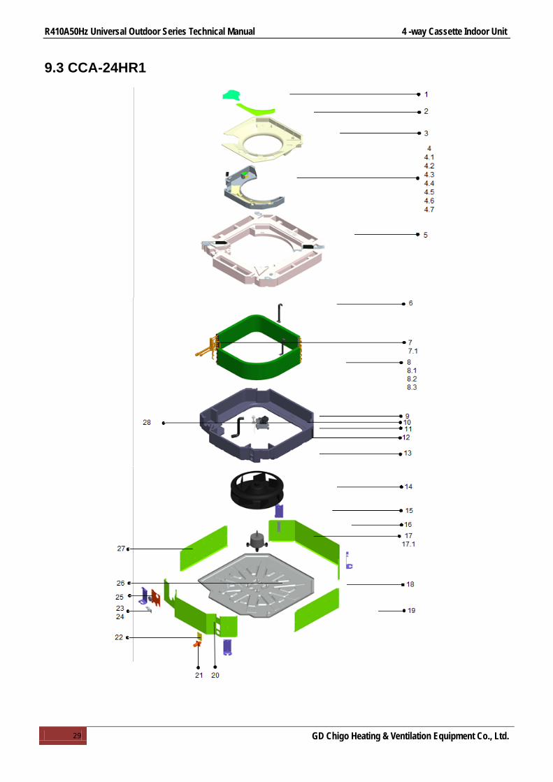
9.3 CCA-24HR1

R410A50Hz Universal Outdoor Series Technical Manual 4 -way Cassette Indoor Unit
30 GD Chigo Heating & Ventilation Equipment Co., Ltd.
No. Part Name Quantity No. Part Name Quantity 1 Warning panel 1 8.3.4 Installation tube for probe 1 2 Circuit diagram panel 1 9 Water pump 1 3 Small wind inlet guide 1 10 Liquid-level sensor 1 4 E-parts components 1 11 Water pump fan motor holder 1 4.1 E-parts box welding assy 1 12 Underlay for water pump support 3 4.2 No.3 groove clamp 1 13 Upper foam 1 4.3 (ROHS)Transformer 1 14 Centrifugal fan 1 4.4 Fan motor capacitor 1 15 Hanger 4 4.5 Terminal (DJ-75W-3PA) 1 16 Rear brattice 1
4.6 Terminal (DJ-75W-5PA) 1 17 Fan motor for indoor unit (YDK-55T-6) 1
4.7 Electric control board for indoor unit 1 17.1 Fan motor foot underlay 1 4.8 E-parts box 1 18 Chassis assy 1 5 Water pan assy 1 19 Right clapboard 1
6 Auxiliary fixing board for evaporator 2 20 Front brattice 1
7 Main fixing board assy 1 21 Discharge pipe joint 1
7.1 Main fixing board for evaporator 1 22 Side maintenance board for water pump 1
8 Evaporator components 1 23 Lower clamp 1 8.1 Rubber insulating pipe 1 24 Upper clamp 1 8.2 Insulating pipe 1 25 Valve panel 1 8.3 Welding parts for evaporator 1 26 Wire board 2 8.3.1 Collecting pipe assy for evaporator 1 27 Left clapboard 1
8.3.2 Distributing pipe assy for evaporator 1 28 Water outlet pipe 1
8.3.3 Evaporator 1

R410A50Hz Universal Outdoor Series Technical Manual 4 -way Cassette Indoor Unit
31 GD Chigo Heating & Ventilation Equipment Co., Ltd.
9.4 CCA-36HR1,CCA-48HR1,CCA-60HR1

R410A50Hz Universal Outdoor Series Technical Manual 4 -way Cassette Indoor Unit
32 GD Chigo Heating & Ventilation Equipment Co., Ltd.
No. Part Name Quantity No. Part Name Quantity
1 E-parts box cover assy 1 1 7.4.3 Collecting pipe assy for evaporator 1
2 E-parts box cover assy 2 1 7.4.4 Distributing pipe assy for evaporator 1
3 E-parts components 1 7.5 Protection rubber 1 3.1 (ROHS)Transformer 1 7.6 Main fixing board assy 1 3.2 Fan motor capacitor 1 8 Upper foam assy 1 3.3 Terminal (DJ-75W-3PA) 1 8.1 Upper foam 1 3.4 Terminal (DJ-75W-5PA) 1 9 pre-installed assy of pump 1 3.5 Electric control board for indoor unit 1 9.1 Water pump fan motor holder 1 3.6 Temperature sensor 1 9.2 Water pump 1 3.7 Temperature sensor 1 9.3 Liquid-level sensor 1
3.8 E-parts box welding base 1 9.4 Underlay for water pump support 3
4 wind inlet guide assy 1 10 fan snap ring 1 4.1 wind inlet guide 1 11 Centrifugal fan 1 5 Water pan assy 1 12 motor pre-installed assy 1
5.1 defrostingtray foam(ROHS) 1 12.1 Fan motor for indoor unit (YDK-75T-6) 1
5.2 water outlet plug 1 13 Rear brattice 1 5.3 foam pendant 2 14 Hanger 4
6 Auxiliary fixing board for evaporator 2 15 Chassis assy 1
7 Evaporator components 1 16 Right clapboard 1 7.1 Insulating pipe 1 17 Front brattice 1 7.2 Rubber insulating pipe 1 18 Discharge pipe joint 1
7.3 Stick cotton 1 19 Side maintenance board for water pump 1
7.4 Welding parts for evaporator 1 20 Valve panel 1 7.4.1 Instalation tube for probe 1 21 Left clapboard 1 7.4.2 evaporator 1

R410A50Hz Universal Outdoor Series Technical Manual 4 -way Cassette Indoor Unit
33 GD Chigo Heating & Ventilation Equipment Co., Ltd.
10.Accessories
Installation Fittings
Name Shape Quantity
Expansible hook
4
Installation hook 4
Installation paper board 1
Bolt M5 4
Tubing & Fittings (optional)
Connecting pipe group 1
Binding tape 1
Soundproof/insulation sheath 2
Drainpipe Fittings
Out-let pipe sheath 1
Tightening band 5
Protect Pipe Fittings (optional)
Wall conduit 1
Wall conduit cover
1
Remote controller
Remote controller
1
Mounting screw(ST2.9×10-C-H) 2
Alkaline dry batteries (AM4) 2
Others Operation&installation instruction manual
1

R410A50Hz Universal Outdoor Series Technical Manual 4 -way Cassette Indoor Unit
34 GD Chigo Heating & Ventilation Equipment Co., Ltd.
11.The Specification of Power
Type CCA-18HR CCB-18HR1 CCA-24HR1
Power Phase 1-phase 1-phase 1-phase
Frequency and Voltage 220-240V, 50Hz
Indoor Unit Power Wiring (mm2) 3×2.5mm2 3×2.5mm2 3×1.0mm2 Indoor/Outdoor
Connecting Wiring (mm2)
Ground Wiring 2.5 mm2 2.5 mm2 1 mm2 Strong Electric
Signal 5×1.5mm2 5×1.5mm2 5×0.75mm2
Type CCA-36HR1 CCA-48HR1 CCA-60HR1
Power Phase 1-phase 1-phase 1-phase
Frequency and Voltage 220-240V, 50Hz
Indoor Unit Power Wiring (mm2) 3×1.0mm2 3×1.0mm2 3×1.0mm2 Indoor/Outdoor
Connecting Wiring (mm2)
Ground Wiring 1 mm2 1 mm2 1 mm2 Strong Electric
Signal 5×0.75mm2 5×0.75mm2 5×0.75mm2

R410A50Hz Universal Outdoor Series Technical Manual 4 -way Cassette Indoor Unit
35 GD Chigo Heating & Ventilation Equipment Co., Ltd.
12.Field Wiring
CCB-18HR1&COU-18HR1 CCA-18HR1&COU18HR1
CCA-24HR1&COU-24HR1
CCA-36HR1&COU-36HR1 CCA-36HR1&COU-36HSR1
CCA-48HR1&COU-48HR1 CCA-60HR1&COU-60HR1

R410A50Hz Universal Outdoor Series Technical Manual 4 -way Cassette Indoor Unit
36 GD Chigo Heating & Ventilation Equipment Co., Ltd.
13.Troubleshooting
Setting Change is Impossible Symptoms Causes Reason and Disposal
The fan speed can not be changed
Check whether the MODE indicated on the display is “AUTO”
When the automatic mode is selected, the air conditioner automatically selects the fan speed
Check whether the MODE indicated on the display is “DEHUNMIDIFICATION”
When dry operation is selected, the air conditioner automatically select the fan speed. The fan speed can be selected during “COOL” and “FAN ONLY”, and “HEAT”
The Transmission Indicator “+””-“ Never Comes On Symptoms Causes Reason and Disposal
The remote control signal is not transmitted even when the ON/OFF button is pushed
Check whether the batteries in the remote controller are exhausted
The remote control signal is not transmitted, because the power supply is off
The Display Never Comes On Symptoms Causes Reason
The TEMP. Indicator does not come on
Check whether the MODE indicated on the display is “FAN ONLY”
The temperature cannot be set during fan only operation
The Display Goes Off Symptoms Causes Reason
The indication on the display disappears af ter a lapse of time
Check whether the timer operation has come to an end when the OFF TIMER is indicated on the display
The air conditioner operation stops since the set time elapsed.
The ON TIMER indicators go off after a lapse of certain time
Check whether the timer operation is started when the ON TIMER is indicated on the display
When the time set to start the air conditioner is reached.the air conditioner will automatically start and the appropriate indicator will go off
The Signal Receiving Tone does Not Sound Symptoms Causes Reason
No receiving tone sounds from the indoor unit even when the ON/OFF button is pushed
Check whether the signal transmitter of remote controller is properly directed to the receiver of the indoor unit when the ON/OFF button is pushed
Direct the signal transmitter of the remote controller to the receiver of the indoor unit , and then repeatly push the ON/OFF button twice
Buttons on the remote controller don’t work Press Reset button

R410A50Hz Universal Outdoor Series Technical Manual 4 -way Cassette Indoor Unit
37 GD Chigo Heating & Ventilation Equipment Co., Ltd.
Fault Code Table No. Type Content LED Flashing Remark
1 Fault Room temperature sensor fault Timing lamp flashing/5Hz
Automatic recovery after the problem resolved
2 Fault Indoor coil temperature sensor fault Running lamp flashing/5Hz
3 Fault Outdoor coil temperature sensor fault Defrosting lamp flashing/5Hz
4 Fault Water full protection Alarm lamp flashing/5Hz
5 Fault Outdoor protection Defrosting lamp and Alarm lamp both flashing/5Hz
6 Fault Communication fault Running lamp and Defrosting lamp both flashing/5Hz
Manual eliminate
7 Fault EEPROM communication fault
Running lamp and Timing lamp both flashing/5Hz
Recovery after interruption of power supply
8 Indication Enforced cooling Running lamp and Alarm lamp both flashing/5Hz
9 Indication Anti- cool air in heating mode Defrosting preheat lamp ON
10 Indication Defrosting Defrosting preheat lamp ON

R410A50Hz Universal Outdoor Series Technical Manual Duct Type Indoor Unit
38 GD Chigo Heating & Ventilation Equipment Co., Ltd.
Duct Type
1.Features .................................................................................. 39
2.Specification ........................................................................... 41
3.Dimensions ............................................................................. 45
4.Service Space .......................................................................... 48
5.Wiring Diagrams ...................................................................... 49
6.Capacity Tables ........................................................................ 54
7.Static Pressure ......................................................................... 61
8.Electric Characteristics ............................................................ 69
9.Sound Levels ........................................................................... 70
10.Accessories ............................................................................ 81
11.The Specification of Wiring .................................................... 82
12.Field Wiring .......................................................................... 83
13.Exploded View ...................................................................... 84
14.Troubleshooting .................................................................... 90

R410A50Hz Universal Outdoor Series Technical Manual Duct Type Indoor Unit
39 GD Chigo Heating & Ventilation Equipment Co., Ltd.
1.Features
Low Static Pressure Duct
Medium Static Pressure Duct
High Static Pressure Duct

R410A50Hz Universal Outdoor Series Technical Manual Duct Type Indoor Unit
40 GD Chigo Heating & Ventilation Equipment Co., Ltd.
1.1 Ultra-thin body design 1.2 Adopting aviation centrifugal fans, and CFD technology design, increasing air-volume and
decreasing noise level, noise level only 29dB(A). 1.3 Three fan speed, meet different requirement. 1.4 30Pa ESP design for the medium static pressure duct type, duct connected installation meet for
different room structure. 1.5 Filter can be taken out easily for clear. Easy maintenance. 1.6 E-box is body-side design, convenient installation and maintenance. 1.7 Two air return type option: air inlet from back is standard and from bottom is optional 1.8 Multi protection and auto-restart function. 1.9 Standard for wired controller, wireless controller for option.

R410A50Hz Universal Outdoor Series Technical Manual Duct Type Indoor Unit
41 GD Chigo Heating & Ventilation Equipment Co., Ltd.
2.Specification
Model CTA-18HR1 CTA-24HR1 CTB-18HR1
Indoor power supply V/Ph/Hz 220~240/1/50 220~240/1/50 220~240/1/50
Cooling
Capacity Btu/h 18000 24000 18000
KW 5.3 7.1 5.3 Input W 70 150 250 Rated current A 0.32 0.68 0.45 EER W/W 2.69 2.78 2.69
Heating
Capacity Btu/h 19800 26400 19800
KW 5.8 7.8 5.8 Input W 70 150 100 Rated current A 0.3 0.7 0.45 COP W/W 3.30 3.47 3.30
Indoor fan motor
Model YSK-110-35P-4P3H95 YSK-110-50P-4P3H95 YSK110-90F-4P3H105 Input W 70 150 250 Capacitor μF 1.8 3 5 Speed(Hi/Med/Lo) r/min 1170/960/800 1170/990/850 1100/900/750
Indoor coil
Number of rows 3 3 3 Tube pitch x row pitch mm 21×12.7 21×12.7 22×19.05 Fin spacing mm 1.6 1.6 1.7 Fin type Hydrophilic Hydrophilic Hydrophilic Tube outside dia. and type mm
Ф7 Ф7 Ф7.94 inner grooved inner grooved inner grooved
Coil size(W×H×D) mm 900×231×38.1 1222×231×38.1 900×240×57.15 Number of circuits 4 5 6
Indoor air flow(Hi/Med/Lo) m3/h 730/600/500 1020/860/740 1010/840/700 Static Pressure Pa 30 30 70 Indoor noise level(Hi/Med/Lo) dB(A) 42/31/26 43/32/28 38/36/34
Indoor unit Dimension(W×H×D) mm 1204×181×510 1532×181×510 1189×260×663 Packing(W×H×D) mm 1330×250×605 1650×250×605 1255×330×730 Net/Gross weight kg 21/25 26/30 32/36
Refrigerant type R410A R410A R410A Refrigerant piping Liquid side/Gas side mm Φ6.35/Φ12.7 Φ9.52/Φ15.88 Φ6.35/Φ12.7
Drainage pipe mm 30 30 30
Connection wiring
Power Supply From indoor unit From outdoor unit From outdoor unit Indoor power wiring mm2 2.5 1.0 2.5 Signal wiring mm2 0.75 1.5 0.75
Controller Standard for wired controller(remote controller for option) Operation temp °C 16~32 16~32 16~32 Ambient temp °C -7~43 -7~43 -7~43 Application area m2 20-35 28~50 28-50 Stuffing Quantity (20'/40'/40'HQ) 115/250/320 90/190/255 75/165/189 Notes: 1. Nominal cooling capacities are based on the following conditions:
Indoor temp: 27°CDB, 19°CWB; Outdoor temp: 35°CDB; Equivalent ref. Piping: 7.5m(horizontal) 2. Nominal heating capacities are based on the following conditions:
Indoor temp: 20°CDB; Outdoor temp: 7°CDB, 6°CWB; Equivalent ref. Piping: 7.5m(horizontal) 3. Actual noise level may differ, depending on the room structure, etc, since these noise values are from an anechoic room.
R410A50Hz Universal Outdoor Series Technical Manual Duct Type Indoor Unit
42 GD Chigo Heating & Ventilation Equipment Co., Ltd.
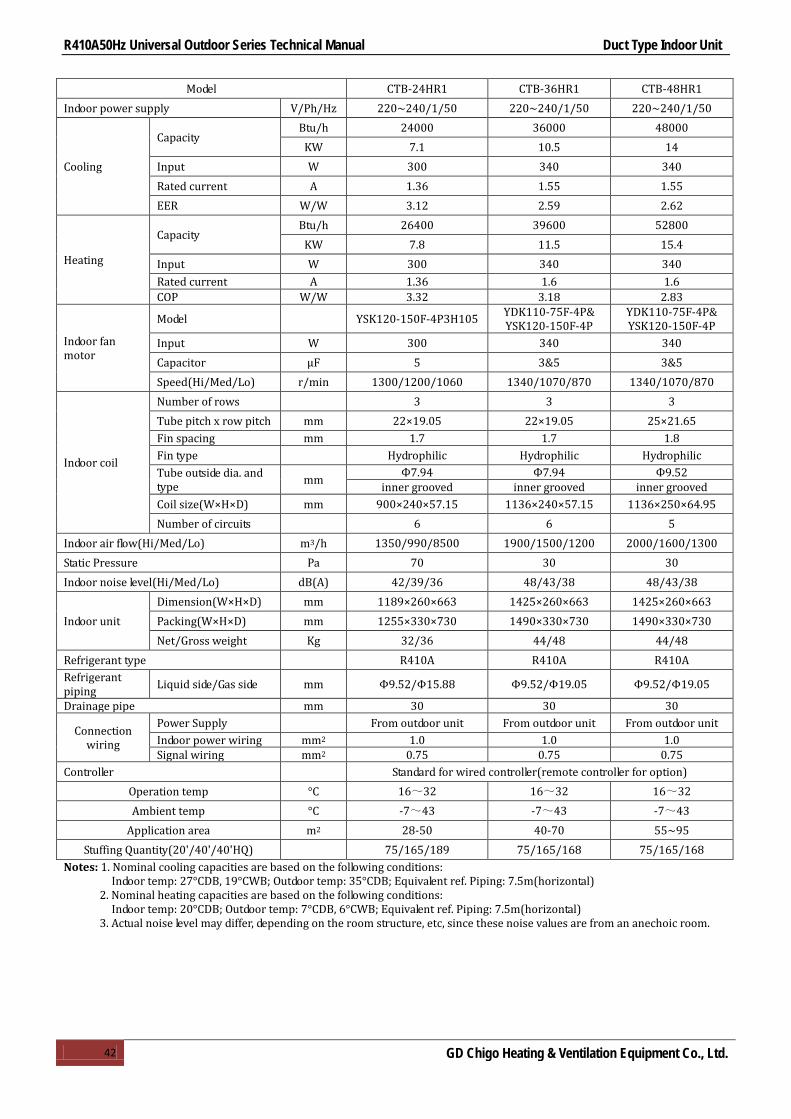
Model CTB-24HR1 CTB-36HR1 CTB-48HR1
Indoor power supply V/Ph/Hz 220~240/1/50 220~240/1/50 220~240/1/50
Cooling
Capacity Btu/h 24000 36000 48000
KW 7.1 10.5 14 Input W 300 340 340 Rated current A 1.36 1.55 1.55 EER W/W 3.12 2.59 2.62
Heating
Capacity Btu/h 26400 39600 52800
KW 7.8 11.5 15.4 Input W 300 340 340 Rated current A 1.36 1.6 1.6 COP W/W 3.32 3.18 2.83
Indoor fan motor
Model YSK120-150F-4P3H105 YDK110-75F-4P& YSK120-150F-4P
YDK110-75F-4P& YSK120-150F-4P
Input W 300 340 340 Capacitor μF 5 3&5 3&5 Speed(Hi/Med/Lo) r/min 1300/1200/1060 1340/1070/870 1340/1070/870
Indoor coil
Number of rows 3 3 3 Tube pitch x row pitch mm 22×19.05 22×19.05 25×21.65 Fin spacing mm 1.7 1.7 1.8 Fin type Hydrophilic Hydrophilic Hydrophilic Tube outside dia. and type mm Ф7.94 Ф7.94 Ф9.52
inner grooved inner grooved inner grooved Coil size(W×H×D) mm 900×240×57.15 1136×240×57.15 1136×250×64.95 Number of circuits 6 6 5
Indoor air flow(Hi/Med/Lo) m3/h 1350/990/8500 1900/1500/1200 2000/1600/1300 Static Pressure Pa 70 30 30 Indoor noise level(Hi/Med/Lo) dB(A) 42/39/36 48/43/38 48/43/38
Indoor unit Dimension(W×H×D) mm 1189×260×663 1425×260×663 1425×260×663 Packing(W×H×D) mm 1255×330×730 1490×330×730 1490×330×730 Net/Gross weight Kg 32/36 44/48 44/48
Refrigerant type R410A R410A R410A Refrigerant piping Liquid side/Gas side mm Φ9.52/Φ15.88 Φ9.52/Φ19.05 Φ9.52/Φ19.05
Drainage pipe mm 30 30 30
Connection wiring
Power Supply From outdoor unit From outdoor unit From outdoor unit Indoor power wiring mm2 1.0 1.0 1.0 Signal wiring mm2 0.75 0.75 0.75
Controller Standard for wired controller(remote controller for option) Operation temp °C 16~32 16~32 16~32 Ambient temp °C -7~43 -7~43 -7~43
Application area m2 28-50 40-70 55~95 Stuffing Quantity(20'/40'/40'HQ) 75/165/189 75/165/168 75/165/168
Notes: 1. Nominal cooling capacities are based on the following conditions: Indoor temp: 27°CDB, 19°CWB; Outdoor temp: 35°CDB; Equivalent ref. Piping: 7.5m(horizontal)
2. Nominal heating capacities are based on the following conditions: Indoor temp: 20°CDB; Outdoor temp: 7°CDB, 6°CWB; Equivalent ref. Piping: 7.5m(horizontal)
3. Actual noise level may differ, depending on the room structure, etc, since these noise values are from an anechoic room.
R410A50Hz Universal Outdoor Series Technical Manual Duct Type Indoor Unit
43 GD Chigo Heating & Ventilation Equipment Co., Ltd.
Notes: 1. Nominal cooling capacities are based on the following conditions: Indoor temp: 27°CDB, 19°CWB; Outdoor temp: 35°CDB; Equivalent ref. Piping: 7.5m(horizontal)
2. Nominal heating capacities are based on the following conditions: Indoor temp: 20°CDB; Outdoor temp: 7°CDB, 6°CWB; Equivalent ref. Piping: 7.5m(horizontal)
3. Actual noise level may differ, depending on the room structure, etc, since these noise values are from an anechoic room.
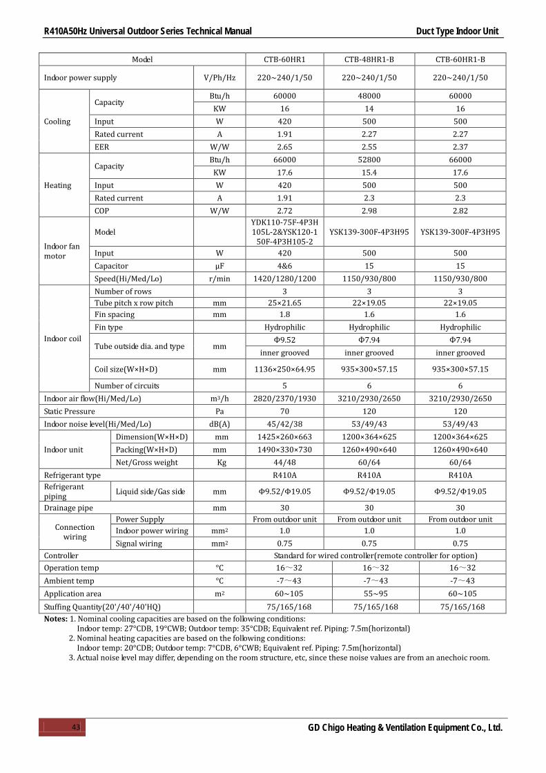
Model CTB-60HR1 CTB-48HR1-B CTB-60HR1-B
Indoor power supply V/Ph/Hz 220~240/1/50 220~240/1/50 220~240/1/50
Cooling
Capacity Btu/h 60000 48000 60000
KW 16 14 16 Input W 420 500 500 Rated current A 1.91 2.27 2.27 EER W/W 2.65 2.55 2.37
Heating
Capacity Btu/h 66000 52800 66000
KW 17.6 15.4 17.6 Input W 420 500 500 Rated current A 1.91 2.3 2.3 COP W/W 2.72 2.98 2.82
Indoor fan motor
Model YDK110-75F-4P3H105L-2&YSK120-1
50F-4P3H105-2 YSK139-300F-4P3H95 YSK139-300F-4P3H95
Input W 420 500 500 Capacitor μF 4&6 15 15 Speed(Hi/Med/Lo) r/min 1420/1280/1200 1150/930/800 1150/930/800
Indoor coil
Number of rows 3 3 3 Tube pitch x row pitch mm 25×21.65 22×19.05 22×19.05 Fin spacing mm 1.8 1.6 1.6 Fin type Hydrophilic Hydrophilic Hydrophilic
Tube outside dia. and type mm Ф9.52 Ф7.94 Ф7.94
inner grooved inner grooved inner grooved
Coil size(W×H×D) mm 1136×250×64.95 935×300×57.15 935×300×57.15
Number of circuits 5 6 6 Indoor air flow(Hi/Med/Lo) m3/h 2820/2370/1930 3210/2930/2650 3210/2930/2650 Static Pressure Pa 70 120 120 Indoor noise level(Hi/Med/Lo) dB(A) 45/42/38 53/49/43 53/49/43
Indoor unit Dimension(W×H×D) mm 1425×260×663 1200×364×625 1200×364×625 Packing(W×H×D) mm 1490×330×730 1260×490×640 1260×490×640 Net/Gross weight Kg 44/48 60/64 60/64
Refrigerant type R410A R410A R410A Refrigerant piping Liquid side/Gas side mm Φ9.52/Φ19.05 Φ9.52/Φ19.05 Φ9.52/Φ19.05
Drainage pipe mm 30 30 30
Connection wiring
Power Supply From outdoor unit From outdoor unit From outdoor unit Indoor power wiring mm2 1.0 1.0 1.0 Signal wiring mm2 0.75 0.75 0.75
Controller Standard for wired controller(remote controller for option) Operation temp °C 16~32 16~32 16~32 Ambient temp °C -7~43 -7~43 -7~43 Application area m2 60~105 55~95 60~105 Stuffing Quantity(20'/40'/40'HQ) 75/165/168 75/165/168 75/165/168

R410A50Hz Universal Outdoor Series Technical Manual Duct Type Indoor Unit
44 GD Chigo Heating & Ventilation Equipment Co., Ltd.
Notes: 1. Nominal cooling capacities are based on the following conditions: Indoor temp: 27°CDB, 19°CWB; Outdoor temp: 35°CDB; Equivalent ref. Piping: 7.5m(horizontal)
2. Nominal heating capacities are based on the following conditions: Indoor temp: 20°CDB; Outdoor temp: 7°CDB, 6°CWB; Equivalent ref. Piping: 7.5m(horizontal)
3. Actual noise level may differ, depending on the room structure, etc, since these noise values are from an anechoic room.
Model CTH-48HR1 CTH-60HR1
Indoor power supply V/Ph/Hz 220~240/1/50 220~240/1/50
Cooling
Capacity Btu/h 48000 60000
KW 14 16 Input W 500 500 Rated current A 2.27 2.27 EER W/W 2.55 2.58
Heating
Capacity Btu/h 52800 66000
KW 15.4 16.6 Input W 500 500 Rated current A 2.3 2.3 COP W/W 2.77 2.65
Indoor fan motor
Model YSK139-300F-4P3H95 YSK139-300F-4P3H95
Input W 500 500 Capacitor μF 15 15 Speed(Hi/Med/Lo) r/min 1150/930/800 1150/930/800
Indoor coil
Number of rows 3 3
Tube pitch x row pitch mm 22×19.05 22×19.05
Fin spacing mm 1.6 1.6 Fin type Hydrophilic Hydrophilic
Tube outside dia. and type mm Ф7.94 Ф7.94
inner grooved inner grooved
Coil size(W×H×D) mm 935×300×57.15 935×300×57.15
Number of circuits 6 6 Indoor air flow(Hi/Med/Lo) m3/h 2300/2100/1900 2300/2100/1900 Static Pressure Pa 120 120 Indoor noise level(Hi/Med/Lo) dB(A) 55/51/47 55/51/47
Indoor unit Dimension(W×H×D) mm 1200×364×625 1200×364×625 Packing(W×H×D) mm 1260×490×640 1260×490×640 Net/Gross weight Kg 60/64 60/64
Refrigerant type R410A R410A Refrigerant piping Liquid side/Gas side mm Φ9.52/Φ19.05 Φ9.52/Φ19.05
Drainage pipe mm 30 30
Connection wiring
Power Supply From outdoor unit From outdoor unit
Indoor power wiring mm2 1.0 1.0 Signal wiring mm2 0.75 0.75
Controller Standard for wired controller(remote controller for option) Operation temp °C 16~32 16~32 Ambient temp °C -7~43 -7~43 Application area m2 55~95 60~105 Stuffing Quantity(20'/40'/40'HQ) 75/165/168 75/165/168

R410A50Hz Universal Outdoor Series Technical Manual Duct Type Indoor Unit
45 GD Chigo Heating & Ventilation Equipment Co., Ltd.
3.Dimensions
3.1 CTA-18HR1
3.2 CTA-24HR1

R410A50Hz Universal Outdoor Series Technical Manual Duct Type Indoor Unit
46 GD Chigo Heating & Ventilation Equipment Co., Ltd.
3.3 CTB-18HR1, CTB-24HR1
3.4 CTB-36HR1, CTB-48HR1, CTB-60HR1

R410A50Hz Universal Outdoor Series Technical Manual Duct Type Indoor Unit
47 GD Chigo Heating & Ventilation Equipment Co., Ltd.
3.5 CTB-48HR1-B, CTB-60HR1-B, CTH-48HR1, CTH-60HR1
R410A50Hz Universal Outdoor Series Technical Manual Duct Type Indoor Unit
48 GD Chigo Heating & Ventilation Equipment Co., Ltd.
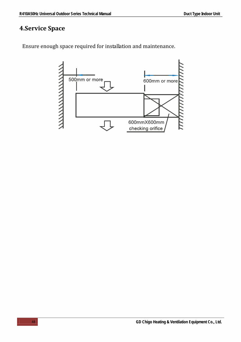
4.Service Space
Ensure enough space required for installation and maintenance.

R410A50Hz Universal Outdoor Series Technical Manual Duct Type Indoor Unit
49 GD Chigo Heating & Ventilation Equipment Co., Ltd.
5.Wiring Diagrams
5.1 CTA-18HR1, CTB-18HR1
BL
LCD
scr
een
Roo
m S
enso
r
Con
trolle
r
5C
N12
0
CN
4TC
NTR
DR
DB
L
Tran
sfor
mer
RD
3O
R4
Out
door
Uni
t
BK
NY
E/G
N
GY
1XT L
N Indo
CO
MP
RE
SSO
RY
E/G
N
Con
nect
Out
door
BK
FAN
YE/
GN
BL
YE
BRW
HLink
er
( WH)
Link
er
( BK)
BL
YE
BR
WH
Link
er
( WH)
PIP
E S
EN
SO
R
OU
TDO
OR
FA
N4-
LOU
VE
R M
OTO
R
2
Out
door
Pip
e Se
sor
3 41 2
52C
CN
22
CN
B
CN
21
Pip
e S
esor
Room sC
N20
L
Ext
erio
r Fee
dbac
k
NO
CO
MM
FIM
FI-2

R410A50Hz Universal Outdoor Series Technical Manual Duct Type Indoor Unit
50 GD Chigo Heating & Ventilation Equipment Co., Ltd.
5.2 CTA-24HR1
GY
LCD
scr
een
Roo
m S
enso
r
Con
trolle
r
5C
N12
0
CN
4TC
NTR
DR
DB
L
Tran
sfor
mer
RD
3B
R4
Out
door
Uni
t
BK
NY
E/G
N
OR
1XT L
N Indo
CO
MP
RE
SS
OR
BL
Con
nect
Out
door
FAN
YE
/GN
BLY
EB
RW
H
Link
er
( WH)
Link
er
( BK)
BL
YE
BR
WH
Link
er
( WH)
PIP
E S
EN
SO
R
OU
TDO
OR
FA
N4-
LOU
VE
R M
OTO
R
2
Out
door
Pip
e S
esor
3 41 2
52C
CN
22
CN
B
CN
21
Pip
e S
esor
Room s
CN
20
L5
5
BK
Ext
erio
r Fee
dbac
k
NO
CO
M1
MFI
MFI
-2
R410A50Hz Universal Outdoor Series Technical Manual Duct Type Indoor Unit
51 GD Chigo Heating & Ventilation Equipment Co., Ltd.
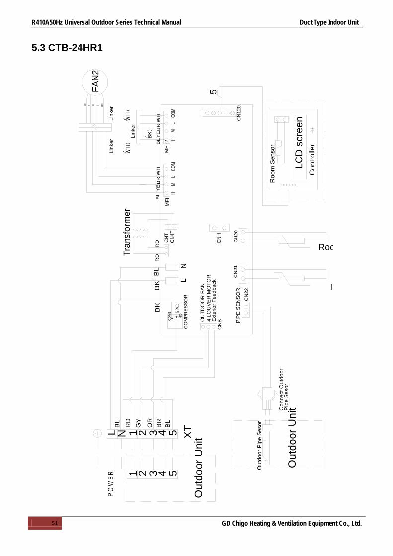
5.3 CTB-24HR1
5
BL
N XTL
RD
RD
RD
OR
GY
BL
FAN
2
BK
52C
CN
TC
N4T
MFI
MFI
-2
CN
120
CN
B
CN
22
CN
21
CN
H
51 432B
R BL
51 432
LN
Con
nect
Out
door
Pip
e S
esor
Out
door
Pip
e S
esor
Out
door
Uni
t
Out
door
Uni
tO
UTD
OO
R F
AN
4-LO
UV
ER
MO
TOR
PIP
E S
EN
SO
R I
Tran
sfor
mer
Roo
m S
enso
r
LCD
scr
een
Con
trolle
r
BL
YE
BR
WH
BLY
EB
RW
H
Link
er
( BK)
Link
er
( WH)
Link
er
( WH)
CO
MP
RE
SS
OR
Ext
erio
r Fee
dbac
k
CN
20
Roo
CO
M1
NO
BK

R410A50Hz Universal Outdoor Series Technical Manual Duct Type Indoor Unit
52 GD Chigo Heating & Ventilation Equipment Co., Ltd.
5.4 CTB-36HR1, CTB-48HR1, CTB-60HR1
5
BL
BK
N XTL
RD
RD
RD
OR
GY
BL
FAN
2
FAN
1
BK
52C
CN
TC
N4T
MF1
MF2
CN
120
CN
B
CN
22
CN
21
CN
H
51 432B
RB
L51 432
LN
Con
nect
Out
door
Pip
e S
esor
Out
door
Pip
e S
esor
Out
door
Uni
t
Out
door
Uni
t
P O
W E
R
OU
TDO
OR
FA
N4-
LOU
VE
R M
OTO
R
PIP
E S
EN
SO
RIn
Tran
sfor
mer
Roo
m S
enso
r
LCD
scr
een
Con
trolle
r
BL
YE
BRW
HB
LYE
BR
WH
Link
er
( BK)
Link
er
( BK)
Link
er
( WH)
Link
er
( WH)
Link
er
( WH)
Link
er
( WH)
CO
MP
RE
SS
OR
Ext
erio
r Fee
dbac
k
CN
20
Roo
BL
YE
BR
WH

R410A50Hz Universal Outdoor Series Technical Manual Duct Type Indoor Unit
53 GD Chigo Heating & Ventilation Equipment Co., Ltd.
5.5 CTB-48HR1-B, CTB-60HR1-B, CTH-48HR1, CTH-60HR1
5
BLBK
N XTL
RD
RD
RD
OR
GY
BL
FAN
BK
52C
CN
TC
N4T
MFI
MFI
-2
CN
120
CN
B
CN
22
CN
21
CN
H
51 432B
RBL
51 432
LN
Con
nect
Out
door
Pip
e S
esor
Out
door
Pip
e S
esor
Out
door
Uni
t
Out
door
Uni
tO
UTD
OO
R F
AN
4-LO
UV
ER
MO
TOR
PIP
E S
EN
SO
R
In
Tran
sfor
mer
Roo
m S
enso
r
LCD
scr
een
Con
trolle
r
CO
MP
RE
SS
OR
Ext
erio
r Fee
dbac
k
CN
20
Roo

R410A50Hz Universal Outdoor Series Technical Manual Duct Type Indoor Unit
54 GD Chigo Heating & Ventilation Equipment Co., Ltd.
6.Capacity Tables
Cooling 6.1 CTA-18HR1
MODEL CTA-18HR1 COOLING OUTDOOR TEMPERATURE DRY
Indoor Conditions 21ºC 25ºC 30ºC 35ºC 40ºC 45ºC
21ºC DB 15ºC WB
Total capacity kW 5.19 4.92 4.76 4.48 4.28 4.18 Sensitive capacity kW 4.12 3.93 3.81 3.56 3.41 3.31 Input kW. 1.15 1.29 1.47 1.61 1.8 1.96
24ºC DB 17ºC WB
Total capacity kW 5.67 5.39 5.27 4.91 4.71 4.58 Sensitive capacity kW 4.5 4.31 4.15 3.93 3.77 3.62 Input kW. 1.21 1.36 1.54 1.73 1.91 2.07
27ºC DB 19ºC WB
Total capacity kW 6.13 5.85 5.64 5.3 5.1 4.94 Sensitive capacity kW 4.82 4.68 4.5 4.13 4.09 3.96 Input kW. 1.25 1.48 1.62 1.79 2.01 2.18
32ºC DB 23ºC WB
Total capacity kW 7.1 6.73 6.5 6.15 5.9 5.72 Sensitive capacity kW 5.63 5.39 5.21 4.91 4.87 4.54 Input kW. 1.48 1.68 1.87 2.1 2.32 2.54
6.2 CTA-24HR1
MODEL CTA-24HR1 COOLING OUTDOOR TEMPERATURE DRY
Indoor Conditions 21ºC 25ºC 30ºC 35ºC 40ºC 45ºC
21ºC DB 15ºC WB
Total capacity kW 6.87 6.54 6.32 5.94 5.75 5.53 Sensitive capacity kW 5.51 5.24 5.03 4.75 4.55 4.45 Input kW. 5.49 5.24 5.03 4.76 4.57 4.45
24ºC DB 17ºC WB
Total capacity kW 7.53 7.17 6.93 6.51 6.28 6.05 Sensitive capacity kW 6.02 5.76 5.52 5.22 5.03 4.84 Input kW. 1.67 1.90 2.16 2.36 2.61 2.86
27ºC DB 19ºC WB
Total capacity kW 8.18 7.80 7.52 7.11 6.84 6.61 Sensitive capacity kW 6.53 6.24 6.02 5.66 5.44 5.27 Input kW. 1.74 2.00 2.23 2.52 2.73 3.02
32ºC DB 23ºC WB
Total capacity kW 9.38 8.97 8.63 8.14 7.82 7.56 Sensitive capacity kW 7.53 7.17 6.921 6.51 6.25 6.04 Input kW. 2.02 2.32 2.61 2.87 3.16 3.44
6.3 CTB-18HR1
MODEL CTB-18HR1 COOLING OUTDOOR TEMPERATURE DRY
Indoor Conditions 21ºC 25ºC 30ºC 35ºC 40ºC 45ºC
21ºC DB 15ºC WB
Total capacity kW 5.34 5.11 4.98 4.72 4.44 4.32 Sensitive capacity kW 4.33 4.19 3.98 3.73 3.55 3.41 Input kW. 1.30 1.49 1.57 1.65 1.92 2.18
24ºC DB 17ºC WB
Total capacity kW 5.92 5.54 5.47 5.17 4.95 4.88 Sensitive capacity kW 4.78 4.61 4.36 4.13 3.97 3.87 Input kW. 1.11 1.38 1.74 1.83 2.13 2.37
27ºC DB 19ºC WB
Total capacity kW 6.43 6.28 6.01 5.83 5.61 5.34 Sensitive capacity kW 5.03 4.78 4.54 4.13 3.98 3.76 Input kW. 1.20 1.58 1.73 1.90 2.21 2.48
32ºC DB 23ºC WB
Total capacity kW 7.3 6.93 6.71 6.45 6.15 5.92 Sensitive capacity kW 5.83 5.58 5.41 5.11 4.97 4.64 Input kW. 1.58 1.72 1.89 2.23 2.45 2.60

R410A50Hz Universal Outdoor Series Technical Manual Duct Type Indoor Unit
55 GD Chigo Heating & Ventilation Equipment Co., Ltd.
6.4 CTB-24HR1
MODEL CTB-24HR1 COOLING OUTDOOR TEMPERATURE DRY
Indoor Conditions 21ºC 25ºC 30ºC 35ºC 40ºC 45ºC
21ºC DB 15ºC WB
Total capacity kW 6.84 6.55 6.31 5.95 5.72 5.53 Sensitive capacity kW 5.47 5.24 5.04 4.76 4.57 4.43 Input kW. 1.57 1.79 2.01 2.25 2.46 2.7
24ºC DB 17ºC WB
Total capacity kW 7.52 7.18 6.91 6.52 6.28 6.06 Sensitive capacity kW 6 5.73 5.53 5.22 5.03 4.87 Input kW. 1.65 1.9 2.13 2.37 2.61 2.88
27ºC DB 19ºC WB
Total capacity kW 8.16 7.79 7.54 7.1 6.83 6.58 Sensitive capacity kW 6.54 6.22 6.01 5.66 5.43 5.27 Input kW. 1.75 2 2.24 2.49 2.75 3
32ºC DB 23ºC WB
Total capacity kW 9.37 8.96 8.64 8.15 7.83 7.58 Sensitive capacity kW 7.5 7.18 6.91 6.52 6.25 6.06 Input kW. 2.01 2.29 2.59 2.87 3.16 3.44
6.5 CTB-36HR1
MODEL CTB-36HR1 COOLING OUTDOOR TEMPERATURE DRY
Indoor Conditions 21ºC 25ºC 30ºC 35ºC 40ºC 45ºC
21ºC DB 15ºC WB
Total capacity kW 10.12 9.68 9.33 8.8 8.45 8.18 Sensitive capacity kW 8.07 7.74 7.45 7.04 6.76 6.53 Input kW. 2.34 2.72 3.03 3.36 3.68 4.02
24ºC DB 17ºC WB
Total capacity kW 11.09 10.61 10.22 9.64 9.26 8.96 Sensitive capacity kW 8.87 8.48 8.16 7.71 7.4 7.16 Input kW. 2.45 2.83 3.18 3.54 3.93 4.27
27ºC DB 19ºC WB
Total capacity kW 12.05 11.53 11.09 10.5 10.07 9.75 Sensitive capacity kW 9.63 9.22 8.87 8.38 8.05 7.78 Input kW. 2.65 3.01 3.36 3.83 4.11 4.48
32ºC DB 23ºC WB
Total capacity kW 13.87 13.26 12.78 12.06 11.57 11.21 Sensitive capacity kW 11.09 10.61 10.22 9.64 9.26 8.96 Input kW. 3 3.43 3.86 4.3 4.72 5.16
6.6 CTB-48HR1
MODEL CTB-48HR1 COOLING OUTDOOR TEMPERATURE DRY
Indoor Conditions 21ºC 25ºC 30ºC 35ºC 40ºC 45ºC
21ºC DB 15ºC WB
Total capacity kW 13.51 12.92 12.45 11.75 11.27 10.95 Sensitive capacity kW 10.8 10.33 9.96 9.38 9.01 8.73 Input kW. 3.06 3.36 3.9 4.31 4.71 5.19
24ºC DB 17ºC WB
Total capacity kW 14.79 14.14 13.64 12.89 12.34 11.96 Sensitive capacity kW 11.81 11.31 10.91 10.31 9.87 9.57 Input kW. 3.21 3.55 4.11 4.55 4.98 5.44
27ºC DB 19ºC WB
Total capacity kW 16.09 15.37 14.82 14.00 13.43 13.01 Sensitive capacity kW 12.86 12.41 11.85 11.21 10.72 10.44 Input kW. 3.38 3.86 4.3 5.16 5.25 5.72
32ºC DB 23ºC WB
Total capacity kW 18.5 17.72 17.05 16.08 15.44 14.96 Sensitive capacity kW 14.79 14.16 13.63 12.86 12.33 11.93 Input kW. 3.86 4.41 4.94 5.49 5.99 6.58

R410A50Hz Universal Outdoor Series Technical Manual Duct Type Indoor Unit
56 GD Chigo Heating & Ventilation Equipment Co., Ltd.
6.7 CTB-60HR1
MODEL CTB-60HR1 COOLING OUTDOOR TEMPERATURE DRY
Indoor Conditions 21ºC 25ºC 30ºC 35ºC 40ºC 45ºC
21ºC DB 15ºC WB
Total capacity kW 15.45 14.79 14.25 12.11 12.91 12.5 Sensitive capacity kW 12.37 11.83 11.4 10.75 10.32 10.02 Input kW. 3.75 4.3 4.84 5.36 5.92 6.44
24ºC DB 17ºC WB
Total capacity kW 16.93 16.19 15.61 14.72 13.13 13.71 Sensitive capacity kW 13.54 12.95 12.48 11.78 11.3 10.97 Input kW. 3.95 4.54 5.11 5.66 6.23 6.82
27ºC DB 19ºC WB
Total capacity kW 18.42 17.6 16.98 16 15.36 14.88 Sensitive capacity kW 14.72 14.1 13.58 12.8 12.3 11.91 Input kW. 4.16 4.78 5.36 5.97 6.57 7.18
32ºC DB 23ºC WB
Total capacity kW 21.16 20.24 19.5 18.42 17.67 17.12 Sensitive capacity kW 16.92 16.19 15.61 14.74 14.13 13.7 Input kW. 4.81 5.48 6.17 6.88 7.55 8.24
6.8 CTB-48HR1-B
MODEL CTB-48HR1-B COOLING OUTDOOR TEMPERATURE DRY
Indoor Conditions 21ºC 25ºC 30ºC 35ºC 40ºC 45ºC
21ºC DB 15ºC WB
Total capacity kW 13.87 13.23 12.92 11.86 11.49 10.99 Sensitive capacity kW 11.03 10.75 10.23 9.71 9.36 8.98
Input kW. 2.86 3.18 3.61 4.13 4.32 4.66
24ºC DB 17ºC WB
Total capacity kW 15.82 15.27 14.85 13.68 13.31 12.98 Sensitive capacity kW 12.06 11.83 11.12 10.55 10.17 9.89
Input kW. 3.04 3.33 3.89 4.11 4.47 4.98
27ºC DB 19ºC WB
Total capacity kW 16.34 15.89 15.04 14.80 13.92 13.42 Sensitive capacity kW 12.88 12.32 11.87 11.20 10.75 10.42
Input kW. 3.29 3.76 4.23 4.70 5.17 5.64
32ºC DB 23ºC WB
Total capacity kW 18.52 17.71 17.07 16.10 15.46 14.97 Sensitive capacity kW 14.81 14.17 13.65 12.88 12.36 11.98
Input kW. 3.68 4.21 4.76 5.04 5.65 6.04
6.9 CTB-60HR1-B
MODEL CTB-60HR1-B COOLING OUTDOOR TEMPERATURE DRY
Indoor Conditions 21ºC 25ºC 30ºC 35ºC 40ºC 45ºC
21ºC DB 15ºC WB
Total capacity kW 15.47 14.73 14.28 12.21 12.91 12.5 Sensitive capacity kW 12.37 11.83 11.4 10.75 10.32 10.02 Input kW. 3.73 4.34 4.84 5.36 5.92 6.44
24ºC DB 17ºC WB
Total capacity kW 16.93 16.17 15.53 14.70 13.11 13.75 Sensitive capacity kW 13.74 12.91 12.43 11.74 11.34 10.67 Input kW. 3.65 4.34 5.11 5.64 6.24 6.81
27ºC DB 19ºC WB
Total capacity kW 17.25 16.6 16.2 16.2 15.34 14.83 Sensitive capacity kW 14.72 14.11 13.54 12.7 12.3 11.81 Input kW. 4.17 4.75 5.36 5.97 6.54 7.18
32ºC DB 23ºC WB
Total capacity kW 21.14 20.22 19.5 18.36 17.67 17.12 Sensitive capacity kW 16.92 16.17 15.61 14.71 14.13 13.7 Input kW. 4.91 5.43 6.17 6.90 7.55 8.23

R410A50Hz Universal Outdoor Series Technical Manual Duct Type Indoor Unit
57 GD Chigo Heating & Ventilation Equipment Co., Ltd.
6.10 CTH-48HR1
MODEL CTH-48HR1 COOLING OUTDOOR TEMPERATURE DRY
Indoor Conditions 21ºC 25ºC 30ºC 35ºC 40ºC 45ºC
21ºC DB 15ºC WB
Total capacity kW 13.52 12.94 12.47 11.76 11.29 10.94 Sensitive capacity kW 10.82 10.35 9.97 9.41 9.03 8.75
Input kW. 2.96 3.38 3.81 4.23 4.65 5.08
24ºC DB 17ºC WB
Total capacity kW 14.81 14.17 13.65 12.88 12.36 11.98 Sensitive capacity kW 11.85 11.33 10.92 10.30 9.89 9.58
Input kW. 3.13 3.57 4.02 4.47 4.91 5.36
27ºC DB 19ºC WB
Total capacity kW 16.10 15.40 14.84 14.00 13.44 13.02 Sensitive capacity kW 12.88 12.32 11.87 11.20 10.75 10.42
Input kW. 3.29 3.76 4.23 4.70 5.17 5.64
32ºC DB 23ºC WB
Total capacity kW 18.52 17.71 17.07 16.10 15.46 14.97 Sensitive capacity kW 14.81 14.17 13.65 12.88 12.36 11.98
Input kW. 3.78 4.32 4.86 5.41 5.95 6.49
6.11 CTH-60HR1
MODEL CTH-60HR1 COOLING OUTDOOR TEMPERATURE DRY
Indoor Conditions 21ºC 25ºC 30ºC 35ºC 40ºC 45ºC
21ºC DB 15ºC WB
Total capacity kW 15.47 14.73 14.28 12.21 12.91 12.5 Sensitive capacity kW 12.37 11.83 11.4 10.75 10.32 10.02 Input kW. 3.73 4.34 4.84 5.36 5.92 6.44
24ºC DB 17ºC WB
Total capacity kW 16.93 16.17 15.53 14.70 13.11 13.75 Sensitive capacity kW 13.74 12.91 12.43 11.74 11.34 10.67 Input kW. 3.65 4.34 5.11 5.64 6.24 6.81
27ºC DB 19ºC WB
Total capacity kW 17.25 16.6 16.2 16.2 15.34 14.83 Sensitive capacity kW 14.72 14.11 13.54 12.7 12.3 11.81 Input kW. 4.17 4.75 5.36 5.97 6.54 7.18
32ºC DB 23ºC WB
Total capacity kW 21.14 20.22 19.5 18.36 17.67 17.12 Sensitive capacity kW 16.92 16.17 15.61 14.71 14.13 13.7 Input kW. 4.91 5.43 6.17 6.90 7.55 8.23

R410A50Hz Universal Outdoor Series Technical Manual Duct Type Indoor Unit
58 GD Chigo Heating & Ventilation Equipment Co., Ltd.
Heating 6.12 CTA-18HR1
MODEL CTA-18HR1 HEATING OUTDOOR CONDITIONS
Indoor Conditions 24ºC DB 18ºC WB
12ºC DB 11ºC WB
7ºC DB 6ºC WB
4ºC DB 3ºC WB
0ºC DB -1ºC WB
-5ºC DB -6ºC WB
-7ºC DB -8ºC WB
15ºC Capacity kW 10.15 8.14 6.75 6.11 5.69 5.08 4.75 Input kW. 3.15 2.48 2.07 1.93 1.87 1.8 1.68
18ºC Capacity kW 9.56 7.68 6.36 5.75 5.4351 4.78 4.49 Input kW. 2.98 2.35 1.94 1.83 1.76 1.66 1.58
20ºC Capacity kW 8.92 7.05 5.8 5.28 5.02 4.42 4.12
Input kW. 2.75 2.18 1.71 1.68 1.63 1.53 1.44
22ºC Capacity kW 8.12 6.48 5.43 4.87 4.6 4.06 3.78 Input kW. 2.48 1.98 1.64 16 1.51 1.41 1.32
27ºC Capacity kW 7.12 5.62 4.68 4.21 4.02 3.51 3.28 Input kW. 2.14 1.68 1.43 1.34 1.27 1.19 1.16
6.13 CTA-24HR1
MODEL CTA-24HR1 HEATING OUTDOOR CONDITIONS
Indoor Conditions 24ºC DB 18ºC WB
12ºC DB 11ºC WB
7ºC DB 6ºC WB
4ºC DB 3ºC WB
0ºC DB -1ºC WB
-5ºC DB -6ºC WB
-7ºC DB -8ºC WB
15ºC Capacity kW 13.78 11.02 9.18 8.26 7.79 6.85 6.42 Input kW. 4.30 3.43 2.87 2.71 2.55 2.46 2.30
18ºC Capacity kW 12.92 10.34 8.63 7.74 7.31 6.45 6.00 Input kW. 4.05 3.18 2.67 2.54 2.41 2.30 2.13
20ºC Capacity kW 12.00 9.56 8.01 7.14 6.77 6.03 5.60
Input kW. 3.75 3.00 2.50 2.35 2.23 2.14 2.00 22ºC Capacity kW 11.04 8.76 7.32 6.60 6.22 5.48 5.11
Input kW. 3.42 2.71 2.28 2.14 2.01 1.88 1.82 27ºC Capacity kW 9.54 7.60 6.37 5.73 5.40 4.72 4.43
Input kW. 3.00 2.33 2.00 1.91 1.75 1.68 1.60 6.14 CTB-18HR1
MODEL CTB-18HR1 HEATING OUTDOOR CONDITIONS
Indoor Conditions 24ºC DB 18ºC WB
12ºC DB 11ºC WB
7ºC DB 6ºC WB
4ºC DB 3ºC WB
0ºC DB -1ºC WB
-5ºC DB -6ºC WB
-7ºC DB -8ºC WB
15ºC Capacity kW 10.42 9.92 8.71 7.55 6.89 5.74 5.02 Input kW. 3.33 2.87 2.45 1.99 1.87 1.83 1.67
18ºC Capacity kW 9.76 8.67 7.68 6.04 5.42 4.99 4.51 Input kW. 2.88 2.23 1.87 1.79 1.72 1.63 1.58
20ºC Capacity kW 9.04 8.76 7.8 6.28 5.71 4.42 4.12 Input kW. 2.75 2.18 1.71 1.68 1.63 1.53 1.44
22ºC Capacity kW 8.12 6.48 5.46 4.83 4.6 4.06 3.78 Input kW. 2.48 1.93 1.64 16.3 1.61 1.47 1.34
27ºC Capacity kW 7.14 6.52 5.65 5.12 4.98 4.13 3.87 Input kW. 2.13 1.78 1.55 1.42 1.25 1.19 1.15
6.15 CTB-24HR1
MODEL CTB-24HR1 HEATING OUTDOOR CONDITIONS
Indoor Conditions 24ºC DB 18ºC WB
12ºC DB 11ºC WB
7ºC DB 6ºC WB
4ºC DB 3ºC WB
0ºC DB -1ºC WB
-5ºC DB -6ºC WB
-7ºC DB -8ºC WB
15ºC Capacity kW 13.68 10.96 9.12 8.21 7.79 6.58 6.4 Input kW. 4.18 3.4 2.76 2.65 2.53 2.4 2.27
18ºC Capacity kW 12.84 10.2 8.52 7.1 7.31 6.38 6.01 Input kW. 4 3.12 2.61 2.5 2.4 2.23 2.09
20ºC Capacity kW 11.5 9.45 7.8 7.08 6.59 5.92 5.48 Input kW. 3.6 2.88 2.28 2.2 2.03 2.04 1.92
22ºC Capacity kW 10.95 8.68 7.28 6.58 6.18 5.48 5.12 Input kW. 3.38 2.68 2.22 2.11 2.01 1.93 1.78
27ºC Capacity kW 9.48 7.59 6.31 5.68 5.37 4.78 4.45 Input kW. 2.92 2.32 1.95 1.83 1.76 1.65 1.58

R410A50Hz Universal Outdoor Series Technical Manual Duct Type Indoor Unit
59 GD Chigo Heating & Ventilation Equipment Co., Ltd.
6.16 CTB-36HR1
MODEL CTB-36HR1 HEATING OUTDOOR CONDITIONS
Indoor Conditions 24ºC DB 18ºC WB
12ºC DB 11ºC WB
7ºC DB 6ºC WB
4ºC DB 3ºC WB
0ºC DB -1ºC WB
-5ºC DB -6ºC WB
-7ºC DB -8ºC WB
15ºC Capacity kW 19.16 15.35 12.76 11.46 10.83 9.55 8.92 Input kW. 6.32 5.11 4.22 4.03 3.77 3.62 3.4
18ºC Capacity kW 17.87 14.33 11.89 10.74 10.17 9.03 8.37
Input kW. 6 4.76 3.98 3.78 3.58 3.37 3.19
20ºC Capacity kW 16.62 13.29 11.55 9.89 9.48 8.31 7.73 Input kW. 5.38 4.26 3.42 3.31 3.18 3.08 2.92
22ºC Capacity kW 15.28 12.26 10.24 9.12 8.66 7.62 7.11 Input kW. 5.08 4.08 3.39 3.17 3.04 2.87 2.72
27ºC Capacity kW 13.3 10.62 8.86 8.03 7.53 6.62 6.2 Input kW. 4.36 3.52 2.95 2.81 2.62 2.49 2.36
6.17 CTB-48HR1
MODEL CTB-48HR1 HEATING OUTDOOR CONDITIONS
Indoor Conditions 24ºC DB 18ºC WB
12ºC DB 11ºC WB
7ºC DB 6ºC WB
4ºC DB 3ºC WB
0ºC DB -1ºC WB
-5ºC DB -6ºC WB
-7ºC DB -8ºC WB
15ºC Capacity kW 26.18 20.96 17.46 15.71 14.84 13.09 12.22 Input kW. 8.56 6.87 5.72 5.43 5.14 4.86 4.59
18ºC Capacity kW 24.57 19.66 16.4 14.73 13.91 12.29 11.47 Input kW. 8.12 6.43 5.37 5.12 4.86 4.59 4.31
20ºC Capacity kW 22.65 18.15 15.20 13.54 12.88 11.28 10.59
Input kW. 7.46 5.97 5.42 4.98 4.72 4.35 4.14
22ºC Capacity kW 20.92 16.74 13.96 12.54 11.85 10.45 9.76 Input kW. 6.85 5.52 4.63 4.38 4.14 3.89 3.72
27ºC Capacity kW 18.21 14.52 12.14 10.89 10.31 9.1 8.49 Input kW. 5.96 4.82 3.99 3.81 3.64 3.42 3.22
6.18 CTB-60HR1
MODEL CTB-60HR1 HEATING OUTDOOR CONDITIONS
Indoor Conditions 24ºC DB 18ºC WB
12ºC DB 11ºC WB
7ºC DB 6ºC WB
4ºC DB 3ºC WB
0ºC DB -1ºC WB
-5ºC DB -6ºC WB
-7ºC DB -8ºC WB
15ºC Capacity kW 30.36 24.25 20.24 18.24 17.21 15.21 14.17 Input kW. 10.31 8.24 6.88 6.54 6.19 5.85 5.51
18ºC Capacity kW 28.51 22.81 19.12 17.16 16.17 14.26 13.31 Input kW. 9.72 7.81 6.52 6.14 5.82 5.5 5.16
20ºC Capacity kW 26.4 21.14 17.6 15.84 15.02 13.24 12.32 Input kW. 8.95 7.18 6.09 5.66 5.38 5.06 4.81
22ºC Capacity kW 24.32 19.4 16.2 14.58 13.76 12.15 11.34 Input kW. 8.3 6.59 5.5 5.22 4.93 4.67 4.4
27ºC Capacity kW 21.14 16.92 14.12 12.68 11.98 10.62 9.88 Input kW. 7.18 5.74 4.78 4.54 4.34 4.05 3.82
6.19 CTB-48HR1-B
MODEL CTB-48HR1-B HEATING OUTDOOR CONDITIONS
Indoor Conditions 24ºC DB 18ºC WB
12ºC DB 11ºC WB
7ºC DB 6ºC WB
4ºC DB 3ºC WB
0ºC DB -1ºC WB
-5ºC DB -6ºC WB
-7ºC DB -8ºC WB
15ºC Capacity kW 25.10 20.45 16.33 15.54 14.82 13.34 12.03 Input kW. 8.43 6.56 5.45 5.23 5.04 4.67 4.45
18ºC Capacity kW 23.37 19.34 16.21 14.35 13.77 12.02 11.23 Input kW. 8.09 6.34 5.11 5.01 4.83 4.49 4.21
20ºC Capacity kW 22.22 17.19 15.17 13.38 12.71 11.03 10.48 Input kW. 7.24 5.87 5.41 4.72 4.55 4.37 4.13
22ºC Capacity kW 19.92 15.79 13.55 12.34 11.66 10.92 9.70 Input kW. 6.84 5.51 4.68 4.45 4.03 3.76 3.49
27ºC Capacity kW 17.23 14.50 12.22 10.77 10.34 9.10 8.38 Input kW. 5.96 4.81 3.98 3.77 3.60 3.22 3.27
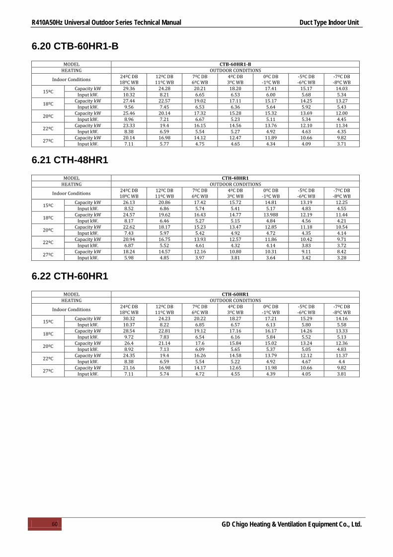
R410A50Hz Universal Outdoor Series Technical Manual Duct Type Indoor Unit
60 GD Chigo Heating & Ventilation Equipment Co., Ltd.
6.20 CTB-60HR1-B
MODEL CTB-60HR1-B HEATING OUTDOOR CONDITIONS
Indoor Conditions 24ºC DB 18ºC WB
12ºC DB 11ºC WB
7ºC DB 6ºC WB
4ºC DB 3ºC WB
0ºC DB -1ºC WB
-5ºC DB -6ºC WB
-7ºC DB -8ºC WB
15ºC Capacity kW 29.36 24.28 20.21 18.20 17.41 15.17 14.03 Input kW. 10.32 8.21 6.65 6.53 6.00 5.68 5.34
18ºC Capacity kW 27.44 22.57 19.02 17.11 15.17 14.25 13.27 Input kW. 9.56 7.45 6.53 6.36 5.64 5.92 5.43
20ºC Capacity kW 25.46 20.14 17.32 15.28 15.32 13.69 12.00 Input kW. 8.96 7.21 6.67 5.23 5.11 5.34 4.45
22ºC Capacity kW 23.33 19.4 16.15 14.56 13.76 12.10 11.34 Input kW. 8.38 6.59 5.54 5.27 4.92 4.63 4.35
27ºC Capacity kW 20.14 16.98 14.12 12.47 11.89 10.66 9.82 Input kW. 7.11 5.77 4.75 4.65 4.34 4.09 3.71
6.21 CTH-48HR1
MODEL CTH-48HR1 HEATING OUTDOOR CONDITIONS
Indoor Conditions 24ºC DB 18ºC WB
12ºC DB 11ºC WB
7ºC DB 6ºC WB
4ºC DB 3ºC WB
0ºC DB -1ºC WB
-5ºC DB -6ºC WB
-7ºC DB -8ºC WB
15ºC Capacity kW 26.13 20.86 17.42 15.72 14.81 13.19 12.25 Input kW. 8.52 6.86 5.74 5.41 5.17 4.83 4.55
18ºC Capacity kW 24.57 19.62 16.43 14.77 13.988 12.19 11.44 Input kW. 8.17 6.46 5.27 5.15 4.84 4.56 4.21
20ºC Capacity kW 22.62 18.17 15.23 13.47 12.85 11.18 10.54 Input kW. 7.43 5.97 5.42 4.92 4.72 4.35 4.14
22ºC Capacity kW 20.94 16.75 13.93 12.57 11.86 10.42 9.71 Input kW. 6.87 5.52 4.61 4.32 4.14 3.83 3.72
27ºC Capacity kW 18.24 14.57 12.16 10.80 10.31 9.11 8.42 Input kW. 5.98 4.85 3.97 3.81 3.64 3.42 3.28
6.22 CTH-60HR1
MODEL CTH-60HR1 HEATING OUTDOOR CONDITIONS
Indoor Conditions 24ºC DB 18ºC WB
12ºC DB 11ºC WB
7ºC DB 6ºC WB
4ºC DB 3ºC WB
0ºC DB -1ºC WB
-5ºC DB -6ºC WB
-7ºC DB -8ºC WB
15ºC Capacity kW 30.32 24.23 20.22 18.27 17.21 15.29 14.16 Input kW. 10.37 8.22 6.85 6.57 6.13 5.80 5.58
18ºC Capacity kW 28.54 22.81 19.12 17.16 16.17 14.26 13.33 Input kW. 9.72 7.83 6.54 6.16 5.84 5.52 5.13
20ºC Capacity kW 26.4 21.14 17.6 15.84 15.02 13.24 12.36 Input kW. 8.92 7.13 6.09 5.65 5.37 5.05 4.83
22ºC Capacity kW 24.35 19.4 16.26 14.58 13.79 12.12 11.37 Input kW. 8.38 6.59 5.54 5.22 4.92 4.67 4.4
27ºC Capacity kW 21.16 16.98 14.17 12.65 11.98 10.66 9.82 Input kW. 7.11 5.74 4.72 4.55 4.39 4.05 3.81

R410A50Hz Universal Outdoor Series Technical Manual Duct Type Indoor Unit
61 GD Chigo Heating & Ventilation Equipment Co., Ltd.
7.Static Pressure
7.1 CTA-18HR1
500400300200
10
20
30
40
50Pa
600 700 800 900 1000 1100Air volume(m /h)3
Ext
ern
al s
tatic
pre
ssu
re (
Pa
)
1200
CTA-18HR1
Super high speed
High speed
Mid speed
Low speed
7.2 CTA-24HR1
14001300
10
20
30
40
60Pa
800 900 1000 1100Air volume(m /h)3
Exte
rnal
sta
tic p
ress
ure
(Pa)
CTA-24HR1
1200 1500700
50
Super high speed
High speed
Mid speedLow speed

R410A50Hz Universal Outdoor Series Technical Manual Duct Type Indoor Unit
62 GD Chigo Heating & Ventilation Equipment Co., Ltd.
7.3 CTB-18HR1
14001300
10
20
30
40
60Pa
800 900 1000 1100Air volume(m /h)3
CTB-18HR1
1200 1500700
50 Super high speed
High speed
Mid speedLow speed
7.4 CTB-24HR1
14001300
10
20
30
40
60Pa
800 900 1000 1100Air volume(m /h)3
Exte
rnal
sta
tic p
ress
ure
(Pa)
CTB-24HR1
1200 1500700
50Super high speed
High speed
Mid speed
Low speed
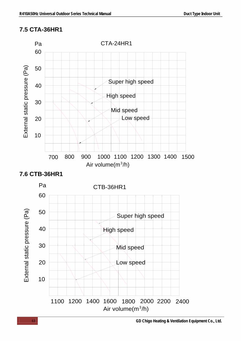
R410A50Hz Universal Outdoor Series Technical Manual Duct Type Indoor Unit
63 GD Chigo Heating & Ventilation Equipment Co., Ltd.
7.5 CTA-36HR1
14001300
10
20
30
40
60Pa
800 900 1000 1100Air volume(m /h)3
Ext
erna
l sta
tic p
ress
ure
(Pa)
CTA-24HR1
1200 1500700
50
Super high speed
High speed
Mid speedLow speed
7.6 CTB-36HR1
2400220016001400
10
20
30
40
50
60
1100Air volume(m /h)3
Exte
rnal
sta
tic p
ress
ure
(Pa)
CTB-36HR1
1200 1800 2000
Pa
Super high speed
High speed
Mid speed
Low speed

R410A50Hz Universal Outdoor Series Technical Manual Duct Type Indoor Unit
64 GD Chigo Heating & Ventilation Equipment Co., Ltd.
7.7 CTB-48HR1
2400220016001400
10
20
30
40
50
60
1100Air volume(m /h)3
Ext
erna
l sta
tic p
ress
ure
(Pa)
CTB-48HR1
1200 1800 2000
Pa
Super high speed
High speed
Mid speed
Low speed
7.8 CTB-60HR1
2400220016001400
10
20
30
40
50
60
1100Air volume(m /h)3
Ext
erna
l sta
tic p
ress
ure
(Pa)
CTB-60HR1
1200 1800 2000
Pa
Super high speed
High speed
Mid speed
Low speed

R410A50Hz Universal Outdoor Series Technical Manual Duct Type Indoor Unit
65 GD Chigo Heating & Ventilation Equipment Co., Ltd.
7.9 CTB-48HR1-B
2400220016001400
10
20
30
40
50
60
1100Air volume(m /h)3
Exter
nal s
tatic
press
ure (P
a)
CTB-48HR1-B
1200 1800 2000
Pa
70
80
90
100
110
120
130
140
2600 2800
160
High speed
Mid speed
Low speed
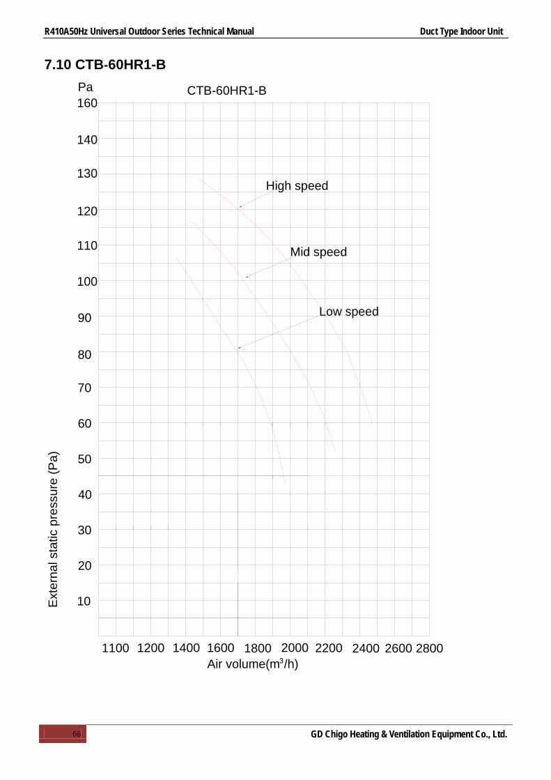
R410A50Hz Universal Outdoor Series Technical Manual Duct Type Indoor Unit
66 GD Chigo Heating & Ventilation Equipment Co., Ltd.
7.10 CTB-60HR1-B
2400220016001400
10
20
30
40
50
60
1100Air volume(m /h)3
Ext
erna
l sta
tic p
ress
ure
(Pa)
CTB-60HR1-B
1200 1800 2000
Pa
70
80
90
100
110
120
130
140
2600 2800
160
High speed
Mid speed
Low speed
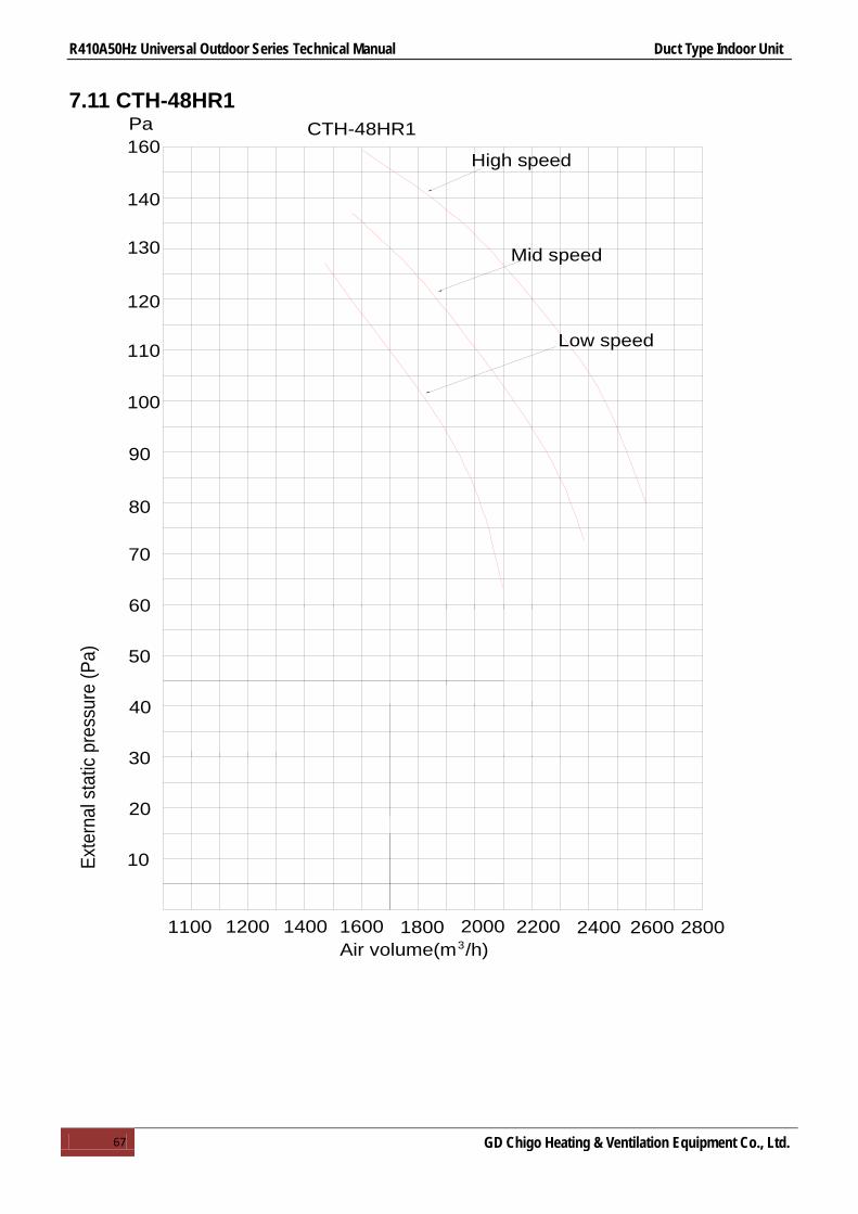
R410A50Hz Universal Outdoor Series Technical Manual Duct Type Indoor Unit
67 GD Chigo Heating & Ventilation Equipment Co., Ltd.
7.11 CTH-48HR1
2400220016001400
10
20
30
40
50
60
1100Air volume(m /h)3
Exte
rnal
sta
tic p
ress
ure
(Pa)
CTH-48HR1
1200 1800 2000
Pa
70
80
90
100
110
120
130
140
2600 2800
160High speed
Mid speed
Low speed

R410A50Hz Universal Outdoor Series Technical Manual Duct Type Indoor Unit
68 GD Chigo Heating & Ventilation Equipment Co., Ltd.
7.12 CTH-60HR1
2400220016001400
10
20
30
40
50
60
1100Air volume(m /h)3
Exte
rnal
static
pre
ssur
e (P
a)
CTH-60HR1
1200 1800 2000
Pa
70
80
90
100
110
120
130
140
2600 2800
160High speed
Mid speed
Low speed

R410A50Hz Universal Outdoor Series Technical Manual Duct Type Indoor Unit
69 GD Chigo Heating & Ventilation Equipment Co., Ltd.
8.Electric Characteristics
Model Indoor Units
Hz Voltage Min. Max. CTA-18HR1 50 220-240V 198 254 CTA-24HR1 50 220-240V 198 254 CTB-18HR1 50 220-240V 198 254 CTB-24HR1 50 220-240V 198 254 CTB-36HR1 50 220-240V 198 254 CTB-48HR1 50 220-240V 198 254 CTB-60HR1 50 220-240V 198 254
CTB-48HR1-B 50 220-240V 198 254 CTB-60HR1-B 50 220-240V 198 254
CTH-48HR1 50 220-240V 198 254 CTH-60HR1 50 220-240V 198 254
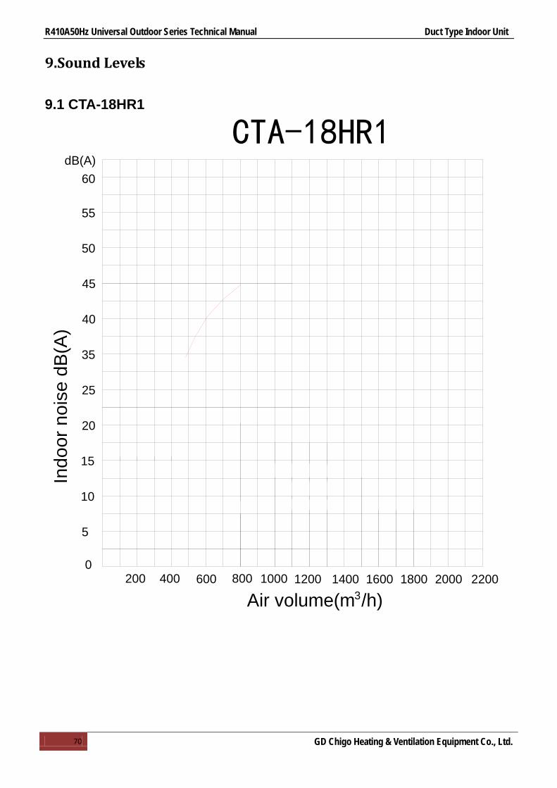
R410A50Hz Universal Outdoor Series Technical Manual Duct Type Indoor Unit
70 GD Chigo Heating & Ventilation Equipment Co., Ltd.
9.Sound Levels
9.1 CTA-18HR1
01400800600
Indo
or n
oise
dB
(A)
3Air volume(m /h)
dB(A)
50
45
40
35
25
20
15
10
5
200 400 1000 1200
CTA-18HR1
55
60
1600 1800 2000 2200
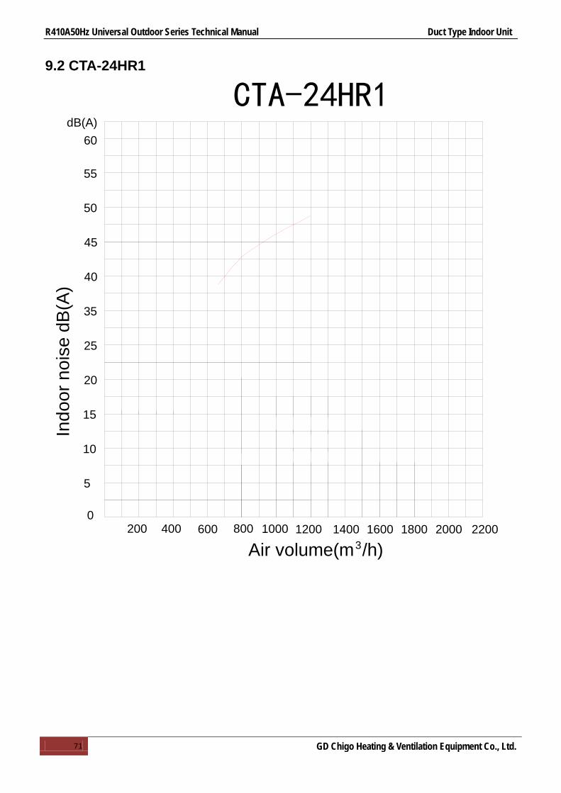
R410A50Hz Universal Outdoor Series Technical Manual Duct Type Indoor Unit
71 GD Chigo Heating & Ventilation Equipment Co., Ltd.
9.2 CTA-24HR1
01400800600
Indo
or n
oise
dB
(A)
3Air volume(m /h)
dB(A)
50
45
40
35
25
20
15
10
5
200 400 1000 1200
CTA-24HR1
55
60
1600 1800 2000 2200

R410A50Hz Universal Outdoor Series Technical Manual Duct Type Indoor Unit
72 GD Chigo Heating & Ventilation Equipment Co., Ltd.
9.3 CTB-18HR1
01400800600
Indo
or n
oise
dB
(A)
3Air volume(m /h)
dB(A)
50
45
40
35
25
20
15
10
5
200 400 1000 1200
CTB-18HR1
55
60
1600 1800 2000 2200

R410A50Hz Universal Outdoor Series Technical Manual Duct Type Indoor Unit
73 GD Chigo Heating & Ventilation Equipment Co., Ltd.
9.4 CTB-24HR1
01400800600
Indo
or n
oise
dB
(A)
3Air volume(m /h)
dB(A)
50
45
40
35
25
20
15
10
5
200 400 1000 1200
CTB-24HR1
55
60
1600 1800 2000 2200

R410A50Hz Universal Outdoor Series Technical Manual Duct Type Indoor Unit
74 GD Chigo Heating & Ventilation Equipment Co., Ltd.
9.5 CTB-36HR1
01400800600
Indo
or n
oise
dB(
A)
3Air volume(m /h)
dB(A)
50
45
40
35
25
20
15
10
5
200 400 1000 1200
CTB-36HR1
55
60
1600 1800 2000 2200

R410A50Hz Universal Outdoor Series Technical Manual Duct Type Indoor Unit
75 GD Chigo Heating & Ventilation Equipment Co., Ltd.
9.6 CTB-48HR1
CTB-48HR1
01400800600
Indo
or n
oise
dB
(A)
3Air volume(m /h)
dB(A)
50
45
40
35
25
20
15
10
5
200 400 1000 1200
55
60
1600 1800 2000 2200

R410A50Hz Universal Outdoor Series Technical Manual Duct Type Indoor Unit
76 GD Chigo Heating & Ventilation Equipment Co., Ltd.
9.7 CTB-60HR1
01400800600
Indo
or n
oise
dB
(A)
3Air volume(m /h)
dB(A)
50
45
40
35
25
20
15
10
5
200 400 1000 1200
CTB-60HR1
55
60
1600 1800 2000 2200

R410A50Hz Universal Outdoor Series Technical Manual Duct Type Indoor Unit
77 GD Chigo Heating & Ventilation Equipment Co., Ltd.
9.8 CTB-48HR1-B
01400800600
Indo
or n
oise
dB
(A)
3Air volume(m /h)
dB(A)
50
45
40
35
25
20
15
10
5
200 400 1000 1200
CTB-48HR1-B
55
60
1600 1800 2000 2200
65
2400 2600

R410A50Hz Universal Outdoor Series Technical Manual Duct Type Indoor Unit
78 GD Chigo Heating & Ventilation Equipment Co., Ltd.
9.9 CTB-60HR1-B
01400800600
Indo
or n
oise
dB
(A)
3Air volume(m /h)
dB(A)
50
45
40
35
25
20
15
10
5
200 400 1000 1200
CTB-60HR1-B
55
60
1600 1800 2000 2200
65
2400 2600

R410A50Hz Universal Outdoor Series Technical Manual Duct Type Indoor Unit
79 GD Chigo Heating & Ventilation Equipment Co., Ltd.
9.10 CTH-48HR1
01400800600
Indo
or n
oise
dB(
A)
3Air volume(m /h)
dB(A)
50
45
40
35
25
20
15
10
5
200 400 1000 1200
CTH-48HR1
55
60
1600 1800 2000 2200
65
2400 2600

R410A50Hz Universal Outdoor Series Technical Manual Duct Type Indoor Unit
80 GD Chigo Heating & Ventilation Equipment Co., Ltd.
9.11 CTH-60HR1
01400800600
Indo
or n
oise
dB(
A)
3Air volume(m /h)
dB(A)
50
45
40
35
25
20
15
10
5
200 400 1000 1200
CTH-60HR1
55
60
1600 1800 2000 2200
65
2400 2600

R410A50Hz Universal Outdoor Series Technical Manual Duct Type Indoor Unit
81 GD Chigo Heating & Ventilation Equipment Co., Ltd.
10.Accessories
Name Shape Quantity
Tubing & Fittings
Soundproof/insulation sheath
2
Binding tape
1
Seal sponge
1
Drainpipe Fittings Seal ring
1
Controller
Wire controller
1
Remote controller (optional)
1
others Operation & installation instruction manual
1

R410A50Hz Universal Outdoor Series Technical Manual Duct Type Indoor Unit
82 GD Chigo Heating & Ventilation Equipment Co., Ltd.
11.The Specification of Wiring
Type CTA-18HR1 CTA-24HR1 CTB-18HR1 CTB-24HR1 CTB-36HR1 CTB-48HR1
Power Phase 1-phase 1-phase 1-phase 1-phase 1-phase 1-phase
Frequency and Voltage 220-240V, 50Hz
Indoor Unit Power Wiring (mm2) 3×2.5mm2 3×1.0mm2 3×2.5mm2 3×1.0mm2 3×1.0mm2 3×1.0mm2
Indoor/Outdoor Connecting
Wiring (mm2)
Ground Wiring 1.0mm2 1.0mm2 1.0mm2 1.0mm2 1.0mm2 1.0mm2
Strong Electric Signal
5×0.75mm2 5×0.75mm2 5×0.75mm2
5×0.75mm2
5×0.75mm2
5×0.75mm2
Type CTB-60HR1 CTB-48HR1-B CTB-60HR1-B CTH-48HR1 CTH-60HR1
Power Phase 1-phase 1-phase 1-phase 1-phase 1-phase
Frequency and Voltage 220-240V, 50Hz
Indoor Unit Power Wiring (mm2) 3×1.0mm2 3×1.0mm2 3×1.0mm2 3×1.0mm2 3×1.0mm2
Indoor/Outdoor Connecting
Wiring (mm2)
Ground Wiring 1.0mm2 1.0mm2 1.0mm2 1.0mm2 1.0mm2
Strong Electric Signal
5×0.75mm2 5×0.75mm2 5×0.75mm2 5×0.75mm2 5×0.75mm2

R410A50Hz Universal Outdoor Series Technical Manual Duct Type Indoor Unit
83 GD Chigo Heating & Ventilation Equipment Co., Ltd.
12.Field Wiring
CTA-18HR1&COU-18HR1,CTB-18HR1&COU-18HR1 CTA-24HR1&COU-24HR1
CTB-24HR1&COU-24HR1 CTB-36HR1&COU-36HR1
CTB-36HR1&COU-36HSR1 CTB-48HR1&COU-48HSR1 CTB-60HR1&COU-60HSR1 CTB-48HR1-B&COU-48HS1 CTB-60HR1-B&COU-60HSR1 CTH-48HR1&COU-48HSR1 CTH- 60HR1&COU-60HSR1

R410A50Hz Universal Outdoor Series Technical Manual Duct Type Indoor Unit
84 GD Chigo Heating & Ventilation Equipment Co., Ltd.
13.Exploded View
13.1 CTA-18HR1
No. Part Name Quantity No. Part Name Quantity
1 Welding assy for water collector 1 16 Centrifugal fan 3
2 Fixing board for inlet and outlet pipe 1 17 Fan motor 1
3 Pipe clamp 2 1 18 Upper scroll case 3
4 Pipe clamp 1 1 19 Coupling 1
5 Front-left clapboard 1 20 Axis2 1
6 Evaporator 1 21 Louver fixing board assy 1
7 Left end plate of Evaporator 1 22 No.13 Bearing holder 1
8 Rear-left clapboard 1 23 Motor support 1
9 Installing board for E-parts 1 24 Fan fixing board assy 1
10 Main control board 1 25 Front hanger B 1
11 PTC transformer 1 26 hanger 2
12 E-parts box cover assy 1 27 Right clapboard 1
13 Terminal 1 28 Right end plate of Evaporator 1
14 Upper cover 1 29 Evaporator chassis 1
15 Lower scroll case 3 30 Front hanger A 1

R410A50Hz Universal Outdoor Series Technical Manual Duct Type Indoor Unit
85 GD Chigo Heating & Ventilation Equipment Co., Ltd.
13.2 CTA-24HR1
No. Part Name Quantity No. Part Name Qua
ntity
1 Welding assy for water collector 1 20 Fan motor 1 2 Fixing board for inlet and outlet pipe 1 21 Centrifugal fan 4 3 Pipe clamp 2 1 22 Coupling 2 4 Pipe clamp 1 1 23 Louver fixing board assy 2 7 Evaporator chassis 1 24 No.13 Bearing holder 2 8 Installing board for E-parts 1 25 Motor support 2 9 Main control board 1 26 Upper cover 1 10 PTC transformer 1 27 Front hanger B 1 11 Terminal 1 28 Hanger 2 12 E-parts box cover assy 1 29 Right clapboard 1 13 Front-left clapboard 1 30 Pre-welding assy for evaporator 1 14 Rear-left clapboard 1 30.1 Evaporator 1
15 Front hanger A 1 30.2 Distributing capillary assy for indoor unit 1
16 Fan fixing board assy 1 30.3 Collecting pipe assy 1 17 Lower scroll case 4 30.4 Installation tube for probe 1 18 Axis2 2 30.5 Installation spring for probe 1 19 Upper scroll case 4

R410A50Hz Universal Outdoor Series Technical Manual Duct Type Indoor Unit
86 GD Chigo Heating & Ventilation Equipment Co., Ltd.
13.3 CTB-18HR1, CTB-24HR1
No. Part Name Quantity No. Part Name Quantity
1 outlet assy 1 11 scroll case(left) 1
2 hanger 4 12 Fan motor 1
3 left clapboard 1 13 scroll case(right) 1
4 Left end plate of Evaporator 1 14 Fan fixing board assy 1
5 Evaporator assy 1 15 E-parts box cover assy 1
5.1 Transition tube 6 16 Small cover plate 1
5.2 Shunt assy 1 17 E-parts 1
5.3 air header assy 1 17.1 Main control board 1
5.4 Evaporator 1 17.2 Temperature sensor 1
5.5 Probe copper tube 1 17.3 PTC transformer 1
6 Welding assy for water collector 1 17.4 Terminal 1
6.1 leading 2 17.5 NO.7Line pressing buckle 2
6.2 effluent joint rubber cap 2 18 E-parts box base 1
7 Lower plate 1 19 big cover plate 1
8 Return air damper 1 20 Right clapboard 1
9 filter screen 2 21 Right end plate of Evaporator 1
10 Return air assy 1 22 Upper plate 1
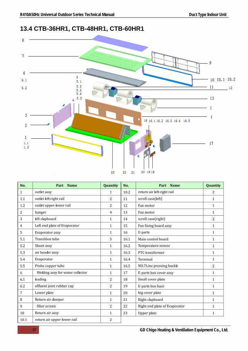
R410A50Hz Universal Outdoor Series Technical Manual Duct Type Indoor Unit
87 GD Chigo Heating & Ventilation Equipment Co., Ltd.
13.4 CTB-36HR1, CTB-48HR1, CTB-60HR1
No. Part Name Quantity No. Part Name Quantity
1 outlet assy 1 10.2 return air left-right rail 2
1.1 outlet left-right rail 2 11 scroll case(left) 1
1.2 outlet upper-lower rail 2 12 Fan motor 1
2 hanger 4 13 Fan motor 1
3 left clapboard 1 14 scroll case(right) 2
4 Left end plate of Evaporator 1 15 Fan fixing board assy 1
5 Evaporator assy 1 16 E-parts 1
5.1 Transition tube 5 16.1 Main control board 1
5.2 Shunt assy 1 16.2 Temperature sensor 1
5.3 air header assy 1 16.3 PTC transformer 1
5.4 Evaporator 1 16.4 Terminal 1
5.5 Probe copper tube 1 16.5 NO.7Line pressing buckle 2
6 Welding assy for water collector 1 17 E-parts box cover assy 1
6.1 leading 2 18 Small cover plate 1
6.2 effluent joint rubber cap 2 19 E-parts box base 1
7 Lower plate 1 20 big cover plate 1
8 Return air damper 1 21 Right clapboard 1
9 filter screen 2 22 Right end plate of Evaporator 1
10 Return air assy 1 23 Upper plate 1
10.1 return air upper-lower rail 2

R410A50Hz Universal Outdoor Series Technical Manual Duct Type Indoor Unit
88 GD Chigo Heating & Ventilation Equipment Co., Ltd.
13.5 CTB-48HR1-B, CTH-48HR1
No. Part Name Quantity No. Part Name Quantity
1 capacitance clamping 1 9.3 Terminal 1 2 compressor capacitor 1 10 chassis parts 1 3 Filter 2 11 foam water collector 1 4 back panel 1 12 front panel assembly 1 5 Evaporator assemble 1 13 left clapboard 1 6 Right clapboard 1 14 Fan fixing board assy 1 7 hanger 4 15 fan assy 1 8 E-parts box cover assy 1 15.1 fan motor 1 9 E-parts 1 15.2 scroll case(left) 1 9.1 Main control board 1 15.3 scroll case(right) 1 9.2 Transformer 1 16 up panel assembly 1

R410A50Hz Universal Outdoor Series Technical Manual Duct Type Indoor Unit
89 GD Chigo Heating & Ventilation Equipment Co., Ltd.
13.6 CTB-60HR1-B, CTH-60HR1
No. Part Name Quantity No. Part Name Quantity
1 capacitance clamping 1 9.3 Terminal 1 2 compressor capacitor 1 10 chassis parts 1 3 filter 2 11 foam water collector 1 4 back panel 1 12 front panel assembly 1 5 Evaporator assemble 1 13 left clapboard 1 6 Right clapboard 1 14 Fan fixing board assy 1 7 hanger 4 15 fan assy 1 8 E-parts box cover assy 1 15.1 fan motor 1 9 E-parts 1 15.2 scroll case(left) 1 9.1 Main control board 1 15.3 scroll case(right) 1 9.2 transformer 1 16 up panel assembly 1

R410A50Hz Universal Outdoor Series Technical Manual Duct Type Indoor Unit
90 GD Chigo Heating & Ventilation Equipment Co., Ltd.
14.Troubleshooting
Table 1 Symptoms Causes Solution
Unit does not start
Power failure
Power switch is off
Fuse of power switch may have burned
Batteries of remote controller exhausted or other
problem of controller
Wait for the comeback of power
Switch on the power
Repilocation
Replace the batterises or check the
controller
Air flowing normally but
conpletely can’t cooling
Temperature is not set correctlly
Be in 3 minutes protection of compressor
Set the temperature properly
Wait
Units start or stop
frequently
Refrigerant i s too little or too much
Air or no concreting gas in the refrigerating circuit
Compressor i s malfunction
Voltage is too high or too low
System circuit is bolcked
Check leakage ,and rightly recharge
refrigerant
Vacuum and recharge refrigerant
Mainternance or change compressor
Install manostat
Find reasons and solution
Low cooling effect
Outdoor unit and indoor unit heat exchanger is dirty
The air filter is dirty
Inlet/Outlet of indoor/outdoor units is blocked
Doors and windows are open
Sunlight directly shine
Too much heat resource
Outdoor temp. Is too high
Leakage of refrigerant or lack of refrigerant
Clean the heat exchanger
Clean the air filter
Eliminate all dirties and make air smooth
Close doors and windows
Make curtains in order to shelter form
sunshine
Reduce heat source
AC cooling capacity reduces(normal)
Check leakage and rightly recharge
refrigerant
Low heating effect
Outdoor temperature is lower than 7℃
Door and windows not completelty closed
Leakage of refrigerant or lack of refrigerant
Use heating decvice
Close doors and windows
Check leakage and rightly recharge
refrigerant

R410A50Hz Universal Outdoor Series Technical Manual Duct Type Indoor Unit
91 GD Chigo Heating & Ventilation Equipment Co., Ltd.
Table 2 Symptoms Solution Causes
The fan speed can not be changed
Check whether the MODE indicated on the display is “AUTO”
When the automatic mode is selected, the air conditioner will automatically change the fan speed
Check whether the MODE indicated on the display is “DEHUINIDIFICATION”
When dry operation is selected. the air conditioner automatically change the fan speed.The fan speed can be selected during “COOL”,”FAN NOLY”,and “HEAT”
The wire controller signal is not tea transmitted even when the ON/OFF button is pushed
Check whether the signal transmitter of the wire controller is properly directed to the infrared signal receiver of the indoor unit
The power supply is off
The TEMP. indicator does not come on.
Check whether the MODE indicated on the display is FAN ONLY
The temperature cannot be set during FAN mode
The indication on the display disappears after a lapse of time
Check whether the timer operation has come to an end when the TIMER OFF is indicated on the display
The air conditioner operation will stop up to the set time
The TIMER ON indicator goes off after a lapse of certain time
Check whether the timer operation is started when the TIMER ON is indicated on the display
Up to the set time,the air conditioner will automatically start and appropriate indicator will go off
NO receiving tone sounds from the indoor unit even when the ON/OFF button is pressed
Check whether the signal transmitter of the wire controller is properly directed to the infrared signal receiver of the indoor unit when the ON/OFF button is pressed
Directly transmit the signal transmitter of the wire controller to the infrared signal receiver of the indoor unit, and then repeatly push the ON/OFF button twice
Fault code table
No. Type Content Code Remark
1 Fault Room temperature sensor fault E2
Automatic recovery after the problem resolved
2 Fault Indoor coil temperature sensor fault E3
3 Fault Outdoor coil temperature sensor fault E5
4 Fault Water full protection F5
5 Fault Outdoor protection F2
6 Fault Communication fault E1 Manual eliminate
7 Fault EEPROM communication fault P6 Recovery after interruption of power supply
8 Indication Enforced cooling /
9 Indication Anti- cool air in heating mode P1
10 Indication Defrosting P3
R410A50Hz Universal Outdoor Series Technical Manual Floor & Ceiling Indoor Unit
92 GD Chigo Heating & Ventilation Equipment Co., Ltd.
Floor & Ceiling
1.Features .................................................................................. 93
2.Specifications .......................................................................... 94
3.Dimensions ............................................................................. 96
4.Service Space .......................................................................... 98
5.Wiring Diagrams ...................................................................... 99
6.Capacity Table ....................................................................... 101
7.Electric Characteristics .......................................................... 105
8.Sound Levels ......................................................................... 106
9.Exploded View ...................................................................... 109
10.Accessories .......................................................................... 113
11.The Specification of Power .................................................. 114
12.Field Wiring ........................................................................ 115
13.Troubleshooting .................................................................. 116

R410A50Hz Universal Outdoor Series Technical Manual Floor & Ceiling Indoor Unit
93 GD Chigo Heating & Ventilation Equipment Co., Ltd.
1.Features
1.1 Flexible installation, ceiling suspended and floor standing. 1.2 Adopting centrifugal fans, higher ESP and longer air flow distance. 1.3 Auto-swing function, built-in two louver motor, vertical and horizontal air-flow adjustment. 1.4 Washable air filter 1.5 Adopting waterproof plastic film on water collector, avoiding water leakage. 1.6 Self-diagnostic function and multi protection. 1.7 Auto-restart function. 1.8 Standard for wireless controller; option for wired controller

R410A50Hz Universal Outdoor Series Technical Manual Floor & Ceiling Indoor Unit
94 GD Chigo Heating & Ventilation Equipment Co., Ltd.
2.Specifications Model CUA-18HR1 CUA-24HR1 CUA-36HR1
Indoor power supply V/Ph/Hz 220~240/1/50 220~240/1/50 220~240/1/50
Cooling
Capacity Btu/h 18000 24000 36000
KW 5.3 7.1 10.5
Input W 65 150 300
Rated current A 0.3 0.68 1.36
EER W/W 2.7 2.78 2.62
Heating
Capacity Btu/h 19800 26400 39600
KW 5.8 7.8 11.5
Input W 65 150 300
Rated current A 0.3 0.68 1.36
COP W/W 3.3 3.47 3.19
Indoor fan
motor
Model YSK110-65LD-4P3H85 YSK110-75LD-4P2 YSK110-180LD-4P2
Input W 65 150 300
Capacitor μF 3 5 5
Speed(Hi/Med/Lo) r/min 1350/1270/1180 980/880/780 1330/1080/910
Indoor coil
Number of rows 3 2 3
Tube pitch x row pitch mm 25×21.65 25×21.65 25×21.65
Fin spacing mm 2 1.4 1.7
Fin type Hydrophilic Hydrophilic Hydrophilic
Tube outside dia. and
type mm
Ф9.52 Ф9.52 Ф9.52
inner grooved inner grooved inner grooved
Coil size(W x H x D) mm 610x250x64.95 982×250×43.3 982×250×64.95
Number of circuits 3 5 5
Indoor air flow(Hi/Med/Lo) m3/h 790/670/540 1100/860/740 1700/1300/1100
Indoor noise level(Hi/Med/Lo) dB(A) 51/47/43 47/45/43 50/46/43
Indoor unit
Dimension(W×H×D) mm 880×635×203 1245×680×247 1245×680×247
Packing(W×H×D) mm 970×711×301 1325×770×325 1325×770×325
Net/Gross weight kg 30/32 35/41 37/43
Refrigerant type R410A R410A R410A
Refrigerant piping Liquid side/Gas
side mm Φ6.35/Φ12.7 Φ9.52/Φ15.88 Φ9.52/Φ19.05
Drainage pipe mm 30 30 30
Connection
wiring
Power Supply From indoor unit From outdoor unit From outdoor unit
Indoor power wiring mm2 2.5 1.0 1.0
Signal wiring mm2 1.5 0.75 0.75
Controller Standard for remote controller(wired controller for option)
Operation temp °C 16~32 16~32 16~32
Ambient temp °C -7~43 -7~43 -7~43 Application area m2 20-35 28-50 40-70 Stuffing Quantity(20'/40'/40'HQ) 132/270/306 75/165/189 75/165/189 Notes: 1. Nominal cooling capacities are based on the following conditions:
Indoor temp: 27°CDB, 19°CWB; Outdoor temp: 35°CDB; Equivalent ref. Piping: 7.5m(horizontal) 2. Nominal heating capacities are based on the following conditions:
Indoor temp: 20°CDB; Outdoor temp: 7°CDB, 6°CWB; Equivalent ref. Piping: 7.5m(horizontal) 3. Actual noise level may differ, depending on the room structure, etc, since these noise values are from an anechoic room.

R410A50Hz Universal Outdoor Series Technical Manual Floor & Ceiling Indoor Unit
95 GD Chigo Heating & Ventilation Equipment Co., Ltd.
Notes: 1. Nominal cooling capacities are based on the following conditions: Indoor temp: 27°CDB, 19°CWB; Outdoor temp: 35°CDB; Equivalent ref. Piping: 7.5m(horizontal)
2. Nominal heating capacities are based on the following conditions: Indoor temp: 20°CDB; Outdoor temp: 7°CDB, 6°CWB; Equivalent ref. Piping: 7.5m(horizontal)
3.Actual noise level may differ, depending on the room structure, etc, since these noise values are from an anechoic room.
Model CUA-48HR1 CUA-60HR1 Indoor power supply V/Ph/Hz 220~240/1/50 220~240/1/50
Cooling
Capacity Btu/h 48000 60000
KW 14 16
Input W 330 330
Rated current A 1.5 1.5
EER W/W 2.63 2.65
Heating
Capacity Btu/h 52800 66000
KW 15.4 16.6
Input W 330 330
Rated current A 1.5 1.5
COP W/W 2.84 2.71
Indoor fan motor
Model YSK110-59LD-4P17 YSK110-59LD-4P17
Input W 165+165 165+165
Capacitor μF 3+3 3+3
Speed(Hi/Med/Lo) r/min 1310/1139/1016 1310/1139/1016
Indoor coil
Number of rows 2 2
Tube pitch x row pitch mm 25×21.65 25×21.65
Fin spacing mm 1.5 1.5
Fin type Hydrophilic Hydrophilic
Tube outside dia. and
type mm
Ф9.52 Ф9.52
inner grooved inner grooved
Coil size(W×H×D) mm 1360×250×43.3 1360×250×43.3
Number of circuits 5 5
Indoor air flow(Hi/Med/Lo) m3/h 2300/1900/1500 2300/1900/1600
Indoor noise level(Hi/Med/Lo) dB(A) 55/52/50 55/52/50
Indoor unit
Dimension(W×H×D) mm 1670×680×247 1670×680×247
Packing(W×H×D) mm 1750×770×325 1750×770×325
Net/Gross weight kg 47/54 47/54
Refrigerant type R410A R410A
Refrigerant
piping Liquid side/Gas side mm Φ9.52/Φ19.05 Φ9.52/Φ19.05
Drainage pipe mm 30 30
Connection
wiring
Power Supply From outdoor unit From outdoor unit
Indoor power wiring mm2 1.0 1.0
Signal wiring mm2 0.75 0.75
Controller Standard for remote controller(wired controller for option)
Operation temp °C 16~32 16~32
Ambient temp °C -7~43 -7~43
Application area m2 55~95 60~105
Stuffing Quantity(20'/40'/40'HQ) 60/120/123 60/120/123

R410A50Hz Universal Outdoor Series Technical Manual Floor & Ceiling Indoor Unit
96 GD Chigo Heating & Ventilation Equipment Co., Ltd.
3.Dimensions
3.1 CUA-18HR1
727.21
136.
628
0
879.95
635.
39
203
208
3.2 CUA-24HR1, CUA-36HR1
1119
150
200
235
124568
0
247

R410A50Hz Universal Outdoor Series Technical Manual Floor & Ceiling Indoor Unit
97 GD Chigo Heating & Ventilation Equipment Co., Ltd.
3.3 CUA-48HR1, CUA-60HR1
1544
150
200
1670
680
235247

R410A50Hz Universal Outdoor Series Technical Manual Floor & Ceiling Indoor Unit
98 GD Chigo Heating & Ventilation Equipment Co., Ltd.
4.Service Space

R410A50Hz Universal Outdoor Series Technical Manual Floor & Ceiling Indoor Unit
99 GD Chigo Heating & Ventilation Equipment Co., Ltd.
5.Wiring Diagrams
5.1 CUA-18HR1
CN20
ROOM SENSOR
CN21
INDOOR PIPE SENSOR
CN1
10
ON
L
CNE
REMOTE
CONTROLLER
FMI
N
L N
BK BL
YE/
GN
3
TO POWER TO OUTDOOR
TR
CNT
CN4T
CN4T-2
CN120BK
BL
YE
RD
4
LCD SCREEN
ROO
M SE
NSOR
REM
OTE
CONT
ROLL
ER
5
1 2(N)
CN22
GYBK
COM
OR
TB
CO
ML
MH
OUTDOOR FAN
4-LOUVER MOTOR
OUT
DOOR
PIPE
SENSOR
YE/
GN
AJ1 AJ3AJ2
AJ4
52C
BK
BL
FM
YE/
GN
COR
OR

R410A50Hz Universal Outdoor Series Technical Manual Floor & Ceiling Indoor Unit
100 GD Chigo Heating & Ventilation Equipment Co., Ltd.
5.2 CUA24HR1,CUA-36HR1,CUA-48HR1,CUA-60HR1
CN20
RO
OM
SE
NS
OR
CN21
IND
OO
R P
IPE
SE
NS
OR
CN1
5
LOU
VE
R M
OTO
R
105
ON
L
CN
EC
NM
1
CN
M2C
NM
4
CN
M3
REM
OTE
CO
NTR
OLL
ER
FMI
N
L NBK BL
YE/
GN
3
TO POWER TO OUTDOOR
TR
CN
TC
N4T
CN
4T-2
AJ1 A
J3AJ2
CN120
AJ4
YE/
GN
FM1
C1
WH
WH
YE/
GN
FM2
C2
WH
WH
BKBL
YER
D
54B
R
BL
5
LCDS
CREE
N
ROOM SENSOR
REMOTE CONTROLLER
1 2G
Y
RD
CO
M1
OR
TB
CO
ML
MH
OUTDOOR FAN
4-LOUVER MOTOR
FEED BACK
OUTDOOR
PIPE
SENSOR
BK

R410A50Hz Universal Outdoor Series Technical Manual Floor & Ceiling Indoor Unit
101 GD Chigo Heating & Ventilation Equipment Co., Ltd.
6.Capacity Table
Cooling 6.1 CUA-18HR1
MODEL CUA-18HR1 COOLING OUTDOOR TEMPERATURE DRY
Indoor Conditions 21ºC 25ºC 30ºC 35ºC 40ºC 45ºC
21ºC D 15ºC W
Total capacity Kw 5.21 4.98 4.79 4.52 4.36 4.21 Sensitive capacity kW 4.16 3.96 3.84 3.61 3.47 3.35 Input kW. 1.18 1.36 1.53 1.69 1.86 2.03
24ºC D 17ºC W
Total capacity kW 5.7 5.47 5.26 4.95 4.78 4.61 Sensitive capacity kW 4.56 4.35 4.2 3.96 3.811 3.71 Input kW. 1.21 1.42 1.61 1.79 1.97 2.15
27ºC D 19ºC W
Total capacity kW 6.2 5.95 5.71 5.3 5.16 5.01 Sensitive capacity kW 4.95 4.74 4.55 4.31 4.13 4.03 Input kW. 1.31 1.51 1.71 1.78 2.07 2.26
32ºC D 23ºC W
Total capacity kW 7.13 6.84 6.57 6.22 5.94 5.77 Sensitive capacity kW 5.69 5.45 5.25 4.95 4.75 4.62 Input kW. 1.51 1.72 1.96 2.17 2.38 2.61
6.2 CUA-24HR1
MODEL CUA-24HR1 COOLING OUTDOOR TEMPERATURE DRY
Indoor Conditions 21ºC 25ºC 30ºC 35ºC 40ºC 45ºC
21ºC DB 15ºC WB
Total capacity kW 6.85 6.55 6.31 5.94 5.71 5.54 Sensitive capacity kW 5.47 5.24 5.04 4.75 4.56 4.43 Input kW. 1.68 1.91 2.15 2.4 2.65 2.91
24ºC DB 17ºC WB
Total capacity kW 7.52 7.18 6.91 6.52 6.26 6.05 Sensitive capacity kW 6.01 5.74 5.53 5.21 4.98 4.84 Input kW. 1.78 2.01 2.27 2.52 2.78 3.06
27ºC DB 19ºC WB
Total capacity kW 8.15 7.79 7.51 7.10 6.81 6.58 Sensitive capacity kW 6.51 6.24 5.98 5.66 5.44 5.26 Input kW. 1.87 2.13 2.39 2.54 2.93 3.22
32ºC DB 23ºC WB
Total capacity kW 9.37 8.96 8.63 8.16 7.82 7.57 Sensitive capacity kW 7.49 7.17 6.91 6.51 6.25 6.05 Input kW. 2.15 2.42 2.75 3.05 3.39 3.69
6.3 CUA-36HR1
MODEL CUA-36HR1 COOLING OUTDOOR TEMPERATURE DRY
Indoor Conditions 21ºC 25ºC 30ºC 35ºC 40ºC 45ºC
21ºC DB 15ºC WB
Total capacity kW 10.12 9.68 9.33 8.81 8.45 8.18 Sensitive capacity kW 8.09 7.75 7.46 7.03 6.75 6.55 Input kW. 2.34 2.68 3.02 3.41 3.73 4.07
24ºC DB 17ºC WB
Total capacity kW 11.1 10.61 10.23 9.64 9.26 8.96 Sensitive capacity kW 8.87 8.48 8.16 7.72 7.42 7.15 Input kW. 2.47 2.83 3.19 3.58 3.94 4.3
27ºC DB 19ºC WB
Total capacity kW 12.06 11.54 11.12 10.50 10.1 9.75 Sensitive capacity kW 9.65 9.24 8.89 8.38 8.04 7.79 Input kW. 2.64 3.03 3.37 3.79 4.15 4.48
32ºC DB 23ºC WB
Total capacity kW 13.86 13.26 12.78 12.06 11.58 11.21 Sensitive capacity kW 11.09 10.61 10.23 9.65 9.26 8.97 Input kW. 3.01 3.46 3.91 4.33 4.75 5.16

R410A50Hz Universal Outdoor Series Technical Manual Floor & Ceiling Indoor Unit
102 GD Chigo Heating & Ventilation Equipment Co., Ltd.
6.4 CUA-48HR1
MODEL CUA-48HSR1 COOLING OUTDOOR TEMPERATURE DRY
Indoor Conditions 21ºC 25ºC 30ºC 35ºC 40ºC 45ºC
21ºC DB 15ºC WB
Total capacity kW 13.51 12.92 12.45 11.74 11.27 10.92 Sensitive capacity kW 10.86 10.33 9.96 9.38 9.01 8.73 Input kW. 2.95 3.41 3.85 4.21 4.68 5.12
24ºC DB 17ºC WB
Total capacity kW 14.84 14.16 13.63 12.86 12.35 11.96 Sensitive capacity kW 11.83 11.32 10.91 10.28 9.87 9.54 Input kW. 3.15 3.59 4.01 4.49 4.94 5.41
27ºC DB 19ºC WB
Total capacity kW 16.06 15.38 14.82 14.00 13.42 12.98 Sensitive capacity kW 12.92 12.31 11.89 11.16 10.74 10.4 Input kW. 3.27 3.79 4.21 5.15 5.25 5.68
32ºC DB 23ºC WB
Total capacity kW 18.49 17.7 17.05 16.08 15.42 14.97 Sensitive capacity kW 14.79 14.15 13.63 12.86 12.33 11.98 Input kW. 3.82 4.35 4.88 5.45 5.98 6.52
6.5 CUA-60HR1
MODEL CCA-60HSR1 COOLING OUTDOOR TEMPERATURE DRY
Indoor Conditions 21ºC 25ºC 30ºC 35ºC 40ºC 45ºC
21ºC DB 15ºC WB
Total capacity kW 15.45 14.78 14.3 13.44 12.91 12.49 Sensitive capacity kW 12.38 11.83 11.39 10.75 10.32 10.02 Input kW. 3.76 4.32 4.84 5.38 5.92 6.46
24ºC DB 17ºC WB
Total capacity kW 16.93 16.19 15.6 14.72 14.13 13.7 Sensitive capacity kW 13.54 12.96 12.48 11.78 11.31 10.96 Input kW. 3.97 4.55 5.13 5.67 6.26 6.83
27ºC DB 19ºC WB
Total capacity kW 18.4 17.6 16.96 16 15.36 14.88 Sensitive capacity kW 14.72 14.1 13.57 12.81 12.3 11.92 Input kW. 4.20 4.78 5.39 5.96 6.58 7.19
32ºC DB 23ºC WB
Total capacity kW 21.16 20.24 19.51 18.39 17.67 17.12 Sensitive capacity kW 16.93 16.13 15.6 14.73 14.12 13.71 Input kW. 4.83 5.52 6.21 6.89 7.59 8.26

R410A50Hz Universal Outdoor Series Technical Manual Floor & Ceiling Indoor Unit
103 GD Chigo Heating & Ventilation Equipment Co., Ltd.
Heating 6.6 CUA-18HR1
MODEL CUA-18HR1 HEATING OUTDOOR CONDITIONS
Indoor Conditions
24ºC D 18ºC W
12ºC D 11ºC W
7ºC D 6ºC W
4ºC D 3ºC W
0ºC D -1ºC W
-5ºC D -6ºC W
-7ºC D -8ºC W
15ºC Capacity kW 10.28 8.21 6.88 6.2 5.85 5.16 4.81
Input kW. 3.16 2.52 2.12 1.99 1.9 1.79 1.68
18ºC Capacity kW 9.67 7.72 6.45 5.81 5.49 4.85 4.52
Input kW. 2.94 2.33 1.97 1.88 1.78 1.68 1.58
20ºC Capacity kW 8.87 7.12 5.8 5.38 5.08 4.49 4.18
Input kW. 2.71 2.15 1.71 1.75 1.66 1.55 1.46
22ºC Capacity kW 8.21 6.56 5.51 4.96 4.66 4.13 3.85
Input kW. 2.48 2.01 1.69 1.61 1.51 1.43 1.35
27ºC Capacity kW 7.15 5.72 4.78 4.3 4.06 3.58 3.37
Input kW. 2.15 1.75 1.46 1.38 1.32 1.24 1.15
6.7 CUA-24HR1
MODEL CUA-24HR1 HEATING OUTDOOR CONDITIONS
Indoor Conditions
24ºC D 18ºC W
12ºC D 11ºC W
7ºC D 6ºC W
4ºC D 3ºC W
0ºC D -1ºC W
-5ºC D -6ºC W
-7ºC D -8ºC W
15ºC Capacity kW 13.68 10.91 9.12 8.24 7.78 6.86 6.42
Input kW. 4.78 3.76 3.12 2.95 2.78 2.68 2.54
18ºC Capacity kW 12.85 10.27 8.56 7.68 7.31 6.42 6.01
Input kW. 4.48 3.43 2.84 2.76 2.61 2.46 2.36
20ºC Capacity kW 11.89 9.48 7.8 7.16 6.78 5.92 5.58
Input kW. 4.08 3.26 2.33 2.31 2.26 2.22 2.15
22ºC Capacity kW 10.95 8.76 7.31 6.58 6.24 5.5 5.12
Input kW. 3.78 2.96 2.25 2.28 2.21 2.08 1.98
27ºC Capacity kW 9.51 7.57 6.34 5.72 5.42 4.68 4.46
Input kW. 3.27 2.45 2.14 2.08 1.98 1.83 1.68 6.8 CUA-36HR1
MODEL CUA-36HR1 HEATING OUTDOOR CONDITIONS
Indoor Conditions
24ºC D 18ºC W
12ºC D 11ºC W
7ºC D 6ºC W
4ºC D 3ºC W
0ºC D -1ºC W
-5ºC D -6ºC W
-7ºC D -8ºC W
15ºC Capacity kW 19.64 15.74 13.12 11.82 11.15 9.81 9.19
Input kW. 6.01 4.81 4.01 3.8 3.59 3.39 3.22
18ºC Capacity kW 18.49 14.78 12.32 11.12 10.49 9.21 8.63
Input kW. 5.65 4.51 3.75 3.6 3.38 3.19 2.98
20ºC Capacity kW 17.12 13.7 11.55 10.25 9.7 8.54 8.02
Input kW. 5.23 4.18 3.38 3.23 3.13 2.96 2.78
22ºC Capacity kW 15.75 12.62 10.51 9.45 8.94 7.88 7.35
Input kW. 4.81 3.82 3.18 3.02 2.9 2.71 2.54
27ºC Capacity kW 13.66 11.03 9.13 8.22 7.74 6.86 6.39
Input kW. 4.14 3.32 2.78 2.64 2.48 2.35 2.21

R410A50Hz Universal Outdoor Series Technical Manual Floor & Ceiling Indoor Unit
104 GD Chigo Heating & Ventilation Equipment Co., Ltd.
6.9 CUA-48HR1
MODEL CUA-48HR1 HEATING OUTDOOR CONDITIONS
Indoor Conditions
24ºC D 18ºC W
12ºC D 11ºC W
7ºC D 6ºC W
4ºC D 3ºC W
0ºC D -1ºC W
-5ºC D -6ºC W
-7ºC D -8ºC W
15ºC Capacity kW 26.21 20.95 17.45 15.71 14.83 13.09 12.22
Input kW. 8.47 6.79 5.62 5.37 5.09 4.81 4.54
118ºC Capacity kW 24.58 19.68 16.4 14.76 13.93 12.29 11.51
Input kW. 7.96 6.31 5.42 5.04 4.79 4.53 4.25
20ºC Capacity kW 22.8 18.22 15.4 13.66 12.91 11.38 10.63
Input kW. 7.39 5.91 5.41 4.68 4.45 4.19 3.95
22ºC Capacity kW 20.92 16.76 13.97 12.57 11.87 10.47 9.77
Input kW. 6.78 5.43 4.53 4.31 4.09 3.87 3.64
27ºC Capacity kW 18.21 14.55 12.14 10.92 10.32 9.1 8.48
Input kW. 5.91 4.73 3.95 3.76 3.57 3.36 3.17 6.10 CUA-60HR1
MODEL CUA-60HR1 HEATING OUTDOOR CONDITIONS
Indoor Conditions
24ºC D 18ºC W
12ºC D 11ºC W
7ºC D 6ºC W
4ºC D 3ºC W
0ºC D -1ºC W
-5ºC D -6ºC W
-7ºC D -8ºC W
15ºC Capacity kW 30.36 24.29 20.24 18.21 17.2 15.18 14.12
Input kW. 10.34 8.27 6.91 6.55 6.22 5.88 5.51
18ºC Capacity kW 28.52 22.81 19.01 19.11 16.16 14.26 13.3
Input kW. 9.73 7.77 6.46 6.15 5.84 5.51 5.16
20ºC Capacity kW 26.4 21.12 17.6 15.84 14.96 13.2 12.32
Input kW. 9.02 7.21 6.08 5.72 5.39 5.11 4.78
22ºC Capacity kW 24.23 19.43 16.2 14.58 13.76 12.14 11.33
Input kW. 8.29 6.61 5.53 5.24 4.96 4.67 4.41
27ºC Capacity kW 21.12 16.9 14.09 12.67 11.98 10.58 9.87
Input kW. 7.19 5.78 4.82 4.57 4.34 4.09 3.86

R410A50Hz Universal Outdoor Series Technical Manual Floor & Ceiling Indoor Unit
105 GD Chigo Heating & Ventilation Equipment Co., Ltd.
7.Electric Characteristics
Model Indoor Units Indoor Fan Motor
Hz Voltage Min. Max. kW CUA-18HR1 50 220-240V 198 254 0.065 CUA-24HR1 50 220-240V 198 254 0.3 CUA-36HR1 50 220-240V 198 254 0.3 CUA-48HR1 50 220-240V 198 254 0.33 CUA-60HR1 50 220-240V 198 254 0.33

R410A50Hz Universal Outdoor Series Technical Manual Floor & Ceiling Indoor Unit
106 GD Chigo Heating & Ventilation Equipment Co., Ltd.
8.Sound Levels
8.1 CUA-18HR1
CUA-18HR1
01400800600
Indo
or n
oise
dB(
A)
3Air volume(m /h)
dB(A)
50
45
40
35
25
20
15
10
5
200 400 1000 1200
55
60
1600 1800 2000 2200
8.2 CUA-24HR1
01400800600
Indo
or n
oise
dB(
A)
3Air volume(m /h)
dB(A)
50
45
40
35
25
20
15
10
5
200 400 1000 1200
CUA-24HR1
55
60
1600 1800 2000 2200

R410A50Hz Universal Outdoor Series Technical Manual Floor & Ceiling Indoor Unit
107 GD Chigo Heating & Ventilation Equipment Co., Ltd.
8.3 CUA-36HR1
01400800600
Indo
or n
oise
dB(A
)
3Air volume(m /h)
dB(A)
50
45
40
35
25
20
15
10
5
200 400 1000 1200
CUA-36HR1
55
60
1600 1800 2000 2200
8.4 CUA-48HR1
CUA-48HR1
01400800600
Indo
or n
oise
dB(
A)
3Air volume(m /h)
dB(A)
50
45
40
35
25
20
15
10
5
200 400 1000 1200
55
60
1600 1800 2000 2200

R410A50Hz Universal Outdoor Series Technical Manual Floor & Ceiling Indoor Unit
108 GD Chigo Heating & Ventilation Equipment Co., Ltd.
8.5 CUA-60HR1
01400800600
Indo
or n
oise
dB(
A)
3Air volume(m /h)
dB(A)
50
45
40
35
25
20
15
10
5
200 400 1000 1200
CUA-60HR1
55
60
1600 1800 2000 2200

R410A50Hz Universal Outdoor Series Technical Manual Floor & Ceiling Indoor Unit
109 GD Chigo Heating & Ventilation Equipment Co., Ltd.
9.Exploded View
9.1 CUA-18HR1

R410A50Hz Universal Outdoor Series Technical Manual Floor & Ceiling Indoor Unit
110 GD Chigo Heating & Ventilation Equipment Co., Ltd.
No. Part Name Quantity No. Part Name Quantity
1 Connection board for air guide B 1 26 fan mounting plate 1
2 connecting shaft 2 27 Indoor fan motor 1
3 air guide frame 1 28 scroll case 3
4 Connection board for air guide 1 29 guide rail 2
5 mask(IMD) 1 30 Right separating board 1
6 display panel 1 31 Terminal 1
7 display lamp panel 1 32 Hexagon bolts M8×30 4
8 wire of display lamp panle 1 33 Right cover 1
9 Guard vane 24 34 Right sealplate 3
10 connecting rod 2 35 Front panel 3
11 Guard vane 2 2 36 Insulation pipes 3
12 top Cover 1 37 filter bar 6
13 Rear cover 1 38 filter screen 1
14 Right mounting plate of evaporator 1 39 Air inlet grille 1
15 Right mounting plate of evaporator 1 40 filter bar 2 1
16 Right mounting holder 1 41 upper E-part box cover 1
17 Left sealplate 1 42 Indoor PCB 1
18 Left cover 1 43 lower E-part box cover 1
19 left mounting holder 1 44 Communication line 1
20 Lelf separating board 1 45 pipe temperature probe 2
21 Indoor fan motor(left) 1 46 indoor temperature probe 8
22 left mounting plate of evaporator 1 47 connecting wire of display lamp panle 1
23 outlet holder 1 48 Rear cover holder 2
24 evaporator 1 49 E-part box holder 1
25 water pan 1

R410A50Hz Universal Outdoor Series Technical Manual Floor & Ceiling Indoor Unit
111 GD Chigo Heating & Ventilation Equipment Co., Ltd.
9.2 CUA-24HR1, CUA-36HR1
No. Part Name Quantity No. Part Name Quantity 1 Rear cover 1 20 Right sealplate 1 2 Chassis assembly 1 21 Right separating board 1 3 E-part box cover 1 22 Evaporator component 1 4 E-part box mat 1 22.1 Left mounting plate of evaporator 1 5 Indoor PCB assembly 1 22.2 Shunt capillary assembly 1 5.1 E-part box 1 22.3 Distributor 1
5.2 Indoor PCB 1 22.4 Air inlet header pipe assembly of evaporator
1
5.3 Fan capacitor 1 22.5 Single Connector 1 5.4 Transformer 1 22.6 Evaporator assembly 1 5.5 Temperature sensors(indoor ) 1 22.7 Right mounting plate of evaporator 1 5.6 Terminal 1 22.8 Temperature sensors (evaporator ) 1 6 Left sealplate 1 23 Air-out frame component 1 7 Left cover 1 23.1 Fixing board assembly for air-out frame 1 8 Left hoisting pate 1 23.2 Display film 1 9 Lelf separating board Ⅰ 1 23.3 Display lamp panel 1 10 Motor separating board 1 23.4 Vertical step motor 1 11 Wheel volute for slim type 3 23.5 Horizontal step motor 1 12 Indoor fan motor 1 23.6 End bearing of louver 2 13 Air inlet grille 2 23.7 Intermediate bearing of louver 8 14 Top Cover assembly 1 23.8 Driving lever for louver 1 15 Weld assembly of Water drain pan 1 23.9 Follower lever for louver 1 15.1 Water outlet rubber cover 1 23.10 Louver holder 1 16 Supporting board for motor 1 23.11 Guard vane 10
17 Weld assembly for intermediate transverse girder
1 24 Upper horizontal louver 1
18 Right mounting plate of evaporator 1 25 Down horizontal louver 1 19 Right cover 1

R410A50Hz Universal Outdoor Series Technical Manual Floor & Ceiling Indoor Unit
112 GD Chigo Heating & Ventilation Equipment Co., Ltd.
9.3 CUA-48HR1, CUA-60HR1
No. Part Name Quantity No. Part Name Quantity 1 Right cover 1 16 top Cover assembly 1 2 Left cover 1 17 electric box cover 1 3 Right sealplate 1 18 indoor PCB assembly 1 4 left sealplate 1 18.1 electric box 1 5 Right hoisting plate 1 18.2 indoor PCB 1 6 Left hoisting pate 1 18.3 fan capacitor 2 7 Rat guard 1 18.4 temperature sensors(indoor ) 1 8 Handle 4 18.5 temperature sensors (evaporator ) 1 9 Air out frame assy 1 18.6 transformer 1 9.1 Horizontal louver,up 2 18.7 terminal 1 9.2 Horizontal louver, down 2 19 indoor fan motor 2 9.3 display lamp panel 1 20 wheel volute for slim type 4 9.4 display panel Installing box 1 21 pipe clamp 1 9.5 Foam for air outlet frame 2 22 left gland for motor shaft sleeve 2 9.6 vertical step motor 1 23 right gland for motor shaft sleeve 2 9.7 horizontal step motor 1 1 24 Motor separating board 2 9.8 horizontal step motor 1 25 Holder for fan motor 2 9.9 display film 1 26 weld assembly for intermediate transverse girder 1 9.10 endbearing of louver 4 27 right mounting plate of evaporator 1 9.11 intermediate bearing of louver 8 28 evaporator 1 9.12 driving lever for louver 2 29 shunt capillary assembly 1 9.13 follower lever for louver 2 29.1 1 9.14 Louver holder 2 29.2 distributor 1 9.15 Guard vane 12 30 air inlet header pipe assembly of evaporator 1 10 Chassis 1 30.1 Single Connector 1 11 left retaining plate 2 31 left mounting plate of evaporator 1 12 right retaining plate 2 32 weld assembly of Water drain pan 1 13 filter snap-gauge 2 32.1 water outlet rubber cover 1 14 air inlet grille 2 33 remote controller 1 15 Filter 4

R410A50Hz Universal Outdoor Series Technical Manual Floor & Ceiling Indoor Unit
113 GD Chigo Heating & Ventilation Equipment Co., Ltd.
10.Accessories
Installation fittings
Name Shape Quantity
Hanging arm
2
Controller
Remote controller
1
Remote controller holder (optional)
1
Wire controller (optional)
1
Mounting screw (ST2.9×10-C-H)
2
Alkaline dry batteries (AM4)
2
Others Installation & operation instruction manual
1

R410A50Hz Universal Outdoor Series Technical Manual Floor & Ceiling Indoor Unit
114 GD Chigo Heating & Ventilation Equipment Co., Ltd.
11.The Specification of Power
Type CUA-18HR1 CUA-24HR1 CUA-36HR1 CUA-48HR1 CUA-60HR1
Power Phase 1-phase 1-phase 1-phase 1-phase 1-phase
Frequency and Voltage 220-240V, 50Hz
Indoor Unit Power Wiring (mm2) 3×2.5mm2 3×1.0mm2 3×1.0mm2 3×1.0mm2 3×1.0mm2
Indoor/Outdoor
Connecting
Wiring (mm2)
Ground Wiring 2.5mm2 1.0mm2 1.0mm2 1.0mm2 1.0mm2
Strong Electric Signal 5×1.5mm2 5×0.75mm2 5×0.75mm2 5×0.75mm2 5×0.75mm2

R410A50Hz Universal Outdoor Series Technical Manual Floor & Ceiling Indoor Unit
115 GD Chigo Heating & Ventilation Equipment Co., Ltd.
12.Field Wiring
CUA-18HR1&COU-18HR1 CUA-24HR1&COU-24HR1
CUA-36HR1&COU-36HR1 CUA-36HR1&COU-36HSR1
CUA-48HR1&COU-48HR1、CUA-60HR1&COU-60HR1
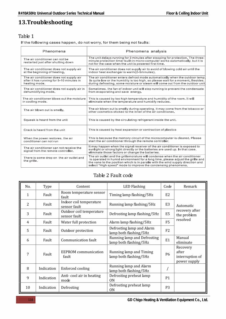
R410A50Hz Universal Outdoor Series Technical Manual Floor & Ceiling Indoor Unit
116 GD Chigo Heating & Ventilation Equipment Co., Ltd.
13.Troubleshooting
Table 1
Table 2 Fault code
No. Type Content LED Flashing Code Remark
1 Fault Room temperature sensor fault Timing lamp flashing/5Hz E2
Automatic recovery after the problem resolved
2 Fault Indoor coil temperature sensor fault Running lamp flashing/5Hz E3
3 Fault Outdoor coil temperature sensor fault Defrosting lamp flashing/5Hz E5
4 Fault Water full protection Alarm lamp flashing/5Hz F5
5 Fault Outdoor protection Defrosting lamp and Alarm lamp both flashing/5Hz F2
6 Fault Communication fault Running lamp and Defrosting lamp both flashing/5Hz E1 Manual
eliminate
7 Fault EEPROM communication fault
Running lamp and Timing lamp both flashing/5Hz P6
Recovery after interruption of power supply
8 Indication Enforced cooling Running lamp and Alarm lamp both flashing/5Hz /
9 Indication Anti- cool air in heating mode
Defrosting preheat lamp ON P1
10 Indication Defrosting Defrosting preheat lamp ON P3

R410A50Hz Universal Outdoor Series Technical Manual Outdoor unit
117 GD Chigo Heating & Ventilation Equipment Co., Ltd.
Part 3 Outdoor Units
1.Specification ......................................................................... 118
2.Dimensions ........................................................................... 120
3.Service Space ........................................................................ 122
4.Wiring Diagrams .................................................................... 123
5.Electric Characteristics .......................................................... 129
6.Operation Limits .................................................................... 130
7.Sound Levels ......................................................................... 131
8.Exploded View ...................................................................... 132

R410A50Hz Universal Outdoor Series Technical Manual Outdoor Unit
118 GD Chigo Heating & Ventilation Equipment Co., Ltd.
1.Specification
Notes: 1. Nominal cooling capacities are based on the following conditions: Indoor temp: 27°CDB, 19°CWB; Outdoor temp: 35°CDB; Equivalent ref. Piping: 7.5m(horizontal)
2. Nominal heating capacities are based on the following conditions: Indoor temp: 20°CDB; Outdoor temp: 7°CDB, 6°CWB; Equivalent ref. Piping: 7.5m(horizontal)
3. Actual noise level may differ, depending on the room structure, etc, since these noise values are from an anechoic room.
Model COU-18HR1 COU-24HR1 COU-36HR1 Outdoor power supply V/Ph/Hz 220~240/1/50 220~240/1/50 220~240/1/50
Cooling Capacity
Btu/h 18000 24000 36000 KW 5.3 7.1 10.5
Input W 1900 2400 3710 Rated current A 8.64 10.91 16.86
Heating Capacity
Btu/h 19800 26400 39600 KW 5.8 7.8 11.5
Input W 1690 2100 3310 Rated current A 7.68 9.55 15.05
Max. input consumption W 2500 2700 4800 Max. current A 11.36 12.27 21.82 Starting current A 40 49 112
Compressor
Model ASH232SV-C8LU ASH264RV-C8DU1 C-SBN301H5D Type ROTARY ROTARY SCROLL Brand HITACHI HITACHI SANYO Capacity Btu/h 18800 24000 36000 Input W 1900 2200 3950 Rated current(RLA) A 8.8 9.95 19.2 Locked rotor Amp(LRA) A 40 49 112
Thermal protector built-in built-in built-in Capacitor μF 60 55 60 Refrigerant oil ml 600 600 1700
Outdoor motor fan
Model YDK-38-6B YDK-60A-6F YKD-200-6 Input W 80 150 450 Capacitor μF 2.5 4 10 Speed r/min 920 850 800
Outdoor coil
Number of rows 2 2 1 Tube pitch x row pitch mm 25×21.65 25×21.65 25×21.65 Fin spacing mm 1.7 1.8 1.4 Fin type Hydrophilic Hydrophilic Hydrophilic Tube outside dia. and type mm
9.52 9.52 9.52 inner grooved inner grooved inner grooved
Coil size(W×H×D) mm 800×510×43.3 742×650×43.3 883.5×950×21.65
Number of circuits 4 5 3 Outdoor air flow m3/h 2800 3800 6000 Outdoor noise level dB(A) 53 65 65
Outdoor unit
Dimension(W×H×D) mm 866×535×304 930×700×370 1070×995×400
Packing(W×H×D) mm 920×585×335 990×770×410 1145×1120×475
Net/Gross weight kg 49/51 58/61 92/100 Refrigerant type/quantity g R410A/1200 R410A/1800 R410A/2100 Throttle part capillary capillary capillary Design pressure MPa 4.2 4.2 4.2 Outdoor power supply mm2 1.5 2.5 4
Refrigerant piping
Liquid side/Gas side mm φ6.35/φ12.7 Φ9.52/Φ15.88 Φ9.52/Φ19.05 Max. pipe length m 20 20 20 Max. high drop m 10 10 10
Ambient temp °C -7~43 -7~43 -7~43 Stuffing Quantity(20'/40'/40'HQ) 100/200/208 70/140/144 40/80/80

R410A50Hz Universal Outdoor Series Technical Manual Outdoor unit
119 GD Chigo Heating & Ventilation Equipment Co., Ltd.
Model COU-36HSR1 COU-48HSR1 COU-60HSR1 Outdoor power supply V/Ph/Hz 380~415/3/50 380~415/3/50 380~415/3/50
Cooling Capacity
Btu/h 36000 48000 60000 KW 10.5 14 16
Input W 3800 5000 5700 Rated current A 6.79 8.94 10.19
Heating Capacity
Btu/h 39600 52800 66000 KW 11.5 15.4 16.6
Input W 3600 5100 5800 Rated current A 6.44 9.12 10.37
Max. input consumption W 4900 6000 6600 Max. current A 8.76 10.73 11.8 Starting current A 48 66 70
Compressor
Model C-SBN303H8D C-SBN373H8D C-SBN453H8D Type SCROLL SCROLL SCROLL Brand SANYO SANYO SANYO Capacity Btu/h 3600 48100 56000 Input W 3650 4750 5750 Rated current(RLA) A 6.58 8.22 9.77 Locked rotor Amp(LRA) A 48 66 70
Thermal protector built-in built-in built-in Capacitor μF / / / Refrigerant oil ml 1700 1700 1700
Outdoor motor fan
Model YKD-200-6 YDK-60-6P3-1 YDK-60-6P3-1 Input W 450 170×2 170×2 Capacitor μF 10 4×2 4×2 Speed r/min 800 780 780
Outdoor coil
Number of rows 1 2 2 Tube pitch x row pitch mm 25×21.65 22×19.05 25×21.65
Fin spacing mm 1.4 1.6 1.6 Fin type Hydrophilic Hydrophilic Hydrophilic Tube outside dia. and type mm
9.52 7.94 9.52 inner grooved inner grooved inner grooved
Coil size(W×H×D) mm 883.5×950×21.65 1735×1280×38.1 1804×1250×43.3
Number of circuits 3 7 7 Outdoor air flow m3/h 6000 6100 6100 Outdoor noise level dB(A) 65 60 60
Outdoor unit
Dimension(W×H×D) mm 1070×995×400 911×1335×400 911×1335×400
Packing(W×H×D) mm 1145×1120×475 964×1445×475 964×1445×475 Net/Gross weight kg 92/100 96/107 96/107
Refrigerant type/quantity g R410A/2100 R410A/3600 R410A/4000 Throttle part capillary capillary capillary Design pressure MPa 4.2 4.2 4.2 Outdoor power supply mm2 1.5 2.5 2.5
Refrigerant piping
Liquid side/Gas side mm Φ9.52/Φ19.05 Φ9.52/Φ19.05 Φ9.52/Φ19.05 Max. pipe length m 20 20 20 Max. high drop m 10 10 10
Ambient temp °C -7~43 -7~43 -7~43 Stuffing Quantity(20'/40'/40'HQ) 40/80/80 32/64/64 32/64/64 Notes: 1. Nominal cooling capacities are based on the following conditions:
Indoor temp: 27°CDB, 19°CWB; Outdoor temp: 35°CDB; Equivalent ref. Piping: 7.5m(horizontal) 2. Nominal heating capacities are based on the following conditions:
Indoor temp: 20°CDB; Outdoor temp: 7°CDB, 6°CWB; Equivalent ref. Piping: 7.5m(horizontal) 3. Actual noise level may differ, depending on the room structure, etc, since these noise values are from an anechoic room.

R410A50Hz Universal Outdoor Series Technical Manual Outdoor unit
120 GD Chigo Heating & Ventilation Equipment Co., Ltd.
2.Dimensions
2.1 COU-18H
D=( 590)A=( 875)
B=( 370)
C=(
700)
E=(
334)
930
2.2 COU-24HR1

R410A50Hz Universal Outdoor Series Technical Manual Outdoor unit
121 GD Chigo Heating & Ventilation Equipment Co., Ltd.
2.3 COU-36HR1, COU-36HSR1
2.4 COU-48HR1, COU-60HR1

R410A50Hz Universal Outdoor Series Technical Manual Outdoor unit
122 GD Chigo Heating & Ventilation Equipment Co., Ltd.
3.Service Space
>30cm
>60cm
>30c
m
>1
50cm
(Wall or obstacle)
Air inlet
Air outlet
Air inlet
Maintain channel
>50c
m
Obstacle
Fix with bolt
Deep foundation
Necessary width
300mm is necessary between 2 outdoor units
300mm
M10 bolt
4pieces per unit

R410A50Hz Universal Outdoor Series Technical Manual Outdoor unit
123 GD Chigo Heating & Ventilation Equipment Co., Ltd.
4.Wiring Diagrams
4.1 COU-18HR1
Outdoor Pipe Sesor
YE/
GN
COM
PRES
SOR
C
COMPRESSOR
RS
RDFAN
FAN
CAP
ACIT
OR
OR
WH
RD
BL
4YE/
GN
3WH
4 WAY VALVE COIL
BL
BL
XT
BL1 2
BK
Over Loading Protector
BK
OR
CAP
ACIT
OR
TO INDOOR UNIT

R410A50Hz Universal Outdoor Series Technical Manual Outdoor unit
124 GD Chigo Heating & Ventilation Equipment Co., Ltd.
4.2 COU-24HR1
CR
S
NL3 541 2
BL
RD
BK
YE/
GN
HEA
TER
KM
BR
C
RD
BL OR
BK BL
TO POWERTO POWER
A1
BLBL
RD
C1
OR
RD
FMM
BL
CO
NN
EC
TOR
PL
CO
NN
EC
TOR
FT
CO
NN
EC
TOR
PH
A2
YE/
GN
4-W
AY V
ALVE
CO
IL
RD
TO IN
DO
OR
OU
TDO
OR
PIP
E SE
NSO
R
CONNECTOR
CO
NN
EC
TOR
TB
JUNCTION BOARD
~

R410A50Hz Universal Outdoor Series Technical Manual Outdoor unit
125 GD Chigo Heating & Ventilation Equipment Co., Ltd.
4.3 COU-36HR1
CR
S
NL 3 541 2
BL
RD
BK Y
E/G
N
HEATER
C
RD
BL OR
BK BL
TO INDOORTO POWER
A1
BL
BL
RD
C1
OR
RD
FMM
BL
CO
NN
EC
TOR
PL
CO
NN
EC
TOR
FT
CO
NN
EC
TOR
PH
A2
YE
/GN
4-W
AY
VA
LVE
CO
IL
RD
TO IN
DO
OR
OU
TDO
OR
PIP
E S
EN
SO
R
CONNECTOR
CO
NN
EC
TOR
TB2
JUNCTION BOARD
~
BK
TB1
BR

R410A50Hz Universal Outdoor Series Technical Manual Outdoor unit
126 GD Chigo Heating & Ventilation Equipment Co., Ltd.
4.4 COU-36HSR1
PLL1
KMA1
A2
M
YE/GN
UV
W
BKRD
RD
KM
TO POWER
BL
FM2
YE/GN
BK
INDOOR
L2 L3 N
HEATER
NT
SR
S3 S9
JUNCTION BOARD
WHBK
BL
C2
BROR
BL
BL
RDOR
BL
BL
PHFT
RDRD
RD
BKRD
WH
RD
2 3 4 51
OR
4-WAY VALVE COIL
BL
BL
TB2
2 3 4 51
INDOOR
OUTDOOR PIPE SENSOR
RD
UV
W
~3
TB1

R410A50Hz Universal Outdoor Series Technical Manual Outdoor unit
127 GD Chigo Heating & Ventilation Equipment Co., Ltd.
4.5 COU-48HSR1
PLL1
KM
A1A2
M
YE/GN
UV
W
BK
RD
RD
KM
TO POWER
WH
FM2
YE/GN
C1
BK
TO INDOOR
L2
L3 N
HEATER
NT
SR
S3 S9
JUNCTION BOARD
WH
BK
BL
FM1
YE/GN
C2
BR
OR
BL
BL
OR
RD
RD
OR
OR
BL
BL
BL
PH
FT
RD
RD
RD
BK
RD
WH
RD
2 3 4 51
OR
4-WAY VALVE COIL
BL
BL
TB
2 3 4 51
TO INDOOR
OUTDOOR PIPE SENSOR
RD
UV
W
~3

R410A50Hz Universal Outdoor Series Technical Manual Outdoor unit
128 GD Chigo Heating & Ventilation Equipment Co., Ltd.
4.6 COU-60HSR1
PLL1
KM
A1A2
M
YE/GN
UV
W
BK
RD
RD
KM
TO POWER
WH
FM2
YE/GN
C1
BK
TO INDOOR
L2
L3 N
HEATER
NT
SR
S3 S9
JUNCTION BOARD
WH
BK
BL
FM1
YE/GN
C2
BR
OR
BL
BL
OR
RD
RD
OR
OR
BL
BL
BL
PH
FT
RD
RD
RD
BK
RD
WH
RD
2 3 4 51
OR
4-WAY VALVE COIL
BL
BL
TB
2 3 4 51
TO INDOOR
OUTDOOR PIPE SENSOR
RD
UV
W
~3

R410A50Hz Universal Outdoor Series Technical Manual Outdoor unit
129 GD Chigo Heating & Ventilation Equipment Co., Ltd.
5.Electric Characteristics
Model Outdoor Unit
Hz Voltage Min. Max.
COU-18HR1 50 220~240V 198 254
COU-24HR1 50 220~240V 198 254
COU-36HR1 50 220~240V 198 254
COU-36HSR1 50 380~415V 342V 418V
COU-48HSR1 50 380~415V 342V 418V
COU-60HSR1 50 380~415V 342V 418V

R410A50Hz Universal Outdoor Series Technical Manual Outdoor unit
130 GD Chigo Heating & Ventilation Equipment Co., Ltd.
6.Operation Limits
Operation mode Outdoor temperature(℃) Room temperature(℃) Cooling operation 18~43 16~32 Heating operation -7~24 16~32
10 15 25 30 352015
20
25
30
35
40
45
Indoor temperature(℃ WB)
Out
door
tem
pera
ture
(℃ D
B)
STD
Cooling
10 15 25 30 3520-10
-5
0
5
10
15
20
Indoor temperature(℃ DB)
Out
door
tem
pera
ture
(℃ W
B)
STD
Heating
25

R410A50Hz Universal Outdoor Series Technical Manual Outdoor unit
131 GD Chigo Heating & Ventilation Equipment Co., Ltd.
7.Sound Levels
18kBtu/h-36kBtu/h 48kBtu/h ~ 60kBtu/h
Microphone
Outdoor Unit
H
1.0m
Note: H= 0.5 × height of outdoor unit Note: The point A is in the middle of the whole outdoor panel.
Model Noise level dB(A)
COU-18HR1 53 COU-24HR1 58 COU-36HR1 65
COU-36HSR1 65 COU-48HSR1 60 COU-60HSR1 60

R410A50Hz Universal Outdoor Series Technical Manual Outdoor unit
132 GD Chigo Heating & Ventilation Equipment Co., Ltd.
8.Exploded View
8.1 COU-18HR1
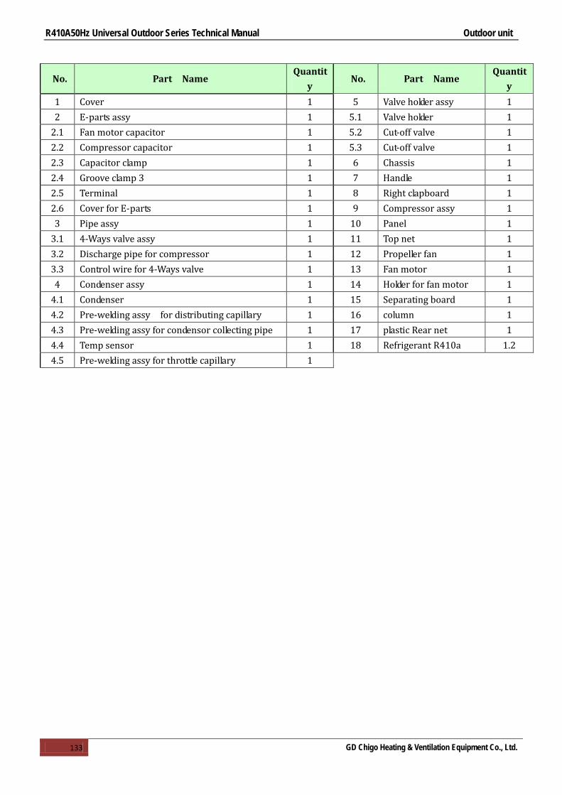
R410A50Hz Universal Outdoor Series Technical Manual Outdoor unit
133 GD Chigo Heating & Ventilation Equipment Co., Ltd.
No. Part Name Quantit
y No. Part Name
Quantity
1 Cover 1 5 Valve holder assy 1 2 E-parts assy 1 5.1 Valve holder 1
2.1 Fan motor capacitor 1 5.2 Cut-off valve 1 2.2 Compressor capacitor 1 5.3 Cut-off valve 1 2.3 Capacitor clamp 1 6 Chassis 1 2.4 Groove clamp 3 1 7 Handle 1 2.5 Terminal 1 8 Right clapboard 1 2.6 Cover for E-parts 1 9 Compressor assy 1 3 Pipe assy 1 10 Panel 1
3.1 4-Ways valve assy 1 11 Top net 1 3.2 Discharge pipe for compressor 1 12 Propeller fan 1 3.3 Control wire for 4-Ways valve 1 13 Fan motor 1 4 Condenser assy 1 14 Holder for fan motor 1
4.1 Condenser 1 15 Separating board 1 4.2 Pre-welding assy for distributing capillary 1 16 column 1 4.3 Pre-welding assy for condensor collecting pipe 1 17 plastic Rear net 1 4.4 Temp sensor 1 18 Refrigerant R410a 1.2 4.5 Pre-welding assy for throttle capillary 1

R410A50Hz Universal Outdoor Series Technical Manual Outdoor unit
134 GD Chigo Heating & Ventilation Equipment Co., Ltd.
8.2 COU-24HR1

R410A50Hz Universal Outdoor Series Technical Manual Outdoor unit
135 GD Chigo Heating & Ventilation Equipment Co., Ltd.
No. Part Name Quantity No. Part Name Quantity
1 Cover 1 12 Suction pipe assy 1 2 Sprung cotton for rear net 1 12.1 Suction pipe 1 3 E-parts assy 1 12.2 Low-pressure swicth 1
3.1 Capacitor clamp 1 13 Compressor assy 1 3.2 Groove clamp 4# 1 13.1 Compressor assy 1 3.3 Cover for E-parts 1 13.2 Rubber foot for compressor 1 3.4 Patching board 1 14 Maintenance panel 1 3.5 Terminal 1 15 Front top net 1 3.6 Compressor capacitor 1 16 Front panel 1 3.7 Fan motor capacitor 1 17 Propeller fan 1 3.8 Contactor 1 18 Fan motor 1 4 Right clapboard 1 19 Holder for fan motor 1 5 Handle 1 20 Chassis 1 6 Valve holder 1 21 Separating board 1 7 Cut-off valve 1 22 Handle 1 8 Cut-off valve 1 23 Left clapboard 1 9 Pre-welding assy for throttle capillary 1 24 Condenser assy 1
10 4-Ways valve assy 1 24.1 Condenser 1
10.1 4-Ways valve assy 1 24.2 condensor collecting pipe assy 1
10.2 Control wire for 4-Ways valve 1 24.3 distributing capillary assy 1 11 Discharge pipe assy 1 24.4 Temp sensor 1
11.1 Discharge pipe 1 25 Rear net 1 11.2 High-pressure swicth 1 26 Refrigerant R410a 1.8kg 11.3 Discharge temp sensor 1

R410A50Hz Universal Outdoor Series Technical Manual Outdoor unit
136 GD Chigo Heating & Ventilation Equipment Co., Ltd.
8.3 COU-36HR1

R410A50Hz Universal Outdoor Series Technical Manual Outdoor unit
137 GD Chigo Heating & Ventilation Equipment Co., Ltd.
No. Part Name Quantity No. Part Name Quantit
y 1 Cover 1 9.2 High-pressure swicth 1 2 Rear net 1 9.3 Discharge temp sensor 1 3 E-parts assy 1 10 4-Ways valve assy 1
3.1 Fan motor capacitor 1 10.1 4-Ways valve assy 1 3.2 Compressor capacitor 1 10.2 Control wire for 4-Ways valve 1 3.3 Contactor 1 11 Compressor 1 3.4 Terminal 1 12 Suction pipe for compressor 1 3.5 Terminal 1 13 Vapor-liquid seperator 1 3.6 Cover for E-parts 1 14 Maintenance board assy 1 3.7 Patchboard 1 14.1 Maintenance board 1 3.8 Protection cap 2 14.2 Handle 1 3.9 Capacitor clamp 1 15 Front panel assy 1
3.10 Groove clamp 4 1 15.1 Panel 1 4 Right clapboard assy 1 15.2 Top net 1
4.1 Right clapboard 1 16 Propeller fan 1 4.2 Handle 1 17 Fan motor 1 5 Valve holder assy 1 18 Holder for fan motor 1
5.1 Valve holder 1 19 Separating board 1 5.2 Cut-off valve 1 20 Chassis 1 5.3 Cut-off valve DN16 1 21 Left clapboard 1 6 throttle capillary Pre-welding assy 1 22 Condenser assy 1 7 Discharge pipe B for compressor 1 22.1 Condenser 1
8 compressor suction pipe B Pre-welding assy 1 22.2 condensor collecting pipe Pre-welding
assy 1
8.1 compressor Suction pipe B 1 22.3 distributing capillary Pre-welding assy 1 8.2 Low-pressure switch 1 22.4 Temp sensor 1
9 Pre-welding assy for discharge pipe A 1 23 Refrigerant R410a 2.1kg
9.1 Discharge pipe A for compressor 1
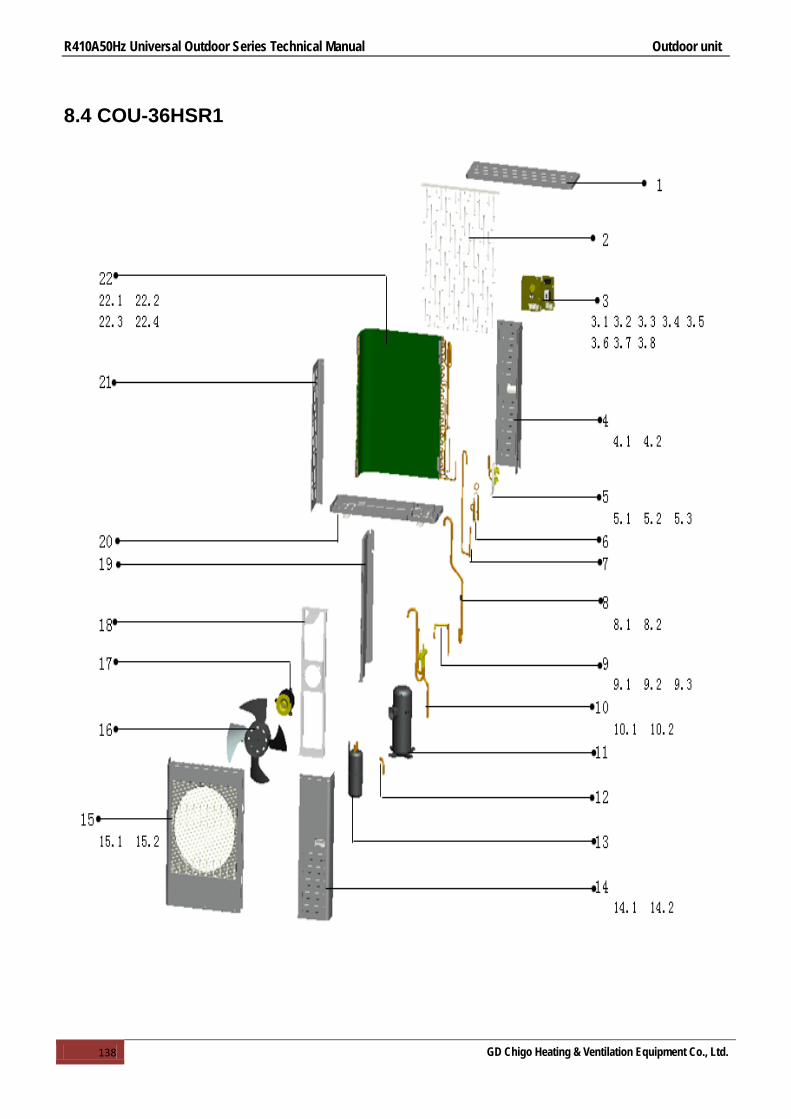
R410A50Hz Universal Outdoor Series Technical Manual Outdoor unit
138 GD Chigo Heating & Ventilation Equipment Co., Ltd.
8.4 COU-36HSR1

R410A50Hz Universal Outdoor Series Technical Manual Outdoor unit
139 GD Chigo Heating & Ventilation Equipment Co., Ltd.
No. Part Name Qty No. Part Name Qty 1 Cover 1 9.3 Discharge temp sensor 1 2 Rear net 1 10 4-Ways valve assy 1 3 E-parts assy 1 10.1 4-Ways valve assy 1
3.1 Fan motor capacitor 1 10.2 Control wire for 4-Ways valve 1 3.2 Contactor 1 11 Compressor 1 3.3 Terminal 1 12 Suction pipe for compressor 1 3.4 Terminal 1 13 Vapor-liquid seperator 1 3.5 Cover for E-parts 1 14 Maintenance board assy 1 3.6 Patch board 1 14.1 Maintenance board 1 3.7 Protection cap 2 14.2 Handle 1 3.8 Groove clamp 4 1 15 Front panel assy 1 4 Right clapboard assy 1 15.1 Panel 1
4.1 Right clapboard 1 15.2 Top net 1 4.2 handle 1 16 Propeller fan 1 5 Valve holder assy 1 17 Fan motor 1
5.1 Valve holder 1 18 Holder for fan motor 1 5.2 Cut-off valve 1 19 Separating board 1 5.3 Cut-off valve DN16 1 20 Chassis 1 6 Pre-welding assy for throttle capillary 1 21 Left clapboard 1 7 Discharge pipe B for compressor 1 22 Condenser assy 1
8 Pre-welding assy for compressor suction pipe B 1 22.1 Condenser 1
8.1 Suction pipe B for compressor 1 22.2 condensor collecting pipe Pre-welding assy 1
8.2 Low-pressure swicth 1 22.3 distributing capillary Pre-welding assy 1 9 Pre-welding assy for discharge pipe A 1 22.4 Temp sensor 1
9.1 Discharge pipe A for compressor 1 23 Refrigerant R410a 2.1kg 9.2 High-pressure switch 1

R410A50Hz Universal Outdoor Series Technical Manual Outdoor unit
140 GD Chigo Heating & Ventilation Equipment Co., Ltd.
8.5 COU-48HR1 , COU-60HR1

R410A50Hz Universal Outdoor Series Technical Manual Outdoor unit
141 GD Chigo Heating & Ventilation Equipment Co., Ltd.
No
. Part Name Quantity No. Part Name Quantit
y 1 Cover 1 17.1 Fan motor support 1 2 Rear clapboard 1 17.2 Joint board for fan motor support 1 3 Rear clapboard for valve 1 18 Chassis weld parts 1 4 High-pressure valve joint tube assy 1 19 Compressor foot cover 1 5 Discharge pipe assy 1 20 Separating board 1
5.1 Discharge pipe 1 21 Valve holder 1 5.2 High-pressure swicth 1 21.1 Valve holder 1 5.3 Discharge temp sensor 1 21.2 Cut-off valve DN8 1 6 4-Way valve assy 1 21.3 Cut-off valve DN16 1
6.1 4-Way valve assy 1 22 column 1 6.2 Control wire for 4-Ways valve 1 23 Condenser assy 1 7 Suction pipe assy 1 23.1 Condenser 1
7.1 Suction pipe 1 23.2 Condensor collecting pipe assy 1 7.2 Low-pressure swicth 1 23.3 Distributing capillary assy 1 8 Vapor-liquid seperator 1 23.4 Temp sensor 1 9 Compressor 1 24 E-parts assy 1
10 Right clapboard 1 24.1 Installation board for E-parts 1 11 Right clapboard for valve 1 24.2 Sequence protector 1 12 Top net 2 24.3 Contactor 1 13 Handle 3 24.4 Fan motor capacitor 1 14 Front panel 1 24.5 Terminal 1 15 Propeller fan 2 24.6 Groove clamp 2 16 Asynchronous motor 2 25 Plastic rear net 1 17 Fan motor support 1 26 Refrigerant R410a 3.6kg
R410A50Hz Universal Outdoor Series Technical Manual Installation
142 GD Chigo Heating & Ventilation Equipment Co., Ltd.
Part 4 Installation
1.Precaution on Installation ..................................................... 143
2.Vacuum Dry and Leakage Checking ........................................ 144
3.Additional Refrigerant Charge ............................................... 146
4.Water Drainage ..................................................................... 147
5.Insulation Work ..................................................................... 150
6.Test Operation ....................................................................... 152
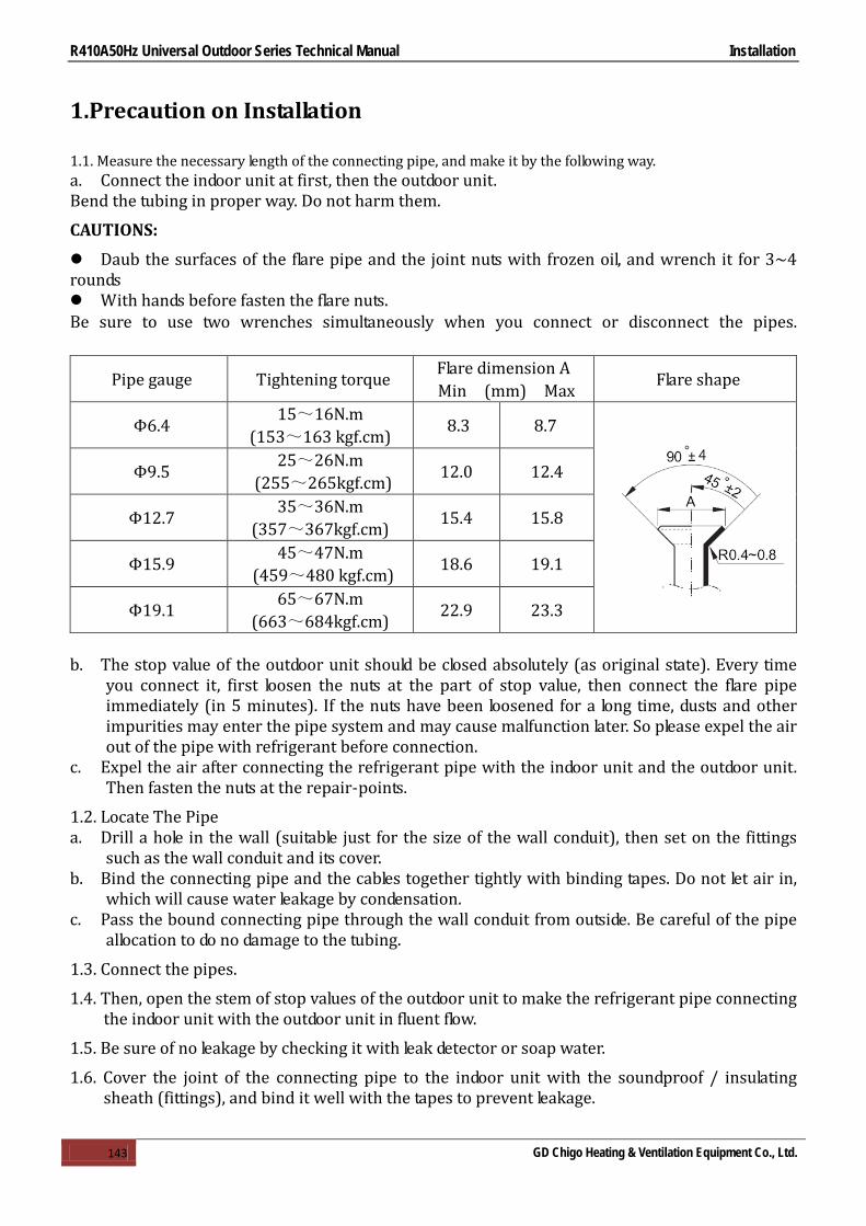
R410A50Hz Universal Outdoor Series Technical Manual Installation
143 GD Chigo Heating & Ventilation Equipment Co., Ltd.
1.Precaution on Installation
1.1. Measure the necessary length of the connecting pipe, and make it by the following way. a. Connect the indoor unit at first, then the outdoor unit. Bend the tubing in proper way. Do not harm them.
CAUTIONS:
Daub the surfaces of the flare pipe and the joint nuts with frozen oil, and wrench it for 3~4 rounds With hands before fasten the flare nuts. Be sure to use two wrenches simultaneously when you connect or disconnect the pipes.
Pipe gauge Tightening torque Flare dimension A Min (mm) Max Flare shape
Φ6.4 15~16N.m (153~163 kgf.cm) 8.3 8.7
Φ9.5 25~26N.m (255~265kgf.cm) 12.0 12.4
Φ12.7 35~36N.m (357~367kgf.cm) 15.4 15.8
Φ15.9 45~47N.m (459~480 kgf.cm) 18.6 19.1
Φ19.1 65~67N.m (663~684kgf.cm) 22.9 23.3
b. The stop value of the outdoor unit should be closed absolutely (as original state). Every time
you connect it, first loosen the nuts at the part of stop value, then connect the flare pipe immediately (in 5 minutes). If the nuts have been loosened for a long time, dusts and other impurities may enter the pipe system and may cause malfunction later. So please expel the air out of the pipe with refrigerant before connection.
c. Expel the air after connecting the refrigerant pipe with the indoor unit and the outdoor unit. Then fasten the nuts at the repair-points.
1.2. Locate The Pipe a. Drill a hole in the wall (suitable just for the size of the wall conduit), then set on the fittings
such as the wall conduit and its cover. b. Bind the connecting pipe and the cables together tightly with binding tapes. Do not let air in,
which will cause water leakage by condensation. c. Pass the bound connecting pipe through the wall conduit from outside. Be careful of the pipe
allocation to do no damage to the tubing.
1.3. Connect the pipes.
1.4. Then, open the stem of stop values of the outdoor unit to make the refrigerant pipe connecting the indoor unit with the outdoor unit in fluent flow.
1.5. Be sure of no leakage by checking it with leak detector or soap water.
1.6. Cover the joint of the connecting pipe to the indoor unit with the soundproof / insulating sheath (fittings), and bind it well with the tapes to prevent leakage.

R410A50Hz Universal Outdoor Series Technical Manual Installation
144 GD Chigo Heating & Ventilation Equipment Co., Ltd.
2.Vacuum Dry and Leakage Checking
2.1 Vacuum Dry: use vacuum pump to change the moisture (liquid) into steam (gas) in the pipe and discharge it out of the pipe to make the pipe dry. Under one atmospheric pressure, the boiling point of water(steam temperature) is 100℃. Use vacuum pump to make the pressure in the pipe near vacuum state, the boiling point of water falls relatively. When it falls under outdoor temperature, the moisture in the pipe will be vaporized.
2.2 Vacuum dry procedure
There are two methods of vacuum dry due to different construction environment: common vacuum dry, special vacuum dry.
①. Common vacuum dry procedure Vacuum dry (for the first time)---connect the all-purpose detector to the inlet of
liquid pipe and gas pipe, and run the vacuum pump more than two hours (the vacuum pump should be below -755mmHg)
If the pump can’t achieve below -755mmHg after pumping 2 hours, moisture or leakage point will still exist in the pipe. At this time, it should be pumped 1 hour more.
If the pump can’t achieve -755mmHg after pumping 3 hours, please check if there are some leakage points.
Vacuum placement test: place 1 hour when it achieves -755mmHg, pass if the vacuum watch shows no rising. If it rises, it shows there’s moisture or leakage point.
Vacuuming from liquid pipe and gas pipe at the same time. Sketch map of common vacuum dry procedure.

R410A50Hz Universal Outdoor Series Technical Manual Installation
145 GD Chigo Heating & Ventilation Equipment Co., Ltd.
②. Special vacuum dry procedure This vacuum dry method is used in the following conditions: There’s moisture when flushing the refrigerant pipe. Rainwater may enter into the pipe. Vacuum dry for the first time ······ 2h pumping
③. Vacuum destroy for the second time ······ Fill nitrogen to 0.5Kgf/cm2 Because nitrogen is for drying gas, it has vacuum drying effect during vacuum destroy. But if the moisture is too much, this method can’t dry thoroughly. So, please pay more attention to prevent water entering and forming condensation water.
④. Vacuum dry for the second time······1h pumping
Determinant: Pass if achieving below -755mmHg. If -755mmHg can’t be achieved in 2h, repeat procedure ③ and ④.
⑤. Vacuum placing test ······ 1h
⑥. Sketch map of special vacuum dry procedure

R410A50Hz Universal Outdoor Series Technical Manual Installation
146 GD Chigo Heating & Ventilation Equipment Co., Ltd.
3.Additional Refrigerant Charge
Caution ● Refrigerant cannot be charged until field wiring has been completed.
● Refrigerant may only be charged after performing the leak test and the vacuum pumping.
● When charging a system, care shall be taken that its maximum permissible charge is never exceeded, in view of the danger of liquid hammer.
● Charging with an unsuitable substance may cause explosions and accidents, so always ensure that the appropriate refrigerant is charged. ● Refrigerant containers shall be opened slowly.
● Always use protective gloves and protect your eyes when charging refrigerant.
The outdoor unit is factory charged with refrigerant. Calculate the added refrigerant according to the diameter and the length of the liquid side pipe of the outdoor unit/indoor unit
R(g) D(mm) L(m)
φ6.4 Φ9.5 Φ12.7
Less than 5m (One-way) — — — Added Refrigerant When Over 5m(One-way) 30g/m×(L-5) 65g/m×(L-5) 120g/m×(L-5)
Remark: R (g): Additional refrigerant to be charged L (m): The length of the refrigerant pipe (one-way) D (mm): Liquid side piping
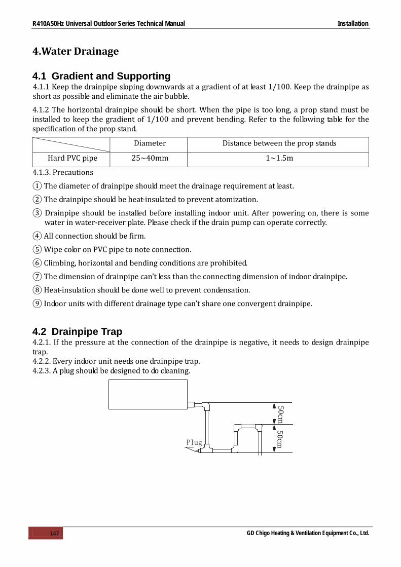
R410A50Hz Universal Outdoor Series Technical Manual Installation
147 GD Chigo Heating & Ventilation Equipment Co., Ltd.
4.Water Drainage
4.1 Gradient and Supporting 4.1.1 Keep the drainpipe sloping downwards at a gradient of at least 1/100. Keep the drainpipe as short as possible and eliminate the air bubble.
4.1.2 The horizontal drainpipe should be short. When the pipe is too long, a prop stand must be installed to keep the gradient of 1/100 and prevent bending. Refer to the following table for the specification of the prop stand.
Diameter Distance between the prop stands
Hard PVC pipe 25~40mm 1~1.5m
4.1.3. Precautions
① The diameter of drainpipe should meet the drainage requirement at least.
② The drainpipe should be heat-insulated to prevent atomization.
③ Drainpipe should be installed before installing indoor unit. After powering on, there is some water in water-receiver plate. Please check if the drain pump can operate correctly.
④ All connection should be firm.
⑤ Wipe color on PVC pipe to note connection.
⑥ Climbing, horizontal and bending conditions are prohibited.
⑦ The dimension of drainpipe can’t less than the connecting dimension of indoor drainpipe.
⑧ Heat-insulation should be done well to prevent condensation.
⑨ Indoor units with different drainage type can’t share one convergent drainpipe.
4.2 Drainpipe Trap 4.2.1. If the pressure at the connection of the drainpipe is negative, it needs to design drainpipe trap. 4.2.2. Every indoor unit needs one drainpipe trap. 4.2.3. A plug should be designed to do cleaning.
Plug
50cm50cm

R410A50Hz Universal Outdoor Series Technical Manual Installation
148 GD Chigo Heating & Ventilation Equipment Co., Ltd.
4.3 Upwards drainage (drain pump)
For Four-way cassette(compact)
For Four-way cassette
4.4 Convergent drainage 4.4.1. The number of indoor units should be as small as possible to prevent the traverse main pipe overlong. 4.4.2. Indoor unit with drain pump and indoor unit without drain pump should be in different drainage system.
4.4.3. Selecting the diameter
Number of connecting indoor units →Calculate drainage volume→Select the diameter Calculate allowed volume =Total cooling capacity of indoor units(HP)×2 (l/ hr)
Allowed volume(lean 1/50) (l/ hr) I.D. (mm) Thick Hard PVC ∽≤14 ¢25 3.0 Hard PVC 14<∽≤88 ¢30 3.5 Hard PVC 88<∽≤334 ¢40 4.0 Hard PVC 175<∽≤334 ¢50 4.5 Hard PVC 334<∽ ¢80 6.0

R410A50Hz Universal Outdoor Series Technical Manual Installation
149 GD Chigo Heating & Ventilation Equipment Co., Ltd.
4.5 Drainage test 4.5.1Drainage without drain pump
After finishing drainpipe installation, pour some water into the water receiver plate to check if the water flows smoothly.
4.5.2 Drainage with drain pump
① Poke the Water Level Switch, remove the cover, use water pipe to pour 2000ml water into the water receipt plate through the water inlet.
② Turn on the power to Cooling operation. Check the pump’s operation and switch on the Water Level Switch. Check the pump’s sound and look into the transparent hard pipe in the outlet at the same time to check if the water can discharge normally.
③ Stop the air conditioner running, turn off the power, and put back the cover.
Stop the air conditioner. After 3 minutes, check if it has abnormity. If the collocation of drainpipes is illogical, the water will flow back overfull, which will cause the alarm lamp flashes, even overflow from the water receipt plate.
Keep on pouring water until it gives an alarm signal for high water level, check if the pump drains water at once. If the water level can’t fall below the alarmed water level after 3 minutes, the air conditioner will stop. Turn off the power and drain the remained water, and then turn on the air conditioner.
Note: the drain stuff in the main water receipt plate is for maintenance. Stuff up the drain stuff to prevent water leakage.

R410A50Hz Universal Outdoor Series Technical Manual Installation
150 GD Chigo Heating & Ventilation Equipment Co., Ltd.
5.Insulation Work
5.1 Insulation material and thickness 5.1.1. Insulation material Insulation material should adopt the material which is able to endure the pipe’s temperature: no less than 70℃ in the high-pressure side, no less than 120℃ in the low-pressure side(For the cooling type machine, no requirements at the low-pressure side.)
Example: Heat pump type----Heat-resistant Polyethylene foam (withstand above 120℃) Cooling only type----Polyethylene foam (withstand above 100℃)
5.1.2. Thickness choice for insulation material Insulation material thickness is as follows:
Pipe diameter (mm) Adiabatic material thickness
Refrigerant pipe Φ6.4—Φ25.4 10mm
Φ28.6—Φ38.1 15mm Drainage pipe Inner diameterΦ20—Φ32 6mm
5.2 Refrigerant pipe insulation 5.2.1. Work Procedure ① Before laying the pipes, the non-jointing parts and non-connection parts should be heat insulated. ② When the gas proof test is eligible, the jointing area, expanding area and the flange area should
be heat insulated
5.2.2. Insulation for non-jointing parts and non-connection parts
wrong right
Gas pipe and liquid pipe should not be put together to insulate
Insulate the gas pipe (cooling only)
Insulate the gas pipe and liquid pipe

R410A50Hz Universal Outdoor Series Technical Manual Installation
151 GD Chigo Heating & Ventilation Equipment Co., Ltd.
For construction convenience, before laying pipes, use insulation material to insulate the pipes to be deal with, at the same time, at two ends of the pipe, remain some length not to be insulated, in order to be welded and check the leakage after laying the pipes.
5.2.3. Insulate for the jointing area, expanding area and the flange area ① Insulate for the jointing area, expanding area and the flange area should be done after checking
leakage of the pipes ② Make sure there’s no clearance in the joining part of the accessorial insulation material and
local preparative insulation material.
5.3 Drainage pipe insulation The connection part should be insulated, or else water will be condensing at the non-insulation part.
5.4 Note 5.4.1 The jointing area, expanding area and the flange area should be heat insulated after passing the pressure test 5.4.2 The gas and liquid pipe should be heat insulated individually, the connecting part should be heat insulated individually. 5.4.3 Use the attached heat-insulation material to insulate the pipe connections (pipes’ tie-in ,expand nut ) of the indoor unit .

R410A50Hz Universal Outdoor Series Technical Manual Installation
152 GD Chigo Heating & Ventilation Equipment Co., Ltd.
6.Test Operation
(1) The test operation must be carried out after the entire installation has been completed. (2) Please confirm the following points before the test operation. The indoor unit and outdoor unit are installed properly. Tubing and wiring are correctly completed. The refrigerant pipe system is leakage-checked. The drainage is unimpeded. The ground wiring is connected correctly. The length of the tubing and the added stow capacity of the refrigerant have been recorded. The power voltage fits the rated voltage of the air conditioner. There is no obstacle at the outlet and inlet of the outdoor and indoor units. The gas-side and liquid-side stop values are both opened. The air conditioner is pre-heated by turning on the power. (3) According to the user's requirement, install the remote controller when the remote controller's signal can reach the indoor unit smoothly. (4) Test operation Set the air conditioner under the mode of "COOLING" with the remote controller, and check the following points. Indoor unit Whether the switch on the remote controller works well. Whether the buttons on the remote controller works well. Whether the air flow louver moves normally. Whether the room temperature is adjusted well. Whether the indicator lights normally. Whether the temporary buttons works well. Whether the drainage is normal. Whether there is vibration or abnormal noise during operation. Outdoor unit Whether there is vibration or abnormal noise during operation. Whether the generated wind, noise, or condensed of by the air conditioner have influenced
your neighborhood. Whether any of the refrigerant is leaked.

R410A50Hz Universal Outdoor Series Technical Manual control
124 GD Chigo Heating & Ventilation Equipment Co., Ltd.
Part 5 Control
1.Wireless Remote Controller .................................................. 125
2.Wire Controller ..................................................................... 128
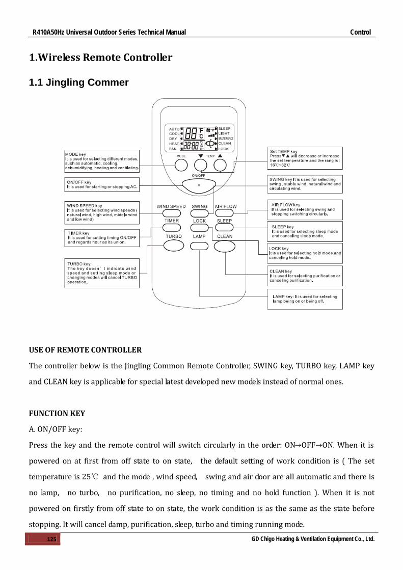
R410A50Hz Universal Outdoor Series Technical Manual Control
125 GD Chigo Heating & Ventilation Equipment Co., Ltd.
1.Wireless Remote Controller
1.1 Jingling Commer
USE OF REMOTE CONTROLLER
The controller below is the Jingling Common Remote Controller, SWING key, TURBO key, LAMP key
and CLEAN key is applicable for special latest developed new models instead of normal ones.
FUNCTION KEY
A. ON/OFF key:
Press the key and the remote control will switch circularly in the order: ON→OFF→ON. When it is
powered on at first from off state to on state, the default setting of work condition is ( The set
temperature is 25℃ and the mode , wind speed, swing and air door are all automatic and there is
no lamp, no turbo, no purification, no sleep, no timing and no hold function ). When it is not
powered on firstly from off state to on state, the work condition is as the same as the state before
stopping. It will cancel damp, purification, sleep, turbo and timing running mode.

R410A50Hz Universal Outdoor Series Technical Manual control
126 GD Chigo Heating & Ventilation Equipment Co., Ltd.
B. MODE key:
Press the key to switch modes in the order: automatic cooling →dehumidify →heating →ventilating
→automatic.
C. "▼" key:
In dehumidifying mode and automatic mode, pressing the key cannot change the temperature. In
other mode, press the key once and the temperature will decrease 1℃ in the order: 32℃→31℃
→…→17℃→16℃ .
D. "▲"key:
In dehumidifying mode and automatic mode, pressing the key cannot change the temperature. In
other mode, press the key once and the temperature will increase 1℃ in the order: 16℃→17℃
→…→31℃→32℃.
E. SWING key:
In dehumidifying mode, the swing mode is in the stable wind mode without change. In other mode,
press the key to switch modes in the order: swing → stable wind→ natural wind →swing
F. AIR FLOW key:
The default air flow is in the swing mode when starting firstly and press the key to switch modes in
the order: swing →stop →swing.
G. WIND SPEED key:
The default wind speed is in the automatic wind mode when starting firstly. The remote control
won't react by pressing the key because the wind speed can’t be adjusted and in low speed in
dehumidifying mode. In other mode, press the key to switch modes in the order:
Automatic wind→ high speed →middle speed→ low speed →automatic wind
H. TIMER key:
The default mode is in no timing state, press the key to set timing time with hour as its union. The
switch order is: 1H→2H→…→24H→cancel→1H…. Press the key to set timing starting in the off
state and set timing stopping in the on state. After setting timing function, the time keeps decreasing
per hour until the time decreasing to the timing on or timing off and the timing display will be
cancelled at the same time. Pressing MODE key can’t cancel timing in timing mode which will send
out the order of timing time by pressing other key.
I. TURBO key:

R410A50Hz Universal Outdoor Series Technical Manual control
127 GD Chigo Heating & Ventilation Equipment Co., Ltd.
The default state for the control is no turbo and the key don’t work in the automatic mode,
dehumidifying mode and ventilating mode (It will not display any contents and not send out any
codes). The control, however, will switch between on and off by pressing the key in other mode. The
wind speed isn’t indicated in turbo mode and it will be cancelled for changing modes and setting
sleep mode.
J. SLEEP key:
Press the key to switch modes in the order: sleep→ cancel sleep→ sleep. The sleep function won’t be
cancelled for changing modes. Press the key to set sleep mode and the wind speed will automatically
be switched to low speed and it can adjust the wind speed by pressing the WIND SPEED key (except
dehumidifying mode).
K. LOCK key:
The default state is in no LOCK key state, press the key to select modes in order: LOCK key →cancel
LOCK key→ LOCK key; In LOCK key mode, all keys except LOCK key of the remote control can’t work .
(NOTE: In LOCK key mode, the remote and operation panel of the unit both will be locked
automatically by pressing the key and press the key again, they will be unlocked. As for the split unit,
it only holds the control rather than urgent keys and the panel will make a reaction.)
L. LAMP key:
The default state is in no LAMP key state, press the key to select modes in order: LAMP key →cancel
LAMP key→ LAMP key; In LAMP key mode, pressing MODE key can’t cancel the show of LAMP key.
M. CLEAN key:
The default state is in no purification state, press the key to select modes in order: CLEAN →cancel
CLEAN→ CLEAN; In purification mode, pressing CLEAN key can’t cancel purification function.
Press the key when the remote control is closed, the control will switch modes in the order: CLEAN
→cancel CLEAN→ CLEAN; when you stop the unit and turn on the purification switch, except the
wind, the stable swing and air door swing speed aren’t adjusted.

R410A50Hz Universal Outdoor Series Technical Manual control
128 GD Chigo Heating & Ventilation Equipment Co., Ltd.
2.Wire Controller
2.1 ZKX-QE-01
Instructions for function:
1. Key function: In the panel, there are 9 keys and their function and defining are:
a. “ON/OFF” key- On running, press the key to stop AC; On standby, press it to start AC;
b. “MODE” key- The key works as the “MODE” key in the remote controller;
c. “SPEED” key- The key works as the “SPEED” key in the remote controller;
d. “TIMING” key- The key works as the “TIMING” key in the remote controller;

R410A50Hz Universal Outdoor Series Technical Manual control
129 GD Chigo Heating & Ventilation Equipment Co., Ltd.
e. Press “TIME +” and “TIME -” key to adjust the time. At the timing state, press “TIME +” key
once and the timing time indicated on the LCD will increase one hour; When it increases to 12 hours
and the time will stay at the value. Press “TIME-” key once and the timing time indicated on the
LCD will decrease one hour; When it decreases to 1hour and the time will stay at the value.
f. “TEST” key: No matter the unit is running or at the standby state, press the key and LCD will
indicate the model and the temperature of the indoor coil instead of timing state or set temperature.
Besides, “TEST” key has another function. Press the key and power on, the main panel of the wire
controller will begin to check itself and the display is distributed the whole screen of LCD and the
buzzer will utter three times. The display and self-inspection will be complete 2 minutes later.
2. Indicator light (red): There is a power indicator light in the main panel of the wire controller.
When the system has been supplied power, the red light will be on. When the system goes wrong,
the indicator light will flash and give an alarm and it will turn off after the system power-off.
3. Incepting terminal: It is used for accepting the signal of infrared remote controller.
4. Buzzer: The buzzer will utter three times when power-on and starting and it will utter twice when
pressing “TIME +” and “TIME -” key at the same time. When the controller accepts other signal, it
only utters once. 2.2 ZKX-PF-02

R410A50Hz Universal Outdoor Series Technical Manual control
130 GD Chigo Heating & Ventilation Equipment Co., Ltd.
Note: 1. Do not handle the button with nail or other sharp things, so as avoid the damages of operation panel. 2. Thanks to technical renovation, the operation panel or remote controller may be changed without further notice. 1. Operation mode: Operation method of COOL/DEHUMIDIFY/HEAT (VENT) 1) Press ON/OFF button to start unit. 2) Press MODE button to select desired mode Select VENT mode and the compressor stops. 3) Press temperature + / - button to set the desired room temperature. Room temperature setting
ranges from 18℃ to 29℃. 4) Press FAN button to select the desired high speed, mid speed or low speed of Fan. Fan works
only at low speed during DEHUMIDIFY mode. 5) Press ON/OFF again to stop. To protect the air conditioner from starting immediately after
stopping, the delayed start function will keep the air conditioner idle for 3 minutes before automatically starting it. Note: When the temperature of surroundings is less than 21℃ or more than 43℃, do not
operate the COOL mode. When the temperature of surroundings is less than -7℃ or more than 24℃, do not operate the HEAT mode. When the indoor temperature is less than 18℃, do not transformed to the DEHUMIDIFY mode. 2. Timing operation Timing OFF operation: Set the OFF time and the air conditioner will automatically stop at the set time. 1) While the air conditioner is running , press the TIMING button , and the air conditioner enters
timing OFF state, and "TIMING OFF"and "TIMING"lamps will be on. 2) Press + or - button to set the desired timing OFF time. The set time ranges From 1 to 12 hours.

R410A50Hz Universal Outdoor Series Technical Manual control
131 GD Chigo Heating & Ventilation Equipment Co., Ltd.
The green lamps on the display area show the set OFF time, that is, the time left to turn the unit off. The number of green lamps will decrease 1 hour every hour, and the rest lamps indicate the left hours.
3) To cancel the setting, press the TIMING button again. Under running state, only TIMING OFF function can be set.
Timing ON operation: Set the ON time and the air conditioner will automatically start at the set
time. 1) While the air conditioner is at standby state, press TIMING button, and the air conditioner
enters timing ON state, and "TIMING On"and "TIMING" lamps will be on. 2) Press + or - button to set the desired timing ON time .The set time ranges from1 to12 hours.
The green lamps on the display area show the set ON time, that is, the time left to turn the unit off. The number of green lamps wills decrease1hour every hour, and the rest lamps indicate the left hours.
3) To cancel the setting, press the TIMING button again. Under standby state, only TIMING ON function can be set.
3. Features of HEAT Mode Theory and Capacity 1) Air conditioner absorbs heat from outdoor air and transmits it indoor to heat the Indoor air.
For this heat bump heating theory, its heating capacity depends on the outdoor air temperature. 2) This heat cycling system raises the room temperature fast. 3) When the outdoor temperature is low, other heating facilities can be used together. DEFROST When the outdoor temperature is low and humidity is high, the outdoor heat exchanger will frost. Frost will affect heating efficiency. Under this circumstance, the DEFROST function automatically works and the heating operation will stop about 5-10 minutes for defrosting. 1) The fans of indoor and outdoor unit will both stop, and the HEAT lamp (green) will slowly flash
in defrosting. 2) Steam out of outdoor unit in defrosting is normal. 3) After DEFROST operation, the unit returns to HEAT mode.
SLEEP Use this mode to reduce operation sound when sleeping, etc.
Press the SLEEP button, the air flow sound from the indoor unit is decreased. Press the SLEEP again can release the mode.
NOTE: Use the sleep mode when you are going to bed, If this mode is used in the day, the capacity is
reduced since the ambient temperature is too high. During the operation of cooling, the room temperature will be raised gradually by 2℃(4℉)higher than the setting after the machine begins to operate in the sleeping mode. During the operation of heating mode, the room temperature will be dropped gradually 5℃(9℉)lower than the setting after the machine begins to operate in the sleeping mode.