service manual - relevant solutions sigma controller... · ˇ select the type of regulation in the...
TRANSCRIPT

SERVICE MANUALUSA
SIGMA CONTROLArticle---No.: 7.7000.0 / 7.7001.0
Index: 080801
GL---Nr.: BA---7.7000.0---00


Table of Contents
Chapter --- Page
i
1 Technical Specification 1 --- 1. . . . . . . . . . . . . . . . . . . . . . . . . . . . . . . . . . . . . . . . .
1.1 Power Supply 1 --- 1. . . . . . . . . . . . . . . . . . . . . . . . . . . . . . . . . . . . . . . . . . . . . . . . . . . . . .1.2 Sensors 1 --- 1. . . . . . . . . . . . . . . . . . . . . . . . . . . . . . . . . . . . . . . . . . . . . . . . . . . . . . . . . . .1.3 Hardware 1 --- 1. . . . . . . . . . . . . . . . . . . . . . . . . . . . . . . . . . . . . . . . . . . . . . . . . . . . . . . . . .1.4 Software 1 --- 1. . . . . . . . . . . . . . . . . . . . . . . . . . . . . . . . . . . . . . . . . . . . . . . . . . . . . . . . . . .
2 Safety Regulations 2 --- 2. . . . . . . . . . . . . . . . . . . . . . . . . . . . . . . . . . . . . . . . . . . . .
3 General 3 --- 3. . . . . . . . . . . . . . . . . . . . . . . . . . . . . . . . . . . . . . . . . . . . . . . . . . . . . . .
3.1 Brief description 3 --- 3. . . . . . . . . . . . . . . . . . . . . . . . . . . . . . . . . . . . . . . . . . . . . . . . . . . .3.2 Finding the best Type of Pressure Regulation 3 --- 4. . . . . . . . . . . . . . . . . . . . . . . . . .3.3 DUAL Control 3 --- 5. . . . . . . . . . . . . . . . . . . . . . . . . . . . . . . . . . . . . . . . . . . . . . . . . . . . . .3.4 QUADRO Control 3 --- 6. . . . . . . . . . . . . . . . . . . . . . . . . . . . . . . . . . . . . . . . . . . . . . . . . . .3.5 VARIO Control 3 --- 7. . . . . . . . . . . . . . . . . . . . . . . . . . . . . . . . . . . . . . . . . . . . . . . . . . . . . .
4 Operation 4 --- 9. . . . . . . . . . . . . . . . . . . . . . . . . . . . . . . . . . . . . . . . . . . . . . . . . . . . .
4.1 Control Panel 4 --- 9. . . . . . . . . . . . . . . . . . . . . . . . . . . . . . . . . . . . . . . . . . . . . . . . . . . . . . .4.2 Sigma Control 4 --- 9. . . . . . . . . . . . . . . . . . . . . . . . . . . . . . . . . . . . . . . . . . . . . . . . . . . . . .4.3 Emergency Stop Pushbutton 4 --- 9. . . . . . . . . . . . . . . . . . . . . . . . . . . . . . . . . . . . . . . . .4.4 Function Keys 4 --- 10. . . . . . . . . . . . . . . . . . . . . . . . . . . . . . . . . . . . . . . . . . . . . . . . . . . . . .4.4.1 Key functions 4 --- 11. . . . . . . . . . . . . . . . . . . . . . . . . . . . . . . . . . . . . . . . . . . . . . . . . . . . . . .4.5 Light Emitting Diodes (LEDs) and Plain Text Display 4 --- 12. . . . . . . . . . . . . . . . . . . . .4.5.1 LED functions 4 --- 13. . . . . . . . . . . . . . . . . . . . . . . . . . . . . . . . . . . . . . . . . . . . . . . . . . . . . .4.5.1.1 Display 4 --- 14. . . . . . . . . . . . . . . . . . . . . . . . . . . . . . . . . . . . . . . . . . . . . . . . . . . . . . . . . . . .4.6 Switching the Compressor Package On and Off 4 --- 15. . . . . . . . . . . . . . . . . . . . . . . .4.6.1 Switching on locally: 4 --- 15. . . . . . . . . . . . . . . . . . . . . . . . . . . . . . . . . . . . . . . . . . . . . . . .4.6.2 Switching off locally: 4 --- 15. . . . . . . . . . . . . . . . . . . . . . . . . . . . . . . . . . . . . . . . . . . . . . . .4.6.3 Switching on and off in remote (control center) 4 --- 15. . . . . . . . . . . . . . . . . . . . . . . . .4.6.4 Switching on and off with the timer 4 --- 15. . . . . . . . . . . . . . . . . . . . . . . . . . . . . . . . . . . .4.7 Resetting alarm messages 4 --- 15. . . . . . . . . . . . . . . . . . . . . . . . . . . . . . . . . . . . . . . . . . .4.8 Resetting Service Messages 4 --- 16. . . . . . . . . . . . . . . . . . . . . . . . . . . . . . . . . . . . . . . . .4.9 Alarm and Service Messages 4 --- 17. . . . . . . . . . . . . . . . . . . . . . . . . . . . . . . . . . . . . . . . .
5 SIGMA CONTROL Menus 5 --- 24. . . . . . . . . . . . . . . . . . . . . . . . . . . . . . . . . . . . . . .
5.1 Main menu 5 --- 24. . . . . . . . . . . . . . . . . . . . . . . . . . . . . . . . . . . . . . . . . . . . . . . . . . . . . . . . .5.2 Password Protection 5 --- 25. . . . . . . . . . . . . . . . . . . . . . . . . . . . . . . . . . . . . . . . . . . . . . . .5.3 Display and Setup Level 5 --- 25. . . . . . . . . . . . . . . . . . . . . . . . . . . . . . . . . . . . . . . . . . . . .5.4 Display Level 5 --- 25. . . . . . . . . . . . . . . . . . . . . . . . . . . . . . . . . . . . . . . . . . . . . . . . . . . . . . .
6 Display Level on the Control Panel 6 --- 28. . . . . . . . . . . . . . . . . . . . . . . . . . . . . .
6.1 Status Data 6 --- 28. . . . . . . . . . . . . . . . . . . . . . . . . . . . . . . . . . . . . . . . . . . . . . . . . . . . . . . .6.1.1 Display of Status Data 6 --- 29. . . . . . . . . . . . . . . . . . . . . . . . . . . . . . . . . . . . . . . . . . . . . .6.1.1.1 Messages 6 --- 29. . . . . . . . . . . . . . . . . . . . . . . . . . . . . . . . . . . . . . . . . . . . . . . . . . . . . . . . .6.1.1.2 Statistics 6 --- 30. . . . . . . . . . . . . . . . . . . . . . . . . . . . . . . . . . . . . . . . . . . . . . . . . . . . . . . . . . .6.1.1.3 Printout 6 --- 31. . . . . . . . . . . . . . . . . . . . . . . . . . . . . . . . . . . . . . . . . . . . . . . . . . . . . . . . . . . .

Table of Contents
Chapter --- Page
ii
6.2 Analog Data 6 --- 32. . . . . . . . . . . . . . . . . . . . . . . . . . . . . . . . . . . . . . . . . . . . . . . . . . . . . . . .6.2.1 Display of Analog Data 6 --- 33. . . . . . . . . . . . . . . . . . . . . . . . . . . . . . . . . . . . . . . . . . . . . .6.3 Hour Counter 6 --- 34. . . . . . . . . . . . . . . . . . . . . . . . . . . . . . . . . . . . . . . . . . . . . . . . . . . . . .6.3.1 Display of Hour Counter 6 --- 35. . . . . . . . . . . . . . . . . . . . . . . . . . . . . . . . . . . . . . . . . . . . .6.4 Service Hours 6 --- 36. . . . . . . . . . . . . . . . . . . . . . . . . . . . . . . . . . . . . . . . . . . . . . . . . . . . . .6.4.1 Display of Service Hours 6 --- 37. . . . . . . . . . . . . . . . . . . . . . . . . . . . . . . . . . . . . . . . . . . . .6.4.2 Resetting the service hour counter (maintenance interval counter) 6 --- 38. . . . . . . .
7 Display and Setup Level 7 --- 40. . . . . . . . . . . . . . . . . . . . . . . . . . . . . . . . . . . . . . . .
7.1 Panel Test 7 --- 40. . . . . . . . . . . . . . . . . . . . . . . . . . . . . . . . . . . . . . . . . . . . . . . . . . . . . . . . . .7.1.1 Display and setup of panel test 7 --- 41. . . . . . . . . . . . . . . . . . . . . . . . . . . . . . . . . . . . . . .7.1.1.1 Lamps test 7 --- 41. . . . . . . . . . . . . . . . . . . . . . . . . . . . . . . . . . . . . . . . . . . . . . . . . . . . . . . . .7.2 Timer 7 --- 42. . . . . . . . . . . . . . . . . . . . . . . . . . . . . . . . . . . . . . . . . . . . . . . . . . . . . . . . . . . . . .7.2.1 Display and setup of the timer 7 --- 43. . . . . . . . . . . . . . . . . . . . . . . . . . . . . . . . . . . . . . . .7.2.2 General description of the timer 7 --- 44. . . . . . . . . . . . . . . . . . . . . . . . . . . . . . . . . . . . . .7.2.2.1 The yearly schedule 7 --- 44. . . . . . . . . . . . . . . . . . . . . . . . . . . . . . . . . . . . . . . . . . . . . . . . .7.2.2.2 The weekly schedule 7 --- 44. . . . . . . . . . . . . . . . . . . . . . . . . . . . . . . . . . . . . . . . . . . . . . . .7.2.2.3 The daily schedule 7 --- 44. . . . . . . . . . . . . . . . . . . . . . . . . . . . . . . . . . . . . . . . . . . . . . . . . .7.3 Configuration 7 --- 48. . . . . . . . . . . . . . . . . . . . . . . . . . . . . . . . . . . . . . . . . . . . . . . . . . . . . . .7.3.1 Display and setup of configuration 7 --- 49. . . . . . . . . . . . . . . . . . . . . . . . . . . . . . . . . . . .7.3.1.1 Load/save data submenu 7 --- 49. . . . . . . . . . . . . . . . . . . . . . . . . . . . . . . . . . . . . . . . . . . .7.3.1.2 General submenu 7 --- 49. . . . . . . . . . . . . . . . . . . . . . . . . . . . . . . . . . . . . . . . . . . . . . . . . . .7.3.1.3 Password submenu 7 --- 50. . . . . . . . . . . . . . . . . . . . . . . . . . . . . . . . . . . . . . . . . . . . . . . . .7.3.1.4 Pressure settings submenu 7 --- 50. . . . . . . . . . . . . . . . . . . . . . . . . . . . . . . . . . . . . . . . . .7.3.1.5 Pressure control submenu 7 --- 51. . . . . . . . . . . . . . . . . . . . . . . . . . . . . . . . . . . . . . . . . . .7.3.1.6 Motor temperature submenu 7 --- 51. . . . . . . . . . . . . . . . . . . . . . . . . . . . . . . . . . . . . . . . .7.3.1.7 Function selection submenu 7 --- 51. . . . . . . . . . . . . . . . . . . . . . . . . . . . . . . . . . . . . . . . .7.4 PG Functions 7 --- 52. . . . . . . . . . . . . . . . . . . . . . . . . . . . . . . . . . . . . . . . . . . . . . . . . . . . . . .7.4.1 Display and setup of PG functions 7 --- 53. . . . . . . . . . . . . . . . . . . . . . . . . . . . . . . . . . . .7.5 Interfaces 7 --- 54. . . . . . . . . . . . . . . . . . . . . . . . . . . . . . . . . . . . . . . . . . . . . . . . . . . . . . . . . .7.5.1 Display and setup of interfaces 7 --- 55. . . . . . . . . . . . . . . . . . . . . . . . . . . . . . . . . . . . . . .7.6 History (Event Information Memory) 7 --- 56. . . . . . . . . . . . . . . . . . . . . . . . . . . . . . . . . . .7.7 List of Abbreviations 7 --- 57. . . . . . . . . . . . . . . . . . . . . . . . . . . . . . . . . . . . . . . . . . . . . . . . .

Technical Specification
1 --- 1
1 Technical Specification
1.1 Power Supply
Power supply for SIGMA CONTROL
Rated voltage 24 V DC (stabilized). . . . . . . . . . . . . . . . . . . . . . . .
Current 1.3 A (standard controller). . . . . . . . . . . . . . . . . . . . . . . . .
Current 2.5 A (with expansion card). . . . . . . . . . . . . . . . . . . . . . . .
Auxiliary voltage for sensors (from the controller)
Voltage 18 V DC. . . . . . . . . . . . . . . . . . . . . . . . . . . . . . . . . . . . . . . . .
All voltages are generated in the compressor package
1.2 Sensors
Pressure transducer:
Output signal of sensor 4 --- 20 mA. . . . . . . . . . . . . . . . . . . . . . . .
Connection two wire. . . . . . . . . . . . . . . . . . . . . . . . . . . . . . . . . . . . .
Resistance thermometer
Sensing resistor PT100 to DIN IEC 751. . . . . . . . . . . . . . . . . . . . .
Connection two wire. . . . . . . . . . . . . . . . . . . . . . . . . . . . . . . . . . . . .
1.3 Hardware- industrial computer with Intel9 processor
- analog inputs and outputs (0---20mA and PT100)
- 230/115 V relay outputs (floating contacts)
- 24 V common negative rail transistor outputs (short circuit and overload proof)
- 24 V common negative rail digital inputs
- internal undervoltage monitoring of 24 V supply
- internal temperature monitoring
- 3 serial interface:RS 232 (modem)RS 485 (master---slave control)Profibus DP
- real---time clock
- buffer battery for RAM and real---time clock
1.4 Software- real---time operating system
- soft PLC
- visualization software
- user software
Note

Safety
2 --- 2
2 Safety Regulations
- Do not pull out or push in components (plugs) on SIGMA CONTROL when the compressorpackage is operational. This can cause damage to the controller.
- Do not apply other voltages to the electronic outputs on the output plug pins (i.e. externalfeed via wire links, etc.).
- Do not run the compressor package with supplies removed from SIGMA CONTROL as irre-versible damage could occur (e.g. feed to the digital outputs with no power supply con-nected to the unit).

General
3 --- 3
3 General
3.1 Brief description
The SIGMA CONTROL electronic controller comprises an industrial computer with an Intel pro-cessor, a user interface with a background illuminated plain text display, keys, some with inte-grated LEDs, digital and analog inputs and outputs. Power to the controller is provided by a24 V DC power supply unit.
The controller is provided with a clear, easily understood user interface that allows call---up of in-formation or parameter settings to be made:
- LEDs indicate the most important operational states.
- various functions can be keyed.
- the plain text display provides information on current events to the user in the selected lan-guage
- an event information memory records the last 100 events with date and time, e.g. alarm,maintenance and operational messages.
SIGMA CONTROL controls, regulates, protects and monitors the compressor package.
The control function provides:
- automatic changeover from load to idle or standstill ensuring optimum utilization of the drivemotor, matched to the user’s current air demand.
- automatic start after a power supply failure.
The protective function provides:
- automatic shutdown at overload, excess pressure, excess temperature, etc., that is, faultsthat could cause to damage to the compressor package.
The monitoring function provides:
- punctual maintenance prompts for oil filter, air filter, V---belts, motor bearings, electrical com-ponents and other internal components. All these functions are monitored by the servicehour counter and maintenance due is displayed as warning or as service messages in theplain text display.
All important data can be transferred by the integrated software via the Profibus or the RS 232modem.
All parameters needed to operate KAESER screw compressor and vacuum packages are en-tered in SIGMA CONTROL. Depending on compressor model they are set up at the factory.These parameters can be displayed or changed in the software with the help of various menus orsub ---menus (see also chapter 5).
Parameter settings and changes are entered in the display and setup level of the software menuafter input of a password. At this level the type of drive, type of pressure regulation (Dual, Quadroor Vario control), the model and basic status according to model can be entered.

General
3 --- 4
3.2 Finding the best Type of Pressure Regulation
SIGMA CONTROL is provided with various types of regulation. This means that the compressorpackage can be operated at maximum efficiency depending on the user’s air demand.
� select the type of regulation in the ‘configuration’ menu.
� reset the ‘utilization from’ parameter in the ‘statistic’ menu.
� Run the compressor package for a longer period of time (at least four weeks, or more).
� Evaluate the ‘utilization from’ parameter.
Repeat this procedure for all types of pressure regulation.
DUAL control QUADRO control VARIO control
Utilization (%)
The type of pressure regulation with maximum utilization is the most effi-cient.
Note

General
3 --- 5
3.3 DUAL Control
pmaxp
min
Load
Idle
StandstillMot
orp
ower
Pre
ssur
e
Time
t1 t2
1 2 3 4 5
In DUAL Control (combined idle and start ---stop) the compressor normally runs in load, idle orstandstill.
The controller regulates the compressor package between load and idle.
If the compressor package runs in idle for longer than the preset period (1) to (2), for example t1= 6 min, the drive motor is stopped completely (2). When the lower switching point pmin (3) isreached the compressor package is automatically started again. Pressure rises to the upperswitching point pmax (4), and the compressor package switches to idle. If the pressure falls againwithin a shorter period (4) to (5), for example t2 = 3 min, to pmin (5) again then the compressor isautomatically switched from idle to load.

General
3 --- 6
3.4 QUADRO Control
1
Full load
StandstillMot
orp
ower
Pre
ssur
e pmaxpmin
tprise
tpdecay
Running periodIdle/standstill period
Run---on period
1111Time
Stop point for the running period or idle / standstill period
132 24
pmax upper switching point
pmin lower switching point
tprise pressure rise time (the time during which the air system pressure risesfrom the lower to the upper switching point)
tpdecay pressure decay time (the time during which the air system pressure decaysfrom the upper to the lower switching point)
4 5 11
Idle
Functional description
Two fixed periods --- the running period and idle/standstill period --- are taken as the criteriumfor selection of the operating mode of the compressor package when the air system pressurereaches the upper switching point. These two periods are set according to the maximum per-missible cut---in frequency of the drive motor.
The running period starts every time the compressor package is switched on. It lasts as long asthe drive motor runs and stops when the compressor package switches to standstill.
The idle/standstill period starts every time the operating mode changes from full load to idle. Itruns during idle and also when the compressor package is switched to standstill after the idleperiod. It stops when the compressor package switches to full load.
Every switching off point is delayed by the run---on period, during which time the compressorpackage vents.
The following switching cycles are possible:
- If the air system pressure decays to the lower switching point, the compressor packageswitches to full load (1) irrespective of its previous operating mode. If the drive motor was atstandstill the opening of the inlet valve is delayed to allow an unloaded compressor packagestart.
General
3 --- 7
- If the air system pressure rises to the upper switching point and the running period has al-ready expired, the compressor package is switched off after the run---on period has expired(2).
- If the air system pressure rises to the upper switching point before the running period hasexpired then the pressure decay time of the previous switching cycle is taken as the criteriumfor the selection of the operating mode:
-- If the pressure decay time tpdecay was longer than the period set for the idle/standstillperiod, the compressor package is switched to standstill after the run---on period has ex-pired (3).
-- If the pressure decay time tpdecay was shorter than the period set for the idle / standstillperiod, the idle mode is selected (4), that is, the inlet valve closes and the compressor isvented with running motor. When the running period expires the compressor packageswitches to standstill only after the run---on period has also expired (5).
3.5 VARIO Control
Functional Description:
In Vario Control the idle period is automatically extended or shortened depending on the numberof motor starts. The number of motor starts occurring during the preceding hour are recordedand evaluated.
The higher the motor switching frequency the longer the idle period.The lower the motor switching frequency the shorter the idle period.

General
3 --- 8

Operation
4 --- 9
4 Operation
4.1 Control Panel
1
2
1 SIGMA CONTROL panel2 Emergency Stop pushbutton
4.2 Sigma Control
Sigma Control (1) is fitted in the control cabinet in the compressor package and serves as thecontrol panel. It has 11 keys and 9 LEDs. Operation of the compressor package is determined bythe settings programmed into the controller.
4.3 Emergency Stop Pushbutton
The Emergency Stop pushbutton shuts down the compressor package immediately.
If the Emergency Stop pushbutton is pressed because of an existing hazard, then this must beeliminated before the compressor package is reset. To accomplish this the following proceduremust be carried out:
� Unlatch the Emergency Stop pushbutton by turning the button in the direction of the arrow.
� Acknowledge the alarm message on Sigma Control by pressing the acknowledge (reset)key.
Operation
4 --- 10
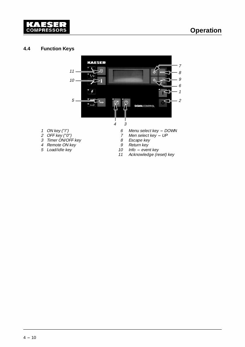
4.4 Function Keys
1
2
8
9
4 3
11
10
5
7
6
1 ON key (”I”) 6 Menu select key --- DOWN2 OFF key (”0”) 7 Men select key --- UP3 Timer ON/OFF key 8 Escape key4 Remote ON key 9 Return key5 Load/idle key 10 Info --- event key
11 Acknowledge (reset) key
Operation
4 --- 11
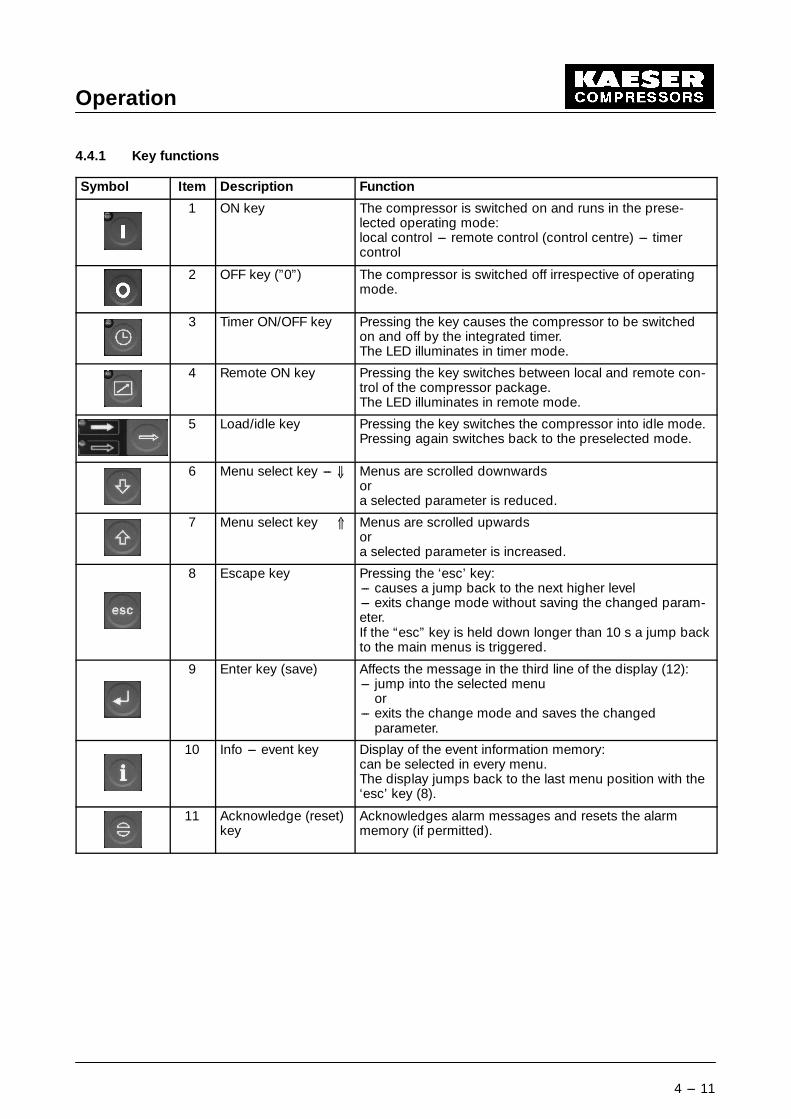
4.4.1 Key functions
Symbol Item Description Function
1 ON key The compressor is switched on and runs in the prese-lected operating mode:local control --- remote control (control centre) --- timercontrol
2 OFF key (”0”) The compressor is switched off irrespective of operatingmode.
3 Timer ON/OFF key Pressing the key causes the compressor to be switchedon and off by the integrated timer.The LED illuminates in timer mode.
4 Remote ON key Pressing the key switches between local and remote con-trol of the compressor package.The LED illuminates in remote mode.
5 Load/idle key Pressing the key switches the compressor into idle mode.Pressing again switches back to the preselected mode.
6 Menu select key --- Ç Menus are scrolled downwardsora selected parameter is reduced.
7 Menu select key Å Menus are scrolled upwardsora selected parameter is increased.
8 Escape key Pressing the ‘esc’ key:--- causes a jump back to the next higher level--- exits change mode without saving the changed param-eter.If the “esc” key is held down longer than 10 s a jump backto the main menus is triggered.
9 Enter key (save) Affects the message in the third line of the display (12):--- jump into the selected menu
or--- exits the change mode and saves the changed
parameter.
10 Info --- event key Display of the event information memory:can be selected in every menu.The display jumps back to the last menu position with the‘esc’ key (8).
11 Acknowledge (reset)key
Acknowledges alarm messages and resets the alarmmemory (if permitted).
Operation
4 --- 12
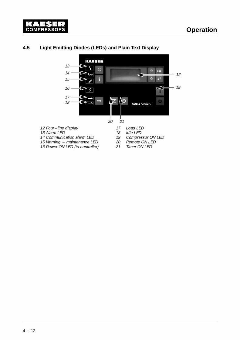
4.5 Light Emitting Diodes (LEDs) and Plain Text Display
12
13
19
14
15
16
1718
20 21
12 Four ---line display 17 Load LED13 Alarm LED 18 Idle LED14 Communication alarm LED 19 Compressor ON LED15 Warning --- maintenance LED 20 Remote ON LED16 Power ON LED (to controller) 21 Timer ON LED

Operation
4 --- 13
4.5.1 LED functions
Symbol Item Description Function
���EDU ���&(,1�7 �/$67 � S�
*HVDPW �������
/DVW ������
12 Four---line displaysee 4.5
Alpha numerical display with 4 lines with 16 characters(columns) each and green background illumination.
13 Alarm LED The red LED flashes if the compressor package is shutdown because of an alarm.If the alarm is acknowledged with the key (11), the LEDilluminates permanently. It extinguishes when the faultcausing the alarm is remedied and the alarm is reset.
14 Communicationalarm LED
The red LED illuminates if communication via the datainterface is interrupted.In remote mode the compressor package is automati-cally switched to local mode.If data communication returns the compressor pack-age is automatically switched to remote mode again.When the acknowledge key (11) is pressed, the LEDextinguishes if the alarm is no longer present.
15 Warning/mainte-nance LED
The yellow LED flashes when maintenance is due or ifthere is a maintenance warning.If the message is acknowledged with the key (11), theLED illuminates permanently until the maintenance iscompleted and (if necessary) the service counter isreset.
16* Power ON LED The green LED illuminates when power is available(main disconnect and automatic cutout for the controltransformer are both switched on and 24 V DC is pres-ent at the output of the power supply unit).
17* Load LED The green LED illuminates when the compressor isrunning under load and compressed air is being sup-plied.
18* Idle LED The green LED illuminates permanently when thecompressor is running but no compressed air is beingsupplied. The LED flashes if idle mode is selected withthe idle key (5).
19* Compressor ON LED
*Compressor instandby
The compressor is switched on.LEDs 17 and 18 must be taken into consideration todetermine the operational status of the compressorpackage:If both LEDs (16) and (19) are on-- and bothLEDs (17) and (18) are off, the package is at stand-still and in standby.It can start at any moment.
20 Remote ON LED The green LED illuminates when the compressor pack-age is in remote control mode.
21 Timer ON LED The green LED illuminates when the compressor pack-age is controlled by the timer.

Operation
4 --- 14
4.5.1.1 Display
The display (12, see chapter 4.5) used for entry and readout of data and is provided with fourlines of 16 characters each.
Example:
F
��� SVL ����F 5$03 PD[�SPD[ ��� SVL$03 PLQ�
Line 1 -- header
The current air system pressure and airend discharge temperature are displayed in the header.These values are always shown:
- in the main menu
- in configuration levels, in which parameter changes can be made even if the compressor isrunning.
The letters ‘R’, ‘S’ and ‘F’ in column 16 identify internal operational modes of the controller andare shown for servicing reasons. ‘R’ means, that the controller is in ‘RUN mode’ and is workingperfectly. If the letters ‘S’ or ‘F’ appear, there is an internal fault.
Line 2
The letter ‘i’ always appears in line 2, column 16, if information that can be called up with the infokey ‘i’ is available for text in line 3.
Line 3 -- active line
All actions, such as jumps to submenus, or changes to values are made in line 3. If it is possibleto jump to a submenu or if a parameter can be entered the ‘enter (§)’ sign is displayed incolumn 16.
Line 4
The signs ‘D9F’ appear in line 4, column 16 and indicate the direction in which the lines can bescrolled:
- D --- upwards scroll only
- 9 --- downwards scroll only
- F --- scroll in both directions
Operation
4 --- 15
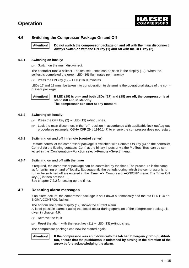
4.6 Switching the Compressor Package On and Off
Do not switch the compressor package on and off with the main disconnect.Always switch on with the ON key (1) and off with the OFF key (2).
4.6.1 Switching on locally:
� Switch on the main disconnect.
The controller runs a selftest. The test sequence can be seen in the display (12). When theselftest is completed the green LED (16) illuminates permanently.
� Press the ON key (1) --- LED (19) illuminates.
LEDs 17 and 18 must be taken into consideration to determine the operational status of the com-pressor package:
If LED (19) is on-- and both LEDs (17) and (18) are off, the compressor is atstandstill and in standby.The compressor can start at any moment.
4.6.2 Switching off locally:
� Press the OFF key (2) --- LED (19) extinguishes.
� Lock the main disconnect in the ”off” position in accordance with applicable lock out/tag outprocedures (example: OSHA CFR 29 § 1910.147) to ensure the compressor does not restart.
4.6.3 Switching on and off in remote (control center)
Remote control of the compressor package is switched with Remote ON key (4) on the controller.Control via the floating contacts ‘Cont’ at the binary inputs or via the Profibus ‘Bus’ can be se-lected in the ‘Configuration---Function select---Remote---Select’ menu.
4.6.4 Switching on and off with the timer
If required, the compressor package can be controlled by the timer. The procedure is the sameas for switching on and off locally. Subsequently the periods during which the compressor is torun or be switched off are entered in the ‘Timer ---> Compressor---ON/OFF’ menu. The Timer ONkey (3) is then pressed.See chapter 7.2.2 for setting up the timer.
4.7 Resetting alarm messages
If an alarm occurs, the compressor package is shut down automatically and the red LED (13) onSIGMA CONTROL flashes.
The bottom line of the display (12) shows the current alarm.A list of possible alarms (faults) that could occur during operation of the compressor package isgiven in chapter 4.9.
� Remove the fault.
� Reset the alarm with the reset key (11) --- LED (13) extinguishes.
The compressor package can now be started again.
If the compressor was shut down with the latched Emergency Stop pushbut-ton, ensure that the pushbutton is unlatched by turning in the direction of thearrow before acknowledging the alarm.
Attention!
Attention!
Attention!

Operation
4 --- 16
4.8 Resetting Service Messages
The yellow LED (15) on SIGMA CONTROL flashes when a maintenance routine is due.
Maintenance due is shown in the display (12).A list of service messages that can be displayed during operation is given in chapter 4.9).
� Carry out the maintenance.
� Acknowledge the service message with the reset key (11) --- LED (15) extinguishes.
A warning is given before maintenance is due. This serves the coordinationof maintenance and service personnel and provision of any service ma-terials(lubricants, spare parts, etc.) required.
When the associated maintenance is completed the remaining interval (3)must be reset to the predetermined maintenance interval (4).
� Reset the service hour counter, see chapter 6.4.2.
Note

Operation
4 --- 17
4.9 Alarm and Service Messages
Message2 Type1 Fault Remedy
A 0.6/A 0.7 A The conductor between output 0.6or output 0.7 and load circuit isshort---circuited.
Check load circuit, wiring and con-nections; change defective load cir-cuit
A 1.6/A 1.7 A The conductor between output 1.6or output 1.7 and load circuit isshort---circuited.
Check load circuit, wiring and con-nections; change defective load cir-cuit
access doors A The access doors were opened du-ring compressor operation.
Close the doors
ADT C W Initial warning:The maximum permissible airend dis-charge temperature (ADT) will bereached soon.
Make sure compressor spaceventilation is sufficient
Keep room temperature below 104�F
Clean cooler
Cooling air exhaust of compressorpackage too near the wall
Top ---off the oil
Replace oil filter
ADT A The maximum permissible airenddischarge temperature (ADT) wasexceeded.
Make sure compressor spaceventilation is sufficient
Keep room temperature below 104�F
Clean cooler
Cooling air exhaust of compressorpackage too near the wall
Top up the oil
Replace oil filter
AE1 nocont A There is no continuity in the conduc-tor between analog input 1 and theair main pressure transducer.
Check sensor, wiring and connec-tions;change defective sensor3
AE2 nocont A There is no continuity in the conduc-tor between analog input 2 and theinternal pressure transducer.
Check sensor, wiring and connec-tions;change defective sensor3
AE5 nocont A There is no continuity in the conduc-tor between analog input 5 and pres-sure transducer.
Check sensor, wiring and connec-tions;change defective sensor3
AE6 nocont A There is no continuity in the conduc-tor between analog input 6 and pres-sure transducer.
Check sensor, wiring and connec-tions;change defective sensor3
AI 3 nocont A There is no continuity in the conduc-tor between analog input 3 and theresistance thermometer measuringthe airend discharge temperature.
Check sensor, wiring and connec-tions; change defective sensor3
AI 4 nocont A There is no continuity in the conduc-tor between analog input 4 and theresistance thermometer measuringthe drive motor temperature.
Check sensor, wiring and connec-tions; change defective sensor3
1 AÆ alarm message WÆ warning message2 Symbols: high: C / too high: / low: 8 / too low:3 Contact authorized KAESER agency

Operation
4 --- 18
Message2 RemedyFaultType1
AI 7 nocont A There is no continuity in the conduc-tor between analog input 7 and sen-sor.
Check sensor, wiring and connec-tions; change defective sensor3
AI 8 nocont A There is no continuity in the conduc-tor between analog input 8 and sen-sor.
Check sensor, wiring and connec-tions; change defective sensor3
airend rotation A The airend rotors rotate in the wrongdirection.
Swap phases: power supply phasesL1 and L2 must be changed over
airend T dT/s A The nominal rate of rise of tempera-ture at the airend discharge (ADT)was exceeded (temperature measu-red with resistance thermometer).
Check airend and pipes to the air-end3
Top ---off the oil
air filter dp C W Initial warning:The air filter is clogged.
Order replacement parts
Prepare maintenance
air filter h C W Initial warning:the set service interval for the air filtercheck will expire soon.
Order replacement parts
Prepare maintenance
air filter h W The prescribed service interval forthe air filter has expired.
Clean air filter cartridge
Replace cartridge after fifth cleaning
AMP low W The air system pressure has fallenbelow the ‘low’ set value.
Measured with pressure transducer.
Check pressure transducer,conductors and connections;Replace defective sensor3
Air demand is too high; check con-sumers
bearings temp. A Overheating of the bearings on thedrive motor shaft.
Grease the drive motor bearings
Change bearings when damaged3
blowoff prot. W Initial warning:The set point of the pressure reliefvalve on the oil separator will be re-ached shortely.
Change oil separator cartridge
Check pressure transducer;change defective transducer3
blowoff prot. A The set point of the pressure reliefvalve on the oil separator has beenexceeded.
Change oil separator cartridge
Check transducer, wiring and con-nections;change defective transducer3
Check minimum pressure/checkvalve, control valve, inlet valve;change defective valve3
Open shut---off valve in the ventingline
buffer battery W The battery in the controller for reten-tion of data is discharged.
Change the controller battery3
comp. M I S Compressor shut down because ofdrive motor overload.
Investigate cause of shutdown;Reset reset overload trip
1 AÆ alarm message WÆ warning message2 Symbols: high: C / too high: / low: 8 / too low:3 Contact authorized KAESER agency

Operation
4 --- 19
Message2 RemedyFaultType1
comp. M T C W Initial warning:Drive motor very hot
(temperature sensed with PTC sen-sor and trip).
Ensure sufficient ventilation
Install exhaust fan
Drive motor dirty, clean motor
comp. M T PTC A Drive motor overheating
(temperature sensed with PTC sen-sor and trip).
Ensure sufficient ventilation
Install exhaust fan
Drive motor dirty, clean motor
comp. M T C W Initial warning:Drive motor very hot
(temperature sensed with PTC sen-sor and trip).
Ensure sufficient ventilation
Install exhaust fan
Drive motor dirty, clean motor
comp. M T A Drive motor overheating
(temperature sensed with resistancethermometer).
Ensure sufficient ventilation
Install exhaust fan
Drive motor dirty, clean motor
configuration W Invalid input. Check last setting
cooling water p A No cooling water pressure. Check throttling valve3
No inlet water pressure
No water shut---off valve
door open W The mainrtenance doors are open. Close the doors
E0.3 nocont A There is no continuity in the conduc-tor between input 0.3 and the direc-tion of rotation pressure switch.
Check pressure switch, wiring andconnections;change defective pressure switch3
E---comp h W Initial warning:The set service interval for electricalcomponents and electrical installa-tion check will expire soon.
Have electrical components checkedby a qualified electrician
E---comp h W The set service interval for electricalcomponents and electrical installa-tion check has expired.
Have electrical components checkedby a trained electrician
EMERGENCYSTOP
A The emergency stop pushbutton wasdepressed.
Unlatch and reset pushbutton
ext. load fault W Maximum set pressure of compres-sor exceeded during active ’remote’mode operation.
Check setting of the external loadsignal;change defective sensor3
ext. alarm 1 A An alarm message has been recei-ved from external equipment connec-ted to the controller.
Remove fault on external equipment
Change defective equipment
external maint. W A service message has been recei-ved from external equipment connec-ted to the controller.
Carry out maintenace on externalequipment
fan motor 2 A Fan motor 2 shut down because ofoverload.
Investigate cause; reset overload trip
1 AÆ alarm message WÆ warning message2 Symbols: high: C / too high: / low: 8 / too low:3 Contact authorized KAESER agency
Operation
4 --- 20
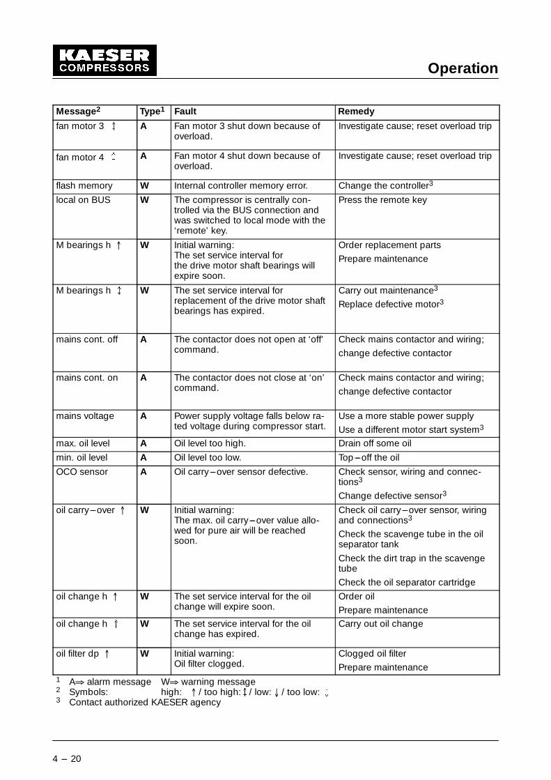
Message2 RemedyFaultType1
fan motor 3 A Fan motor 3 shut down because ofoverload.
Investigate cause; reset overload trip
fan motor 4 A Fan motor 4 shut down because ofoverload.
Investigate cause; reset overload trip
flash memory W Internal controller memory error. Change the controller3
local on BUS W The compressor is centrally con-trolled via the BUS connection andwas switched to local mode with the‘remote’ key.
Press the remote key
M bearings h C W Initial warning:The set service interval forthe drive motor shaft bearings willexpire soon.
Order replacement parts
Prepare maintenance
M bearings h W The set service interval forreplacement of the drive motor shaftbearings has expired.
Carry out maintenance3
Replace defective motor3
mains cont. off A The contactor does not open at ‘off’command.
Check mains contactor and wiring;
change defective contactor
mains cont. on A The contactor does not close at ‘on’command.
Check mains contactor and wiring;
change defective contactor
mains voltage A Power supply voltage falls below ra-ted voltage during compressor start.
Use a more stable power supply
Use a different motor start system3
max. oil level A Oil level too high. Drain off some oil
min. oil level A Oil level too low. Top ---off the oil
OCO sensor A Oil carry---over sensor defective. Check sensor, wiring and connec-tions3
Change defective sensor3
oil carry---over C W Initial warning:The max. oil carry---over value allo-wed for pure air will be reachedsoon.
Check oil carry---over sensor, wiringand connections3
Check the scavenge tube in the oilseparator tank
Check the dirt trap in the scavengetube
Check the oil separator cartridge
oil change h C W The set service interval for the oilchange will expire soon.
Order oil
Prepare maintenance
oil change h W The set service interval for the oilchange has expired.
Carry out oil change
oil filter dp C W Initial warning:Oil filter clogged.
Clogged oil filter
Prepare maintenance1 AÆ alarm message WÆ warning message2 Symbols: high: C / too high: / low: 8 / too low:3 Contact authorized KAESER agency

Operation
4 --- 21
Message2 RemedyFaultType1
oil filter h C W Initial warning:The set service interval for the oil fil-ter check will expire soon.
Order replacement parts
Prepare maintenance
oil filter h W The set service interval for the oil fil-ter check has expired.
Change the oil filter
oil---leak mon. h W Initial warning:The set service interval for the slidingring seal check will expire soon.
Carry out visual check of leak---oilcollector bottle
Empty leak---oil collector bottle
oil---leak mon. W The set service interval for the slidingring seal check has expired.
Empty leak---oil collector bottle
If the oil loss is high, change thesliding ring seal3
oil T/pressure A No changeover to load when the mi-nimum oil temperature is reached.
No changeover to load when the mi-nimum oil pressure is reached.
Check temperature switch, wiringand connections. Change defectiveswitch
Check pressure switch, wiring andconnections. Change defectiveswitch
oil too cold W The compressor will not start as oil istoo cold.(temperature measurement with PTCthermistor sensor and trip device).
Ambient temperature must be higherthan 38�F
Fit auxiliary heating system3
ON---OFF /h W The maximum permissible switchingfrequency of the drive motor was ex-ceeded during the last 60 minutes.
Extend idle period
Increase size of air receiver
Check pressure transducer;change defective transducer3
Increase diameter of pipeworkbetween compressor and air receiver
ON---OFF /day W The maximum permissible dailyswitching frequency of the drive mo-tor was exceeded during the last 24hours.
Extend idle period
Increase size of air receiver
Check pressure transducer;change defective transducer3
Increase diameter of pipework be-tween compressor and air receiver
PDT A Package discharge temperature be-low permissible value.
Two---speed cooling fan running athigh speed only --- switch to lowerspeed
PDT A Package discharge temperatureabove permissible value.
Two---speed cooling fan running atlow speed only --- switch to higherspeed
Check fan motor3
Check sensor, regulator3
Check frequency converter3
Clean cooler
Top ---off the oil1 AÆ alarm message WÆ warning message2 Symbols: high: C / too high: / low: 8 / too low:3 Contact authorized KAESER agency

Operation
4 --- 22
Message2 RemedyFaultType1
PDT 8 W Initial warning:Package discharge temperature istoo low.
Two---speed cooling fan running athigh speed only --- switch to lowerspeed
PDT C W Initial warning:Package discharge temperature toohigh.
Two---speed cooling fan running atlow speed only --- switch to higherspeed
Check fan motor3
Clean the cooler
Top ---off the oil
Profibus L2DP The bus connection via the Profi-bus---DP interface is interrupted.
Check bus wiring and plug, checkinterface configuration3
RAM memory W Internal RAM memory defective. Check controller3
separator dp C W Initial warning:The oil separator is clogged.
Order replacement parts
Prepare maintenance
separator h C W Initial warning:The set service interval for the oilseparator check expire soon.
Order replacement parts
Prepare maintenance
separator h W The set service interval for the oilseparator check has expired.
Change oil separator cartridge
separator T A The permissible air temperature atthe oil separator discharge was ex-ceeded(temperature measurement with PTCthermistor sensor and trip device).
Check trip device at oil separator airdischarge
Check sensor and wiring of tripdevice, change defective trip device
sh.cct AI3 A Short circuit in cable between ana-logue input 3 and airend dischargetemperature sensor.
Check sensor, wiring and connec-tions;change defective sensor3
sh.cct AI4 A Short circuit in cable between ana-logue input 4 and a sensor.
Check sensor, wiring and connec-tions;change defective sensor3
sh.cct AI7 A Short circuit in cable between ana-logue input 7 and a sensor.
Check sensor, wiring and connec-tions;change defective sensor3
sh.cct AI8 A Short circuit in cable between ana-logue input 8 and drive motor tem-perature sensor.
Check sensor, wiring and connec-tions;change defective sensor3
start voltage 8 W First power supply failure duringcompressor start.
Check wiring of power supply con-tactor
Use a more stable power supply
start voltage A Second power supply failure duringcompressor start.
Check wiring of power supply con-tactor
Use a more stable power supply
set output! The ‘ON’ key was pressed when thecontroller was in test mode ‘set out-put’ (PG functions).
Leave the ‘set output’ test mode
1 AÆ alarm message WÆ warning message2 Symbols: high: C / too high: / low: 8 / too low:3 Contact authorized KAESER agency

Operation
4 --- 23
Message2 RemedyFaultType1
temperature min. A The air temperature at the airend dis-charge (ADT) needed to start thecompressor is too low (temperaturemeasured with resistance thermome-ter).
Ambient temperature must be higherthan 38�F
Fit auxiliary heating system3
TRAP Interrupt C
V---belts h W Initial warning:The set service interval for the V---belts check will expire soon.
Carry out visual check
Order replacement parts
Prepare service routine
V---belts h W The set service interval for the V---belts check has expired.
Change and tension the V---belts
V---belt tens. h C W Initial warning:The set service interval for the V---belttension check will expire soon.
Carry out visual check
Prepare service routine
V---belt tens. h W The set service interval for the V---belttension check has expired.
Tension the V---belts, replace, ifrequired
V---belt tension W The V---belt tension is too low.
The V---belt tension is checked usinga limit switch.
Tension the V---belts
1 AÆ alarm message WÆ warning message2 Symbols: high: C / too high: / low: 8 / too low:3 Contact authorized KAESER agency

Menus --- General
5 --- 24
5 SIGMA CONTROL Menus
When the compressor package is switched on details of the software installed are initially dis-played on the Sigma Control. The software is then downloaded and the main menu appears inthe display.
5.1 Main menu
The main menu shows the current air main pressure, the airend discharge temperature, the typeof controller (via ON/OFF key, timer or remote operation), total hours run and load hours.
1
2
34 F
�� SVL ����F 521�NH\�ORDG�S�WRWDO ������KORDG ������K
1 Display of current outlet pressure and airend discharge temperature
2 Operational message (current state of the compressor package)
3 Total number of operating hours
3 Number of hours on load
The following information can be displayed in the second line (operational messages):
e.g. ON---key/load ---p1
pressure regulation p1 pressure range p1 (air main press.)p2 pressure range p2 (air main press.)RC Remote Contact (external load
contact)RB Remote Bus (external load signal)
state of air supplies
idle in idle runload on load
off standby: motor off, the motor startswhen air is demanded
change compressor state with:
Key ‘O’ and ‘I’ ---key on unit fronttimer internal timerRC Remote Contact
RB Remote Busstate of compressor ON compressor running
OFF compressor stoppedalarm a malfunction exists
The ‘esc’ key allows a jump---back to the main menu from all other menus and submenus.

Menus --- General
5 --- 25
5.2 Password Protection
Authority to access the menus and submenus is divided into several levels and protected bypassword.
When the controller is switched on the lowest level of access (level 0) is started. There are fourlevels available for the customer. The password for level 4 is to be found in the documents sup-plied with the compressor package or can be obtained from an authorized Kaeser distributor.
In level 4 the customer/user can create passwords for the first three levels (level 1 to level 3) andthus allow access to authorized persons. See chapter 7.3.1.3 for entry of the password.
5.3 Display and Setup Level
If the main menu is scrolled with the ‘D’ key, all menus in the display and setting level in whichprogrammed parameters can be changed are shown. These menus are:
- panel test
- timer
- configuration
- PG functions
- interfaces
- event information
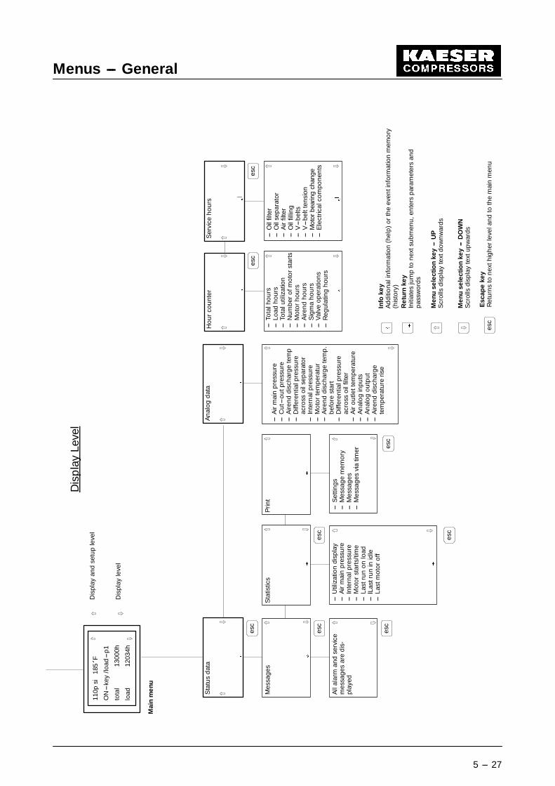
5.4 Display Level
If the main menu is scrolled with the ‘9’ key, all menus in the display level in which programmedparameters can only be read are shown. These menus are:
- status data
- measured data
- hour counter
- service hours
See following pages for overall list of menus and submenus in the display and setup level.
For an explanation of the abbreviated messages in the display, see list of abbreviations inchapter 7.7).

Menus --- General
5 --- 26
Tim
er
§
§
Pan
elte
st
---La
mp
ste
st---
Co
mp
ress
or
ON
/OF
F---
Dry
con
tact
---S
equ
ence
r---
Prin
t
§
Sys
tem
chec
kau
tom
atiic
5 sec.
Test
men
uVe
rsio
nm
enu
Mai
nm
enu
Dis
pla
yan
dse
tup
leve
l
Dis
pla
yle
vel
VIN
110p
si18
5�
F
ON
---ke
y/lo
ad---
p1
tota
l13
000h
load
1203
4h
PG
fun
ctio
ns
Co
nfig
ura
tion
§
§
§
Inte
rfac
es
---D
ata
bac
kup
---C
om
pre
sso
rm
od
el---
Gen
eral
---P
assw
ord
---P
ress
ure
setti
ng
s---
Typ
eo
fpre
ss.c
on
tro
l---
Tim
eva
lues
---A
iren
dd
isch
arg
ete
mp
.---
Driv
em
oto
rte
mp
.---
Fun
ctio
nse
lect
ion
---P
ow
ersw
itch
ing
---In
pu
t/o
utp
uts
tatu
s---
Set
ou
tpu
ts---
RS
232
---R
S48
5---
Pro
fibu
s
§
§
§
§
His
tory
(eve
nti
nfo
)
---T
he
last
100
even
tsar
est
ore
dan
dd
isp
laye
d
esc
esc
esc
esc
esc
esc
Ver
sio
nd
isp
lay
Har
dw
are
vers
ion
Op
.sys
tem
vers
ion
Co
mp
ress
or
vers
ion
L
Dis
pla
yan
dS
etup
Leve
l
esc
Menus --- General
5 --- 27
§
Ho
ur
cou
nte
r
---To
talh
ou
rs---
Load
ho
urs
---To
talu
tiliz
atio
n---
Nu
mb
ero
fmo
tor
star
ts---
Mo
tor
ho
urs
---A
iren
dh
ou
rs---
Sig
ma
ho
urs
---V
alve
op
erat
ion
s---
Reg
ula
ting
ho
urs
§
§
Ser
vice
ho
urs
---O
ilfil
ter
---O
ilse
par
ato
r---
Air
filte
r---
Oil
fillin
g---
V---
bel
ts---
V---
bel
tten
sio
n---
Mot
orbe
arin
gch
ange
---E
lect
rical
com
po
nen
ts
§
§
Info
key
Ad
diti
on
alin
form
atio
n(h
elp
)o
rth
eev
enti
nfo
rmat
ion
mem
ory
(his
tory
)R
etur
nke
yIn
itiat
esju
mp
ton
exts
ub
men
u,e
nte
rsp
aram
eter
san
dp
assw
ord
s
Men
use
lect
ion
key
---U
PS
cro
llsd
isp
lay
text
do
wn
war
ds
Men
use
lect
ion
key
---D
OW
NS
cro
llsd
isp
lay
text
up
war
ds
Esc
ape
key
Ret
urn
sto
nex
thig
her
leve
lan
dto
the
mai
nm
enu
§
Sta
tus
dat
a
Mes
sag
esS
tatis
tics
§
§
Prin
t
§
§
An
alo
gd
ata
All
alar
man
dse
rvic
em
essa
ges
are
dis
-p
laye
d
---U
tiliz
atio
nd
isp
lay
---A
irm
ain
pre
ssu
re---
Inte
rnal
pre
ssu
re---
Mo
tor
star
ts/t
ime
---La
stru
no
nlo
ad---
lLas
tru
nin
idle
---La
stm
oto
ro
ff
---S
ettin
gs
---M
essa
ge
mem
ory
---M
essa
ges
---M
essa
ges
via
timer
§
---A
irm
ain
pre
ssu
re---
Cu
t---o
utp
ress
ure
---A
iren
dd
isch
arg
ete
mp
---D
iffer
entia
lpre
ssu
reac
ross
oil
sep
arat
or
---In
tern
alp
ress
ure
---M
oto
rte
mp
erat
ur
---A
iren
dd
isch
arg
ete
mp
.b
efo
rest
art
---D
iffer
entia
lpre
ssu
reac
ross
oil
filte
r---
Air
ou
tlett
emp
erat
ure
---A
nal
og
inp
uts
---A
nal
og
ou
tpu
t---
Aire
nd
dis
char
ge
tem
per
atu
reris
e
Mai
nm
enu
110p
si18
5�
F
ON
---ke
y/lo
ad---
p1
tota
l13
000h
load
1203
4h
Dis
pla
yan
dse
tup
leve
l
Dis
pla
yle
vel
esc
esc
esc
esc
esc
esc
esc
esc
esc
L
Dis
pla
yLe
vel

Display Level
6 --- 28
6 Display Level on the Control Panel
Data on status and measurements, the hour counter and service hours are displayed at the dis-play level
6.1 Status Data
§
Status data
HVF
Messages Statistics
§§
Printout
§
HVF
--- All operational,alarm and servicemessages aredisplayed
HVF
--- Display of utilization--- Air main pressure--- Internal pressure--- Motor starts/time--- Last run on load--- Last run in idle--- Last motor stop--- Last alarm--- Last service--- Alarms activated--- Maintenance due--- Operational messages
activated
HVF
--- Parameters--- Message memory--- Messages--- Messages via
timer
§
HVF
HVF
HVF
Display Level
6 --- 29
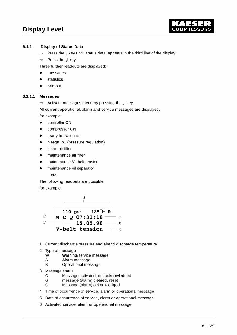
6.1.1 Display of Status Data
� Press the 9 key until ‘status data’ appears in the third line of the display.
� Press the § key.
Three further readouts are displayed:
- messages
- statistics
- printout
6.1.1.1 Messages
� Activate messages menu by pressing the § key.
All current operational, alarm and service messages are displayed,
for example:
- controller ON
- compressor ON
- ready to switch on
- p regn. p1 (pressure regulation)
- alarm air filter
- maintenance air filter
- maintenance V---belt tension
- maintenance oil separator
etc.
The following readouts are possible,
for example:
��� SVL ����F 5: & 4 ��������
��������9�EHOW WHQVLRQ
1
4
5
6
2
3
1 Current discharge pressure and airend discharge temperature
2 Type of messageW Warning/service messageA Alarm messageB Operational message
3 Message statusC Message activated, not acknowledgedG message (alarm) cleared, resetQ Message (alarm) acknowledged
4 Time of occurrence of service, alarm or operational message
5 Date of occurrence of service, alarm or operational message
6 Activated service, alarm or operational message

Display Level
6 --- 30
6.1.1.2 Statistics
� Activate display of statistics menu by pressing the § key.
Evaluated statistics are displayed,
for example:
- utilization
- minimum and maximum air main pressure (pmin or pmax)
- minimum and maximum internal pressure (pmin or Pmax)
- number of motor starts
- last run on load, last run in idle
- last alarm or service
- activated alarm, service and operational messages
The following readouts are possible,
for example:
1
2
34 F
��� SVL ����F 5$03 PD[��SPD[ ���SVL$03 PLQ��
1 Current discharge pressure and airend discharge temperature
2 Description of statistic
3 Value (percent, minimum or maximum value)
4 Next value
These statistics can be reset individually.
� Select submenu reset: no of the individual statistic by pressing the § key.
� Select the reset: yes with the D key.
� Press the § key.
� Exit the submenu with the ‘esc’ key.

Display Level
6 --- 31
6.1.1.3 Printout
� Activate the printout menu by pressing the § key.
All messages to be printed are displayed,
for example:
- settings
- message memory
- current messages
- messages via timer
The following readouts are possible,
for example
1
2
34 F
��� SVL ����F 5VHWWLQJVSULQW� QPVJ� PHPRU\
1 Current discharge pressure and airend discharge temperature
2 Message to be printed
3 Activation of printout
4 Next printout

Display Level
6 --- 32
6.2 Analog Data
§
Analog data
--- Air main pressure--- Cut---out pressure--- Airend discharge temp--- Differential pressure
across oil separator--- Internal pressure--- Motor temperature--- Airend discharge temp.
before start--- Differential pressure
across oil filter--- Air outlet temperature--- Analog inputs--- Analog output--- Airend discharge
temperature rise
Display Level
6 --- 33
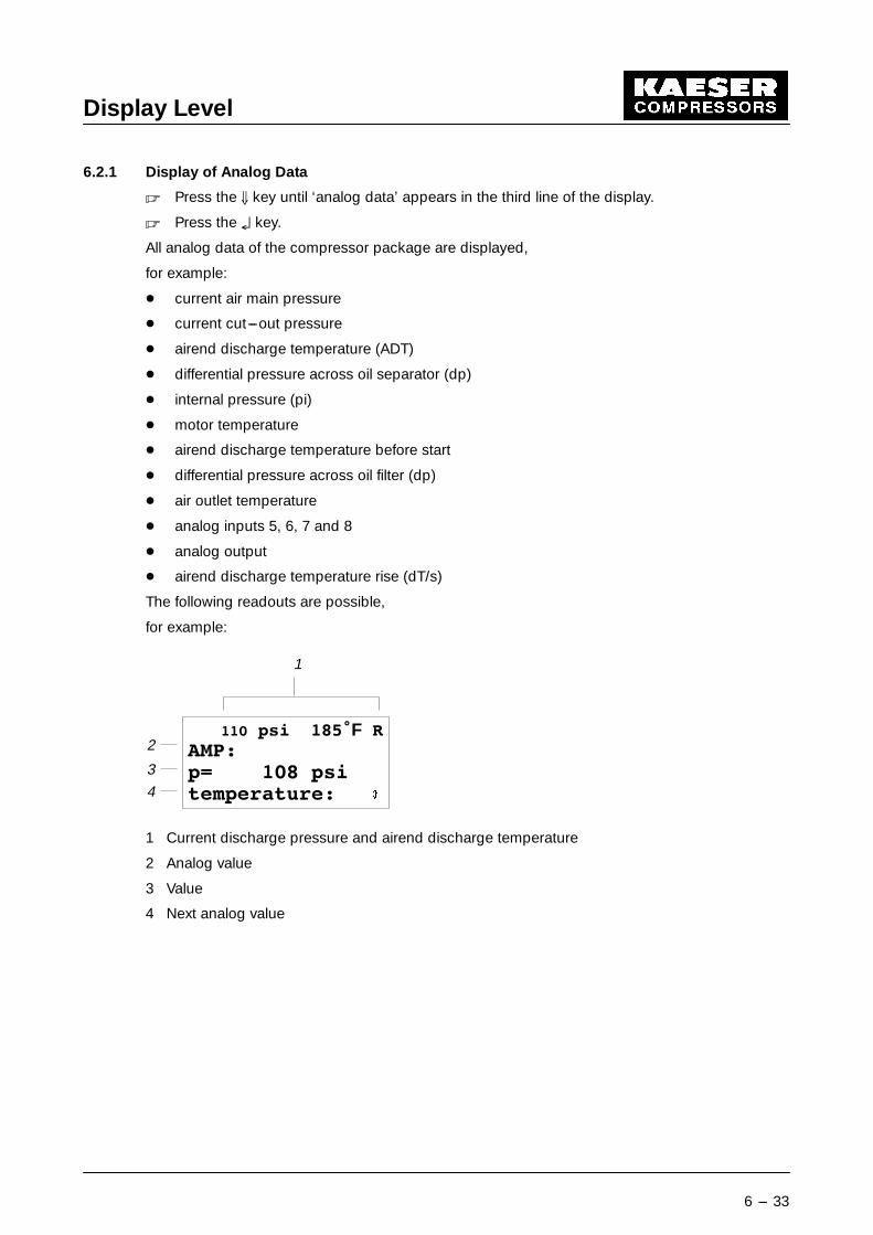
6.2.1 Display of Analog Data
� Press the 9 key until ‘analog data’ appears in the third line of the display.
� Press the § key.
All analog data of the compressor package are displayed,
for example:
- current air main pressure
- current cut---out pressure
- airend discharge temperature (ADT)
- differential pressure across oil separator (dp)
- internal pressure (pi)
- motor temperature
- airend discharge temperature before start
- differential pressure across oil filter (dp)
- air outlet temperature
- analog inputs 5, 6, 7 and 8
- analog output
- airend discharge temperature rise (dT/s)
The following readouts are possible,
for example:
1
2
3
4 F
��� SVL ����F 5$03�S ��� SVLWHPSHUDWXUH�
1 Current discharge pressure and airend discharge temperature
2 Analog value
3 Value
4 Next analog value

Display Level
6 --- 34
6.3 Hour Counter
§
Hour counter
--- Total hours--- Load hours--- Total utilization--- Number of motor starts--- Motor hours--- Airend hours--- Sigma hours--- Valve operations--- Regulating hours
§
HVF

Display Level
6 --- 35
6.3.1 Display of Hour Counter
� Press the 9 key until ‘hour counter’ appears in the third line of the display.
� Press the § key.
All hours run are displayed, such as
- total hours
- load hours
- total utilization
- number of motor starts
- motor hours
- airend hours
- Sigma hours
- load valve ON
- regulator hours
The following readouts are possible,
for example:
1
2
F
110 SVL ����F 5WRWDO KRXUV�
������ KORDG KRXUV�
2
34
1 Current discharge pressure and airend discharge temperature
2 Counter
3 Count value
4 Next counter

Display Level
6 --- 36
6.4 Service Hours
§
Service hours
--- Oil filter--- Oil separator--- Air filter--- Oil filling--- V---belts--- V---belt tension--- Motor bearings--- Electrical components
§
HVF

Display Level
6 --- 37
6.4.1 Display of Service Hours
� Press the 9 key until ‘service hours’ appears in the third line of the display.
� Press the § key.
All service hours until next service are displayed,
for example:
- oil filter
- oil separator
- air filter
- oil filling
- V---belts
- V---belt tension
- motor bearings
- electrical components (E---comp.:)
The following readouts are possible,
for example:
��� SVL ����F 5RLO ILOWHU�����K ����KRLO VHSDUDWRU�
1
2
45 F
3
1 Current discharge pressure and airend discharge temperature
2 Service hour counter
3 Remaining time to next service
4 Service interval
5 Next service hour counter

Display Level
6 --- 38
6.4.2 Resetting the service hour counter (maintenance interval counter)
When the corresponding maintenance has been carried out, reset the re-maining time (3) to the prescribed service interval (4).
The remaining times of the individual service hour counters can be reset individually.
� Press the 9 key until the required service hour counter (e.g. oil filter) appears in the third lineof the display,
for example:
F
��� SVL ����F 5
RLO ILOWHU�����K ��K
§
� Press the § key.
F
��� SVL ����F 5RLO ILOWHU�
UHVHW� QRLO ILOWHU�
§
� Activate submenu reset n for the corresponding service by pressing the § key.
� set reset y with the D key.
� Press the § key.
Reset the remaining time to the prescribed value.
� Exit the submenu with the ‘esc’ key.
Initial warning intervals can be changed in the above submenu.
Attention!

Display Level
6 --- 39

Display and Setup Level
7 --- 40
7 Display and Setup Level
In the display and setup level the panel test, timer configuration, PG functions, interfaces and his-tory (event information memory) are displayed and their settings can be changed.
7.1 Panel Test
§
Panel test
HVF
--- Lamps test
HVF

Display and Setup Level
7 --- 41
7.1.1 Display and setup of panel test
� Press the D until ‘panel test’ appears in the third line of the display.
� Press the § key.
The following display appears:
��� SVL ����F 5ODPSV WHVW�WHVW Q
1
2
3 §
F
1 Current discharge pressure and airend discharge temperature
2 Test to be carried out
3 Activation of test
7.1.1.1 Lamps test
� Press the § key.
� Configuration can be changed from ‘test n’ to ‘test y’ by pressing the D key.
� Press the § key.
@ All LEDs on the control panel should flash.
The display jumps back to ‘test n’ automatically after 10 seconds.
Display and Setup Level
7 --- 42
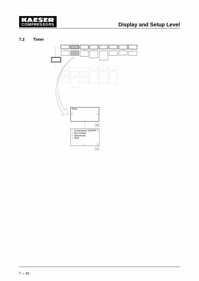
7.2 Timer
Timer
§
HVF
--- Compressor ON/OFF--- Dry contact--- Sequencer--- Print
§
HVF

Display and Setup Level
7 --- 43
7.2.1 Display and setup of the timer
� Press the D key until ‘timer’ appears in the third line of the display.
� Press the § key.
All settings affecting the timer can be displayed and changed.
Example:
- Compressor ON/OFF
- Dry contact
- Sequencer
- Printer
The following readouts are possible,
for example:
��� SVL ����F 5FRPS� 21�2))�GU\ FRQWDFWVHTXHQFHU
1
2 §
1 Current discharge pressure andairend discharge temperature
2 Various timer channelsF
� Scroll the menus up or down with the D9 keys.
� Scroll the timer channel to be changed into the third line and activate with the § key.
For example ‘compressor ON/OFF’ (timer channel for the compressor package):
��� SVL ����F 521�2)) GD\21�2)) ZHHN21�2)) \HDU
1
§
1 Current discharge pressure andairend discharge temperature
2 Daily schedule3 Weekly schedule4 Yearly scheduleF
32
4
� Scroll the menus up or down with the D9 keys.
� Scroll the schedule to be changed into the third line and activate with the § key.
For example: compressor daily schedule (‘ON/OFF day’)
��� SVL ����F 521�2)) GD\ �21� ��������2))� ��������
1
§
1 Current discharge pressure andairend discharge temperature
2 First time period3 Cut---in point of the compressor in
hours and minutes
4 Cut---out point of the compressor inhours and minutes
2
4
3
F
� The on and off times of the compressor can be changed by pressing the § key.
Display and Setup Level
7 --- 44
7.2.2 General description of the timer
The timer has four channels that are allocated fixed tasks:
- Channel 1 (compressor ON/OFF) switches the compressor package on and off.
- Channel 2 (dry contact) can be parameterized to an output A0.3.....A0.4 and is available forany external task.
- Channel 3 (sequencer) controls the sequencer. The sequencer rotates two compressors thatare operated in pressure---cascade control between duty and standby within set timeperiods.
- Channel 4 (printout) controls a timed printout of service and alarm messages if the timedprintout option via the timer is selected in the ‘print’ menu.
Four time periods for each day, each week and each year can be programmed for each channel.
A yearly schedule (month, day of the month, hour, minute), a weekly schedule (weekday, hour,minute) and a daily schedule (hour, minute) is available to the user for the input of switchingpoints. The switching points in the yearly and weekly schedules are entered as periods (with startand end) and the switching points in the daily schedule are entered as points in time.
7.2.2.1 The yearly schedule
An interruption of the cyclic daily schedule may be required if, for example, a public holiday oc-curs on a working day, or if a different schedule is required during holiday periods. These periodscan be started and ended at any convenient date and time. If no further such period is scheduledto follow the end of the first period, the program returns to the weekly schedule. As it is not poss-ible to enter the year in the periods, they are not unique, but repeat every year if they are not de-leted. The following conditions must be fulfilled to enable a correctly scheduled sequence of pro-grammed periods:
- The periods entered must contain all information required (start date, start time, end date,end time, required operational state).
7.2.2.2 The weekly schedule
All periods that are repeated during a weekly cycle are entered in the weekly schedule. If theoverriding yearly schedule is not active, a current period in the weekly schedule can be activated.The following conditions must must be fulfilled:
- The periods entered must contain all information required (start weekday, start time, endweekday, end time, required operational state).
7.2.2.3 The daily schedule
If the overriding yearly or weekly schedule is not active, the daily schedule is effective. The pro-grammed operational state of a switching point remains active until it is overridden by the oper-ational state of a following switching point or the weekly/yearly schedule activates.
- Only the switching points must entered.
When the ‘timer’ key is pressed (3, see chapter 4.4) only the command fromthe timer in channel 1 (compressor ON/OFF) is used to control the com-pressor package. The timer function itself is not influenced, that is, the timerruns permanently in the background.
Attention!

Display and Setup Level
7 --- 45
Example:
It is intended to run a compressor from 05:30 to 12:00 and from 13:00 to 21:10 daily.It is shut down at weekends from 14:00 Fridays to 05:30 Mondays, during company holidaysfrom 11 July to 26 July, and over the New Year from 12:00 on December 24 to 05:30 on January1.
Menu: timer -- compressor ON/OFF -- ON/OFF day:
- ON/OFF day 1ON: 05:30:00OFF: 12:00::00
- ON/OFF day 2ON: 13:00:00OFF: 21:10::00
Enter ‘0’ for day 3 and day 4 switching points.
Menu: timer -- compressor ON/OFF -- ON/OFF week:
- ON/OFF week 11�: Friday1�: 14:00:00
1 : Sunday1 : 23:59:59
1: comp. OFF
- ON/OFF week 22�: Monday2�: 00:00:00
2 : Monday2 : 05:30:00
2: comp. OFF
Enter ‘0’ for week 3 and week 4 switching points.
Menu: timer -- compressor ON/OFF -- ON/OFF year:
- ON/OFF year 11�: 11.07.# #1�: 00:00:00
1 : 26.07.# #1 : 23:59:59
1: comp. OFF
- ON/OFF year 22�: 24.12.# #2�: 12:00:00
2 : 31.12.# #2 : 23:59:59
2: compr. OFF

Display and Setup Level
7 --- 46
- ON/OFF year 33�: 01.01.# #3�: 00:00:00
3 : 02.01.# #3 : 05:30:00
3: comp. OFF
Enter ‘0’ for year 4.
‘> ’ is the start of the period‘< ’ is the end of the period‘# ’ without meaning
Note

Display and Setup Level
7 --- 47

Display and Setup Level
7 --- 48
7.3 Configuration
Configuration
§
HVF
§
--- Load/save data--- General--- Password--- Pressure settings--- Type of press. control--- Timing values--- Drive motor temp.--- Function selection

Display and Setup Level
7 --- 49
7.3.1 Display and setup of configuration
� Press the D key until ‘configuration’ appears in the third line of the display.
� Press the § key.
All settings affecting configuration can be displayed and changed,
for example:
- load/save data (from level 6) - Pressure control (p control)
- General - Timing values (from level 6)
- Password - Motor temperature
- Pressure settings - Function selection
The following readouts are possible,
for example:
��� SVL ����F 5ORDG�VDYH GDWDJHQHUDOSDVVZRUG
1
2 §1 Current discharge pressure and
airend discharge temperature2 Display of the various menusF
� Scroll the menus up or down with the D9 keys.
� Scroll the menu required into the third line and activate with the § key.
7.3.1.1 Load/save data submenu
Example:
��� SVL ����F 5VHWXS GDWDVDYH " QORDG " Q
1
3 §
F
1 Current discharge pressure andairend discharge temperature
2 Load/save setup data3 Save prompt4 Load prompt
2
4
� Scroll the menus up or down with the D9 keys.
� Scroll the function required to the third line of the display, activate with the § key and changethe ‘n’ setting to ‘y’.
7.3.1.2 General submenu
The following parameters are displayed and can be changed:
- Serial number (display only)
- Weekday
- Date

Display and Setup Level
7 --- 50
- Time
- Summer/Winter
- Language
- Date format (dd.mm.yy)
- Time format (hh:mm:ss)
- Unit of pressure (bar, hPa, MPa, psi, atü)
- Unit of temperature (EC, K, EF)
- Motor starts count: per day
- Inhibit keys
- Preselection keys: idle/remote/timer
7.3.1.3 Password submenu
Staggered access to the functions of the menu tree is possible with the help of a password.When the password menu is selected the cursor blinks over the place at the extreme left. All theavailable characters can now be scrolled with the UP/DOWN keys. The required character is se-lected with the § key and the cursor moves one place to the right. This procedure is repeateduntil all places are occupied by the password. The password is checked by pressing the § key, ifit is correct the corresponding level (e.g. level 5) is displayed. Subsequently the password menuis exited with the ‘esc’ key.
� Press the D key until ‘password’ appears in the third line of the display.
� Press the § key.
� Enter 5---character password with the help of the D9 keys.
� Press the § key.
7.3.1.4 Pressure settings submenu
- AMP (air system pressure)
This submenu is subdivided into:
- AMP p1
- AMP low
AMP p1
� Press the 9 key until the ‘AMP p1’ appears in the third line of the display and the press the §key.
The required air system pressure is displayed. The minimum pressure is computed by the con-troller.
AMP low
If the pressure falls below a set value a warning message is displayed but only if the ‘AMP low’function is activated.
To activate AMP low:
� Press the 9 key until the ‘AMP low’ appears in the second line of the display and ‘activate’appears in the third line.
� Press the § key.
� Change ‘n’ to ‘y’ with the 9 key and enter with § .
Display and Setup Level
7 --- 51
7.3.1.5 Pressure control submenu
The following types of control can be set:
- Dual control
- Quadro control
- Vario control
To activate/deactivate type of pressure control:
� Press the 9 key until the required type of pressure control appears in the third line of the dis-play.
� Press the § key.
� Change ‘n’ to ‘y’ with the D9 keys and enter with § .
7.3.1.6 Motor temperature submenu
This submenu contains the preset motor temperature above which a warning message is dis-played.
7.3.1.7 Function selection submenu
The following functions can be displayed or set:
- DO standard (standard digital output)
- remote select (display only)
- automatic restart
- pressure increase (display only)
- external load signal (display only)

Display and Setup Level
7 --- 52
7.4 PG Functions
PG functions
§
HVF
--- I/O status--- Set outputs
§

Display and Setup Level
7 --- 53
7.4.1 Display and setup of PG functions
� Press the D key until ‘PG functions’ (Programming functions) appears in the third line of thedisplay.
� Press the § key.
The current signal states of the digital inputs and outputs are displayed.
The following readouts are possible,
for example:
��� SVL ����F 5
,�2 VWDWXV
1
2 §
F
1 Current discharge pressure and airend discharge temperature
2 Activate status of digital inputs and outputs

Display and Setup Level
7 --- 54
7.5 Interfaces
§
HVF
Interfaces
--- RS 232--- RS485--- Profibus
§
Display and Setup Level
7 --- 55
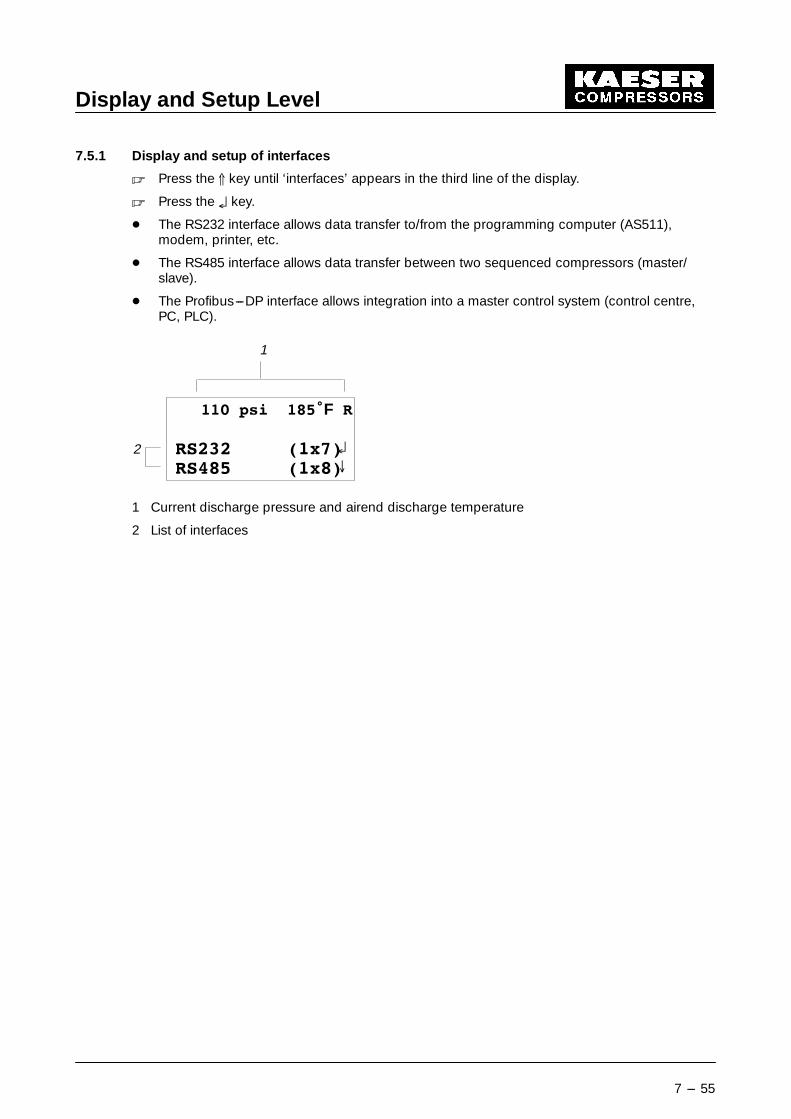
7.5.1 Display and setup of interfaces
� Press the D key until ‘interfaces’ appears in the third line of the display.
� Press the § key.
- The RS232 interface allows data transfer to/from the programming computer (AS511),modem, printer, etc.
- The RS485 interface allows data transfer between two sequenced compressors (master/slave).
- The Profibus---DP interface allows integration into a master control system (control centre,PC, PLC).
��� SVL ����F 5
56��� ��[��56��� ��[��
1
2 §
8
1 Current discharge pressure and airend discharge temperature
2 List of interfaces

Display and Setup Level
7 --- 56
7.6 History (Event Information Memory)
§
HVF
History (event info)
--- The last 100 eventsare stored anddisplayed

Display and Setup Level
7 --- 57
7.7 List of Abbreviations(n) compressor ”n” (where ”n” is
a number)(n+ 1) compressor ”n+ 1”(the next
number)A alarm or alarm messageact. activeAD airend dischargeADA air demand analysisadd. additionaladdr. addressADP airend discharge pressureADT airend discharge tempera-tureAI analog inputAM air systemAMC air system chargingAMP air system pressurean . analogAO analog outputauto. automaticavail. available, already existingB operational messagebitad. bit addressBP back pressurebytad. byte addressC alarm activated,
not yet acknowledgedc/o changeoverchar. charactercomp. compressorconfig. configurationconn. connectioncont. contactorCOP cut---off pressurecorr. correctionD data bitsDC Dual Controldbits. data bitsdel. delayDI digital inputdig. digitalDO digital outputDOL direct---onlineDoR direction of rotationdp delta p
(pressure differential or drop)dT delta T
(temperature differential ordrop)
dtrans. data transferE---comp. electrical componentsEM---STOP EMERGENCY STOPena. enableequip. equipmentext. external
F FAULTFC frequency converterfil. filterFr Fridayfunct. functionG fault rectified, reset alarmgrl. generalgrp. grouph hoursH or hys. hysteresishi highHT high tensionI input or currentID identityinh. inhibitinit. initialIS interlock switchL/i load/idlelo lowM motormaint. maintenancemax. maximummin minutemin. minimummodcontrol modulation controlMo Mondaymon. monitorMOPS motor overload protection
switchmsg. messagemxx maximum recorded or
highest reachedn no (negative answer to a
question)negn. negationno. numbernocont. no continuityNU not usedO outputoccu. occupancyOCO oil carry---overop. operationopl. operationaloptl. optionalOS oil separatorP parityp pressure, usually airmain
pressurepA pressure alarmPDT package discharge
temperatureparam. parameterpd periodPG programming function

Display and Setup Level
7 --- 58
pi internal pressure(in oil separator)
PL partial loadPLV partial load valveprot. protectionpsel. pre---selectpt low pressurePS power switchingPU power unitPW pressure warningPWH pressure warning hysteresisQ alarm acknowledgedQC quadro controlR RUNRAM random access memoryRB remote busRC remote contactred. reductionref. referenceregn. regulationRS rated speedS STOP or stop bits or sec. second(s)S/N serial number
Sa Saturdayseqr. sequencersh.cct short circuitsig. signalsp. speedst. startSu Sundaysw. switcht time valueT temperatureTA temperature alarmtdel. time delaytens. tensionTh Thursdayutil. utilizationUV unloading valveV rate of rise or fallVC Vario controlW warning, or maintenance
messageWe Wednesdayy yesY---delta star---delta (wye---delta)