service manual no-frost combi-refrigeratordiagramas.diagramasde.com/otros/erf-36_38_39_41.pdf ·...
TRANSCRIPT
SERVICE MANUAL NO-FROST COMBI-REFRIGERATOR
MODELS:
ENERGY UPGRADE
- ERF-36.A..EU- ERF-38.A..EU- ERF-39.A..EU- ERF-41.A..EU
ISOBUTANE (R-600)
- ERF-36.AR- ERF-38.AR- ERF-39.AR- ERF-41.AR
DAEWOO ELECTRONICS MANUFACTURING ESPAÑA S.A 2003
CONTENTS
- Precautions....................................................................... 3- Models equivalence remark.............................................. 4- Differences between ..4A and ..4..EU.............................. 4- Specifications.................................................................... 5- Wiring diagrams................................................................ 6- External drawing................................................................ 8- C/P difference betwenn ..4A and ..4A..EU....................... 8- Air flow diagram................................................................ 9- Refrigerant cycle diagram................................................ 10- Machine room view.......................................................... 11- Main pcb diagrams.......................................................... 12- Components disassembly pictures.................................. 16- Components specifications.............................................. 24- Explode drawings............................................. 26,30,34,38- Parts list............................................................ 28,32,36,40- Parts list of colour components........................................ 42- Pcb control functions........................................................ 44
TYPES OF THE APROVED SAFETY STANDARDS
Daewoo Electronics 2
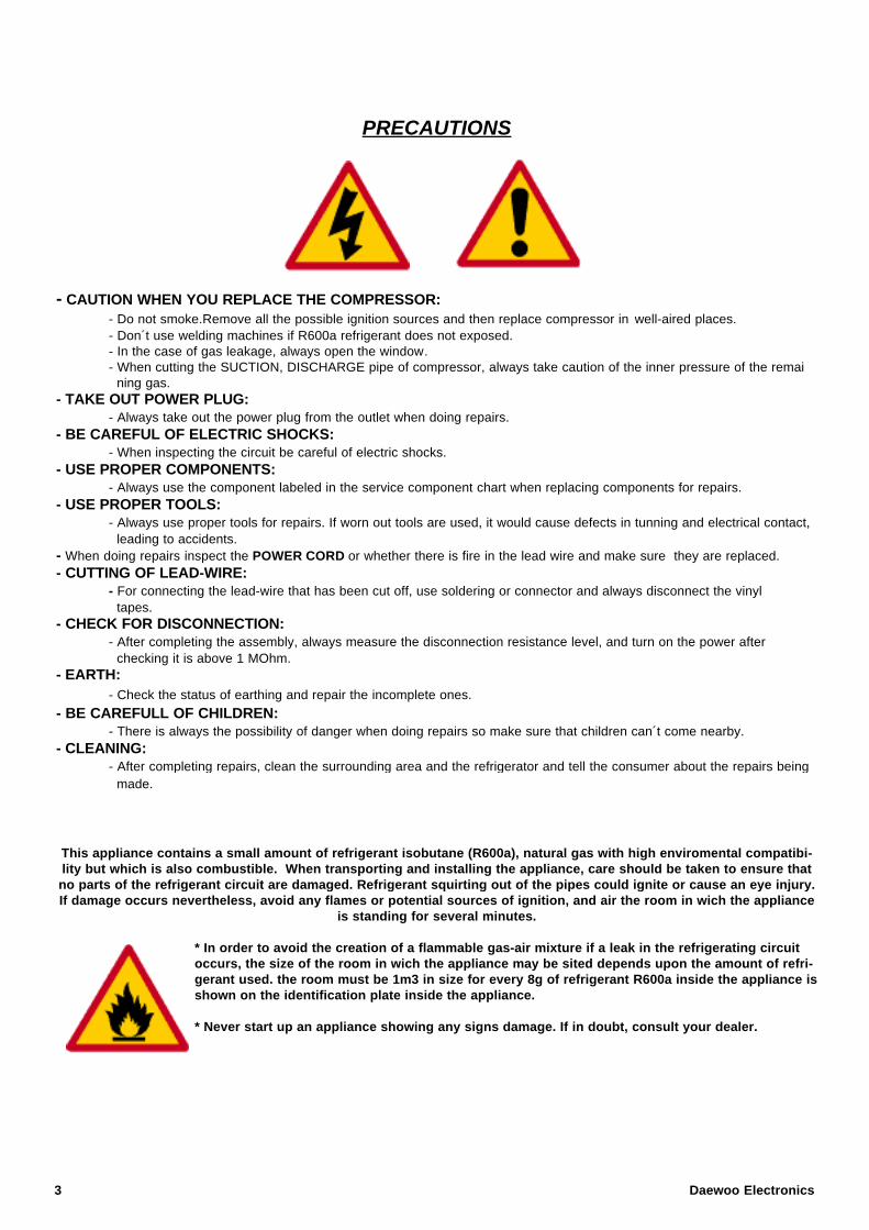
PRECAUTIONS
- CAUTION WHEN YOU REPLACE THE COMPRESSOR:- Do not smoke.Remove all the possible ignition sources and then replace compressor in well-aired places.- Don´t use welding machines if R600a refrigerant does not exposed.- In the case of gas leakage, always open the window.- When cutting the SUCTION, DISCHARGE pipe of compressor, always take caution of the inner pressure of the remai
ning gas.- TAKE OUT POWER PLUG:
- Always take out the power plug from the outlet when doing repairs.- BE CAREFUL OF ELECTRIC SHOCKS:
- When inspecting the circuit be careful of electric shocks.- USE PROPER COMPONENTS:
- Always use the component labeled in the service component chart when replacing components for repairs.- USE PROPER TOOLS:
- Always use proper tools for repairs. If worn out tools are used, it would cause defects in tunning and electrical contact, leading to accidents.
- When doing repairs inspect the POWER CORD or whether there is fire in the lead wire and make sure they are replaced.- CUTTING OF LEAD-WIRE:
- For connecting the lead-wire that has been cut off, use soldering or connector and always disconnect the vinyl tapes.
- CHECK FOR DISCONNECTION:- After completing the assembly, always measure the disconnection resistance level, and turn on the power after
checking it is above 1 MOhm.- EARTH:
- Check the status of earthing and repair the incomplete ones.
- BE CAREFULL OF CHILDREN:- There is always the possibility of danger when doing repairs so make sure that children can´t come nearby.
- CLEANING:- After completing repairs, clean the surrounding area and the refrigerator and tell the consumer about the repairs being
made.
This appliance contains a small amount of refrigerant isobutane (R600a), natural gas with high enviromental compatibi-lity but which is also combustible. When transporting and installing the appliance, care should be taken to ensure thatno parts of the refrigerant circuit are damaged. Refrigerant squirting out of the pipes could ignite or cause an eye injury.If damage occurs nevertheless, avoid any flames or potential sources of ignition, and air the room in wich the appliance
is standing for several minutes.
* In order to avoid the creation of a flammable gas-air mixture if a leak in the refrigerating circuitoccurs, the size of the room in wich the appliance may be sited depends upon the amount of refri-gerant used. the room must be 1m3 in size for every 8g of refrigerant R600a inside the appliance isshown on the identification plate inside the appliance.
* Never start up an appliance showing any signs damage. If in doubt, consult your dealer.
3 Daewoo Electronics
MODELS EQUIVALENCE REMARK
- Cosmetic differences, colour, ... relate to the model number. This manual refers to the standard models, but technical contents are similar for the rest of models. Standard models are:
ERF-364AR, ERF-384AR, ERF-394AR, ERF-414ARERF-367AR, ERF-387AR, ERF-397AR, ERF- 417AR
ERF-364A..EU, ERF-384A..EU, ERF-394A..EU, ERF-414A..EUERF-367A..EU, ERF-387A..EU, ERF-397A..EU, ERF- 417A..EU
DIFERENCES BETWEEN “ERF-..4A, ..7A” AND “ERF-..4..EU, ..7A..EU”
- These models are basically similar, but for improve the energy efficiency, some components have been changed:
- NEW PARTS FOR ERF-364A..EU, 384A..EU, 394A..EU, 414A..EU:
PCB MAIN AS: 30143B8060PCB FRONT AS: 30143B6160WINDOW C/PANEL L/L: 3015507220
- NEW PARTS FOR ERF-367A..EU, 387A..EU, 397A..EU, 417A..EU:
PCB MAIN AS: 30143B9060
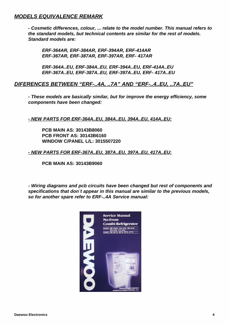
- Wiring diagrams and pcb circuits have been changed but rest of components and specifications that don´t appear in this manual are similar to the previous models, so for another spare refer to ERF-..4A Service manual:
Daewoo Electronics 4
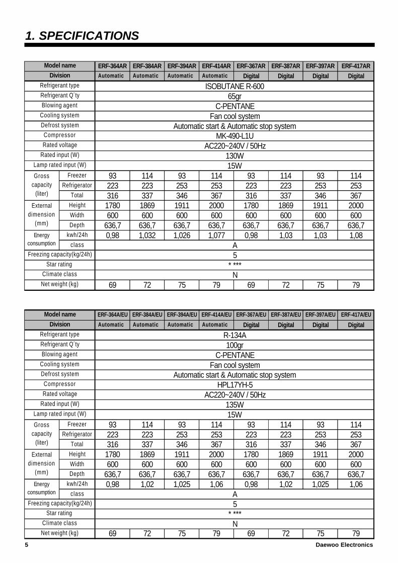
1. SPECIFICATIONS
ERF-364AR ERF-384AR ERF-394AR ERF-414AR ERF-367AR ERF-387AR ERF-397AR ERF-417ARAutomatic Automatic Automatic Automatic Digital Digital Digital Digital
Freezer 93 114 93 114 93 114 93 114Refrigerator 223 223 253 253 223 223 253 253
Total 316 337 346 367 316 337 346 367Height 1780 1869 1911 2000 1780 1869 1911 2000Width 600 600 600 600 600 600 600 600Depth 636,7 636,7 636,7 636,7 636,7 636,7 636,7 636,7
kwh/24h 0,98 1,032 1,026 1,077 0,98 1,03 1,03 1,08class
69 72 75 79 69 72 75 79
ERF-364A/EU ERF-384A/EU ERF-394A/EU ERF-414A/EU ERF-367A/EU ERF-387A/EU ERF-397A/EU ERF-417A/EU
Automatic Automatic Automatic Automatic Digital Digital Digital Digital
Freezer 93 114 93 114 93 114 93 114Refrigerator 223 223 253 253 223 223 253 253
Total 316 337 346 367 316 337 346 367Height 1780 1869 1911 2000 1780 1869 1911 2000Width 600 600 600 600 600 600 600 600Depth 636,7 636,7 636,7 636,7 636,7 636,7 636,7 636,7
kwh/24h 0,98 1,02 1,025 1,06 0,98 1,02 1,025 1,06class
69 72 75 79 69 72 75 79
Defrost system
Refrigerant type
Grosscapacity
(liter)
Compressor
Rated voltage
Lamp rated input (W)
Rated input (W)
Division
Model name
Cooling system
Blowing agent
Refrigerant Q´ty
Net weight (kg)
Freezing capacity(kg/24h)
Climate class
Star rating
Externaldimension
(mm)
Energyconsumption
Model name
5* ***
N
Grosscapacity
(liter)
Externaldimension
(mm)
HPL17YH-5Rated voltage AC220~240V / 50Hz
Rated input (W)
Compressor
Division
Refrigerant type
Blowing agent
Cooling system
Defrost system Automatic start & Automatic stop system
R-134A
C-PENTANE
ISOBUTANE R-600
C-PENTANEFan cool system
Automatic start & Automatic stop system
65gr
MK-490-L1UAC220~240V / 50Hz
15W
Energyconsumption A
100gr
130W
Refrigerant Q´ty
A
Fan cool system
Freezing capacity(kg/24h) 5
Net weight (kg)
135W
Star rating * ***Climate class N
Lamp rated input (W) 15W
5 Daewoo Electronics
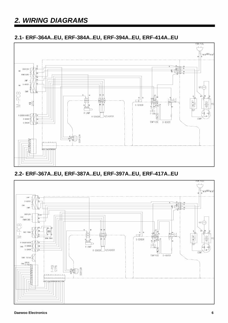
2. WIRING DIAGRAMS
2.1- ERF-364A..EU, ERF-384A..EU, ERF-394A..EU, ERF-414A..EU
2.2- ERF-367A..EU, ERF-387A..EU, ERF-397A..EU, ERF-417A..EU
Daewoo Electronics 6
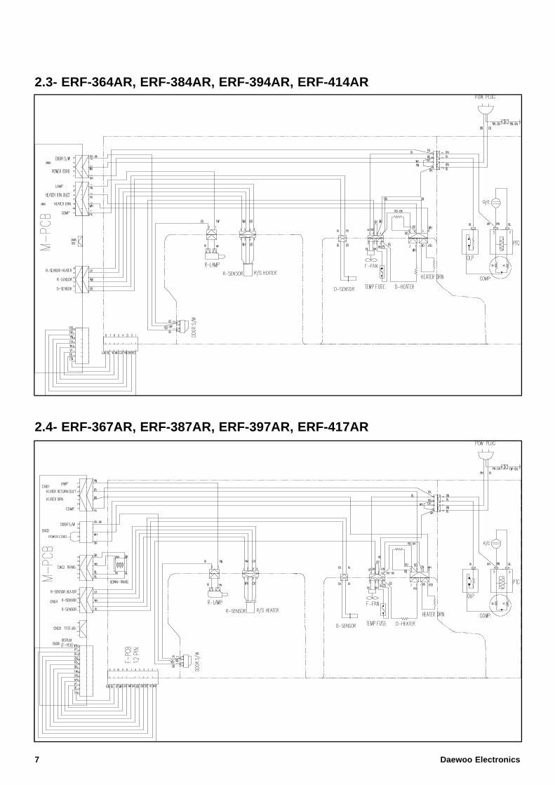
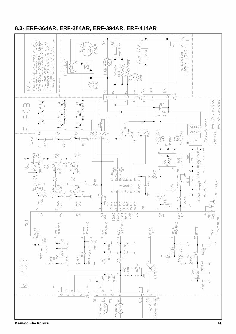
2.3- ERF-364AR, ERF-384AR, ERF-394AR, ERF-414AR
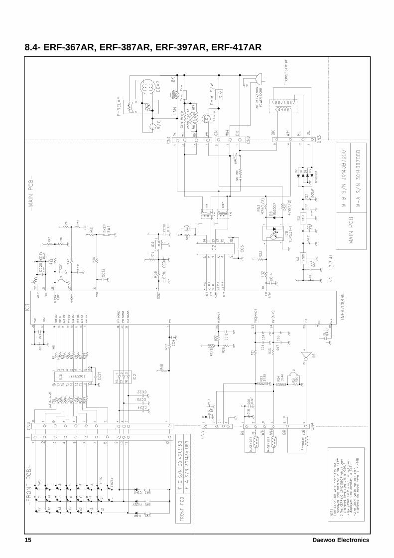
2.4- ERF-367AR, ERF-387AR, ERF-397AR, ERF-417AR
7 Daewoo Electronics
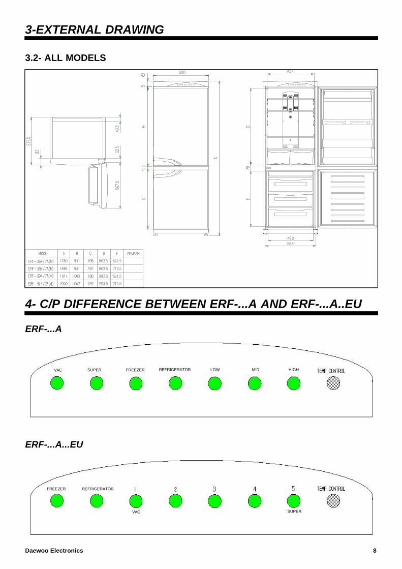
3-EXTERNAL DRAWING
3.2- ALL MODELS
4- C/P DIFFERENCE BETWEEN ERF-...A AND ERF-...A..EU
ERF-...A
ERF-...A...EU
VAC SUPER REFRIGERATORFREEZER HIGHMIDLOW
FREEZER REFRIGERATOR
VAC SUPER
Daewoo Electronics 8
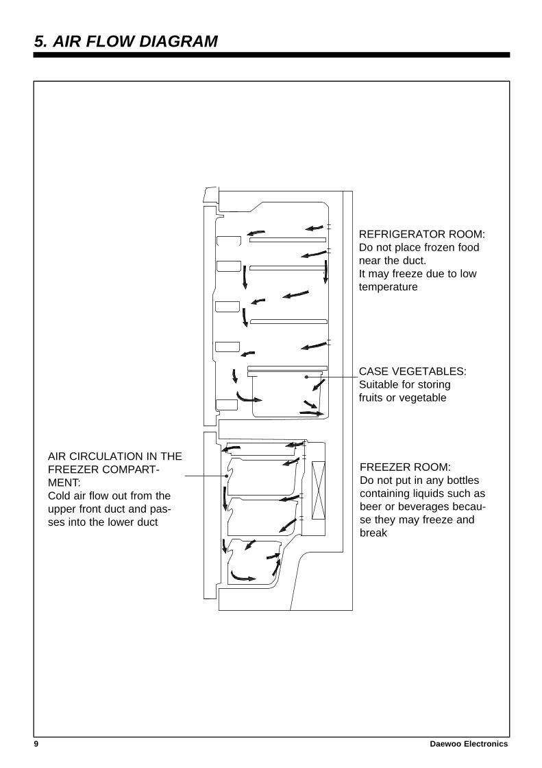
5. AIR FLOW DIAGRAM
FREEZER ROOM:Do not put in any bottlescontaining liquids such asbeer or beverages becau-se they may freeze andbreak
AIR CIRCULATION IN THEFREEZER COMPART-MENT:Cold air flow out from theupper front duct and pas-ses into the lower duct
CASE VEGETABLES:Suitable for storingfruits or vegetable
REFRIGERATOR ROOM:Do not place frozen foodnear the duct.It may freeze due to lowtemperature
9 Daewoo Electronics
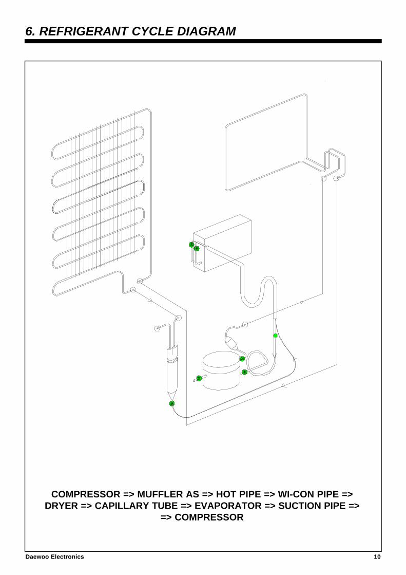
6. REFRIGERANT CYCLE DIAGRAM
COMPRESSOR => MUFFLER AS => HOT PIPE => WI-CON PIPE =>DRYER => CAPILLARY TUBE => EVAPORATOR => SUCTION PIPE =>
=> COMPRESSOR
Daewoo Electronics 10
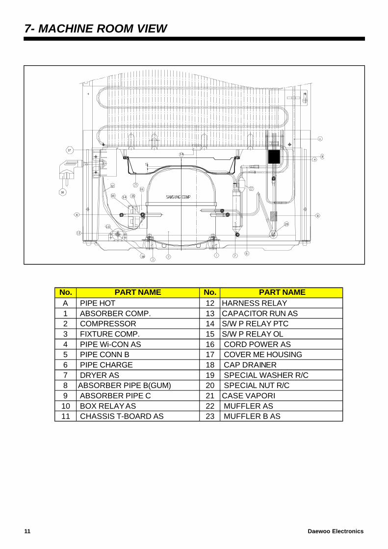
7- MACHINE ROOM VIEW
SPECIAL NUT R/CCASE VAPORI MUFFLER AS MUFFLER B AS
2223
21
S/W P RELAY PTCS/W P RELAY OL CORD POWER AS COVER ME HOUSING17
ABSORBER PIPE B(GUM)
CAP DRAINER SPECIAL WASHER R/C
181920
CHASSIS T-BOARD AS
FIXTURE COMP. PIPE Wi-CON AS
PIPE CHARGE
No. PART NAME
ABSORBER PIPE C BOX RELAY AS
2 COMPRESSOR3
10
4
No.
PIPE CONN B
DRYER AS
HARNESS RELAYPART NAME
ABSORBER COMP. 13 CAPACITOR RUN AS
1516
14
A PIPE HOT 121
11
5
7
9
6
8
10
5
6
7
8
9
1112
13
1514
16
1718
19
A
23
11 Daewoo Electronics
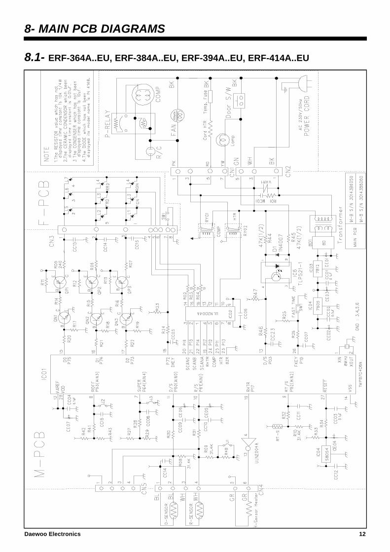
8- MAIN PCB DIAGRAMS
8.1- ERF-364A..EU, ERF-384A..EU, ERF-394A..EU, ERF-414A..EU
Daewoo Electronics 12

8.2- ERF-367A..EU, ERF-387A..EU, ERF-397A..EU, ERF-417A..EU
13 Daewoo Electronics
8.3- ERF-364AR, ERF-384AR, ERF-394AR, ERF-414AR
Daewoo Electronics 14
8.4- ERF-367AR, ERF-387AR, ERF-397AR, ERF-417AR
15 Daewoo Electronics

9. COMPONENTS DISASSEMBLY PICTURES
1-CONTROL PANEL
1.1- Take out control panel by pulling it up and inserting a minus driver like picture shows, and move itleft-right.
1.2- Disconnect F-Pcb harness andswitch lamp.
1.3- Remove 2 upper screws to takeout base control panel.
Daewoo Electronics 16
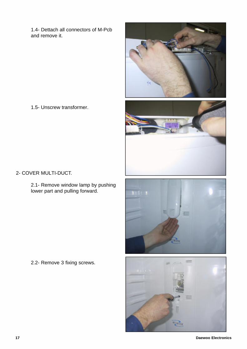
1.4- Dettach all connectors of M-Pcband remove it.
1.5- Unscrew transformer.
2- COVER MULTI-DUCT.
2.1- Remove window lamp by pushinglower part and pulling forward.
2.2- Remove 3 fixing screws.
17 Daewoo Electronics
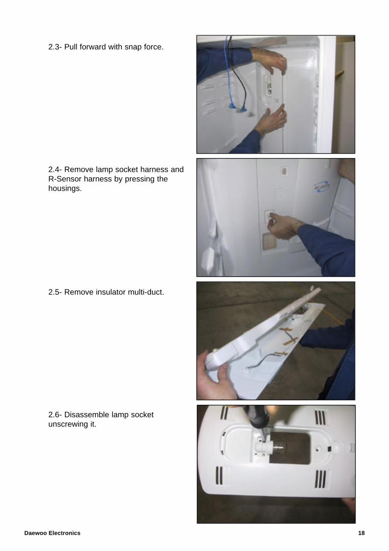
2.3- Pull forward with snap force.
2.4- Remove lamp socket harness andR-Sensor harness by pressing thehousings.
2.5- Remove insulator multi-duct.
2.6- Disassemble lamp socketunscrewing it.
Daewoo Electronics 18
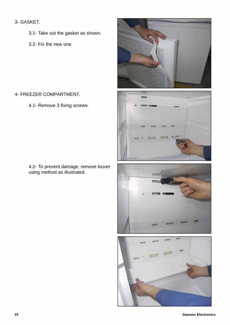
3- GASKET.
3.1- Take out the gasket as shown.
3.2- Fix the new one.
4- FREEZER COMPARTMENT.
4.1- Remove 3 fixing screws.
4.2- To prevent damage, remove louver using method as illustrated.
19 Daewoo Electronics
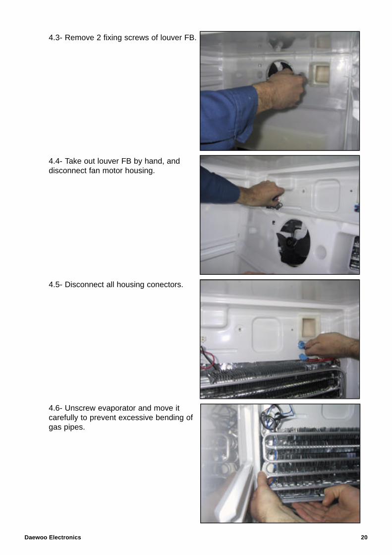
4.3- Remove 2 fixing screws of louver FB.
4.4- Take out louver FB by hand, anddisconnect fan motor housing.
4.5- Disconnect all housing conectors.
4.6- Unscrew evaporator and move it carefully to prevent excessive bending of gas pipes.
Daewoo Electronics 20

4.7- To replace fuse temp.
- Take out fuse temp from the leftpart of evaporator and cut blackand grey wires.
- Join cut wires with the new fusewires.
- Cover joint point with insulatedtape (best way is heat shrink tube).
4.8- To replace D-Sensor.
- Take out D-Sensor from the lowerpart of evaporator cutting cable tie.
21 Daewoo Electronics
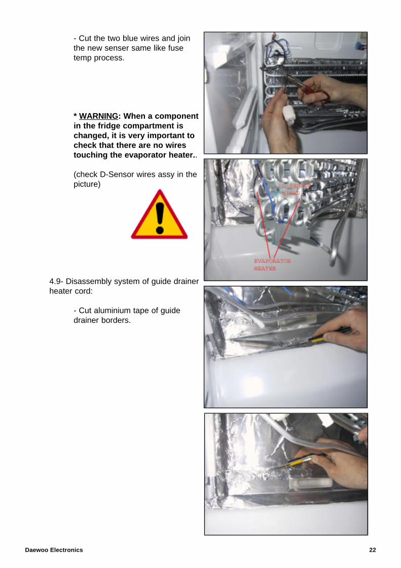
- Cut the two blue wires and join the new senser same like fuse temp process.
* WARNING: When a component in the fridge compartment is changed, it is very important to check that there are no wires touching the evaporator heater..
(check D-Sensor wires assy in thepicture)
4.9- Disassembly system of guide drainer heater cord:
- Cut aluminium tape of guidedrainer borders.
Daewoo Electronics 22
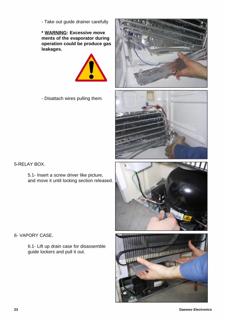
- Take out guide drainer carefully
* WARNING: Excessive movements of the evaporator during operation could be produce gas leakages.
- Disattach wires pulling them.
5-RELAY BOX.
5.1- Insert a screw driver like picture, and move it until locking section released.
6- VAPORY CASE.
6.1- Lift up drain case for disassemble guide lockers and pull it out.
23 Daewoo Electronics
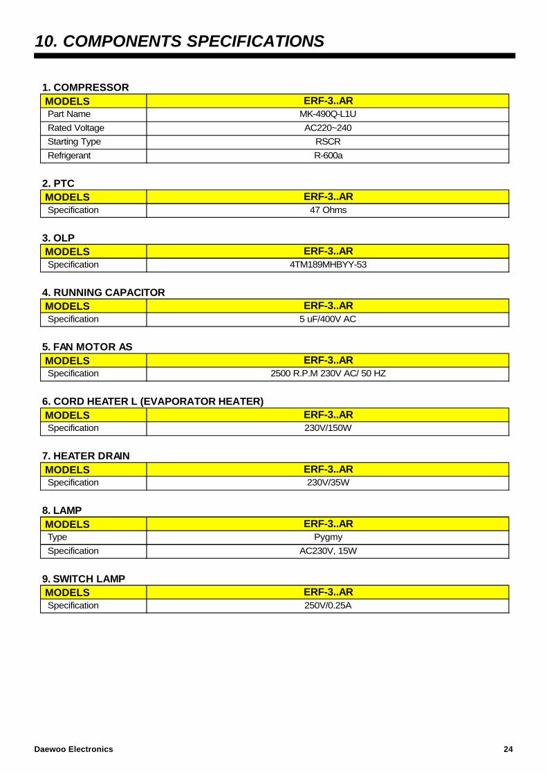
10. COMPONENTS SPECIFICATIONS
1. COMPRESSOR
2. PTC
3. OLP
4. RUNNING CAPACITOR
5. FAN MOTOR AS
6. CORD HEATER L (EVAPORATOR HEATER)
7. HEATER DRAIN
8. LAMP
9. SWITCH LAMP
RSCR
R-600a
2500 R.P.M 230V AC/ 50 HZ
ERF-3..AR
ERF-3..AR
MODELS Specification 47 Ohms
ERF-3..AR
5 uF/400V AC SpecificationERF-3..AR
Specification 4TM189MHBYY-53
Type Pygmy
AC230V, 15W
Specification 250V/0.25A
MODELS Specification
MODELS
MODELS
MODELS
MODELS
MODELS
Part Name
Rated Voltage
MODELSMK-490Q-L1U
AC220~240
ERF-3..AR
Specification
Starting Type
Refrigerant
MODELS
Specification
Specification
ERF-3..AR
ERF-3..AR
ERF-3..AR
ERF-3..AR
230V/35W
230V/150W
Daewoo Electronics 24
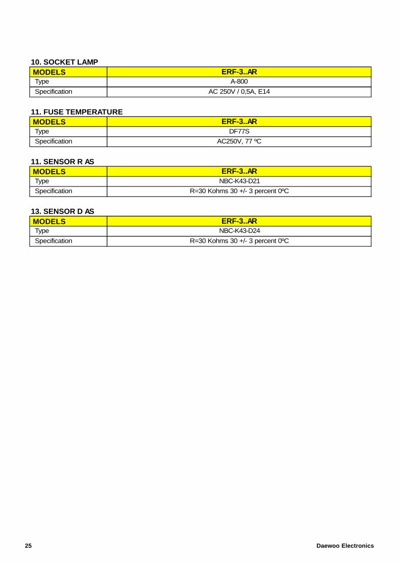
10. SOCKET LAMP
11. FUSE TEMPERATURE
11. SENSOR R AS
13. SENSOR D AS
MODELS
Type
Type
R=30 Kohms 30 +/- 3 percent 0ºC
AC250V, 77 ºC
AC 250V / 0,5A, E14
DF77S
Specification
A-800
MODELS
MODELS
Specification
Type
Specification
Type
Specification
MODELSNBC-K43-D24
R=30 Kohms 30 +/- 3 percent 0ºC
ERF-3..AR
ERF-3..AR
ERF-3..AR
ERF-3..AR
NBC-K43-D21
25 Daewoo Electronics
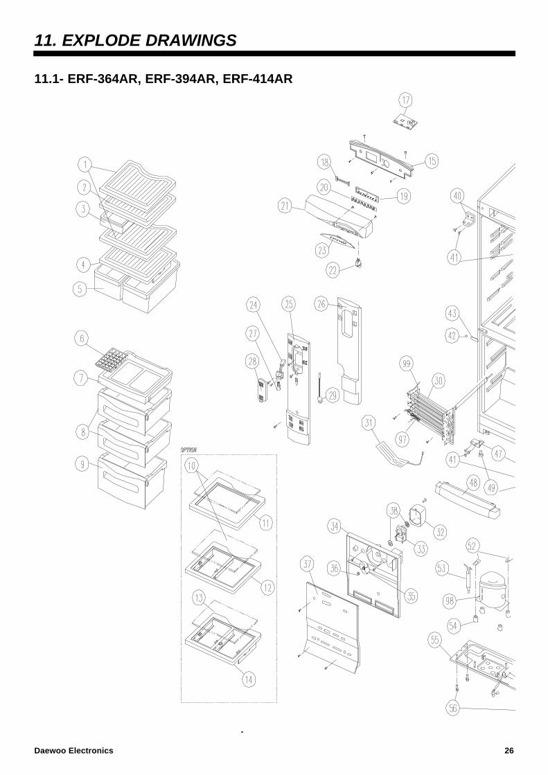
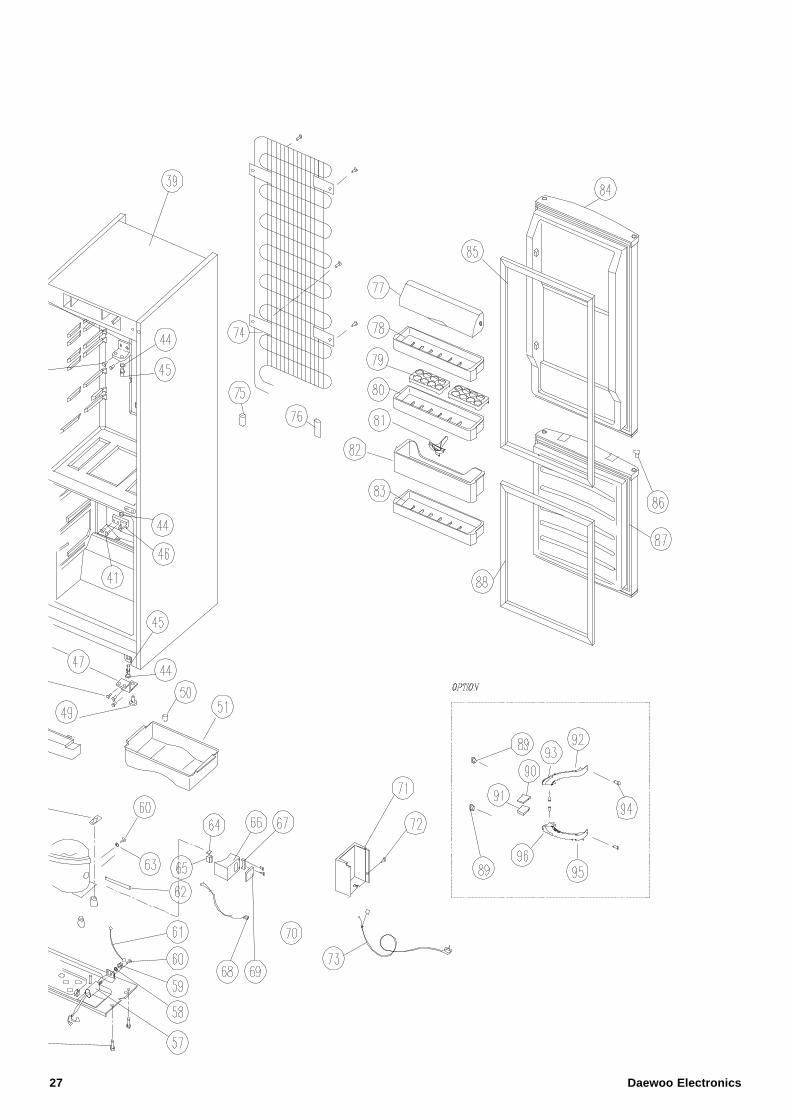
11. EXPLODE DRAWINGS
11.1- ERF-364AR, ERF-394AR, ERF-414AR
Daewoo Electronics 26
27 Daewoo Electronics
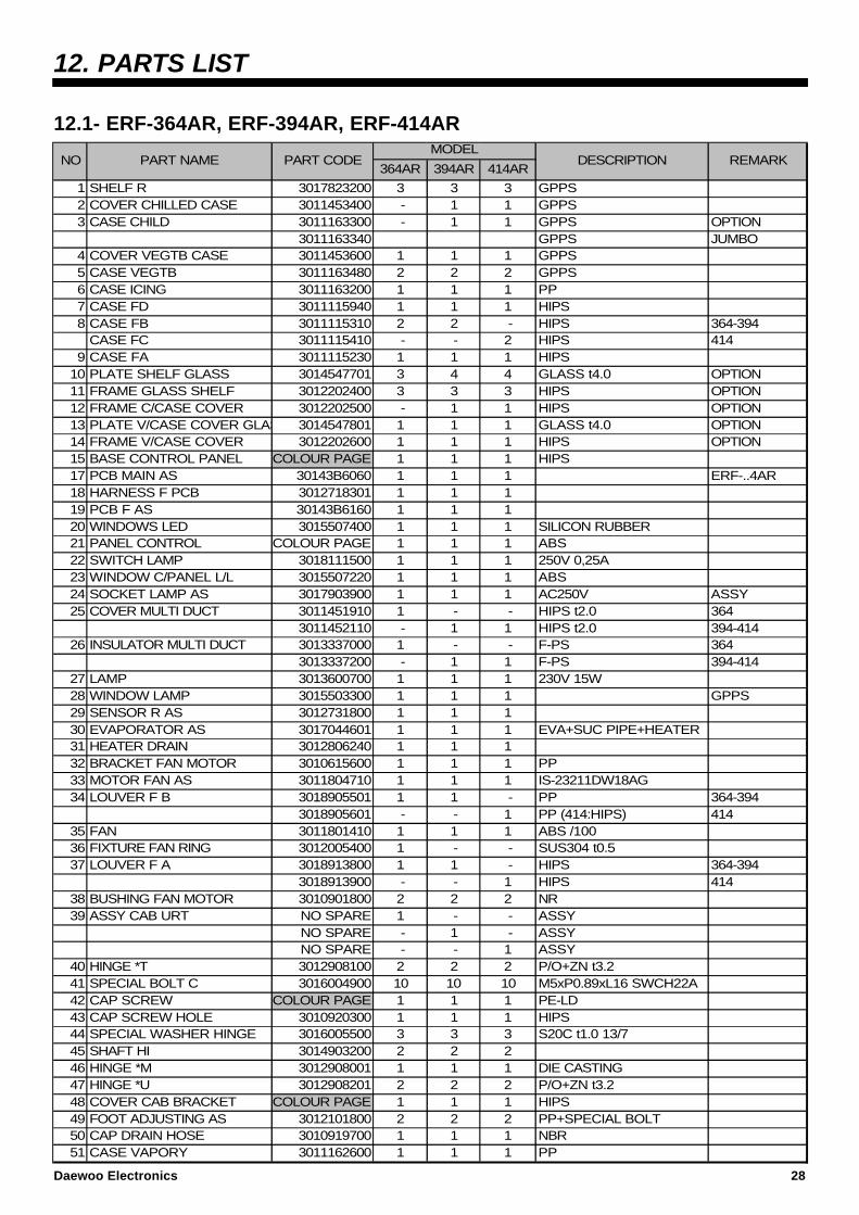
12. PARTS LIST
12.1- ERF-364AR, ERF-394AR, ERF-414AR
364AR 394AR 414AR
1 SHELF R 3017823200 3 3 3 GPPS2 COVER CHILLED CASE 3011453400 - 1 1 GPPS3 CASE CHILD 3011163300 - 1 1 GPPS OPTION
3011163340 GPPS JUMBO4 COVER VEGTB CASE 3011453600 1 1 1 GPPS5 CASE VEGTB 3011163480 2 2 2 GPPS6 CASE ICING 3011163200 1 1 1 PP7 CASE FD 3011115940 1 1 1 HIPS8 CASE FB 3011115310 2 2 - HIPS 364-394
CASE FC 3011115410 - - 2 HIPS 4149 CASE FA 3011115230 1 1 1 HIPS
10 PLATE SHELF GLASS 3014547701 3 4 4 GLASS t4.0 OPTION11 FRAME GLASS SHELF 3012202400 3 3 3 HIPS OPTION12 FRAME C/CASE COVER 3012202500 - 1 1 HIPS OPTION13 PLATE V/CASE COVER GLASS 3014547801 1 1 1 GLASS t4.0 OPTION14 FRAME V/CASE COVER 3012202600 1 1 1 HIPS OPTION15 BASE CONTROL PANEL COLOUR PAGE 1 1 1 HIPS17 PCB MAIN AS 30143B6060 1 1 1 ERF-..4AR18 HARNESS F PCB 3012718301 1 1 119 PCB F AS 30143B6160 1 1 120 WINDOWS LED 3015507400 1 1 1 SILICON RUBBER21 PANEL CONTROL COLOUR PAGE 1 1 1 ABS22 SWITCH LAMP 3018111500 1 1 1 250V 0,25A23 WINDOW C/PANEL L/L 3015507220 1 1 1 ABS24 SOCKET LAMP AS 3017903900 1 1 1 AC250V ASSY25 COVER MULTI DUCT 3011451910 1 - - HIPS t2.0 364
3011452110 - 1 1 HIPS t2.0 394-41426 INSULATOR MULTI DUCT 3013337000 1 - - F-PS 364
3013337200 - 1 1 F-PS 394-41427 LAMP 3013600700 1 1 1 230V 15W28 WINDOW LAMP 3015503300 1 1 1 GPPS29 SENSOR R AS 3012731800 1 1 130 EVAPORATOR AS 3017044601 1 1 1 EVA+SUC PIPE+HEATER31 HEATER DRAIN 3012806240 1 1 132 BRACKET FAN MOTOR 3010615600 1 1 1 PP33 MOTOR FAN AS 3011804710 1 1 1 IS-23211DW18AG34 LOUVER F B 3018905501 1 1 - PP 364-394
3018905601 - - 1 PP (414:HIPS) 41435 FAN 3011801410 1 1 1 ABS /10036 FIXTURE FAN RING 3012005400 1 - - SUS304 t0.537 LOUVER F A 3018913800 1 1 - HIPS 364-394
3018913900 - - 1 HIPS 41438 BUSHING FAN MOTOR 3010901800 2 2 2 NR39 ASSY CAB URT NO SPARE 1 - - ASSY
NO SPARE - 1 - ASSY NO SPARE - - 1 ASSY
40 HINGE *T 3012908100 2 2 2 P/O+ZN t3.241 SPECIAL BOLT C 3016004900 10 10 10 M5xP0.89xL16 SWCH22A42 CAP SCREW COLOUR PAGE 1 1 1 PE-LD43 CAP SCREW HOLE 3010920300 1 1 1 HIPS44 SPECIAL WASHER HINGE 3016005500 3 3 3 S20C t1.0 13/745 SHAFT HI 3014903200 2 2 246 HINGE *M 3012908001 1 1 1 DIE CASTING47 HINGE *U 3012908201 2 2 2 P/O+ZN t3.248 COVER CAB BRACKET COLOUR PAGE 1 1 1 HIPS49 FOOT ADJUSTING AS 3012101800 2 2 2 PP+SPECIAL BOLT50 CAP DRAIN HOSE 3010919700 1 1 1 NBR51 CASE VAPORY 3011162600 1 1 1 PP
DESCRIPTION REMARKMODEL
NO PART NAME PART CODE
Daewoo Electronics 28
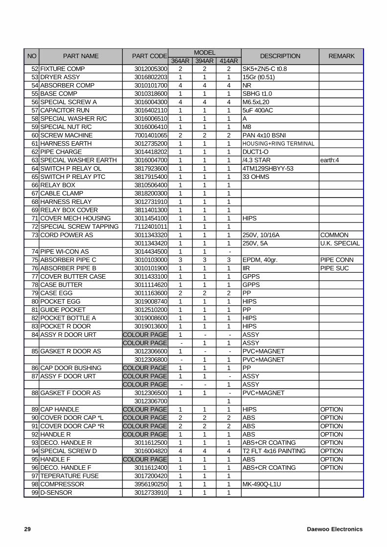
364AR 394AR 414AR52 FIXTURE COMP 3012005300 2 2 2 SK5+ZN5-C t0.853 DRYER ASSY 3016802203 1 1 1 15Gr (t0.51)54 ABSORBER COMP 3010101700 4 4 4 NR55 BASE COMP 3010318600 1 1 1 SBHG t1.056 SPECIAL SCREW A 3016004300 4 4 4 M6.5xL2057 CAPACITOR RUN 3016402110 1 1 1 5uF 400AC58 SPECIAL WASHER R/C 3016006510 1 1 1 A59 SPECIAL NUT R/C 3016006410 1 1 1 M860 SCREW MACHINE 7001401065 2 2 2 PAN 4x10 BSNI61 HARNESS EARTH 3012735200 1 1 1 HOUSING+RING TERMINAL62 PIPE CHARGE 3014418202 1 1 1 DUCT1-O63 SPECIAL WASHER EARTH 3016004700 1 1 1 /4.3 STAR earth:464 SWITCH P RELAY OL 3817923600 1 1 1 4TM129SHBYY-5365 SWITCH P RELAY PTC 3817915400 1 1 1 33 OHMS66 RELAY BOX 3810506400 1 1 167 CABLE CLAMP 3818200300 1 1 168 HARNESS RELAY 3012731910 1 1 169 RELAY BOX COVER 3811401300 1 1 171 COVER MECH HOUSING 3011454100 1 1 1 HIPS72 SPECIAL SCREW TAPPING 7112401011 1 1 173 CORD POWER AS 3011343320 1 1 1 250V, 10/16A COMMON
3011343420 1 1 1 250V, 5A U.K. SPECIAL74 PIPE WI-CON AS 3014434500 1 1 -75 ABSORBER PIPE C 3010103000 3 3 3 EPDM, 40gr. PIPE CONN76 ABSORBER PIPE B 3010101900 1 1 1 IIR PIPE SUC77 COVER BUTTER CASE 3011433100 1 1 1 GPPS78 CASE BUTTER 3011114620 1 1 1 GPPS79 CASE EGG 3011163600 2 2 2 PP80 POCKET EGG 3019008740 1 1 1 HIPS81 GUIDE POCKET 3012510200 1 1 1 PP82 POCKET BOTTLE A 3019008600 1 1 1 HIPS83 POCKET R DOOR 3019013600 1 1 1 HIPS84 ASSY R DOOR URT COLOUR PAGE 1 - - ASSY
COLOUR PAGE - 1 1 ASSY85 GASKET R DOOR AS 3012306600 1 - - PVC+MAGNET
3012306800 - 1 1 PVC+MAGNET86 CAP DOOR BUSHING COLOUR PAGE 1 1 1 PP87 ASSY F DOOR URT COLOUR PAGE 1 1 - ASSY
COLOUR PAGE - - 1 ASSY88 GASKET F DOOR AS 3012306500 1 1 - PVC+MAGNET
3012306700 189 CAP HANDLE COLOUR PAGE 1 1 1 HIPS OPTION90 COVER DOOR CAP *L COLOUR PAGE 2 2 2 ABS OPTION91 COVER DOOR CAP *R COLOUR PAGE 2 2 2 ABS OPTION92 HANDLE R COLOUR PAGE 1 1 1 ABS OPTION93 DECO. HANDLE R 3011612500 1 1 1 ABS+CR COATING OPTION94 SPECIAL SCREW D 3016004820 4 4 4 T2 FLT 4x16 PAINTING OPTION95 HANDLE F COLOUR PAGE 1 1 1 ABS OPTION96 DECO. HANDLE F 3011612400 1 1 1 ABS+CR COATING OPTION97 TEPERATURE FUSE 3017200420 1 1 198 COMPRESSOR 3956190250 1 1 1 MK-490Q-L1U99 D-SENSOR 3012733910 1 1 1
MODELNO PART NAME PART CODE DESCRIPTION REMARK
29 Daewoo Electronics
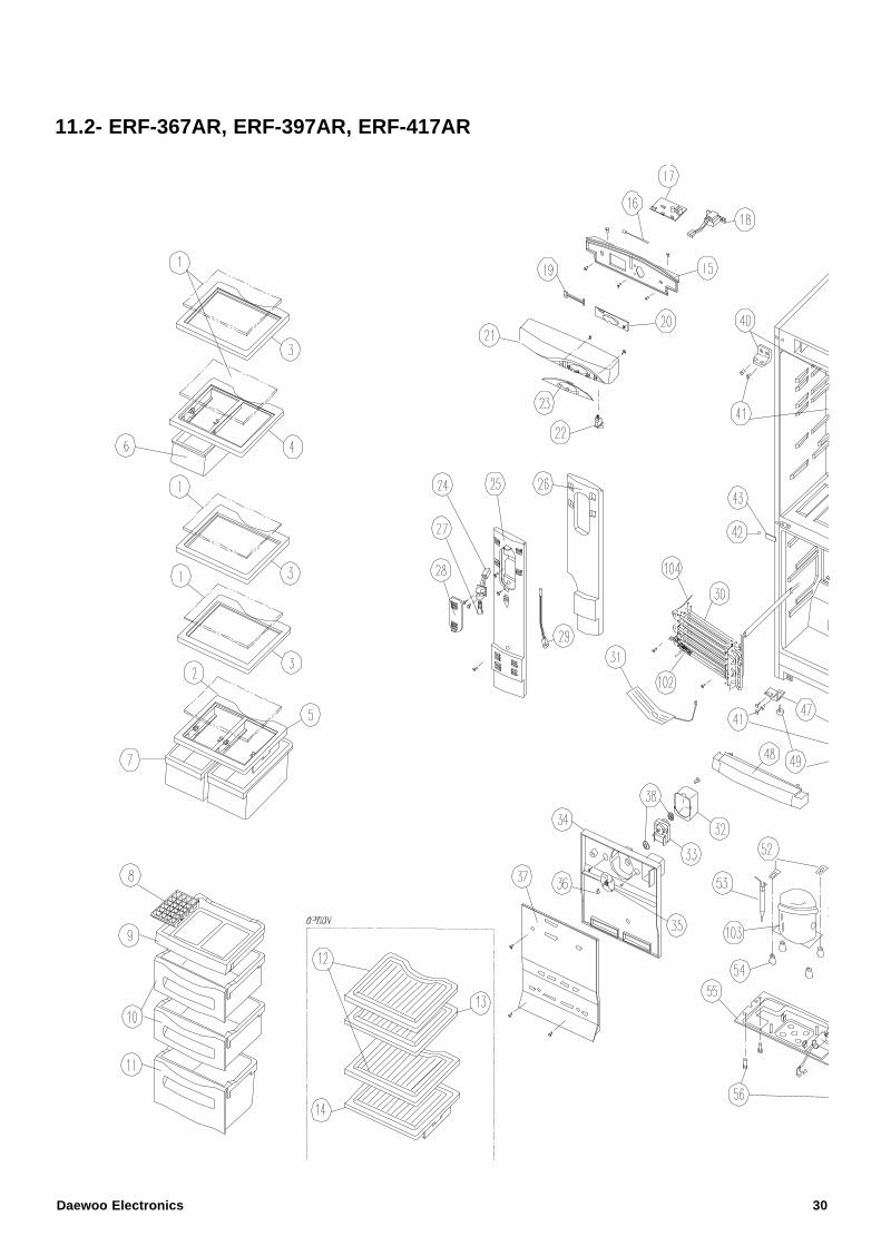
11.2- ERF-367AR, ERF-397AR, ERF-417AR
Daewoo Electronics 30
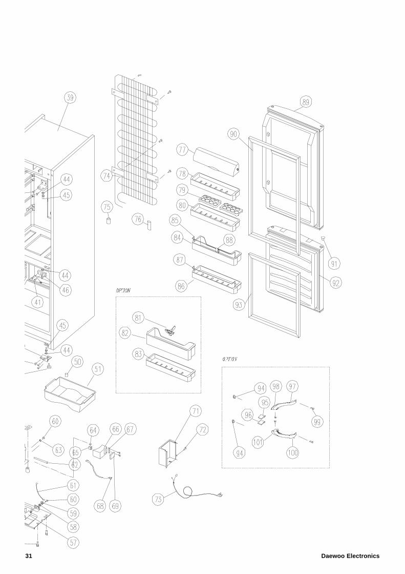
31 Daewoo Electronics
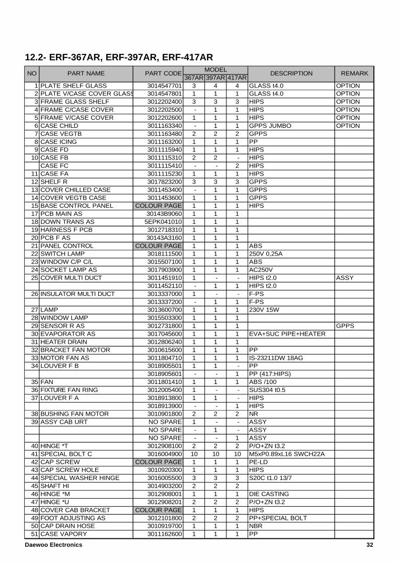
12.2- ERF-367AR, ERF-397AR, ERF-417AR
367AR 397AR 417AR1 PLATE SHELF GLASS 3014547701 3 4 4 GLASS t4.0 OPTION2 PLATE V/CASE COVER GLASS 3014547801 1 1 1 GLASS t4.0 OPTION3 FRAME GLASS SHELF 3012202400 3 3 3 HIPS OPTION4 FRAME C/CASE COVER 3012202500 - 1 1 HIPS OPTION5 FRAME V/CASE COVER 3012202600 1 1 1 HIPS OPTION6 CASE CHILD 3011163340 - 1 1 GPPS JUMBO OPTION7 CASE VEGTB 3011163480 2 2 2 GPPS8 CASE ICING 3011163200 1 1 1 PP9 CASE FD 3011115940 1 1 1 HIPS
10 CASE FB 3011115310 2 2 - HIPSCASE FC 3011115410 - - 2 HIPS
11 CASE FA 3011115230 1 1 1 HIPS12 SHELF R 3017823200 3 3 3 GPPS13 COVER CHILLED CASE 3011453400 - 1 1 GPPS14 COVER VEGTB CASE 3011453600 1 1 1 GPPS15 BASE CONTROL PANEL COLOUR PAGE 1 1 1 HIPS17 PCB MAIN AS 30143B9060 1 1 118 DOWN TRANS AS 5EPK041010 1 1 119 HARNESS F PCB 3012718310 1 1 120 PCB F AS 30143A3160 1 1 121 PANEL CONTROL COLOUR PAGE 1 1 1 ABS22 SWITCH LAMP 3018111500 1 1 1 250V 0,25A23 WINDOW C/P C/L 3015507100 1 1 1 ABS24 SOCKET LAMP AS 3017903900 1 1 1 AC250V25 COVER MULTI DUCT 3011451910 1 - - HIPS t2.0 ASSY
3011452110 - 1 1 HIPS t2.026 INSULATOR MULTI DUCT 3013337000 1 - - F-PS
3013337200 - 1 1 F-PS27 LAMP 3013600700 1 1 1 230V 15W28 WINDOW LAMP 3015503300 1 1 129 SENSOR R AS 3012731800 1 1 1 GPPS30 EVAPORATOR AS 3017045600 1 1 1 EVA+SUC PIPE+HEATER31 HEATER DRAIN 3012806240 1 1 132 BRACKET FAN MOTOR 3010615600 1 1 1 PP33 MOTOR FAN AS 3011804710 1 1 1 IS-23211DW 18AG34 LOUVER F B 3018905501 1 1 - PP
3018905601 - - 1 PP (417:HIPS)35 FAN 3011801410 1 1 1 ABS /10036 FIXTURE FAN RING 3012005400 1 - - SUS304 t0.537 LOUVER F A 3018913800 1 1 - HIPS
3018913900 - - 1 HIPS38 BUSHING FAN MOTOR 3010901800 2 2 2 NR39 ASSY CAB URT NO SPARE 1 - - ASSY
NO SPARE - 1 - ASSY NO SPARE - - 1 ASSY
40 HINGE *T 3012908100 2 2 2 P/O+ZN t3.241 SPECIAL BOLT C 3016004900 10 10 10 M5xP0.89xL16 SWCH22A42 CAP SCREW COLOUR PAGE 1 1 1 PE-LD43 CAP SCREW HOLE 3010920300 1 1 1 HIPS44 SPECIAL WASHER HINGE 3016005500 3 3 3 S20C t1.0 13/745 SHAFT HI 3014903200 2 2 246 HINGE *M 3012908001 1 1 1 DIE CASTING47 HINGE *U 3012908201 2 2 2 P/O+ZN t3.248 COVER CAB BRACKET COLOUR PAGE 1 1 1 HIPS49 FOOT ADJUSTING AS 3012101800 2 2 2 PP+SPECIAL BOLT50 CAP DRAIN HOSE 3010919700 1 1 1 NBR51 CASE VAPORY 3011162600 1 1 1 PP
DESCRIPTION REMARKMODEL
NO PART NAME PART CODE
Daewoo Electronics 32
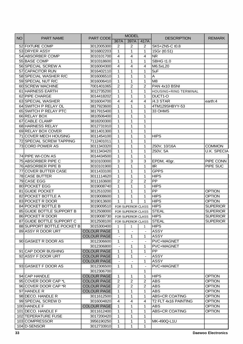
367A 397A 417A52 FIXTURE COMP 3012005300 2 2 2 SK5+ZN5-C t0.853 DRYER ASSY 3016802203 1 1 1 15Gr (t0.51)54 ABSORBER COMP 3010101700 4 4 4 NR55 BASE COMP 3010318600 1 1 1 SBHG t1.056 SPECIAL SCREW A 3016004300 4 4 4 M6.5xL2057 CAPACITOR RUN 3016402110 1 1 1 5uF58 SPECIAL WASHER R/C 3016006510 1 1 1 A59 SPECIAL NUT R/C 3016006410 1 1 1 M860 SCREW MACHINE 7001401065 2 2 2 PAN 4x10 BSNI61 HARNESS EARTH 3012735200 1 1 1 HOUSING+RING TERMINAL62 PIPE CHARGE 3014418202 1 1 1 DUCT1-O63 SPECIAL WASHER 3016004700 4 4 4 /4.3 STAR earth:464 SWITCH P RELAY OL 3817923600 1 1 1 4TM129SHBYY-5365 SWITCH P RELAY PTC 3817915400 1 1 1 33 OHMS66 RELAY BOX 3810506400 1 1 167 CABLE CLAMP 3818200300 1 1 168 HARNESS RELAY 3012731910 1 1 169 RELAY BOX COVER 3811401300 1 1 171 COVER MECH HOUSING 3011454100 1 1 1 HIPS72 SPECIAL SCREW TAPPING 7112401011 1 1 173 CORD POWER AS 3011343320 1 1 1 250V, 10/16A COMMON
3011343420 1 1 1 250V, 5A U.K. SPECIAL74 PIPE WI-CON AS 3014434500 1 1 175 ABSORBER PIPE C 3010103000 3 3 3 EPDM, 40gr. PIPE CONN76 ABSORBER PIPE B 3010101900 1 1 1 IIR PIPE SUC77 COVER BUTTER CASE 3011433100 1 1 1 GPPS78 CASE BUTTER 3011114620 1 1 1 HIPS79 CASE EGG 3011163600 2 2 2 PP80 POCKET EGG 3019008740 1 1 1 HIPS81 GUIDE POCKET 3012510200 1 1 1 PP OPTION82 POCKET BOTTLE A 3019008600 1 1 1 HIPS OPTION83 POCKET R DOOR 3019013600 1 1 1 HIPS OPTION84 POCKET BOTTLE B 3019009510 HIPS SUPERIOR85 GUIDE BOTTLE SUPPORT B 3012508000 STEAL SUPERIOR86 POCKET R DOOR 3019008730 HIPS SUPERIOR87 GUIDE BOTTLE SUPPORT C 3012508100 STEAL SUPERIOR88 SUPPORT BOTTLE POCKET B 3015300400 1 1 1 HIPS89 ASSY R DOOR URT COLOUR PAGE 1 - - ASSY
COLOUR PAGE - 1 1 ASSY90 GASKET R DOOR AS 3012306600 1 - - PVC+MAGNET
3012306800 - 1 1 PVC+MAGNET91 CAP DOOR BUSHING COLOUR PAGE 1 1 1 PP92 ASSY F DOOR URT COLOUR PAGE 1 1 - ASSY
COLOUR PAGE - - 1 ASSY93 GASKET F DOOR AS 3012306500 1 1 - PVC+MAGNET
3012306700 194 CAP HANDLE COLOUR PAGE 1 1 1 HIPS OPTION95 COVER DOOR CAP *L COLOUR PAGE 2 2 2 ABS OPTION96 COVER DOOR CAP *R COLOUR PAGE 2 2 2 ABS OPTION97 HANDLE R COLOUR PAGE 1 1 1 ABS OPTION98 DECO. HANDLE R 3011612500 1 1 1 ABS+CR COATING OPTION99 SPECIAL SCREW D 3016004820 4 4 4 T2 FLT 4x16 PAINTING OPTION
100 HANDLE F COLOUR PAGE 1 1 1 ABS OPTION101 DECO. HANDLE F 3011612400 1 1 1 ABS+CR COATING OPTION102 TEPERATURE FUSE 3017200420 1 1 1103 COMPRESSOR 3956190250 1 1 1 MK-490Q-L1U104 D-SENSOR 3012733910 1 1 1
FOR SUPERIOR CLASS
FOR SUPERIOR CLASS
FOR SUPERIOR CLASS
FOR SUPERIOR CLASS
DESCRIPTION REMARKMODEL
NO PART NAME PART CODE
33 Daewoo Electronics
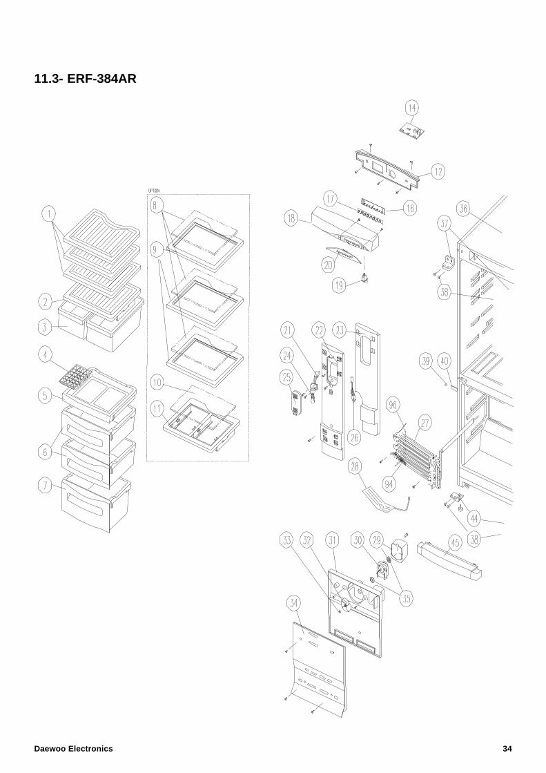
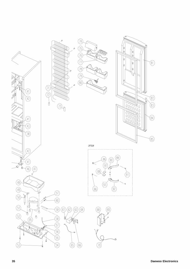
11.3- ERF-384AR
Daewoo Electronics 34
35 Daewoo Electronics
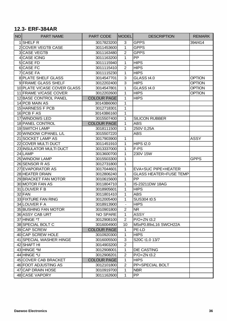
12.3- ERF-384AR
1 SHELF R 3017823200 3 GPPS 394/4142 COVER VEGTB CASE 3011453600 1 GPPS3 CASE VEGTB 3011163480 2 GPPS4 CASE ICING 3011163200 1 PP5 CASE FD 3011115940 1 HIPS6 CASE FC 3011115410 2 HIPS7 CASE FA 3011115230 1 HIPS8 PLATE SHELF GLASS 3014547701 3 GLASS t4.0 OPTION9 FRAME GLASS SHELF 3012202400 3 HIPS OPTION
10 PLATE V/CASE COVER GLASS 3014547801 1 GLASS t4.0 OPTION11 FRAME V/CASE COVER 3012202600 1 HIPS OPTION12 BASE CONTROL PANEL COLOUR PAGE 1 HIPS14 PCB MAIN AS 30143B6060 115 HARNESS F PCB 3012718301 116 PCB F AS 30143B6160 117 WINDOWS LED 3015507400 1 SILICON RUBBER18 PANEL CONTROL COLOUR PAGE 1 ABS19 SWITCH LAMP 3018111500 1 250V 0,25A20 WINDOW C/PANEL L/L 3015507220 ABS21 SOCKET LAMP AS 3017903900 1 ASSY22 COVER MULTI DUCT 3011451910 1 HIPS t2.023 INSULATOR MULTI DUCT 3013337000 1 F-PS24 LAMP 3013600700 1 230V 15W25 WINDOW LAMP 3015503300 1 GPPS26 SENSOR R AS 3012731800 127 EVAPORATOR AS 3017044601 1 EVA+SUC PIPE+HEATER28 HEATER DRAIN 3012806240 1 GLASS HEATER+FUSE TEMP29 BRACKET FAN MOTOR 3010615600 1 PP30 MOTOR FAN AS 3011804710 1 IS-23211DW 18AG31 LOUVER F B 3018905601 1 HIPS32 FAN 3011801410 1 ABS33 FIXTURE FAN RING 3012005400 1 SUS304 t0.534 LOUVER F A 3018913900 - HIPS35 BUSHING FAN MOTOR 3010901800 2 NR36 ASSY CAB URT NO SPARE 1 ASSY 37 HINGE *T 3012908100 2 P/O+ZN t3.238 SPECIAL BOLT C 3016004900 10 M5xP0.89xL16 SWCH22A39 CAP SCREW COLOUR PAGE 1 PE-LD40 CAP SCREW HOLE 3010920300 1 HIPS41 SPECIAL WASHER HINGE 3016005500 3 S20C t1.0 13/742 SHAFT HI 3014903200 243 HINGE *M 3012908001 1 DIE CASTING44 HINGE *U 3012908201 2 P/O+ZN t3.245 COVER CAB BRACKET COLOUR PAGE 1 HIPS46 FOOT ADJUSTING AS 3012101800 2 PP+SPECIAL BOLT47 CAP DRAIN HOSE 3010919700 1 NBR48 CASE VAPORY 3011162600 1 PP
DESCRIPTION REMARKNO PART NAME PART CODE MODEL
Daewoo Electronics 36
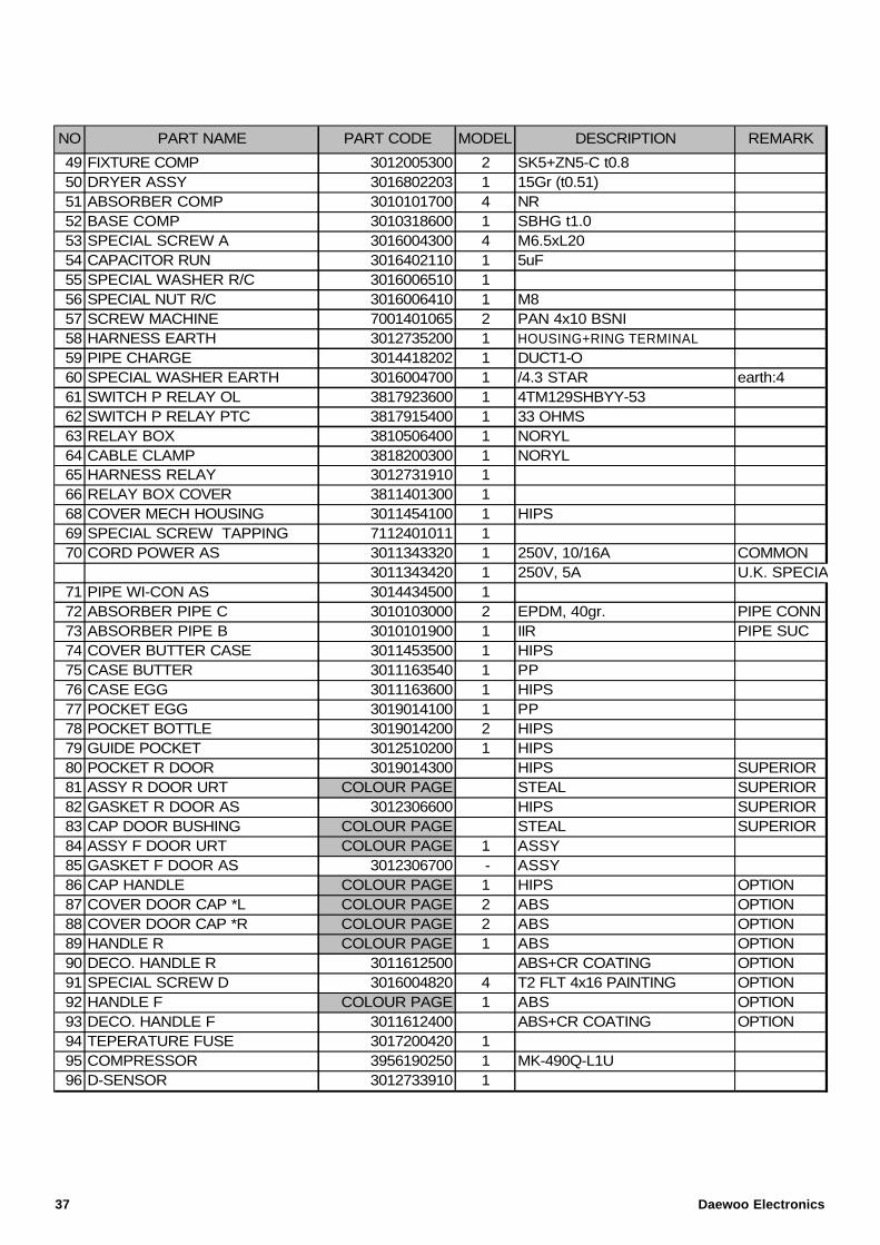
49 FIXTURE COMP 3012005300 2 SK5+ZN5-C t0.850 DRYER ASSY 3016802203 1 15Gr (t0.51)51 ABSORBER COMP 3010101700 4 NR52 BASE COMP 3010318600 1 SBHG t1.053 SPECIAL SCREW A 3016004300 4 M6.5xL2054 CAPACITOR RUN 3016402110 1 5uF55 SPECIAL WASHER R/C 3016006510 156 SPECIAL NUT R/C 3016006410 1 M857 SCREW MACHINE 7001401065 2 PAN 4x10 BSNI58 HARNESS EARTH 3012735200 1 HOUSING+RING TERMINAL59 PIPE CHARGE 3014418202 1 DUCT1-O60 SPECIAL WASHER EARTH 3016004700 1 /4.3 STAR earth:461 SWITCH P RELAY OL 3817923600 1 4TM129SHBYY-5362 SWITCH P RELAY PTC 3817915400 1 33 OHMS63 RELAY BOX 3810506400 1 NORYL64 CABLE CLAMP 3818200300 1 NORYL65 HARNESS RELAY 3012731910 166 RELAY BOX COVER 3811401300 168 COVER MECH HOUSING 3011454100 1 HIPS69 SPECIAL SCREW TAPPING 7112401011 170 CORD POWER AS 3011343320 1 250V, 10/16A COMMON
3011343420 1 250V, 5A U.K. SPECIAL71 PIPE WI-CON AS 3014434500 172 ABSORBER PIPE C 3010103000 2 EPDM, 40gr. PIPE CONN73 ABSORBER PIPE B 3010101900 1 IIR PIPE SUC74 COVER BUTTER CASE 3011453500 1 HIPS75 CASE BUTTER 3011163540 1 PP76 CASE EGG 3011163600 1 HIPS77 POCKET EGG 3019014100 1 PP78 POCKET BOTTLE 3019014200 2 HIPS79 GUIDE POCKET 3012510200 1 HIPS80 POCKET R DOOR 3019014300 HIPS SUPERIOR81 ASSY R DOOR URT COLOUR PAGE STEAL SUPERIOR82 GASKET R DOOR AS 3012306600 HIPS SUPERIOR83 CAP DOOR BUSHING COLOUR PAGE STEAL SUPERIOR84 ASSY F DOOR URT COLOUR PAGE 1 ASSY85 GASKET F DOOR AS 3012306700 - ASSY86 CAP HANDLE COLOUR PAGE 1 HIPS OPTION87 COVER DOOR CAP *L COLOUR PAGE 2 ABS OPTION88 COVER DOOR CAP *R COLOUR PAGE 2 ABS OPTION89 HANDLE R COLOUR PAGE 1 ABS OPTION90 DECO. HANDLE R 3011612500 ABS+CR COATING OPTION91 SPECIAL SCREW D 3016004820 4 T2 FLT 4x16 PAINTING OPTION92 HANDLE F COLOUR PAGE 1 ABS OPTION93 DECO. HANDLE F 3011612400 ABS+CR COATING OPTION94 TEPERATURE FUSE 3017200420 195 COMPRESSOR 3956190250 1 MK-490Q-L1U96 D-SENSOR 3012733910 1
MODELNO PART NAME PART CODE DESCRIPTION REMARK
37 Daewoo Electronics
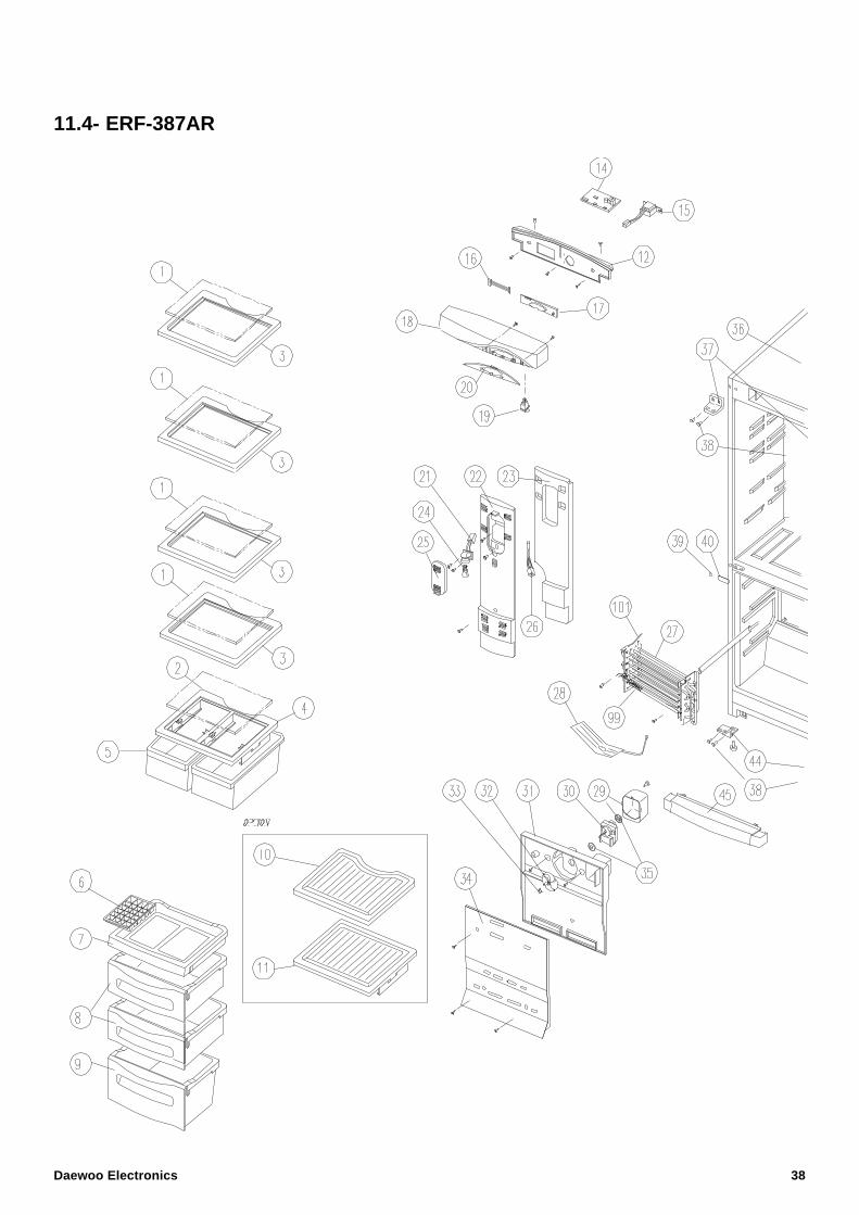
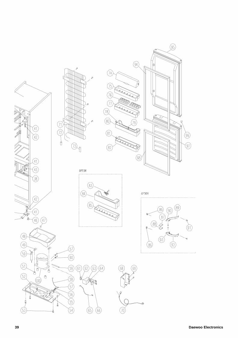
11.4- ERF-387AR
Daewoo Electronics 38
39 Daewoo Electronics
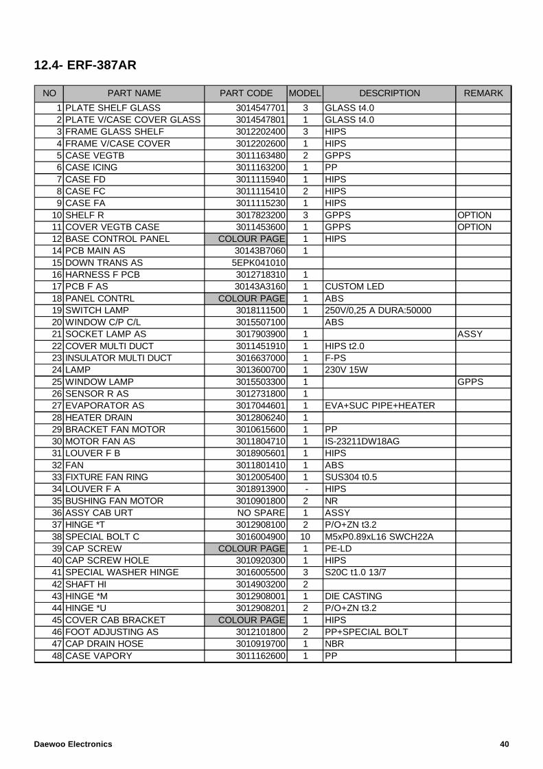
12.4- ERF-387AR
1 PLATE SHELF GLASS 3014547701 3 GLASS t4.02 PLATE V/CASE COVER GLASS 3014547801 1 GLASS t4.03 FRAME GLASS SHELF 3012202400 3 HIPS4 FRAME V/CASE COVER 3012202600 1 HIPS5 CASE VEGTB 3011163480 2 GPPS6 CASE ICING 3011163200 1 PP7 CASE FD 3011115940 1 HIPS8 CASE FC 3011115410 2 HIPS9 CASE FA 3011115230 1 HIPS
10 SHELF R 3017823200 3 GPPS OPTION11 COVER VEGTB CASE 3011453600 1 GPPS OPTION12 BASE CONTROL PANEL COLOUR PAGE 1 HIPS14 PCB MAIN AS 30143B7060 115 DOWN TRANS AS 5EPK04101016 HARNESS F PCB 3012718310 117 PCB F AS 30143A3160 1 CUSTOM LED18 PANEL CONTRL COLOUR PAGE 1 ABS19 SWITCH LAMP 3018111500 1 250V/0,25 A DURA:5000020 WINDOW C/P C/L 3015507100 ABS21 SOCKET LAMP AS 3017903900 1 ASSY22 COVER MULTI DUCT 3011451910 1 HIPS t2.023 INSULATOR MULTI DUCT 3016637000 1 F-PS24 LAMP 3013600700 1 230V 15W25 WINDOW LAMP 3015503300 1 GPPS26 SENSOR R AS 3012731800 127 EVAPORATOR AS 3017044601 1 EVA+SUC PIPE+HEATER28 HEATER DRAIN 3012806240 129 BRACKET FAN MOTOR 3010615600 1 PP30 MOTOR FAN AS 3011804710 1 IS-23211DW18AG31 LOUVER F B 3018905601 1 HIPS32 FAN 3011801410 1 ABS33 FIXTURE FAN RING 3012005400 1 SUS304 t0.534 LOUVER F A 3018913900 - HIPS35 BUSHING FAN MOTOR 3010901800 2 NR36 ASSY CAB URT NO SPARE 1 ASSY 37 HINGE *T 3012908100 2 P/O+ZN t3.238 SPECIAL BOLT C 3016004900 10 M5xP0.89xL16 SWCH22A39 CAP SCREW COLOUR PAGE 1 PE-LD40 CAP SCREW HOLE 3010920300 1 HIPS41 SPECIAL WASHER HINGE 3016005500 3 S20C t1.0 13/742 SHAFT HI 3014903200 243 HINGE *M 3012908001 1 DIE CASTING44 HINGE *U 3012908201 2 P/O+ZN t3.245 COVER CAB BRACKET COLOUR PAGE 1 HIPS46 FOOT ADJUSTING AS 3012101800 2 PP+SPECIAL BOLT47 CAP DRAIN HOSE 3010919700 1 NBR48 CASE VAPORY 3011162600 1 PP
NO PART NAME PART CODE MODEL DESCRIPTION REMARK
Daewoo Electronics 40
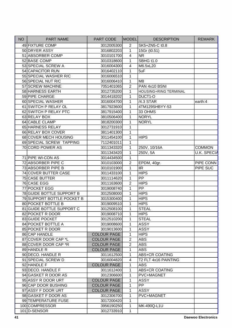
49 FIXTURE COMP 3012005300 2 SK5+ZN5-C t0.850 DRYER ASSY 3016802203 1 15Gr (t0.51)51 ABSORBER COMP 3010101700 4 NR52 BASE COMP 3010318600 1 SBHG t1.053 SPECIAL SCREW A 3016004300 4 M6.5xL2054 CAPACITOR RUN 3016402110 1 5uF55 SPECIAL WASHER R/C 3016006510 156 SPECIAL NUT R/C 3016006410 1 M857 SCREW MACHINE 7051401065 2 PAN 4x10 BSNI58 HARNESS EARTH 3012735200 1 HOUSING+RING TERMINAL59 PIPE CHARGE 3014418202 1 DUCT1-O60 SPECIAL WASHER 3016004700 1 /4.3 STAR earth:461 SWITCH P RELAY OL 3817923600 1 4TM129SHBYY-5362 SWITCH P RELAY PTC 3817915400 1 33 OHMS63 RELAY BOX 3810506400 1 NORYL64 CABLE CLAMP 3818200300 1 NORYL65 HARNESS RELAY 3012731910 166 RELAY BOX COVER 3811401300 168 COVER MECH HOUSING 3011454100 1 HIPS69 SPECIAL SCREW TAPPING 7112401011 170 CORD POWER AS 3011343320 1 250V, 10/16A COMMON
3011343420 1 250V, 5A U.K. SPECIAL71 PIPE WI-CON AS 3014434500 172 ABSORBER PIPE C 3010103000 2 EPDM, 40gr. PIPE CONN73 ABSORBER PIPE B 3010101900 1 IIR PIPE SUC74 COVER BUTTER CASE 3011433100 1 HIPS75 CASE BUTTER 3011114620 1 PP76 CASE EGG 3011163600 2 HIPS77 POCKET EGG 3019008740 1 PP78 GUIDE BOTTLE SUPPORT B 3012508000 1 HIPS79 SUPPORT BOTTLE POCKET B 3015300400 1 HIPS80 POCKET BOTTLE B 3019009510 1 HIPS81 GUIDE BOTTLE SUPPORT C 3012508100 1 STEAL82 POCKET R DOOR 3019008710 1 HIPS83 GUIDE POCKET 3012510200 1 STEAL84 POCKET BOTTLE A 3019008600 1 ASSY85 POCKET R DOOR 3019013600 1 ASSY86 CAP HANDLE COLOUR PAGE 1 HIPS87 COVER DOOR CAP *L COLOUR PAGE 2 ABS88 COVER DOOR CAP *R COLOUR PAGE 2 ABS89 HANDLE R COLOUR PAGE 1 ABS90 DECO. HANDLE R 3011612500 1 ABS+CR COATING91 SPECIAL SCREW D 3016004820 4 T2 FLT 4x16 PAINTING92 HANDLE F COLOUR PAGE 1 ABS93 DECO. HANDLE F 3011612400 1 ABS+CR COATING94 GASKET R DOOR AS 3012306600 1 PVC+MAGNET95 ASSY R DOOR URT COLOUR PAGE 1 ASSY96 CAP DOOR BUSHING COLOUR PAGE 1 PP97 ASSY F DOOR URT COLOUR PAGE 1 ASSY98 GASKET F DOOR AS 3012306700 1 PVC+MAGNET99 TEMPERATURE FUSE 3017200420 1
100 COMPRESSOR 3956190250 1 MK-490Q-L1U101 D-SENSOR 3012733910 1
MODELNO PART NAME PART CODE DESCRIPTION REMARK
41 Daewoo Electronics
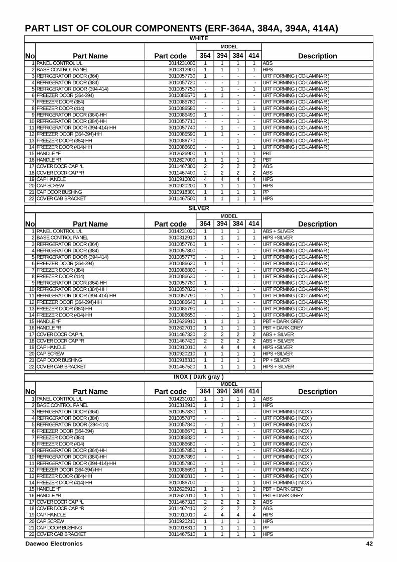
PART LIST OF COLOUR COMPONENTS (ERF-364A, 384A, 394A, 414A)
364 394 384 4141 PANEL CONTROL L/L 3014231000 1 1 1 1 ABS2 BASE CONTROL PANEL 3010312900 1 1 1 1 HIPS3 REFRIGERATOR DOOR (364) 3010057730 1 - - - URT FORMING ( CO-LAMINAR )4 REFRIGERATOR DOOR (384) 3010057720 - - 1 - URT FORMING ( CO-LAMINAR )5 REFRIGERATOR DOOR (394-414) 3010057750 - 1 - 1 URT FORMING ( CO-LAMINAR )6 FREEZER DOOR (364-394) 3010086570 1 1 - - URT FORMING ( CO-LAMINAR )7 FREEZER DOOR (384) 3010086780 - - 1 - URT FORMING ( CO-LAMINAR )8 FREEZER DOOR (414) 3010086580 - - 1 1 URT FORMING ( CO-LAMINAR )9 REFRIGERATOR DOOR (364)-HH 3010086490 1 - - - URT FORMING ( CO-LAMINAR )
10 REFRIGERATOR DOOR (384)-HH 3010057710 - - 1 - URT FORMING ( CO-LAMINAR )11 REFRIGERATOR DOOR (394-414)-HH 3010057740 - 1 - 1 URT FORMING ( CO-LAMINAR )12 FREEZER DOOR (364-394)-HH 3010086590 1 1 - - URT FORMING ( CO-LAMINAR )13 FREEZER DOOR (384)-HH 3010086770 - - 1 - URT FORMING ( CO-LAMINAR )14 FREEZER DOOR (414)-HH 3010086600 - - 1 1 URT FORMING ( CO-LAMINAR )15 HANDLE *F 3012626900 1 1 1 1 PBT 16 HANDLE *R 3012627000 1 1 1 1 PBT17 COVER DOOR CAP *L 3011467300 2 2 2 2 ABS18 COVER DOOR CAP *R 3011467400 2 2 2 2 ABS19 CAP HANDLE 3010910000 4 4 4 4 HIPS 20 CAP SCREW 3010920200 1 1 1 1 HIPS21 CAP DOOR BUSHING 3010918301 1 1 1 1 PP22 COVER CAB BRACKET 3011467500 1 1 1 1 HIPS
364 394 384 4141 PANEL CONTROL L/L 3014231020 1 1 1 1 ABS + SLIVER2 BASE CONTROL PANEL 3010312910 1 1 1 1 HIPS +SILVER3 REFRIGERATOR DOOR (364) 3010057760 1 - - - URT FORMING ( CO-LAMINAR )4 REFRIGERATOR DOOR (384) 3010057800 - - 1 - URT FORMING ( CO-LAMINAR )5 REFRIGERATOR DOOR (394-414) 3010057770 - 1 - 1 URT FORMING ( CO-LAMINAR )6 FREEZER DOOR (364-394) 3010086620 1 1 - - URT FORMING ( CO-LAMINAR )7 FREEZER DOOR (384) 3010086800 - - 1 - URT FORMING ( CO-LAMINAR )8 FREEZER DOOR (414) 3010086630 - - 1 1 URT FORMING ( CO-LAMINAR )9 REFRIGERATOR DOOR (364)-HH 3010057780 1 - - - URT FORMING ( CO-LAMINAR )
10 REFRIGERATOR DOOR (384)-HH 3010057820 - - 1 - URT FORMING ( CO-LAMINAR )11 REFRIGERATOR DOOR (394-414)-HH 3010057790 - 1 - 1 URT FORMING ( CO-LAMINAR )12 FREEZER DOOR (364-394)-HH 3010086640 1 1 - - URT FORMING ( CO-LAMINAR )13 FREEZER DOOR (384)-HH 3010086790 - - 1 - URT FORMING ( CO-LAMINAR )14 FREEZER DOOR (414)-HH 3010086650 - - 1 1 URT FORMING ( CO-LAMINAR )15 HANDLE *F 3012626910 1 1 1 1 PBT + DARK GREY16 HANDLE *R 3012627010 1 1 1 1 PBT + DARK GREY17 COVER DOOR CAP *L 3011467320 2 2 2 2 ABS + SILVER18 COVER DOOR CAP *R 3011467420 2 2 2 2 ABS + SILVER19 CAP HANDLE 3010910010 4 4 4 4 HIPS +SILVER20 CAP SCREW 3010920210 1 1 1 1 HIPS +SILVER21 CAP DOOR BUSHING 3010918310 1 1 1 1 PP + SILVER22 COVER CAB BRACKET 3011467520 1 1 1 1 HIPS + SILVER
364 394 384 4141 PANEL CONTROL L/L 3014231010 1 1 1 1 ABS2 BASE CONTROL PANEL 3010312910 1 1 1 1 HIPS3 REFRIGERATOR DOOR (364) 3010057830 1 - - - URT FORMING ( INOX )4 REFRIGERATOR DOOR (384) 3010057870 - - 1 - URT FORMING ( INOX )5 REFRIGERATOR DOOR (394-414) 3010057840 - 1 - 1 URT FORMING ( INOX )6 FREEZER DOOR (364-394) 3010086670 1 1 - - URT FORMING ( INOX )7 FREEZER DOOR (384) 3010086820 - - 1 - URT FORMING ( INOX )8 FREEZER DOOR (414) 3010086680 - - 1 1 URT FORMING ( INOX )9 REFRIGERATOR DOOR (364)-HH 3010057850 1 - - - URT FORMING ( INOX )
10 REFRIGERATOR DOOR (384)-HH 3010057890 - - 1 - URT FORMING ( INOX )11 REFRIGERATOR DOOR (394-414)-HH 3010057860 - 1 - 1 URT FORMING ( INOX )12 FREEZER DOOR (364-394)-HH 3010086690 1 1 - - URT FORMING ( INOX )13 FREEZER DOOR (384)-HH 3010086810 - - 1 - URT FORMING ( INOX )14 FREEZER DOOR (414)-HH 3010086700 - - 1 1 URT FORMING ( INOX )15 HANDLE *F 3012626910 1 1 1 1 PBT + DARK GREY16 HANDLE *R 3012627010 1 1 1 1 PBT + DARK GREY17 COVER DOOR CAP *L 3011467310 2 2 2 2 ABS18 COVER DOOR CAP *R 3011467410 2 2 2 2 ABS19 CAP HANDLE 3010910010 4 4 4 4 HIPS20 CAP SCREW 3010920210 1 1 1 1 HIPS21 CAP DOOR BUSHING 3010918310 1 1 1 1 PP22 COVER CAB BRACKET 3011467510 1 1 1 1 HIPS
Part Name Part code Description
No Part Name Part code DescriptionMODEL
WHITE
SILVER
INOX ( Dark gray )
MODEL
MODEL
Part code
No
DescriptionNo Part Name
Daewoo Electronics 42
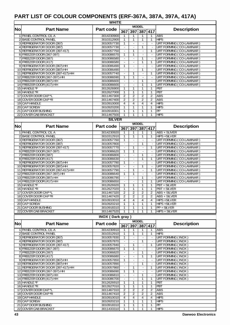
PART LIST OF COLOUR COMPONENTS (ERF-367A, 387A, 397A, 417A)
367 397 387 4171 PANEL CONTROL C/L A 3014230900 1 1 1 1 ABS2 BASE CONTROL PANEL 3010312900 1 1 1 1 HIPS3 REFRIGERATOR DOOR (367) 3010057730 1 - - - URT FORMING ( CO-LAMINAR )4 REFRIGERATOR DOOR (387) 3010057730 - - 1 - URT FORMING ( CO-LAMINAR )5 REFRIGERATOR DOOR (397-417) 3010057750 - 1 - 1 URT FORMING ( CO-LAMINAR )6 FREEZER DOOR (367-397) 3010086570 1 1 - - URT FORMING ( CO-LAMINAR )7 FREEZER DOOR (387) 3010086580 - - 1 - URT FORMING ( CO-LAMINAR )8 FREEZER DOOR (417) 3010086580 - - 1 1 URT FORMING ( CO-LAMINAR )9 REFRIGERATOR DOOR (367)-HH 3010086490 1 - - - URT FORMING ( CO-LAMINAR )
10 REFRIGERATOR DOOR (387)-HH 3010086490 - - 1 - URT FORMING ( CO-LAMINAR )11 REFRIGERATOR DOOR (397-417)-HH 3010057740 - 1 - 1 URT FORMING ( CO-LAMINAR )12 FREEZER DOOR (367-397)-HH 3010086590 1 1 - - URT FORMING ( CO-LAMINAR )13 FREEZER DOOR (387)-HH 3010086600 - - 1 - URT FORMING ( CO-LAMINAR )14 FREEZER DOOR (417)-HH 3010086600 - - 1 1 URT FORMING ( CO-LAMINAR )15 HANDLE *F 3012626900 1 1 1 1 PBT 16 HANDLE *R 3012627000 1 1 1 1 PBT17 COVER DOOR CAP *L 3011467300 2 2 2 2 ABS18 COVER DOOR CAP *R 3011467400 2 2 2 2 ABS19 CAP HANDLE 3010910000 4 4 4 4 HIPS 20 CAP SCREW 3010920200 1 1 1 1 HIPS21 CAP DOOR BUSHING 3010918301 1 1 1 1 PP22 COVER CAB BRACKET 3011467500 1 1 1 1 HIPS
367 397 387 4171 PANEL CONTROL C/L A 3014230920 1 1 1 1 ABS + SLIVER2 BASE CONTROL PANEL 3010312910 1 1 1 1 HIPS +SILVER3 REFRIGERATOR DOOR (367) 3010057760 1 - - - URT FORMING ( CO-LAMINAR )4 REFRIGERATOR DOOR (387) 3010057800 - - 1 - URT FORMING ( CO-LAMINAR )5 REFRIGERATOR DOOR (397-417) 3010057770 - 1 - 1 URT FORMING ( CO-LAMINAR )6 FREEZER DOOR (367-397) 3010086620 1 1 - - URT FORMING ( CO-LAMINAR )7 FREEZER DOOR (387) 3010086800 - - 1 - URT FORMING ( CO-LAMINAR )8 FREEZER DOOR (417) 3010086630 - - 1 1 URT FORMING ( CO-LAMINAR )9 REFRIGERATOR DOOR (367)-HH 3010057780 1 - - - URT FORMING ( CO-LAMINAR )
10 REFRIGERATOR DOOR (387)-HH 3010057820 - - 1 - URT FORMING ( CO-LAMINAR )11 REFRIGERATOR DOOR (397-417)-HH 3010057790 - 1 - 1 URT FORMING ( CO-LAMINAR )12 FREEZER DOOR (367-397)-HH 3010086640 1 1 - - URT FORMING ( CO-LAMINAR )13 FREEZER DOOR (387)-HH 3010086790 - - 1 - URT FORMING ( CO-LAMINAR )14 FREEZER DOOR (417)-HH 3010086650 - - 1 1 URT FORMING ( CO-LAMINAR )15 HANDLE *F 3012626920 1 1 1 1 PBT + SILVER16 HANDLE *R 3012627020 1 1 1 1 PBT + SILVER17 COVER DOOR CAP *L 3011467320 2 2 2 2 ABS + SILVER18 COVER DOOR CAP *R 3011467420 2 2 2 2 ABS + SILVER19 CAP HANDLE 3010910010 4 4 4 4 HIPS +SILVER20 CAP SCREW 3010920210 1 1 1 1 HIPS +SILVER21 CAP DOOR BUSHING 3010918310 1 1 1 1 PP + SILVER22 COVER CAB BRACKET 3011467520 1 1 1 1 HIPS + SILVER
367 397 387 4171 PANEL CONTROL C/L A 3014230910 1 1 1 1 ABS2 BASE CONTROL PANEL 3010312910 1 1 1 1 HIPS3 REFRIGERATOR DOOR (367) 3010057830 1 - - - URT FORMING ( INOX )4 REFRIGERATOR DOOR (387) 3010057870 - - 1 - URT FORMING ( INOX )5 REFRIGERATOR DOOR (397-417) 3010057840 - 1 - 1 URT FORMING ( INOX )6 FREEZER DOOR (367-397) 3010086670 1 1 - - URT FORMING ( INOX )7 FREEZER DOOR (387) 3010086820 - - 1 - URT FORMING ( INOX )8 FREEZER DOOR (417) 3010086680 - - 1 1 URT FORMING ( INOX )9 REFRIGERATOR DOOR (367)-HH 3010057850 1 - - - URT FORMING ( INOX )
10 REFRIGERATOR DOOR (387)-HH 3010057890 - - 1 - URT FORMING ( INOX )11 REFRIGERATOR DOOR (397-417)-HH 3010057860 - 1 - 1 URT FORMING ( INOX )12 FREEZER DOOR (367-397)-HH 3010086690 1 1 - - URT FORMING ( INOX )13 FREEZER DOOR (387)-HH 3010086810 - - 1 - URT FORMING ( INOX )14 FREEZER DOOR (417)-HH 3010086700 - - 1 1 URT FORMING ( INOX )15 HANDLE *F 3012626910 1 1 1 1 PBT16 HANDLE *R 3012627010 1 1 1 1 PBT17 COVER DOOR CAP *L 3011467310 2 2 2 2 ABS18 COVER DOOR CAP *R 3011467410 2 2 2 2 ABS19 CAP HANDLE 3010910010 4 4 4 4 HIPS20 CAP SCREW 3010920210 1 1 1 1 HIPS21 CAP DOOR BUSHING 3010918310 1 1 1 1 PP22 COVER CAB BRACKET 3011433310 1 1 1 1 HIPS
WHITE
SILVER
INOX ( Dark gray )
MODEL
MODEL
Part code
No
DescriptionNo Part Name
Part Name Part code Description
No Part Name Part code DescriptionMODEL
43 Daewoo Electronics
11. PCB CONTROL FUNCTIONS
11.1- ERF-..4A..EU, ERF-..4AR
NO FUNCTION CONTENTS
1 DISPLAY
3 4 5FREEZER REFRIGERTOR 1 2 TEMP CONTROL
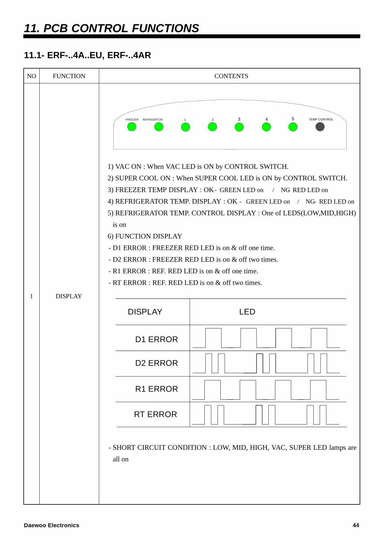
1) VAC ON : When VAC LED is ON by CONTROL SWITCH.
2) SUPER COOL ON : When SUPER COOL LED is ON by CONTROL SWITCH.
3) FREEZER TEMP DISPLAY : OK- GREEN LED on / NG- RED LED on
4) REFRIGERATOR TEMP. DISPLAY : OK - GREEN LED on / NG- RED LED on
5) REFRIGERATOR TEMP. CONTROL DISPLAY : One of LEDS(LOW,MID,HIGH)
is on
6) FUNCTION DISPLAY
- D1 ERROR : FREEZER RED LED is on & off one time.
- D2 ERROR : FREEZER RED LED is on & off two times.
- R1 ERROR : REF. RED LED is on & off one time.
- RT ERROR : REF. RED LED is on & off two times.
DISPLAY -
D1 ERROR
D2 ERROR
R1 ERROR
LED -
RT ERROR
- SHORT CIRCUIT CONDITION : LOW, MID, HIGH, VAC, SUPER LED lamps are
all on
Daewoo Electronics 44
2
TEMPERATURE
ADJUSTMENT
&
CONTROL
1) TEMP. CONTROL BUTTON
TEMP. CONTROL : When TEMP CONTROL button is pressed, the led lamps
LOW, MID, HIGH, VAC, SUPER COOL, LOW will be on in sequence.
TEMP. will be set if the button doesn’t get pressed again for 5 seconds.
2FORCED DEFROST : will be start when this button pushed for over 5 seconds
continuously.
3SHORT CIRCUIT OPERATION : will be started and stopped when this button
pushed over 30 times.
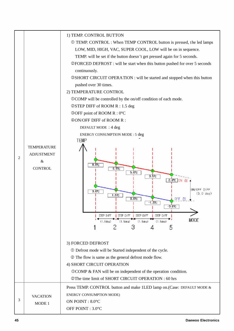
2) TEMPERATURE CONTROL
COMP will be controlled by the on/off condition of each mode.
2STEP DIFF of ROOM R : 1.5 deg
3OFF point of ROOM R : 0°C
4ON/OFF DIFF of ROOM R :
DEFAULT MODE : 4 deg
ENERGY CONSUMPTION MODE : 5 degTEMP
MODE
ON -
OFF -
11 3 4
STEP DIFF
ON/OFF DIFF (5.0 deg)
5.0-5.0-
0.0-0.0-
8.0-8.0-
3.0-3.0-
2.0-2.0-
-3.0--3.0-
1.5-1.5-
-1.5--1.5-
3.5-3.5-
6.5-6.5-
2 5
STEP DIFFSTEP DIFF STEP DIFF
(1.5deg) (1.5deg) (1.5deg) (1.5deg)
3) FORCED DEFROST
Defrost mode will be Started independent of the cycle.
2 The flow is same as the general defrost mode flow.
4) SHORT CIRCUIT OPERATION
COMP & FAN will be on independent of the operation condition.
2The time limit of SHORT CIRCUIT OPERATION : 60 hrs
3VACATION
MODE 1
Press TEMP. CONTROL button and make 1LED lamp on.(Case: DEFAULT MODE &
ENERGY CONSUMPTION MODE)
ON POINT : 8.0°C
OFF POINT : 3.0°C
45 Daewoo Electronics
4SUPER
MODE 5
Press TEMP. CONTROL button and make 5 led lamp on.
ON POINT : 2.0°C
OFF POINT : -3.0°C
5
FREEZER
OK / NG
DISPLAY
1) Initial Condition : FREEZER RED LED LAMP on
2) OK Condition : If temperature goes down under -5°C, green led lamp is supposed to
be on.
3) NG Condition : If temperature condition or time condition is satisfied, red led lamp
is on.
Temperature Condition : Over -5°C at D-SENSOR when Comp turns off.
Time Condition : Over -5°C at D SENSOR when Comp. Is running for 4hr.
4) D1 ERROR : FREEZER RED LED LAMP - on & off
(This error means that D-SENSOR is short or open condition.)
5) D2 ERROR : FREEZER RED LED LAMP - on & off two times
(D2 ERRORhappens when HEATER or TEMP. FUSE is open or there
is heavy frost on the surface of EVA. On this condition, the system
will be in defrost mode for 80 min.)
6
REFRIGERATOR
OK / NG
DISPLAY
1) Initial Condition : FREEZER RED LED LAMP on
2) OK Condition : If temperature goes down under 10°C, green led lamp is supposed to
be on.
3) NG Condition : If temperature condition or time condition is satisfied, red led lamp
is on.
Temperature Condition : Under -7°C or over 10°C at D-SENSOR when Comp
turns off.
Time Condition : Over 10°C at D SENSOR when Comp. Is running for 4hr.
4) R1 ERROR : REFRIGERATOR RED LED LAMP - on & off
(This error means that R-SENSOR is short or open condition.)
7
DETERMINATION
OF
DEFROST
1) Starting condition of Defrost Mode
When accumulated running time of comp. is 6, 8, 12, 30hrs.
2 After Checking the condition ‘’ if total time(COMP on time + COMP off time)
is more than 24, 48, 75hrs, then defrost mode starts immediately.
Accumulated running time of
COMP
Total running time of COMP
RT-SENSOR
Door Open Door Close Door Open Door Close
RT 33°C- 8HR 8HR 24HR 24HR
18<RT< 32°C 12HR 30HR 48HR 75HR
15<RT< 17°C 6HR 6HR 24HR 24HR
RT 14°C- 6HR 6HR 24HR 24HR
Daewoo Electronics 46
8
DEFROST
MODE
1) General Defrost Mode
Start : By determination of defrost
2 Process : general operation - Heater on - Pause - general operation
R-134A R-600A
TEMP. of Defrost return 10°C 16°C
PAUSE TIME 6min 7min
On D-sensor Error 30min 60min
Limit time 80min 80min
2) Forced Defrost Mode
Start : by press TEMP. CONTROL button for 5 seconds continuously.
2 Process : same as General Defrost Mode
General Defrost Mode is on for initial 30 seconds after heater is on. (for TEST)
9INITIAL
DEFROST
1) When power is on, if the temperature at the D-sensor is under 3.5°C, then General
Defrost Mode starts.
10
PREVENTION
OF COMP.
RESTART
1) RT ≤ 17 : The COMP can’t be on within 40 min after comp. is off even though
R-sensor is on condition. (This is to protect comp.) - FUNCTION of LOW RT
2) RT > 8 : The COMP can’t be on within 6 min after comp. is off even though
R-sensor is on condition. (This is to protect comp.)
11
ERROR
DISPLAY
&
CONTROL
1) D1 ERROR (It happens when D-SENSOR is OPEN or SHORT)
DISPLAY : FREEZER RED LED lamp in on & off one time.
2 CONTROL : Return to the limit defrost time of Defrost (30 min)
2) D2 ERROR (It happens when heater is off by time (80 min).
DISPLAY : FREEZER RED LED lamp in on & off two times.
2 CONTROL : Return to the limit defrost time of Defrost (80 min)
3) R1 ERROR (It happens when R-SENSOR is OPEN or SHORT)
DISPLAY : REFRIGERATOR RED LED lamp in on & off one time.
2 CONTROL : controlled by the condition of RT
RT-S TEMP ERROR 24- - 18- -
COMP. Operating rate(%) 40% 30% 44%
ON/OFF (min) 20 / 30 15 / 35 22 / 28
NOTE ERROR Low RT TEMP. General
3 CANCEL : when R-SENSOR is working normally.
4) RT ERROR (It happens when RT-SENSOR is OPEN or SHORT)
DISPLAY : REFRIGERATOR RED LED lamp in on & off two times.
2 CONTROL : The system is normally operating but the controlling by RT-
SENSOR doesn’t work.
3 CANCELATION : when RT -SENSOR is working normally.
47 Daewoo Electronics
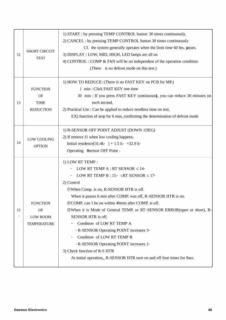
12SHORT CIRCUIT
TEST
1) START : by pressing TEMP CONTROL button 30 times continuously.
2) CANCEL : by pressing TEMP CONTROL button 30 times continuously
Cf. the system generally operates when the limit time 60 hrs. passes.
3) DISPLAY : LOW, MID, HIGH, LED lamps are all on
4) CONTROL : COMP & FAN will be on independent of the operation condition.
(There is no defrost mode on this test.)
13
FUNCTION
OF
TIME
REDUCTION
1) HOW TO REDUCE: (There is no FAST KEY on PCB for MP.)
1 min : Click FAST KEY one time
30 min : If you press FAST KEY continuously, you can reduce 30 minutes on
each second.
2) Practical Use : Can be applied to reduce needless time on test.
EX) function of stop for 6 min, confirming the determination of defrost mode
14LOW COOLING
OPTION
1) R-SENSOR OFF POINT ADJUST (DOWN 1DEG)
2) If remove J1 when low cooling happens.
Initial residence[31.4k- ] + 1.5 k- =32.9 k-
Operating R-sensor OFF Point -
15
`
FUNCTION
OF
LOW ROOM
TEMPERATURE
1) LOW RT TEMP :
- LOW RT TEMP A : RT SENSOR ≤ 14-
- LOW RT TEMP B : 15- ≤RT SENSOR ≤ 17-
2) Control
When Comp. is on, R-SENSOR HTR is off.
When it passes 6 min after COMP. was off, R-SENSOR HTR is on.
2COMP. can’t be on within 40min after COMP. is off.
3When it is Mode of General TEMP. or RT -SENSOR ERROR(open or short), R-
SENSOR HTR is off.
- Condition of LOW RT TEMP A
- R-SENSOR Operating POINT increases 3-
- Condition of LOW RT TEMP B
- R-SENSOR Operating POINT increases 1-
3) Check function of R-S HTR
At initial operation,, R-SENSOR HTR turn on and off four times for 8sec.
Daewoo Electronics 48
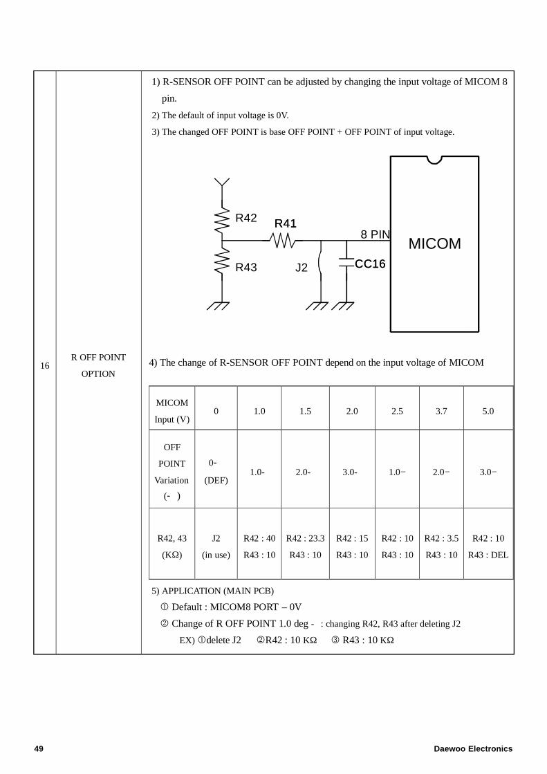
16R OFF POINT
OPTION
1) R-SENSOR OFF POINT can be adjusted by changing the input voltage of MICOM 8
pin.
2) The default of input voltage is 0V.
3) The changed OFF POINT is base OFF POINT + OFF POINT of input voltage.
MICOM
R42
R43 J2
8 PINR41R41
CC16CC16
4) The change of R-SENSOR OFF POINT depend on the input voltage of MICOM
5) APPLICATION (MAIN PCB)
Default : MICOM8 PORT – 0V
2 Change of R OFF POINT 1.0 deg - : changing R42, R43 after deleting J2
EX)delete J2 2R42 : 10 KΩ 3 R43 : 10 KΩ
MICOM
Input (V)0 1.0 1.5 2.0 2.5 3.7 5.0
OFF
POINT
Variation
(- )
0-
(DEF)1.0- 2.0- 3.0- 1.0− 2.0− 3.0−
R42, 43
(KΩ)
J2
(in use)
R42 : 40
R43 : 10
R42 : 23.3
R43 : 10
R42 : 15
R43 : 10
R42 : 10
R43 : 10
R42 : 3.5
R43 : 10
R42 : 10
R43 : DEL
49 Daewoo Electronics
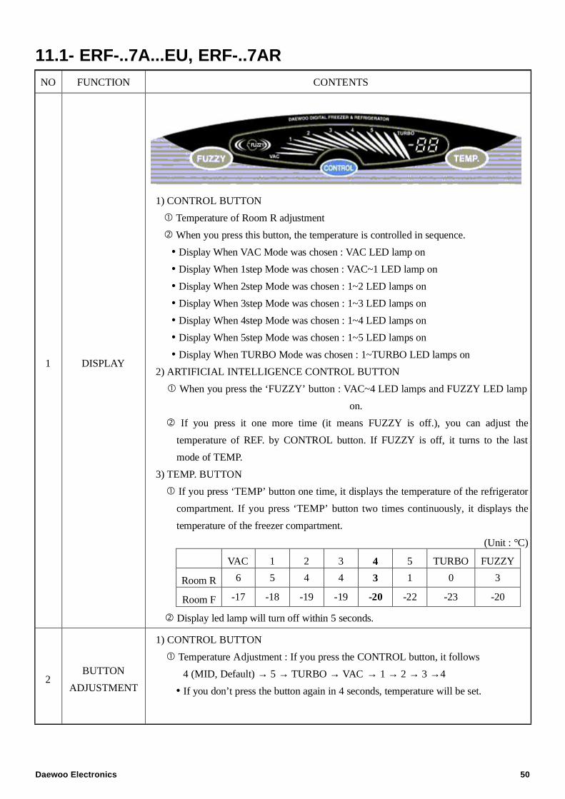
11.1- ERF-..7A...EU, ERF-..7ARNO FUNCTION CONTENTS
1 DISPLAY
1) CONTROL BUTTON
Temperature of Room R adjustment
When you press this button, the temperature is controlled in sequence.
Display When VAC Mode was chosen : VAC LED lamp on
Display When 1step Mode was chosen : VAC~1 LED lamp on
Display When 2step Mode was chosen : 1~2 LED lamps on
Display When 3step Mode was chosen : 1~3 LED lamps on
Display When 4step Mode was chosen : 1~4 LED lamps on
Display When 5step Mode was chosen : 1~5 LED lamps on
Display When TURBO Mode was chosen : 1~TURBO LED lamps on
2) ARTIFICIAL INTELLIGENCE CONTROL BUTTON
When you press the ‘FUZZY’ button : VAC~4 LED lamps and FUZZY LED lamp
on.
If you press it one more time (it means FUZZY is off.), you can adjust the
temperature of REF. by CONTROL button. If FUZZY is off, it turns to the last
mode of TEMP.
3) TEMP. BUTTON
If you press ‘TEMP’ button one time, it displays the temperature of the refrigerator
compartment. If you press ‘TEMP’ button two times continuously, it displays the
temperature of the freezer compartment.
(Unit : °C)
VAC 1 2 3 4 5 TURBO FUZZY
Room R 6 5 4 4 3 1 0 3
Room F -17 -18 -19 -19 -20 -22 -23 -20
Display led lamp will turn off within 5 seconds.
2BUTTON
ADJUSTMENT
1) CONTROL BUTTON
Temperature Adjustment : If you press the CONTROL button, it follows
4 (MID, Default) → 5 → TURBO → VAC → 1 → 2 → 3 →4
If you don’t press the button again in 4 seconds, temperature will be set.
Daewoo Electronics 50
2BUTTON
ADJUSTMENT
Forced Defrost Mode : Start by pressing CONTROL button for 5 seconds
continuously.
SHORT CIRCUIT TEST : start and cancel by pressing CONTROL button 30 times
continuously.
2) FUZZY BUTTON
Press the FUZZY button to turn on & off.
3) TEMP. BUTTON
If you press ‘TEMP’ button one time, it displays the temperature of Room R. If you
press ‘TEMP’ button two times continuously, it displays the temperature of Room
F.
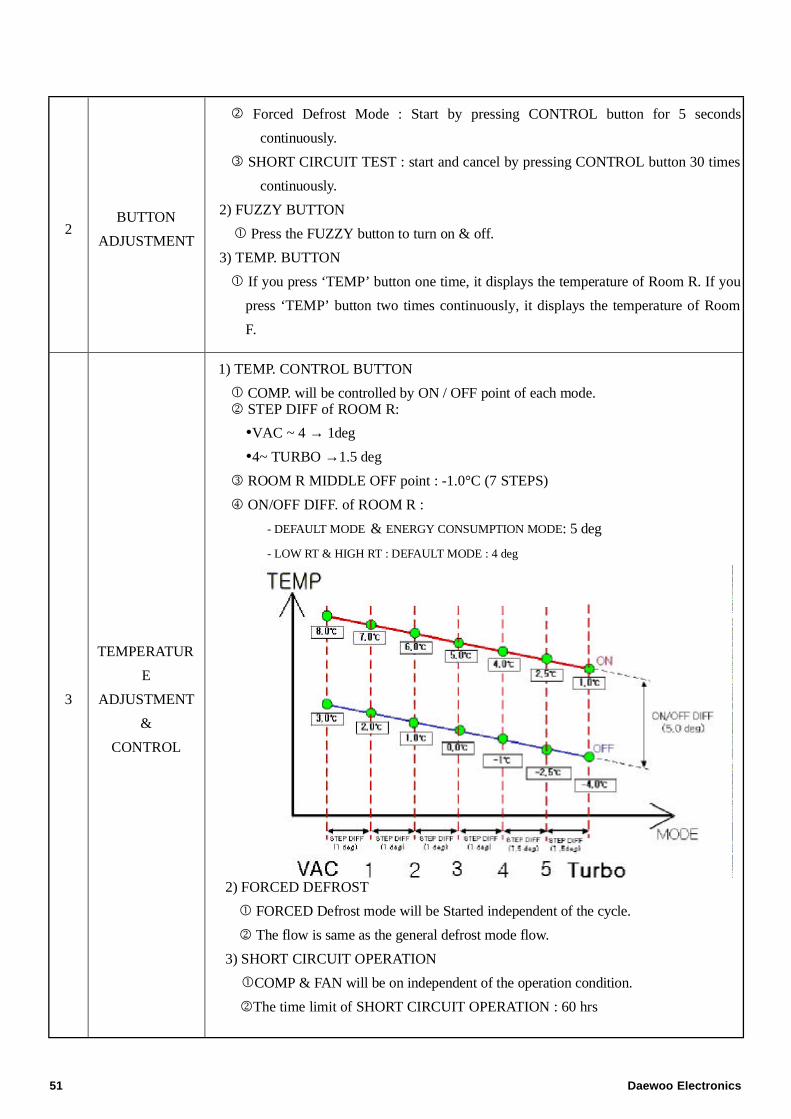
3
TEMPERATUR
E
ADJUSTMENT
&
CONTROL
1) TEMP. CONTROL BUTTON
COMP. will be controlled by ON / OFF point of each mode.2 STEP DIFF of ROOM R:
VAC ~ 4 → 1deg
4~ TURBO →1.5 deg
3 ROOM R MIDDLE OFF point : -1.0°C (7 STEPS)
4 ON/OFF DIFF. of ROOM R :
- DEFAULT MODE & ENERGY CONSUMPTION MODE: 5 deg
- LOW RT & HIGH RT : DEFAULT MODE : 4 deg
2) FORCED DEFROST
FORCED Defrost mode will be Started independent of the cycle.
2 The flow is same as the general defrost mode flow.
3) SHORT CIRCUIT OPERATION
COMP & FAN will be on independent of the operation condition.
2The time limit of SHORT CIRCUIT OPERATION : 60 hrs
51 Daewoo Electronics
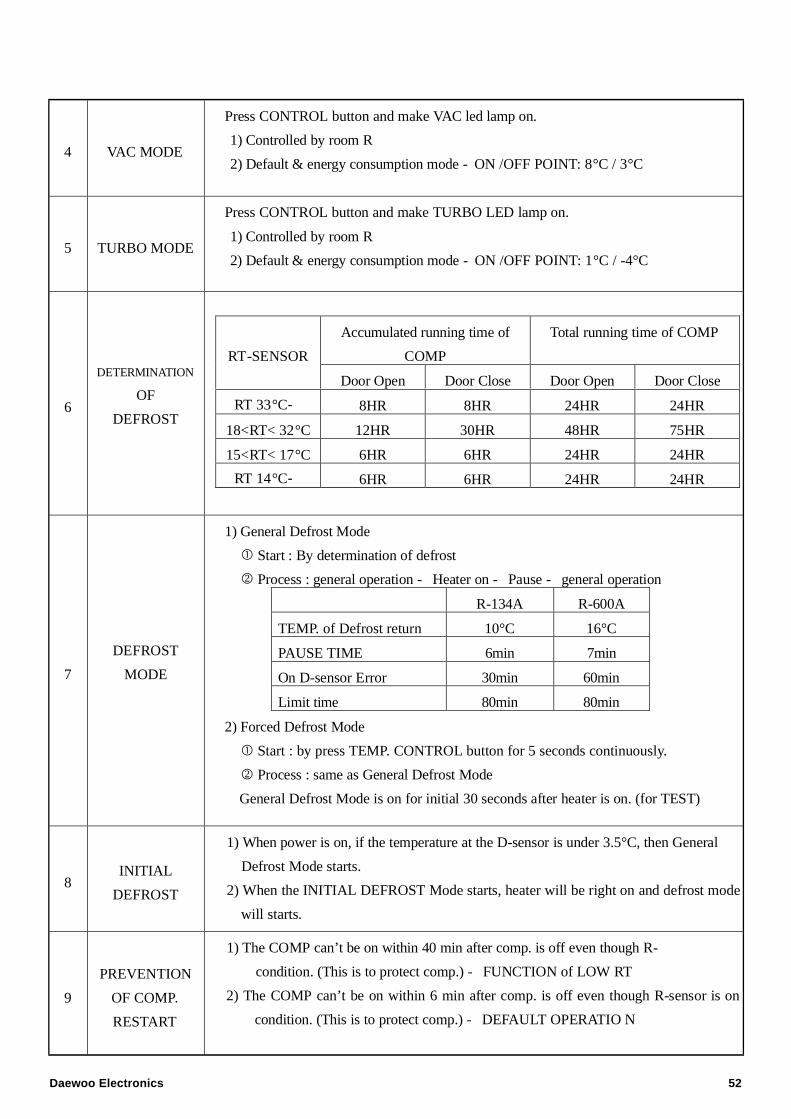
4 VAC MODE
Press CONTROL button and make VAC led lamp on.
1) Controlled by room R
2) Default & energy consumption mode - ON /OFF POINT: 8°C / 3°C
5 TURBO MODE
Press CONTROL button and make TURBO LED lamp on.
1) Controlled by room R
2) Default & energy consumption mode - ON /OFF POINT: 1°C / -4°C
6
DETERMINATION
OF
DEFROST
Accumulated running time of
COMP
Total running time of COMP
RT-SENSOR
Door Open Door Close Door Open Door Close
RT 33°C- 8HR 8HR 24HR 24HR
18<RT< 32°C 12HR 30HR 48HR 75HR
15<RT< 17°C 6HR 6HR 24HR 24HR
RT 14°C- 6HR 6HR 24HR 24HR
7
DEFROST
MODE
1) General Defrost Mode
Start : By determination of defrost
2 Process : general operation - Heater on - Pause - general operation
R-134A R-600A
TEMP. of Defrost return 10°C 16°C
PAUSE TIME 6min 7min
On D-sensor Error 30min 60min
Limit time 80min 80min
2) Forced Defrost Mode
Start : by press TEMP. CONTROL button for 5 seconds continuously.
2 Process : same as General Defrost Mode
General Defrost Mode is on for initial 30 seconds after heater is on. (for TEST)
8INITIAL
DEFROST
1) When power is on, if the temperature at the D-sensor is under 3.5°C, then General
Defrost Mode starts.
2) When the INITIAL DEFROST Mode starts, heater will be right on and defrost mode
will starts.
9
PREVENTION
OF COMP.
RESTART
1) The COMP can’t be on within 40 min after comp. is off even though R-
condition. (This is to protect comp.) - FUNCTION of LOW RT
2) The COMP can’t be on within 6 min after comp. is off even though R-sensor is on
condition. (This is to protect comp.) - DEFAULT OPERATIO N
Daewoo Electronics 52
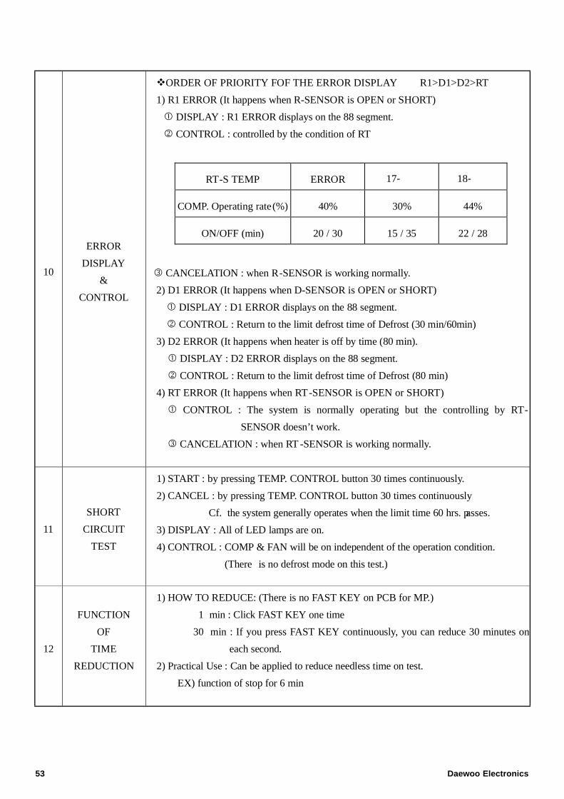
10
ERROR
DISPLAY
&
CONTROL
vORDER OF PRIORITY FOF THE ERROR DISPLAY R1>D1>D2>RT
1) R1 ERROR (It happens when R-SENSOR is OPEN or SHORT)
DISPLAY : R1 ERROR displays on the 88 segment.
2 CONTROL : controlled by the condition of RT
3 CANCELATION : when R-SENSOR is working normally.
2) D1 ERROR (It happens when D-SENSOR is OPEN or SHORT)
DISPLAY : D1 ERROR displays on the 88 segment.
2 CONTROL : Return to the limit defrost time of Defrost (30 min/60min)
3) D2 ERROR (It happens when heater is off by time (80 min).
DISPLAY : D2 ERROR displays on the 88 segment.
2 CONTROL : Return to the limit defrost time of Defrost (80 min)
4) RT ERROR (It happens when RT-SENSOR is OPEN or SHORT)
CONTROL : The system is normally operating but the controlling by RT-
SENSOR doesn’t work.
3 CANCELATION : when RT -SENSOR is working normally.
RT-S TEMP ERROR 17- 18-
COMP. Operating rate(%) 40% 30% 44%
ON/OFF (min) 20 / 30 15 / 35 22 / 28
11
SHORT
CIRCUIT
TEST
1) START : by pressing TEMP. CONTROL button 30 times continuously.
2) CANCEL : by pressing TEMP. CONTROL button 30 times continuously
Cf. the system generally operates when the limit time 60 hrs. passes.
3) DISPLAY : All of LED lamps are on.
4) CONTROL : COMP & FAN will be on independent of the operation condition.
(There is no defrost mode on this test.)
12
FUNCTION
OF
TIME
REDUCTION
1) HOW TO REDUCE: (There is no FAST KEY on PCB for MP.)
1 min : Click FAST KEY one time
30 min : If you press FAST KEY continuously, you can reduce 30 minutes on
each second.
2) Practical Use : Can be applied to reduce needless time on test.
EX) function of stop for 6 min
53 Daewoo Electronics
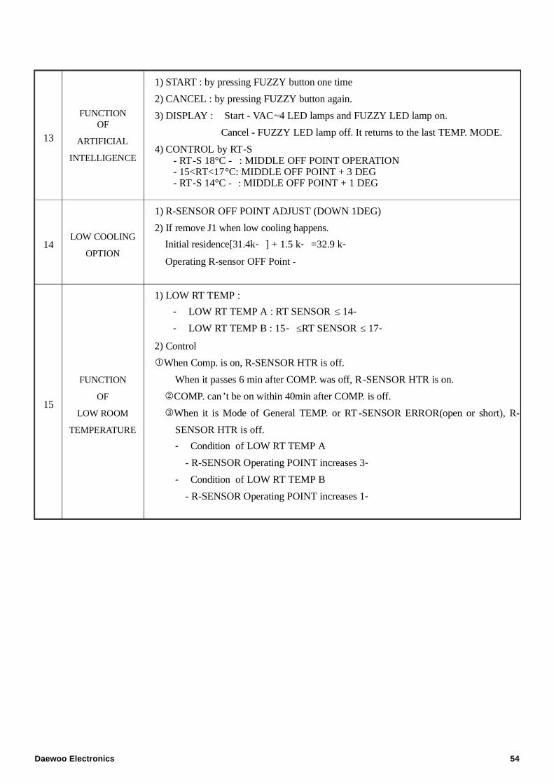
13
FUNCTIONOF
ARTIFICIAL
INTELLIGENCE
1) START : by pressing FUZZY button one time
2) CANCEL : by pressing FUZZY button again.
3) DISPLAY : Start - VAC~4 LED lamps and FUZZY LED lamp on.
Cancel - FUZZY LED lamp off. It returns to the last TEMP. MODE.
4) CONTROL by RT-S- RT-S 18°C - : MIDDLE OFF POINT OPERATION- 15<RT<17°C: MIDDLE OFF POINT + 3 DEG- RT-S 14°C - : MIDDLE OFF POINT + 1 DEG
14LOW COOLING
OPTION
1) R-SENSOR OFF POINT ADJUST (DOWN 1DEG)
2) If remove J1 when low cooling happens.
Initial residence[31.4k- ] + 1.5 k- =32.9 k-
Operating R-sensor OFF Point -
15
FUNCTION
OF
LOW ROOM
TEMPERATURE
1) LOW RT TEMP :
- LOW RT TEMP A : RT SENSOR ≤ 14-
- LOW RT TEMP B : 15- ≤RT SENSOR ≤ 17-
2) Control
When Comp. is on, R-SENSOR HTR is off.
When it passes 6 min after COMP. was off, R-SENSOR HTR is on.
2COMP. can’t be on within 40min after COMP. is off.
3When it is Mode of General TEMP. or RT -SENSOR ERROR(open or short), R-
SENSOR HTR is off.
- Condition of LOW RT TEMP A
- R-SENSOR Operating POINT increases 3-
- Condition of LOW RT TEMP B
- R-SENSOR Operating POINT increases 1-
Daewoo Electronics 54
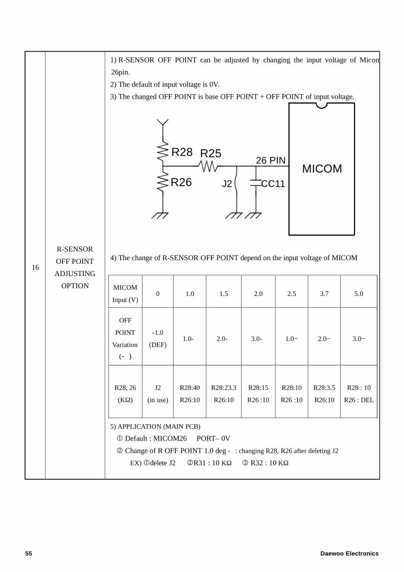
16
R-SENSOR
OFF POINT
ADJUSTING
OPTION
1) R-SENSOR OFF POINT can be adjusted by changing the input voltage of Micom
26pin.
2) The default of input voltage is 0V.
3) The changed OFF POINT is base OFF POINT + OFF POINT of input voltage.
MICOMR28
R26
26 PINR25
CC11J2
4) The change of R-SENSOR OFF POINT depend on the input voltage of MICOM
5) APPLICATION (MAIN PCB)
Default : MICOM26 PORT– 0V
2 Change of R OFF POINT 1.0 deg - : changing R28, R26 after deleting J2
EX)delete J2 2R31 : 10 KΩ 3 R32 : 10 KΩ
MICOM
Input (V)0 1.0 1.5 2.0 2.5 3.7 5.0
OFF
POINT
Variation
(- )
-1.0
(DEF)1.0- 2.0- 3.0- 1.0− 2.0− 3.0−
R28, 26
(KΩ)
J2
(in use)
R28:40
R26:10
R28:23.3
R26:10
R28:15
R26 :10
R28:10
R26 :10
R28:3.5
R26:10
R28 : 10
R26 : DEL
55 Daewoo Electronics

Daewoo Electronics Manufacturing España s.aPoligono industrial JundizC/Zurrupitieta nº27 01015
Vitoria-GasteizSpain