service manual e-studio 455
TRANSCRIPT

8/9/2019 Service manual E-studio 455
http://slidepdf.com/reader/full/service-manual-e-studio-455 1/670
SERVICE HANDBOOK MULTIFUNCTIONAL DIGITAL SYSTEMS
e-STUDIO205L/255/305
e-STUDIO355/455
Model: DP-2090/2520/3000/3570/4570Publish Date: April 2009File No. SHE090001A0
R090121H2200-TTECVer01_2009-06

8/9/2019 Service manual E-studio 455
http://slidepdf.com/reader/full/service-manual-e-studio-455 2/670
Trademarks
• The official name of Windows 95 is Microsoft Windows 95 Operating System.
• The official name of Windows 98 is Microsoft Windows 98 Operating System.
• The official name of Windows Me is Microsoft Windows Millennium Edition Operating System.
• The official name of Windows 2000 is Microsoft Windows 2000 Operating System.
• The official name of Windows XP is Microsoft Windows XP Operating System.
• Microsoft, Windows, Windows NT, Windows Vista and the brand names and product names of otherMicrosoft products are trademarks or registered trademarks of Microsoft Corporation in the U.S.
and/or other countries.
• Apple, AppleTalk, Macintosh, and Mac are trademarks of Apple Computer, Inc. in the U.S. and other
countries.
• PostScript is a trademark of Adobe Systems Incorporated.
• NOVELL, NetWare, and NDS are trademarks or registered trademarks of Novell, Inc.
• FLOIL is a registrated treadmark of Kanto Kasei Ltd. CORPORATION
• Mylar is a registered trademark of DuPont Teijin Films U.S. Limited Partnership.
• Molykote is a registered trademark of Dow Corning Corporation.
• iCLASS is a trademark of HID Corporation.
• MIFARE is a trademark of Royal Philips Electronics.
• Other company names and product names in this manual are the trademarks of their respectivecompanies.
© 2009 TOSHIBA TEC CORPORATION All rights reserved
Under the copyright laws, this manual cannot be reproduced in any form without prior written permission
of TOSHIBA TEC CORPORATION. No patent liability is assumed, however, with respect to the use of the
information contained herein.

8/9/2019 Service manual E-studio 455
http://slidepdf.com/reader/full/service-manual-e-studio-455 3/670
GENERAL PRECAUTIONS REGARDING THE SERVICE FOR
e-STUDIO205L/255/305/355/455
The installation and service should be done by a qualified servicetechnician.
1) Transportation/Installation- When transporting/installing the equipment, employ two persons and be sure to hold the posi-
tions as shown in the figure.
The equipment is quite heavy, and e-STUDIO205L/255/305 weighs approximately 57 kg (125.66
lb.), and e-STUDIO355/455 weighs approximately 60 kg (132.28 lb.), therefore pay full attention
when handling it.
- Be sure not to hold the movable parts or units (e.g. the control panel, ADU or RADF) when trans-
porting the equipment.
- Be sure to use a dedicated outlet with AC 110 V / 13.2 A, 115 V or 127 V / 12 A, 220-240 V or 240
V / 8 A for its power source.
- The equipment must be grounded for safety.- Select a suitable place for installation. Avoid excessive heat, high humidity, dust, vibration and
direct sunlight.
- Provide proper ventilation since the equipment emits a slight amount of ozone.
- To insure adequate working space for the copying operation, keep a minimum clearance of 80
cm (32”) on the left, 80 cm (32”) on the right and 10 cm (4”) on the rear.
- The equipment shall be installed near the socket outlet and shall be accessible.
- Be sure to fix and plug in the power cable securely after the installation so that no one trips over
it.
- When the equipment is used after the option is removed, be sure to install the parts or the covers
which have been taken off so that the inside of the equipment is not exposed.

8/9/2019 Service manual E-studio 455
http://slidepdf.com/reader/full/service-manual-e-studio-455 4/670
2) General Precautions at Service
- Be sure to turn the power OFF and unplug the power cable during service (except for the service
should be done with the power turned ON).
- Unplug the power cable and clean the area around the prongs of the plug and socket outlet once
a year or more. A fire may occur when dust lies on this area.
- When the parts are disassembled, reassembly is the reverse of disassembly unless otherwise
noted in this manual or other related documents. Be careful not to install small parts such as
screws, washers, pins, E-rings, star washers in the wrong places.- Basically, the equipment should not be operated with any parts removed or disassembled.
- The PC board must be stored in an anti-electrostatic bag and handled carefully using a wristband
since the ICs on it may be damaged due to static electricity.
- Avoid expose to laser beam during service. This equipment uses a laser diode. Be sure not to
expose your eyes to the laser beam. Do not insert reflecting parts or tools such as a screwdriver
on the laser beam path. Remove all reflecting metals such as watches, rings, etc. before starting
service.
- Be sure not to touch high-temperature sections such as the exposure lamp, fuser unit, damp
heater and areas around them.- Be sure not to touch high-voltage sections such as the chargers, transfer roller, developer, high-
voltage transformer, exposure lamp control inverter, inverter for the LCD backlight and power
supply unit. Especially, the board of these components should not be touched since the electric
charge may remain in the capacitors, etc. on them even after the power is turned OFF.
- Make sure that the equipment will not operate before touching potentially dangerous places (e.g.
rotating/operating sections such as gears, belts pulleys, fans and laser beam exit of the laser
optical unit).
- Be careful when removing the covers since there might be the parts with very sharp edges
underneath.
- When servicing the equipment with the power turned ON, be sure not to touch live sections and
rotating/operating sections. Avoid exposing your eyes to laser beam.
- Use designated jigs and tools.
- Use recommended measuring instruments or equivalents.
- Return the equipment to the original state and check the operation when the service is finished.
- Be very careful to treat the touch panel gently and never hit it. Breaking the surface could cause
malfunctions.
3) Important Service Parts for Safety
- The breaker, door switch, fuse, thermostat, thermofuse, thermistor, IC-RAMs including lithium
batteries, etc. are particularly important for safety. Be sure to handle/install them properly. If
these parts are short-circuited and their functions become ineffective, they may result in fatal
accidents such as burnout. Do not allow a short-circuit or do not use the parts not recommended
by Toshiba TEC Corporation.
4) Cautionary Labels- During servicing, be sure to check the rating plate and cautionary labels such as “Unplug the
power cable during service”, “CAUTION. HOT”, “CAUTION. HIGH VOLTAGE”, “CAUTION.
LASER BEAM”, etc. to see if there is any dirt on their surface and if they are properly stuck to the
equipment.
Caution: Before using the wristband, unplug the power cable of the equipment and
make sure that there are no charged objects which are not insulated in the
vicinity.

8/9/2019 Service manual E-studio 455
http://slidepdf.com/reader/full/service-manual-e-studio-455 5/670
5) Disposal of the Equipment, Supplies, Packing Materials, Used Batteries and IC-RAMs
- Regarding the recovery and disposal of the equipment, supplies, packing materials, used batter-
ies and IC-RAMs including lithium batteries, follow the relevant local regulations or rules.
Caution:Dispose of used batteries and IC-RAMs including lithium batteries according to this manual.
Attention:
Se débarrasser de batteries et IC-RAMs usés y compris les batteries en lithium selon ce manuel.Vorsicht:Entsorgung der gebrauchten Batterien und IC-RAMs (inclusive der Lithium-Batterie) nach diesem Handbuch.

8/9/2019 Service manual E-studio 455
http://slidepdf.com/reader/full/service-manual-e-studio-455 6/670

8/9/2019 Service manual E-studio 455
http://slidepdf.com/reader/full/service-manual-e-studio-455 7/670
ALLEGEMEINE SICHERHEITSMASSNAHMEN IN BEZUGAUF DIE WARTUNG FÜR e-STUDIO205L/255/305/355/455
Die Installation und die Wartung sind von einem qualifizierten Service-Techniker durchzuführen.
1. Transport/Installation- Zum Transportieren/Installieren des Gerätes werden 2 Personen benötigt. Nur an den in der
Abbildung gezeigten Stellen tragen.
Das Gerät ist sehr schwer und wiegt etwa 57 kg (e-STUDIO205L/255/305) oder 60 kg (e-
STUDIO355/455); deshalb muss bei der Handhabung des Geräts besonders aufgepasst wer-
den.
- Beim Transportieren des Geräts nicht an den beweglichen Teilen oder Einheiten (z.B. das Bedie-
nungsfeld, die Duplexeinheit oder die automatische Dokumentenzuführung) halten.
- Eine spezielle Steckdose mit Stromversorgung von AC 110 V / 13.2 A, 115 V oder 127 V / 12 A,
220-240 V / 8 A als Stromquelle verwenden.
- Das Gerät ist aus Sicherheitsgründen zu erden.- Einen geeigneten Standort für die Installation wählen. Standorte mit zuviel Hitze, hoher Luft-
feuchtigkeit, Staub, Vibrieren und direkter Sonneneinstrahlung sind zu vermeiden.
- Für ausreichende Belüftung sorgen, da das Gerät etwas Ozon abgibt.
- Um einen optimalen Kopierbetrieb zu gewährleisten, muss ein Abstand von mindestens 80 cm
links, 80 cm rechts und 10 cm dahinter eingehalten werden.
- Das Gerät ist in der Nähe der Steckdose zu installieren; diese muss leicht zu erreichen sein.
- Nach der Installation muss das Netzkabel richtig hineingesteckt und befestigt werden, damit nie-
mand darüber stolpern kann.
- Falls der Auspackungsstandort und der Installationsstandort des Geräts verschieden sind, die
Bildqualitätsjustierung (automatische Gammajustierung) je nach der Temperatur und Luft-
feuchtigkeit des Installationsstandorts und der Papiersorte, die verwendet wird, durchführen.

8/9/2019 Service manual E-studio 455
http://slidepdf.com/reader/full/service-manual-e-studio-455 8/670
2) Allgemeine Sicherheitsmassnahmen in bezug auf die Wartung
- Während der Wartung das Gerät ausschalten und das Netzkabel herausziehen (ausser Wartung,
die bei einem eingeschalteten Gerät, durchgeführt werden muss).
- Das Netzkabel herausziehen und den Bereich um die Steckerpole und die Steckdose die Umge-
bung in der Nähe von den Steckerzacken und der Steckdose wenigstens einmal im Jahr reini-
gen. Wenn Staub sich in dieser Gegend ansammelt, kann dies ein Feuer verursachen.
- Wenn die Teile auseinandergenommen werden, wenn nicht anders in diesem Handbuch usw
erklärt, ist das Zusammenbauen in umgekehrter Reihenfolge durchzuführen. Aufpassen, dasskleine Teile wie Schrauben, Dichtungsringe, Bolzen, E-Ringe, Stern-Dichtungsringe, Kabel-
bäume nicht an den verkehrten Stellen eingebaut werden.
- Grundsätzlich darf das Gerät mit enfernten oder auseinandergenommenen Teilen nicht in
Betrieb genommen werden.
- Das PC-Board muss in einer Anti-elektrostatischen Hülle gelagert werden. Nur Mit einer Man-
schette bei Betätigung eines Armbandes anfassen, sonst könnte es sein, dass die integrierten
Schaltkreise durch statische Elektrizität beschädigt werden.
- Setzen Sie sich während der Wartungsarbeiten nicht dem Laserstrahl aus. Dieses Gerät ist mit
einer Laserdiode ausgestattet. Es ist unbedingt zu vermeiden, direkt in den Laserstrahl zublicken. Keine reflektierenden Teile oder Werkzeuge, wie z. B. Schraubendreher, in den Pfad des
Laserstrahls halten. Vor den Wartungsarbeiten sämtliche reflektierenden Metallgegenstände, wie
Uhren, Ringe usw., entfernen.
- Auf keinen Fall Hochtemperaturbereiche, wie die Belichtungslampe, die Fixiereinheit, die
Heizquelle und die umliegenden Bereiche, berühren.
- Auf keinen Fall Hochspannungsbereiche, wie die Ladeeinheiten, das Transferband, die zweite
Transferwalze, die Entwicklereinheit, den Hochspannungstransformator, den Steuerumrichter für
die Belichtungslampe, den Umrichter für die LCD-Hintergrundbeleuchtung und das Netzgerät,
berühren. Insbesondere sollten die Platinen dieser Komponenten nicht berührt werden, da die
Kondensatoren usw. auch nach dem Ausschalten des Geräts noch elektrisch geladen sein kön-
nen.
- Vor dem Berühren potenziell gefährlicher Bereiche (z. B. drehbare oder betriebsrelevante Bere-
iche, wie Zahnräder, Riemen, Riemenscheiben, Lüfter und die Laseraustrittsöffnung der optis-chen Lasereinheit) sicherstellen, dass das Gerät sich nicht bedienen lässt.
- Beim Entfernen von Abdeckungen vorsichtig vorgehen, da sich darunter scharfkantige Kompo-
nenten befinden können.
- Bei Wartungsarbeiten am eingeschalteten Gerät dürfen keine unter Strom stehenden, drehbaren
oder betriebsrelevanten Bereiche berührt werden. Nicht direkt in den Laserstrahl blicken.
- Ausschließlich vorgesehene Werkzeuge und Hilfsmittel verwenden.
- Empfohlene oder gleichwertige Messgeräte verwenden.
- Nach Abschluss der Wartungsarbeiten das Gerät in den ursprünglichen Zustand zurück
versetzen und den einwandfreien Betrieb überprüfen.
- Das berührungsempfindliche Bedienungsfeld stets vorsichtig handhaben und keinen Stößen
aussetzen. Wenn die Oberfläche beschädigt wird, kann dies zu Funktionsstörungen führen.
3) Sicherheitsrelevante Wartungsteile
- Der Leistungsschutzschalter, der Türschalter, die Sicherung, der Thermostat, die Ther-
mosicherung, der Thermistor, die IC-RAMs einschließlich der Lithiumakkus usw. sind besonders
sicherheitsrelevant. Sie müssen unbedingt korrekt gehandhabt und installiert werden. Wenn
diese Teile kurzgeschlossen und funktionsunfähig werden, kann dies zu schwerwiegenden
Schäden, wie einem Abbrand, führen. Kurzschlüsse sind zu vermeiden, und es sind auss-
chließlich Teile zu verwenden, die von der Toshiba TEC Corporation empfohlen sind.
Vorsicht: Vor Benutzung der Manschette der Betätigung des Armbandes, das Netzkabeldes Gerätes herausziehen und prüfen, dass es in der Nähe keine geladenenGegenstände, die nicht isoliert sind, gibt.

8/9/2019 Service manual E-studio 455
http://slidepdf.com/reader/full/service-manual-e-studio-455 9/670
4) Warnetiketten
- Im Rahmen der Wartung unbedingt das Leistungsschild und die Etiketten mit Warnhinweisen
überprüfen [z. B. „Unplug the power cable during service“ („Netzkabel vor Beginn der Wartung-
sarbeiten abziehen“), „CAUTION. HOT“ („VORSICHT, HEISS“), „CAUTION. HIGH VOLTAGE“
(„VORSICHT, HOCHSPANNUNG“), „CAUTION. LASER BEAM“ („VORSICHT, LASER“) usw.],
um sicherzustellen, dass sie nicht verschmutzt sind und korrekt am Gerät angebracht sind.
5) Entsorgung des Geräts, der Verbrauchs- und Verpackungsmaterialien, alter Akkus und IC-RAMs- In Bezug auf die Entsorgung und Wiederverwertung des Geräts, der Verbrauchs- und Verpack-
ungsmaterialien, alter Akkus und IC-RAMs, einschließlich Lithiumakkus, sind die einschlägigen
nationalen oder regionalen Vorschriften zu befolgen.
Caution:Dispose of used batteries and IC-RAMs including lithium batteries according to this manual.
Attention:Se débarrasser de batteries et IC-RAMs usés y compris les batteries en lithium selon ce manuel.
Vorsicht:Entsorgung der gebrauchten Batterien und IC-RAMs (inclusive der Lithium-Batterie) nach diesem Handbuch.

8/9/2019 Service manual E-studio 455
http://slidepdf.com/reader/full/service-manual-e-studio-455 10/670

8/9/2019 Service manual E-studio 455
http://slidepdf.com/reader/full/service-manual-e-studio-455 11/670
© 2009 TOSHIBA TEC CORPORATION All rights reserved e-STUDIO205L/255/305/355/455CONTENTS
1
CONTENTS
1. SPECIFICATIONS / ACCESSORIES / OPTIONS / SUPPLIES ...................................1-11.1 Specifications ....................................................................................................................1-1
1.1.1 General .............................................................................................................. 1-1
1.1.2 Copy .................................................................................................................. 1-4
1.2 Accessories.......................................................................................................................1-8
1.3 Options.............................................................................................................................. 1-9
1.4 Supplies ..........................................................................................................................1-101.5 System List......................................................................................................................1-11
1.5.1 e-STUDIO205L/255/305 ..................................................................................1-11
1.5.2 e-STUDIO355/455 ...........................................................................................1-12
2. SELF-DIAGNOSIS MODES.......................................................................................... 2-12.1 Overview ...........................................................................................................................2-1
2.1.1 Control panel check mode (01)..........................................................................2-2
2.1.2 Test mode (03) ..................................................................................................2-2
2.1.3 Test print mode (04) ..........................................................................................2-2
2.1.4 Adjustment mode (05) ....................................................................................... 2-2
2.1.5 Setting mode (08) ..............................................................................................2-3
2.1.6 List print mode (9S) ...........................................................................................2-3
2.1.7 PM support mode (6S).......................................................................................2-32.1.8 EPU replacement mode (7S).............................................................................2-3
2.1.9 Firmware update mode (89)/(49) .......................................................................2-3
2.2 Input Check (Test Mode 03) .............................................................................................2-4
2.3 Output Check (Test Mode 03).........................................................................................2-12
2.4 Test Print Mode (Test Mode 04) .....................................................................................2-16
2.5 List Print Mode ................................................................................................................ 2-17
2.5.1 Operation procedure........................................................................................2-17
2.5.2 List printing ......................................................................................................2-19
2.6 Adjustment Mode (05) .................................................................................................... 2-29
2.6.1 Operation procedure........................................................................................2-29
2.6.2 Test print pattern in Adjustment Mode (05) ..................................................... 2-31
2.6.3 Adjustment codes ............................................................................................ 2-322.7 Setting Mode (08)............................................................................................................2-60
2.7.1 Operation procedure........................................................................................2-60
2.7.2 Setting codes ................................................................................................... 2-62
2.7.3 Pixel counter and its related code..................................................................2-187
2.7.4 PM support mode related code...................................................................... 2-200
2.8 Classification List of Adjustment Mode (05)/Setting Mode (08) .................................... 2-205
3. ADJUSTMENT .............................................................................................................. 3-13.1 Adjustment Order.............................................................................................................. 3-1
3.2 Adjustment of Auto-Toner Sensor.....................................................................................3-2
3.3 Image Dimensional Adjustment ........................................................................................ 3-4
3.3.1 General description............................................................................................ 3-4
3.3.2 Paper alignment at the registration roller........................................................... 3-63.3.3 Printer related adjustment..................................................................................3-8
3.3.4 Scanner related adjustment............................................................................. 3-14
3.4 Image Quality Adjustment (Copying Function)................................................................3-22
3.4.1 Automatic gamma adjustment .........................................................................3-22
3.4.2 Density adjustment .......................................................................................... 3-23
3.4.3 Background adjustment ................................................................................... 3-24
3.4.4 Sharpness adjustment .....................................................................................3-24
3.4.5 Setting range correction................................................................................... 3-25
3.4.6 Adjustment of smudged/faint text ....................................................................3-25
3.4.7 Gamma balance adjustment ...........................................................................3-26
3.4.8 Adjustment of image density............................................................................3-27

8/9/2019 Service manual E-studio 455
http://slidepdf.com/reader/full/service-manual-e-studio-455 12/670
e-STUDIO205L/255/305/355/455 © 2009 TOSHIBA TEC CORPORATION All rights reservedCONTENTS
2
3.4.9 Background offsetting adjustment for RADF ...................................................3-27
3.5 Image Quality Adjustment (Printing Function).................................................................3-28
3.5.1 Adjustment of smudged/faint text ....................................................................3-28
3.5.2 Adjustment of image density............................................................................3-29
3.5.3 Gamma balance adjustment............................................................................3-30
3.6 Image Quality Adjustment (Scanning Function)..............................................................3-31
3.6.1 Gamma balance adjustment............................................................................3-31
3.6.2 Density adjustment .......................................................................................... 3-32
3.6.3 Judgment threshold for ACS............................................................................ 3-33
3.6.4 Sharpness adjustment .....................................................................................3-333.6.5 Setting range correction................................................................................... 3-34
3.6.6 Background adjustment ...................................................................................3-35
3.6.7 Fine adjustment of black density .....................................................................3-36
3.6.8 RGB conversion method selection .................................................................. 3-36
3.6.9 Adjustment of saturation.................................................................................. 3-36
3.6.10 Background processing offset adjustment.......................................................3-37
3.7 Image Quality Adjustment (FAX Function)......................................................................3-38
3.7.1 Density adjustment .......................................................................................... 3-38
3.7.2 Adjustment of image density............................................................................3-39
3.8 Adjustment of High-Voltage Transformer........................................................................3-40
3.8.1 Adjustment....................................................................................................... 3-40
3.8.2 Precautions...................................................................................................... 3-463.9 Adjustment of the Scanner Section................................................................................. 3-48
3.9.1 Carriages .........................................................................................................3-48
3.9.2 Lens unit ..........................................................................................................3-52
3.10 Adjustment of the Paper Feeding System....................................................................... 3-55
3.10.1 Sheet sideways deviation caused by paper feeding........................................3-55
3.11 Adjustment of Developer Unit ......................................................................................... 3-58
3.11.1 Doctor-to-sleeve gap ....................................................................................... 3-58
3.12 Adjustment of the RADF .................................................................................................3-61
3.12.1 Adjustment of RADF position........................................................................... 3-61
3.12.2 Adjustment of RADF height .............................................................................3-66
3.12.3 Adjustment of skew.......................................................................................... 3-68
3.12.4 Adjustment of the leading edge position..........................................................3-71
3.12.5 Adjustment of horizontal position.....................................................................3-733.12.6 Adjustment of copy ratio ..................................................................................3-74
3.12.7 Adjustment of RADF opening/closing sensor .................................................. 3-75
3.13 Adjustment of the Finisher (MJ-1025).............................................................................3-76
3.13.1 Adjusting the folding position (Electrical system (Finisher/Saddle unit)) ......... 3-76
3.13.2 Adjusting the sensor output (Electrical system (Puncher unit; option)) ........... 3-77
3.13.3 Registering the number of punch hole
(Electrical system (Puncher unit; option)) ........................................................ 3-78
3.13.4 After replacing the EEPROM (IC1002)
(Electrical system (Puncher unit; option)) ........................................................ 3-79
3.14 Adjustment of the Finisher (MJ-1024).............................................................................3-80
3.14.1 Adjusting the alignment position (Finisher unit) ............................................... 3-80
3.14.2 Adjusting the staple position (Finisher unit) ..................................................... 3-813.14.3 Adjusting the folding position (Saddle stitcher unit) ......................................... 3-83
3.14.4 Fine adjustment of binding/folding position (Saddle stitcher unit)....................3-85
3.14.5 Sensor output adjustment (Puncher unit) ........................................................3-86
3.14.6 Registering the number of punch holes (Puncher unit) ...................................3-87
3.15 Adjustment of the Finisher (MJ-1101).............................................................................3-88
3.15.1 Adjusting the alignment position ...................................................................... 3-88
3.15.2 Adjusting the stapling position .........................................................................3-90
3.15.3 B4-size recycled paper mode settings.............................................................3-92
3.16 Adjustment of Dogleg......................................................................................................3-94
4. BACKUP FUNCTION....................................................................................................4-14.1 Data Cloning .....................................................................................................................4-1
8/9/2019 Service manual E-studio 455
http://slidepdf.com/reader/full/service-manual-e-studio-455 13/670
© 2009 TOSHIBA TEC CORPORATION All rights reserved e-STUDIO205L/255/305/355/455CONTENTS
3
4.1.1 General description............................................................................................ 4-1
4.1.2 Precautions........................................................................................................ 4-1
4.1.3 Backup files ....................................................................................................... 4-2
4.1.4 Cloning procedure ............................................................................................. 4-4
4.2 AES Data Encryption Function Setting ...........................................................................4-11
4.2.1 General description..........................................................................................4-11
4.2.2 Precautions...................................................................................................... 4-11
4.2.3 Setting procedure ............................................................................................ 4-11
4.2.4 Procedure for disabling data encryption function............................................. 4-15
4.2.5 Procedure for discarding HDD when data encryption function is enabled ......4-154.3 Assist Mode.....................................................................................................................4-16
4.3.1 Assist mode ..................................................................................................... 4-16
4.3.2 Operating procedure of assist mode................................................................4-17
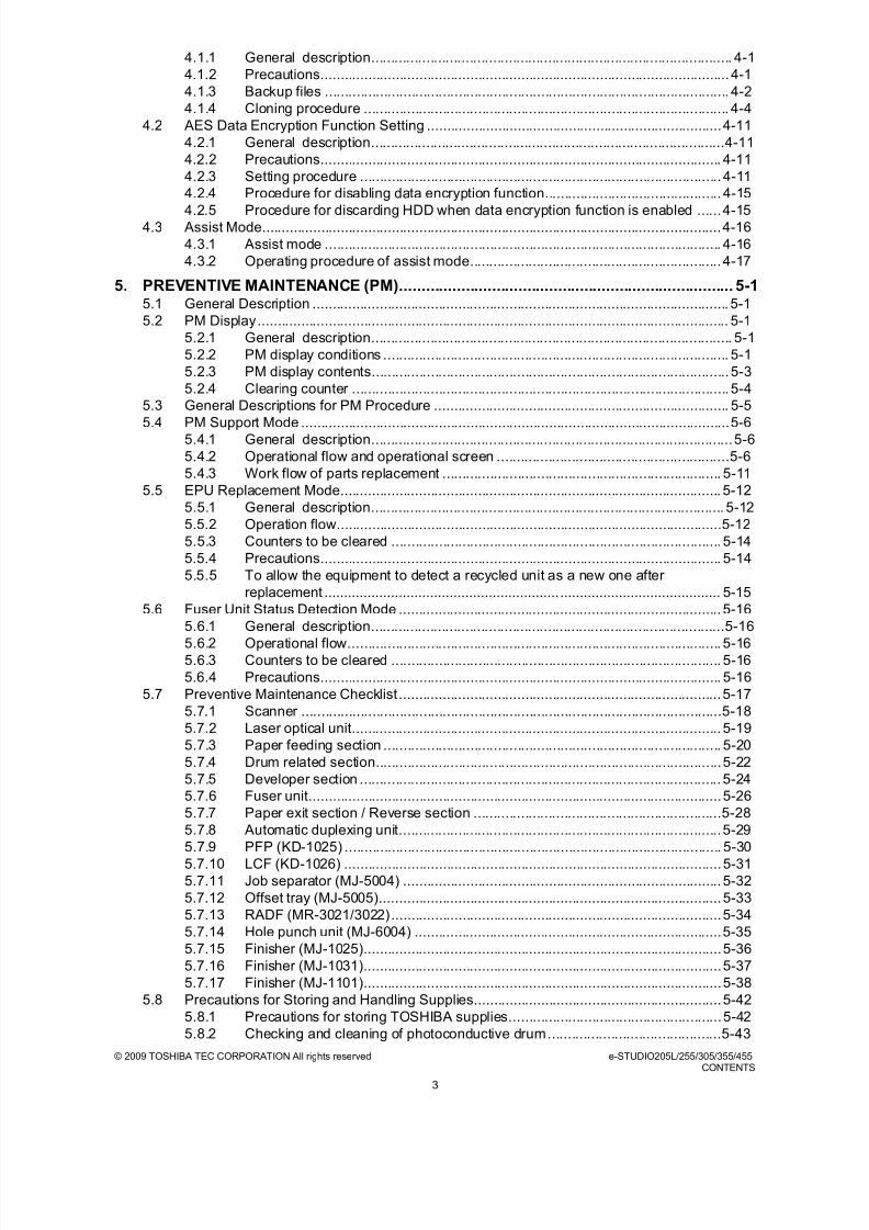
5. PREVENTIVE MAINTENANCE (PM)............................................................................ 5-15.1 General Description .......................................................................................................... 5-1
5.2 PM Display........................................................................................................................ 5-1
5.2.1 General description............................................................................................ 5-1
5.2.2 PM display conditions ........................................................................................ 5-1
5.2.3 PM display contents...........................................................................................5-3
5.2.4 Clearing counter ................................................................................................ 5-4
5.3 General Descriptions for PM Procedure ........................................................................... 5-5
5.4 PM Support Mode .............................................................................................................5-65.4.1 General description............................................................................................5-6
5.4.2 Operational flow and operational screen ...........................................................5-6
5.4.3 Work flow of parts replacement ....................................................................... 5-11
5.5 EPU Replacement Mode................................................................................................. 5-12
5.5.1 General description.......................................................................................... 5-12
5.5.2 Operation flow..................................................................................................5-12
5.5.3 Counters to be cleared .................................................................................... 5-14
5.5.4 Precautions...................................................................................................... 5-14
5.5.5 To allow the equipment to detect a recycled unit as a new one after
replacement ..................................................................................................... 5-15
5.6 Fuser Unit Status Detection Mode .................................................................................. 5-16
5.6.1 General description..........................................................................................5-165.6.2 Operational flow............................................................................................... 5-16
5.6.3 Counters to be cleared .................................................................................... 5-16
5.6.4 Precautions...................................................................................................... 5-16
5.7 Preventive Maintenance Checklist ..................................................................................5-17
5.7.1 Scanner ...........................................................................................................5-18
5.7.2 Laser optical unit.............................................................................................. 5-19
5.7.3 Paper feeding section ...................................................................................... 5-20
5.7.4 Drum related section........................................................................................5-22
5.7.5 Developer section ............................................................................................ 5-24
5.7.6 Fuser unit.........................................................................................................5-26
5.7.7 Paper exit section / Reverse section ...............................................................5-28
5.7.8 Automatic duplexing unit..................................................................................5-29
5.7.9 PFP (KD-1025) ................................................................................................ 5-30
5.7.10 LCF (KD-1026) ................................................................................................5-31
5.7.11 Job separator (MJ-5004) ................................................................................. 5-32
5.7.12 Offset tray (MJ-5005).......................................................................................5-33
5.7.13 RADF (MR-3021/3022)....................................................................................5-34
5.7.14 Hole punch unit (MJ-6004) ..............................................................................5-35
5.7.15 Finisher (MJ-1025)...........................................................................................5-36
5.7.16 Finisher (MJ-1031)...........................................................................................5-37
5.7.17 Finisher (MJ-1101)...........................................................................................5-38
5.8 Precautions for Storing and Handling Supplies...............................................................5-42
5.8.1 Precautions for storing TOSHIBA supplies......................................................5-42
5.8.2 Checking and cleaning of photoconductive drum............................................5-43

8/9/2019 Service manual E-studio 455
http://slidepdf.com/reader/full/service-manual-e-studio-455 14/670
e-STUDIO205L/255/305/355/455 © 2009 TOSHIBA TEC CORPORATION All rights reservedCONTENTS
4
5.8.3 Checking and cleaning of drum cleaning blade ...............................................5-44
5.8.4 Checking and cleaning of fuser roller and pressure roller ............................... 5-44
5.8.5 Checking and replacing the transfer roller ....................................................... 5-45
5.9 PM KIT ............................................................................................................................5-46
5.10 Maintenance Part List ..................................................................................................... 5-47
5.11 Grease List......................................................................................................................5-49
5.12 Operational Items in Overhauling....................................................................................5-49
6. ERROR CODE AND TROUBLESHOOTING ................................................................6-16.1 General Descriptions.........................................................................................................6-1
6.2 Error Code List..................................................................................................................6-2
6.2.1 Jam....................................................................................................................6-2
6.2.2 Service call ........................................................................................................ 6-8
6.2.3 Error in Internet FAX / Scanning Function.......................................................6-13
6.2.4 Printer function error ........................................................................................6-23
6.3 Diagnosis and Prescription for Each Error Code ............................................................ 6-26
6.3.1 Paper transport jam ......................................................................................... 6-26
6.3.2 Paper misfeeding.............................................................................................6-38
6.3.3 Cover open jam ...............................................................................................6-44
6.3.4 RADF jam ........................................................................................................ 6-48
6.3.5 Finisher jam .....................................................................................................6-50
6.3.6 Drive system related service call .....................................................................6-64
6.3.7 Paper feeding system related service call .......................................................6-656.3.8 Scanning system related service call............................................................... 6-69
6.3.9 Fuser unit related service call .......................................................................... 6-71
6.3.10 Communication related service call .................................................................6-74
6.3.11 RADF related service call ................................................................................ 6-76
6.3.12 Laser optical unit related service call...............................................................6-76
6.3.13 Finisher related service call .............................................................................6-77
6.3.14 Service call for others ....................................................................................6-101
6.3.15 Error in Internet FAX / Scanning Function .....................................................6-104
6.3.16 Printer function error ......................................................................................6-118
6.4 Troubleshooting for the Image ......................................................................................6-120
6.4.1 Abnormality of image density / Gray balance ................................................6-120
6.4.2 Background fogging....................................................................................... 6-1216.4.3 Moire/lack of sharpness.................................................................................6-122
6.4.4 Toner offset....................................................................................................6-123
6.4.5 Blurred image ................................................................................................6-124
6.4.6 Poor fusing.....................................................................................................6-125
6.4.7 Blank copy .....................................................................................................6-126
6.4.8 Solid copy ......................................................................................................6-127
6.4.9 White banding or white viod(in the feeding direction) ....................................6-128
6.4.10 White banding (at right angle with the feeding direction)...............................6-130
6.4.11 Skew (inclined image)....................................................................................6-131
6.4.12 Black banding (in the feeding direction).........................................................6-132
6.4.13 Black banding (at right angle with the feeding direction) ...............................6-133
6.4.14 White spots.................................................................................................... 6-134
6.4.15 Poor image transfer ....................................................................................... 6-135
6.4.16 Uneven image density ...................................................................................6-136
6.4.17 Faded image (low density, abnormal gray balance)......................................6-137
6.4.18 Image dislocation in feeding direction............................................................6-138
6.4.19 Jittering image ............................................................................................... 6-139
6.4.20 Poor cleaning................................................................................................. 6-140
6.4.21 Uneven light distribution ................................................................................ 6-141
6.4.22 Blotched image.............................................................................................. 6-142
7. REPLACEMANT OF HDD/PC BOARDS...................................................................... 7-17.1 Precautions and Procedures for Replacing PC Boards and HDD .................................... 7-1
7.1.1 Precautions when replacing PC boards.............................................................7-1

8/9/2019 Service manual E-studio 455
http://slidepdf.com/reader/full/service-manual-e-studio-455 15/670
© 2009 TOSHIBA TEC CORPORATION All rights reserved e-STUDIO205L/255/305/355/455CONTENTS
5
7.1.2 HDD fault diagnosis...........................................................................................7-2
7.1.3 Precautions and procedures when replacing the HDD......................................7-4
7.1.4 Precautions and Procedures when replacing the SYS board............................7-9
7.1.5 Procedures when replacing the LGC board.....................................................7-11
7.1.6 Procedures when replacing the SLG board ....................................................7-11
7.1.7 Precautions and Procedures when replacing SRAM board............................. 7-12
7.1.8 Procedures when replacing EEPROM.............................................................7-15
7.1.9 Firmware confirmation after the PC board/HDD replacement .........................7-15
7.2 Precautions for Installation of GP-1070 and Disposal of HDD/Board .............................7-16
7.2.1 Precautions for Installation of GP-1070 and Disposal of HDD/Board.............. 7-167.2.2 Precautions when disposing of the SYS board................................................7-16
7.2.3 Precautions when disposing of the SRAM board ............................................ 7-16
8. FIRMWARE UPDATING ............................................................................................... 8-18.1 Firmware Updating with USB Media ................................................................................. 8-5
8.1.1 Master data/System ROM/Engine ROM/Scanner ROM.................................... 8-7
8.2 Firmware Updating with PWA-DWNLD-350-JIG2........................................................... 8-16
8.2.1 Writing the data to the download jig (PWA-DWNLD-350-JIG2)....................... 8-17
8.2.2 System ROM ................................................................................................... 8-20
8.2.3 Engine ROM .................................................................................................... 8-22
8.3 Firmware Updating with K-PWA-DLM-320......................................................................8-24
8.3.1 Scanner ROM..................................................................................................8-25
8.3.2 RADF firmware (MR-3021/3022) .....................................................................8-278.3.3 Hole punch unit firmware (MJ-6101)................................................................8-29
8.3.4 Finisher firmware (MJ-1025)............................................................................ 8-33
8.3.5 Finisher firmware (MJ-1024)............................................................................ 8-35
8.3.6 Finisher firmware (MJ-1101)............................................................................ 8-38
8.3.7 Converter Firmware (MJ-1101)........................................................................ 8-40
8.3.8 Finisher firmware (MJ-1031)............................................................................ 8-44
8.3.9 Fax unit firmware (GD-1250) ...........................................................................8-47
8.4 Confirmation of the updated data.................................................................................... 8-50
8.5 When Firmware Updating Fails.......................................................................................8-51
8.5.1 Procedure ........................................................................................................8-51
8.5.2 Flow chart for correcting USB update failure ...................................................8-52
9. POWER SUPPLY UNIT ................................................................................................ 9-19.1 Construction......................................................................................................................9-1
9.2 Operation of DC Output Circuits .......................................................................................9-2
9.3 Output Channel .................................................................................................................9-4
9.4 Fuse .................................................................................................................................. 9-6
9.5 Configuration of Power Supply Unit .................................................................................. 9-7
9.6 Sequence of Power Supply............................................................................................... 9-8
9.7 AC Wire Harness ..............................................................................................................9-9
10. REMOTE SERVICE.....................................................................................................10-110.1 Auto Supply Order...........................................................................................................10-1
10.1.1 Outline .............................................................................................................10-1
10.1.2 Setting item......................................................................................................10-2
10.1.3 Setting procedure ............................................................................................10-4
10.1.4 Order sheet format.........................................................................................10-13
10.2 Service Notification .......................................................................................................10-15
10.2.1 Outline ........................................................................................................... 10-15
10.2.2 Setting............................................................................................................10-16
10.2.3 Items to be notified ........................................................................................ 10-24
11. WIRE HARNESS CONNECTION DIAGRAMS........................................................... 11-111.1 AC Wire Harness ............................................................................................................11-1
11.2 DC Wire Harness (e-STUDIO205L/255/305).......................................................... Appendix
11.3 Electric Parts Layout (e-STUDIO205L/255/305)..................................................... Appendix
11.4 DC Wire Harness (e-STUDIO355/455)................................................................... Appendix

8/9/2019 Service manual E-studio 455
http://slidepdf.com/reader/full/service-manual-e-studio-455 16/670
e-STUDIO205L/255/305/355/455 © 2009 TOSHIBA TEC CORPORATION All rights reservedCONTENTS
6
11.5 Electric Parts Layout (e-STUDIO355/455).............................................................. Appendix

8/9/2019 Service manual E-studio 455
http://slidepdf.com/reader/full/service-manual-e-studio-455 17/670
© 2009 TOSHIBA TEC CORPORATION All rights reserved e-STUDIO205L/255/305/355/455SPECIFICATIONS / ACCESSORIES / OPTIONS / SUPPLIES
1 - 1
1. SPECIFICATIONS / ACCESSORIES / OPTIONS / SUPPLIES
1.1 Specifications
1.1.1 General
Type......................................... Desktop type (console type: when paper feed pedestal (PFP) and large
capacity feeder (LCF) are installed)
Original glass........................... Fixed type (the left rear corner used as guide to place originals)
Copy process .......................... Indirect electrophotographic process (dry)
Fixing method.......................... External heating STF fusing system
Photosensor type ....................OPC
Original scanning sensor......... Linear CCD sensor
Scanning light source..............Xenon lamp
Reproduction ratio ................... Actual ratio: 100±0.5%
Zooming: 25 to 400% in increments of 1%
(25 to 200% when using RADF)
Resolution ............................... Scanning: 600 dpi x 600 dpiPrinting: Equivalent to 2400 dpi x 600 dpi
Gradation................................. 256 steps
Paper feeding.......................... 2 drawers + Bypass feeding + LCF (optional)
2 drawers + Bypass feeding + 2 PFP (optional)
Paper supply ...........................Standard drawers:
Stack height 60.5 mm, equivalent to 550 sheets; 80 g/m2 (22 lb.
Bond)): Depends on destinations or versions.
Bypass feeding:Stack height 11 mm: equivalent to 100 sheets; 80 g/m2 (22 lb.
Bond)
PFP:(Option):
Two drawer: stack height 60.5 mm, 550 sheets; 80 g/m2 (22 lb.
Bond)
LCF:(Option)
Stack height 110 mm x 2: equivalent to 1000 sheets; 80 g/m2 (22
lb. Bond)
Values in [[ ]] are for e-STUDIO205L, values in {{ }} are for e-STUDIO305, values in [ ] are for e-
STUDIO355, values in { } are for e-STUDIO455 and values in < > are for e-STUDIO355/455 in case
that the specification is different among e-STUDIO205L, e-STUDIO255, e-STUDIO305, e-STUDIO355 and e-STUDIO455.

8/9/2019 Service manual E-studio 455
http://slidepdf.com/reader/full/service-manual-e-studio-455 18/670
e-STUDIO205L/255/305/355/455 © 2009 TOSHIBA TEC CORPORATION All rights reservedSPECIFICATIONS / ACCESSORIES / OPTIONS / SUPPLIES
1 - 2
paper
Automatic duplexing unit ......... Stackless, Switchback type
e-STUDIO205L/255/305: No exclusive switchback mechanism
e-STUDIO355/455: Uses an exclusive switchback mechanism
Acceptable paper size
A3, A4, A4-R, A5-R, B4, B5, B5-R, FOLIO, 8K, 16K, 16K-R, LD,
LG, LT, LT-R, ST-R, COMPUTER, 13"LG, 8.5" x 8.5"
Acceptable paper weight
64 g/m2 to 105 g/m2 (17 lb. Bond to 28 lb. Cover)
Offset mechanism ................... e-STUDIO205L/255/305: No exclusive offset mechanism
e-STUDIO355/455: Uses an exclusive offset mechanism
Offsetting mechanism with movable exit roller
(Shift amount: 30 mm, Stack height: 40 mm (250 sheets))
Interface ..................................Standard:
USB 2.0 (High Speed),
Ethernet (10BASE-T/100BASE-TX)
Optional:Wireless LAN (IEEE 802.11b/g),
Bluetooth (HCRP and BIP)
Toner supply............................ Automatic toner density detection/supply
Toner cartridge replacing method (There is a recovered toner supply
mechanism.)
Toner density control ............... Automatic density mode and manual density mode selectable in 11
steps
Memory(RAM) ......................... Main memory: 1GB(Incl. page memory)
Paper size Drawers A3, A4, A4-R, A5-R, B4, B5, B5-R, FOLIO, 8K, 16K, 16K-R,LD, LG, LT, LT-R, ST-R, COMPUTER, 13"LG, 8.5"x8.5"(Non-standard sizes are not available)
Bypass feeding A3, A4, A4-R, A5-R, B4, B5, B5-R, FOLIO, 8K, 16K, 16K-R,LD, LG, LT, LT-R, ST-R, COMPUTER, 13"LG, 8.5"x8.5"
LCF (optional) A4, LT(Non-standard sizes are not available)
Paper type Drawers/LCF (optional) Plain paper (Tracing paper, OHP films, sticker labels, envelopes andpunched paper are not available)
Bypass feeding Plain paper, Tracing paper, OHP film, Sticker labels, Tab paper
Paper weight Drawers/LCF (optional) 64 g/m2 to 105 g/m2 (17 lb. Bond to 28 lb. Cover)
Bypass feeding 52g/m2 to 209 g/m2 (14 lb. Bond to 110 lb. Cover)
Plain paper: 64g/m2 to 80 g/m2 (17 lb. Bond to 21 lb. Cover)
Thin paper: 52g/m2 to 63 g/m2 (14 lb. Bond to 17 lb. Cover)
Thick 1: 81g/m2 to 105 g/m2 (21.5 lb. Bond to 28 lb. Cover)
Thick 2: 106g/m2 to 163 g/m2 (28 lb. Bond to 43 lb. Cover)
Thick 3: 164g/m2 to 209 g/m2 (43.5 lb. Bond to 55.5 lb. Cover)
64g/m2 to 209 g/m2 (17 lb. Bond to 110 lb. Cover)
ADU 64 g/m2 to 105 g/m2 (17 lb. Bond to 28 lb. Cover)

8/9/2019 Service manual E-studio 455
http://slidepdf.com/reader/full/service-manual-e-studio-455 19/670
© 2009 TOSHIBA TEC CORPORATION All rights reserved e-STUDIO205L/255/305/355/455SPECIFICATIONS / ACCESSORIES / OPTIONS / SUPPLIES
1 - 3
HDD......................................... 60GB
Account Codes ........................ 10,000 codes
Department Codes ..................1,000 codes
Warming-up time ..................... Approx. 20 sec. (temperature: 20°C)
Power requirements ................ AC 110 V / 13.2 A, 115 V or 127 V / 12 A220-240 V or 240 V / 8 A (50/60 Hz)
* The acceptable value of each voltage is ±10%.
Power consumption................. 1.5 kW or less (115 V series, 200 V series)
* The electric power is supplied to the RADF, (ADU), Finisher, Job Separator, Offset Tray, PFP and
LCF through the equipment.
Total counter............................ Electronical counter
Dimensions of the equipment...................... See the figure below (W 575 x D 586 x H 756 (mm))
* The height includes the surface of the original glass.
* When the tilt angle of the control panel is 7 to 84 degrees.
Fig. 1-1
Weight ..................................... Approximately 57 kg (125.66 lb.): e-STUDIO205L/255/305 (include the
developer material and drum)
Approximately 60 kg (132.28 lb.): e-STUDIO355/455 (include the
developer material and drum)
586
756
575
7-84°

8/9/2019 Service manual E-studio 455
http://slidepdf.com/reader/full/service-manual-e-studio-455 20/670
e-STUDIO205L/255/305/355/455 © 2009 TOSHIBA TEC CORPORATION All rights reservedSPECIFICATIONS / ACCESSORIES / OPTIONS / SUPPLIES
1 - 4
1.1.2 Copy
Reversing automatic document feeder (Option)
Original scanning system:
Fixed scanning system by feeding the original
(the center used as guide to place originals)
Original type:
Sheets (carbon, bounded or stapled originals cannot be
accepted)
Original size:
A3, A4, A4-R, A5-R, B4, B5, B5-R, LD, LG, LT, LT-R, ST-R
Original paper weight:
Single-sided copy: 35-157 g/m2 (9.3 lb. Bond -40 lb. Index)
Double-sided copy: 50-157 g/m2 (13.3 lb. Bond -40 lb. Bond)
Original capacity
Max. 100 sheets (80 g/m2) (Stack height 16 mm)
Accepted originals ................... Sheet, book and 3-dimensional object. The reversing automaticdocument feeder (RADF) only accepts paper which are not pasted or
stapled. Carbon paper are not acceptable either.
Maximum size: A3/LD
Eliminated portion.................... Leading edges: 3.0±2.0 mm, Side/trailing edges: 2.0±2.0 mm (copy)
Leading / trailing edges: 4.2±2.0 mm, Side edges: 4.2±2.0 mm (print)
Multiple copying....................... Up to 999 copies; Key in set numbers
First copy time ......................... Approx. [[4.7]] 4.7 {{4.7}} <3.7> sec. or less
(A4/LT, upper drawer, 100%, original placed manually)
Copy speed (Copies/min.)
e-STUDIO205L
e-STUDIO255
Single - sided original Double - sided original
35 ~ 157 g/m2 (9.3 lb. Bond - 58 lb. Cover) 50 ~ 157 g/m2 (13 lb. Bond - 58 lb. Cover)
Paper size Drawer Bypass feed
PFP LCFSize specified Size not specified
A4, LT, B5, A5-R, ST-R 20.3 20.3 13.2 20.3 20.3
A4-R, B5-R, LT-R 16.9 16.9 13.2 16.9 –
B4, LG 14.8 14.8 13.2 14.8 –
A3, LD 13.2 13.2 13.2 13.2 –
Paper size Drawer Bypass feed
PFP LCFSize specified Size not specified
A4, LT, B5, A5-R, ST-R 25.3 25.3 16.8 25.3 25.3
A4-R, B5-R, LT-R 23.3 23.3 16.8 23.3 –
B4, LG 19.5 19.5 16.8 19.5 –
A3, LD 16.8 16.8 16.8 16.8 –

8/9/2019 Service manual E-studio 455
http://slidepdf.com/reader/full/service-manual-e-studio-455 21/670
© 2009 TOSHIBA TEC CORPORATION All rights reserved e-STUDIO205L/255/305/355/455SPECIFICATIONS / ACCESSORIES / OPTIONS / SUPPLIES
1 - 5
e-STUDIO305
e-STUDIO355
e-STUDIO455
* “–” means “Not acceptable”.
* The copy speed in the above table are available when originals are manually placed for single side,
multiple copying.
Copy speed for thick paper (Copies/min.)
Thick 1 (81 g/m2 to 105 g/m2, 21.3 lb. Bond to 28 lb. Bond)
Paper size Drawer Bypass feed
PFP LCFSize specified Size not specified
A4, LT, B5, A5-R, ST-R 30.3 30.3 16.8 30.3 30.3
A4-R, B5-R, LT-R 23.3 23.3 16.8 23.3 –
B4, LG 19.5 19.5 16.8 19.5 –
A3, LD 16.8 16.8 16.8 16.8 –
Paper size Drawer Bypass feed
PFP LCFSize specified Size not specified
A4, LT, B5, A5-R, ST-R 35.3 35.3 25.4 35.3 35.3
A4-R, B5-R, LT-R 35.0 35.0 25.4 35.0 –
B4, LG 29.5 29.5 25.4 29.5 –
A3, LD 25.4 25.4 25.4 25.4 –
Paper size Drawer Bypass feed
PFP LCFSize specified Size not specified
A4, LT, B5, A5-R, ST-R 45.3 45.3 25.4 45.3 45.3
A4-R, B5-R, LT-R 35.0 35.0 25.4 35.0 –
B4, LG 29.5 29.5 25.4 29.5 –
A3, LD 25.4 25.4 25.4 25.4 –
Paper size Drawer
Bypass feed
PFP LCFSize specified
Size not
specified
A4, LT, B5, A5-R,ST-R
[[19.7]] 25.3{{29.0}} [35.3]
{43.4}
[[19.7]] 25.3{{29.0}} [35.3]
{43.4}
[[12.9]] 16.4{{16.4}} [24.8]
{24.8}
[[19.7]] 25.3{{29.0}} [35.3]
{43.4}
[[19.7]] 25.3{{29.0}} [35.3]
{43.4}
A4-R, B5-R, LT-R [[16.5]] 22.5{{22.5}} [33.9]
{33.9}
[[16.5]] 22.5{{22.5}} [33.9]
{33.9}
[[12.9]] 16.4{{16.4}} [24.8]
{24.8}
[[16.5]] 22.5{{22.5}} [33.9]
{33.9}
[[-]] - {{-}} [-] {-}
B4, LG,FOLIO,
COMPUTER
[[14.5]] 19.0{{19.0}} [28.7]
{28.7}
[[14.5]] 19.0{{19.0}} [28.7]
{28.7}
[[12.9]] 16.4{{16.4}} [24.8]
{24.8}
[[14.5]] 19.0{{19.0}} [28.7]
{28.7}
[[-]] - {{-}} [-] {-}
A3, LD [[12.9]] 16.4{{16.4}} [24.8]
{24.8}
[[12.9]] 16.4{{16.4}} [24.8]
{24.8}
[[12.9]] 16.4{{16.4}} [24.8]
{24.8}
[[12.9]] 16.4{{16.4}} [24.8]
{24.8}
[[-]] - {{-}} [-] {-}

8/9/2019 Service manual E-studio 455
http://slidepdf.com/reader/full/service-manual-e-studio-455 22/670
e-STUDIO205L/255/305/355/455 © 2009 TOSHIBA TEC CORPORATION All rights reservedSPECIFICATIONS / ACCESSORIES / OPTIONS / SUPPLIES
1 - 6
Thick 2 (106 g/m2 to 163 g/m2, 28 lb. Bond to 90 lb. Index)
Thick 3 (164 g/m2 to 209 g/m2, 90 lb. Index to 115.7 lb. Index)
* “–” means “Not acceptable”.
* Only A4/LT size is available for the LCF.
* The tolerance is within ±2.
* System copy speed
Paper size Drawer
Bypass feed
PFP LCFSize specified
Size not
specified
A4, LT, B5, A5-R,ST-R
[[-]] - {{-}} [-] {-} [[19.7]] 25.3{{29.0}} [35.3]
{43.4}
[[12.9]] 16.4{{16.4}} [24.8]
{24.8}
[[-]] - {{-}} [-] {-} [[-]] - {{-}} [-] {-}
A4-R, B5-R, LT-R [[-]] - {{-}} [-] {-} [[16.5]] 22.5
{{22.5}} [33.9]{33.9}
[[12.9]] 16.4
{{16.4}} [24.8]{24.8}
[[-]] - {{-}} [-] {-} [[-]] - {{-}} [-] {-}
B4, LG,FOLIO,COMPUTER
[[-]] - {{-}} [-] {-} [[14.5]] 19.0{{19.0}} [28.7]
{28.7}
[[12.9]] 16.4{{16.4}} [24.8]
{24.8}
[[-]] - {{-}} [-] {-} [[-]] - {{-}} [-] {-}
A3, LD [[-]] - {{-}} [-] {-} [[12.9]] 16.4{{16.4}} [24.8]
{24.8}
[[12.9]] 16.4{{16.4}} [24.8]
{24.8}
[[-]] - {{-}} [-] {-} [[-]] - {{-}} [-] {-}
Paper size Drawer
Bypass feed
PFP LCF
Size specified
Size not
specified
A4, LT, B5, A5-R,ST-R
[[-]] - {{-}} [-] {-} [[19.7]] 25.3{{29.0}} [35.3]
{43.4}
[[12.9]] 16.4{{16.4}} [24.8]
{24.8}
[[-]] - {{-}} [-] {-} [[-]] - {{-}} [-] {-}
A4-R, B5-R, LT-R [[-]] - {{-}} [-] {-} [[16.5]] 22.5{{22.5}} [33.9]
{33.9}
[[12.9]] 16.4{{16.4}} [24.8]
{24.8}
[[-]] - {{-}} [-] {-} [[-]] - {{-}} [-] {-}
B4, LG,FOLIO,COMPUTER
[[-]] - {{-}} [-] {-} [[14.5]] 19.0{{19.0}} [28.7]
{28.7}
[[12.9]] 16.4{{16.4}} [24.8]
{24.8}
[[-]] - {{-}} [-] {-} [[-]] - {{-}} [-] {-}
A3, LD [[-]] - {{-}} [-] {-} [[12.9]] 16.4{{16.4}} [24.8]
{24.8}
[[12.9]] 16.4{{16.4}} [24.8]
{24.8}
[[-]] - {{-}} [-] {-} [[-]] - {{-}} [-] {-}
A4 (%)
1 sheet 5 sheets 10 sheets 20 sheets
e-STUDIO 205L
Single-sided originals↓
Single-sided copies
92 97 99 100
Single-sided originals↓
Double-sided copies83 97 99 100
Double-sided originals↓
Double-sided copies88 99 100 100
Double-sided originals↓
Single-sided copies93 99 100 100

8/9/2019 Service manual E-studio 455
http://slidepdf.com/reader/full/service-manual-e-studio-455 23/670
© 2009 TOSHIBA TEC CORPORATION All rights reserved e-STUDIO205L/255/305/355/455SPECIFICATIONS / ACCESSORIES / OPTIONS / SUPPLIES
1 - 7
* The system copy speed, including scanning time, is available when 10 sheets of A4/LT size original
are set on RADF and one of the copy modes in the above table is selected. The period of time from
pressing [START] to the paper exit completely out of the equipment based on the actually measured
value.
* Upper drawer is selected and copying is at the non-sort mode.
* Automatic copy density, APS/AMS are turned off.
* Finisher is not installed.
e-STUDIO 255
Single-sided originals↓
Single-sided copies89 96 98 99
Single-sided originals↓
Double-sided copies78 95 98 99
Double-sided originals↓Double-sided copies
80 97 99 100
Double-sided originals↓
Single-sided copies87 98 99 100
e-STUDIO 305
Single-sided originals↓
Single-sided copies85 94 97 99
Single-sided originals↓
Double-sided copies72 93 96 98
Double-sided originals
↓Double-sided copies 67 96 98 99
Double-sided originals↓
Single-sided copies72 97 99 100
e-STUDIO 355
Single-sided originals↓
Single-sided copies88 96 97 99
Single-sided originals↓
Double-sided copies72 93 96 98
Double-sided originals↓
Double-sided copies
60 96 97 99
Double-sided originals↓
Single-sided copies64 97 99 100
e-STUDIO 455
Single-sided originals↓
Single-sided copies83 92 96 98
Single-sided originals↓
Double-sided copies61 90 94 97
Double-sided originals↓
Double-sided copies47 94 97 98
Double-sided originals↓
Single-sided copies49 96 98 99
A4 (%)
1 sheet 5 sheets 10 sheets 20 sheets

8/9/2019 Service manual E-studio 455
http://slidepdf.com/reader/full/service-manual-e-studio-455 24/670
e-STUDIO205L/255/305/355/455 © 2009 TOSHIBA TEC CORPORATION All rights reservedSPECIFICATIONS / ACCESSORIES / OPTIONS / SUPPLIES
1 - 8
1.2 Accessories
Machine version
NAD: North America
ARD: Argentina and 220-volt South America
ASD: Hong Kong AUD: Australia
MJD: Europe
ASU: Asia
SAD: Saudi Arabia
CND: China
TWD: Taiwan
JPD: Japan
Unpacking/setup instruction 1 set
Operator’s manual 1 set (except for MJD)
Operator's manual pocket 1 pc. (for AUD)
Power cable 1 pc.
Warranty sheet 1 pc. (for NAD)
Setup report 1 set (for NAD and MJD, CND)
Drum (installed inside of the equipment) 1 pc.
Toner cartridge 1 pc. (except for NAD, MJD)
Developer material 1 pc. (except for NAD, MJD)
Control panel stopper 1 pc.
Rubber plug 6 pcs.
CD-ROM 1 set

8/9/2019 Service manual E-studio 455
http://slidepdf.com/reader/full/service-manual-e-studio-455 25/670
© 2009 TOSHIBA TEC CORPORATION All rights reserved e-STUDIO205L/255/305/355/455SPECIFICATIONS / ACCESSORIES / OPTIONS / SUPPLIES
1 - 9
1.3 Options
* 1) N: North America E: Europe F: France S: Sweden
Notes:• "-" means "Not acceptable".
• The bridge unit (KN-2520) is necessary for installation of the finisher (MJ-1101, MJ-1024, MJ-
1025, MJ-1031).
• The finisher (MJ-1101) is necessary for installation of the hole punch unit (MJ-6101N/E/F/S).• The finisher (MJ-1024) is necessary for installation of the hole punch unit (MJ-6004N/E/F/S).
• The finisher (MJ-1025) is necessary for installation of the hole punch unit (MJ-6005N/E/F/S).
• The antenna (GN-3010) is necessary to enable the wireless LAN module (GN-1050) and
Bluetooth module (GN-2010).
• Only one Antenna (GN-3010) can be installed in the Bluetooth Module (GN-2010), while up to
two can be installed in the Wireless LAN Adapter (GN-1050).
• The Work Tray (KK-4550) and the e-BRIDGE ID Gate (KP-2004/2005) cannot be installed
together.
e-STUDIO205L/255/305 e-STUDIO355/455
original cover KA-1640 PC/PC-C KA-1640 PC/PC-CReversing Automatic
Document Feeder (RADF)
MR-3021/C MR-3022/C
Drawer Module MY-1033/C MY-1033/CPaper Feed Pedestal (PFP) KD-1025/C KD-1025/CLarge Capacity Feeder (LCF) KD-1026 A4/LT/A4-C KD-1026 A4/LT/A4-CFinisher - MJ-1101/-CFinisher (Hanging type) MJ-1031/C MJ-1031/CSaddle stitch Finisher MJ-1025 MJ-1024Hole Punch Unit MJ-6005N/E/F/S *1 (for MJ-1025) MJ-6004N/E/F/S *1 (for MJ-1024)
MJ-6101N/E/F/S *1 (for MJ-1101)Staple Cartridge STAPLE-2000 (for MJ-1025/MJ-
1031)
STAPLE-600 (for MJ-1024)
STAPLE-2000 (for MJ-1024/MJ-
1031)
STAPLE-2400 (for MJ-1101)Bridge Kit KN-2520/C KN-2520/CJob Separator MJ-5004/-C MJ-5006/COffset Tray MJ-5005/-C -
Operator's manual pocket KK-1660/-C KK-1660/-C Accessible Arm KK-2550 KK-2550Work Tray KK-4550/C KK-4550/CDamp Heater MF-4550 U/E MF-4550 U/EFax Unit GD-1250 NA/EU/AU/AS/TW/C GD-1250 NA/EU/AU/AS/TW/C2nd Line for Fax Unit GD-1260 NA/EU/AU/TW/C GD-1260 NA/EU/AU/TW/CPrinter kit GM-1150/C GM-1160/CPrinter/Scanner kit GM-2150/C GM-2160/CScanner upgrade kit GM-4150/C GM-4160/CWireless LAN Adapter GN-1050/C GN-1050/CBluetooth Module GN-2010 GN-2010
Antenna GN-3010/C GN-3010/Ce-BRIDGE ID Gate KP-2004 (HID)
KP-2005/C (MIFARE)
KP-2004 (HID)
KP-2005/C (MIFARE)Desk MH-2520 MH-2520Meta Scan Enabler GS-1010 GS-1010External Interface Enabler GS-1020 GS-1020Data Overwrite Enabler GP-1070 GP-1070IP Sec Enabler GP-1080 GP-1080Harness kit for coin controller GQ-1180 GQ-1180

8/9/2019 Service manual E-studio 455
http://slidepdf.com/reader/full/service-manual-e-studio-455 26/670
e-STUDIO205L/255/305/355/455 © 2009 TOSHIBA TEC CORPORATION All rights reservedSPECIFICATIONS / ACCESSORIES / OPTIONS / SUPPLIES
1 - 10
1.4 Supplies
* 1) T: Taiwan D: Asia C: China E: Europe A: Argentina/220-volt South America NONE: North America
e-STUDIO205L STUDIO255/305 e-STUDIO355/455
Drum OD-4530 /C OD-4530 /C OD-4530 /C
Toner cartridge PS-ZT4530(1) /T/D/C/E/A*1
PS-ZT4530C10K(1)PS-ZT4530(1) /T/D/C/E/A*1
PS-ZT4530C10K(1)PS-ZT4530(1) /T/D/C/E/A*1
PS-ZT4530C10K(1)
Developer D-4530 /C D-4530 /C D-4530 /C

8/9/2019 Service manual E-studio 455
http://slidepdf.com/reader/full/service-manual-e-studio-455 27/670
© 2009 TOSHIBA TEC CORPORATION All rights reserved e-STUDIO205L/255/305/355/455SPECIFICATIONS / ACCESSORIES / OPTIONS / SUPPLIES
1 - 11
1.5 System List
1.5.1 e-STUDIO205L/255/305
Fig. 1-2
B l u e t o o t h
m o d u l e
G N - 2 0 1 0
W i r e l e s s L A N
m o d u l e
G N - 1 0 5 0 / C
S t a p l e C a r t r i d g e
S T A P L E - 2 0 0 0
H a r n e s s k i t f o r
c o i n c o n t r o l l e r
G Q - 1 1 8 0
P l a t e n C o v e r
K A - 1 6 4 0 P C / - C
B r i d g e K i t
K N - 2 5 2 0 / C
e - B R
I D G E
I D G
a t e
K P - 2 0 0 4
e - B R
I D G E
I D G
a t e
K P - 2 0 0 5 / C
A c c e s s i b l e A r m
K K - 2 5 5 0
F i n i s h e r
( H a n g i n g t y p e )
M J - 1 0 3 1 / C
2 n d L i n e f o r
F A X U n i t
G D - 1 2 6 0
N A / E U / A U / T W / C
F A X U n i t
G D - 1 2 5 0
N A / E U / A U / A S
/ T W / C
D e s k
M H
- 2 5 2 0
D r a w e r M o d u l e
M Y - 1 0 3 3 / C
L a r g e C a p a c i t y
F e e d e r ( L C F )
K D - 1 0 2 6 A 4 / L T / A 4 - C
P a p e
r F e e d
P e d e s t a l ( P F P )
K D - 1
0 2 5 / C
I P S e c E n a b l e r
G P - 1 0 8 0
M e t a S c a n E n a b l e r
G S - 1 0 1 0
E x t e r n a l I n t e
r f a c e
E n a b l e r
G S - 1 0 2 0
W o r k
T r a y
K K - 4 5 5 0
A n t e
n n a
G N - 3 0 1 0 / C
O p e r a t o r ' s
m a n u a l p o c k e t
K K - 1 6 6 0 / C
D a t a o v e r w
r i t e E n a b l e r
G P - 1 0 7 0
J o b S e p a r a t o r
M J - 5 0 0 4 / C
O f f s e t T r a y
M J - 5 0 0 5 / C
R e
v e r s i n g A u t o m a t i c
D o c u m e n t F e e d e r ( R A D F )
M R - 3 0 2 1 / C
S a d d l e s t i t c h
F i n i s h e r
M J - 1 0 2 5
S t a p l e C a r t r i d g e
S T A P L E - 2 0 0 0
H o l e
P u n c h U n i t
M J - 6 0 0 5
N / E / F / S
P r i n t e r / S c a n n e r K i t
G M - 2
1 5 0 / C
D a m p H e a t e r
M F - 4 5 5 0 U / E
P r i n t e r K i t
G M - 1
1 5 0 / C
S c a n n e r K i t
G M - 4
1 5 0 / C

8/9/2019 Service manual E-studio 455
http://slidepdf.com/reader/full/service-manual-e-studio-455 28/670
e-STUDIO205L/255/305/355/455 © 2009 TOSHIBA TEC CORPORATION All rights reservedSPECIFICATIONS / ACCESSORIES / OPTIONS / SUPPLIES
1 - 12
1.5.2 e-STUDIO355/455
Fig. 1-3
B l u e t o o t h
m o d u l e
G N - 2 0 1 0
W i r e l e s s L A N
m o d u l e
G N - 1 0 5 0 / C
S t a p l e C a
r t r i d g e
S T A P L E - 2 0 0 0
H a r n e s s k i t f o r
c o i n c o n t r o l l e r
G Q - 1 1 8 0
P l a t e n C o
v e r
K A - 1 6 4 0 P C / - C
B r i d g e K i t
K N - 2 5 2 0 / C
D a t a o v e r w r i t e E n a b l e r
G P - 1 0 7 0
e - B R I D G E
I D G a t e
K P - 2 0 0 4
e - B R I D G E
I D G a t e
K P - 2 0 0 5 / C
A c c e s s i b l e A r m
K K - 2 5 5 0
F i n i s h
e r
( H a n g i n g
t y p e )
M J - 1 0 3
1 / C
2 n d L i n e f o r
F
A X U n i t
G
D - 1 2 6 0
N A / E
U / A U / T W / C
F A X U n i t
G D - 1 2 5 0
N A / E U / A U / A S
/ T W / C
D e s k
M H - 2 5 2 0
D a m p H e a t e r
M F - 4 5 5 0 U / E
D r a w e r M o d u l e
M Y - 1 0 3 3 / C
L a r g e C a p a c i t y
F e e d e r ( L C F )
K D - 1 0 2 6 A 4 / L T / A 4 - C
P a p e r F e e d
P e d e s t a l ( P F P )
K D - 1 0 2 5 / C
I P S e c E n a b l e r
G P - 1 0 8 0
M e t a S c a n E n a b l e r
G S - 1 0 1 0
E x t e r n a l I n t e r f a c e
E n a b l e r
G S - 1 0 2 0
W o r k T r a y
K K - 4 5 5 0
A n t e n n a
G N - 3 0 1 0 / C
O p e r a t o r ' s
m a n u a l p o c k e t
K K - 1 6 6 0 / C
H o l e P u n c h U n i t
M J - 6 0 0 4 N / E / F / S
R e v e r s i n g A u t o m a t i c
D o c u m e n t F e e d e r ( R A D F )
M R - 3 0 2 2 / C
F i n i s h
e r
M J - 1 1 0
1 / C
S t a p l e C a
r t r i d g e
S T A P L E - 2 4 0 0
S a d d l e s t i t c h
F i n i s h
e r
M J - 1 0
2 4
S t a p l e C a
r t r i d g e
S T A P L E - 2 0 0 0
S T A P L E
- 6 0 0
S c a n n e r K i t
G M - 4 1 6 0 / C
P r i n t e r K i t
G M - 1 1 6 0 / C
P r i n t e r / S c a n n e r K i t
G M - 2 1 6 0 / C
J o b S e p a r a t o r
M J - 5 0 0 6 / C
H o l e
P u n c h U n i t
M J - 6 0 0 1
N / E / F / S

8/9/2019 Service manual E-studio 455
http://slidepdf.com/reader/full/service-manual-e-studio-455 29/670
© 2009 TOSHIBA TEC CORPORATION All rights reserved e-STUDIO205L/255/305/355/455SELF-DIAGNOSIS MODES
2 - 1
2. SELF-DIAGNOSIS MODES
2.1 Overview
Starting each mode
Shut down the equipment by pressing the [ON/OFF] button for a few seconds, then turn OFF the main
switch. Turn ON the main switch while pressing two digital keys designated to each mode (e.g. [0] and
[5]) simultaneously.
Note:If the normal mode is started instead of self-diagnosis mode, start the equipment in the self-
diagnosis mode again.
Exiting from self-diagnosis modes
Shut down the equipment by pressing the [ON/OFF] button for a few seconds to exit from the self-
diagnosis mode.
List of modes
Note:When the optional FAX unit is installed, Faxes received automatically during the self-diagnosis
mode may not be printed out. Be sure to disconnect the modular code from the line connectors
(LINE1, LINE2) of the equipment before starting the self-diagnosis mode. Also, be sure to finish
the self-diagnosis mode by turning the power OFF and back ON before connecting the modularcode.
Mode For start Contents For exit Display
Control panelcheck mode
[0]+[1]+POWER ON
All LEDs on the control panel are lit, and allthe LCD pixels blink.
POWEROFF/ON
Test mode [0]+[3]+POWER ON
Checks the status of input/output signals. POWEROFF/ON
100% C A4TEST MODE
Test printmode
[0]+[4]+POWER ON
Outputs the test patterns. POWEROFF/ON
100% P A4TEST PRINT
Adjustmentmode
[0]+[5]+POWER ON
Adjusts various items. POWEROFF/ON
100% A A4TEST MODE
Setting mode [0]+[8]+POWER ON
Sets various items. POWEROFF/ON
100% DTEST MOD
List printmode
[9]+[START]+POWER ON
Prints out the data lists of the codes 05 and08, PM support mode, pixel counter, errorhistory, firmware upgrade log and power ON/OFF log, and also outputs them in a CSVformat.
POWEROFF/ON
100% L A4LIST PRINT
PM supportmode
[6]+[START]+POWER ON
Clears each counter. POWEROFF/ON
100% KTEST MODE
EPUreplacementmode
[7]+[START]+POWER ON
When replacing EPU, this mode is availablefor the installation of the EPU whose initialdetection is possible.
POWEROFF/ON
Firmwareupdate mode
[8]+[9]+POWER ONor
[4]+[9]+POWER ON
Performs updating of the system firmware. POWEROFF/ON

8/9/2019 Service manual E-studio 455
http://slidepdf.com/reader/full/service-manual-e-studio-455 30/670
e-STUDIO205L/255/305/355/455 © 2009 TOSHIBA TEC CORPORATION All rights reservedSELF-DIAGNOSIS MODES
2 - 2
State transition diagram of self-diagnosis modes
Fig. 2-1
*1. Turn OFF the power after using the self-diagnosis modes, and leave the equipment to the user.
2.1.1 Control panel check mode (01)
Operation procedure
The mode can be canceled by [POWER] OFF/ON when the LED is lit and the LCD is blinking.
Button Check• Press the buttons with LED to turn OFF the LED.
• Press the buttons without LED to display the message on the control panel.
• Press the button on touch panel to display the screen on the control panel at power-ON.
Press [execution] on the touch panel and then the [CLEAR] button on the control panel. The screen
then returns to the Button Check menu.
2.1.2 Test mode (03)
Refer to the following.
P.2-4 "2.2 Input Check (Test Mode 03)"
P.2-12 "2.3 Output Check (Test Mode 03)"
2.1.3 Test print mode (04)
Refer to the following.
P.2-16 "2.4 Test Print Mode (Test Mode 04)"
2.1.4 Adjustment mode (05)
Refer to the following.
P.2-29 "2.6 Adjustment Mode (05)"
Warming upControl panelcheck mode
Test mode Test printmode
Adjustmentmode
Settingmode
List printmode
PM supportmode
Firmwareupdate mode
[POWER]ON
Normal
Ready
[POWER]OFF
To user
*1
[0][1] [0][3] [0][4] [0][5] [0][8] [9][START] [6][START] [8][9]/[4][9]
EPUreplacement
mode
[7][START]
[0][1]
[POWER]
LED lit/
LCD blinking[START]
[START]
(Button check)
[POWER] OFF/ON
(Exit)

8/9/2019 Service manual E-studio 455
http://slidepdf.com/reader/full/service-manual-e-studio-455 31/670
© 2009 TOSHIBA TEC CORPORATION All rights reserved e-STUDIO205L/255/305/355/455SELF-DIAGNOSIS MODES
2 - 3
2.1.5 Setting mode (08)
Refer to the following.
P.2-60 "2.7 Setting Mode (08)"
2.1.6 List print mode (9S)
Refer to the following.
P.2-17 "2.5 List Print Mode"
2.1.7 PM support mode (6S)
Operation procedure
2.1.8 EPU replacement mode (7S)
Refer to the following. P.5-12 "5.5 EPU Replacement Mode"
2.1.9 Firmware update mode (89)/(49)
Refer to the following.
P.8-1 "8. FIRMWARE UPDATING"
[6][START]
[POWER](Code)
1: Auto-toner adjustment
2: PM Support Screen
[START]
(Operation started)
[POWER] OFF/ON
(Exit)

8/9/2019 Service manual E-studio 455
http://slidepdf.com/reader/full/service-manual-e-studio-455 32/670
e-STUDIO205L/255/305/355/455 © 2009 TOSHIBA TEC CORPORATION All rights reservedSELF-DIAGNOSIS MODES
2 - 4
2.2 Input Check (Test Mode 03)The status of each input signal can be checked by pressing the [FAX] button, and the digital keys in the
test mode (03).
Operation procedure
Note:Initialization is performed before the equipment enters the test mode.
Fig. 2-2 Example of display during input check
Items to be checked and the condition of the equipment when the buttons [A] to [H] are highlighted are
listed in the following pages.
[0][3]
[POWER][START] [FAX] [Digital keys]
[CLEAR]
(LCD ON) [POWER] OFF/ON
(Exit)or [COPY]

8/9/2019 Service manual E-studio 455
http://slidepdf.com/reader/full/service-manual-e-studio-455 33/670
© 2009 TOSHIBA TEC CORPORATION All rights reserved e-STUDIO205L/255/305/355/455SELF-DIAGNOSIS MODES
2 - 5
[FAX] button: OFF/[COPY] button: OFF ([FAX] LED: OFF/[COPY] LED: OFF)
Digital
keyButton Items to check
Contents
Highlighted
display
e.g.
Normal
display
e.g.
[1]
A PFP connection Not connected Connected
B LCF connection Not connected Connected
C REV connection Not connected Connected
D ADU entrance sensor Paper present No paper
E ADU exit sensor Paper present No paper
F - - -
G - - -
H - - -
[2]
A PFP side cover opening/closing switch Cover opened Cover closed
B PFP upper drawer feed sensor Paper present No paper
C PFP upper drawer detection switch Drawer notinstalled
Drawerpresent
D PFP upper drawer tray-up sensor Tray at upperlimit position
Other thanupper limitposition
E PFP upper drawer nearly empty sensor Drawer isnearly empty
Paper present
F PFP upper drawer empty sensor No paper Paper present
G - - -
H - - -
[3]
A PFP motor rotation status (Motor is rotating at output mode(03))
Abnormalrotation
Normalrotation
B PFP lower drawer feed sensor Paper present No paper
C PFP lower drawer detection switch Drawer notinstalled
Drawerpresent
D PFP lower drawer tray-up sensor Tray at upperlimit position
Other thanupper limitposition
E PFP lower drawer nearly empty sensor Drawer isnearly empty
Paper present
F PFP lower drawer empty sensor No paper Paper present
G - - -
H - - -
[4]
A LCF motor rotation status (Motor is rotating at output mode(03))
Abnormalrotation
Normalrotation
B LCF side cover opening/closing switch Cover closed Cover opened
C LCF feed sensor No paper Paper present
D LCF standby side empty sensor No paper Paper present
E LCF feed side empty sensor Paper present No paper
F LCL right drawer detection switch Drawer notinstalled
Drawerpresent
G LCL left drawer detection switch Drawer notinstalled
Drawerpresent
H - - -

8/9/2019 Service manual E-studio 455
http://slidepdf.com/reader/full/service-manual-e-studio-455 34/670
e-STUDIO205L/255/305/355/455 © 2009 TOSHIBA TEC CORPORATION All rights reservedSELF-DIAGNOSIS MODES
2 - 6
[5]
A LCF tray-up sensor Tray at upperlimit position
Other thanupper limitposition
B LCF tray-bottom sensor Tray at lowerlimit position
Other thanlower limit
positionC LCF end fence stop position sensor Fence stop
positionOther thanstop position
D LCF end fence home position sensor Fence homeposition
Other thanhome position
E LCF feed side nearly empty sensor Drawer isnearly empty
Paper present
F LCF paper misfeed detection sensor Normal Paper misfeed
G - - -
H - - -
[6]
A 1st transport sensor (S21) Paper present No paper
B Upper drawer tray-up sensor Tray at upperlimit position
Other thanupper limit
positionC Upper drawer empty sensor No paper Paper present
D Upper drawer nearly empty sensor Drawer isnearly empty
Paper present
E Upper drawer detection sensor Drawer notinstalled
Drawerpresent
F - - -
G - - -
H - - -
[7]
A 2nd transport sensor (S14) Paper present No paper
B Lower drawer tray-up sensor Tray at upperlimit position
Other thanupper limitposition
C Lower drawer empty sensor No paper Paper presentD Lower drawer nearly empty sensor Drawer is
nearly emptyPaper present
E Lower drawer detection sensor Drawer notinstalled
Drawerpresent
F - - -
G - - -
H - - -
[8]
A Bypass feed sensor No paper Paper present
B Bypass feed paper width sensor 0 Refer to table 1
C Bypass feed paper width sensor 1 Refer to table 1
D Bypass feed paper width sensor 2 Refer to table 1
E Bypass feed paper width sensor 3 Refer to table 1
F - - -G - - -
H - - -
[9]
A - - -
B - - -
C - - -
D - - -
E - - -
F - - -
G - - -
H - - -
Digital
keyButton Items to check
Contents
Highlighted
display
e.g.
Normal
display
e.g.

8/9/2019 Service manual E-studio 455
http://slidepdf.com/reader/full/service-manual-e-studio-455 35/670
© 2009 TOSHIBA TEC CORPORATION All rights reserved e-STUDIO205L/255/305/355/455SELF-DIAGNOSIS MODES
2 - 7
Table 1. Relation between the status of the bypass paper width sensor and paper size (width).
[0]
A - - -
B - - -
C - - -
D - - -
E - - -F - - -
G - - -
H - - -
Paper-width sizeBypass paper-width sensor
0 1 2 3
A3/A4 1 1 1 0
B4/B5 1 1 0 0
A4-R/A5 1 1 0 1
B5-R/B6 1 0 0 1
A5-R/A6 1 0 1 1
A6-R (Card size) 0 1 1 1
LD/LT 1 1 1 0
LG/LT-R/ST 1 1 0 1
ST-R/COMP 1 0 1 1
Digital
keyButton Items to check
Contents
Highlighted
display
e.g.
Normal
display
e.g.

8/9/2019 Service manual E-studio 455
http://slidepdf.com/reader/full/service-manual-e-studio-455 36/670
e-STUDIO205L/255/305/355/455 © 2009 TOSHIBA TEC CORPORATION All rights reservedSELF-DIAGNOSIS MODES
2 - 8
[FAX] button: ON/[COPY] button: OFF ([FAX] LED: ON/[COPY] LED: OFF)
Digital
keyButton Items to check
Contents
Highlighted
display
e.g.
Normal
display
e.g.
[1]
A IPC board connection Not connected Connected
B MOT board connection Not connected Connected
C - - -
D Key copy counter connection Not connected Connected
E Auto-toner sensor connection Not connected Connected
F Fuser unit connection Fuser unitinstalled
Fuser unit notinstalled
G Fuser unit initial detection fusedisconnected
Other thanfusedisconnection
H - - -
[2]
A 24 V power supply Power ON Power OFF
B High-voltage power supply abnormality (shutdown)detection
Normal Abnormal
C Main motor rotation status (Motor is rotating in OutputMode (03))
Abnormalrotation
Normalrotation
D Polygonal motor rotation status (Motor is rotating in Output
Mode (03))
Abnormal
rotation
Normal
rotationE - - -
F - - -
G - - -
H - - -
[3]
A Bridge unit/Job Separator/Offset Tray connection detection1
Refer to table 2
B Bridge unit/Job Separator/Offset Tray connection detection2
Refer to table 2
C Bridge unit/Job Separator/Offset Tray connection detection3
Refer to table 2
D When bridge unit isconnected
Paper full detection Full Not full
When job separator isconnected
Lower tray paper fulldetection
Full Not full
When offset tray is connected Paper full detection Full Not full
E When bridge unit isconnected
Cover opening/closingswitch
Cover opened Cover closed
When job separator isconnected
Cover opening/closingswitch
Cover opened Cover closed
When offset tray is connected Cover opening/closingswitch
Cover opened Cover closed
F When bridge unit isconnected
Paper exit sensor Paper present No paper
When job separator isconnected
- - -
When offset tray is connected - - -G When bridge unit is
connectedIntermediate transportsensor
Paper present No paper
When job separator isconnected
Jam detection sensor Paper present No paper
When offset tray is connected Offset tray timing sensor Paper present No paper
H When bridge unit isconnected
- - -
When job separator isconnected
Upper tray paper fulldetection
Full Not full
When offset tray is connected Offset tray initial positiondetection
Initial position Other thaninitial position

8/9/2019 Service manual E-studio 455
http://slidepdf.com/reader/full/service-manual-e-studio-455 37/670
© 2009 TOSHIBA TEC CORPORATION All rights reserved e-STUDIO205L/255/305/355/455SELF-DIAGNOSIS MODES
2 - 9
[4]
A Job Separator connection Not connected Connected
B Bridge unit connection Not connected Connected
C Offset Tray initial position detection Initial position Other thaninitial position
D Bridge unit paper full detection Full Not full
E Bridge unit cover opening/closing switch Cover opened Cover closed
F Bridge unit paper exit sensor Paper present No paper
G Bridge unit transport sensor Paper present No paper
H Job Separator upper tray paper full detection Full Not full
[5]
A - - -
B - - -
C - - -
D - - -
E - - -
F RADF connection Connected Not connected
G Platen SW detection Opened Closed
H Scanner home position detection Home position Other than
home position
[6]
A - - -
B - - -
C - - -
D APS sensor (APS-R) Originalpresent
No original
E APS sensor (APS-C) Originalpresent
No original
F APS sensor (APS-3) Originalpresent
No original
G APS sensor (APS-2) Originalpresent
No original
H APS sensor (APS-1) Original
present
No original
[7]
A [RADF] Original tray length sensor Originalpresent
No original
B [RADF] Original empty sensor Originalpresent
No original
C [RADF] Jam access cover sensor Cover opened Cover closed
D [RADF] RADF opening/closing sensor RADF opened RADF closed
E [RADF] Original exit/reverse sensor Originalpresent
No original
F [RADF] Original intermediate transport sensor Originalpresent
No original
G [RADF] Read sensor Originalpresent
No original
H [RADF] Original registration sensor Originalpresent
No original
Digital
keyButton Items to check
Contents
Highlighted
display
e.g.
Normal
display
e.g.

8/9/2019 Service manual E-studio 455
http://slidepdf.com/reader/full/service-manual-e-studio-455 38/670
e-STUDIO205L/255/305/355/455 © 2009 TOSHIBA TEC CORPORATION All rights reservedSELF-DIAGNOSIS MODES
2 - 10
Table 2. Connecting status of additional options at inner area of the equipment
Table 3. Relation between the status of the original tray width sensor and paper size (width).
H (= high level): Open L (= low level): Short
[8]
A [RADF] Original tray width sensor 1 (TWID0S)(Refer to table3)
OFF (H) ON (L)
B [RADF] Original tray width sensor 2 (TWID1S)(Refer to table3)
OFF (H) ON (L)
C [RADF] Original tray width sensor 3 (TWID2S)
(Refer to table3)
OFF (H) ON (L)
D - - -
E [RADF] Original length detection sensor Originalpresent
No original
F [RADF] Original width detection sensor 1 Originalpresent
No original
G [RADF] Original width detection sensor 2 Originalpresent
No original
H - - -
[9]
A Registration sensor Paper present No paper
B Paper exit sensor Paper present No paper
C Reverse sensor Paper present No paper
D Front cover switch Cover opened Cover closed
E Cassette side cover opening/closing switch Cover opened Cover closed
F Transfer side cover opening/closing switch Cover opened Cover closed
G - - -
H - - -
[10]
A - - -
B - - -
C - - -
D - - -
E - - -
F - - -
G - - -
H - - -
None Bridge unit Offset Tray Job Separator
Option connection detection 3 Normal display Normal display Highlightingdisplay
Highlightingdisplay
Option connection detection 1 Normal display Highlightingdisplay
Normal display Highlightingdisplay
Original tray width sensor Paper width size
(LT series)
Paper width size
(A4 series)TWID2S TWID1S TWID0S
H H H LD/LT A3/A4
H H L - B5-R
H L H ST-R A5-R
L H H LD/LT A3/A4
L H L - -
L L H 8.5" x 8.5" / LT-R / LG /13" LG
A4-R/FOLIO
L L L COMPUTER B4/B5
Digital
keyButton Items to check
Contents
Highlighted
display
e.g.
Normal
display
e.g.

8/9/2019 Service manual E-studio 455
http://slidepdf.com/reader/full/service-manual-e-studio-455 39/670
© 2009 TOSHIBA TEC CORPORATION All rights reserved e-STUDIO205L/255/305/355/455SELF-DIAGNOSIS MODES
2 - 11
[FAX] button: OFF/ [COPY] button: ON ([FAX] LED: OFF/ [COPY] LED: ON)
* 1
• Since printer and scanner are standard for NAD/MJD/ARD, the key is highlighted without dongle.
* 2
• Be sure to install the USB media to the equipment and check if the device can be used with thiscode.
• Be sure to turn OFF the write protection (the function to prevent data from erasure by the
accidental recording or deleting) of the USB media before performing the check, otherwise this
code cannot be used.
• It may take some time (2 sec. to 10 sec.) before this check is completed depending on the USB
media.
Digital
keyButton Items to check
Contents
Highlighted
display
e.g.
Normal
display
e.g.
[0]
A Dongle (for Printer/Scanner kit (GM-2150/2150J/2150C/2160/2160J/2160C)) Connected *1
Connectable Notconnectable
B Dongle (for Printer kit (GM-1150/1150J/1150C/1160/1160J/1160C)) Connected
Connectable Notconnectable
C Dongle (for Scanner kit (GM-4150/4150C/4160/4160C))Connected
Connectable Notconnectable
D Dongles for other equipments/Other USB devicesConnected
Connectable Notconnectable
E Judgement for acceptable USB media *2 Acceptable Not acceptable
F - - -
G - - -
H - - -

8/9/2019 Service manual E-studio 455
http://slidepdf.com/reader/full/service-manual-e-studio-455 40/670
e-STUDIO205L/255/305/355/455 © 2009 TOSHIBA TEC CORPORATION All rights reservedSELF-DIAGNOSIS MODES
2 - 12
2.3 Output Check (Test Mode 03)Status of the output signals can be checked by inputting in the following codes in the test mode 03.
Operation procedure
Procedure 1
Procedure 2
Procedure 3
Procedure 4
Procedure 5
* Return to the standby screen for code input by pressing the [CLEAR] button.
[0][3]
[POWER][POWER] OFF/ON
(Exit)[START](Code)
OperationON
Stopcode
OperationOFF
[START]
[0][3]
[POWER][POWER] OFF/ON
(Exit)[START] [CLEAR]
OperationOne direction
Test modestandby
(Code)
[0][3]
[POWER]
[POWER]OFF/ON
(Exit)(Code) [START] [START]
OperationON
Test modestandby
[CLEAR]Operation
OFF
[0][3]
[POWER][POWER] OFF[START](Code)
[0][3]
[POWER][START] [Digital keys]
[START]
[POWER] OFF/ON
(Exit)
(Code) [START]

8/9/2019 Service manual E-studio 455
http://slidepdf.com/reader/full/service-manual-e-studio-455 41/670
© 2009 TOSHIBA TEC CORPORATION All rights reserved e-STUDIO205L/255/305/355/455SELF-DIAGNOSIS MODES
2 - 13
Code Function Code Function Procedure
101 Main motor ON (operational withoutdeveloper unit)
151 Code No. 101 function OFF 1
102 Toner motor ON (normal rotation) 152 Code No. 102 function OFF 1
103 Polygonal motor ON (600 dpi) 153 Code No. 103 function OFF 1
108 Registration clutch ON 158 Code No. 108 function OFF 1
109 PFP motor ON 159 Code No. 109 function OFF 1
110 ADU motor ON (low speed) 160 Code No. 110 function OFF 1118 Laser ON 168 Code No. 118 function OFF 1
120 Exit motor ON (normal rotation) 170 Code No. 120 function OFF 1
121 Exit motor ON (reverse rotation) 171 Code No. 121 function OFF 1
122 LCF motor ON 172 Code No. 122 function OFF 1
123 Reverse motor ON (normal rotation)* e-STUDIO355/455 only
173 Code No. 123 function OFF 1
124 Reverse motor ON (reverse rotation)* e-STUDIO355/455 only
174 Code No. 124 function OFF 1

8/9/2019 Service manual E-studio 455
http://slidepdf.com/reader/full/service-manual-e-studio-455 42/670
e-STUDIO205L/255/305/355/455 © 2009 TOSHIBA TEC CORPORATION All rights reservedSELF-DIAGNOSIS MODES
2 - 14
Code Function Procedure
177 Offset Tray motor ON (reciprocating movement) 2
201 Upper drawer feed clutch ON/OFF 3
202 Lower drawer feed clutch ON/OFF 3
203 Transport clutch (high speed) ON/OFF 3
204 Bypass feed clutch ON/OFF 3
205 Transport clutch (low speed) ON/OFF 3
206 LCF pickup solenoid ON/OFF 3207 LCF end fence reciprocating movement 2
209 LCF feed clutch ON/OFF 3
218 Key copy counter count up 2
222 ADU clutch ON/OFF 3
225 PFP transport clutch ON/OFF 3
226 PFP upper drawer feed clutch ON/OFF 3
228 PFP lower drawer feed clutch ON/OFF 3
232 Bridge unit gate solenoid ON/OFF 3
233 Reverse solenoid ON/OFF* e-STUDIO355/455 only
3
235 Discharge lamp ON/OFF 3236 Suction fan ON/OFF (low speed) 3
237 Suction fan ON/OFF (high speed) 3
242 Upper drawer tray-up motor ON (tray up) 2
243 Lower drawer tray-up motor ON (tray up) 2
249 Developer bias [-DC] ON/OFF 3
250 Developer bias [AC] ON/OFF 3
252 Main charger ON/OFF 3
253 Separation charger ON/OFF 3
255 Transfer guide bias ON/OFF 3
256 Transfer charger (positive/center) ON/OFF 3
257 Transfer charger (positive/high) ON/OFF 3258 Transfer charger (negative) ON/OFF 3
261 Scan motor ON (Automatically stops at limit position; speed can be changed with the[ZOOM] button
2
267 Scanner exposure lamp ON/OFF 3
271 LCF tray-up motor (up/down) 2
278 PFP upper drawer tray-up motor ON (tray up) 2
280 PFP lower drawer tray-up motor ON (tray up) 2
281 RADF feed motor ON/OFF (normal rotation) 3
282 RADF feed motor ON/OFF (reverse rotation) 3
283 RADF read motor ON/OFF (normal rotation) 3
284 RADF exit motor ON/OFF (normal rotation) 3
285 RADF exit motor ON/OFF (reverse rotation) 3
289 Developer cooling fan ON/OFF (high speed) 3
290 Developer cooling fan ON/OFF (low speed) 3
295 Power OFF mode (for 200 V series) 4
297 RADF fan motor ON/OFF 3
301 Modem test 2100Hz 2
302 Modem test 14.4KBPS (V17) 2
303 Modem test 9.6KBPS (V29) 2
304 Modem test 4.8KBPS (V27) 2
305 Modem test 300BPS 2

8/9/2019 Service manual E-studio 455
http://slidepdf.com/reader/full/service-manual-e-studio-455 43/670
© 2009 TOSHIBA TEC CORPORATION All rights reserved e-STUDIO205L/255/305/355/455SELF-DIAGNOSIS MODES
2 - 15
306 Modem test 1850Hz 2
307 Modem test 1650Hz 2
308 Modem test 1100Hz 2
309 Modem test 462Hz 2
310 Modem test 1300Hz 2
311 Modem test 33.6KBPS (V.34) 2
312 Modem test 28.8KBPS (V.34) 2
313 Modem test 24.0KBPS (V.34) 2
314 Modem test 16.8KBPS (V.34) 2
315 Dial test 10PPS 5
316 Dial test 20PPS 5
317 Dial test PB 5
318 Modem test 12.0KBPS (V.17) 2
319 Modem test 7.2KBPS (V.29) 2
320 Modem test 2.4KBPS (V.27ter) 2
320 CML relay ON 2
410 Power supply cooling fan ON/OFF (low speed) 3
411 Power supply cooling fan ON/OFF (high speed) 3
Code Function Procedure

8/9/2019 Service manual E-studio 455
http://slidepdf.com/reader/full/service-manual-e-studio-455 44/670
e-STUDIO205L/255/305/355/455 © 2009 TOSHIBA TEC CORPORATION All rights reservedSELF-DIAGNOSIS MODES
2 - 16
2.4 Test Print Mode (Test Mode 04)The embedded test pattern can be printed out by keying in the following codes in the test print mode
(04).
Operation procedure
Notes:1. When an error occurs, it is indicated on the panel, but the recovery operation is not
performed. Turn OFF the power and then back ON to clear the error.
2. During test printing, the [CLEAR] button is disabled when “Wait adding toner” is displayed.
Code Types of test pattern Remarks Procedure Output from
114 Secondary scanning direction 17gradation steps
Error diffusion 1 SLG
142 Grid pattern Pattern width: 2 dots, Pitch:10 mm
1 LGC
[0][4]
[POWER][POWER] OFF/ON
(Exit)(Code) [START] [CLEAR]Operation
ContinuousTest Printing

8/9/2019 Service manual E-studio 455
http://slidepdf.com/reader/full/service-manual-e-studio-455 45/670
© 2009 TOSHIBA TEC CORPORATION All rights reserved e-STUDIO205L/255/305/355/455SELF-DIAGNOSIS MODES
2 - 17
2.5 List Print Mode
2.5.1 Operation procedure
Print output
CSV output
Notes:Precautions when storing information into USB media
• When storing the setting information of the equipment into a USB media, be sure to obtainpermission from a user in advance.
• When storing the setting information of the equipment into a USB media, the information is
printed out in a CSV format. Handle and manage the information with extra care.
• Do not lose or leak the setting information of the equipment.
• Do not use the setting information of the equipment for purposes other than maintenance or
product services.
• Provide the information promptly if a user requires so.
Remark:In the USB storage procedure above, lists are stored in a CSV format. The names of the CSV
files are shown below (the numbers represent the serial number of the machine: “0123456789”.)
201:ADJUSTMENT_LIST_0123456789.csv
202:SETTING_LIST_0123456789.csv203:PM_LIST_0123456789.csv
204:PIXEL_TONER_LIST_0123456789.csv
205:PIXEL_SERVICE_LIST_0123456789.csv
206:ERROR_LOG_0123456789.csv
208:FW_UPGRADE_LOG0123456789.csv
210:POWER_ONOFF_LOG_0123456789.csv
[9][START]
[POWER] (Code)
101: Adjustment mode (05)102: Setting mode (08)
(Code)
103: PM support mode
104: Stored information of pixel counter (toner cartridge reference)
105: Stored information of pixel counter (service technician reference)
106: Error history (Maximum 1000 items)
107: Error history (Latest 80 items)
108: Firmware update log (Maximum 200 items)
110: Power-ON/OFF log (Maximum 100 items)
111: Version List
[Digital keys]
Key in the firstcode to be printed
[Digital keys]
Key in the lastcode to be printed
[POWER]
OFF/ON(Exit)
[START]
List starts tobe printed
[START] [START]
[9][START][POWER] (Code)
201: Adjustment mode (05)
202: Setting mode (08)
(Code)
203: PM support mode
204: Stored information of pixel counter ( toner cartridge reference)
205: Stored information of pixel counter (service technician reference)
206: Error history (Maximum 1000 items)
208: Firmware update log (Maximum 200 items)
210: Power-ON/OFF log (Maximum 100 items)
300: All CSV files
[Digital keys]
Key in the first
code to be printed
[Digital keys]
Key in the last
code to be printed
[POWER]
OFF/ON
(Exit)
Connect
USB
Disconnect
USB
[START]
List starts to
be printed
[START] [START]

8/9/2019 Service manual E-studio 455
http://slidepdf.com/reader/full/service-manual-e-studio-455 46/670
e-STUDIO205L/255/305/355/455 © 2009 TOSHIBA TEC CORPORATION All rights reservedSELF-DIAGNOSIS MODES
2 - 18
Remark:The buttons on the control panel keep blinking while data are being stored in the USB media.
• Do not disconnect the USB media while data are being stored.
• When the data of a code are printed again on the same equipment, the CSV file will be
overwritten because the names of these files contain the same serial number.

8/9/2019 Service manual E-studio 455
http://slidepdf.com/reader/full/service-manual-e-studio-455 47/670
© 2009 TOSHIBA TEC CORPORATION All rights reserved e-STUDIO205L/255/305/355/455SELF-DIAGNOSIS MODES
2 - 19
2.5.2 List printing
Lists below are output in the list print mode.
List data are printed out or output in a CSV format by storing them in a USB media. Paper sizes
available for this printing are A4 or LT or larger. This section introduces a sample of each list.
Starting the list print mode: [9] + [START] + [ON/OFF]
Lists List code
Printout CSV file output
Adjustment mode (05) data list 101 201
Setting mode (08) data list 102 202
PM support mode data list 103 203
Pixel counter list(toner cartridge reference)
104 204
Pixel counter list(service call reference)
105 205
Error history list 106(Maximum 1000 items)
206(Maximum 1000 items)
Error history list 107(Latest 80 items)
-
Firmware upgrade log 108(Maximum 200 items)
208(Maximum 200 items)
Power ON/OFF log 110(Maximum 100 items)
210(Maximum 100 items)
Version list 111 -
All CSV files - 300

8/9/2019 Service manual E-studio 455
http://slidepdf.com/reader/full/service-manual-e-studio-455 48/670
e-STUDIO205L/255/305/355/455 © 2009 TOSHIBA TEC CORPORATION All rights reservedSELF-DIAGNOSIS MODES
2 - 20
• Adjustment mode (05)
Fig. 2-3
The selected adjustment codes and the current adjustment value for each code are output in a list.
See the following page for the adjustment code (05):
P.2-29 "2.6 Adjustment Mode (05)"
05 ADJUSTMENT MODE DATA LIST
'08-02-08 20:13
CODE DATA CODE DATA CODE DATA CODE DATA
200 128 386- 3 88 483- 2 128 592- 2 128
201 128 388 107 483- 3 124 604 128
202 128 389 676 483- 4 128 605 128
203 128 390- 0 330 483- 5 128 606 128
204 111,111 390- 1 334 483- 6 128 648 2
205- 0 129 390- 2 356 483- 7 128 649 2
205- 1 135 390- 3 286 483- 8 128 664- 0 176
205- 2 135 391- 0 580 485- 0 127 664- 1 176
205- 3 140 391- 1 589 485- 1 128 664- 2 176
247 34 391- 2 580 485- 2 128 667- 0 0

8/9/2019 Service manual E-studio 455
http://slidepdf.com/reader/full/service-manual-e-studio-455 49/670
© 2009 TOSHIBA TEC CORPORATION All rights reserved e-STUDIO205L/255/305/355/455SELF-DIAGNOSIS MODES
2 - 21
• Setting mode (08)
Fig. 2-4
The selected setting codes and the current setting value for each code are output in a list. See the
following page for the setting code (08):
P.2-60 "2.7 Setting Mode (08)"
08 SETTING MODE DATA LIST
'08-02-08 20:13
CODE DATA CODE DATA CODE DATA CODE DATA
201 2 288 12 304-10 0 307-11 0
202 0 289 5 304-11 0 307-12 0
203 0 290 1 304-12 0 307-13 0
204 0 291 6 304-13 0 307-14 0
205 15 292 0 304-14 0 307-15 0
206 20 293 0 304-15 0 307-16 0
207 0 294 1 304-16 0 307-17 0
209 1 295 0 304-17 0 307-18 0
210 148,105 296 1200 304-18 0 307-19 0
218 1 297 1000 304-19 0 307-21 0

8/9/2019 Service manual E-studio 455
http://slidepdf.com/reader/full/service-manual-e-studio-455 50/670
e-STUDIO205L/255/305/355/455 © 2009 TOSHIBA TEC CORPORATION All rights reservedSELF-DIAGNOSIS MODES
2 - 22
• PM support mode
Fig. 2-5
The number of pages currently output (OUTPUT PAGES/DEVELOP COUNTS), the recommended
number of output pages for PM (PM OUTPUT PAGES/DEVELOP COUNTS), the current drive count
(DRIVE COUNTS) and the recommended drive count for PM (PM DRIVE COUNTS) are output
together with PM units. Use this list for confirming the PM units to be replaced at each PM. See the
following page for PM:
Refer to P.5-1 "5. PREVENTIVE MAINTENANCE (PM)".
PM SUPPORT CODE LIST
'09-02-08 20:13
UNIT OUTPUT PAGES PM OUTPUT PAGE DRIVE COUNTS PM DRIVE COUNTS
DRUM 2516 70000 11735 170000DRUM BLADE 2516 70000 11735 170000
GRID 2516 70000 11735 170000
NEEDLE ELECTRODE 2516 70000 11735 170000
SEPARATION FINGER(DRUM) 2516 70000 11735 170000
RECOVERY BLADE 411 70000 8625 170000
DEVELOPER 411 70000 8625 170000
TRANSFER ROLLER 411 70000 8625 170000
OZONE FILTER 411 70000 8625 170000
FUSER ROLLER 411 70000 8625 170000
PRESS ROLLER 411 70000 8625 170000
SEPARATION FINGER(FUSER) 411 70000 8625 170000

8/9/2019 Service manual E-studio 455
http://slidepdf.com/reader/full/service-manual-e-studio-455 51/670
© 2009 TOSHIBA TEC CORPORATION All rights reserved e-STUDIO205L/255/305/355/455SELF-DIAGNOSIS MODES
2 - 23
• Stored information of pixel counter (toner cartridge reference)
Fig. 2-6
Pixel counter data (toner cartridge reference) are output in a list. See the following page for the pixel
counter:
P.2-187 "2.7.3 Pixel counter and its related code"
PIXEL COUNTER CODE LIST
'09-02-08 20:13
TONERCARTRIDGE
No DATE PPC PRN FAX TOTAL
0 20090208 Print Count[LT/A4] 181 45 --- 226
1 20090208 Average Pixel Count[%] 2.70 1.74 --- 2.51
2 20090208 Latest Pixel Count[%] 6.15 0.39 --- 0.39

8/9/2019 Service manual E-studio 455
http://slidepdf.com/reader/full/service-manual-e-studio-455 52/670
e-STUDIO205L/255/305/355/455 © 2009 TOSHIBA TEC CORPORATION All rights reservedSELF-DIAGNOSIS MODES
2 - 24
• Stored information of pixel counter (service technician reference)
Fig. 2-7
Pixel counter data (service call reference) are output in a list. See the following page for the pixelcounter:
P.2-187 "2.7.3 Pixel counter and its related code"
PIXEL COUNTER CODE LIST
'09-02-08 20:13
SERVICEMAN
No DATE PPC PRN FAX TOTAL
0 20090208 Print Count[LT/A4] 181 45 --- 226
1 20090208 Average Pixel Count[%] 4.95 2.34 --- 4.43
2 20090208 Latest Pixel Count[%] 8.36 2.34 --- 2.34

8/9/2019 Service manual E-studio 455
http://slidepdf.com/reader/full/service-manual-e-studio-455 53/670
© 2009 TOSHIBA TEC CORPORATION All rights reserved e-STUDIO205L/255/305/355/455SELF-DIAGNOSIS MODES
2 - 25
• Error history
Fig. 2-8
The error history is output. See the following page for the parameters for each error:
Refer to P.6-23 "6.2.4 Printer function error".
ERROR HISTORY LIST
'09-02-08 20:13
CODE COUNTER DATE TIME ZOOM_XY ABCD EFHI JLOP Q
F110 00000000 071212-151809 064 064 3400_1000_0110_1
F110 00000000 071212-153814 064 064 3400_1000_0110_1F110 00000000 071212-155334 064 064 3400_1000_0110_1
F110 00000000 071212-160243 064 064 3400_1000_0110_1
F110 00000000 071212-161517 064 064 3400_1000_0110_1
EAD0 00000001 071212-172126 064 064 3400_1000_0110_1
E860 00000060 071225-133517 064 064 3422_1000_0110_1
E731 00000060 071225-133525 064 064 3422_1000_0110_1
E090 00000060 071225-133602 064 064 3402_1000_0110_1
E870 00000137 071226-140648 064 064 3422_1000_0110_1
E724 00000137 071226-140650 064 064 3422_1000_0110_1
CODE COUNTER DATE TIME ZOOM_XY ABCD EFHI JLOP Q
F110 00000000 071212-151809 064 064 3400_1000_0110_1
S/N: xxxxxxxxx
TOSHIBA e-STUDIOxxx
TOTAL: 9999999
DF COUNTER: 9999999

8/9/2019 Service manual E-studio 455
http://slidepdf.com/reader/full/service-manual-e-studio-455 54/670
e-STUDIO205L/255/305/355/455 © 2009 TOSHIBA TEC CORPORATION All rights reservedSELF-DIAGNOSIS MODES
2 - 26
• Firmware update log
Fig. 2-9
Firmware upgrade logs are output.
- The MANUFACTURE field shows the date of manufacture. The UNPACKING field shows the
date that the equipment was unpacked.
- Only the versions of ROMs downloaded using a USB download jig are displayed.
Item Content
STATE Version name of ROM downloaded
DATE Date that the ROM was downloaded
TOTAL Total counter data when the ROM was downloaded
COPY (B) Copier counter data (black) when the ROM was downloaded
PRINT (B) Printer counter data (black) when the ROM was downloaded
LIST List print counter data when the ROM was downloaded
FAX Fax print counter data when the ROM was downloaded
FW UPGRADE LOG
'09-05-10 17:35
STATE DATE TOTAL COPY(B) COPY(2) COPY(C) PRINT(B) PRINT(2) PRINT(C) LIST FAX
MANUFACTURE 2009-04-17
UNPACKING 2009-04-17V1.00 2009-04-17 99999999 99999999 0 0 99999999 0 0 99999999 99999999
T470SY0J001 2009-04-17 99999999 99999999 0 0 99999999 0 0 99999999 99999999
T470S-01 2009-04-17 99999999 99999999 0 0 99999999 0 0 99999999 99999999
T470M-01 2009-05-18 99999999 99999999 0 0 99999999 0 0 99999999 99999999
T470F-02 2009-05-18 99999999 99999999 0 0 99999999 0 0 99999999 99999999
V1.01 2009-06-18 99999999 99999999 0 0 99999999 0 0 99999999 99999999
T470SY0J002 2009-06-18 99999999 99999999 0 0 99999999 0 0 99999999 99999999
T470S-02 2009-06-18 99999999 99999999 0 0 99999999 0 0 99999999 99999999
T470M-02 2009-06-18 99999999 99999999 0 0 99999999 0 0 99999999 99999999
T470F-03 2009-06-18 99999999 99999999 0 0 99999999 0 0 99999999 99999999
V1.02 2009-07-17 99999999 99999999 0 0 99999999 0 0 99999999 99999999
T470SY0J003 2009-07-17 99999999 99999999 0 0 99999999 0 0 99999999 99999999
T470S-03 2009-07-17 99999999 99999999 0 0 99999999 0 0 99999999 99999999
T470M-03 2009-07-17 99999999 99999999 0 0 99999999 0 0 99999999 99999999
T470F-04 2009-08-18 99999999 99999999 0 0 99999999 0 0 99999999 99999999
S / N : 12345678901
TOSHIBA e-STUDIOxxx

8/9/2019 Service manual E-studio 455
http://slidepdf.com/reader/full/service-manual-e-studio-455 55/670
© 2009 TOSHIBA TEC CORPORATION All rights reserved e-STUDIO205L/255/305/355/455SELF-DIAGNOSIS MODES
2 - 27
• Power-ON/OFF log
Fig. 2-10
Power ON/OFF logs are output.
- Note that cases that the power was turned OFF with the main switch (not with the [ON/OFF]
button on the control panel) will not be displayed.
Item Content
DATE Date that the power was turned ON or OFF
TIME Time that the power was turned ON or OFF
FUNCTION Whether the power was turned ON or OFF, or if it was turned ON orOFF with a remote reset function
TOTAL Total counter data when the power was turned OFF and then back ON
POWER ON_OFF LOG
'08-05-10 17:35
DATE TIME FUNCTION TOTAL
030619-144650 ON 99999999
030619-181201 OFF 99999999030620-103551 ON 99999999
030620-134930 OFF 99999999
030620-135026 ON 99999999
030620-141110 OFF 99999999
030623-112540 ON 99999999
030624-112524 OFF 99999999
030624-162102 RMT_OFF 99999999
030624-163459 OFF 99999999
DATE TIME FUNCTION TOTAL
030624-163459 ON 99999999
030624-163459 OFF 99999999030624-163510 ON 99999999
030624-163735 OFF 99999999
030624-164138 RMT_OFF 99999999
S / N : 12345678901
TOSHIBA e-STUDIOxxx

8/9/2019 Service manual E-studio 455
http://slidepdf.com/reader/full/service-manual-e-studio-455 56/670
e-STUDIO205L/255/305/355/455 © 2009 TOSHIBA TEC CORPORATION All rights reservedSELF-DIAGNOSIS MODES
2 - 28
• Version list
Fig. 2-11
The list of versions is output.
VERSION LIST
TIME : 04-12-'00 09:00
SERIAL NUMBER: 01234567890123456789
SYSTEM FIRMWARE ROM VERSION : T410SY0J230
SYSTEM FIRMWARE INTERNAL ROM VERSION: VTD12.000 J
PRINTER ROM VERSION : 390M-915
SCANNER ROM VERSION : 390S-915
RADF ROM VERSION : DF-9010
FINISHER STACKER ROM VERSION : FIN-90
FINISHER SADDLE ROM VERSION : SDL-07
FINISHER PUNCH ROM VERSION :
CONVERTER ROM VERSION :
FAX BOARD FIRMWARE ROM VERSION :
SYSTEM FIRMWARE OS VERSION : 3901-00
UI DATA FIX SECTION VERSION : V013.000 0
UI DATA COMMON SECTION VERSION : V015.000 0
UI DATA INITIAL LANGUAGE AT POWER ON : V015.000 0
UI DATA 1ST LANGUAGE IN HDD : V017.000 3
UI DATA 14TH LANGUAGE IN HDD : V017.001 28
HDD DATA VERSION : T470HD0E100
WEB UI DATA 1ST LANGUAGE IN HDD : V009.000 1
WEB UI DATA 14TH LANGUAGE IN HDD : V009.001 14
CAPACITY OF HDD : 74.5 GB
DEVICE INFORMATION OF HDD :
SERIAL NUMBER OF HDD :
MEMORY SIZE : 512 MB
INSTALLED ELK NAME : Data overwrite enabler
IPsec enabler
Meta scan enabler
External interface enabler

8/9/2019 Service manual E-studio 455
http://slidepdf.com/reader/full/service-manual-e-studio-455 57/670
© 2009 TOSHIBA TEC CORPORATION All rights reserved e-STUDIO205L/255/305/355/455SELF-DIAGNOSIS MODES
2 - 29
2.6 Adjustment Mode (05)The items in the adjustment code list can be adjusted or changed in the adjustment mode (05).
2.6.1 Operation procedure
Procedure 1
Procedure 2
Procedure 3
Procedure 4
Procedure 6
* When the automatic adjustment ends abnormally, error message is displayed. Return to standby
screen by pressing the [CANCEL] or [CLEAR] button.
[0][5]
[POWER]
[POWER]
OFF/ON(Exit)
[Digital key]
(Code)[START]
[CANCEL]
[Digital key]
*[FUNCTION CLEAR]
(Key in a value)
[CLEAR]
(Corrects value)
[ENTER]or
[INTERRUPT]
(Stores value)
[FAX]
*Press [FUNCTION CLEAR] to enter minus (-).
(Test copy)
[START]
[0][5]
[POWER]
[POWER]
OFF/ON
(Exit)
(Code) [START][ENTER]
or
[INTERRUPT]
(Value unchangeable)
Value
displayed( )[FAX]
(Test copy)
[START]
[0][5]
[POWER]
[POWER]
OFF/ON
(Exit)
[Digital key]
(Code)[START]
[CANCEL]
[UP]
or
[DOWN]
(Adjust a value)
[CLEAR]
(Corrects value)
[ENTER]
or
[INTERRUPT]
(Stores value)
[FAX]
(Test copy)
[START]
[0][5]
[POWER]
[POWER]
OFF/ON
(Exit)
[Digital key]
(Code)[Digital key]
*[FUNCTION CLEAR]
[START] [START][Digital key]
(Sub code)
[CLEAR]
(Corrects value)
[CLEAR]
(Corrects value)
[ENTER]
or
[INTERRUPT]
*Press [FUNCTION CLEAR] to enter minus (-).
(Key in a value) Stores value
in RAM( )
[CANCEL]
[START]
[FAX]
(Test copy)
[START]
[0][5]
[POWER]
[POWER]OFF/ON
(Exit)[Digital key]
(Code)[START] ( ) Automatic
adjustment
*[CANCEL] or [CLEAR]
[FAX]
(Test copy)
[START]

8/9/2019 Service manual E-studio 455
http://slidepdf.com/reader/full/service-manual-e-studio-455 58/670
e-STUDIO205L/255/305/355/455 © 2009 TOSHIBA TEC CORPORATION All rights reservedSELF-DIAGNOSIS MODES
2 - 30
Procedure 7
* When the automatic adjustment ends abnormally, error message is displayed.
Procedure 10
Procedure 17
* When the “storing is not performed within 2 minutes after pressing the [START] button at the
manual adjustment, the “automatic adjustment” starts automatically.
Note:The fuser roller temperature control at the adjustment mode is different from that at the normal
state.
Therefore, the problem of fusing efficiency may be occurred in the test copy at the adjustment
mode. In that case, turn ON the power normally, leave the equipment for approx. 3 minutes after
it has become ready state and then start up the adjustment mode again.
[0][5]
[POWER]
[POWER]
OFF/ON
(Exit)
[Digital key]
(Code)[START] ( ) Automatic
adjustment
*[CANCEL] or [CLEAR]
[CANCEL]
( )[ENTER]
Stores value
in RAM
[FAX]
(Test copy)
[START]
[0][5]
[POWER]
[POWER]
OFF/ON
(Exit)
[Digital key]
(Code)
[Digital key]
(Sub code)[START] [START][START]
[SET] or [INTERRUPT]
(Value unchangeable)
( )Value
displayed
[0][5]
[POWER]
[POWER]
OFF/ON
(Exit)
[Digital key]
(Code)[START] Automatic
adjustment
[ENTER]or
[INTERRUPT]
Stores value
in RAM( )
[ENTER]
or
[INTERRUPT]
Stores value
in RAM( )
[UP]
or
[DOWN]
(Adjust a value)
[CANCEL] or [CLEAR]
( )
[UP]
or
[DOWN]
(Adjust a value)
[CANCEL] or [CLEAR]
Manual
adjustment
[FAX]
(Test copy)
[START]

8/9/2019 Service manual E-studio 455
http://slidepdf.com/reader/full/service-manual-e-studio-455 59/670
© 2009 TOSHIBA TEC CORPORATION All rights reserved e-STUDIO205L/255/305/355/455SELF-DIAGNOSIS MODES
2 - 31
2.6.2 Test print pattern in Adjustment Mode (05)
Operation: One test print is printed out when the [FAX] button is pressed after the code is keyed in at
Standby Screen.
Code Types of test pattern Remarks
1 Grid pattern Refer to P.3-8 "3.3.3 Printer relatedadjustment".
3 Grid pattern (Duplex printing) Refer to P.3-8 "3.3.3 Printer relatedadjustment".
6 Copier gamma confirmation pattern For confirming the reproduction of gradation.
10 Copier gamma adjustment pattern Refer to P.3-22 "3.4.1 Automatic gammaadjustment"

8/9/2019 Service manual E-studio 455
http://slidepdf.com/reader/full/service-manual-e-studio-455 60/670
e-STUDIO205L/255/305/355/455 © 2009 TOSHIBA TEC CORPORATION All rights reservedSELF-DIAGNOSIS MODES
2 - 32
2.6.3 Adjustment codes
Notes:
• The digit after the hyphen in “Code” of the following table is a sub code.
• In “Board”, the SRAM/EEPROM of the board in which the data of each code is stored is
indicated. “M” stands for the LGC board and “SYS” stands for the SYS board.
Adjustment mode (05)
Code
Classific
ation Items
Funct
ion
Default
<Acceptablevalue>
Boa
rd Contents
Proce
dure
200 Developer
Automatic adjustmentof auto-toner sensor (Fuser heater ON)
ALL - - As the value increases,the sensor outputincreasescorrespondingly.The value startschanging approx. 2minutes after thisadjustment was startedand is automatically setin the range of 2.35 to2.45 V.* Selection is disable
when developer unit
is not installed.(Ch.3.2)
17
201 Developer
Correction of auto-toner sensor (Fuser heater ON)
ALL 141<0-255>
M Corrects the control valueof the auto-toner sensorsetup in 05-200.* Selection is disable
when developer unitis not installed.
3
205 Developer
Developer bias DCoutput adjustment
ALL 141<0-255>
M As the value increases,the transformer outputincreasescorrespondingly. Removethe developer unit andinstall the adjustment jig
to make adjustment.(Ch.3.8)
3
210 Charger Main charger grid biasoutput adjustment
ALL e-STUDIO205L/255/305:
90e-STUDIO355/
455:95
<0-255>
M 3
221 Transfer Transfer transformerDC output adjustment(C)
ALL e-STUDIO205L/255/305:
88e-STUDIO355/
455:117
<0-255>
M 3
234 Separation
Separationtransformer DC outputadjustment (C)
ALL 52<0-255>
M 3
247 Process Temperature/humidity
sensor humiditydisplay
ALL 50
<0-100>
M Displays the humidity
value detected bytemperature/humiditysensor.
2
248 Charger Drum thermistortemperature display(K)
ALL 25<0-100>
M (Unit: °C) 2
270 Process Temperature/humiditysensor temperaturedisplay
ALL 25<0-100>
M Displays the humidityvalue detected bytemperature/humiditysensor.
2

8/9/2019 Service manual E-studio 455
http://slidepdf.com/reader/full/service-manual-e-studio-455 61/670
© 2009 TOSHIBA TEC CORPORATION All rights reserved e-STUDIO205L/255/305/355/455SELF-DIAGNOSIS MODES
2 - 33
280 Process Forced performing ofidling for toner recycle
ALL - M Perform this adjustmentbefore the replacementof the developer material.(The toner is forciblyremoved from thecleaner.)
6
286 Laser Laser poweradjustment
ALL e-STUDIO205L/255/305:
65e-STUDIO355/
455:121
<0-255>
M When the valueincreases, the laseroutput increasescorrespondingly.
3
305 Scanner Image locationadjustment ofsecondary scanningdirection(scanner section)
ALL 124<90-166>
SYS When the valueincreases by “1”, theimage shifts by approx.0.13013 mm toward thetrailing edge of the paper.
1
306 Scanner Image locationadjustment of primary
scanning direction(scanner section)
ALL 113<0-255>
SYS When the valueincreases by “1”, the
image shifts by approx.0.0846 mm toward thefront side of the paper.
1
308 Scanner Distortion mode ALL - - Moves carriages to theadjusting position.(Ch.3.3.4)
6
340 Scanner Reproduction ratioadjustment ofsecondary scanningdirection(scanner section)
ALL 128<63-193>
SYS When the valueincreases by “1”, thereproduction ratio in thesecondary scanningdirection (vertical topaper feeding direction)increases by approx.0.05 mm.
1
350 Scanner Shadingpositionadjustment
Originalglass
ALL 117<92-165>
SYS 0.13013 mm/step 1
351 RADF ALL 133<92-165>
SYS 1
354 RADF Adjustmentof RADFpaperalignment
forsingle -sidedoriginal
ALL 10<0-20>
SYS When the valueincreases by “1”, thealigning amountincreases by approx.0.5 mm.
1
355 fordoublesidedoriginal
ALL 10<0-20>
SYS 1
357 RADF Fine adjustment ofRADF transport speed
ALL 50<0-100>
SYS When the valueincreases by “1”, thereproduction ratio of thesecondary scanningdirection when using theRADF increases byapprox. 0.1%.
1
358 RADF RADF sidewaysdeviation adjustment
ALL 128<0-255>
SYS When the valueincreases by “1”, theimage of original fed fromthe RADF shifts towardthe rear side of paper byapprox. 0.08423 mm.
1
Adjustment mode (05)
CodeClassific
ationItems
Funct
ion
Default
<Acceptable
value>
Boa
rdContents
Proce
dure

8/9/2019 Service manual E-studio 455
http://slidepdf.com/reader/full/service-manual-e-studio-455 62/670
e-STUDIO205L/255/305/355/455 © 2009 TOSHIBA TEC CORPORATION All rights reservedSELF-DIAGNOSIS MODES
2 - 34
359 Scanner Carriage positionadjustment duringscanning from RADF(black)
ALL 128<0-255>
SYS When the valueincreases by “1”, thecarriage position shifts byapprox. 0.1 mm towardthe exit side when usingthe RADF.
1
360 Scanner Carriage positionadjustment during
scanning from RADF(color)
ALL 128<0-255>
SYS 1
361 Scanner Log table switching forRADF copying
ALL(color
)
0<0-4>
SYS 0: Same log table as theone used at copyingwith original glass
1: Backgroundreproduction - Light 2
2: Backgroundreproduction - Light 1
3: Backgroundreproduction - Dark 1
4: Backgroundreproduction - Dark 2
1
362 Scanner Log table switching for
RADF copying
ALL
(black)
0
<0-4>
SYS 0: Same log table as the
one used at copyingwith original glass1: Background
reproduction - Light 22: Background
reproduction - Light 13: Background
reproduction - Dark 14: Background
reproduction - Dark 2
1
363 Scanner Data transfer ofcharacteristic value ofscanner / SYS board→ SLG board
SCN - SYS Transfers thecharacteristic values ofthe scanner (shadingcorrection factor / RGBcolor correction /
reproduction ratio coloraberration correction /shading positioncorrection factor /reproduction ratiocorrection value inprimary scanningdirection) from the SRAMof the SYS board to theSRAM of the SLG board.
6
364 Scanner Data transfer ofcharacteristic value ofscanner / SLG board→ SYS board
SCN - SYS Transfers thecharacteristic values ofthe scanner (shadingcorrection factor / RGBcolor correction /reproduction ratio coloraberration correction /shading positioncorrection factor /reproduction ratiocorrection value inprimary scanningdirection) from the SRAMof the SLG board to theSRAM of the SYS board.
6
Adjustment mode (05)
CodeClassific
ationItems
Funct
ion
Default
<Acceptable
value>
Boa
rdContents
Proce
dure

8/9/2019 Service manual E-studio 455
http://slidepdf.com/reader/full/service-manual-e-studio-455 63/670
© 2009 TOSHIBA TEC CORPORATION All rights reserved e-STUDIO205L/255/305/355/455SELF-DIAGNOSIS MODES
2 - 35
365 RADF RADFleadingedgepositionadjustment
forsingle -sidedoriginal
ALL 50<0-100>
SYS When the valueincreases by “1”, thecopied image of originalfed from the RADF shiftstoward the trailing edgeof paper by approx.
0.2 mm.
1
366 fordouble
sidedoriginal
ALL 50<0-100>
SYS 1
401 Laser Fine adjustment ofpolygonal motorrotation speed(adjustment of primaryscanning directionreproduction ratio)
PRT 133<0-255>
M When the valueincreases by “1”, thereproduction ratio ofprimary scanningdirection increases byapprox. 0.07%. (approx.0.1 mm/step)
1
405 PPC 134<0-255>
M 1
410 Laser Adjustment of primaryscanning laser writingstart position.
PPC 99<0-255>
M When the valueincreases by “1”, thewriting start positionshifts to the front side byapprox. 0.0423 mm.
1
411 PRT 99<0-255>
M 1
421 Drive Adjustment ofsecondary scanningdirection reproductionratio(fine adjustment ofmain motor speed)
PPC/PRT
132<0-255>
M When the valueincreases by “1”, thereproduction ratio ofsecondary scanningdirection increases byapprox. 0.04%.
1
422 FAX 128<0-255>
M 1
424 Drive Fine adjustment of exitmotor speed
PPC/PRT
128<0-255>
M e-STUDIO205L/255/305:When the valueincreases by “1”, therotation becomesfaster by approx.0.03%.
e-STUDIO355/455:When the valueincreases by “1”, the
rotation becomesfaster by approx.0.05%.
1
425 FAX 128<0-255>
M 1
Adjustment mode (05)
CodeClassific
ationItems
Funct
ion
Default
<Acceptable
value>
Boa
rdContents
Proce
dure

8/9/2019 Service manual E-studio 455
http://slidepdf.com/reader/full/service-manual-e-studio-455 64/670
e-STUDIO205L/255/305/355/455 © 2009 TOSHIBA TEC CORPORATION All rights reservedSELF-DIAGNOSIS MODES
2 - 36
430 Image Top margin adjustment(blank area at theleading edge of thepaper)
PPC 15<0-255>
M When the valueincreases by “1”, theblank area becomeswider by approx.0.0423 mm.
1
431 Image Left margin adjustment(blank area at the left
of the paper along thepaper feedingdirection)
PPC 0<0-255>
M 1
432 Image Right marginadjustment(blank area at the rightof the paper along thepaper feedingdirection)
PPC 24<0-255>
M 1
433 Image Bottom marginadjustment(blank area at thetrailing edge of thepaper)
PPC 35<0-255>
M 1
434-0 Image Bottom marginadjustment (blank areaat the trailing edge ofthe paper)/Reverseside at duplexing
PPC/PRT
0<0-255>
M 4
434-1 Image Right marginadjustment (blank areaat the right of thepaper along the paperfeeding direction)/Reverse side atduplexing
PPC/PRT
29<0-255>
M 4
435 Image Top margin adjustment(blank area at theleading edge of thepaper)
PRT 24<0-255>
M 1
436 Image Left margin adjustment(blank area at the leftof the paper along thepaper feedingdirection)
PRT 0<0-255>
M 1
437 Image Right marginadjustment(blank area at the rightof the paper along thepaper feedingdirection)
PRT 0<0-255>
M 1
438 Image Bottom marginadjustment
(blank area at thetrailing edge of thepaper)
PRT 0<0-255>
M 1
Adjustment mode (05)
CodeClassific
ationItems
Funct
ion
Default
<Acceptable
value>
Boa
rdContents
Proce
dure

8/9/2019 Service manual E-studio 455
http://slidepdf.com/reader/full/service-manual-e-studio-455 65/670
© 2009 TOSHIBA TEC CORPORATION All rights reserved e-STUDIO205L/255/305/355/455SELF-DIAGNOSIS MODES
2 - 37
440 Laser Adjustmentofsecondaryscanninglaserwriting start
position
Upperdrawer
ALL 8<0-15>
M When the valueincreases by “1”, theimage shifts toward theleading edge of the paperby approx. 0.4 mm.
1
441 Lowerdrawer
ALL e-STUDIO205L/255/305:
20e-STUDIO355/
455:23
<0-40>
M 1
442 Bypassfeeding
ALL 8<0-15>
M 1
443 LCF ALL 8<0-15>
M 1
444 PFP ALL 8<0-15>
M 1
445 Duplexfeeding
ALL 8<0-15>
M 1
448-0 Paperfeeding
Paperaligningamountadjustmentat theregistrationsection(PFP upperdrawer/Plainpaper)
Longsize
ALL e-STUDIO205L/255/305:
37e-STUDIO355/
455:20
<0-63>
M e-STUDIO205L/255/305:When the valueincreases by “1”, thealigning amountincreases by approx.0.3 mm.
e-STUDIO355/455:When the valueincreases by “1”, thealigning amountincreases by approx.0.4 mm.
<Paper length>Long size:
330 mm or longer Middle size:
220 mm to 329 mmShort size:
219 mm or shorter
4
448-1 Middlesize
ALL e-STUDIO205L/255/305:
37e-STUDIO355/
455:20
<0-63>
M 4
448-2 Shortsize
ALL e-STUDIO205L/255/305:
37
e-STUDIO355/455:20
<0-63>
M 4
Adjustment mode (05)
CodeClassific
ationItems
Funct
ion
Default
<Acceptable
value>
Boa
rdContents
Proce
dure

8/9/2019 Service manual E-studio 455
http://slidepdf.com/reader/full/service-manual-e-studio-455 66/670
e-STUDIO205L/255/305/355/455 © 2009 TOSHIBA TEC CORPORATION All rights reservedSELF-DIAGNOSIS MODES
2 - 38
449-0 Paperfeeding
Paperaligningamountadjustmentat theregistration
section(PFP lowerdrawer/Plainpaper)
Longsize
ALL e-STUDIO205L/255/305:
37e-STUDIO355/
455:20
<0-63>
M e-STUDIO205L/255/305:When the valueincreases by “1”, thealigning amountincreases by approx.0.3 mm.
e-STUDIO355/455:When the valueincreases by “1”, thealigning amountincreases by approx.0.4 mm.
<Paper length>Long size:
330 mm or longer Middle size:
220 mm to 329 mmShort size:
219 mm or shorter
4
449-1 Middlesize
ALL e-STUDIO205L/255/305:
37e-STUDIO355/
455:20
<0-63>
M 4
449-2 Shortsize
ALL e-STUDIO205L/255/305:
37e-STUDIO355/
455:20
<0-63>
M 4
450-0 Paperfeeding
Paperaligningamountadjustmentat theregistrationsection(Upperdrawer/Plainpaper)
Longsize
ALL e-STUDIO205L/255/305:
37e-STUDIO355/
455:21
<0-63>
M 4
450-1 Middlesize
ALL e-STUDIO205L/255/305:
37e-STUDIO355/
455:21
<0-63>
M 4
450-2 Shortsize
ALL e-STUDIO205L/255/305:
37e-STUDIO355/
455:21
<0-63>
M 4
Adjustment mode (05)
CodeClassific
ationItems
Funct
ion
Default
<Acceptable
value>
Boa
rdContents
Proce
dure

8/9/2019 Service manual E-studio 455
http://slidepdf.com/reader/full/service-manual-e-studio-455 67/670
© 2009 TOSHIBA TEC CORPORATION All rights reserved e-STUDIO205L/255/305/355/455SELF-DIAGNOSIS MODES
2 - 39
452-0 Paperfeeding
Paperaligningamountadjustmentat theregistration
section(Lowerdrawer/Plainpaper)
Longsize
ALL e-STUDIO205L/255/305:
37e-STUDIO355/
455:20
<0-63>
M e-STUDIO205L/255/305:When the valueincreases by “1”, thealigning amountincreases by approx.0.3 mm.
e-STUDIO355/455:When the valueincreases by “1”, thealigning amountincreases by approx.0.4 mm.
<Paper length>Long size:
330 mm or longer Middle size:
220 mm to 329 mmShort size:
219 mm or shorter
4
452-1 Middlesize
ALL e-STUDIO205L/255/305:
37e-STUDIO355/
455:20
<0-63>
M 4
452-2 Shortsize
ALL e-STUDIO205L/255/305:
37e-STUDIO355/
455:20
<0-63>
M 4
455-0 Paperfeeding
Paperaligningamountadjustmentat theregistrationsection(Duplexfeeding/Plainpaper)
Longsize
ALL 12<0-63>
M 4
455-1 Middlesize
ALL 12<0-63>
M 4
455-2 Shortsize
ALL 12<0-63>
M 4
457 Paperfeeding
Paper aligning amountadjustment at theregistration section
(LCF/Plain paper)
ALL e-STUDIO205L/255/305:
37
e-STUDIO355/455:20
<0-63>
M 1
Adjustment mode (05)
CodeClassific
ationItems
Funct
ion
Default
<Acceptable
value>
Boa
rdContents
Proce
dure

8/9/2019 Service manual E-studio 455
http://slidepdf.com/reader/full/service-manual-e-studio-455 68/670
e-STUDIO205L/255/305/355/455 © 2009 TOSHIBA TEC CORPORATION All rights reservedSELF-DIAGNOSIS MODES
2 - 40
458-0 Paperfeeding
Paperaligningamountadjustmentat theregistration
section(Bypassfeeding/Plainpaper)
Longsize
ALL e-STUDIO205L/255/305:
44e-STUDIO355/
455:28
<0-63>
M e-STUDIO205L/255/305:When the valueincreases by “1”, thealigning amountincreases by approx.0.3 mm.
e-STUDIO355/455:When the valueincreases by “1”, thealigning amountincreases by approx.0.4 mm.
<Paper length>Long size:
330 mm or longer Middle size:
220 mm to 329 mmShort size:
219 mm or shorter
4
458-1 Middlesize
ALL e-STUDIO205L/255/305:
44e-STUDIO355/
455:28
<0-63>
M 4
458-2 Shortsize
ALL e-STUDIO205L/255/305:
44e-STUDIO355/
455:28
<0-63>
M 4
460-0 Paperfeeding
Paperaligningamountadjustmentat theregistrationsection(Bypassfeeding/Thick paper1)
Longsize
ALL e-STUDIO205L/255/305:
44e-STUDIO355/
455:28
<0-63>
M 4
460-1 Middlesize
ALL e-STUDIO205L/255/305:
44e-STUDIO355/
455:28
<0-63>
M 4
460-2 Shortsize
ALL e-STUDIO205L/255/305:
44e-STUDIO355/
455:28
<0-63>
M 4
Adjustment mode (05)
CodeClassific
ationItems
Funct
ion
Default
<Acceptable
value>
Boa
rdContents
Proce
dure

8/9/2019 Service manual E-studio 455
http://slidepdf.com/reader/full/service-manual-e-studio-455 69/670
© 2009 TOSHIBA TEC CORPORATION All rights reserved e-STUDIO205L/255/305/355/455SELF-DIAGNOSIS MODES
2 - 41
461-0 Paperfeeding
Paperaligningamountadjustmentat theregistration
section(Bypassfeeding/Thick paper2)
Longsize
ALL e-STUDIO205L/255/305:
44e-STUDIO355/
455:28
<0-63>
M e-STUDIO205L/255/305:When the valueincreases by “1”, thealigning amountincreases by approx.0.3 mm.
e-STUDIO355/455:When the valueincreases by “1”, thealigning amountincreases by approx.0.4 mm.
<Paper length>Long size:
330 mm or longer Middle size:
220 mm to 329 mmShort size:
219 mm or shorter
4
461-1 Middlesize
ALL e-STUDIO205L/255/305:
44e-STUDIO355/
455:28
<0-63>
M 4
461-2 Shortsize
ALL e-STUDIO205L/255/305:
44e-STUDIO355/
455:28
<0-63>
M 4
462-0 Paperfeeding
Paperaligningamountadjustmentat theregistrationsection(Bypassfeeding/Thick paper3)
Longsize
ALL e-STUDIO205L/255/305:
44e-STUDIO355/
455:28
<0-63>
M 4
462-1 Middlesize
ALL e-STUDIO205L/255/305:
44e-STUDIO355/
455:28
<0-63>
M 4
462-2 Shortsize
ALL e-STUDIO205L/255/305:
44e-STUDIO355/
455:28
<0-63>
M 4
462-3 Postcar d
ALL 35<0-63>
M 4
Adjustment mode (05)
CodeClassific
ationItems
Funct
ion
Default
<Acceptable
value>
Boa
rdContents
Proce
dure

8/9/2019 Service manual E-studio 455
http://slidepdf.com/reader/full/service-manual-e-studio-455 70/670
e-STUDIO205L/255/305/355/455 © 2009 TOSHIBA TEC CORPORATION All rights reservedSELF-DIAGNOSIS MODES
2 - 42
463-0 Paperfeeding
Paperaligningamountadjustmentat theregistration
section(Bypassfeeding/OHP film)
Longsize
ALL 24<0-63>
M e-STUDIO205L/255/305:When the valueincreases by “1”, thealigning amountincreases by approx.0.3 mm.
e-STUDIO355/455:When the valueincreases by “1”, thealigning amountincreases by approx.0.4 mm.
<Paper length>Long size:
330 mm or longer Middle size:
220 mm to 329 mmShort size:
219 mm or shorter * Postcard is supported
only for JPN model.
4
463-1 Middlesize
ALL 24<0-63>
M 4
463-2 Shortsize
ALL e-STUDIO205L/255/305:
44e-STUDIO355/
455:28
<0-63>
M 4
464-0 Paperfeeding
Paperaligningamountadjustmentat theregistrationsection(Bypassfeeding /
Envelope)
Longsize
ALL e-STUDIO205L/255/305:
44e-STUDIO355/
455:28
<0-63>
M 4
464-1 Middlesize
ALL e-STUDIO205L/255/305:
44e-STUDIO355/
455:28
<0-63>
M 4
464-2 Shortsize
ALL e-STUDIO205L/255/305:
44e-STUDIO355/
455:28
<0-63>
M 4
466-0 Paperfeeding
Adjustmentof paperpushingamount/Bypassfeeding
Plainpaper
ALL 0<0-20>
M When the valueincreases by “1”, thedriving speed of bypassfeed roller increases byapprox. 10 msec. whenthe paper transport isstarted from theregistration section.* Postcard is supported
only for JPN model.
4
466-1 Postcar d ALL 0<0-20> M 4
466-3 Envelope
ALL 0<0-20>
M 4
466-4 Thickpaper 1
ALL 0<0-20>
M 4
466-5 Thickpaper 2
ALL 0<0-20>
M 4
466-6 Thickpaper 3
ALL 0<0-20>
M 4
466-7 OHPfilm
ALL 0<0-20>
M 4
468-0 Finisher Fineadjustment
of bindingposition/foldingposition
A4-R/LT-R
ALL 0<-14-14>
M When the valueincreases by “1”, the
binding/folding positionshifts toward the rightpage by 0.25 mm.
4
468-1 B4 ALL 0<-14-14>
M 4
468-2 A3/LD ALL 0<-14-14>
M 4
Adjustment mode (05)
CodeClassific
ationItems
Funct
ion
Default
<Acceptable
value>
Boa
rdContents
Proce
dure

8/9/2019 Service manual E-studio 455
http://slidepdf.com/reader/full/service-manual-e-studio-455 71/670
© 2009 TOSHIBA TEC CORPORATION All rights reserved e-STUDIO205L/255/305/355/455SELF-DIAGNOSIS MODES
2 - 43
469-0 Paperfeeding
Paperaligningamountadjustmentat theregistration
section(Upperdrawer)
Thickpaper 1Longsize
ALL e-STUDIO205L/255/305:
37e-STUDIO355/
455:21
<0-63>
M e-STUDIO205L/255/305:When the valueincreases by “1”, thealigning amountincreases by approx.0.3 mm.
e-STUDIO355/455:When the valueincreases by “1”, thealigning amountincreases by approx.0.4 mm.
<Paper length>Long size:
330 mm or longer Middle size:
220 mm to 329 mmShort size:
219 mm or shorter
4
469-1 Thickpaper 1Middlesize
ALL e-STUDIO205L/255/305:
37e-STUDIO355/
455:21
<0-63>
M 4
469-2 Thickpaper 1Shortsize
ALL e-STUDIO205L/255/305:
37e-STUDIO355/
455:21
<0-63>
M 4
469-3 Thickpaper 2Longsize
ALL e-STUDIO205L/255/305:
38e-STUDIO355/
455:25
<0-63>
M 4
469-4 Thickpaper 2Middlesize
ALL e-STUDIO205L/255/305:
38e-STUDIO355/
455:25
<0-63>
M 4
469-5 Thickpaper 2Shortsize
ALL e-STUDIO205L/255/305:
38e-STUDIO355/
455:25
<0-63>
M 4
Adjustment mode (05)
CodeClassific
ationItems
Funct
ion
Default
<Acceptable
value>
Boa
rdContents
Proce
dure
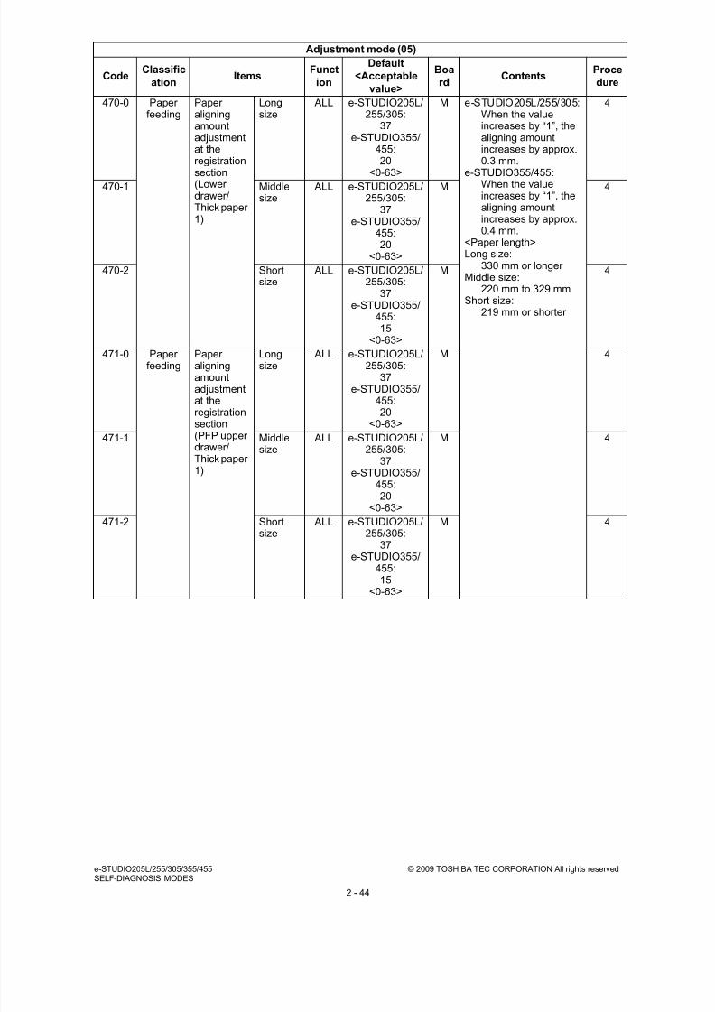
8/9/2019 Service manual E-studio 455
http://slidepdf.com/reader/full/service-manual-e-studio-455 72/670
e-STUDIO205L/255/305/355/455 © 2009 TOSHIBA TEC CORPORATION All rights reservedSELF-DIAGNOSIS MODES
2 - 44
470-0 Paperfeeding
Paperaligningamountadjustmentat theregistration
section(Lowerdrawer/Thick paper1)
Longsize
ALL e-STUDIO205L/255/305:
37e-STUDIO355/
455:20
<0-63>
M e-STUDIO205L/255/305:When the valueincreases by “1”, thealigning amountincreases by approx.0.3 mm.
e-STUDIO355/455:When the valueincreases by “1”, thealigning amountincreases by approx.0.4 mm.
<Paper length>Long size:
330 mm or longer Middle size:
220 mm to 329 mmShort size:
219 mm or shorter
4
470-1 Middlesize
ALL e-STUDIO205L/255/305:
37e-STUDIO355/
455:20
<0-63>
M 4
470-2 Shortsize
ALL e-STUDIO205L/255/305:
37e-STUDIO355/
455:15
<0-63>
M 4
471-0 Paperfeeding
Paperaligningamountadjustmentat theregistrationsection(PFP upperdrawer/Thick paper1)
Longsize
ALL e-STUDIO205L/255/305:
37e-STUDIO355/
455:20
<0-63>
M 4
471-1 Middlesize
ALL e-STUDIO205L/255/305:
37e-STUDIO355/
455:20
<0-63>
M 4
471-2 Shortsize
ALL e-STUDIO205L/255/305:
37e-STUDIO355/
455:15
<0-63>
M 4
Adjustment mode (05)
CodeClassific
ationItems
Funct
ion
Default
<Acceptable
value>
Boa
rdContents
Proce
dure

8/9/2019 Service manual E-studio 455
http://slidepdf.com/reader/full/service-manual-e-studio-455 73/670
© 2009 TOSHIBA TEC CORPORATION All rights reserved e-STUDIO205L/255/305/355/455SELF-DIAGNOSIS MODES
2 - 45
472-0 Paperfeeding
Paperaligningamountadjustmentat theregistration
section(PFP lowerdrawer/Thick paper1)
Longsize
ALL e-STUDIO205L/255/305:
37e-STUDIO355/
455:20
<0-63>
M e-STUDIO205L/255/305:When the valueincreases by “1”, thealigning amountincreases by approx.0.3 mm.
e-STUDIO355/455:When the valueincreases by “1”, thealigning amountincreases by approx.0.4 mm.
<Paper length>Long size:
330 mm or longer Middle size:
220 mm to 329 mmShort size:
219 mm or shorter
4
472-1 Middlesize
ALL e-STUDIO205L/255/305:
37e-STUDIO355/
455:20
<0-63>
M 4
472-2 Shortsize
ALL e-STUDIO205L/255/305:
37e-STUDIO355/
455:15
<0-63>
M 4
473 Paperfeeding
Paper aligning amountadjustment at theregistration section(LCF/Thick paper 1)
ALL e-STUDIO205L/255/305:
37e-STUDIO355/
455:15
<0-63>
M 1
474-0 Paperfeeding
Paperaligningamountadjustmentat theregistrationsection
(Duplexfeeding/Thick paper1)
Longsize
ALL 12<0-63>
M 4
474-1 Middlesize
ALL 12<0-63>
M 4
474-2 Shortsize
ALL 12<0-63>
M 4
497-0 Laser Adjustmentof drawersidewaysdeviation
Upperdrawer
ALL 128<0-255>
M When the valueincreases by “1”, theimage shifts toward thefront side by 0.0423 mm.
4
497-1 Lowerdrawer
ALL 128<0-255>
M 4
497-2 PFPupperdrawer
ALL 128<0-255>
M 4
497-3 PFPlowerdrawer
ALL 128<0-255>
M 4
497-4 LCF ALL 128<0-255>
M 4
497-5 Bypassfeeding
ALL 128<0-255>
M 4
498-0 Laser Adjustmentof primaryscanninglaserwriting startposition atduplexfeeding
Longsize
ALL 148<0-255>
M When the valueincreases by “1”, theimage shifts toward thefront side by 0.0423 mm.
4
498-1 Shortsize (A4/LT orsmaller)
ALL 148<0-255>
M 4
Adjustment mode (05)
CodeClassific
ationItems
Funct
ion
Default
<Acceptable
value>
Boa
rdContents
Proce
dure

8/9/2019 Service manual E-studio 455
http://slidepdf.com/reader/full/service-manual-e-studio-455 74/670
e-STUDIO205L/255/305/355/455 © 2009 TOSHIBA TEC CORPORATION All rights reservedSELF-DIAGNOSIS MODES
2 - 46
501 Image DensityadjustmentFineadjustmentof “manualdensity”/
Centervalue
Photo PPC 128<0-255>
SYS When the valueincreases, the image atthe center step becomesdarker.
1
503 Text/Photo
PPC 128<0-255>
SYS 1
504 Text PPC 128<0-255>
SYS 1
505 Image DensityadjustmentFineadjustmentof “manualdensity”/Light stepvalue
Text/Photo
PPC 20<0-255>
SYS When the valueincreases, the image ofthe “light” steps becomeslighter.
1
506 Photo PPC 20<0-255>
SYS 1
507 Text PPC 20<0-255>
SYS 1
508 Image DensityadjustmentFineadjustment
of “manualdensity”/Dark stepvalue
Text/Photo
PPC 20<0-255>
SYS When the valueincreases, the image ofthe “dark” steps becomesdarker.
1
509 Photo PPC 20<0-255>
SYS 1
510 Text PPC 20<0-255>
SYS 1
512 Image DensityadjustmentFineadjustmentof“automaticdensity”
Photo PPC 128<0-255>
SYS When the valueincreases, the imagebecomes darker.
1
514 Text/Photo
PPC 128<0-255>
SYS 1
515 Text PPC 128<0-255>
SYS 1
580 Image Automaticgammaadjustment
Allmediatypes
PPC - - • When color deviationis found in gradationreproduction, thegradation
reproduction of colorK can be correctedwith the automaticgamma adjustment.
• The result of thecorrection above willbe applied to allmedia types.
7
590-0 Image Gammabalanceadjustment(Text/Photo)
Lowdensity
PPC 128<0-255>
SYS The larger the value is,the darker the image ofthe area surrounding thetarget area becomes.
4
590-1 Mediumdensity
PPC 128<0-255>
SYS 4
590-2 Highdensity
PPC 128<0-255>
SYS 4
591-0 Image Gammabalanceadjustment(Text)
Lowdensity
PPC 128<0-255>
SYS 4
591-1 Mediumdensity
PPC 128<0-255>
SYS 4
591-2 Highdensity
PPC 128<0-255>
SYS 4
592-0 Image Gammabalanceadjustment(Photo)
Lowdensity
PPC 128<0-255>
SYS 4
592-1 Mediumdensity
PPC 128<0-255>
SYS 4
592-2 Highdensity
PPC 128<0-255>
SYS 4
Adjustment mode (05)
CodeClassific
ationItems
Funct
ion
Default
<Acceptable
value>
Boa
rdContents
Proce
dure

8/9/2019 Service manual E-studio 455
http://slidepdf.com/reader/full/service-manual-e-studio-455 75/670
© 2009 TOSHIBA TEC CORPORATION All rights reserved e-STUDIO205L/255/305/355/455SELF-DIAGNOSIS MODES
2 - 47
604 Image Sharpnessadjustment(Black)
Text/Photo
PPC 128<0-255>
SYS The larger the value is,the sharper the imagebecomes.The smaller the value is,the softer the imagebecomes and the less
moire appears.
1
605 Text PPC 128<0-255>
SYS 1
606 Photo PPC 128<0-255>
SYS 1
648 Image Smudged/faint textadjustment
Text/Photo
PPC 2<0-4>
SYS 0: Faint text issuppressed most.
4: Smudged text issuppressed most.
1
649 Text PPC 2<0-4>
SYS 1
654 Image Adjustmentofsmudged/faint text
PS PRT 5<0-9>
M Adjustment of thesmudged/faint text.With decreasing thevalue, the faint text issuppressed, and withincreasing it, thesmudged text issuppressed.
1
655 PCL PRT 5<0-9>
M 1
656 XPS PRT 5<0-9>
M 1
667-0 Image Setting
beam levelconversion
Beam
level 0/4
PPC 0
<0-10>
M The smaller the value is,
the narrower the beamwidth becomes and thesmaller the dots arereproduced.
4
667-1 Beamlevel 1/4
PPC 4<0-10>
M 4
667-2 Beamlevel 2/4
PPC 5<0-10>
M 4
667-3 Beamlevel 3/4
PPC 6<0-10>
M 4
667-4 Beamlevel 4/4
PPC 9<0-10>
M 4
672-0 Image Settingbeam levelconversion
Beamlevel 0/4
PRT 0<0-10>
M The smaller the value is,the narrower the beamwidth becomes and thesmaller the dots arereproduced.
4
672-1 Beamlevel 1/4
PRT 4<0-10>
M 4
672-2 Beamlevel 2/4
PRT 5<0-10>
M 4
672-3 Beamlevel 3/4
PRT 6<0-10>
M 4
672-4 Beamlevel 4/4
PRT 9<0-10>
M 4
678-0 Image Settingbeam levelconversion(FAX)
Beamlevel 0/4
FAX 0<0-10>
M The smaller the value is,the narrower the beamwidth becomes and thesmaller the dots arereproduced.
4
678-1 Beamlevel 1/4
FAX 4<0-10>
M 4
678-2 Beamlevel 2/4
FAX 5<0-10>
M 4
678-3 Beamlevel 3/4
FAX 6<0-10>
M 4
678-4 Beamlevel 4/4
FAX 10<0-10>
M 4
700 Image Adjustmentof binarizedthreshold(Text)
Centervalue
FAX 128<0-255>
SYS When the valueincreases, the image atthe center step becomesdarker.
1
710 Image DensityadjustmentFineadjustmentof “manualdensity”/Centervalue
Photo FAX 128<0-255>
SYS When the valueincreases, the image atthe center step becomesdarker.
1
714 Text/Photo
FAX 128<0-255>
SYS 1
Adjustment mode (05)
CodeClassific
ationItems
Funct
ion
Default
<Acceptable
value>
Boa
rdContents
Proce
dure

8/9/2019 Service manual E-studio 455
http://slidepdf.com/reader/full/service-manual-e-studio-455 76/670
e-STUDIO205L/255/305/355/455 © 2009 TOSHIBA TEC CORPORATION All rights reservedSELF-DIAGNOSIS MODES
2 - 48
725 Image DensityadjustmentFineadjustmentof“automatic
density”
Photo FAX 128<0-255>
SYS When the valueincreases, the imagebecomes darker.
1
729 Text/Photo
FAX 128<0-255>
SYS 1
840 Image Sharpnessadjustment
Text/Photo
NWSCN
(black)
128<0-255>
SYS The larger the value is,the sharper the imagebecomes. The smallerthe value is, the softerthe image becomes andthe less moire appears.
1
841 Text NWSCN
(black)
128<0-255>
SYS 1
842 Photo NWSCN
(black)
128<0-255>
SYS 1
843 Image
smoothing
NW
SCN(black
)
128
<0-255>
SYS 1
845 Image Densityadjustment(Manualadjustment/ Centervalue)
Text/Photo
NWSCN
(black)
128<0-255>
SYS The larger the value is,the darker the image ofthe center valuebecomes.
1
846 Text NWSCN
(black)
128<0-255>
SYS 1
847 Photo NWSCN
(black
)
128<0-255>
SYS 1
848 Imagesmoothi
ng
NWSCN
(black)
128<0-255>
SYS 1
860 Image DensityadjustmentFineadjustmentof“automaticdensity”
Text/Photo
NWSCN
(black)
128<0-255>
SYS When the valueincreases, the imagebecomes darker.
1
861 Text NWSCN
(black)
128<0-255>
SYS 1
862 Photo NW
SCN(black)
128
<0-255>
SYS 1
863 Imagesmoothing
NWSCN
(black)
128<0-255>
SYS 1
Adjustment mode (05)
CodeClassific
ationItems
Funct
ion
Default
<Acceptable
value>
Boa
rdContents
Proce
dure

8/9/2019 Service manual E-studio 455
http://slidepdf.com/reader/full/service-manual-e-studio-455 77/670
© 2009 TOSHIBA TEC CORPORATION All rights reserved e-STUDIO205L/255/305/355/455SELF-DIAGNOSIS MODES
2 - 49
880-0 Image Gammabalanceadjustment(Text/Photo)
Lowdensity
NWSCN
(black)
128<0-255>
SYS The larger the value is,the darker the image ofthe area surrounding thetarget area becomes.
4
880-1 Mediumdensity
NWSCN
(black)
128<0-255>
SYS 4
880-2 Highdensity
NWSCN
(black)
128<0-255>
SYS 4
881-0 Image Gammabalanceadjustment(Text)
Lowdensity
NWSCN
(black)
128<0-255>
SYS 4
881-1 Mediumdensity
NWSCN
(black)
128<0-255>
SYS 4
881-2 Highdensity
NWSCN
(black)
128<0-255>
SYS 4
882-0 Image Gammabalanceadjustment(Photo)
Lowdensity
NWSCN
(black)
128<0-255>
SYS 4
882-1 Mediumdensity
NWSCN
(black)
128<0-255>
SYS 4
882-2 Highdensity
NWSCN
(black)
128<0-255>
SYS 4
883-0 Image Gammabalanceadjustment(Imagesmoothing)
Lowdensity
NWSCN
(black)
128<0-255>
SYS The larger the value is,the darker the image ofthe area surrounding thetarget area becomes.
4
883-1 Mediumdensity
NWSCN
(black)
128<0-255>
SYS 4
883-2 Highdensity
NWSCN
(black)
128<0-255>
SYS 4
922 Image Sharpnessadjustment
User custom
PPC 128<0-255>
SYS The larger the value is,the sharper the imagebecomes. The smallerthe value is, the softerthe image becomes andthe less moire appears.
1
925 Image Smudged/faint textadjustment
User custom
PPC 2<0-4>
SYS 0: Faint text issuppressed most.
4: Smudged text issuppressed most.
1
Adjustment mode (05)
CodeClassific
ationItems
Funct
ion
Default
<Acceptable
value>
Boa
rdContents
Proce
dure

8/9/2019 Service manual E-studio 455
http://slidepdf.com/reader/full/service-manual-e-studio-455 78/670
e-STUDIO205L/255/305/355/455 © 2009 TOSHIBA TEC CORPORATION All rights reservedSELF-DIAGNOSIS MODES
2 - 50
931 Image DensityadjustmentFineadjustmentof “manualdensity”/
Centervalue
CustomMode 1
PPC 128<0-255>
SYS When the valueincreases, the image ofthe center step becomesdarker.
1
934 Image DensityadjustmentFineadjustmentof “manualdensity”/Light stepvalue
CustomMode 1
PPC 20<0-255>
SYS When the valueincreases, the image ofthe “light” step densitybecomes lighter.
1
937 Image DensityadjustmentFineadjustment
of “manualdensity”/Dark stepvalue
CustomMode 1
PPC 20<0-255>
SYS When the valueincreases, the image ofthe “dark” step densitybecomes darker.
1
940 Image DensityadjustmentFineadjustmentof“automaticdensity”
CustomMode 1
PPC 128<0-255>
SYS When the valueincreases, the imagebecomes darker.
1
949-0 Image Gammabalanceadjustment(User
custom)
Lowdensity
PPC 128<0-255>
SYS The larger the value is,the darker the image ofthe target area becomes.
4
949-1 Mediumdensity
PPC 128<0-255>
SYS 4
949-2 Highdensity
PPC 128<0-255>
SYS 4
976 Maintenance
Equipment number(serial number) entry
ALL - SYS When this adjustment isperformed with this code,the setting code (08-995)is also performedautomatically (10 digits).
1
1070 Image Backgroundadjustment
Text SCN(color
)
50<0-50>
SYS The smaller the value is,the lighter thebackground becomes.
1
1071 Printedimage
SCN(color
)
50<0-50>
SYS 1
1072 Photo SCN(color
)
50<0-50>
SYS 1
1075 Image Fineadjustmentof blackdensity
Text SCN(color
)
0<0-4>
SYS The larger the value is,the darker the black sideof the image becomes.
1
1076 Printedimage
SCN(color
)
0<0-4>
SYS 1
1077 Photo SCN(color
)
0<0-4>
SYS 1
Adjustment mode (05)
CodeClassific
ationItems
Funct
ion
Default
<Acceptable
value>
Boa
rdContents
Proce
dure

8/9/2019 Service manual E-studio 455
http://slidepdf.com/reader/full/service-manual-e-studio-455 79/670
© 2009 TOSHIBA TEC CORPORATION All rights reserved e-STUDIO205L/255/305/355/455SELF-DIAGNOSIS MODES
2 - 51
1080 Image RGBconversionmethodselection
Text SCN(color
)
0<0-3>
SYS Sets the color spaceformat of the outputimage.0: sRGB1: AppleRGB2: ROMMRGB
3: AdobeRGB
1
1081 Printedimage
SCN(color
)
0<0-3>
SYS 1
1082 Photo SCN(color
)
0<0-3>
SYS 1
1086 Image Sharpnessadjustment
Text SCN(color
)
128<0-255>
SYS The larger the value is,the sharper the imagebecomes. The smallerthe value is, the softerthe image becomes andthe less moire appears.
1
1087 Printedimage
SCN(color
)
128<0-255>
SYS 1
1088 Photo SCN(color
)
128<0-255>
SYS 1
1675 Image ACS judgmentthreshold
SCN 70<0-255>
SYS The larger the value is,the more an originaltends to be judged asblack even at the autocolor mode. The smallervalue is, the more it tendsto be judged as color.
1
2083 Imageprocessi
ng
Transfer cleaning biasadjustment (positive)
ALL e-STUDIO205L/255/305:
63e-STUDIO355/
455:96
<0-255>
M When the high-voltagetransformer is replaced,the transfer cleaning biasneeds to be adjusted withthis code.The larger the settingvalue is, the higher thevalue of the current(more positive) is. This
causes a reduction in thetoner adhering to thetransfer roller and animprovement in thecleaning performance.Perform this adjustmentafter the process units(cleaner and developerunit) have been removed.When the high-voltagetransformer is replaced,adjusting with thefollowing codes needs tobe performed in additionto this adjustment.
05-205, 05-210, 05-221,05-234
3
Adjustment mode (05)
CodeClassific
ationItems
Funct
ion
Default
<Acceptable
value>
Boa
rdContents
Proce
dure

8/9/2019 Service manual E-studio 455
http://slidepdf.com/reader/full/service-manual-e-studio-455 80/670
e-STUDIO205L/255/305/355/455 © 2009 TOSHIBA TEC CORPORATION All rights reservedSELF-DIAGNOSIS MODES
2 - 52
2084 Imageprocessi
ng
Transfer cleaning biasadjustment (negative)
ALL 41<0-255>
M When the high-voltagetransformer is replaced,the transfer cleaning biasneeds to be adjusted withthis code.The larger the setting
value is, the higher thevalue of the current(more negative) is. Thiscauses a reduction in thetoner adhering to thetransfer roller and animprovement in thecleaning performance.Perform this adjustmentafter the process units(cleaner and developerunit) have been removed.When the high-voltagetransformer is replaced,adjusting with the
following codes need tobe performed in additionto this adjustment.05-205, 05-210, 05-221,05-234
3
7025 Image Background offsetadjustment for RADF
PPC 128<0-255>
SYS The larger theadjustment value is, thelighter the backgroundbecomes. The smallerthe adjustment value is,the darker thebackground becomes.
1
7033 Image Background
adjustment(Automaticdensityadjustment)
Text/Photo
PPC 128<0-255>
SYS The larger the value is,the lighter the
background becomes.The larger the value is,the lighter thebackground becomes.
1
7034 Image Text PPC 128<0-255>
SYS 1
7041 Image Backgroundadjustment(Manualdensityadjustment)
Text/Photo
PPC 128<0-255>
SYS 1
7042 Image Text PPC 128<0-255>
SYS 1
7043 Image Backgroundadjustment(Automaticdensity
adjustment)
Photo PPC 128<0-255>
SYS 1
7048 Image Backgroundadjustment(Black /Manualdensityadjustment)
Photo PPC 128<0-255>
SYS 1
Adjustment mode (05)
CodeClassific
ationItems
Funct
ion
Default
<Acceptable
value>
Boa
rdContents
Proce
dure

8/9/2019 Service manual E-studio 455
http://slidepdf.com/reader/full/service-manual-e-studio-455 81/670
© 2009 TOSHIBA TEC CORPORATION All rights reserved e-STUDIO205L/255/305/355/455SELF-DIAGNOSIS MODES
2 - 53
7236 Image Rangecorrectionadjustment(Automaticdensityadjustment)
User custom
PPC 1<0-1>
SYS 0: Background peak -Fixed
1: Background peak -Varied
1
7237 Image Rangecorrectionadjustment(Manualdensityadjustment)
User custom
PPC 1<0-1>
SYS 1
7279 Image Backgroundadjustment(Automaticdensityadjustment)
User custom
PPC 128<0-255>
SYS The larger the value is,the lighter thebackground becomes.
1
7280 Image Background
adjustment(Manualdensityadjustment)
User custom
PPC 128<0-255>
SYS 1
7283 Image Rangecorrectionadjustment(Automaticdensityadjustment)
Text/Photo
PPC 1<0-1>
SYS 0: Background peak -Fixed
1: Background peak -Varied
1
7284 Image Text PPC 1<0-1>
SYS 1
7285 Image Photo PPC 1<0-1>
SYS 1
7286 Image Rangecorrectionadjustment(Manual
densityadjustment)
Text/Photo
PPC 1<0-1>
SYS 0: Background peak -Fixed
1: Background peak -Varied
1
7287 Image Text PPC 1<0-1>
SYS 1
7288 Image Photo PPC 0<0-1>
SYS 1
7315-0 Image Gammabalanceadjustment(PS /Smooth /600dpi)
L PRT 128<0-255>
SYS When the valueincreases, the density inthe target area becomeshigher.L: Low density areaM: Medium density areaH: High density area
4
7315-1 M PRT 128<0-255>
SYS 4
7315-2 H PRT 128<0-255>
SYS 4
7316-0 Image Gammabalanceadjustment(PS / Detail/ 600dpi)
L PRT 128<0-255>
SYS When the valueincreases, the density inthe target area becomeshigher.L: Low density area
M: Medium density areaH: High density area
4
7316-1 M PRT 128<0-255>
SYS 4
7316-2 H PRT 128
<0-255>
SYS 4
7317-0 Image Gammabalanceadjustment(PCL /Smooth /600dpi)
L PRT 128<0-255>
SYS When the valueincreases, the density inthe target area becomeshigher.L: Low density areaM: Medium density areaH: High density area
4
7317-1 M PRT 128<0-255>
SYS 4
7317-2 H PRT 128<0-255>
SYS 4
Adjustment mode (05)
CodeClassific
ationItems
Funct
ion
Default
<Acceptable
value>
Boa
rdContents
Proce
dure

8/9/2019 Service manual E-studio 455
http://slidepdf.com/reader/full/service-manual-e-studio-455 82/670
e-STUDIO205L/255/305/355/455 © 2009 TOSHIBA TEC CORPORATION All rights reservedSELF-DIAGNOSIS MODES
2 - 54
7318-0 Image Gammabalanceadjustment(PCL /Detail /600dpi)
L PRT 128<0-255>
SYS When the valueincreases, the density inthe target area becomeshigher.L: Low density areaM: Medium density area
H: High density area
4
7318-1 M PRT 128<0-255>
SYS 4
7318-2 H PRT 128<0-255>
SYS 4
7319-0 Image Gammabalanceadjustment(XPS /Smooth /600dpi)
L PRT 128<0-255>
SYS When the valueincreases, the density inthe target area becomeshigher.L: Low density areaM: Medium density areaH: High density area
4
7319-1 M PRT 128<0-255>
SYS 4
7319-2 H PRT 128<0-255>
SYS 4
7320-0 Image Gammabalanceadjustment(XPS /Detail /600dpi)
L PRT 128<0-255>
SYS When the valueincreases, the density inthe target area becomeshigher.L: Low density areaM: Medium density area
H: High density area
4
7320-1 M PRT 128<0-255>
SYS 4
7320-2 H PRT 128<0-255>
SYS 4
7351-0 Image Settingbeam levelconversion(PRTHardcopysecurityprinting)
Beamlevel 0/4
PRT 0<0-10>
M The smaller the value is,the narrower the beamwidth becomes and thesmaller the dots arereproduced.
4
7351-1 Beamlevel 1/4
PRT 4<0-10>
M 4
7351-2 Beamlevel 2/4
PRT 5<0-10>
M 4
7351-3 Beamlevel 3/4
PRT 6<0-10>
M 4
7351-4 Beamlevel 4/4
PRT 9<0-10>
M 4
7352-0 Image Settingbeam levelconversion
(PRT Tonersaving)
Beamlevel 0/4
PRT 0<0-10>
M The smaller the value is,the narrower the beamwidth becomes and the
smaller the dots arereproduced.
4
7352-1 Beam
level 1/4
PRT 2
<0-10>
M 4
7352-2 Beamlevel 2/4
PRT 3<0-10>
M 4
7352-3 Beamlevel 3/4
PRT 4<0-10>
M 4
7352-4 Beamlevel 4/4
PRT 6<0-10>
M 4
7416 Image Rangecorrectionadjustment(Black /
Automaticdensityadjustment)
Text/Photo
SCN(black
)
1<0-1>
SYS 0: Background peak -Fixed
1: Background peak -Varied
1
7417 Text SCN(black
)
1<0-1>
SYS 1
7418 Photo SCN(black
)
1<0-1>
SYS 1
7419 Imagesmoothing
SCN(black
)
1<0-1>
SYS 1
Adjustment mode (05)
CodeClassific
ationItems
Funct
ion
Default
<Acceptable
value>
Boa
rdContents
Proce
dure

8/9/2019 Service manual E-studio 455
http://slidepdf.com/reader/full/service-manual-e-studio-455 83/670
© 2009 TOSHIBA TEC CORPORATION All rights reserved e-STUDIO205L/255/305/355/455SELF-DIAGNOSIS MODES
2 - 55
7421 Image Rangecorrectionadjustment(Black /Manualdensity
adjustment)
Text/Photo
SCN(black
)
0<0-1>
SYS 0: Background peak -Fixed
1: Background peak -Varied
1
7422 Text SCN(black
)
0<0-1>
SYS 1
7423 Photo SCN(black
)
0<0-1>
SYS 1
7424 Imagesmoothing
SCN(black
)
0<0-1>
SYS 1
7425 Image Rangecorrectionadjustment(Black /
Automaticdensityadjustment)
User custom
SCN(black
)
1<0-1>
SYS 0: Background peak -Fixed
1: Background peak -Varied
1
7426 Image Range
correctionadjustment(Black /Manualdensityadjustment)
User
custom
SCN
(black)
0
<0-1>
SYS 1
7468 Image Background offsetadjustment for RADF
SCN(black
)
128<0-255>
SYS The larger the value is,the lighter thebackground becomes.
1
7470 Image Sharpnessadjustment(Black)
User custom
SCN(black
)
128<0-255>
SYS The larger the value is,the sharper the imagebecomes. The smallerthe value is, the softerthe image becomes and
the less moire appears.
1
7475 Image DensityadjustmentManualdensityadjustment/ Centervalue
User custom
SCN(black
)
128<0-255>
SYS The larger the value is,the darker the image atthe center valuebecomes.
1
7478 Image Densityadjustment
Automaticdensityadjustment
User custom
SCN(black
)
128<0-255>
SYS The larger the value is,the larger thesurrounding marginbecomes.
1
7480-0 Image Gammabalanceadjustment(Usercustom)
L SCN(black
)
128<0-255>
SYS The larger the value is,the darker the image ofthe area surrounding thetarget area becomes.L: Low density areaM: Medium density areaH: High density area
4
7480-1 M SCN(black
)
128<0-255>
SYS 4
7480-2 H SCN(black
)
128<0-255>
SYS 4
7489 Image Amount of surroundingvoid (networkscanning)
SCN 0<0-255>
SYS The larger the value is,the darker the imagebecomes.
1
Adjustment mode (05)
CodeClassific
ationItems
Funct
ion
Default
<Acceptable
value>
Boa
rdContents
Proce
dure

8/9/2019 Service manual E-studio 455
http://slidepdf.com/reader/full/service-manual-e-studio-455 84/670
e-STUDIO205L/255/305/355/455 © 2009 TOSHIBA TEC CORPORATION All rights reservedSELF-DIAGNOSIS MODES
2 - 56
7618 Image Blank page judgmentthreshold adjustment
PPC/SCN
128<0-255>
SYS The larger the value is,the more the originaltends to be judged as ablank page.
1
8325 Image Saturationadjustment
Text SCN(color
)
128<0-255>
SYS The larger the value is,the brighter the image
becomes. The smallerthe value is, the duller theimage becomes.
1
8326 Photo SCN(color
)
128<0-255>
SYS 1
8327 Printedimage
SCN(color
)
128<0-255>
SYS 1
8330 Image Rangecorrectionadjustment(Full color /
Automaticdensityadjustment)
Text SCN(color
)
1<0-1>
SYS 0: Background peak -Fixed
1: Background peak -Varied
1
8331 Printedimage
SCN(color
)
1<0-1>
SYS 1
8332 Photo SCN(color
)
1<0-1>
SYS 1
8334 User custom
SCN(color
)
1<0-1>
SYS 1
8340 Image DensityadjustmentManualadjustment/ Centervalue
Text SCN(color
)
128<0-255>
SYS The larger the value is,the darker the image atthe center valuebecomes.
1
8341 Printedimage
SCN(color
)
128<0-255>
SYS 1
8342 Photo SCN(color
)
128<0-255>
SYS 1
8344 Image DensityadjustmentManualadjustment/ Light stepvalue
Text SCN(color
)
20<0-255>
SYS Sets the changingamount per step of thedensity adjustmentbuttons on the controlpanel.The larger the value is,the lighter the image ofthe “light” step becomes.
1
8345 Printedimage
SCN(color
)
20<0-255>
SYS 1
8346 Photo SCN(color
)
20<0-255>
SYS 1
8348 Image Densityadjustment(Manualadjustment/ Dark step
value)
Text SCN(color
)
20<0-255>
SYS Sets the changingamount per step of thedensity adjustmentbuttons on the controlpanel.
The larger the value is,the darker the image ofthe “dark” step becomes.
1
8349 Printedimage
SCN(color
)
20<0-255>
SYS 1
8350 Photo SCN(color
)
20<0-255>
SYS 1
Adjustment mode (05)
CodeClassific
ationItems
Funct
ion
Default
<Acceptable
value>
Boa
rdContents
Proce
dure

8/9/2019 Service manual E-studio 455
http://slidepdf.com/reader/full/service-manual-e-studio-455 85/670
© 2009 TOSHIBA TEC CORPORATION All rights reserved e-STUDIO205L/255/305/355/455SELF-DIAGNOSIS MODES
2 - 57
8361 Image Rangecorrectionadjustment(Full color /Manualdensity
adjustment)
Text SCN(color
)
0<0-1>
SYS 0: Background peak -Fixed
1: Background peak -Varied
1
8362 Printedimage
SCN(color
)
0<0-1>
SYS 1
8363 Photo SCN(color
)
0<0-1>
SYS 1
8365 User custom
SCN(color
)
0<0-1>
SYS 1
8370 Image Background fineadjustment
Usercustommode
SCN(color
)
50<0-50>
SYS When the valueincreases, thebackground becomesdarker.
1
8371 Image Adjustmentof blackdensity
Usercustommode
SCN(color
)
0<0-4>
SYS Adjusts the black densityof the scanned image.When the valueincreases, the black
density becomes darker.
1
8372 Image RGBconversionmethodselection
Usercustommode
SCN(color
)
0<0-3>
SYS Sets the color spaceformat of the outputimage.0: sRGB1: AppleRGB2: ROMMRGB3: AdobeRGB
1
8373 Image Saturationadjustment
Usercustommode
SCN(color
)
128<0-255>
SYS The larger the value is,the brighter the imagebecomes. The smallerthe value is, the duller theimage becomes.
1
8375 Image Sharpness
adjustment
User
custommode
SCN
(color )
128
<0-255>
SYS When the value
increases, the imagebecomes sharper. Whenthe value decreases, theimage becomes softer.The smaller the value is,the less the moirebecomes.
1
8380 Image Densityadjustment(Manualadjustment/Centervalue)
Usercustommode
SCN(color
)
128<0-255>
SYS The larger the value is,the darker the image ofthe center step densitybecomes.
1
8381 Image Densityadjustment(Manualadjustment/Light stepvalue)
Usercustommode
SCN(color
)
20<0-255>
SYS Sets the changingamount by 1 step atdensity adjustment onthe control panelThe larger the value is,the lighter the image ofthe light steps becomes.
1
8382 Image Densityadjustment(Manualadjustment/Dark stepvalue)
Usercustommode
SCN(color
)
20<0-255>
SYS Sets the changingamount by 1 step atdensity adjustment onthe control panelThe larger the value is,the darker the image ofthe dark steps becomes.
1
Adjustment mode (05)
CodeClassific
ationItems
Funct
ion
Default
<Acceptable
value>
Boa
rdContents
Proce
dure

8/9/2019 Service manual E-studio 455
http://slidepdf.com/reader/full/service-manual-e-studio-455 86/670
e-STUDIO205L/255/305/355/455 © 2009 TOSHIBA TEC CORPORATION All rights reservedSELF-DIAGNOSIS MODES
2 - 58
8385 Image Background offsetadjustment(Automaticdensityadjustment)
Text SCN(color
)
128<0-255>
SYS The larger the value is,the less easily thebackground (low densityarea) is printed. Thesmaller the value is, themore easily the
background (low densityarea) is printed.
1
8386 Printedimage
SCN(color
)
128<0-255>
SYS 1
8387 Photo SCN(color
)
128<0-255>
SYS 1
8389 Usercustommode
SCN(color
)
128<0-255>
SYS 1
8390 Image Background offsetadjustment(Manualdensityadjustment)
Text SCN(color
)
128<0-255>
SYS The larger the value is,the less easily thebackground (low densityarea) is printed. Thesmaller the value is, themore easily thebackground (low densityarea) is printed.
1
8391 Printedimage
SCN(color
)
128<0-255>
SYS 1
8392 Photo SCN(color
)
128<0-255>
SYS 1
8394 Usercustommode
SCN(color
)
128<0-255>
SYS 1
8395 Image Background offsetadjustment for RADF
SCN(color
)
128<0-255>
SYS The larger theadjustment value is, thelighter the backgroundbecomes.
1
8400 Image Background offsetadjustment(Automaticdensityadjustment)
Text/Photo
SCN(black
)
128<0-255>
SYS The larger the value is,the less easily thebackground (low densityarea) is printed. Thesmaller the value is, themore easily the
background (low densityarea) is printed.
1
8402 Photo SCN(black
)
128<0-255>
SYS 1
8403 Grayscale
SCN(black
)
128<0-255>
SYS 1
8404 Usercustommode
SCN(black
)
128<0-255>
SYS 1
8405 Image Background offsetadjustment(Manualdensityadjustment)
Text/Photo
SCN(black
)
128<0-255>
SYS The larger the value is,the less easily thebackground (low densityarea) is printed. Thesmaller the value is, themore easily thebackground (low densityarea) is printed.
1
8407 Photo SCN(black
)
128<0-255>
SYS 1
8408 Grayscale
SCN(black
)
128<0-255>
SYS 1
8409 Usercustommode
SCN(black
)
128<0-255>
SYS 1
9096 General Display of executionhistory in theproduction lineprocess
ALL - SYS Displays the executionhistory in the productionline process. The Formatis as follows:Number: OK/NG/-
2
Adjustment mode (05)
CodeClassific
ationItems
Funct
ion
Default
<Acceptable
value>
Boa
rdContents
Proce
dure

8/9/2019 Service manual E-studio 455
http://slidepdf.com/reader/full/service-manual-e-studio-455 87/670
© 2009 TOSHIBA TEC CORPORATION All rights reserved e-STUDIO205L/255/305/355/455SELF-DIAGNOSIS MODES
2 - 59
9104 Image Compression quality ofs SLIM PDFbackgroundprocessing
SCN(color
)
5<0-10>
SYS 0-100: High compression,
low image quality10: Low compression,
high image quality
1
9107 Image Resolution adjustment
of SLIM PDFbackgroundprocessing
SCN
(color )
1
<0-3>
SYS 0: 75dpi
1: 100dpi2: 150dpi3: 200dpi
1
Adjustment mode (05)
CodeClassific
ationItems
Funct
ion
Default
<Acceptable
value>
Boa
rdContents
Proce
dure

8/9/2019 Service manual E-studio 455
http://slidepdf.com/reader/full/service-manual-e-studio-455 88/670
e-STUDIO205L/255/305/355/455 © 2009 TOSHIBA TEC CORPORATION All rights reservedSELF-DIAGNOSIS MODES
2 - 60
2.7 Setting Mode (08)The items in the setting code list can be set or changed in this setting mode (08).
2.7.1 Operation procedure
Procedure 1
* Press [FUNCTION CLEAR] to enter minus (-).
Procedure 2
Procedure 3
Procedure 4
* Press [FUNCTION CLEAR] to enter minus (-).
Procedure 5
(Stores value in RAM)
[0][8]
[POWER]
[POWER] OFF/ON
(Exit)
[Digital key]
(Code) [START]
[Digital key]
*[FUNCTION CLEAR]
[ENTER]
or [INTERRUPT]Sets or
changes value
[CLEAR]
(Corrects value)
[CANCEL]
[0][8]
[POWER][POWER]OFF/ON
(Exit)
[Digital key]
(Code)[START]
[ENTER]
or
[INTERRUPT]
Adjustment value
cannot be changed
[0][8]
[POWER]
[POWER] OFF/ON
(Exit)[Digital key]
(Code)[START]
[CANCEL] or [CLEAR]
(Automatic setting)
[ENTER]
or
[INTERRUPT](Stores value in RAM)
[0][8][POWER]
[POWER]
OFF/ON(Exit)
[Digital key](Code)
[Digital key](Sub-code)
[Digital key]
* [FUNCTION CLEAR]Sets or
changes value
[START] [START]
[ENTER]
or [INTERRUPT](Stores value
in RAM)
[CLEAR]
(Corrects value)
[CLEAR]
(Corrects value)
[START]
[CANCEL]
[0][8]
[POWER]
[POWER] OFF/ON
(Exit)
[Digital key]
(Code)[Digital key][START]
[CANCEL][ENTER]
or
[INTERRUPT]
[CLEAR]
(Corrects value)
(Stores value in RAM)Sets or
changes value

8/9/2019 Service manual E-studio 455
http://slidepdf.com/reader/full/service-manual-e-studio-455 89/670
© 2009 TOSHIBA TEC CORPORATION All rights reserved e-STUDIO205L/255/305/355/455SELF-DIAGNOSIS MODES
2 - 61
Procedure 7
Procedure 9
Procedure 10
Procedure 11 and 12
*1. Press [PAUSE] to enter “-”, when entering telephone number.
*2. The data are stored in SYS-RAM in procedure 11 and stored in NIC-RAM in procedure 12.
Procedure 14
[0][8]
[POWER] [POWER] OFF/ON
(Exit)
[Digital key]
(Code)
[Digital key]
(Setting)
[CLEAR]
(Corrects value)
[START] (HDD formatting)
[CANCEL][ENTER]
or
[INTERRUPT]
(Stores value in RAM)
[0][8]
[POWER]
[POWER] OFF/ON
(Exit)
[Digital key]
(Code)[Select icon][START]
[CANCEL][ENTER]
or
[INTERRUPT]
[CLEAR](Corrects value)
(Stores value in RAM)
[0][8]
[POWER]
[POWER]
OFF/ON
(Exit)
[Digital key]
(Code)
[Digital key]
(1st setting)
[Digital key]
(2nd setting)[START] [START]
[CANCEL]
[ENTER]or
[INTERRUPT]
[CLEAR]
(Corrects value)
[CLEAR](Corrects value)
(Stores value in RAM)
[0][8]
[POWER]
[POWER] OFF/ON
(Exit)
[Digital key]
(Code)
[Digital key]
or
[Software keyboard][START]
[CANCEL]
[CLEAR](Corrects value)
*2(Stores value in RAM)*1 [PAUSE]
Sets or
changes value
[ENTER]
[0][8]
[POWER][POWER]
OFF/ON
(Exit)
[Digital key]
(Code)
[Digital key]
(Sub-code)
[CLEAR]
(Corrects value)
[START] [START]
[CANCEL][ENTER]
or
[INTERRUPT]
Adjustment value
cannot be changed

8/9/2019 Service manual E-studio 455
http://slidepdf.com/reader/full/service-manual-e-studio-455 90/670
e-STUDIO205L/255/305/355/455 © 2009 TOSHIBA TEC CORPORATION All rights reservedSELF-DIAGNOSIS MODES
2 - 62
2.7.2 Setting codes
Notes:
• The digit after the hyphen in “Code” of the following table is a sub code.
• In "Board", the SRAM of the board in which the data of each code is stored is indicated. "M"
stands for the LGC board, "SYS", "NIC" and "UTY" stands for the SYS board.
Setting mode (08)
Code Classification Items Function
Default
<Acceptablevalue>
Board Contents Procedure
200 General Date and time setting ALL -<13 digits>
- Year/month/date/day/hour/minute/secondExample:
03 07 0 13 13 27 48“Day” - “0” is for“Sunday”. ProceedsMonday throughSaturday from “1” to“6”.
5
201 General Destination selection ALL EUR: 0UC: 1JPN: 2
<0-2>
M 0: EUR1: UC2: JPN
1
202 Userinterface
Counter installedexternally
ALL 0<0-4>
M 0: No external counter 1: Coin controller 2: Copy key card
(This value is validonly when “2” is setto 08-201.)
3: Key copy counter 4: Key card for OEM1
1
203 General Line adjustment mode ALL 0<0-1>
M 0: For factoryshipment
1: For line* Field: “0” must be
selected
1
204 Userinterface
Auto-clear timer setting ALL 3<0-10>
SYS Timer to return theequipment to thedefault settings whenthe [START] button isnot pressed after thefunction and the modeare set0: Not cleared1 to 10:Set number x 15
sec.
1
205 Userinterface
Auto power save modetimer setting
ALL 4<0-15>
SYS Timer to automaticallyswitch to the Autopower save mode whenthe equipment has notbeen used
0: Invalid4: 1min.5: 2min.7: 4min.8: 5min.9: 7min.10:10min.11: 15min.12:20min.13:30min.14:45min.15:60min.
1

8/9/2019 Service manual E-studio 455
http://slidepdf.com/reader/full/service-manual-e-studio-455 91/670
© 2009 TOSHIBA TEC CORPORATION All rights reserved e-STUDIO205L/255/305/355/455SELF-DIAGNOSIS MODES
2 - 63
206 Userinterface
Auto Shut Off Modetimer setting (Auto ShutOff Mode/Sleep Mode)
ALL 21<0-21>
SYS Timer to turn OFF thepower or to enter theSleep Modeautomatically when theequipment has notbeen used
0: 3min. 1: 5min.2: 10min. 3: 15min.4: 20min. 5: 25min.6: 30min. 7: 40min.8: 50min. 9: 60min.10: 70min.11: 80min.12: 90min.13: 100min.14: 110min.15: 120min.16: 150min.17: 180min.18: 210min.19: 240min.
20: Disabled21: 1min.
1
207 Userinterface
Highlighting display onLCD
ALL 0<0-1>
SYS 0: Black letter on whitebackground
1: White letter on blackbackground
1
209 Userinterface
Default setting of filingformat when E-mailing
ALL 1<0-6>
SYS 0: TIFF (Multi)1: PDF (Multi)3: TIFF (Single)4: PDF (Single)5: XPS (Multi)6: XPS (Single)
1
210 Paperfeeding
Paper size (A6-R)feeding/widthwise
direction
PRT 148/105<148-432/
105-297>
M 10
218 Userinterface
Default setting of filingformat when storing files(at color/ACS modes)
SCN(color)
1<0-8>
SYS 0: TIFF (Multi)1: PDF (Multi)2: JPG3: TIFF (Single)4: PDF (Single)5: SLIM PDF (Multi)6: SLIM PDF (Single)7: XPS (Multi)8: XPS (Single)
1
219 Userinterface
Default setting of filingformat when storing files
SCN 0<0-6>
SYS 0: TIFF (Multi)1: PDF (Multi)3: TIFF (Single)4: PDF (Single)5: XPS (Multi)6: XPS (Single)
1
Setting mode (08)
CodeClassific
ationItems
Functi
on
Default
<Acceptable
value>
Boa
rdContents
Proce
dure

8/9/2019 Service manual E-studio 455
http://slidepdf.com/reader/full/service-manual-e-studio-455 92/670
e-STUDIO205L/255/305/355/455 © 2009 TOSHIBA TEC CORPORATION All rights reservedSELF-DIAGNOSIS MODES
2 - 64
220 Userinterface
Language displayed atpower-ON
ALL JPN: 5NAD/MJD/SAD/ASU/
ASD/AUD/ ARD: 0
TWD/CND/
KRD: 5<0-13>
SYS 0: Language 1 (English)1: Language 2(German)2: Language 3 (French)3: Language 4(Spanish)
4: Language 5 (Italian)5: Language 6(Japanese/Chinese/Taiwanese/Korean)6: Language 7 (BritishEnglish)7: Language 8 (Danish)8: Language 9 (Finnish)9: Language 10(Norwegian)10: Language 11(Swedish)11: Language 12(Dutch)12: Language 13
(Polish)13: Language 14(Russian)
1
221 Userinterface
Language selection in UIdata at Web power ON
ALL JPN: 5NAD/MJD/SAD/ASU/
ASD/AUD/ ARD: 0
TWD/CND/KRD: 5<0-13>
SYS 0: Language 1 (English)1: Language 2(German)2: Language 3 (French)3: Language 4(Spanish)4: Language 5 (Italian)5: Language 6(Japanese/Chinese/Taiwanese/Korean)6: Not used(nonenterable)7: Language 8 (Danish)8: Language 9 (Finnish)9: Language 10(Norwegian)10: Language 11(Swedish)11: Not used(nonenterable)12: Language 13(Polish)13: Language 14(Russian)
1
223 Maintenance
Switching of outputpages/ driving counts at
K-PM
ALL 0<0-2>
M Selects the reference tonotify the PM timing.
(The message isdisplayed on the LCDscreen.)0: PM counter (The
number of outputpages is set at 08-251.)
1: PM time counter(The timing is set at08-375.)
2: Whichever comesfaster
1
224 Paperfeeding
Paper size for bypassfeed
PPC - SYS Press the button on theLCD to select the size.
9
Setting mode (08)
CodeClassific
ationItems
Functi
on
Default
<Acceptable
value>
Boa
rdContents
Proce
dure

8/9/2019 Service manual E-studio 455
http://slidepdf.com/reader/full/service-manual-e-studio-455 93/670
© 2009 TOSHIBA TEC CORPORATION All rights reserved e-STUDIO205L/255/305/355/455SELF-DIAGNOSIS MODES
2 - 65
225 Paperfeeding
Paper size for upperdrawer
ALL EUR: A4UC: LT
JPN: A4
M Press the button on theLCD to select the size.
9
226 Paperfeeding
Paper size for lowerdrawer
ALL EUR: A3UC: LDJPN: A3
M Press the button on theLCD to select the size.
9
227 Paperfeeding
Paper size for PFPupper drawer
ALL EUR: A4-RUC: LT-R
JPN: A4-R
M Press the button on theLCD to select the size.
9
228 Paperfeeding
Paper size for PFP lowerdrawer
ALL EUR: A4UC: LGJPN: B4
M Press the button on theLCD to select the size.
9
229 Paperfeeding
Paper size (A3) feeding/widthwise direction
ALL 420/297<182-432/140-297>
M 10
230 Paperfeeding
Paper size (A4-R)feeding/widthwisedirection
ALL 297/210<182-432/140-297>
M 10
231 Paperfeeding
Paper size (A5-R)feeding/widthwisedirection
ALL 210/148<182-432/140-297>
M 10
232 Paperfeeding
Paper size (B4-R)feeding/widthwisedirection
ALL 364/257<182-432/140-297>
M 10
233 Paperfeeding
Paper size (B5-R)feeding/widthwisedirection
ALL 257/182<182-432/140-297>
M 10
234 Paperfeeding
Paper size (LT-R)feeding/widthwisedirection
ALL 279/216<182-432/140-297>
M 10
235 Paperfeeding
Paper size (LD-R)feeding/widthwisedirection
ALL 432/279<182-432/140-297>
M 10
236 Paperfeeding
Paper size (LG-R)feeding/widthwisedirection
ALL 356/216<182-432/140-297>
M 10
237 Paperfeeding
Paper size (ST-R)feeding/widthwisedirection
ALL 216/140<182-432/140-297>
M 10
238 Paperfeeding
Paper size(COMPUTER-R)feeding/widthwisedirection
ALL 356/257<182-432/140-297>
M 10
239 Paperfeeding
Paper size (FOLIO)feeding/widthwisedirection
ALL 330/210<182-432/140-297>
M 10
240 Paperfeeding
Paper size (13” LG-R)feeding/widthwisedirection
ALL 330/216<182-432/140-297>
M 10
241 Paperfeeding
Paper size (8.5”X8.5”-R)feeding/widthwisedirection
ALL 216/216<182-432/140-297>
M 10
242 Paperfeeding
Paper size (Non-standard) feeding/widthwise direction
ALL 432/279<148-432/105-297>
SYS 10
243 Paperfeeding
Memory 1Paper size (bypassfeeding/non-standardtype) feeding/widthwisedirection
ALL 148/100<148-432/100-297>
SYS Registers the papersize of bypass feed(non-standard type) into[MEMORY 1].
10
Setting mode (08)
CodeClassific
ationItems
Functi
on
Default
<Acceptable
value>
Boa
rdContents
Proce
dure

8/9/2019 Service manual E-studio 455
http://slidepdf.com/reader/full/service-manual-e-studio-455 94/670
e-STUDIO205L/255/305/355/455 © 2009 TOSHIBA TEC CORPORATION All rights reservedSELF-DIAGNOSIS MODES
2 - 66
244 Paperfeeding
Paper size (8K-R)feeding/widthwisedirection
ALL 390/270<182-432/140-297>
M 10
245 Paperfeeding
Paper size (16K-R)feeding/widthwisedirection
ALL 270/195<182-432/140-297>
M 10
247 Paperfeeding
Memory 2Paper size (bypassfeeding/non-standardtype) feeding/widthwisedirection
ALL 148/100<148-432/100-297>
SYS Registers the papersize of bypass feed(non-standard type) into[MEMORY 2].
10
248 Paperfeeding
Memory 3Paper size (bypassfeeding/non-standardtype) feeding/widthwisedirection
ALL 148/100<148-432/100-297>
SYS Registers the papersize of bypass feed(non-standard type) into[MEMORY 3].
10
249 Paperfeeding
Memory 4Paper size (bypassfeeding/non-standardtype) feeding/widthwise
direction
ALL 148/100<148-432/100-297>
SYS Registers the papersize of bypass feed(non-standard type) into[MEMORY 4].
10
250 Maintenance
Service techniciantelephone number
ALL 0<32 digits>
SYS A telephone numbercan be entered up to 32digits. Use the [Pause]button to enter ahyphen (-).
11
251 Maintenance
Setting value of PMcounter/K
ALL Refer tocontents
<8 digits>
M <Default>e-STUDIO205L:
JPD: 0Other: 80000
e-STUDIO255:JPD: 0Other: 100000
e-STUDIO305:JPD: 0Other: 120000
e-STUDIO355:JPD: 0Other: 125000
e-STUDIO455:JPD: 0Other: 150000
1
252 Maintenance
Current value of PMcounter display/K
ALL 0<8 digits>
M Counts up when theregistration sensor isON.
1
253 Maintenance
Error history display ALL - SYS Displaying of the latest20 errors data
2
254 Paperfeeding
LT <-> A4/LD <-> A3 PRT 0<0-1>
SYS Sets whether the data isprinted on the different
but similar size paper ornot when the paper ofcorresponding size isnot available.0: Valid (The data is
printed on A4/A3when LT/LD isselected or viceversa.)
1: Invalid (Themessage to use theselected paper sizeis displayed.)
1
Setting mode (08)
CodeClassific
ationItems
Functi
on
Default
<Acceptable
value>
Boa
rdContents
Proce
dure

8/9/2019 Service manual E-studio 455
http://slidepdf.com/reader/full/service-manual-e-studio-455 95/670
© 2009 TOSHIBA TEC CORPORATION All rights reserved e-STUDIO205L/255/305/355/455SELF-DIAGNOSIS MODES
2 - 67
255 Paperfeeding
PFP/LCF installation ALL 0<0-4>
M 0: Auto1: PFP upper-drawertype installed2: PFP upper-drawerand lower-drawer typeinstalled
3: LCF installed4: Neither PFP nor LCFinstalled
1
256 Paperfeeding
Paper size setting /LCF ALL EUR: A4UC: LT
JPN: A4
M Press the button on theLCD to select the size.
9
259 Network Storage period trial andprivate
PRT 14<0-35>
SYS 0: No limits1 to 30: 1 to 30 days31: 1hour 32: 2hours33: 4hours34: 8hours35: 12hours
1
260 Network Web data retention
period
SCN 10
<3 digits>
SYS When a certain period
of time has passedwithout operation afteraccessing TopAccess,the data beingregistered isautomatically reset.This period is set at thiscode.(Unit: Minute)
1
263 Userinterface
Administrator'spassword(Maximum 10 digits)
ALL 123456<10
digits>
- The password can beentered in alphabetsand figures (A-Z, a-z, 0-9) within 10 digits.
11
264 Network File retention period SCN 30<0-999>
SYS 0: No limits1 to 999: 1 to 999 days
1
265 Network Maximum data capacityat E-mailing
SCN 30<2-30>
SYS 2 to 30 M bytes 1
266 Network Maximum data capacityat Internet FAX
ALL 30<2-30>
SYS 2 to 30 M bytes 1
267 Electronic
Filing
Full guarantee ofdocuments in ElectronicFiling when HDD is full
ALL 1<0-1>
SYS Sets the file retentionlevel when editing thefiles in the ElectronicFiling (at CutDoc/SaveDoc commandexecution).0: Not full retained1: Fully retained -
Retains the sourcefile until CutDoc/
SaveDoc commandis completed.
* The file is notdeleted even if theHDD has becomefull during theexecution ofcommand when “1”is set.
1
Setting mode (08)
CodeClassific
ationItems
Functi
on
Default
<Acceptable
value>
Boa
rdContents
Proce
dure

8/9/2019 Service manual E-studio 455
http://slidepdf.com/reader/full/service-manual-e-studio-455 96/670
e-STUDIO205L/255/305/355/455 © 2009 TOSHIBA TEC CORPORATION All rights reservedSELF-DIAGNOSIS MODES
2 - 68
270 Electronic Filing
Default value for userbox retention period
ALL 0<0-999>
SYS Sets the data retentionperiod when creating auser box.0: Not deleted1 to 999: Retentionperiod (Unit: Day)
1
271 General Warning notification ofthe File Share and e-Filling partitions are filled
ALL 90<0-100>
SYS Sets the percentage ofHDD partition filledwhen warningnotification is sent.0 to 100: 0 to 100%* Related code 08-
288
1
272 Scanning Notification setting of E-mail saving time limit
ALL 3<0-99>
SYS Sets the days left thenotification of E-mailsaving time limitappears0 to 99: 0 to 99 days
1
273 Scanning Default setting of partialsize when transmitting
ALL 0<0-6>
SYS Sets the default valuefor the partial size of E-
mail to be transmittedwhen creating atemplate.0: Not divided1: 64 2: 1283: 256 4: 5125: 10246: 2048 (Unit: KB)
1
274 FAX Default setting of pageby page whentransmitting Internet FAX
FAX 0<0-4>
SYS Sets the default valuefor the page by page ofInternet FAX to betransmitted whencreating a template.0: Not divide 1: 2562: 512 3: 1024
4: 2048 (Unit: KB)
1
276 Userinterface
Default setting fordensity adjustment
SCN 0<0-11>
SYS 0: Automatic density1: Step -52: Step -43: Step -34: Step -25: Step -16: Step 0 (center)7: Step +18: Step +29: Step +310: Step +411: Step +5(1 to 11: Manualdensity)
1
277 User interface
Default setting ofbackground adjustment(Full Color)
SCN(color)
5<1-9>
SYS 1: Step -42: Step -33: Step -24: Step -15: Step 0 (center)6: Step +17: Step +28: Step +39: Step +4
1
Setting mode (08)
CodeClassific
ationItems
Functi
on
Default
<Acceptable
value>
Boa
rdContents
Proce
dure

8/9/2019 Service manual E-studio 455
http://slidepdf.com/reader/full/service-manual-e-studio-455 97/670
© 2009 TOSHIBA TEC CORPORATION All rights reserved e-STUDIO205L/255/305/355/455SELF-DIAGNOSIS MODES
2 - 69
278 User interface
Default setting of colormode
SCN 0<0-4>
SYS 0: Black1: Gray Scale2: Unused3: Full Color 4: Auto Color
1
279 User
interface
Default setting of
resolution (Full Color)
SCN
(color)
2
<0-5>
SYS 0: 100 dpi
1: 150 dpi2: 200 dpi3: 300dpi4: 400 dpi5: 600dpi
1
280 User interface
Default setting ofresolution (Gray Scale)
SCN(black)
2<0-5>
SYS 0: 100 dpi1: 150 dpi2: 200 dpi3: 300dpi4: 400 dpi5: 600 dpi
1
281 Userinterface
Default setting ofresolution
SCN 1<0-5>
SYS 0: 150 dpi 1: 200 dpi2: 300 dpi 3: 400 dpi4: 600 dpi 5: 100 dpi
1
282 User interface
Default setting of originalmode (Full Color)
SCN(color)
0<0-3>
SYS 0: Text1: Photo2: Print3: Custom (Valid only
when other than “0”is set in 08-590)
1
283 Userinterface
Default setting of originalmode
SCN 0<0-3>
SYS 0: Text1: Text/Photo2: Photo3: Custom
1
284 Userinterface
Default setting of duplexmode
SCN 0<0-2>
SYS 0: Single 1: Book2: Tablet
1
285 Userinterface
Default setting of rotationangle of original
SCN 0<0-3>
SYS 0: 0 degree1: 90 degrees
2: 180 degrees3: 270 degrees
1
286 Userinterface
Default setting of originalpaper size
SCN 0<0-22>
SYS 0: Automatic1: A3 2: A43: LD 4: LT5: A4-R 6: A5-R7: LT-R 8: LG9: B4 10: B511: ST-R 12: COMP13: B5-R 14: FOLIO15: 13”LG16: 8.5” x 8.5”18: A6-R19: Size mixed20: 8K 21: 16K
22: 16K-R
1
288 General Searching interval ofdeleting expired flies andchecking capacity ofHDD partitions
ALL 12<1-24>
SYS Sets the search intervalof deleting expired filesand checking capacityof HDD partition.(Unit: Hour)* Related code 08-
271
1
Setting mode (08)
CodeClassific
ationItems
Functi
on
Default
<Acceptable
value>
Boa
rdContents
Proce
dure

8/9/2019 Service manual E-studio 455
http://slidepdf.com/reader/full/service-manual-e-studio-455 98/670
e-STUDIO205L/255/305/355/455 © 2009 TOSHIBA TEC CORPORATION All rights reservedSELF-DIAGNOSIS MODES
2 - 70
289 Userinterface
Default setting ofbackground adjustment(Gray Scale)
ALL 5<1-9>
SYS 1: Step -42: Step -33: Step -24: Step -15: Step 0 (center)6: Step +1
7: Step +28: Step +39: Step +4
1
290 Network Raw printing job(Duplex)
PRT 1<0-1>
SYS 0: Valid1: Invalid
1
291 Network Raw printing job(Paper size)
PRT EUR: 6UC: 2JPN: 6<0 -13>
SYS 0: LD 1: LG2: LT 3: COMP4: ST 5: A36: A4 7: A58: A6 9: B410: B5 11: FOLIO12: 13”LG13: 8.5” x 8.5”
1
292 Network Raw printing job
(Paper type)
PRT 0
<0-6>
SYS 0: Plain paper
1: Thick paper 12: Thick paper 23: Thick paper 34: OHP film6: Thin paper
1
293 Network Raw printing job(Paper direction)
PRT 0<0-1>
SYS 0: Portrait1: Landscape
1
294 Network Raw printing job (Staple) PRT 1<0-1>
SYS 0: Valid1: Invalid
1
295 Network Raw printing job(receiving tray)
PRT 0<0-6>
SYS 0: Inner tray1: Finisher tray 12: Finisher tray 23: Not used4: Job Separator
upper tray5: Job Separator lower
tray6: Exit tray* The settings 4 and 5
are effective onlywhen the JobSeparator (MJ-5004) is installed.
1
296 Network Raw printing job(Number of form lines)
PRT 1200<500-12800>
SYS Sets the number ofform lines from 5 to128. (A hundredfold ofthe number of formlines is defined as thesetting value.)
1
297 Network Raw printing job(PCL font pitch)
PRT 1000<44-9999>
SYS Sets the font pitch from0.44 to 99.99. (Ahundredfold of the fontpitch is defined as thesetting value.)
1
298 Network Raw printing job(PCL font size)
PRT 1200<400-99975>
SYS Sets the font size from4 to 999.75. (Ahundredfold of the fontsize is defined as thesetting value.)
1
299 Network Raw printing job(PCL font number)
PRT 0<0-79>
SYS Sets the PCL fontnumber.
1
300 Userinterface
Maximum number ofcopy volume (MAX9)
PPC 0<0-2>
SYS 0: 999 1: 992: 9
1
Setting mode (08)
CodeClassific
ationItems
Functi
on
Default
<Acceptable
value>
Boa
rdContents
Proce
dure

8/9/2019 Service manual E-studio 455
http://slidepdf.com/reader/full/service-manual-e-studio-455 99/670
© 2009 TOSHIBA TEC CORPORATION All rights reserved e-STUDIO205L/255/305/355/455SELF-DIAGNOSIS MODES
2 - 71
302 Userinterface
Original counter display ALL MJD: 2Other: 0<0,2,4>
SYS Sets whether theoriginal counter isdisplayed or not.0: Not displayed2: Displayed4: Displayed
(Doublesizedoriginal is countedas 2.)
1
305-0 Counter Number ofoutput pagesat BlackMode inCopierFunction
A3 PPC(black)
0<8 digits>
SYS Counts the outputpages at the BlackMode in the CopierFunction for each papersize according to thesetting for the countsetting of large-sizedpaper (08-352) and thedefinition setting oflarge-sized paper (08-353).
305-18:SRA3 (320 x 450 mm),320 x 460 mm
305-21:Feeding direction:460<n≤ 800 mm
305-22:Feeding direction:800<n≤ 1200 mm
305-23:Feeding direction:148<n≤ 460 mm
4
305-1 A4
305-2 A5
305-3 A6
305-4 B4
305-5 B5
305-6 FOLIO
305-7 LD
305-8 LG
305-9 LT
305-10 ST
305-11 COMP
305-12 13”LG
305-13 8.5” x8.5”
305-14 16K
305-15 8K
305-16 A3Wide
305-17 LDWide
305-18 SRA3
305-19 13 x 19”
305-20 Envelope
305-21 Extralong sizepaper a
305-22 Extralong sizepaper b
305-23 Others
Setting mode (08)
CodeClassific
ationItems
Functi
on
Default
<Acceptable
value>
Boa
rdContents
Proce
dure

8/9/2019 Service manual E-studio 455
http://slidepdf.com/reader/full/service-manual-e-studio-455 100/670
e-STUDIO205L/255/305/355/455 © 2009 TOSHIBA TEC CORPORATION All rights reservedSELF-DIAGNOSIS MODES
2 - 72
306-0 Counter Number ofoutput pagesat BlackMode inPrinterFunction
A3 PRT(black)
0<8 digits>
SYS Counts the outputpages at the BlackMode in the PrinterFunction for each papersize according to thesetting for the count
setting of large-sizedpaper (08-352) and thedefinition setting oflarge-sized paper (08-353).
306-18:SRA3 (320 x 450 mm),320 x 460 mm
306-21:Feeding direction:460<n≤ 800 mm
306-22:
Feeding direction:800<n≤ 1200 mm
306-23:Feeding direction:148<n≤ 460 mm
4
306-1 A4
306-2 A5
306-3 A6
306-4 B4
306-5 B5306-6 FOLIO
306-7 LD
306-8 LG
306-9 LT
306-10 ST
306-11 COMP
306-12 13”LG
306-13 8.5” x8.5”
306-14 16K
306-15 8K
306-16 A3Wide
306-17 LDWide
306-18 SRA3
306-19 13 x 19”
306-20 Envelope
306-21 Extralong sizepaper a
306-22 Extralong sizepaper b
306-23 Others
Setting mode (08)
CodeClassific
ationItems
Functi
on
Default
<Acceptable
value>
Boa
rdContents
Proce
dure

8/9/2019 Service manual E-studio 455
http://slidepdf.com/reader/full/service-manual-e-studio-455 101/670
© 2009 TOSHIBA TEC CORPORATION All rights reserved e-STUDIO205L/255/305/355/455SELF-DIAGNOSIS MODES
2 - 73
307-0 Counter Number ofoutput pagesat List PrintMode
A3 PRT(black)
0<8 digits>
SYS Counts the outputpages at the List PrintMode for each papersize according to thesetting for the countsetting of large-sized
paper (08-352) and thedefinition setting oflarge sized paper (08-353).
307-18:SRA3 (320 x 450 mm),320 x 460 mm
307-21:Feeding direction:460<n≤ 800 mm
307-22:Feeding direction:
800<n≤ 1200 mm
307-23:Feeding direction:148<n≤ 460 mm
4
307-1 A4
307-2 A5
307-3 A6
307-4 B4
307-5 B5307-6 FOLIO
307-7 LD
307-8 LG
307-9 LT
307-10 ST
307-11 COMP
307-12 13”LG
307-13 8.5” x8.5”
307-14 16K
307-15 8K
307-16 A3Wide
307-17 LDWide
307-18 SRA3
307-19 13 x 19”
307-20 Envelope
307-21 Extralong sizepaper a
307-22 Extralong sizepaper b
307-23 Others
Setting mode (08)
CodeClassific
ationItems
Functi
on
Default
<Acceptable
value>
Boa
rdContents
Proce
dure

8/9/2019 Service manual E-studio 455
http://slidepdf.com/reader/full/service-manual-e-studio-455 102/670
e-STUDIO205L/255/305/355/455 © 2009 TOSHIBA TEC CORPORATION All rights reservedSELF-DIAGNOSIS MODES
2 - 74
308-0 Counter Number ofoutput pagesin FAXFunction
A3 FAX 0<8 digits>
SYS Counts the outputpages in the FAXFunction for each papersize according to thesetting for the countsetting of large-sized
paper (08-352) and thedefinition setting oflarge-sized paper (08-353).
308-18:SRA3 (320 x 450 mm),320 x 460 mm
308-21:Feeding direction:460<n≤ 800 mm
308-22:Feeding direction:
800<n≤ 1200 mm
308-23:Feeding direction:148<n≤ 460 mm
4
308-1 A4
308-2 A5
308-3 A6
308-4 B4
308-5 B5308-6 FOLIO
308-7 LD
308-8 LG
308-9 LT
308-10 ST
308-11 COMP
308-12 13”LG
308-13 8.5” x8.5”
308-14 16K
308-15 8K
308-16 A3Wide
308-17 LDWide
308-18 SRA3
308-19 13 x 19”
308-20 Envelope
308-21 Extralong sizepaper a
308-22 Extralong sizepaper b
308-23 Others
Setting mode (08)
CodeClassific
ationItems
Functi
on
Default
<Acceptable
value>
Boa
rdContents
Proce
dure

8/9/2019 Service manual E-studio 455
http://slidepdf.com/reader/full/service-manual-e-studio-455 103/670
© 2009 TOSHIBA TEC CORPORATION All rights reserved e-STUDIO205L/255/305/355/455SELF-DIAGNOSIS MODES
2 - 75
310-0 Counter Number ofscanningpages at FullColor Modein ScanningFunction
A3 SCN(color)
0<8 digits>
SYS Counts the scanningpages at the Full ColorMode in the ScanningFunction for each papersize according to thesetting for the count
setting of large-sizedpaper (08-352) and thedefinition setting oflarge-sized paper (08-353).
310-18:SRA3 (320 x 450 mm),320 x 460 mm
310-21:Feeding direction:460<n≤ 800 mm
310-22:
Feeding direction:800<n≤ 1200 mm
310-23:Feeding direction:148<n≤ 460 mm
4
310-1 A4
310-2 A5
310-3 A6
310-4 B4
310-5 B5310-6 FOLIO
310-7 LD
310-8 LG
310-9 LT
310-10 ST
310-11 COMP
310-12 13”LG
310-13 8.5” x8.5”
310-14 16K
310-15 8K
310-16 A3Wide
310-17 LDWide
310-18 SRA3
310-19 13 x 19”
310-20 Envelope
310-21 Extralong sizepaper a
310-22 Extralong sizepaper b
310-23 Others
Setting mode (08)
CodeClassific
ationItems
Functi
on
Default
<Acceptable
value>
Boa
rdContents
Proce
dure

8/9/2019 Service manual E-studio 455
http://slidepdf.com/reader/full/service-manual-e-studio-455 104/670
e-STUDIO205L/255/305/355/455 © 2009 TOSHIBA TEC CORPORATION All rights reservedSELF-DIAGNOSIS MODES
2 - 76
312-0 Counter Number ofscanningpages atBlack Modein CopierFunction
A3 PPC(black)
0<8 digits>
SYS Counts the scanningpages at the BlackMode in the CopierFunction for each papersize according to thesetting for the count
setting of large sizedpaper (08-352) and thedefinition setting oflarge-sized paper (08-353).
312-18:SRA3 (320 x 450 mm),320 x 460 mm
312-21:Feeding direction:460<n≤ 800 mm
312-22:
Feeding direction:800<n≤ 1200 mm
312-23:Feeding direction:148<n≤ 460 mm
4
312-1 A4
312-2 A5
312-3 A6
312-4 B4
312-5 B5312-6 FOLIO
312-7 LD
312-8 LG
312-9 LT
312-10 ST
312-11 COMP
312-12 13”LG
312-13 8.5” x8.5”
312-14 16K
312-15 8K
312-16 A3Wide
312-17 LDWide
312-18 SRA3
312-19 13 x 19”
312-20 Envelope
312-21 Extralong sizepaper a
312-22 Extralong sizepaper b
312-23 Others
Setting mode (08)
CodeClassific
ationItems
Functi
on
Default
<Acceptable
value>
Boa
rdContents
Proce
dure

8/9/2019 Service manual E-studio 455
http://slidepdf.com/reader/full/service-manual-e-studio-455 105/670
© 2009 TOSHIBA TEC CORPORATION All rights reserved e-STUDIO205L/255/305/355/455SELF-DIAGNOSIS MODES
2 - 77
313-0 Counter Number ofscanningpages inScanningFunction
A3 SCN(black)
0<8 digits>
SYS Counts the scanningpages at the BlackMode in the ScanningFunction for each papersize according to thesetting for the count
setting of large sizedpaper (08-352) and thedefinition setting oflarge-sized paper (08-353).
313-18:SRA3 (320 x 450 mm),320 x 460 mm
313-21:Feeding direction:460<n≤ 800 mm
313-22:
Feeding direction:800<n≤ 1200 mm
313-23:Feeding direction:148<n≤ 460 mm
4
313-1 A4
313-2 A5
313-3 A6
313-4 B4
313-5 B5313-6 FOLIO
313-7 LD
313-8 LG
313-9 LT
313-10 ST
313-11 COMP
313-12 13”LG
313-13 8.5” x8.5”
313-14 16K
313-15 8K
313-16 A3Wide
313-17 LDWide
313-18 SRA3
313-19 13 x 19”
313-20 Envelope
313-21 Extralong sizepaper a
313-22 Extralong sizepaper b
313-23 Others
Setting mode (08)
CodeClassific
ationItems
Functi
on
Default
<Acceptable
value>
Boa
rdContents
Proce
dure

8/9/2019 Service manual E-studio 455
http://slidepdf.com/reader/full/service-manual-e-studio-455 106/670
e-STUDIO205L/255/305/355/455 © 2009 TOSHIBA TEC CORPORATION All rights reservedSELF-DIAGNOSIS MODES
2 - 78
314-0 Counter Number ofscanningpages inFAXFunction
A3 FAX 0<8 digits>
SYS Counts the scanningpages in the FAXFunction for each papersize according to thesetting for the countsetting of large-sized
paper (08-352) and thedefinition setting oflarge sized paper (08-353).
314-18:SRA3 (320 x 450 mm),320x460 mm
314-21:Feeding direction:460<n≤ 800 mm
314-22:Feeding direction:
800<n≤ 1200 mm
314-23:Feeding direction:148<n≤ 460 mm
4
314-1 A4
314-2 A5
314-3 A6
314-4 B4
314-5 B5314-6 FOLIO
314-7 LD
314-8 LG
314-9 LT
314-10 ST
314-11 COMP
314-12 13”LG
314-13 8.5” x8.5”
314-14 16K
314-15 8K
314-16 A3Wide
314-17 LDWide
314-18 SRA3
314-19 13 x 19”
314-20 Envelope
314-21 Extralong sizepaper a
314-22 Extralong sizepaper b
314-23 Others
Setting mode (08)
CodeClassific
ationItems
Functi
on
Default
<Acceptable
value>
Boa
rdContents
Proce
dure

8/9/2019 Service manual E-studio 455
http://slidepdf.com/reader/full/service-manual-e-studio-455 107/670
© 2009 TOSHIBA TEC CORPORATION All rights reserved e-STUDIO205L/255/305/355/455SELF-DIAGNOSIS MODES
2 - 79
315-0 Counter Number oftransmittedpages inFAXFunction
A3 FAX 0<8 digits>
SYS Counts the transmittedpages in the FAXFunction for each papersize according to thesetting for the countsetting of large-sized
paper (08-352) and thedefinition setting oflarge sized paper (08-353).
315-18:SRA3 (320 x 450 mm),320x460 mm
315-21:Feeding direction:460<n≤ 800 mm
315-22:Feeding direction:
800<n≤ 1200 mm
315-23:Feeding direction:148<n≤ 460 mm
4
315-1 A4
315-2 A5
315-3 A6
315-4 B4
315-5 B5315-6 FOLIO
315-7 LD
315-8 LG
315-9 LT
315-10 ST
315-11 COMP
315-12 13”LG
315-13 8.5” x8.5”
315-14 16K
315-15 8K
315-16 A3Wide
315-17 LDWide
315-18 SRA3
315-19 13 x 19”
315-20 Envelope
315-21 Extralong sizepaper a
315-22 Extralong sizepaper b
315-23 Others
Setting mode (08)
CodeClassific
ationItems
Functi
on
Default
<Acceptable
value>
Boa
rdContents
Proce
dure

8/9/2019 Service manual E-studio 455
http://slidepdf.com/reader/full/service-manual-e-studio-455 108/670

8/9/2019 Service manual E-studio 455
http://slidepdf.com/reader/full/service-manual-e-studio-455 109/670
© 2009 TOSHIBA TEC CORPORATION All rights reserved e-STUDIO205L/255/305/355/455SELF-DIAGNOSIS MODES
2 - 81
321-0 Counter Display ofnumber ofoutput pagesin printerfunction
Large PRT 0<8 digits>
SYS Counts the number ofoutput pages in thePrinter Functionaccording to its size(large/small).Large:
Number of outputpages of large-sizedpaper defined at 08-353
Small:Number of outputpages other thanset as large-sizedpaper
Total:Total number outputpages of all papersizes.
14
321-1 Small PRT 0<8 digits>
SYS 14
321-2 Total PRT 0<8 digits>
SYS 14
322-0 Counter Display ofnumber ofoutput pagesat list printmode
Large PRT 0<8 digits>
SYS Counts the number ofoutput pages at the ListPrint Mode Functionaccording to its size(large/small).Large:
Number of outputpages of large-sizedpaper defined at 08-353
Small:Number of outputpages other thanset as large-sizedpaper
Total:Total number outputpages of all papersizes.
14
322-1 Small PRT 0<8 digits>
SYS 14
322-2 Total PRT 0<8 digits>
SYS 14
323-0 Counter Display ofnumber ofoutput pagesin FAXfunction
Large PRT 0<8 digits>
SYS Counts the number ofoutput pages in the FAXFunction according toits size (large/small).Large:
Number of outputpages of large-sizedpaper defined at 08-353
Small:Number of outputpages other than
set as large-sizedpaper
Total:Total number outputpages of all papersizes.
14
323-1 Small PRT 0<8 digits>
SYS 14
323-2 Total PRT 0<8 digits>
SYS 14
Setting mode (08)
CodeClassific
ationItems
Functi
on
Default
<Acceptable
value>
Boa
rdContents
Proce
dure

8/9/2019 Service manual E-studio 455
http://slidepdf.com/reader/full/service-manual-e-studio-455 110/670
e-STUDIO205L/255/305/355/455 © 2009 TOSHIBA TEC CORPORATION All rights reservedSELF-DIAGNOSIS MODES
2 - 82
325-0 Counter Display ofnumber ofscanningpages at FullColor Modein Scanning
Function
Large SCN(color)
0<8 digits>
SYS Counts the number ofscanning pages at theFull Color Mode in theScanning Functionaccording to its size(large/small).
Large:Number of outputpages of large-sizedpaper defined at 08-353
Small:Number of outputpages other thanset as large-sizedpaper
Total:Total number outputpages of all papersizes.
14
325-1 Small SCN(color)
0<8 digits>
SYS 14
325-2 Total SCN(color)
0<8 digits>
SYS 14
327-0 Counter Display ofnumber ofscanningpages incopierfunction
Large PPC 0<8 digits>
SYS Counts the number ofscanning pages in theCopier Functionaccording to its size(large/small).Large:
Number of outputpages of large-sizedpaper defined at 08-353
Small:Number of outputpages other thanset as large-sizedpaper
Total:Total number outputpages of all papersizes.
14
327-1 Small PPC 0<8 digits>
SYS 14
327-2 Total PPC 0<8 digits>
SYS 14
328-0 Counter Display ofnumber ofscanningpages inFAX function
Large FAX 0<8 digits>
SYS Counts the number ofscanning pages in theFAX Function accordingto its size (large/small).Large:
Number of outputpages of large-sizedpaper defined at 08-353
Small:Number of output
pages other thanset as large-sizedpaper
Total:Total number outputpages of all papersizes.
14
328-1 Small FAX 0<8 digits>
SYS 14
328-2 Total FAX 0<8 digits>
SYS 14
Setting mode (08)
CodeClassific
ationItems
Functi
on
Default
<Acceptable
value>
Boa
rdContents
Proce
dure

8/9/2019 Service manual E-studio 455
http://slidepdf.com/reader/full/service-manual-e-studio-455 111/670
© 2009 TOSHIBA TEC CORPORATION All rights reserved e-STUDIO205L/255/305/355/455SELF-DIAGNOSIS MODES
2 - 83
329-0 Counter Display ofnumber ofscanningpages inscanningfunction
Large SCN 0<8 digits>
SYS Counts the number ofscanning pages in theScanning Functionaccording to its size(large/small).Large:
Number of outputpages of large-sizedpaper defined at 08-353
Small:Number of outputpages other thanset as large-sizedpaper
Total:Total number outputpages of all papersizes.
14
329-1 Small SCN 0<8 digits>
SYS 14
329-2 Total SCN 0<8 digits>
SYS 14
330-0 Counter Display ofnumber oftransmittedpages inFAX function
Large FAX 0<8 digits>
SYS Counts the number oftransmitted pages in theFAX Function accordingto its size (large/small).Large:
Number of outputpages of large-sizedpaper defined at 08-353
Small:Number of outputpages other thanset as large-sizedpaper
Total:Total number outputpages of all papersizes.
14
330-1 Small FAX 0<8 digits>
SYS 14
330-2 Total FAX 0<8 digits>
SYS 14
331 Userinterface
Default setting of screen ALL 0<0-5>
SYS Sets the screen to bedisplayed after theauto-clear time haspassed or it hasrecovered from theenergy saving mode orsleep mode.0: Copier 1: Fax2: Scan 3: Box4: PRINT5: Template
1
Setting mode (08)
CodeClassific
ationItems
Functi
on
Default
<Acceptable
value>
Boa
rdContents
Proce
dure

8/9/2019 Service manual E-studio 455
http://slidepdf.com/reader/full/service-manual-e-studio-455 112/670
e-STUDIO205L/255/305/355/455 © 2009 TOSHIBA TEC CORPORATION All rights reservedSELF-DIAGNOSIS MODES
2 - 84
332-0 Counter Display ofnumber ofreceivedpages inFAX function
Large FAX 0<8 digits>
SYS Counts the number ofreceived pages in theFAX Function accordingto its size (large/small).Large:
Number of output
pages of large-sizedpaper defined at 08-353
Small:Number of outputpages other thanset as large-sizedpaper
Total:Total number outputpages of all papersizes.
14
332-1 Small FAX 0<8 digits>
SYS 14
332-2 Total FAX 0<8 digits>
SYS 14
335-0 Counter Display oftotal numberof pages
Large ALL 0<8 digits>
SYS Displays the totalnumber of pages in thecopier/printer/scanning/FAX functions.
14
335-1 Small ALL 0<8 digits> SYS 14
335-2 Total ALL 0<8 digits>
SYS 14
337 Paperfeeding
Paper size (#10-R)feeding/widthwisedirection
ALL 241/105<148-432/105-297>
M 10
338 Paperfeeding
Paper size (DL-R)feeding/widthwisedirection
ALL 220/110<148-432/105-297>
M 10
339 Paperfeeding
Paper size (Envelope:Monarch-R)feeding/widthwisedirection
ALL 191/98<148-432/98-
297>
M 10
340 Paperfeeding Paper size (Envelope:CHO-3-R)feeding/widthwisedirection
ALL 235/120<148-432/105-297>
M 10
341 Paperfeeding
Paper size (Envelope:YOU-4-R)feeding/widthwisedirection
ALL 235/105<148-432/105-297>
M 10
342 Userinterface
Displaying number oforiginal pages placed onoriginal glass
PPC 0<0-1>
SYS This setting is whetherthe number of pages oforiginals placed on theoriginal glass isdisplayed or not.0: Not displayed1: Displayed
1
344 Counter Count setting of tabpaper (PM)
ALL 1<0-1>
M 0: Counted as 11: Counted as 2
1
345 Counter Count setting ofenvelope (PM)
ALL 1<0-1>
M 0: Counted as 11: Counted as 2
1
346 Counter Count setting of large-sized paper (PM)
ALL 1<0-1>
M 0: Counted as 11: Counted as 2
1
347 Counter Definition setting oflarge-sized paper (PM)
ALL 1<0-1>
M 0: A3/LD1: A3/LD/B4/LG/
FOLIO/COMP
1
348 Counter Count setting of thickpaper (PM)
ALL 1<0-1>
M 0: Counted as 11: Counted as 2
1
349 Counter Count setting of OHPfilm (PM)
ALL 1<0-1>
M 0: Counted as 11: Counted as 2
1
Setting mode (08)
CodeClassific
ationItems
Functi
on
Default
<Acceptable
value>
Boa
rdContents
Proce
dure

8/9/2019 Service manual E-studio 455
http://slidepdf.com/reader/full/service-manual-e-studio-455 113/670
© 2009 TOSHIBA TEC CORPORATION All rights reserved e-STUDIO205L/255/305/355/455SELF-DIAGNOSIS MODES
2 - 85
352 Counter Count setting of large-sized paper (Fee charging systemcounter)
ALL JPN: 0OTHER: 1
<0-2>
M 0: Counted as 11: Counted as 22: Counted as 1
(Mechanical counteris double counter)
1
353 Counter Definition setting of
large-sized paper (Fee charging systemcounter)
ALL 0
<0-1>
M 0: A3/LD
1: A3/LD/B4/LG/FOLIO/COMP/8K
1
356 Counter Counter for upperdrawer feeding
ALL 0<8 digits>
M Counts the number ofsheets fed from upperdrawer
2
357 Counter Counter for lower drawerfeeding
ALL 0<8 digits>
M Counts the number ofsheets fed from lowerdrawer
2
358 Counter Counter for bypassfeeding
ALL 0<8 digits>
M Counts the number ofsheets fed from bypassfeed
2
359 Counter Counter for LCF feeding ALL 0<8 digits>
M Counts the number ofsheets fed from LCF
2
360 Counter Counter for PFP upperdrawer feeding
ALL 0<8 digits>
M Counts the number ofsheets fed from PFPupper drawer
2
370 Counter Counter for PFP lowerdrawer feeding
ALL 0<8 digits>
M Counts the number ofsheets fed from PFPlower drawer
2
372 Counter Counter for ADU ALL 0<8 digits>
M Counts the number ofoutput pages of duplexprinting.
2
374 Counter Counter for RADF ALL 0<8 digits>
SYS Counts the number oforiginals fed from RADF
2
375 Maintenance
Setting value of PM timecounter display/K
ALL(black)
JPD: 0Other:161000
<8 digits>
M Time accumulatingcounter
1
376 Maintenance
Current value of PM timecounter/K
ALL(black)
0<8 digits>
M Counts the drum drivingtime.
1
381 Counter Setting for counterinstalled externally
ALL 1<0-7>
M Selects the job to countup for the externalcounter.0: Not selected1: Copier 2: FAX3: Copier/FAX4: Printer 5: Copier/Printer 6: Printer/FAX7: Copier/Printer/FAX
1
390 Counter Number of errors in HDD
(Copier)
PPC 0
<8 digits>
SYS The number of error is
reset at HDDformatting.
2
391 Counter Number of errors in HDD(FAX)
FAX 0<8 digits>
SYS The number of error isreset at HDDformatting.
2
392 Counter Number of errors in HDD(Scanning)
SCN 0<8 digits>
SYS The number of error isreset at HDDformatting.
2
393 Counter Number of errors in HDD(Printer)
PRT 0<8 digits>
SYS The number of error isreset at HDDformatting.
2
Setting mode (08)
CodeClassific
ationItems
Functi
on
Default
<Acceptable
value>
Boa
rdContents
Proce
dure

8/9/2019 Service manual E-studio 455
http://slidepdf.com/reader/full/service-manual-e-studio-455 114/670
e-STUDIO205L/255/305/355/455 © 2009 TOSHIBA TEC CORPORATION All rights reservedSELF-DIAGNOSIS MODES
2 - 86
400 Fuser Fuser unit error statuscounter
ALL 0<0-19>
M 0: No error 1: C410 (Once)2: C410 (consecutively
occurred)3: C460 4: C4305: C440 6: C450
7: C440 8: C4509: C440 10: C47011: C470 12: C48013: C490 14: C47015: C480 16: C49017: C470 18: C48019:C490
1
404-0 Fuser Temperaturedrop settingin readystatus(Centerthermistor)
The firstdrop
ALL e-STUDIO205L
/255/305:1e-
STUDIO355/455:
0<0-10>
M This code is valid onlywhen “20” is set to 08-886.Setting value x -5°C:from 0°C to -50°C
4
404-1 Theseconddrop
ALL e-STUDIO205L
/255/305:1e-
STUDIO355/455:
0<0-10>
M 4
404-2 The thirddrop
ALL e-STUDIO205L
/255/305:1
e-STUDIO355/
455:0
<0-10>
M 4
404-3 Thefourthdrop
ALL e-STUDIO205L
/255/305:1e-
STUDIO355/455:
0<0-10>
M 4
Setting mode (08)
CodeClassific
ationItems
Functi
on
Default
<Acceptable
value>
Boa
rdContents
Proce
dure

8/9/2019 Service manual E-studio 455
http://slidepdf.com/reader/full/service-manual-e-studio-455 115/670
© 2009 TOSHIBA TEC CORPORATION All rights reserved e-STUDIO205L/255/305/355/455SELF-DIAGNOSIS MODES
2 - 87
405-0 Fuser Temperaturedrop settingin readystatus (Sidethermistor)
The firstdrop
ALL e-STUDIO205L
/255/305:4e-
STUDIO355/
455:0
<0-10>
M This code is valid onlywhen “20” is set to 08-886.Setting value x -5°C:from 0°C to -50°C
4
405-1 Theseconddrop
ALL e-STUDIO205L
/255/305:4e-
STUDIO355/455:
0<0-10>
M 4
405-2 The thirddrop
ALL e-STUDIO205L
/255/305:4e-
STUDIO355/455:
0<0-10>
M 4
405-3 Thefourthdrop
ALL e-STUDIO205L
/255/305:4e-
STUDIO355/455:
0
<0-10>
M 4
407 Fuser Fuser roller temperaturein ready status(Side thermistor)
ALL e-STUDIO205L
/255/305:8e-
STUDIO355/455:10
<0-12>
M 0: 140°C 1: 145°C2: 150°C 3: 155°C4: 160°C 5: 165°C6: 170°C 7: 175°C8: 180°C 9: 185°C10: 190°C11: 195°C12: 200°C
1
409 Fuser Fuser roller temperaturein energy saver mode(Center thermistor)
ALL 0<0-13>
M 0: OFF 1: 40°C2: 50°C 3: 60°C4: 70°C 5: 80°C6: 90°C 7: 100°C8: 110°C 9: 120°C10: 130°C11: 140°C12: 150°C13: 160°C
1
410 Fuser Fuser roller temperatureduring printing(Center thermistor/Plainpaper)
ALL e-STUDIO205L
/255/305:8e-
STUDIO355/455:10
<0-14>
M 0: 140°C 1: 145°C2: 150°C 3: 155°C4: 160°C 5: 165°C6: 170°C 7: 175°C8: 180°C 9: 185°C10: 190°C11: 195°C12: 200°C13: 205°C14: 210°C
1
Setting mode (08)
CodeClassific
ationItems
Functi
on
Default
<Acceptable
value>
Boa
rdContents
Proce
dure

8/9/2019 Service manual E-studio 455
http://slidepdf.com/reader/full/service-manual-e-studio-455 116/670
e-STUDIO205L/255/305/355/455 © 2009 TOSHIBA TEC CORPORATION All rights reservedSELF-DIAGNOSIS MODES
2 - 88
411 Fuser Fuser roller temperatureon standby(Center thermistor)
ALL e-STUDIO205L
/255/305:8e-
STUDIO355/
455:10
<0-12>
M 0: 140°C 1: 145°C2: 150°C 3: 155°C4: 160°C 5: 165°C6: 170°C 7: 175°C8: 180°C 9: 185°C10: 190°C
11: 195°C12: 200°C
1
412 Fuser Fuser roller temperatureduring printing(Center thermistor/Thickpaper 3)
ALL e-STUDIO205L
/255/305:8e-
STUDIO355/455:10
<0-14>
M 0: 140°C 1: 145°C2: 150°C 3: 155°C4: 160°C 5: 165°C6: 170°C 7: 175°C8: 180°C 9: 185°C10: 190°C11: 195°C12: 200°C13: 205°C14: 210°C
1
413 Fuser Fuser roller temperature
during printing(Center thermistor/Thickpaper 1)
ALL e-
STUDIO205L/255/305:8e-
STUDIO355/455:10
<0-14>
M 0: 140°C 1: 145°C
2: 150°C 3: 155°C4: 160°C 5: 165°C6: 170°C 7: 175°C8: 180°C 9: 185°C10: 190°C11: 195°C12: 200°C13: 205°C14: 210°C
1
414 Developer
Toner density lifecorrection switching
ALL 0<0-7>
M 0: Unchanged (Default)1: Approx. 0.3 wt%
higher 2: Approx. 0.6 wt%
higher 3: Approx. 0.9 wt%
higher 4: Approx. 0.2 wt%
lower 5: Approx. 0.4 wt%
lower 6: Approx. 0.6 wt%
lower 7: Approx. 0.9 wt%
lower
1
417 Fuser Pre-running time for firstprinting(Thick paper 3)
ALL 10<0-15>
M 0: Invalid 1: 1 sec.2: 2 sec. 3: 3 sec.4: 4 sec. 5: 5 sec.6: 6 sec. 7: 7 sec.8: 8 sec. 9: 9 sec.10: 10 sec.
11: 12 sec.12: 14 sec.13: 16 sec.14: 18 sec.15: 20 sec.
1
Setting mode (08)
CodeClassific
ationItems
Functi
on
Default
<Acceptable
value>
Boa
rdContents
Proce
dure

8/9/2019 Service manual E-studio 455
http://slidepdf.com/reader/full/service-manual-e-studio-455 117/670
© 2009 TOSHIBA TEC CORPORATION All rights reserved e-STUDIO205L/255/305/355/455SELF-DIAGNOSIS MODES
2 - 89
424-0 Fuser Temperaturedropswitchingtime settingin readystatus
(Centerthermistor)
The firstdrop
ALL 15<10-60>
M This code is valid onlywhen “20” is set to 08-886.Setting value x 1 min.:from 10 to 60 min. later
4
424-1 Theseconddrop
ALL 15<10-60>
M 4
424-2 The thirddrop
ALL 15<10-60>
M 4
424-3 Thefourthdrop
ALL 15<10-60>
M 4
425-0 Fuser Temperaturedropswitchingtime settingin readystatus (Sidethermistor)
The firstdrop
ALL 15<10-60>
M 4
425-1 Theseconddrop
ALL 15<10-60>
M 4
425-2 The thirddrop
ALL 15<10-60>
M 4
425-3 Thefourth
drop
ALL 15<10-60>
M 4
433-0 Fuser Temperaturecontrol lowerlimit(Plain paper/at ordinarytemperature)
Centerthermistor
ALL e-STUDIO205L
/255/305:7e-
STUDIO355/455:
8<0-12>
M 0: 130°C 1: 135°C2: 140°C 3: 145°C4: 150°C 5: 155°C6: 160°C 7: 165°C8: 170°C 9: 175°C10: 180°C11: 185°C12: 120°C
4
433-1 Sidethermistor
ALL e-STUDIO205L
/255/305:5e-
STUDIO355/455:
6<0-12>
M 4
437 Fuser Fuser roller temperatureduring printing(Center thermistor /Thickpaper 2)
ALL e-STUDIO205L
/255/305:8e-
STUDIO355/455:10
<0-14>
M 0: 140°C 1: 145°C2: 150°C 3: 155°C4: 160°C 5: 165°C6: 170°C 7: 175°C8: 180°C 9: 185°C10: 190°C11: 195°C12: 200°C13: 205°C14: 210°C
1
438 Fuser Fuser roller temperatureduring printing(Center thermistor/OHPfilm)
ALL e-STUDIO205L/255/305:
8e-
STUDIO355/455:10
<0-14>
M 0: 140°C 1: 145°C2: 150°C 3: 155°C4: 160°C 5: 165°C6: 170°C 7: 175°C8: 180°C 9: 185°C10: 190°C11: 195°C12: 200°C13: 205°C14: 210°C
1
Setting mode (08)
CodeClassific
ationItems
Functi
on
Default
<Acceptable
value>
Boa
rdContents
Proce
dure

8/9/2019 Service manual E-studio 455
http://slidepdf.com/reader/full/service-manual-e-studio-455 118/670
e-STUDIO205L/255/305/355/455 © 2009 TOSHIBA TEC CORPORATION All rights reservedSELF-DIAGNOSIS MODES
2 - 90
439 Fuser Pre-running time for firstprinting(Thick paper 2)
ALL 10<0-15>
M 0: Invalid 1: 1 sec.2: 2 sec. 3: 3 sec.4: 4 sec. 5: 5 sec.6: 6 sec. 7: 7 sec.8: 8 sec. 9: 9 sec.10: 10 sec.
11: 12 sec.12: 14 sec.13: 16 sec.14: 18 sec.15: 20 sec.
1
440 Fuser Pre-running time for firstprinting(Plain paper/Lowtemperature)
ALL 0<0-15>
M 0: Invalid 1: 1 sec.2: 2 sec. 3: 3 sec.4: 4 sec. 5: 5 sec.6: 6 sec. 7: 7 sec.8: 8 sec. 9: 9 sec.10: 10 sec.11: 12 sec.12: 14 sec.13: 16 sec.14: 18 sec.15: 20 sec.
1
441 Fuser Pre-running time for firstprinting(Thick paper 1)
ALL 0<0-15>
M 0: Invalid 1: 1 sec.2: 2 sec. 3: 3 sec.4: 4 sec. 5: 5 sec.6: 6 sec. 7: 7 sec.8: 8 sec. 9: 9 sec.10: 10 sec.11: 12 sec.12: 14 sec.13: 16 sec.14: 18 sec.15: 20 sec.
1
448 Fuser Fuser roller temperaturein Energy Saving Mode
(Side thermistor)
ALL 0<0-13>
M 0: OFF 1: 40°C2: 50°C 3: 60°C
4: 70°C 5: 80°C6: 90°C 7: 100°C8: 110°C 9: 120°C10: 130°C11: 140°C12: 150°C13: 160°C
1
449 Paperfeeding
Incorrect paper size jamdetection switching
ALL 0<0-1>
M 0: Enabled1: Disabled
1
450 Fuser Fuser roller temperatureduring printing(Side thermistor/Plainpaper)
ALL e-STUDIO205L
/255/305:8e-
STUDIO355/455:10
<0-14>
M 0: 140°C 1: 145°C2: 150°C 3: 155°C4: 160°C 5: 165°C6: 170°C 7: 175°C8: 180°C 9: 185°C10: 190°C11: 195°C12: 200°C13: 205°C14: 210°C
1
451 Fuser Fuser roller temperatureduring printing(Side thermistor/Thickpaper 1)
ALL e-STUDIO205L
/255/305:8e-
STUDIO355/455:10
<0-14>
M 0: 140°C 1: 145°C2: 150°C 3: 155°C4: 160°C 5: 165°C6: 170°C 7: 175°C8: 180°C 9: 185°C10: 190°C11: 195°C12: 200°C13: 205°C14: 210°C
1
Setting mode (08)
CodeClassific
ationItems
Functi
on
Default
<Acceptable
value>
Boa
rdContents
Proce
dure
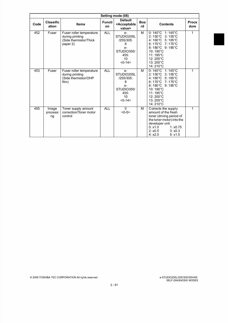
8/9/2019 Service manual E-studio 455
http://slidepdf.com/reader/full/service-manual-e-studio-455 119/670
© 2009 TOSHIBA TEC CORPORATION All rights reserved e-STUDIO205L/255/305/355/455SELF-DIAGNOSIS MODES
2 - 91
452 Fuser Fuser roller temperatureduring printing(Side thermistor/Thickpaper 2)
ALL e-STUDIO205L
/255/305:8e-
STUDIO355/
455:10
<0-14>
M 0: 140°C 1: 145°C2: 150°C 3: 155°C4: 160°C 5: 165°C6: 170°C 7: 175°C8: 180°C 9: 185°C10: 190°C
11: 195°C12: 200°C13: 205°C14: 210°C
1
453 Fuser Fuser roller temperatureduring printing(Side thermistor/OHPfilm)
ALL e-STUDIO205L
/255/305:8e-
STUDIO355/455:10
<0-14>
M 0: 140°C 1: 145°C2: 150°C 3: 155°C4: 160°C 5: 165°C6: 170°C 7: 175°C8: 180°C 9: 185°C10: 190°C11: 195°C12: 200°C13: 205°C14: 210°C
1
455 Imageprocessing
Toner supply amountcorrection/Toner motorcontrol
ALL 0<0-5> M Corrects the supplyamount of the freshtoner (driving period ofthe toner motor) into thedeveloper unit.0: x1.0 1: x0.752: x0.5 3: x0.34: x2.0 5: x1.5
1
Setting mode (08)
CodeClassific
ationItems
Functi
on
Default
<Acceptable
value>
Boa
rdContents
Proce
dure

8/9/2019 Service manual E-studio 455
http://slidepdf.com/reader/full/service-manual-e-studio-455 120/670
e-STUDIO205L/255/305/355/455 © 2009 TOSHIBA TEC CORPORATION All rights reservedSELF-DIAGNOSIS MODES
2 - 92
462 RADF Setting for switchbackoperation in mixed-sizecopying using RADF
ALL 0<0-1>
SYS This setting is whetherthe original length isdetected or not bytransporting withoutscanning in reversewhen A4-R/FOLIO
paper or LT-R/LG paperis detected in a mixed-size copying.0: Disabled - AMS:
A series - Judges as A4-R withouttransporting inreverse with noscanning.LT series - Judgeswhether it is LT-R orLG by its lengthwithout transportingin reverse with no
scanning. APS:
A series - Judgeswhether it is A4-R orFOLIO withouttransporting inreverse with noscanning.LT series - Judgeswhether it is LT-R orLG withouttransporting inreverse with noscanning.
1: Enable 1
AMS: A series - Judgeswhether it is A4-R orFOLIO bytransporting withoutscanning in reverseto detect its length.LT series - Judgeswhether it is LT-R orLG by transportingwithout scanning inreverse to detect itslength.
APS:The same as that of
APS in 0: Disabled.
1
463-0 Paperfeeding
Feedingretry numbersetting(upperdrawer)
Plainpaper
ALL 5<0-5>
M Sets the number oftimes of the feedingretry from the upperdrawer.
4
463-1 Others ALL 5<0-5>
M 4
464-0 Paperfeeding
Feedingretry numbersetting(lowerdrawer)
Plainpaper
ALL 5<0-5>
M Sets the number oftimes of the feedingretry from the lowerdrawer.
4
464-1 Others ALL 5<0-5>
M 4
Setting mode (08)
CodeClassific
ationItems
Functi
on
Default
<Acceptable
value>
Boa
rdContents
Proce
dure

8/9/2019 Service manual E-studio 455
http://slidepdf.com/reader/full/service-manual-e-studio-455 121/670
© 2009 TOSHIBA TEC CORPORATION All rights reserved e-STUDIO205L/255/305/355/455SELF-DIAGNOSIS MODES
2 - 93
465-0 Paperfeeding
Feedingretry numbersetting(PFP upperdrawer)
Plainpaper
ALL 5<0-5>
M Sets the number oftimes of the feedingretry from the PFPupper drawer.
4
465-1 Others ALL 5<0-5>
M 4
466-0 Paper
feeding
Feeding
retry numbersetting(PFP lowerdrawer)
Plain
paper
ALL 5
<0-5>
M Sets the number of
times of the feedingretry from the PFPlower drawer.
4
466-1 Others ALL 5<0-5>
M 4
467-0 Paperfeeding
Feedingretry numbersetting(bypassfeed)
Plainpaper
ALL 5<0-5>
M Sets the number oftimes of the feedingretry from the bypasstray.
4
467-1 Others ALL 5<0-5>
M 4
468-0 Paperfeeding
Feedingretry numbersetting(LCF)
Plainpaper
ALL 5<0-5>
M Sets the number oftimes of the feedingretry from the LCF.
4
468-1 Others ALL 5<0-5>
M 4
471 Paper
feeding
Paper size (Postcard)
feeding/widthwisedirection
ALL 148/100
<148-432/100-297>
M * Postcard is
supported only forJPN model.
10
476-0 Fuser Droppingtemperaturesetting whenprinting onthick paper
First drop ALL e-STUDIO205L
/255/305:1e-
STUDIO355/455:
0<0~10>
M Setting value x 5°C: 0to 50°CThis code is valid onlywhen "20" is set to 08-535-1.
4
476-1 Seconddrop
ALL 2<0~10>
M 4
476-2 Third
drop
ALL e-
STUDIO205L/255/305:
2e-
STUDIO355/455:
3<0~10>
M 4
476-3 Fourthdrop
ALL 3<0~10>
M 4
478 Laser Judged number ofpolygonal motor rotationerror (Normal rotation)
ALL 0<0-1>
M Displays the error[CA10] when the setnumber of rotation errorhas been detected.0: 2 times1: 12 times
1
479 Laser Judged number ofpolygonal motor rotationerror (At acceleration/deceleration)
ALL 0<0-1>
M 0: Time taken from anovershoot occurringto normal valuerange is 0.6 sec.
1: Time taken from anovershoot occurringto normal valuerange is 2.2 sec.
1
Setting mode (08)
CodeClassific
ationItems
Functi
on
Default
<Acceptable
value>
Boa
rdContents
Proce
dure

8/9/2019 Service manual E-studio 455
http://slidepdf.com/reader/full/service-manual-e-studio-455 122/670
e-STUDIO205L/255/305/355/455 © 2009 TOSHIBA TEC CORPORATION All rights reservedSELF-DIAGNOSIS MODES
2 - 94
480 Paperfeeding
Default setting of papersource
PPC 0<0-5>
SYS 0: A4/LT 1: LCF2: Upper drawer 3: Lower drawer 4: PFP upper drawer 5: PFP lower drawer
1
481 Paper
feeding
Automatic change of
paper source
PPC 1
<1-2>
SYS Sets whether or not
changing the drawerautomatically to theother drawer with thepaper of the same sizewhen paper in theselected drawer has runout.1: ON (Changes to the
drawer with thesame paperdirection and size:e.g., A4 to A4)
2: ON (Changes to thedrawer with thesame paper size.Paper with thedifferent direction isacceptable as longas the size is thesame: e.g., A4 to
A4-R, LT-R to LT. “1”is applied when thestaple/hole-punch isspecified.)
1
482 Paperfeeding
Feeding retry setting ALL 0<0-1>
M 0: ON1: OFF
1
483 Laser Pre-running rotation ofpolygonal motor
ALL 0<0-2>
SYS Sets whether or notswitching the polygonalmotor from the standby
rotation to the normalrotation when theoriginal is set on theRADF or the originalcover is opened.0: Valid (when using
RADF and theoriginal is setmanually)
1: Invalid2: Valid (when using
RADF only)
1
484 Laser Polygonal motorrotational statusswitching at the Auto
Clear Mode
ALL 0<0-1>
SYS Sets whether or notswitching the polygonalmotor from the normal
rotation to the standbyrotation at the AutoClear Mode.0: Valid1: Invalid
1
485 Laser Rotational status ofpolygonal motor onstandby
ALL 1<0-1>
SYS Sets the rotationalstatus of polygonalmotor on standby.0: Rotated (The
rotational speed isset at 08-490.)
1: Stopped
1
Setting mode (08)
CodeClassific
ationItems
Functi
on
Default
<Acceptable
value>
Boa
rdContents
Proce
dure

8/9/2019 Service manual E-studio 455
http://slidepdf.com/reader/full/service-manual-e-studio-455 123/670
© 2009 TOSHIBA TEC CORPORATION All rights reserved e-STUDIO205L/255/305/355/455SELF-DIAGNOSIS MODES
2 - 95
486 Laser Timing of auto-clearingof polygonal motor pre-running rotation
ALL 3<0-6>
SYS Switches the polygonalmotor to the standbyrotation when a certainperiod of time haspassed from the pre-running. At this code,
the period to switch thestatus to the standbyrotation is set.0: 15 sec.1: 20 sec.2: 25 sec.3: 30 sec.4: 35 sec.5: 40 sec.6: 45 sec.* This setting is
effective when “0” or“2” is set at 08-483.
1
488 Laser Setting of polygonalmotor type
ALL 3<0-3>
M Set the type ofpolygonal motor.0: 2-clock type1: 3-clock type2: 4-clock type3: 6-clock type
1
489 Laser Polygonal motor rotationnumber on standby
ALL 5<0-5>
M 0: 38,090.55 rpm1: 35,000 rpm2: 30,000 rpm3: 25,000 rpm4: 20,000 rpm5: 10,000 rpm
1
490 Laser Polygonal motor rotationin the energy savingmode
ALL 0<0-1>
M 0: Stopped1: 10,000 rpm
1
491 Transfer Transfer charger bias
correction (H) atduplexing
ALL 126
<0-255>
M Corrects the transfer
charger bias outputvalue of the leadingedge area of paper atduplexing.
1
492 Transfer Transfer charger biascorrection (C) atduplexing
ALL e-STUDIO205L
/255/305:124e-
STUDIO355/455:123
<0-255>
M Corrects the transfercharger bias outputvalue of the center areaof paper at duplexing.
1
493 Transfer Transfer charger bias
correction (L) atduplexing
ALL e-
STUDIO205L/255/305:118e-
STUDIO355/455:112
<0-255>
M Corrects the transfer
charger bias outputvalue of the trailingedge area of paper atduplexing.
1
Setting mode (08)
CodeClassific
ationItems
Functi
on
Default
<Acceptable
value>
Boa
rdContents
Proce
dure

8/9/2019 Service manual E-studio 455
http://slidepdf.com/reader/full/service-manual-e-studio-455 124/670
e-STUDIO205L/255/305/355/455 © 2009 TOSHIBA TEC CORPORATION All rights reservedSELF-DIAGNOSIS MODES
2 - 96
499 Imageprocessi
ng
Toner cartridge (K)sensor detection level
ALL AUD/TWD: 1JPD/NAD/MJD/SAD/
ASU/ASD/CND/KRD/ ARD: 2
<0-2>
M 0: Level 0 (Nodetection)
1: Level 1 (Warningnotification)
2: Level 3 (Stopprinting)
1
502 Image Error diffusion and dithersetting at photo mode
PPC 1<0-1>
SYS Sets the imagereproduction method atphoto mode.0: Error diffusion1: Dither
1
503 Userinterface
Default setting of densityadjustment
PPC 0<0-1>
SYS 0: Automatic1: Manual (Center)
1
508 Image Custom Mode setting PPC 0<0-3>
SYS 0: Not used1: Text/Photo is set as
a base2: Text is set as a base3: Photo is set as a
base
1
509 Image Error diffusion and dithersetting at a photo mode(Custom Mode)
PPC 1<0-1>
SYS Switches the imageprocessing methodwhen Custom Mode 3is set.0: Error diffusion1: Dither
1
515 Fuser Temperature setting ofwarming-up(Center thermistor)
ALL e-STUDIO205L
/255/305:4e-
STUDIO355/455:
8<0-14>
M 0: 140°C 1: 145°C2: 150°C 3: 155°C4: 160°C 5: 165°C6: 170°C 7: 175°C8: 180°C 9: 185°C10: 190°C11: 195°C12: 200°C13: 205°C
14: 210°C
1
516 Fuser Temperature setting ofwarming-up(Side thermistor)
ALL e-STUDIO205L
/255/305:4e-
STUDIO355/455:
8<0-14>
M 0: 140°C 1: 145°C2: 150°C 3: 155°C4: 160°C 5: 165°C6: 170°C 7: 175°C8: 180°C 9: 185°C10: 190°C11: 195°C12: 200°C13: 205°C14: 210°C
1
Setting mode (08)
CodeClassific
ationItems
Functi
on
Default
<Acceptable
value>
Boa
rdContents
Proce
dure

8/9/2019 Service manual E-studio 455
http://slidepdf.com/reader/full/service-manual-e-studio-455 125/670
© 2009 TOSHIBA TEC CORPORATION All rights reserved e-STUDIO205L/255/305/355/455SELF-DIAGNOSIS MODES
2 - 97
517 Fuser Pre-running time(Normal temperature)
ALL 3<0-18>
M 0: Disabled1: 1 sec.2: 2 sec.3: 3 sec.4: 4 sec.5: 5 sec.
6: 6 sec.7: 7 sec.8: 8 sec.9: 9 sec.10: 10 sec.11: 15 sec.12: 20 sec.13: 25 sec.14: 30 sec.15: 40 sec.16: 50 sec.17: 60 sec.18: 150 sec.
1
518 Fuser Fuser roller temperatureduring printing(Side thermistor/Thickpaper 3)
ALL e-STUDIO205L
/255/305:8e-
STUDIO355/455:10
<0-14>
M 0: 140°C 1: 145°C2: 150°C 3: 155°C4: 160°C 5: 165°C6: 170°C 7: 175°C8: 180°C 9: 185°C10: 190°C11: 195°C12: 200°C13: 205°C14: 210°C
1
520 Fuser Fuser roller temperatureduring printing(Center thermistor/Envelope)
ALL e-STUDIO205L
/255/305:11e-
STUDIO355/
455:13<0-14>
M 0: 140°C 1: 145°C2: 150°C 3: 155°C4: 160°C 5: 165°C6: 170°C 7: 175°C8: 180°C 9: 185°C10: 190°C
11: 195°C12: 200°C13: 205°C14: 210°C
1
521 Fuser Fuser roller temperatureduring printing(Side thermistor/Envelope)
ALL e-STUDIO205L
/255/305:9e-
STUDIO355/455:11
<0-14>
M 0: 140°C 1: 145°C2: 150°C 3: 155°C4: 160°C 5: 165°C6: 170°C 7: 175°C8: 180°C 9: 185°C10: 190°C11: 195°C12: 200°C13: 205°C14: 210°C
1
523 Fuser Pre-running time for first
printing(Envelope)
ALL 10
<0-15>
M 0: Invalid 1: 1 sec.
2: 2 sec. 3: 3 sec.4: 4 sec. 5: 5 sec.6: 6 sec. 7: 7 sec.8: 8 sec. 9: 9 sec.10: 10 sec.11: 12 sec.12: 14 sec.13: 16 sec.14: 18 sec.15: 20 sec.
1
Setting mode (08)
CodeClassific
ationItems
Functi
on
Default
<Acceptable
value>
Boa
rdContents
Proce
dure

8/9/2019 Service manual E-studio 455
http://slidepdf.com/reader/full/service-manual-e-studio-455 126/670
e-STUDIO205L/255/305/355/455 © 2009 TOSHIBA TEC CORPORATION All rights reservedSELF-DIAGNOSIS MODES
2 - 98
525-0 Fuser Temperaturedropswitchingtime settingduringprinting
(Centerthermistor)
The firstdrop
ALL e-STUDIO205L
/255/305:20e-
STUDIO355/
455:10
<0-200>
M Setting value x 5 sec.:from 0 to 1,000 sec.later This code is valid onlywhen "20" is set to 08-535-0.
4
525-1 Theseconddrop
ALL e-STUDIO205L
/255/305:30e-
STUDIO355/455:18
<0-200>
M 4
525-2 The thirddrop
ALL e-STUDIO205L
/255/305:40e-
STUDIO355/455:24
<0-200>
M 4
525-3 Thefourthdrop
ALL 75<0-200>
M 4
526 Fuser Pre-running time for firstprinting (OHP film)
ALL 0<0-15>
M 0: Invalid 1: 0 sec.2: 2 sec. 3: 3 sec.4: 4 sec. 5: 5 sec.6: 6 sec. 7: 7 sec.8: 8 sec. 9: 9 sec.
10: 10 sec.11: 12 sec.12: 14 sec.13: 16 sec.14: 18 sec.15: 20 sec.
1
Setting mode (08)
CodeClassific
ationItems
Functi
on
Default
<Acceptable
value>
Boa
rdContents
Proce
dure

8/9/2019 Service manual E-studio 455
http://slidepdf.com/reader/full/service-manual-e-studio-455 127/670
© 2009 TOSHIBA TEC CORPORATION All rights reserved e-STUDIO205L/255/305/355/455SELF-DIAGNOSIS MODES
2 - 99
527-0 Fuser Temperaturedropswitchingtime settingduringprinting
(Sidethermistor)
The firstdrop
ALL e-STUDIO205L
/255/305:20e-
STUDIO355/
455:10
<0-200>
M Setting value x 5 sec.:from 0 to 1,000 sec.later This code is valid onlywhen "20" is set to 08-535-0.
4
527-1 Theseconddrop
ALL e-STUDIO205L
/255/305:30e-
STUDIO355/455:18
<0-200>
M 4
527-2 The thirddrop
ALL e-STUDIO205L
/255/305:40e-
STUDIO355/455:24
<0-200>
M 4
527-3 Thefourthdrop
ALL 75<0-200>
M 4
535-0 Fuser Temperature dropcontrol setting duringprinting(Temperature/Time)
ALL 2<0-20>
M 0: None1: Pattern 12: Pattern 23: Pattern 34: Pattern 4
5: Pattern 56: Pattern 67: Pattern 78: Pattern 89: Pattern 910: Pattern 1011: Pattern 1112: Pattern 1213: Pattern 1314: Pattern 1415: Pattern 1516: Pattern 1617: Pattern 1718: Pattern 1819: Pattern 19
20: Manual adjustment
4
Setting mode (08)
CodeClassific
ationItems
Functi
on
Default
<Acceptable
value>
Boa
rdContents
Proce
dure

8/9/2019 Service manual E-studio 455
http://slidepdf.com/reader/full/service-manual-e-studio-455 128/670
e-STUDIO205L/255/305/355/455 © 2009 TOSHIBA TEC CORPORATION All rights reservedSELF-DIAGNOSIS MODES
2 - 100
535-1 Fuser Temperature dropcontrol setting duringprinting(Temperature/Time)
ALL 2<0-20>
M 0: None1: Pattern 12: Pattern 23: Pattern 34: Pattern 45: Pattern 5
6: Pattern 67: Pattern 78: Pattern 89: Pattern 910: Pattern 1011: Pattern 1112: Pattern 1213: Pattern 1314: Pattern 1415: Pattern 1516: Pattern 1617: Pattern 1718: Pattern 1819: Pattern 1920: Manual adjustment
4
536-0 Fuser Temperaturedrop settingduringprinting(Centerthermistor)
The firstdrop
ALL e-STUDIO205L
/255/305:1e-
STUDIO355/455:
0<0-10>
M Setting value x -5°C:from 0°C to -50°CThis code is valid onlywhen "20" is set to 08-535-0.
4
536-1 Theseconddrop
ALL 2<0-10>
M 4
536-2 The thirddrop
ALL e-STUDIO205L
/255/305:2e-
STUDIO355/455:
3<0-10>
M 4
536-3 Thefourthdrop
ALL 3<0-10>
M 4
Setting mode (08)
CodeClassific
ationItems
Functi
on
Default
<Acceptable
value>
Boa
rdContents
Proce
dure

8/9/2019 Service manual E-studio 455
http://slidepdf.com/reader/full/service-manual-e-studio-455 129/670
© 2009 TOSHIBA TEC CORPORATION All rights reserved e-STUDIO205L/255/305/355/455SELF-DIAGNOSIS MODES
2 - 101
537-0 Fuser Temperaturedrop settingduringprinting(Sidethermistor)
The firstdrop
ALL e-STUDIO205L
/255/305:2e-
STUDIO355/
455:4
<0-10>
M Setting value x -5°C:from 0°C to -50°CThis code is valid onlywhen "20" is set to 08-535-0.
4
537-1 Theseconddrop
ALL e-STUDIO205L
/255/305:3e-
STUDIO355/455:
6<0-10>
M 4
537-2 The thirddrop
ALL e-STUDIO205L
/255/305:4e-
STUDIO355/455:
6<0-10>
M 4
537-3 Thefourthdrop
ALL e-STUDIO205L
/255/305:5e-
STUDIO355/455:
6
<0-10>
M 4
Setting mode (08)
CodeClassific
ationItems
Functi
on
Default
<Acceptable
value>
Boa
rdContents
Proce
dure

8/9/2019 Service manual E-studio 455
http://slidepdf.com/reader/full/service-manual-e-studio-455 130/670
e-STUDIO205L/255/305/355/455 © 2009 TOSHIBA TEC CORPORATION All rights reservedSELF-DIAGNOSIS MODES
2 - 102
539-0 Fuser Temperaturedrop settingduringprinting onthick paper (Side
thermistor)
The firstdrop
ALL e-STUDIO205L
/255/305:2e-
STUDIO355/
455:4
<0-10>
M Setting value x -5°C:from 0°C to -50°CThis code is valid onlywhen "20" is set to 08-535-1.
4
539-1 Theseconddrop
ALL e-STUDIO205L
/255/305:3e-
STUDIO355/455:
6<0-10>
M 4
539-2 The thirddrop
ALL e-STUDIO205L
/255/305:4e-
STUDIO355/455:
6<0-10>
M 4
539-3 Thefourthdrop
ALL e-STUDIO205L
/255/305:5e-
STUDIO355/455:
6
<0-10>
M 4
Setting mode (08)
CodeClassific
ationItems
Functi
on
Default
<Acceptable
value>
Boa
rdContents
Proce
dure

8/9/2019 Service manual E-studio 455
http://slidepdf.com/reader/full/service-manual-e-studio-455 131/670
© 2009 TOSHIBA TEC CORPORATION All rights reserved e-STUDIO205L/255/305/355/455SELF-DIAGNOSIS MODES
2 - 103
540-0 Fuser Temperaturedropswitchingtime settingduringprinting on
thick paper (Centerthermistor)
The firstdrop
ALL e-STUDIO205L
/255/305:20e-
STUDIO355/
455:10
<0-200>
M Setting value x 5seconds: from 0 to1000 secondsThis code is valid onlywhen "20" is set to 08-535-1.
4
540-1 Theseconddrop
ALL e-STUDIO205L
/255/305:30e-
STUDIO355/455:18
<0-200>
M 4
540-2 The thirddrop
ALL e-STUDIO205L
/255/305:40e-
STUDIO355/455:24
<0-200>
M 4
540-3 Thefourthdrop
ALL 75<0-200>
M 4
541-0 Fuser Temperaturedropswitchingtime settingduring
printing onthick paper (Sidethermistor)
The firstdrop
ALL e-STUDIO205L
/255/305:20e-
STUDIO355/455:10
<0-200>
M Setting value x 5seconds: from 0 to1000 secondsThis code is valid onlywhen "20" is set to 08-
535-1.
4
541-1 Theseconddrop
ALL e-STUDIO205L
/255/305:30e-
STUDIO355/455:18
<0-200>
M 4
541-2 The third
drop
ALL e-
STUDIO205L/255/305:40e-
STUDIO355/455:24
<0-200>
M 4
541-3 Thefourthdrop
ALL 75<0-200>
M 4
Setting mode (08)
CodeClassific
ationItems
Functi
on
Default
<Acceptable
value>
Boa
rdContents
Proce
dure

8/9/2019 Service manual E-studio 455
http://slidepdf.com/reader/full/service-manual-e-studio-455 132/670
e-STUDIO205L/255/305/355/455 © 2009 TOSHIBA TEC CORPORATION All rights reservedSELF-DIAGNOSIS MODES
2 - 104
550 Image Default setting of originalmode
PPC 0<0-5>
SYS 0: Standard1: Text2: Photo3: Not used(nonenterable)4: Custom
5: Color documentmode
1
580 Userinterface
User custom modesetting
SCN(black)
0<0-3>
SYS 0: Unused1: B/W TEXT/PHOTO
base2: B/W TEXT base3: B/W PHOTO base
1
590 Userinterface
User custom modesetting
SCN(color)
0<0-4>
SYS 0: Unused1: TEXT base2: Printed image base3: Photo base4: e-document base
1
602 Userinterface
Screen setting for Autopower Save Mode and
Auto Shut OFF Mode
ALL EUR: 0UC: 1
JPN: 1<0-1>
SYS 0: OFF 1: ON 1
603 Userinterface
Setting for automaticduplexing mode
PPC 0<0-3>
SYS 0: Invalid1: Single-sided to
duplex copying2: Double-sided to
duplex copying3: User selection
1
604 Userinterface
Default setting for APS/ AMS
PPC 0<0-2>
SYS 0: APS (AutomaticPaper Selection)
1: AMS (AutomaticMagnificationSelection)
2: Not selected
1
605 Userinterface
Centering printing ofprimary/secondarydirection at AMS
PPC 1<0-1>
SYS 0: Invalid 1: Valid 1
607 Userinterface
Default setting of RADFmode
PPC 0<0-1>
SYS 0: Continuous feeding(by pressing the[START] button)
1: Single feeding(by setting originalon the tray)
1
610 Userinterface
Key touch sound ofcontrol panel
ALL 1<0-1>
SYS 0: OFF1: ON
1
611 Userinterface
Book type originalpriority
PPC 0<0-1>
SYS 0: Left page to rightpage
1: Right page to leftpage
1
613 Userinterface
Paper size selection for[OTHER] button
PPC EUR:FOLIO
UC:COMP
JPN: A5-R
SYS Press the button on theLCD to select the size.
9
Setting mode (08)
CodeClassific
ationItems
Functi
on
Default
<Acceptable
value>
Boa
rdContents
Proce
dure

8/9/2019 Service manual E-studio 455
http://slidepdf.com/reader/full/service-manual-e-studio-455 133/670
© 2009 TOSHIBA TEC CORPORATION All rights reserved e-STUDIO205L/255/305/355/455SELF-DIAGNOSIS MODES
2 - 105
614 Network Local I/F time-out period PRT 6<1-50>
SYS Sets the period of timewhen the job is judgedas completed in local I/F printing (USB orparallel).1: 1.0 sec.
2: 1.5 sec.-50: 25.5 sec.(in increments of 0.5sec.)
1
617 Userinterface
Printing/PC-FAX settingwithout department codeor registration code
ALL 1<0-2>
SYS 0: Printed1: Not printed (pooled
in the invalid queue)2: Deleted forcibly
1
618 Userinterface
Default setting whenmixed size originals areset
PPC 0<0-1>
SYS 0: Scanned as all insame size
1: Scanned as eachoriginal size
1
619 Paperfeeding
Time lag before Auto JobStart of bypass feeding
ALL 4<0-10>
SYS Sets the time taken toadd paper feeding
when paper in thebypass tray has run outduring the bypass feedcopying.0: Paper is not drawn
in unless the[START] button ispressed.
1-10: Setting value x0.5 sec.
1
620 Userinterface
Departmentmanagement setting(Copier)
PPC 1<0-1>
SYS 0: Invalid1: Valid
1
621 Userinterface
Departmentmanagement setting
(FAX)
FAX 1<0-1>
SYS 0: Invalid1: Valid
1
622 Userinterface
Departmentmanagement setting(Printer)
PRT 1<0-1>
SYS 0: Invalid1: Valid
1
623 Userinterface
Departmentmanagement setting(Scanner)
SCN 1<0-1>
SYS 0: Invalid1: Valid
1
624 Userinterface
Departmentmanagement setting(List print)
PRT 1<0-1>
SYS 0: Invalid1: Valid
1
625 Userinterface
Blank copyingprevention mode duringRADF jamming
PPC 0<0-1>
SYS 0: OFF1: ON (Start printing
when the scanningof each page is
finished)
1
627 Userinterface
Rotation printing at thenon-sorting
ALL 0<0-1>
SYS 0: Not rotating1: Rotating
1
628 Userinterface
Direction priority oforiginal image
PPC 0<0-1>
SYS 0: Automatic1: Portrait
1
629 Userinterface
Departmentmanagement setting
ALL 0<0-1>
SYS 0: Invalid1: Valid
1
634 Userinterface
Inner receiving traypriority at Non-sort Mode
ALL 0<0-1>
SYS 0: Normal1: Inner receiving tray
1
636 Userinterface
Width setting for imageshift copying (linkage offront side and back side)
PPC 0<0-1>
SYS 0: ON1: OFF
1
Setting mode (08)
CodeClassific
ationItems
Functi
on
Default
<Acceptable
value>
Boa
rdContents
Proce
dure

8/9/2019 Service manual E-studio 455
http://slidepdf.com/reader/full/service-manual-e-studio-455 134/670
e-STUDIO205L/255/305/355/455 © 2009 TOSHIBA TEC CORPORATION All rights reservedSELF-DIAGNOSIS MODES
2 - 106
638 General Time differences ALL EUR: 24UC: 40JPN: 6<0-47>
SYS 0: +12.0h 1: +11.5h2: +11.0h 3: +10.5h4: +10.0h 5: +9.5h6: +9.0h 7: +8.5h8: +8.0h 9: +7.5h10: +7.0h 11: +6.5h
12: +6.0h 13: +5.5h14: +5.0h 15: +4.5h16: +4.0h 17: +3.5h18: +3.0h 19: +2.5h20: +2.0h 21: +1.5h22: +1.0h 23: +0.5h24: 0.0h 25: -0.5h26: -1.0h 27: -1.5h28: -2.0h 29: -2.5h30: -3.0h 31: -3.5h32: -4.0h 33: -4.5h34: -5.0h 35: -5.5h36: -6.0h 37: -6.5h38: -7.0h 39: -7.5h40: -8.0h 41: -8.5h
42: -9.0h 43: -9.5h44: -10.0h45: -10.5h46: -11.0h47: -11.5h
1
640 Userinterface
Date display format ALL EUR: 1UC: 2JPN: 0<0-2>
SYS 0: YYYY.MM.DD.1: DD.MM.YYYY2: MM.DD.YYYY
1
641 Userinterface
Automatic Sorting Modesetting (RADF)
PPC 2<0-4>
SYS 0: Invalid 1: STAPLE2: SORT 3: GROUP4: ROTATE SORT
1
642 Userinterface
Default setting of SorterMode
PPC 0<0-4>
SYS 0: NON-SORT1: STAPLE
2: SORT 3: GROUP4: ROTATE SORT
1
645 Userinterface
Correction ofreproduction ratio inediting copy
PPC 10<0-10>
SYS Sets the reproductionratio for the “X in 1”printing (includingmagazine sort) to the“Reproduction ratio xCorrection ratio”.0: 90% 1: 91%2: 92% 3: 93%4: 94% 5: 95%6: 96% 7: 97%8: 98% 9: 99%10: 100%
1
646 Userinterface
Image position in editing PPC 2<0-3>
SYS Sets the page pastedposition for “X in 1” tothe upper left corner/center.0: PPC:Cornering/
PRT:Cornering1: PPC:Centering/
PRT:Cornering2: PPC:Cornering/
PRT:Centering3: PPC:Centering/
PRT:Centering
1
Setting mode (08)
CodeClassific
ationItems
Functi
on
Default
<Acceptable
value>
Boa
rdContents
Proce
dure

8/9/2019 Service manual E-studio 455
http://slidepdf.com/reader/full/service-manual-e-studio-455 135/670
© 2009 TOSHIBA TEC CORPORATION All rights reserved e-STUDIO205L/255/305/355/455SELF-DIAGNOSIS MODES
2 - 107
648 Userinterface
Returning finisher traywhen printing is finished
ALL 0<0-1>
SYS Sets whether or notreturning the finishertray to the bin 1 whenprinting is finished.0: Not returned1: Returned
1
649 Userinterface
Magazine sort setting PPC 0<0-1>
SYS 0: Left page to rightpage
1: Right page to leftpage
1
650 Userinterface
2 in 1/4 in 1 pageallocating order setting
PPC 0<0-1>
SYS 0: Horizontal1: Vertical
1
651 Userinterface
Printing format settingfor Time stamp andPage Number
PPC 2<0-3>
SYS Hyphen(with page number)/Dropout (with date, time andpage number)0: OFF/OFF1: ON/OFF2: OFF/ON
3: ON/ONNote:
Hyphen printingformatON: -1- OFF: 1
1
652 Userinterface
Cascade operationsetting
PPC 0<0-1>
SYS 0: OFF1: ON2: ON (Circulation)
1
653 Userinterface
Cascade operationsetting
PRT 0<0-2>
SYS 0: OFF1: ON (STOP)2: ON (Circulation)
1
657 Userinterface
Direction priority for dateand time stamp printing
PPC 0<0-1>
SYS 0: Short edge1: Long edge
1
658 User
interface
Auto Job Start setting for
bypass feed printing
PRT 0
<0-1>
SYS Sets whether or not
feeding a paperautomatically into theequipment when it isplaced on the bypasstray.0: OFF (Press the
[START] button tostart feeding.)
1: ON (Automaticfeeding)
1
659 Userinterface
Auto Job start setting forbypass feed printing
PPC 1<0-1>
SYS Sets whether or notfeeding a paperautomatically into theequipment when it isplaced on the bypass
tray.0: OFF (Press the
[START] button tostart feeding.)
1: ON (Automaticfeeding)
1
660 Network Auto-forwarding settingof received FAX
ALL 0<0-1>
SYS 0: Invalid1: Valid
1
661 Network Auto-forwarding settingof received E-mail
ALL 0<0-1>
SYS 0: Invalid1: Valid
1
Setting mode (08)
CodeClassific
ationItems
Functi
on
Default
<Acceptable
value>
Boa
rdContents
Proce
dure

8/9/2019 Service manual E-studio 455
http://slidepdf.com/reader/full/service-manual-e-studio-455 136/670

8/9/2019 Service manual E-studio 455
http://slidepdf.com/reader/full/service-manual-e-studio-455 137/670
© 2009 TOSHIBA TEC CORPORATION All rights reserved e-STUDIO205L/255/305/355/455SELF-DIAGNOSIS MODES
2 - 109
681 General Display of [BANNERMESSAGE] button
ALL 0<0-1>
SYS 0: Not displayed1: Displayed* This button enables
the entry of “Banneradvertising display 1(08-679)” and
“Banner advertisingdisplay 2 (08-680)”on the control panel.
1
683 General Duplex printing settingwhen coin controller isused
ALL 1<0-1>
SYS When the duplexprinting is short paidwith a coin controller,reverse side of theoriginal is not printedand is considered as adefect (printing job maybe cleared). To solvethis problem, theselection of printingmethod is enabled withthis setting.0: Invalid (Both sides
printed)1: Valid (Only one side
printed)
1
684 General Rebuilding all databases ALL - SYS Rebuilds all databases. 3
685 General Rebuilding all databasesrelated to address book
ALL - SYS Rebuilds all databasesrelated to the AddressBook. (Address book,template, extension, Fcode, and transmissionsetting when Fax/Internet Fax jobreceived)
3
686 General Rebuilding all databases
related to log
ALL - SYS Rebuilds all databases
related to the log. (Joblog and message log)
3
689 FAX Adaptation of papersource priority selection
FAX 0<0-1>
SYS 0: Not subjected for APS judgment
1: Subjected for APS judgment
1
690 General HDD formatting ALL 2<2>
SYS 0: Not formatted2: Normal formatting
7
691 General HDD type display ALL -<0, 2>
SYS 0: Not formatted2: Formatted with DSI
type
7
692 Maintenance
Performing panelcalibration
ALL - SYS Performs the calibrationof the pressing positionon the touch panel
(LCD screen). Thecalibration is performedby pressing 2 referencepositions after this codeis started up.
1
693 General Initialization of NICinformation
ALL - SYS Returns the value to thefactory shipping defaultvalue.
3
694 General Performing HDD testing ALL - SYS Checks the bad sector. 3
695 General Notifying condition oftrial period end
PRT/SCN
3<0-255>
SYS Sets when the end oftrial period is notified.0: On the day it ends1 to 255: n days before
1
Setting mode (08)
CodeClassific
ationItems
Functi
on
Default
<Acceptable
value>
Boa
rdContents
Proce
dure

8/9/2019 Service manual E-studio 455
http://slidepdf.com/reader/full/service-manual-e-studio-455 138/670

8/9/2019 Service manual E-studio 455
http://slidepdf.com/reader/full/service-manual-e-studio-455 139/670
© 2009 TOSHIBA TEC CORPORATION All rights reserved e-STUDIO205L/255/305/355/455SELF-DIAGNOSIS MODES
2 - 111
716 Maintenance
Remote-controlledserviceWriting data of self-diagnostic code
ALL 0<0-1>
SYS 0: Prohibited1: Accepted
1
717 Maintenance
Remote-controlledservice response waiting
time(Timeout)
ALL 3<1-30>
SYS Unit: Minute 1
718 Maintenance
Remote-controlledservice initial registration
ALL 0<0-3>
SYS 0: OFF1: Start2: Only certification is
scanned3: Satellite
communiction starts
1
719 Maintenance
Remote-controlledservice tentativepassword
ALL - SYS Maximum 10 letters 11
720 Maintenance
Status of remote-controlled service initialregistration
(Display only)
ALL 0<0-1>
SYS 0: Not registered1: Registered
2
721 Maintenance
Service center callfunction
ALL 2<0-2>
SYS 0: OFF1: Notifies all service
calls2: Notifies all but
paper jams
1
723 Maintenance
Service center callHTTP server URLsetting
ALL - SYS Maximum 256 letters 11
726 Maintenance
HTTP proxy setting ALL 1<0-1>
SYS 0: Valid1: Invalid
1
727 Maintenance
HTTP proxy IP addresssetting
ALL - SYS 000.000.000.000-255.255.255.255(Default value
000.000.000.000)
11
728 Maintenance
HTTP proxy port numbersetting
ALL 0<0-65535>
SYS 1
729 Maintenance
HTTP proxy ID setting ALL - SYS Maximum 30 letters 11
730 Maintenance
HTTP proxy passwordsetting
ALL - SYS Maximum 30 letters 11
731 Maintenance
HTTP proxy paneldisplay
ALL 1<0-1>
SYS 0: Valid1: Invalid
1
732 Maintenance
Automatic orderingfunction of supplies
ALL 3<0-3>
SYS 0: Ordered by FAX1: Ordered by E-mail2: Ordered by HTTP3: OFF
1
733 Maintena
nce
Automatic ordering
function of suppliesFAX number
ALL - SYS Maximum 32 digits
Enter hyphen with the[Pause] button
11
734 Maintenance
Automatic orderingfunction of suppliesE-mail address
ALL - SYS Maximum 192 lettersList: 256 digits
11
738 Maintenance
(Remote)
Automatic orderingfunction of suppliesUser's name
ALL - SYS Maximum 50 letters 11
739 Maintenance
(Remote)
Automatic orderingfunction of suppliesUser's telephonenumber
ALL - SYS Maximum 32 digitsEnter hyphen with the[Pause] button
11
Setting mode (08)
CodeClassific
ationItems
Functi
on
Default
<Acceptable
value>
Boa
rdContents
Proce
dure

8/9/2019 Service manual E-studio 455
http://slidepdf.com/reader/full/service-manual-e-studio-455 140/670
e-STUDIO205L/255/305/355/455 © 2009 TOSHIBA TEC CORPORATION All rights reservedSELF-DIAGNOSIS MODES
2 - 112
740 Maintenance
(Remote)
Automatic orderingfunction of suppliesUser's E-mail address
ALL - SYS Maximum 192 lettersList: 256 digits
11
741 Maintenance
(Remote)
Automatic orderingfunction of suppliesUser's address
ALL - SYS Maximum 100 letters 11
742 Maintenance
(Remote)
Automatic orderingfunction of suppliesService number
ALL - SYS Maximum 5 digits 11
743 Maintenance
(Remote)
Automatic orderingfunction of suppliesService technician'sname
ALL - SYS Maximum 50 letters 11
744 Maintenance
(Remote)
Automatic orderingfunction of suppliesService technician'stelephone number
ALL - SYS Maximum 32 digitsEnter hyphen with the[Pause] button
11
745 Maintenance
(Remote)
Automatic orderingfunction of suppliesService technician's E-
mail address
ALL - SYS Maximum 192 lettersList: 256 digits
11
746 Maintenance
(Remote)
Automatic orderingfunction of suppliesSupplier's name
ALL - SYS Maximum 50 letters 11
747 Maintenance
(Remote)
Automatic orderingfunction of suppliesSupplier's address
ALL - SYS Maximum 100 letters 11
748 Maintenance
(Remote)
Automatic orderingfunction of suppliesNotes
ALL - SYS Maximum 128 letters 11
758 Maintenance
(Remote)
Information aboutsuppliesPart number of tonercartridge
ALL - SYS Maximum 20 digits 11
759 Maintenance
(Remote)
Information aboutsuppliesOrder quantity of tonercartridge
ALL 1<1-99>
SYS 1
760 Maintenance
(Remote)
Information aboutsuppliesCondition number oftoner cartridge
ALL 1<1-99>
SYS 1
761 Maintenance
(Remote)
Information aboutsuppliesPart number of wastetoner box
ALL - SYS Maximum 20 digits 11
762 Maintenance
(Remote)
Information aboutsupplies
Order quantity of wastetoner box
ALL 1<1-99>
SYS 1
763 Maintenance
(Remote)
Information aboutsuppliesCondition number ofwaste toner box
ALL 1<1-99>
SYS 1
765 Maintenance
(Remote)
Automatic orderingsuppliesDisplay
ALL EUR: 2UC: 0JPN: 2<0-2>
SYS 0: Valid (FAX/InternetFAX)
1: Valid (FAX/InternetFAX/HTTP)
2: Invalid
1
Setting mode (08)
CodeClassific
ationItems
Functi
on
Default
<Acceptable
value>
Boa
rdContents
Proce
dure

8/9/2019 Service manual E-studio 455
http://slidepdf.com/reader/full/service-manual-e-studio-455 141/670
© 2009 TOSHIBA TEC CORPORATION All rights reserved e-STUDIO205L/255/305/355/455SELF-DIAGNOSIS MODES
2 - 113
767 Maintenance
(Remote)
Service Notificationsetting
ALL 0<0-2>
SYS Enables to set up to 3E-mail addresses to besent.(08-768, 777, 778)0: Invalid1: Valid (E-mail)2: Valid (FAX)
1
768 Maintenance
(Remote)
Destination E-mailaddress 1
ALL - SYS Maximum 192 letters 11
769 Maintenance
(Remote)
Total counter informationtransmission setting
ALL 0<0-1>
SYS 0: Invalid1: Valid
1
770 Maintenance
(Remote)
Total countertransmission date setting
ALL 0<0-31>
SYS 0 to 31 1
771 Maintenance
(Remote)
PM counter notificationsetting
ALL 0<0-1>
SYS 0: Invalid1: Valid
1
772 Maintenance
Dealer's name ALL - SYS Maximum 100 lettersNeeded at initial
registration
11
773 Maintenance
Login name ALL - SYS Maximum 20 lettersNeeded at initialregistration
11
774 Maintenance
(Remote)
Display setting of[Service Notification]button
ALL EUR: 0UC: 1JPN: 0<0-1>
SYS 0: Not displayed1: displayed
1
775 Maintenance
(Remote)
Sending error history ofequipment
ALL 0<0-1>
SYS 0: Invalid1: Valid
1
776 Maintenance
(Remote)
Setting total countertransmission interval
ALL - SYS (Hour/Hour/Minute/Minute)
1
777 Maintenance
(Remote)
Destination E-mailaddress 2
ALL - SYS Maximum 192 letters 11
778 Maintenance
(Remote)
Destination E-mailaddress 3
ALL - SYS Maximum 192 letters 11
780 Maintenance
Remote-controlledservice polling dayselectionDay-1
ALL 0<0-31>
SYS 0: OFF1 to 31: 1st to 31st of amonth
1
781 Maintenance
Remote-controlledservice polling dayselectionDay-2
ALL 0<0-31>
SYS 0: OFF1 to 31: 1st to 31st of amonth
1
782 Maintenance
Remote-controlledservice polling dayselectionDay-3
ALL 0<0-31>
SYS 0: OFF1 to 31: 1st to 31st of amonth
1
783 Maintenance
Remote-controlledservice polling dayselectionDay-4
ALL 0<0-31>
SYS 0: OFF1 to 31: 1st to 31st of amonth
1
784 Maintenance
Remote-controlledservice polling dayselectionSunday
ALL 0<0-1>
SYS 0: Invalid1: Valid
1
Setting mode (08)
CodeClassific
ationItems
Functi
on
Default
<Acceptable
value>
Boa
rdContents
Proce
dure

8/9/2019 Service manual E-studio 455
http://slidepdf.com/reader/full/service-manual-e-studio-455 142/670
e-STUDIO205L/255/305/355/455 © 2009 TOSHIBA TEC CORPORATION All rights reservedSELF-DIAGNOSIS MODES
2 - 114
785 Maintenance
Remote-controlledservice polling dayselectionMonday
ALL 0<0-1>
SYS 0: Invalid1: Valid
1
786 Maintenance
Remote-controlledservice polling day
selectionTuesday
ALL 0<0-1>
SYS 0: Invalid1: Valid
1
787 Maintenance
Remote-controlledservice polling dayselectionWednesday
ALL 0<0-1>
SYS 0: Invalid1: Valid
1
788 Maintenance
Remote-controlledservice polling dayselectionThursday
ALL 0<0-1>
SYS 0: Invalid1: Valid
1
789 Maintenance
Remote-controlledservice polling dayselectionFriday
ALL 0<0-1>
SYS 0: Invalid1: Valid
1
790 Maintenance
Remote-controlledservice polling dayselectionSaturday
ALL 0<0-1>
SYS 0: Invalid1: Valid
1
794 Maintenance
Information of suppliessetting of toner cartridgeK
ALL 0<0-1>
SYS 0: Invalid1: Valid
1
795 Maintenance
Information of suppliessetting of waste tonerbox
ALL 0<0-1>
SYS 0: Invalid1: Valid
1
796 Maintenance
Remote-controlledservicelengthened intervalpolling
(End of month)
ALL 0<0-1>
SYS 0: Invalid1: Valid
1
798 General Notifying address of trialperiod end
PRT/SCN
3<0-3>
SYS Sets where the end ofthe trial period is to benotified.0: OFF1: User 2: Service center 3: User and service
center
1
799 General Forcible end of trialperiod
PRT/SCN
- SYS [CANCEL]: Cancel[EXECUTION]: ForcibleendWhen the “Forcible endof trial period” isperformed, “0” is set inthe code (08-673) toend up the trial periodforcibly.
3
Setting mode (08)
CodeClassific
ationItems
Functi
on
Default
<Acceptable
value>
Boa
rdContents
Proce
dure

8/9/2019 Service manual E-studio 455
http://slidepdf.com/reader/full/service-manual-e-studio-455 143/670
© 2009 TOSHIBA TEC CORPORATION All rights reserved e-STUDIO205L/255/305/355/455SELF-DIAGNOSIS MODES
2 - 115
800-0 Fuser Temperaturecontrol lowerlimit(OHP film)
Centerthemistor
ALL e-STUDIO205L
/255/305:8e-
STUDIO355/
455:11
<0-12>
M 0: 130°C 1: 135°C2: 140°C 3: 145°C4: 150°C 5: 155°C6: 160°C 7: 165°C8: 170°C 9: 175°C10: 180°C
11: 185°C12: 120°C
4
800-1 Sidethemistor
ALL e-STUDIO205L
/255/305:6e-
STUDIO355/455:
7<0-12>
M 4
801-0 Fuser Temperaturecontrol lower
limit(Thick paper1)
Centerthemistor
ALL e-STUDIO205L
/255/305:8e-
STUDIO355/455:10
<0-12>
M 0: 130°C 1: 135°C2: 140°C 3: 145°C
4: 150°C 5: 155°C6: 160°C 7: 165°C8: 170°C 9: 175°C10: 180°C11: 185°C12: 120°C
4
801-1 Sidethemistor
ALL 6<0-12>
M 4
802-0 Fuser Temperaturecontrol lowerlimit(Thick paper2)
Centerthemistor
ALL e-STUDIO205L
/255/305:9e-
STUDIO355/
455:11
<0-12>
M 0: 130°C 1: 135°C2: 140°C 3: 145°C4: 150°C 5: 155°C6: 160°C 7: 165°C8: 170°C 9: 175°C10: 180°C
11: 185°C12: 120°C
4
802-1 Sidethemistor
ALL e-STUDIO205L
/255/305:9e-
STUDIO355/455:
7<0-12>
M 4
Setting mode (08)
CodeClassific
ationItems
Functi
on
Default
<Acceptable
value>
Boa
rdContents
Proce
dure

8/9/2019 Service manual E-studio 455
http://slidepdf.com/reader/full/service-manual-e-studio-455 144/670
e-STUDIO205L/255/305/355/455 © 2009 TOSHIBA TEC CORPORATION All rights reservedSELF-DIAGNOSIS MODES
2 - 116
803-0 Fuser Temperaturecontrol lowerlimit(Thick paper3)
Centerthemistor
ALL e-STUDIO205L
/255/305:10e-
STUDIO355/
455:11
<0-12>
M 0: 130°C 1: 135°C2: 140°C 3: 145°C4: 150°C 5: 155°C6: 160°C 7: 165°C8: 170°C 9: 175°C10: 180°C
11: 185°C12: 120°C
4
803-1 Sidethemistor
ALL e-STUDIO205L
/255/305:10e-
STUDIO355/455:
7<0-12>
M 4
804-0 Fuser Temperaturecontrol lower
limit(Envelope)
Centerthemistor
ALL e-STUDIO205L
/255/305:10e-
STUDIO355/455:11
<0-12>
M 0: 130°C 1: 135°C2: 140°C 3: 145°C
4: 150°C 5: 155°C6: 160°C 7: 165°C8: 170°C 9: 175°C10: 180°C11: 185°C12: 120°C
4
804-1 Sidethemistor
ALL e-STUDIO205L
/255/305:10e-
STUDIO355/455:
7
<0-12>
M 4
805 Charger Main charger biascorrection(Text/Photo/OHP film)
PRT 98<0-255>
M Corrects the value ofthe main charger biasadjustment (05-210).
1
807 Charger Main charger biascorrection(Text/Photo/OHP film)
PPC 98<0-255>
M 1
808 Charger Main charger biascorrection(Text/OHP film)
PPC 98<0-255>
M 1
809 Charger Main charger biascorrection(Photo/OHP film)
PPC 98<0-255>
M 1
830 Transfer Transfer transformer DC
correction (C)
ALL 128
<0-255>
M Corrects the value of
the transfer transformerDC output adjustment(05-221).
1
831 Separation
Separation transformerDC correction (C)
ALL e-STUDIO205L
/255/305:118e-
STUDIO355/455:121
<0-255>
M Corrects the value ofthe separationtransformer DC outputadjustment (05-234).
1
Setting mode (08)
CodeClassific
ationItems
Functi
on
Default
<Acceptable
value>
Boa
rdContents
Proce
dure

8/9/2019 Service manual E-studio 455
http://slidepdf.com/reader/full/service-manual-e-studio-455 145/670
© 2009 TOSHIBA TEC CORPORATION All rights reserved e-STUDIO205L/255/305/355/455SELF-DIAGNOSIS MODES
2 - 117
833 Developer
Developer bias Hi1correction(Text/Photo/OHP film)
PRT 108<0-255>
M Corrects the value ofthe developer biasadjustment (05-205).
1
835 Developer
Developer bias Hi1correction(Text/Photo/OHP film)
PPC 108<0-255>
M 1
836 Developer
Developer bias Hi1correction(Text/OHP film)
PPC 108<0-255>
M 1
837 Developer
Developer bias Hi1correction(Photo/OHP film)
PPC 108<0-255>
M 1
838 Imageprocessi
ng
Switching of recycledtoner saving control
ALL 0<0-1>
M 0: Switched1: Not switched
1
839 Imageprocessi
ng
Correction bytemperature/humidity
ALL 0<0-3>
M Sets the correction bytemperature/humidity.0: All valid1: All invalid2: Valid only in auto-
toner sensor 3: All valid except
transfer andseparation
1
857 Developer
Developer bias Hi1correction(FAX)
FAX 128<0-255>
M Corrects the value ofthe developer biasadjustment (05-205).
1
860 Developer
Developer bias Hi1correction (Normal)
PRT 128<0-255>
M Corrects the value ofthe developer biasadjustment (05-205).
1
861 Developer
Developer bias Hi1correction (Text/Photo)
PPC 128<0-255>
M Corrects the value ofthe developer biasadjustment (05-205).
1
862 Develop
er
Developer bias Hi1
correction (Text)
PPC 128
<0-255>
M Corrects the value of
the developer biasadjustment (05-205).
1
863 Developer
Developer bias Hi1correction (Photo)
PPC 128<0-255>
M Corrects the value ofthe developer biasadjustment (05-205).
1
864 Charger Main charger biascorrection (Normal)
PRT 128<0-255>
M Corrects the value ofthe main charger biasadjustment(05-210).
1
865 Charger Main charger biascorrection (Text/Photo)
PPC 128<0-255>
M Corrects the value ofthe main charger biasadjustment(05-210).
1
866 Charger Main charger bias
correction (Text)
PPC 128
<0-255>
M Corrects the value of
the main charger biasadjustment(05-210).
1
867 Charger Main charger biascorrection (Photo)
PPC 128<0-255>
M Corrects the value ofthe main charger biasadjustment(05-210).
1
868 Transfer Transfer transformer DCcorrection (H)
ALL 128<0-255>
M Corrects the value ofthe transfer transformerDC output adjustment(05-221).
1
Setting mode (08)
CodeClassific
ationItems
Functi
on
Default
<Acceptable
value>
Boa
rdContents
Proce
dure

8/9/2019 Service manual E-studio 455
http://slidepdf.com/reader/full/service-manual-e-studio-455 146/670
e-STUDIO205L/255/305/355/455 © 2009 TOSHIBA TEC CORPORATION All rights reservedSELF-DIAGNOSIS MODES
2 - 118
869 Transfer Transfer transformer DCcorrection (L)
ALL e-STUDIO205L
/255/305:112e-
STUDIO355/
455:108
<0-255>
M Corrects the value ofthe transfer transformerDC output adjustment(05-221).
1
870 Separation
Separation transformerDC correction (H)
ALL 128<0-255>
M Corrects the value ofthe separationtransformer DC outputadjustment (05-234).
1
871 Separation
Separation transformerDC correction (L)
ALL e-STUDIO205L
/255/305:118e-
STUDIO355/455:
121<0-255>
M Corrects the value ofthe separationtransformer DC outputadjustment (05-234).
1
872 Laser Laser power correction(Normal)
PRT 128<0-255>
M Corrects the value ofthe laser poweradjustment (05-286).
1
873 Laser Laser power correction(Text/Photo)
PPC 128<0-255>
M Corrects the value ofthe laser poweradjustment (05-286).
1
876 Laser Laser power correction(Text)
PPC 128<0-255>
M Corrects the value ofthe laser poweradjustment (05-286).
1
877 Laser Laser power correction(Photo)
PPC 128<0-255>
M Corrects the value ofthe laser poweradjustment (05-286).
1
884 Laser Laser power correction(FAX) FAX 128<0-255> M Corrects the value ofthe laser poweradjustment (05-286).
1
886 Fuser Temperature dropcontrol setting in readystatus (Temperature/Time)
ALL 2<0-20>
M 0: None1: Pattern 12: Pattern 23: Pattern 34: Pattern 45: Pattern 56: Pattern 67: Pattern 78: Pattern 89: Pattern 910: Pattern 1011: Pattern 11
12: Pattern 1213: Pattern 1314: Pattern 1415: Pattern 1516: Pattern 1617: Pattern 1718: Pattern 1819: Pattern 1920: Manual adjustment
1
Setting mode (08)
CodeClassific
ationItems
Functi
on
Default
<Acceptable
value>
Boa
rdContents
Proce
dure

8/9/2019 Service manual E-studio 455
http://slidepdf.com/reader/full/service-manual-e-studio-455 147/670
© 2009 TOSHIBA TEC CORPORATION All rights reserved e-STUDIO205L/255/305/355/455SELF-DIAGNOSIS MODES
2 - 119
896-0 Fuser Temperaturecontrol lowerlimit(Plain paper/Lowtemperature)
Centerthemistor
ALL e-STUDIO205L
/255/305:7e-
STUDIO355/
455:11
<0-12>
M 0: 130°C 1: 135°C2: 140°C 3: 145°C4: 150°C 5: 155°C6: 160°C 7: 165°C8: 170°C 9: 175°C10: 180°C
11: 185°C12: 120°C
4
896-1 Sidethemistor
ALL e-STUDIO205L
/255/305:5e-
STUDIO355/455:
7<0-12>
M 4
900 Version System firmware ROMversion
ALL - - JPN: TXXXSY0JXXXUC: TXXXSY0UXXX
EUR: TXXXSY0EXXXOthers:TXXXSY0XXXX
2
903 Version Engine ROM version ALL - - 470M-XXX 2
905 Version Scanner ROM version ALL - - 470S-XXX 2
907 Version RADF ROM version ALL - - DF-XXXX 2
908 Version Finisher ROM version ALL - - SDL-XXX FIN-XXX 2
911 Version Finisher punch ROMversion
ALL - - PUN-XXX 2
915 Version Fax board ROM version FAX - - F670-XXX 2
920 Version FROM basic sectionsoftware version
ALL - - VX.XX/X.XX 2
921 Version FROM internal program ALL - - VXXX.XXX X 2
922 Version UI data fixed sectionversion
ALL - - VXXX.XXX X 2
923 Version UI data common sectionversion
ALL - - VXXX.XXX X 2
924 Version Version of UI datalanguage 1 in HDD
ALL - - VXXX.XXX X 2
925 Version Version of UI datalanguage 2 in HDD
ALL - - VXXX.XXX X 2
926 Version Version of UI datalanguage 3 in HDD
ALL - - VXXX.XXX X 2
927 Version Version of UI datalanguage 4 in HDD
ALL - - VXXX.XXX X 2
928 Version Version of UI datalanguage 5 in HDD
ALL - - VXXX.XXX X 2
929 Version Version of UI datalanguage 6 in HDD
ALL - - VXXX.XXX X 2
930 Version Version of UI data inFROM displayed atpower-ON
ALL - - VXXX.XXX X 2
931 Version Version of UI datalanguage 7 in HDD
ALL - - VXXX.XXX X 2
933 Version Web data whole version ALL - - VXXX.XXX X 2
934 Version Web UI data in HDDVersion: Language 1
ALL - - VXXX.XXX X 2
935 Version Web UI data in HDDVersion: Language 2
ALL - - VXXX.XXX X 2
Setting mode (08)
CodeClassific
ationItems
Functi
on
Default
<Acceptable
value>
Boa
rdContents
Proce
dure

8/9/2019 Service manual E-studio 455
http://slidepdf.com/reader/full/service-manual-e-studio-455 148/670
e-STUDIO205L/255/305/355/455 © 2009 TOSHIBA TEC CORPORATION All rights reservedSELF-DIAGNOSIS MODES
2 - 120
936 Version Web UI data in HDDVersion: Language 3
ALL - - VXXX.XXX X 2
937 Version Web UI data in HDDVersion: Language 4
ALL - - VXXX.XXX X 2
938 Version Web UI data in HDDVersion: Language 5
ALL - - VXXX.XXX X 2
939 Version Web UI data in HDDVersion: Language 6
ALL - - VXXX.XXX X 2
944 Version HDD version ALL - - JPN: T470HD0JXXXUC: T470HD0UXXXEUR: T470HD0EXXXOthers: T470HD0XXXX
2
945 Network Two-way setting of RawPort 9100
ALL 2<1-2>
UTY 1: Valid2: Invalid
12
947 General Initialization aftersoftware versionupgrade
ALL - - Perform this code whenthe software in thisequipment has beenupgraded.
3
949 General Automatic interruption
page setting duringprinting
ALL 5
<0-100>
SYS Sets the number of
pages to interrupt theprinting automatically. Ifthe setting value is oneor more, printing isinterrupted when thesetting value x 10 isreached, then printing isresumed.0-100: 0 to 100 pages
1
950 Electronic Filing
Start-up method ofElectronic Filing
ALL 0<0-2>
SYS Sets the start-upmethod of theElectronic Filing.0: Standard1: Forced start-up (Not
recovered)
2: Forced start-up(Recovered)
1
953 Userinterface
Access code entry forElectronic Filing printing
ALL 0<0-1>
SYS 0: Renewedautomatically
1: Enter every time
1
954 Userinterface
Clearing timing for filesand Electronic Filing
Agent
ALL 1<0-1>
SYS 0: Immediately afterthe completion ofscanning
1: Cleared by AutoClear
1
969 Userinterface
Error sound ALL 1<0-1>
SYS 0: OFF1: ON
1
970 Userinterface
Sound setting whenswitching to Energy
Saving Mode
ALL JPN: 0Other: 1
<0-1>
SYS 0: OFF1: ON
1
971 Imageprocessi
ng
Toner near emptythreshold setting
ALL 1<0-3>
SYS 0: Toner near emptythreshold value(long)
1: Toner near emptythreshold value(standard)
2: Toner near emptythreshold value(short)
3: Toner near-emptydetection disabled
1
Setting mode (08)
CodeClassific
ationItems
Functi
on
Default
<Acceptable
value>
Boa
rdContents
Proce
dure

8/9/2019 Service manual E-studio 455
http://slidepdf.com/reader/full/service-manual-e-studio-455 149/670
© 2009 TOSHIBA TEC CORPORATION All rights reserved e-STUDIO205L/255/305/355/455SELF-DIAGNOSIS MODES
2 - 121
973 Network PCL line feed codesetting
PRT 0<0-3>
SYS Sets the PCL line feedcode.0: Automatic setting1: CR=CR, LF=LF2: CR=CR+LF, LF=LF3: CR=CR, LF=CR+LF
1
975 General Job handling whenprinting is short paid withcoin controller
ALL 1<0-1>
SYS Sets whether pause orstop the printing jobwhen it is short paidusing a coin controller.0: Pause the job1: Stop the job
1
976 Electronic Filing
Equipment name anduser name setting to afolder when saving files
ALL 0<0-2>
SYS Sets whether or notadding the equipmentname and user name tothe folder when savingfiles.0: Not add1: Add the equipmentname
2: Add the user name
1
978 Network Raw printing job(Paper feeding drawer)
PRT 0<0-5>
SYS 0: AUTO1: Upper drawer 2: Lower drawer 3: PFP upper drawer 4: PFP lower drawer 5: LCF
1
Setting mode (08)
CodeClassific
ationItems
Functi
on
Default
<Acceptable
value>
Boa
rdContents
Proce
dure

8/9/2019 Service manual E-studio 455
http://slidepdf.com/reader/full/service-manual-e-studio-455 150/670
e-STUDIO205L/255/305/355/455 © 2009 TOSHIBA TEC CORPORATION All rights reservedSELF-DIAGNOSIS MODES
2 - 122
979 Network Raw printing job(PCL symbol set)
PRT 0<0-39>
SYS 0: Roman-81: ISO 8859/1 Latin 12: ISO 8859/2 Latin 23: ISO 8859/9 Latin 54: PC-8,Code Page
437
5: PC-8 D/N, Danish/Norwegian
6: PC-850,Multilingual7: PC-852, Latin28: PC-8 Turkish9: Windows 3.1 Latin 110: Windows 3.1 Latin 211: Windows 3.1 Latin 512: DeskTop13: PS Text14: Ventura
International15: Ventura US16: Microsoft Publishing17: Math-8
18: PS Math19: Ventura Math20: Pi Font21: Legal22: ISO 4: United
Kingdom23: ISO 6: ASCII24: ISO 1125: ISO 15: Italian26: ISO 1727: ISO 21: German28: ISO 60: Danish/
Norwegian29: ISO 69: French30: Windows 3.0 Latin 1
31: MC Text32: PC Cyrillic33: ITC Zapf Dingbats34: ISO 8859/10 Latin 635: PC-77536: PC-100437: Symbol38: Windows Baltic39: Wingdings
1
983 Userinterface
JOB STATUS initialscreen setting
ALL 2<0-2>
SYS 0: Print1: Private2: Hold
1
986 General Copy function setting PPC 0<0-1>
SYS Sets the copy functionto be invalid.
0: Valid1: Invalid
1
988 Paperfeeding
Setting of paper sizeswitching to 13” LG
ALL 0<0-2>
SYS 0: Not switched1: LG → 13”LG2: FOLIO → 13”LG
1
995 Version Equipment number(serial number) display
ALL 0<10 digits>
SYS This code can be alsokeyed in from theadjustment mode (05-976).10 digits
11
999 Maintenance
FSMS total counter ALL 0<8 digits>
SYS Refers to values of totalcounter
1
Setting mode (08)
CodeClassific
ationItems
Functi
on
Default
<Acceptable
value>
Boa
rdContents
Proce
dure

8/9/2019 Service manual E-studio 455
http://slidepdf.com/reader/full/service-manual-e-studio-455 151/670
© 2009 TOSHIBA TEC CORPORATION All rights reserved e-STUDIO205L/255/305/355/455SELF-DIAGNOSIS MODES
2 - 123
1002 Network Selection of NIC boardstatus information
ALL 1<1-2>
NIC 1: Not printed outwhen the equipmentis restarted
2: Printed out whenthe equipment isrestarted
12
1003 Network Communication speedand settings of Ethernet
ALL 1<1-5>
NIC 1: Auto2: 10MBPS Half
Duplex3: 10MBPS Full
Duplex4: 100MBPS Half
Duplex5: 100MBPS Full
Duplex
12
1006 Network Method for acquiring IPaddress
ALL 1<1-3>
NIC 1: Static IP address2: Dynamic IP address
(DHCP)3: Dynamic IP address
(DHCP) without
AutoIP
12
1007 Network Domain name ALL - NIC Maximum 96 letters 12
1008 Network IP address ALL - NIC 000.000.000.000-255.255.255.255(Default value000.000.000.000)
12
1009 Network Subnet mask ALL - NIC 000.000.000.000-255.255.255.255(Default value000.000.000.000)
12
1010 Network Gateway ALL - NIC 000.000.000.000-255.255.255.255(Default value000.000.000.000)
12
1011 Network Availability of IPX ALL 2<1-2> NIC 1: Available2: Not available 12
1012 Network Network frame type ALL 1<1-5>
NIC 1: Automatic2: IEEE802.33: Ethernet II4: IEEE802.3SNAP5: IEEE802.2
12
1014 Network Availability of AppleTalk ALL 2<1-2>
NIC 1: Available2: Not available
12
1015 Network Zone setting of AppleTalk
ALL * NIC Maximum 32 letters*: Wildcard character
12
1016 Network Availability of LDAP ALL 1<1-2>
NIC 1: Available2: Not available
12
1017 Network Availability of DNS ALL 1
<1-2>
NIC 1: Available
2: Not available
12
1018 Network IP address of DNSserver (Primary)
ALL - NIC 000.000.000.000-255.255.255.255(Default value000.000.000.000)
12
1019 Network IP address of DNSserver (Secondary)
ALL - NIC 000.000.000.000-255.255.255.255(Default value000.000.000.000)
12
1020 Network DDNS Desired level ALL 3<1-5>
NIC 1: Invalid2: Via DHCP3: Insecure DDNS4: Secure DDNS5: Multi-secure DDNS
12
Setting mode (08)
CodeClassific
ationItems
Functi
on
Default
<Acceptable
value>
Boa
rdContents
Proce
dure

8/9/2019 Service manual E-studio 455
http://slidepdf.com/reader/full/service-manual-e-studio-455 152/670
e-STUDIO205L/255/305/355/455 © 2009 TOSHIBA TEC CORPORATION All rights reservedSELF-DIAGNOSIS MODES
2 - 124
1021 Network Availability of SLP ALL 1<1-2>
NIC Sets the availability ofSLP on NetWare.1: Enabled2: Disabled
12
1022 Network From Name Creationsetting in SMTP
authentication
ALL 0<0-1>
SYS 0: Not edited1: Account name of
From Address+Device name
1
1023 Network NetBios name ALL MFP_ serial
UTY Maximum 15 lettersThe Network-relatedserial number of theequipment appears on“serial“
12
1024 Network Name of WINS server orIP address (Primary)
ALL - UTY 000.000.000.000-255.255.255.255(Default value000.000.000.000)
12
1025 Network Name of WINS server orIP address (Secondary)
ALL - UTY 000.000.000.000-255.255.255.255(Default value
000.000.000.000)
12
1026 Network Availability of Bindery ALL 1<1-2>
NIC 1: Available2: Not available
12
1027 Network Availability of NDS ALL 1<1-2>
NIC 1: Available2: Not available
12
1028 Network Directory service context ALL - NIC Maximum 127 letters 12
1029 Network Directory service tree ALL - NIC Maximum 47 letters 12
1030 Network Availability of HTTPserver
ALL 1<1-2>
NIC 1: Available2: Not available
12
1031 Network Port number to NICHTTP server
ALL 80<1-65535>
NIC 12
1032 Network Port number to systemHTTP server
ALL 8080<1-65535>
NIC 1
1037 Network Availability of SMTPclient ALL 1<1-2> NIC 1: Available2: Not available 12
1038 Network FQDN or IP address ofSMTP server
ALL - NIC Maximum 128 Bytes 12
1039 Network TCP port number ofSMTP client
ALL 25<1-65535>
NIC 12
1040 Network Availability of SMTPserver
ALL 1<1-2>
UTY 1: Available2: Not available
12
1041 Network TCP port number ofSMTP server
ALL 25<1-65535>
UTY 12
1042 Network E-mail box name toSMTP server
ALL - UTY Maximum 192 letters 12
1043 Network Availability of Offramp ALL 2<1-2>
UTY 1: Available2: Not available
12
1044 Network Offramp security ALL 1<1-2>
UTY 1: Available2: Not available
12
1045 Network Printing at Offramp ALL 1<1-2>
UTY 1: Available2: Not available
12
1046 Network Availability of POP3clients
ALL 1<1-2>
NIC 1: Available2: Not available
12
1047 Network FQDN or IP address ofPOP3 server
ALL - NIC Maximum 128 Bytes 12
1048 Network Types of POP3 server ALL 1<1-3>
NIC 1: Automatic2: POP33: APOP
12
1049 Network Login name to POP3server
ALL - NIC Maximum 96 letters 12
Setting mode (08)
CodeClassific
ationItems
Functi
on
Default
<Acceptable
value>
Boa
rdContents
Proce
dure

8/9/2019 Service manual E-studio 455
http://slidepdf.com/reader/full/service-manual-e-studio-455 153/670
© 2009 TOSHIBA TEC CORPORATION All rights reserved e-STUDIO205L/255/305/355/455SELF-DIAGNOSIS MODES
2 - 125
1050 Network Login password to POP3 ALL - NIC Maximum 96 letters 12
1051 Network E-mail reception interval ALL 0<0-4096>
NIC Unit: Minute 12
1052 Network TCP port number ofPOP3 client
ALL 110<1-65535>
NIC 12
1055 Network TCP port number of FTPclient ALL 21<1-65535> UTY 12
1059 Network Availability of FTP server ALL 1<1-2>
NIC 1: Available2: Not available
12
1060 Network TCP port number of FTPserver
ALL 21<1-65535>
NIC 12
1063 Network MIB function ALL 1<1-2>
NIC 1: Valid2: Invalid
12
1065 Network Setting ofreadCommunity
ALL public NIC Maximum 31 letters 12
1066 Network Setting ofreadWriteCommunity
ALL private NIC Maximum 31 letters 12
1069 Network TRAP destination IPaddress
ALL - UTY 000.000.000.000-255.255.255.255
(Default value000.000.000.000)
12
1070 Network Community setting ofTRAP (via IP)
ALL public NIC Maximum 31 letters 12
1073 Network Availability of Raw/TCP ALL 1<1-2>
NIC 1: Valid2: Invalid
12
1074 Network TCP port number of Raw ALL 9100<1-65535>
NIC 12
1075 Network Availability of LPD client ALL 1<1-2>
NIC 1: Valid2: Invalid
12
1076 Network TCP port number of LPD ALL 515<1-65535>
NIC 12
1077 Network LPD queue name ALL - NIC Maximum 31 letters 12
1078 Network Availability of IPP ALL 1<1-2>
NIC 1: Valid2: Invalid
12
1079 Network Availability of IPP portnumber “80”
ALL 1<1-2>
NIC 1: Valid2: Invalid
12
1080 Network TCP port number of IPP ALL 631<1-65535>
NIC 12
1081 Network IPP printer name ALL MFP_ serial
NIC Maximum 127 lettersThe Network-relatedserial number of theequipment appears on“serial“
12
1082 Network IPP printer location ALL - NIC Maximum 127 letters 12
1083 Network IPP printer information ALL - NIC Maximum 127 letters 12
1084 Network IPP printer information
(more)
ALL http://www.e-
studioseries.com
NIC Maximum 127 letters 12
1085 Network Installer of IPP printerdriver
ALL http://www.e-studioseries.c
om
NIC Maximum 127 letters 12
1086 Network IPP printer “Make andModel”
ALL - NIC Maximum 127 letters 12
1087 Network IPP printer information(more) MFGR
ALL - NIC Maximum 127 letters 12
1088 Network IPP message fromoperator
ALL - NIC Maximum 127 letters 12
1089 Network Availability of FTP print ALL 1<1-2>
NIC 1: Available2: Not available
12
Setting mode (08)
CodeClassific
ationItems
Functi
on
Default
<Acceptable
value>
Boa
rdContents
Proce
dure

8/9/2019 Service manual E-studio 455
http://slidepdf.com/reader/full/service-manual-e-studio-455 154/670
e-STUDIO205L/255/305/355/455 © 2009 TOSHIBA TEC CORPORATION All rights reservedSELF-DIAGNOSIS MODES
2 - 126
1090 Network Printer user name ofFTP
ALL print NIC Maximum 31 letters 12
1091 Network Print user password ofFTP
ALL - NIC Maximum 31 letters 12
1092 Network TCP port number of FTPprint server
ALL 21<1-65535>
NIC 12
1093 Network Login name to Novellprint server
ALL MFP_ serial
NIC Maximum 47 lettersThe Network-relatedserial number of theequipment appears at“serial“
12
1094 Network Login password toNovell print server
ALL - NIC Maximum 31 letters 12
1095 Network Name of SearchRootserver
ALL - NIC Maximum 31 letters 12
1096 Network Scan rate setting of printqueue
ALL 5<1-255>
NIC Unit: Second 12
1097 Network Page number limitationfor printing text of
received E-mail
ALL 5<1-99>
UTY 12
1098 Network MDN return mail settingwhen receiving E-mail
ALL 2<1-2>
UTY 1: Valid2: Invalid
12
1099 Network Trap destination of IPX ALL - UTY Maximum 24 letters(Valid from 0 to 9 andfrom A to F)
12
1100 Network Method of SMTP serverauthentication
ALL 5<1-7,10>
NIC 1: Disable2: Plain3: Login4: Cram-MD55: Digest MD56: Kerberos7: NTLM10: Auto
12
1101 Network Login name for SMTPserver authentication
ALL - NIC Maximum 64 letters 12
1102 Network Login password forSMTP serverauthentication
ALL - NIC Maximum 64 letters 12
1103 Network Rendezvous setting ALL 1<1-2>
NIC 1: Valid2: Invalid
12
1104 Network Link local host name ALL MFP_ serial
NIC Maximum 127 lettersThe Network-relatedserial number of theequipment appears on“serial“
12
1105 Network Service name setting ALL TOSHIBA e-STUDIOXXX
X_serial
NIC Maximum 63 lettersThe Network-relatedserial number of theequipment appears at“serial“
12
1111 Network POP Before SMTPsetting
ALL 2<1-2>
NIC 1: Valid2: Invalid
12
1112 Network Host name ALL MFP_serial NIC Maximum 63 lettersThe Network-relatedserial number of theequipment appears on“serial“
12
1113 Network Windows domain No.1 ofuser authentication
ALL - UTY Maximum 128 letters 12
Setting mode (08)
CodeClassific
ationItems
Functi
on
Default
<Acceptable
value>
Boa
rdContents
Proce
dure

8/9/2019 Service manual E-studio 455
http://slidepdf.com/reader/full/service-manual-e-studio-455 155/670
© 2009 TOSHIBA TEC CORPORATION All rights reserved e-STUDIO205L/255/305/355/455SELF-DIAGNOSIS MODES
2 - 127
1114 Network Sending mail text ofInternetFAX
ALL 1<0-1>
SYS 0: Invalid (Not sendingthe mail text)
1: Valid (Sending themail text)
1
1117 Network SMB time-out period ALL 60<1-9999>
SYS Unit: Second 1
1118 General Clearing of TAT partition ALL - - 3
1119 Network Initialization of NICinformation
ALL - - Initializes only theinformation of theNetwork setting items.
3
1121 Network PDC (Primary DomainController) name
ALL - UTY Maximum 128 letters 12
1122 Network BDC (Backup DomainController) name
ALL - UTY Maximum 128 letters 12
1123 Network NT domain ON/OFFsetting
ALL 4<3-4>
UTY 3: ON (Domainselected)
4: OFF (Work groupselected)
12
1124 Network Workgroup name ALL workgroup UTY Maximum 15 letters 12
1125 General Data writing of addressbook data import(overwriting method)
ALL 0<0-1> SYS 0: Invalid1: Valid 1
1126 Counter Validity of interruptcopying when externalcounters are installed
ALL 0<0-1>
SYS 0: Invalid1: Valid
1
1130 Userinterface
Job Build Function ALL 1<0-1>
SYS Sets the Job BuildFunction.0: Invalid1: Valid
1
1131 Userinterface
Maximum number oftime job build performed
ALL 1000<5-2000>
SYS Sets the maximumnumber of time a jobbuild has beenperformed.5-2000: 5 to 2000 times
1
1133 Paperfeeding
Feeding direction settingof envelope
ALL 0<0-1>
SYS Sets the feedingdirection of envelopes.0: Envelope flap comes
on its trailing edge(front side of theequipment)
1: Envelope flap comeson its leading edge(rear side of theequipment)
1
1135 Paperfeeding
Default setting ofdrawers(Printer/BOX)
PRT 1<1-5>
SYS 1: LCF2: Upper drawer 3: Lower drawer4: PFP upper drawer
5: PFP lower drawer
1
1138 Network LDAP search methodsetting
ALL 0<0-3>
SYS Sets the search methodwhen performing aLDAP search.0: Partial match1: Prefix match2: Suffix match3: Full match
1
Setting mode (08)
CodeClassific
ationItems
Functi
on
Default
<Acceptable
value>
Boa
rdContents
Proce
dure

8/9/2019 Service manual E-studio 455
http://slidepdf.com/reader/full/service-manual-e-studio-455 156/670
e-STUDIO205L/255/305/355/455 © 2009 TOSHIBA TEC CORPORATION All rights reservedSELF-DIAGNOSIS MODES
2 - 128
1140 Userinterface
Restriction of thetemplate function withthe administratorprivilege
ALL 0<0-1>
SYS Selects the restriction ofthe template functionusage setting.0: No restriction1: Only available with
the administrator
privilege.
1
1141 Network Display of MAC address ALL - SYS (**:**:**:**:**:**)The address isdisplayed as above (6-byte data is divided by acolon at every 1 byte).
2
1145 Maintenance
(Remote)
Counter notificationRemote FAX setting
ALL - SYS Maximum 32 digitsEnter hyphen with the[PAUSE] button.
11
1149 General Enhanced bold for PCL6 ALL 0<0-1>
SYS 0:OFF1:ON
1
1372 Counter Heater and energizingtime accumulatingcounter Display/0
clearing
ALL 0<8 digits>
M Counts up the heatercontrol timeaccumulated (when
power of the equipmentis ON) but does notcount at the SleepMode. When thecounter value of thefuser roller is cleared,this counter value isalso cleared in sync atthe PM support mode.
1
1378 Counter Counter for period oftime fuser unit is at readytemperature
ALL 0<8 digits>
M Counts up the heatercontrol timeaccumulated (when theequipment is at readystatus).When the counter value
of the fuser roller isreset, this counter isalso reset in sync at thePM support mode.
1
1380 Counter Counter for period oftime fuser unit is atprinting temperature
ALL 0<8 digits>
M Counts up the heatercontrol timeaccumulated (duringprinting).When the counter valueof the fuser roller isreset, this counter isalso reset in sync at thePM support mode.
1
1382 Counter Counter for period of
time fuser unit is atenergy savingtemperature/Counterreset
ALL 0
<8 digits>
M Counts up the heater
control timeaccumulated (when theequipment is in theEnergy Saving Mode).When the counter valueof the fuser roller isreset, this counter isalso reset in sync at thePM support mode.
1
Setting mode (08)
CodeClassific
ationItems
Functi
on
Default
<Acceptable
value>
Boa
rdContents
Proce
dure

8/9/2019 Service manual E-studio 455
http://slidepdf.com/reader/full/service-manual-e-studio-455 157/670
© 2009 TOSHIBA TEC CORPORATION All rights reserved e-STUDIO205L/255/305/355/455SELF-DIAGNOSIS MODES
2 - 129
1385 Imageprocessi
ng
Number of output pages(Thick paper 1)
ALL 0<8 digits>
M Counts up when theregistration sensor isON. When the countervalue of the fuser rolleris cleared, this countervalue is also cleared in
sync at the PM supportmode.
1
1386 Imageprocessi
ng
Number of output pages(Thick paper 2)
ALL 0<8 digits>
M Counts up when theregistration sensor isON. When the countervalue of the fuser rolleris cleared, this countervalue is also cleared insync at PM supportmode.
1
1387 Imageprocessi
ng
Number of output pages(Thick paper 3)
ALL 0<8 digits>
M Counts up when theregistration sensor isON. When the countervalue of the fuser roller
is cleared, this countervalue is also cleared insync at PM supportmode.
1
1388 Imageprocessi
ng
Number of output pages(OHP film)
ALL 0<8 digits>
M Counts up when theregistration sensor isON. When the countervalue of the fuser rolleris cleared, this countervalue is also cleared insync at PM supportmode.
1
1390 Paperfeeding
Feeding retry counter(upper drawer)
ALL 0<8 digits>
M Counts the number oftimes of the feedingretry from the upper
drawer.
1
1391 Paperfeeding
Feeding retry counter(lower drawer)
ALL 0<8 digits>
M Counts the number oftimes of the feedingretry from the lowerdrawer.
1
1392 Paperfeeding
Feeding retry counter (PFP upper drawer)
ALL 0<8 digits>
M Counts the number oftimes of the feedingretry from the PFPupper drawer.
1
1393 Paperfeeding
Feeding retry counter (PFP lower drawer)
ALL 0<8 digits>
M Counts the number oftimes of the feedingretry from the PFPlower drawer.
1
1394 Paper
feeding
Feeding retry counter
(bypass feed)
ALL 0
<8 digits>
M Counts the number of
times of the feedingretry from the bypasstray.
1
1395 Paperfeeding
Feeding retry counter(LCF)
ALL 0<8 digits>
M Counts the number oftimes of the feedingretry from the LCF.
1
Setting mode (08)
CodeClassific
ationItems
Functi
on
Default
<Acceptable
value>
Boa
rdContents
Proce
dure

8/9/2019 Service manual E-studio 455
http://slidepdf.com/reader/full/service-manual-e-studio-455 158/670
e-STUDIO205L/255/305/355/455 © 2009 TOSHIBA TEC CORPORATION All rights reservedSELF-DIAGNOSIS MODES
2 - 130
1396 Paperfeeding
Feeding retry counterupper limit value(Upper drawer)
ALL 0<8 digits>
M When the number offeeding retry (08-1390to 08-1395) exceedsthe setting value, thefeeding retry will not beperformed
subsequently. In case“0” is set as a settingvalue, however, thefeeding retry continuesregardless of thecounter setting value.
1
1397 Paperfeeding
Feeding retry counterupper limit value(Lower drawer)
ALL 0<8 digits>
M 1
1398 Paperfeeding
Feeding retry counterupper limit value(PFP upper drawer)
ALL 0<8 digits>
M 1
1399 Paperfeeding
Feeding retry counterupper limit value(PFP lower drawer)
ALL 0<8 digits>
M 1
1400 Paperfeeding
Feeding retry counterupper limit value(Bypass feed)
ALL 0<8 digits>
M 1
1401 Paperfeeding
Feeding retry counterupper limit value(Tandem LCF)
ALL 0<8 digits>
M 1
1410 Counter Counter for tonercartridge rotation time
ALL 0<8 digits>
M Counts up the period ofrotation time of thetoner cartridge.The counter value isbased on the data oftoner cartridge.
1
1411 Counter Counter for envelope ALL 0<8 digits>
M Counts up when theregistration sensor isON.When the counter valueof the fuser roller isreset, this counter isreset in sync at the PMsupport mode.
1
1412 Counter Counter for tab paper ALL 0<8 digits>
M Counts up when theregistration sensor is
ON in the tab papermode.
1
1422 Dataoverwrite option
HDD data overwritingtype setting
ALL 0<0-2>
SYS Select the type of theoverwriting level; LOW,MEDIUM, or HIGH fordeleting HDD data.(This setting is enabledonly when the GP-1070is installed.)0: LOW1: MEDIUM2: HIGH
1
1424 Dataoverwrite
option
HDD data clearing typesetting (forcible clearing)
ALL 0<0-2>
SYS Select the type of theoverwriting level; LOW,MEDIUM, or HIGH fordeleting HDD data.(This setting is enabledonly when the GP-1070is installed.)0: LOW1: MEDIUM2: HIGH
1
1426 Dataoverwrite
option
Forcible HDD dataclearing
ALL - - HDD data is cleared inthe procedure set in 08-1424.* This setting is
enabled only whenthe GP-1070 isinstalled.
3
Setting mode (08)
CodeClassific
ationItems
Functi
on
Default
<Acceptable
value>
Boa
rdContents
Proce
dure

8/9/2019 Service manual E-studio 455
http://slidepdf.com/reader/full/service-manual-e-studio-455 159/670
© 2009 TOSHIBA TEC CORPORATION All rights reserved e-STUDIO205L/255/305/355/455SELF-DIAGNOSIS MODES
2 - 131
1428 Dataoverwrite
option
Forcible SRAM backupdata all clearing
ALL - - When this code isperformed, theequipment cannot bestarted up.* This setting is
enabled only when
the GP-1070 isinstalled.
3
1429 Userinterface
Margin width(Top/Bottom, Left/Right)
ALL Front: 7/Back: 7
<2-100/-100-100>
SYS This setting is notreflected in "Right",even if the value lessthan 2 is set for "Back".
10
1430 Userinterface
Margin width(Bookbinding margin)
ALL 14<2-30>
SYS 1
1431 Network ACC(AT_CASETTE_CHANGE) for Printer/Boxprinting
ALL 1<1-2>
SYS 1: Only in the samepaper direction
2: In both samedirection anddifferent directions
1
1432 Network Mode only for Private
ALL 0
<0-3>
SYS 0: Normal mode
1: Mode for PrivatePrint
2: Mode for Hold Print3: Mode for Private/
Hold Print
1
1435 Network "Disable private andproof print save" function
ALL 0<0-1>
SYS 0: Function OFF (norestriction on datasaving or otheroperations)
1: Function ON (Datasaving or otheroperations arerestricted)
1
1436 Network "Disable fax save"function
ALL 0<0-1>
SYS 0: Function OFF (norestriction on datasaving or otheroperations)
1: Function ON (Datasaving or otheroperations arerestricted
1
1437 Paperfeeding
Hole punch on tab paper ALL 0<0-1>
SYS 0: No hole punch1: Hole punch
1
1438 Paperfeeding
Automatic feed setting oftab paper and insertionsheet(Remote)
ALL 1<0-1>
SYS 0: Disabled1: Enabled
1
1440 Network IP Conflict Detect ALL 1<1-2>
- OFF/ON1: Valid
2: Invalid
12
1441 Network SNTP Enable ALL 2<1-2>
- OFF/ON1: Valid2: Invalid
12
1442 Network SNTP Polling rate ALL 24<1-168>
- Data obtaining interval(Unit: Hour)
12
1444 Network Primary SNTP Address ALL - - SNTP server IP Address (Primary)
12
1445 Network Secondary SNTP Address
ALL - - SNTP server IP Address (Secondary)
12
1446 Network Port number of SNTP ALL 123<1-65535>
- 12
Setting mode (08)
CodeClassific
ationItems
Functi
on
Default
<Acceptable
value>
Boa
rdContents
Proce
dure

8/9/2019 Service manual E-studio 455
http://slidepdf.com/reader/full/service-manual-e-studio-455 160/670
e-STUDIO205L/255/305/355/455 © 2009 TOSHIBA TEC CORPORATION All rights reservedSELF-DIAGNOSIS MODES
2 - 132
1447 Network IPP administrator name ALL - - This should be anaccount which cancontrol all IPP jobs.
12
1448 Network IPP administratorpassword
ALL - - This should be thepassword of an accountwhich can control all
IPP jobs.
12
1449 Network IPP authenticationmethod
ALL 1<1-4>
- 1: Disabled2: Basic3: Digest4: Basic Digest
12
1450 Network User name for IPPauthentication
ALL - - This should be theaccount at the time IPPauthentication wasperformed.
12
1451 Network Password for IPPauthentication
ALL - - This should be thepassword of theaccount at the time IPPauthentication wasperformed.
12
1470 General Device authenticationfunction setting
ALL 0<0-1>
SYS 0: OFF1: ON
1
1471 General User authenticationmethod
ALL 0<0-2>
SYS 0: Local1: NTLM (NT Domain)2: LDAP
1
1472 General User data managementautomatic registrationfunction setting
ALL 0<0-1>
SYS 0: Disabled1: Enabled
1
1473 General User data managementlimitation setting
ALL 0<0-1>
SYS 0: Disabled1: Enabled
1
1474 General User data managementlimitationSetting by number ofprintouts
ALL 0<7 digits>
SYS 0-9,999,999:0-9,999,999 sheets
1
1476 Network Restriction on Addressbook operation byadministrator
ALL 0<0-1>
SYS Some restrictions canbe given on theadministrator foroperating the Addressbook.0: No restriction1: Can be operated
only under theadministrator'sauthorization
1
1477 Network Restriction on "To" ("cc")address
ALL 0<0-3>
SYS 0: No restriction1: Can be set from
both of the Addressbook and LDAP
server 2: Can be set onlyfrom the Addressbook
3: Can be set onlyfrom the LDAPserver
1
1478 Userinterface
Display of paper sizesetting by installationoperation of drawers
ALL 0<0-1>
SYS 0: Not displayed1: Displayed
1
1481 General User data managementclearing
ALL - - All the user data in thedatabase and backupfiles can be deleted.
3
Setting mode (08)
CodeClassific
ationItems
Functi
on
Default
<Acceptable
value>
Boa
rdContents
Proce
dure

8/9/2019 Service manual E-studio 455
http://slidepdf.com/reader/full/service-manual-e-studio-455 161/670
© 2009 TOSHIBA TEC CORPORATION All rights reserved e-STUDIO205L/255/305/355/455SELF-DIAGNOSIS MODES
2 - 133
1482 General User data departmentmanagement
ALL 0<0-1>
SYS 0: Invalid1: Valid* When this code is
set to “1” (Valid), thedepartmentmanagement
setting (08-629)should be “1”(Valid).
1
1483 General User data recovery ALL - - The data in thedatabase is overwrittenwith the data in thebackup file.
3
1484 Network Authentication method of"Scan to Email”
ALL 0<0-2>
SYS 0: Disable1: SMTP
authentication2: LDAP
authentication
1
1485 Network Setting whether use ofInternet FAX is permitted
or not when it is given anauthentication
ALL 0<0-1>
SYS 0: Not permitted1: Permitted
1
1487 Network "From" addressassignment methodwhen it is given anauthentication
ALL 0<0-2>
SYS 0: "User name" + @ +"Domain name"
1: LDAP search2: Use the address
registered in "From"field of E-mailsetting
1
1489 Network Setting for "From"address edit at "Scan toEmail”
ALL 0<0-1>
SYS 0: Not permitted1: Permitted
1
1491 Network E-mail domain name ALL - SYS 96+2 (delimiter)character
ASCII sequence only
11
1492 Paperfeeding
Detection method of 13"LG for single-sizedocument
ALL 0<0-1>
SYS 0: Disabled1: Enabled
1
1493 Network Role Base AccessFunction
ALL 0<0-1>
SYS 0: Function off (Norestriction on datasaving and otheroperations)
1: Function on (Datasaving and otheroperations havesome restrictions)
1
Setting mode (08)
CodeClassific
ationItems
Functi
on
Default
<Acceptable
value>
Boa
rdContents
Proce
dure

8/9/2019 Service manual E-studio 455
http://slidepdf.com/reader/full/service-manual-e-studio-455 162/670

8/9/2019 Service manual E-studio 455
http://slidepdf.com/reader/full/service-manual-e-studio-455 163/670
© 2009 TOSHIBA TEC CORPORATION All rights reserved e-STUDIO205L/255/305/355/455SELF-DIAGNOSIS MODES
2 - 135
1533-0 Counter Number ofoutput pagesof the printeror BOX
1-UP /Duplexprinting
PRT 0<8 digits>
SYS Counts the number ofoutput pages.
4
1533-1 2-UP /Duplexprinting
PRT 0<8 digits>
SYS Counts the number ofoutput pages using[2IN1] or [MAGAZINE
SORT].* When printing is
performed using aWindows driver, the1-UP image will beoutput.
4
1533-2 2-UP /Simplexprinting
PRT 0<8 digits>
SYS Counts the number ofsheets using [2IN1] or[MAGAZINE SORT].
4
1533-3 4-UP /Duplexprinting
PRT 0<8 digits>
SYS Counts the number ofoutput pages using[4IN1].
4
1533-4 4-UP /Simplex
printing
PRT 0<8 digits>
SYS Counts the number ofsheets using [4IN1].
4
1533-5 N-UP /Duplexprinting
PRT 0<8 digits>
SYS Counts the number ofoutput pages using [NIN1].
4
1533-6 N-UP /Simplexprinting
PRT 0<8 digits>
SYS Counts the number ofsheets using [N IN1].
4
1533-7 1-UP /Simplexprinting
PRT 0<8 digits>
SYS Counts the number ofoutput pages .
4
1535-0 Counter Number ofoutput pagesof the FAXprinting
(1-UP /Duplexprinting)
1-UP /Duplexprinting
FAX 0<8 digits>
SYS Counts the number ofsheets in the defaultsettings.
4
1535-7 1-UP /
Simplexprinting
FAX 0
<8 digits>
SYS 4
1661 WirelessLAN
Wireless LAN driverSSID
ALL - - Maximum 32 letters 12
1662 WirelessLAN
Wireless LAN driverNetwork type
ALL 1<1-2>
- 1: Infrastructure2: Ad-Hoc
12
1663 WirelessLAN
Wireless LAN driverSecurity
ALL 4<1-7>
- 1: 802.1x 2: WPA-PSK3: WEP 4: NONE5: WPA 6: WPA27: WPA2PSK
12
1664 WirelessLAN
Wireless LAN driverEncryption system
ALL 1<1-3>
- 1: TKIP 2: AES3: Dynamic WEP
12
1665 Wireless
LAN
Wireless LAN driver
Transmission outputpower
ALL 1
<1-5>
- 1: 100% 2: 50%
3: 25% 4: 12.5%5: min
12
1666 WirelessLAN
Wireless LAN driverTransmission rate
ALL 1<1-2>
- 1: Auto2: Manual
12
1667 WirelessLAN
Wireless LAN driverTransmission rate value
ALL 1<1-12>
- 1: 1 2: 23: 5.5 4: 115: 6 6: 97: 12 8: 189: 2410: 3611: 4812: 54
12
1668 WirelessLAN
Wireless LAN driverOperation channel
ALL 1<1-2>
- 1: Auto 2: Manual 12
Setting mode (08)
CodeClassific
ationItems
Functi
on
Default
<Acceptable
value>
Boa
rdContents
Proce
dure

8/9/2019 Service manual E-studio 455
http://slidepdf.com/reader/full/service-manual-e-studio-455 164/670
e-STUDIO205L/255/305/355/455 © 2009 TOSHIBA TEC CORPORATION All rights reservedSELF-DIAGNOSIS MODES
2 - 136
1669 WirelessLAN
Wireless LAN driverOperation channel value
ALL 1<1-11>
- 12
1670 WirelessLAN
Wireless LAN driverWEP bit number
ALL 1<1-3>
- 1: 64 2: 1283: 152
12
1671 WirelessLAN
Wireless LAN driver WEP key entry system
ALL 2<1-2>
- 1: Hex 2: ASCII 12
1672 WirelessLAN
Wireless LAN driverWEP key value
ALL - - Maximum 32 letters 12
1673 WirelessLAN
Wireless LAN driverWPA-PSK passphrase
ALL - - Maximum 64 letters 12
1674 WirelessLAN
Wireless LAN driverSleep mode setting
ALL 1<1-3>
- 1: Off 2: Max3: Normal
12
1675 WirelessLAN
Wireless LAN driver Slot-time limitation
ALL 1<1-2>
- 1: Long 2: Short 12
1676 WirelessLAN
Wireless LAN driverNumber of times ofsoftware retry
ALL 5<0-1000>
- 12
1677 WirelessLAN
Wireless LAN driverPreamble
ALL 1<1-2>
- 1: Long 2: Longshort 12
1678 WirelessLAN
Wireless LAN driver Operation mode
ALL 1<1-3>
- 1: All 2: 11b3: 11g
12
1679 WirelessLAN
Wireless LAN supplicantWireless LAN setting
ALL 1<1-3>
- This setting is whetherthe wireless LANconnection is enabledor disabled.1: Unset 2: Enabled3: Disabled
12
1681 WirelessLAN
Wireless LAN supplicantPath name for clientcertificate
ALL - - This should be the pathname in full where theclient certificate islocated.(Maximum 255 letters)
12
1682 Wireless
LAN
Wireless LAN supplicant
Path name for secret keyof client certificate
ALL - - This should be the path
name in full where theclient certificate islocated.(Maximum 255 letters)
12
1684 WirelessLAN
Wireless LAN supplicantPath name for CA self-certificate
ALL - - This should be the pathname in full where theCA self-certificate islocated.(Maximum 255 letters)
12
1685 WirelessLAN
Wireless LAN supplicantEAP user name
ALL - - This should be the username when the EAP-TLS is used.
12
1686 WirelessLAN
Wireless LAN supplicantEAP user name
ALL - - This should be the username when the PEAPis used.
12
1689 WirelessLAN
Wireless LAN supplicant Authentication interval
ALL 30<30-65535>
- This should be the time-out interval betweenEAP responses.30: 30 seconds
12
1690 WirelessLAN
Wireless LAN supplicantHolding interval
ALL 60<60-65535>
- The EAP authenticationwill start after havingbeen waited in thisperiod when an EAPfailure was received.60: 60 seconds
12
Setting mode (08)
CodeClassific
ationItems
Functi
on
Default
<Acceptable
value>
Boa
rdContents
Proce
dure

8/9/2019 Service manual E-studio 455
http://slidepdf.com/reader/full/service-manual-e-studio-455 165/670
© 2009 TOSHIBA TEC CORPORATION All rights reserved e-STUDIO205L/255/305/355/455SELF-DIAGNOSIS MODES
2 - 137
1691 WirelessLAN
Wireless LAN supplicantEAPOL-StartNumber of times ofpacket retry
ALL 3<1-65535>
- When an EAPOL-Startpacket has been sentand the request IDcannot be received, thisEAPOL-Start packet willbe re-sent for the
number of times set inthis code.3: 3 times
12
1692 WirelessLAN
Wireless LAN supplicantSession resume
ALL 2<1-2>
- This setting is whetherthe pre-master keyshould be updated ornot upon a TLS re-negotiation.1: Session is resumed2: Session is not
resumed
12
1693 WirelessLAN
Wireless LAN supplicantMAC Frame size
ALL 1398<1-1398>
- This is a MAC framesize used in thewireless LAN
connection. The data isfragmented into thissize.1398: 1398 bytes
12
1696 WirelessLAN
Wireless LAN supplicantDevice file setting forobtaining randomnumber
ALL /AGN/dev/random
- This should be thedevice file name whichcan obtain a seed toinitialize the WEPPRNG for xsupplicant.(Maximum 255 letters)
12
1697 WirelessLAN
Wireless LAN supplicantCRL directorydesignation
ALL - - This should be the pathname of the directory infull where the CRL fileis located.(Maximum 255 letters)
12
1699 WirelessLAN
Wireless LAN supplicantEAP authentication type
ALL 1<1-3>
- This setting is for theEAP authenticationtype which xsupplicantcan authenticate.1: EAP-TLS 2: PEAP3: EAP-TLS and PEAP
12
1700 WirelessLAN
Wireless LAN supplicantCN name
ALL - - This should be anauthentication servername (basically adomain name in full).(Maximum 255 letters)
12
1701 WirelessLAN
Wireless LAN supplicantCN name check
ALL 1<1-2>
- 1: NO 2: YES 12
1704 Wireless
LAN
Wireless LAN supplicant
Update interval of PTK(Pairwise Transient Key)
ALL 0
<0-720>
- The update interval of a
secret key across AP(Access Point) and STA(Station) can be set.This interval is forupdating the secret keyfrom STA.0: Not updated1-720: 1-720 minutes ofinterval
12
1705 WirelessLAN
Wireless LAN supplicantStrict packet check
ALL 1<1-2>
- The Ack bit and requestbit of EAPOL-Key ischecked.1: Not checked2: Checked
12
Setting mode (08)
CodeClassific
ationItems
Functi
on
Default
<Acceptable
value>
Boa
rdContents
Proce
dure

8/9/2019 Service manual E-studio 455
http://slidepdf.com/reader/full/service-manual-e-studio-455 166/670
e-STUDIO205L/255/305/355/455 © 2009 TOSHIBA TEC CORPORATION All rights reservedSELF-DIAGNOSIS MODES
2 - 138
1706 WirelessLAN
Wireless LAN supplicantPriority change at 4-wayhandshake
ALL 1<1-2>
- A higher priority is givento the xsupplicant taskwhen a 4-wayhandshake is started.1: Priority not changed2: Priority changed
12
1707 WirelessLAN
Wireless LAN supplicantSecurity level
ALL 1<1-3>
- The encryptioncapability output in TLSclientHello messagecan be selected.1: LOW 2: MIDDLE3: HIGH
12
1708 Userinterface
Selectable security level(EAP-TLS)
ALL 1<1-3>
- These are the securitylevel which can beselected from the userinterface. This setting isnot applied in case ofPEAP. ("LOW" and"MIDDLE" is mandatoryfor PEAP)
1: LOW + MIDDLE +HIGH2: MIDDLE + HIGH3: HIGH
12
1710 Bluetooth
BluetoothON/OFF setting
ALL 1<0-1>
SYS 0: OFF1: ON
1
1711 Bluetooth
BluetoothDevice name
ALL MFP SYS Maximum 32 letters 11
1712 Bluetooth
BluetoothDiscovery
ALL 1<0-1>
SYS 0: Not allowed1: Allowed
1
1713 Bluetooth
BluetoothSecurity
ALL 1<0-1>
SYS 0: Security functionOFF
1: Security functionON
1
1714 Bluetooth BluetoothPIN ALL 0000 SYS Maximum 8 digits(8-digit sequence)This setting is valid onlywhen the bluetoothsecurity function is ON.
11
1715 Bluetooth
BluetoothData encryption
ALL 1<0-1>
SYS 0: Not encrypted1: EncryptedThis setting is valid onlywhen the bluetoothsecurity function is ON.
1
1719 Bluetooth
BluetoothBIP Paper type
ALL 1<0-3>
SYS 0: Fit page1: 1/2 size2: 1/4 size3: 1/8 size
1
1720 Network IP address range for IPfilter(Minimum area 1)
ALL - - IP filter minimum area 1000.000.000.000-255.255.255.255(Default value:000.000.000.000)
12
1721 Network IP address range for IPfilter(Maximum area 1)
ALL - - IP filter maximum area1000.000.000.000-255.255.255.255(Default value:000.000.000.000)
12
Setting mode (08)
CodeClassific
ationItems
Functi
on
Default
<Acceptable
value>
Boa
rdContents
Proce
dure

8/9/2019 Service manual E-studio 455
http://slidepdf.com/reader/full/service-manual-e-studio-455 167/670
© 2009 TOSHIBA TEC CORPORATION All rights reserved e-STUDIO205L/255/305/355/455SELF-DIAGNOSIS MODES
2 - 139
1722 Network IP address range for IPfilter I(Minimum area 2)
ALL - - IP filter minimum area 2000.000.000.000-255.255.255.255(Default value:000.000.000.000)
12
1723 Network IP address range for IP
filter(Maximum area 2)
ALL - - IP filter maximum area
2000.000.000.000-255.255.255.255(Default value:000.000.000.000)
12
1724 Network IP address range for IPfilter(Minimum area 3)
ALL - - IP filter minimum area 3000.000.000.000-255.255.255.255(Default value:000.000.000.000)
12
1725 Network IP address range for IPfilter(Maximum area 3)
ALL - - IP filter maximum area3000.000.000.000-255.255.255.255
(Default value:000.000.000.000)
12
1726 Network IP address range for IPfilter(Minimum area 4)
ALL - - IP filter minimum area 4000.000.000.000-255.255.255.255(Default value:000.000.000.000)
12
1727 Network IP address range for IPfilter(Maximum area 4)
ALL - - IP filter maximum area4000.000.000.000-255.255.255.255(Default value:000.000.000.000)
12
1728 Network IP address range for IPfilter (Minimum area 5)
ALL - - IP filter minimum area 5000.000.000.000-255.255.255.255(Default value:000.000.000.000)
12
1729 Network IP address range for IPfilter(Maximum area 5)
ALL - - IP filter maximum area5000.000.000.000-255.255.255.255(Default value:000.000.000.000)
12
1730 Network IP address range for IPfilter(Minimum area 6)
ALL - - IP filter minimum area 6000.000.000.000-255.255.255.255(Default value:000.000.000.000)
12
1731 Network IP address range for IPfilter(Maximum area 6)
ALL - - IP filter maximum area6000.000.000.000-255.255.255.255(Default value:000.000.000.000)
12
1732 Network IP address range for IPfilter(Minimum area 7)
ALL - - IP filter minimum area 7000.000.000.000-255.255.255.255(Default value:000.000.000.000)
12
Setting mode (08)
CodeClassific
ationItems
Functi
on
Default
<Acceptable
value>
Boa
rdContents
Proce
dure

8/9/2019 Service manual E-studio 455
http://slidepdf.com/reader/full/service-manual-e-studio-455 168/670
e-STUDIO205L/255/305/355/455 © 2009 TOSHIBA TEC CORPORATION All rights reservedSELF-DIAGNOSIS MODES
2 - 140
1733 Network IP address range for IPfilter(Maximum area 7)
ALL - - IP filter maximum area7000.000.000.000-255.255.255.255(Default value:000.000.000.000)
12
1734 Network IP address range for IPfilter(Minimum area 8)
ALL - - IP filter minimum area 8000.000.000.000-255.255.255.255(Default value:000.000.000.000)
12
1735 Network IP address range for IPfilter (Maximum area 8)
ALL - - IP filter maximum area8000.000.000.000-255.255.255.255(Default value:000.000.000.000)
12
1736 Network IP address range for IPfilter(Minimum area 9)
ALL - - IP filter minimum area 9000.000.000.000-255.255.255.255
(Default value:000.000.000.000)
12
1737 Network IP address range for IPfilter(Maximum area 9)
ALL - - IP filter maximum area9000.000.000.000-255.255.255.255(Default value:000.000.000.000)
12
1738 Network IP address range for IPfilter(Minimum area 10)
ALL - - IP filter minimum area10000.000.000.000-255.255.255.255(Default value:000.000.000.000)
12
1739 Network IP address range for IPfilter(Maximum area 10)
ALL - - IP filter maximum area10000.000.000.000-255.255.255.255(Default value:000.000.000.000)
12
1740 Network SSL settingHTTP server OFF/ONsetting
ALL 2<1-2>
- 1: Enabled2: Disabled
12
1741 Network SSL settingHTTP server portnumber
ALL 10443<1-65535>
- SSL HTTP server portnumber
12
1742 Network SSL settingIPP server OFF/ONsetting
ALL 2<1-2>
- 1: Enabled2: Disabled
12
1743 Network SSL settingIPP server port number
ALL 443<1-65535>
- SSL IPP server portnumber
12
1744 Network SSL settingSSL ftp server OFF/ON
ALL 2<1-2>
- OFF/ON1: Valid2: Invalid
12
1745 Network SSL settingSSL ftp server Port
ALL 990<1-65535>
- Port number to FTPServer
12
1746 Network SSL settingSSL LDAP Client OFF/ON
ALL 2<1-3>
- OFF/ON1: Valid2: Invalid3: Use importedcertificate
12
Setting mode (08)
CodeClassific
ationItems
Functi
on
Default
<Acceptable
value>
Boa
rdContents
Proce
dure

8/9/2019 Service manual E-studio 455
http://slidepdf.com/reader/full/service-manual-e-studio-455 169/670
© 2009 TOSHIBA TEC CORPORATION All rights reserved e-STUDIO205L/255/305/355/455SELF-DIAGNOSIS MODES
2 - 141
1747 Network SSL settingSSL LDAP Client Port
ALL 636<1-65535>
- Port number to LDAPServer
12
1748 Network SSL settingSSL POP3 Client OFF/ON
ALL 2<1-3>
- OFF/ON1: Valid2: Invalid3: Use imported
certificate
12
1749 Network SSL settingSSL POP3 Client Port
ALL 995<1-65535>
- Port number to POP3Server
12
1750 Network SSL settingSSL SMTP Client OFF/ON
ALL 2<2-6>
- 2: Invalid3: Accept all
certificates of SMTPwith TLS(STARTTLS) server
4: Accept allcertificates ofSMTPS (SMTPOverSSL) server
5: Use importedcertificates of SMTP
with TLS(STARTTLS) server 6: Use imported
certificates ofSMTPS (SMTPOverSSL) server
12
1755 Network Enabling server's IPaddress acquired byDHCP
ALL 1<1-2>
- Domain Name Serveroption (6)1: Enabled2: Disabled* This value is used
only when DHCP isenabled.
12
1756 Network Enabling server's IPaddress acquired by
DHCP
ALL 1<1-2>
- NetBIOS over TCP/IPName Server option
(44) = Primary andSecondary Wins NAME1: Enabled2: Disabled* This value is used
only when DHCP isenabled.
12
1757 Network Enabling server's IPaddress acquired byDHCP
ALL 2<1-2>
- The Host Name VendorExtension option (12)1: Enabled2: Disabled* This value is used
only when DHCP isenabled.
12
1759 Network Enabling server's IPaddress acquired byDHCP
ALL 2<1-2>
- SMTP Server Option(69) Simple Mail Server
Address1: Enabled2: Disabled* This value is used
only when DHCP isenabled.
12
Setting mode (08)
CodeClassific
ationItems
Functi
on
Default
<Acceptable
value>
Boa
rdContents
Proce
dure

8/9/2019 Service manual E-studio 455
http://slidepdf.com/reader/full/service-manual-e-studio-455 170/670

8/9/2019 Service manual E-studio 455
http://slidepdf.com/reader/full/service-manual-e-studio-455 171/670
© 2009 TOSHIBA TEC CORPORATION All rights reserved e-STUDIO205L/255/305/355/455SELF-DIAGNOSIS MODES
2 - 143
1772 General Card reading devicesetting
ALL 0<8 digits>
SYS To enable the e-BridgeID Gate, a card readingdevice should be set inthe order of"ABYYZZZZ". (Enterthe corresponding
values to "A", "B", "YY"and "ZZZZ".)- AB: Special setting
- A: Debugging NIC0: Not used1: Used- B: Interface0: USB connection1: N/A
- YY: Authentication00: Noauthentication usinga noncontact ICcard02: Authentication
using a noncontactIC card (KP-2003)03: Authenticationusing a noncontact(KP2005)04: Authenticationusing a noncontact(KP2004)
- ZZZZ: Sub-code0000: Noauthentication usinga noncontact ICcard0001: Use IDm of anoncontact IC card
(YY=02)0002: Use the Data
Area AddressInformation of anoncontact IC card(YY=02)0001: Use CSN(Card SerialNumber) of anoncontact IC card(YY=03)0002: Use the Data
Area AddressInformation of anoncontact IC card(YY=03)0002: Use theCardID (YY=04)
5
Setting mode (08)
CodeClassific
ationItems
Functi
on
Default
<Acceptable
value>
Boa
rdContents
Proce
dure

8/9/2019 Service manual E-studio 455
http://slidepdf.com/reader/full/service-manual-e-studio-455 172/670
e-STUDIO205L/255/305/355/455 © 2009 TOSHIBA TEC CORPORATION All rights reservedSELF-DIAGNOSIS MODES
2 - 144
1773 General Card reader formatinformation 1
ALL - SYS To access the data inthe noncontact IC card,the Key Information"LLLL" and the SectorNumber "MMMM"should be set.
The "LLLL" should beset first, and then"MMMM".KP-2003:LLLL: System code (hexadecimal number)MMMM: Service code (hexadecimal number)
KP-2005:LLLL :Key informationMMMM:Sector number(hexadecimal number)
5
1774 General Card reader formatinformation 2
ALL - SYS The data of the blocknumber in thenoncontact IC is set.KP-2003: <PPQRSSTU(hexadecimal number)>PP:1st blockQ: 1st block beginning
byteR: 1st block ending
byteSS:2nd blockT: 2nd block beginning
byteU: 2nd block ending
byte
KP-2005: <RRBSEbse(hexadecimal number)>RR:00 (Fixed)B: 1st area block
number S: 1st area beginning
byte offsetE: 1st area ending byte
offsetb: 2nd area block
number s: 2nd area beginning
byte offset
e: 2nd area endingbyte offset
* If the 2nd block/area isnot used, set the SSTUto "FFFF" (hexadecimalnumber), the bseto"FFF" (hexadecimalnumber).
5
Setting mode (08)
CodeClassific
ationItems
Functi
on
Default
<Acceptable
value>
Boa
rdContents
Proce
dure

8/9/2019 Service manual E-studio 455
http://slidepdf.com/reader/full/service-manual-e-studio-455 173/670
© 2009 TOSHIBA TEC CORPORATION All rights reserved e-STUDIO205L/255/305/355/455SELF-DIAGNOSIS MODES
2 - 145
1775 General Card reader formatinformation 3
ALL - SYS Security key“KKKKKKKKKKKK” (12digits) <hexadecimalnumber> in the [KeyInformation] of the[Sector Number] set in
the code 08-1773should be entered.
5
1776 General Card authenticationLDAP server
ALL 0<0-100>
SYS LDAP server numberfor the cardauthentication when anoncontact IC card isused should be set.
1
1778 General Hang-up period ofcontrol panel at the 3rdmisentry ofadministrator's password
ALL 1<0-7>
SYS 0: No hang-up1: 0.5 minutes (= 30
seconds)2: 1 minute3: 3 minutes4: 5 minutes5: 10 minutes
6: 15 minutes7: 30 minutes
1
1779 Network Default data savingdirectory of "Scan toFile"
ALL 0<0-2>
SYS 0: Local directory1: REMOTE 12: REMOTE 2
1
1780 Userinterface
Converting 1-bytekatakana into 2 byte-katakana at e-mailtransmission
ALL 0<0-1>
SYS 0: Non-conversion1: With conversion
1
1781-0 Network Notificationof scan job
When jobcompleted
ALL 0<0-1>
SYS Sets the notificationmethod of scan jobcompletion.0: Invalid1: Valid
4
1781-1 On error ALL 0<0-1>
SYS 4
1782 Network File name format of"Save as file" and Emailtransmission
ALL 0<0-6> SYS Sets the namingmethod of the file of"Save as file" and Emailtransmission.0: [FileName]-[Data]-
[Page]1: [FileName]-[Page]-
[Data]2: [Data]-[FileName]-
[Page]3: [Data]-[Page]-
[FileName]4: [Page]-[FileName]-
[Data]5: [Page]-[Data]-
[FileName]6: [HostName]_[Data]-
[Page]
1
Setting mode (08)
CodeClassific
ationItems
Functi
on
Default
<Acceptable
value>
Boa
rdContents
Proce
dure

8/9/2019 Service manual E-studio 455
http://slidepdf.com/reader/full/service-manual-e-studio-455 174/670
e-STUDIO205L/255/305/355/455 © 2009 TOSHIBA TEC CORPORATION All rights reservedSELF-DIAGNOSIS MODES
2 - 146
1783 Network Date display format ofthe file name of "Save asfile" and Emailtransmission
ALL 0<0-5>
SYS Sets the data displayformat of the file of"Save as file" and Emailtransmission.0: [YYYY][MM][DD]
[HH][mm][SS]
1: [YY][MM][DD][HH][mm][SS]
2: [YYYY][MM][DD]3: [YY][MM][DD]4: [HH][mm][SS]5: [YYYY][MM][DD]
[HH][mm][SS][mm0]
The order of [YY], [MM]and [DD] variesdepending on thesetting of the code 08-640 (Data displayformat).
1
1784 Network Single page data savingdirectory at "Save as file"
ALL 0<0-1>
SYS Sets the directorywhere the file of "Saveas file" is saved.0: Save it under a
subfolder 1: Save it without
creating a subfolder
1
1785 Network Page number displayformat of the file of"Save as file" and Emailtransmission
ALL 4<3-6>
SYS Sets the digit of a pagenumber attached on thefile.3-6: 3-6 digits
1
1786 Network Extension (suffix) formatof the file of "Save asfile"
ALL 3<3-6>
SYS Sets the extensiondigits of the file to besaved.3: Auto
4: 4 digits5: 5 digits6: 6 digits
1
1911 Paperfeeding
Manual stapling time-outperiod
ALL 15<3-30>
M 3-30sec.(In increments of 1sec.)
1
1912 Finisher Finisher model switchingsetting value
ALL 0<0-1>
M When connecting thefinisher, the modelneeds to be set.0: MJ-1024
MJ-1025MJ-1031
1: MJ-1101
1
1913 General Page number additionon multipage file names
of "File/Email"
ALL 0<0-1>
SYS 0: Invalid (Page numbernot added)
1: Valid (Page numberadded)
1
1914 General Maximum number ofdecimals in extensionfields
ALL 2<0-6>
SYS 0: 0 digit1: 1 digit2: 2 digits3: 3 digits4: 4 digits5: 5 digits6: 6 digits
1
1916 General Default saving/attachment files of "File/Email"
ALL 0<0-1>
SYS 0: DOCYYMMDD1: NetBios name
1
1920 Network Device domain name ofdevice authentication
ALL - UTY Maximum 128 letters 12
Setting mode (08)
CodeClassific
ationItems
Functi
on
Default
<Acceptable
value>
Boa
rdContents
Proce
dure

8/9/2019 Service manual E-studio 455
http://slidepdf.com/reader/full/service-manual-e-studio-455 175/670
© 2009 TOSHIBA TEC CORPORATION All rights reserved e-STUDIO205L/255/305/355/455SELF-DIAGNOSIS MODES
2 - 147
1921 Network Windows domain No. 2of user authentication
ALL - UTY Maximum 128 letters 12
1922 Network Windows domain No. 3of user authentication
ALL - UTY Maximum 128 letters 12
1923 Network LDAP authenticationServer type
ALL 1<1-2>
NIC 1: Windows Server 2: Not Windows Server
12
1925 Network Execution of userauthentication when theuser ID is not entered
ALL 2<0-2>
SYS 0: Forcible execution1: Execution
impossible (pooledin the invalid queue)
2: Forcible deletion
1
1926 FAX Tab/cover sheet printingat FAX receptionPrinting stop function
ALL 0<0-1>
SYS Sets on or off of theprinting function ofspecial sheets such astab or cover sheet ofFAX, Email or list print.0: Function off 1: Function on
1
1927 Network LDAP server attributename setting for card
authentication
ALL eBMUserCar d
SYS Up to 32 letters 11
1928 Network Role Based AccessLDAP search index
ALL 0<0-
4294967295>
SYS 5
1929 User interface
Keyboard layout forLanguage 1
ALL 0<0-2>
SYS 1: QWERTY layout(for Europe)
2: QWERTZ layout3: AZERTY layout
1
1930 User interface
Keyboard layout forLanguage 2
ALL 1<0-2>
SYS 1
1931 User interface
Keyboard layout forLanguage 3
ALL EUR:2Other:0<0-2>
SYS 1
1932 User interface
Keyboard layout forLanguage 4
ALL 0<0-2>
SYS 1
1933 User interface
Keyboard layout forLanguage 5
ALL 0<0-2>
SYS 1
1935 User interface
Keyboard layout forLanguage 7
ALL 0<0-2>
SYS 1
1936 Network AppleTalk device name ALL MFP_ serial
UTY Maximum 32 lettersThe Network-relatedserial number of theequipment appears on"serial".
12
Setting mode (08)
CodeClassific
ationItems
Functi
on
Default
<Acceptable
value>
Boa
rdContents
Proce
dure

8/9/2019 Service manual E-studio 455
http://slidepdf.com/reader/full/service-manual-e-studio-455 176/670
e-STUDIO205L/255/305/355/455 © 2009 TOSHIBA TEC CORPORATION All rights reservedSELF-DIAGNOSIS MODES
2 - 148
1937 Network User name andpassword at userauthentication or "Saveas file"
ALL 0<0-2>
SYS 0: User name andpassword of thedevice
1: User name andpassword at theuser authentication
(Templateregistrationinformation comesfirst when atemplate isretrieved.)
2: User name andpassword at theuser authentication(User information ofthe authenticationcomes first when atemplate isretrieved.)
1
1940 General STAGE port number SCN 20080<0-65535>
SYS Port number used forthe remote scanning isset.
1
1941 Bluetooth
BluetoothBIP Paper size
ALL EUR: 6UC: 2JPN: 6<0-13>
SYS 0: Ledger 1: Legal2: Letter 3: Computer 4: Statement 5: A36: A4 7: A58: A6 9: B410: B5 11: Folio12: Legal13"13: LetterSquare
1
1950 Network SMB signature for SMBserver
ALL 1<1-3>
UTY 1: Auto2: Valid3: Invalid
12
1951 Network SMB signature for SMB
client
ALL 1
<1-3>
UTY 1: Auto
2: Valid3: Invalid
12
1952 Network Device name for deviceauthentication
ALL - UTY Up to 128 letters 12
1953 Network Password for the devicename used for deviceauthentication
ALL - UTY Up to 128 letters 12
1954 Network PDC (Primary DomainController) name 2 foruser authentication
ALL - UTY Up to 128 letters 12
1955 Network BDC (Backup DomainController) name 2 foruser authentication
ALL - UTY Up to 128 letters 12
1956 Network PDC (Primary Domain
Controller) name 3 foruser authentication
ALL - UTY Up to 128 letters 12
1957 Network BDC (Backup DomainController) name 3 foruser authentication
ALL - UTY Up to 128 letters 12
1958 Network PDC (Primary DomainController) name fordevice authentication
ALL - UTY Up to 128 letters 12
1959 Network BDC (Backup DomainController) name fordevice authentication
ALL - UTY Up to 128 letters 12
1960 General KS Filter operation mode ALL 0<0-1>
SYS 0: Disabled1: Enabled
1
Setting mode (08)
CodeClassific
ationItems
Functi
on
Default
<Acceptable
value>
Boa
rdContents
Proce
dure

8/9/2019 Service manual E-studio 455
http://slidepdf.com/reader/full/service-manual-e-studio-455 177/670
© 2009 TOSHIBA TEC CORPORATION All rights reserved e-STUDIO205L/255/305/355/455SELF-DIAGNOSIS MODES
2 - 149
1961 General KS/KSSM setting allclearing
ALL - - Does not reset thevalue of the code 08-1960 but resets thoseof the codes 08-1963 to1994.
3
1963 General KS Filter Emulation
Mode
ALL 0
<0-2>
SYS 0: Auto
1: KS2: KSSM
1
1964 General KS Filter Paper Size ALL 1<0-5>
SYS 0: A31: A42: B43: B54: Letter 5: Legal
1
1965 General KS Filter Orientation ALL 0<0-1>
SYS 0: Portrait1: Landscape
1
1966 General KS Filter Copies ALL 1<1-999>
SYS 1
1967 General KS Paper Source ALL 0<0-1>
SYS 1
1968 General KS Duplex Mode ALL 0<0-2>
SYS 1
1970 General KS CPI (English CPI/Hangle CPI)
ALL 1<0-10>
SYS 0: (5/10)1: (6/12)2: (6.7/13.3)3: (6.9/13.8)4: (7.5/15)5: (8.3/16.7)6: (9/18)7: (10/10)8: (10/20)9: (12/24)10: (15/30)
1
1971 General KS LPI ALL 60
<30-160>
SYS Key in the value 10
times as the desiredfont size.(e.g.: Key in "45" for afont size 4.5.)
1
1972 General KS Type Face ALL 0<0-5>
SYS 0: MYUNGJO1: GOTHIC2: GUNGSEO3: GULLIM4: GRAPH5: SAMMUL
1
1973 General KS Font Size ALL 96<96-160>
SYS Key in the value 10times as the desiredfont size.(e.g.: Key in "100" for afont size 10.0.)
1
1974 General KS Zoom ALL 100<20-400>
SYS 1
1975 General KS CR/LF Mode ALL 2<0-3>
SYS 0: CR->CR,LF->LF
1: CR->CR+LF,LF->LF
2: CR->CR,LF->CR+LF
3: CR->CR+LF,LF->CR+LF
1
Setting mode (08)
CodeClassific
ationItems
Functi
on
Default
<Acceptable
value>
Boa
rdContents
Proce
dure
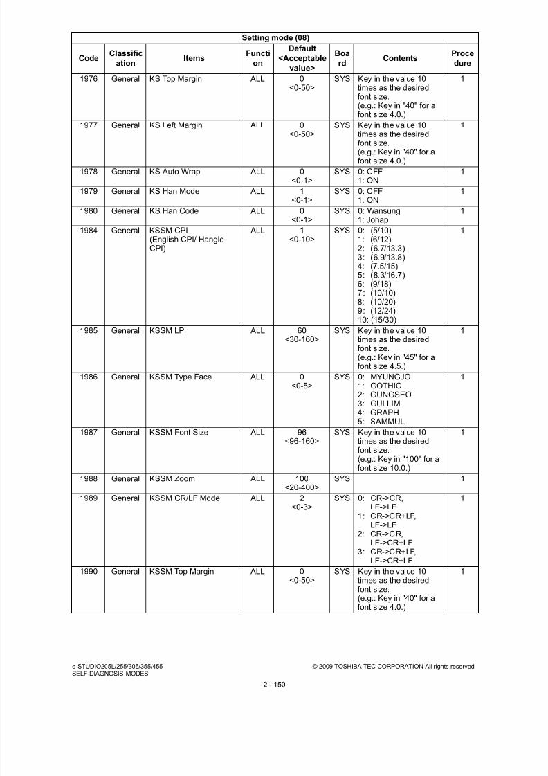
8/9/2019 Service manual E-studio 455
http://slidepdf.com/reader/full/service-manual-e-studio-455 178/670
e-STUDIO205L/255/305/355/455 © 2009 TOSHIBA TEC CORPORATION All rights reservedSELF-DIAGNOSIS MODES
2 - 150
1976 General KS Top Margin ALL 0<0-50>
SYS Key in the value 10times as the desiredfont size.(e.g.: Key in "40" for afont size 4.0.)
1
1977 General KS Left Margin ALL 0
<0-50>
SYS Key in the value 10
times as the desiredfont size.(e.g.: Key in "40" for afont size 4.0.)
1
1978 General KS Auto Wrap ALL 0<0-1>
SYS 0: OFF1: ON
1
1979 General KS Han Mode ALL 1<0-1>
SYS 0: OFF1: ON
1
1980 General KS Han Code ALL 0<0-1>
SYS 0: Wansung1: Johap
1
1984 General KSSM CPI(English CPI/ HangleCPI)
ALL 1<0-10>
SYS 0: (5/10)1: (6/12)2: (6.7/13.3)3: (6.9/13.8)
4: (7.5/15)5: (8.3/16.7)6: (9/18)7: (10/10)8: (10/20)9: (12/24)10: (15/30)
1
1985 General KSSM LPI ALL 60<30-160>
SYS Key in the value 10times as the desiredfont size.(e.g.: Key in "45" for afont size 4.5.)
1
1986 General KSSM Type Face ALL 0<0-5>
SYS 0: MYUNGJO1: GOTHIC
2: GUNGSEO3: GULLIM4: GRAPH5: SAMMUL
1
1987 General KSSM Font Size ALL 96<96-160>
SYS Key in the value 10times as the desiredfont size.(e.g.: Key in "100" for afont size 10.0.)
1
1988 General KSSM Zoom ALL 100<20-400>
SYS 1
1989 General KSSM CR/LF Mode ALL 2<0-3>
SYS 0: CR->CR,LF->LF
1: CR->CR+LF,LF->LF
2: CR->CR,LF->CR+LF
3: CR->CR+LF,LF->CR+LF
1
1990 General KSSM Top Margin ALL 0<0-50>
SYS Key in the value 10times as the desiredfont size.(e.g.: Key in "40" for afont size 4.0.)
1
Setting mode (08)
CodeClassific
ationItems
Functi
on
Default
<Acceptable
value>
Boa
rdContents
Proce
dure
8/9/2019 Service manual E-studio 455
http://slidepdf.com/reader/full/service-manual-e-studio-455 179/670
© 2009 TOSHIBA TEC CORPORATION All rights reserved e-STUDIO205L/255/305/355/455SELF-DIAGNOSIS MODES
2 - 151
1991 General KSSM Left Margin ALL 0<0-50>
SYS Key in the value 10times as the desiredfont size.(e.g.: Key in "40" for afont size 4.0.)
1
1992 General KSSM Auto Wrap ALL 0
<0-1>
SYS 0: OFF
1: ON
1
1993 General KSSM Han Mode ALL 1<0-1>
SYS 0: OFF1: ON
1
1994 General KSSM Han Code ALL 0<0-1>
SYS 0: Wansung1: Johap
1
2847 Imageprocessi
ng
Life correction switchingof drum reverse rotationamount
ALL e-STUDIO205L
/255/305:6e-
STUDIO355/455:
2<0~30>
M Set value x 4 msec. =Drum rotation time
e-STUDIO205L/255/305:
0: No correction1 to 30: Corrected(4 to 120 msec.:approx. 0.5 to 16
mm)e-STUDIO355/455:
0: No correction1 to 30: Corrected(4 to 120 msec.:approx. 0.8 to 25mm)
1
2848 Imageprocessi
ng
Life correction switchingof normal rotationamount after drumreverse rotation
ALL e-STUDIO205L
/255/305:14e-
STUDIO355/455:
9<0~30>
M 1
2987 Imageprocessi
ng
Cleaning bias outputcorrection betweensheets of paper
ALL 128<0~255>
M The transfer cleaningbias is output betweensheets of paper duringprinting so as to preventthe toner on thephotoconductive drumfrom adhering to thetransfer roller. Thiscode is used to correctthe output betweensheets of paper to thatadjusted in 05-2084(Transfer cleaning biasadjustment (negative)).The larger the settingvalue is, the higher thevalue of the current(more negative) is. Thiscauses a reduction inthe toner adhering
between sheets ofpaper. Note that tonerwith a different polaritywill adhere easily if thesetting value is toolarge. (Recommendedrange: 125 to 138)
1
3015 Scanner Pre-scan settingswitchover
ALL 0<0-1>
SYS 0: Not performing pre-scanning
1: Performing pre-scanning
1
3508 General Maximum number ofrecords in address book
ALL 0<0~1>
SYS 0: 1000 records1: 3000 records
1
Setting mode (08)
CodeClassific
ationItems
Functi
on
Default
<Acceptable
value>
Boa
rdContents
Proce
dure

8/9/2019 Service manual E-studio 455
http://slidepdf.com/reader/full/service-manual-e-studio-455 180/670
e-STUDIO205L/255/305/355/455 © 2009 TOSHIBA TEC CORPORATION All rights reservedSELF-DIAGNOSIS MODES
2 - 152
3612 General Date of unpacking ALL -<13 digits>
SYS Year/month/date/day/hour/minute/secondExample:03 07 0 13 13 27 48“Day” - “0” is for“Sunday”. Proceeds
Monday throughSaturday from “1” to “6”.
11
3615 General List print USB storagesetting
ALL 0<0-1>
SYS 0: Enable(USB storageavailable)
1: Disable(USB storage notavailable)
1
3619 General Clearing of servicehistory list file
ALL - SYS Initializes the servicehistory list file.
3
3630 Maintenance
Default settingautomation after remoteupdate
ALL 0<0-6>
SYS 0: Normal startup1: Remote update in
process2: Remote update
failed3: Remote updatecompleted
4: Self-diagnosticmode initializationcompleted(initializationperformed)
5: Self-diagnosticmode initializationcompleted(initialization notperformed)
6: Self-diagnosticmode initialization
completed(initialization failed)
2
3635 Userinterface
Trial copy function ALL 1<0~1>
SYS 0: Disabled1: Enabled
1
3722 Network PDC/BDC timeout valueof Windows Domain
Authentication (Unit:Seconds)
ALL 60<1-180>
NIC Applied to the deviceauthentication
12
3723 Network User authenticationPDC/BDC time-outperiod (Unit: Seconds)
ALL 30<1-180>
NIC Applied to the userauthentication
12
3724 Network Windows Domain Authentication method ofWindows Domain/User
Authentication
ALL 1<1-3>
NIC 1: Auto2: Kerberos3: NTLMv2
12
3725 Network IPP max connection ALL 16<1-16>
NIC 12
3726 Network IPP active connection ALL 10<1-16>
NIC 12
3727 Network LPD max connection ALL 10<1-16>
NIC 12
3728 Network LPD active connection ALL 10<1-16>
NIC 12
3729 Network ATalk PS maxConnection
ALL 10<1-16>
NIC 12
3730 Network ATalk PS activeConnection
ALL 10<1-16>
NIC 12
Setting mode (08)
CodeClassific
ationItems
Functi
on
Default
<Acceptable
value>
Boa
rdContents
Proce
dure

8/9/2019 Service manual E-studio 455
http://slidepdf.com/reader/full/service-manual-e-studio-455 181/670
© 2009 TOSHIBA TEC CORPORATION All rights reserved e-STUDIO205L/255/305/355/455SELF-DIAGNOSIS MODES
2 - 153
3731 Network Raw TCP maxConnection
ALL 10<1-16>
NIC 12
3732 Network Raw TCP activeconnection
ALL 10<1-16>
NIC 12
3736 Network DNS Client Time Out ALL 60<1-180>
NIC Use when a timeoutoccurred at DNS clientconnection
12
3737 Network DDNS Client Time Out ALL 60<1-180>
NIC Use when a timeoutoccurred at DDNSclient connection
12
3738 Network HTTP Client Time Out(EWB and Satellite)
ALL 60<1-180>
NIC Use when a timeoutoccurred at HTTP clientconnection
12
3739 Network FTP Client Time Out(SCAN)
ALL 30<1-180>
NIC Use when a timeoutoccurred at FTP clientconnection
12
3740 Network SNTP Client Time Out ALL 30<1-180>
NIC Use when a timeoutoccurred at SNTP clientconnection
12
3741 Network SMTP Client Time Out ALL 30<1-180> NIC Use when a timeoutoccurred at SMTP clientconnection
12
3742 Network POP3 Client Time Out ALL 30<1-180>
NIC Use when a timeoutoccurred at POP3 clientconnection
12
3743 Network LDAP Client Time Out ALL 30<1-180>
NIC Use when a timeoutoccurred at LDAP clientconnection
12
3744 Network POP3 Authenticationmethod
ALL 1<1-3>
NIC POP3 authenticationmethod setting1: Disable (Default)2: NTLM3: Kerberos
12
3745 General Secure DDNS PrimaryLogin Name
ALL - NIC Login name for loginwith the Primary DDNSUp to 128 letters
12
3746 General Secure DDNS PrimaryLogin Password
ALL -<1-128>
NIC Login password forlogin with the PrimaryDDNSUp to 128 letters
12
3747 General Secure DDNSSecondary Login Name
ALL - NIC Login name for loginwith the SecondaryDDNSUp to 128 letters
12
3748 General Secure DDNSSecondary LoginPassword
ALL - NIC Login password forlogin with theSecondary DDNSUp to 128 letters
12
3749 General DPWS Friendly Name ALL - NIC MFP name indicated inDPWS search result<Default value>TOSHIBAe-STUDIOxxx[NIC serial number]Up to 127 letters
12
Setting mode (08)
CodeClassific
ationItems
Functi
on
Default
<Acceptable
value>
Boa
rdContents
Proce
dure

8/9/2019 Service manual E-studio 455
http://slidepdf.com/reader/full/service-manual-e-studio-455 182/670
e-STUDIO205L/255/305/355/455 © 2009 TOSHIBA TEC CORPORATION All rights reservedSELF-DIAGNOSIS MODES
2 - 154
3750 General DPWS Printer Name ALL - NIC Printer name used forinstalling the printerwith DPWS<Default value>TOSHIBAe-STUDIOxxx Printer-
[NIC serial number]Up to 127 letters
12
3751 General DPWS Scanner Name ALL - NIC Scanner name used forinstalling the printerwith DPWS<Default value>TOSHIBAe-STUDIOxxx Scanner-[NIC serial number]Up to 127 letters
12
3752 General DPWS PrinterInformation
ALL - NIC Information regardingDPWS printer <Default value> NULLUp to 127 letters
12
3753 General DPWS ScannerInformation ALL - NIC Information regardingDPWS scanner <Default value> NULLUp to 127 letters
12
3754 Network Switching DPWS Printersetting
ALL 1<1-2>
NIC DPWS printer /DPWSsecure printer functionis switched.1: Enabled2: Disabled3: Security enabled
12
3755 Network Switching DPWSScanner setting
ALL 1<1-2>
NIC DPWS scanner functionis switched.1: Enabled2: Disabled
12
3757 Network DPWS Discovery PortNumber
ALL 3702<1-65535>
NIC Port number used forDPWS Discovery
12
3758 Network DPWS MetadataExchange Port Number
ALL 50081<1-65535>
NIC Port number used forDPWS MetadataExchange
12
3759 Network DPWS Print PortNumber
ALL 50082<1-65535>
NIC Port number used forDPWS Print
12
3760 Network DPWS Scan PortNumber
ALL 50083<1-65535>
NIC Port number used forDPWS Scan
12
3765 Network DPWS Print Maxnumbers of connection
ALL 10<1-20>
NIC Maximum numbersreceived from morethan one connectionrequest in the DPWSprint
12
3766 Network DPWS Print Maxnumbers of reception ALL 10<1-20> NIC Maximum numbers ofdata received frommore than one clients inthe DPWS print
12
3767 Network Switching IPv6 setting ALL 2<1-2>
NIC IPv6 function isswitched.1: Enabled2: Disabled
12
3768 Network Switching IP(IPv6) Address Acquisition
ALL 2<1-2>
NIC IP(IPv6) Address Acquisition setting isswitched.1: Manual2: Auto configuration
12
Setting mode (08)
CodeClassific
ationItems
Functi
on
Default
<Acceptable
value>
Boa
rdContents
Proce
dure

8/9/2019 Service manual E-studio 455
http://slidepdf.com/reader/full/service-manual-e-studio-455 183/670

8/9/2019 Service manual E-studio 455
http://slidepdf.com/reader/full/service-manual-e-studio-455 184/670
e-STUDIO205L/255/305/355/455 © 2009 TOSHIBA TEC CORPORATION All rights reservedSELF-DIAGNOSIS MODES
2 - 156
3785 Network DPWS IPv4 or IPv4 withIPv6
ALL 2<1-2>
NIC Either IPv4 only or IPv6together with it isselected to operatePrint, Scan andSecurity related withDPWS.
1: Multi (IPv4 andIPv6)
2: IPv4
12
3793 Network Switching LLTD setting ALL 1<1-2>
NIC LLTD function isswitched.1: Enabled2: Disabled
12
3796 Network DPWS event rate ALL 5<1-600>
NIC Sets the value ofDPWS event rate from1 to 600 seconds
12
3797 General Response to PJL jobcommands
ALL 1<0-1>
SYS During bidirectionalcommunication, thenext job will not beaccepted until the
printing of the sent data(all pages) is finished. Ifthe next job must beaccepted duringbidirectionalcommunication, set thevalue at “0: (Solicited)”.0: (Solicited) -
Immediatelyresponds to the hostside after thecompletion of RIP.
1: (Unsolicited) -Responds to thehost side after the
printing is finished.
1
3802 General USB media directprintingPaper size
ALL EUR: 6UC: 2JPN: 6<0-13>
SYS 0: Ledger 1: Legal2: Letter 3: Computer 4: Statement5: A36: A47: A58: A69: B410: B511: Folio12: Legal13"13: Letter Square
1
3803 General USB media directprinting function setting
ALL 1<0-1>
SYS Sets the USB mediadirect printing function.0: Disabled1: Enabled
1
3804 Scanner List Analysis Logic ofScan to File (FTP)
ALL 0<0-1>
SYS Acquisition of Contentsin Host side is switchedby Scan to File (FTP).0: Logic11: Logic2
1
Setting mode (08)
CodeClassific
ationItems
Functi
on
Default
<Acceptable
value>
Boa
rdContents
Proce
dure

8/9/2019 Service manual E-studio 455
http://slidepdf.com/reader/full/service-manual-e-studio-455 185/670
© 2009 TOSHIBA TEC CORPORATION All rights reserved e-STUDIO205L/255/305/355/455SELF-DIAGNOSIS MODES
2 - 157
3805 Scanner DepartmentManagement setting byRemote Scan
ALL 3<0-3>
SYS DepartmentManagement is setwhen Remote Scan isperformed.0: w/o GUI OFF,
w/ GUI OFF
1: w/o GUI ON,w/ GUI OFF
2: w/o GUI OFF, w/ GUI ON
3: w/o GUI ON,w/ GUI ON
1
3810 Network Direct SMTPcommunication setting
ALL 0<0-1>
SYS When an Internet Fax issent, Direct SMTPcommunication is set.0: Disabled1: Enabled
When "0: Disabled" isset, an Internet Fax issent using an SMTPserver.
When "1: Enabled" isset, direct SMTPcommunication isenabled and an InternetFax is sent to MFPs onthe intranet withoutusing an SMTP server.Since no SMTP serveris used, the SSLencryption and SMTP-
AUTH function cannotbe used for internet Faxtransmission.If "1: Enabled" is set in08-3810, set "1:Enabled" in 08-3812 aswell.
1
3811 Network Image encrypting at theDirect SMTPcommunication
ALL 0<0-1>
SYS When Direct SMTPcommunication isperformed, an attachedimage is encrypted.0: Disabled1: Enabled
1
3812 Scanner Dummy full mode at theInternet Faxtransmission
ALL 0<0-1>
SYS When an Internet Fax issent, the resolution ratioand the paper size of anattached image are set
to the full mode.0: Disabled1: EnabledIf "1: Enabled" is set in08-3810, set "1:Enabled" in 08-3812 aswell.
1
3815 Scanner XPS file thumbnailaddition
ALL 1<0-1>
SYS Thumbnail is added tothe XPS file producedby the Scan function.0: Not added1: Only the top page
added
1
Setting mode (08)
CodeClassific
ationItems
Functi
on
Default
<Acceptable
value>
Boa
rdContents
Proce
dure

8/9/2019 Service manual E-studio 455
http://slidepdf.com/reader/full/service-manual-e-studio-455 186/670

8/9/2019 Service manual E-studio 455
http://slidepdf.com/reader/full/service-manual-e-studio-455 187/670
© 2009 TOSHIBA TEC CORPORATION All rights reserved e-STUDIO205L/255/305/355/455SELF-DIAGNOSIS MODES
2 - 159
3848 General Restriction on AddressBook destination setting
FAX 0<0-1>
SYS Availability ofdestination selectionfrom the Address Bookis switched as one ofFAX mistransmissionprevention functions
when setting FAXdestinations.0: OFF (Disabled)1: ON (Enabled)
1
3849 General Restriction ondestination direct entry
FAX 0<0-1>
SYS Availability of directentry is switched as oneof FAX mistransmissionprevention functionswhen setting FAXdestinations.0: OFF (Disabled )1: ON (Enabled)
1
3850 General Remote ScanUser authentication
ALL 0<0-3>
SYS User authentication onRemote Scan driver is
switched according tothe availability of GUI.0: OFF (No GUI) / OFF
(GUI installed)1: ON (No GUI) / OFF
(GUI installed)2: OFF (No GUI) / ON
(GUI installed)3: ON (No GUI) / ON
(GUI installed)
1
3851 General Template display ALL 0<0-1>
SYS The order of displayingtemplates on the LCDscreen is switched.0: Order of IDs1: Alphabetical order
1
3852 User interface
Automatic summer timechange
ALL 0<0-1>
SYS Automatic summer timechange on the daypreviously set isswitched.0: Disabled1: Enabled
1
3853 User interface
Summer time modeOffset value
ALL 2<0-7>
SYS Summer time is startedas follows when 08-3852 is enabled.0: +2:00 1: +1:302: +1:00 3: +0:304: 0:30 5: -1:006: -1:30 7: -2:00
1
3854 User
interface
Summer time mode
Starting month
ALL 1
<1-12>
SYS The month in which
summer time is startedis set.1: January2: February3: March4: April5: May6: June7: July8: August9: September 10: October 11: November 12: December
1
Setting mode (08)
CodeClassific
ationItems
Functi
on
Default
<Acceptable
value>
Boa
rdContents
Proce
dure

8/9/2019 Service manual E-studio 455
http://slidepdf.com/reader/full/service-manual-e-studio-455 188/670
e-STUDIO205L/255/305/355/455 © 2009 TOSHIBA TEC CORPORATION All rights reservedSELF-DIAGNOSIS MODES
2 - 160
3855 User interface
Summer time modeStarting week
ALL 1<1-5>
SYS The week in whichsummer time is startedis set.1: 1st2: 2nd3: 3rd
4: 4th5: Last
1
3856 User interface
Summer time modeStarting day
ALL 0<0-6>
SYS The day on whichsummer time is startedis set.0: Sunday1: Monday2: Tuesday3: Wednesday4: Thursday5: Friday6: Saturday
1
3857 User interface
Summer time modeStarting time
ALL 0<00-23>
SYS The time at whichsummer time is started
is set.00-23
1
3858 User interface
Summer time modeStarting minute
ALL 0<00-59>
SYS The minute at whichsummer time is startedis set.00-59
1
3859 User interface
Summer time modeEnding month
ALL 1<1-12>
SYS The month in whichsummer time is endedis set.1: January2: February3: March4: April5: May6: June
7: July8: August9: September 10: October 11: November 12: December
1
3860 User interface
Summer time modeEnding week
ALL 1<1-5>
SYS The week in whichsummer time is endedis set.1: 1st2: 2nd3: 3rd4: 4th5: Last
1
3861 User interface Summer time modeEnding day ALL 0<0-6> SYS The day on whichsummer time is endedis set.0: Sunday1: Monday2: Tuesday3: Wednesday4: Thursday5: Friday6: Saturday
1
3862 User interface
Summer time modeEnding time
ALL 0<00-23>
SYS The time at whichsummer time is endedis set.00-23
1
Setting mode (08)
CodeClassific
ationItems
Functi
on
Default
<Acceptable
value>
Boa
rdContents
Proce
dure

8/9/2019 Service manual E-studio 455
http://slidepdf.com/reader/full/service-manual-e-studio-455 189/670
© 2009 TOSHIBA TEC CORPORATION All rights reserved e-STUDIO205L/255/305/355/455SELF-DIAGNOSIS MODES
2 - 161
3863 User interface
Summer time modeStarting minute
ALL 0<00-59>
SYS The minute at whichsummer time is endedis set.00-59
1
3864 Network Disclosure of telnetfunction
ALL 0<0-1>
SYS 0: Not disclosed1: Disclosed
When this value is setat “1”, the value of code08-9834 must be “0”.When this value is setat “0”, the value of code08-3865 must be “2”.
1
3865 Network Availability of TelnetServer
ALL 2<1-2>
NIC Availability of TelnetServer is switched.1: Enabled2: Disabled
12
3866 Network TCP port number oftelnet server
ALL 23<1-65535>
NIC A port number forTelnet Server is set.
12
3867 Network Telnet Server Server administrator's
user name
ALL Admin<Maximum
15 letters>
NIC A user name for theTelnet Server
administrator isconfirmed.
12
3868 Network Telnet Server Server administrator'spassword
ALL System<Maximum15 letters>
NIC A password for theTelnet Serveradministrator is set.
12
3869 General Number of times of EWBdisplay for its restart
ALL 20<0-256>
SYS EWB is restarted whenthe EWB is displayedfor the preset number oftimes. Perform thiscode when you changethe number of times ofdisplay for resetting theEWB.EWB (Embedded WebBrowser) - Displays aweb page on the controlpanel. For displayingEWB, the ExternalInterface Enabler (GS-1020, optional) isrequired.
1
3870 General Display of electronickeys registered inequipment
ALL - - Displays electronickeys registered in theequipment.
3
3871 Network Setting for RBAC guestuser privilege
ALL 0<0-1>
SYS 0: Does not provide anyuser with guest userprivilege
1: Provides all userswith guest user
privilege
1
4016-0 Paperfeeding
ACCfunctionwhen adrawer isspecified
Copying ALL 0<0-1>
SYS Sets whether the ACCfunction is enabled onlyfor automatic drawerselection or enabledwhen a particulardrawer is specified aswell.0: Enabled only for
automatic drawerselection
1: Enabled when adrawer is specified
4
4016-1 Printing /BOXprinting
ALL 0<0-1>
SYS 4
Setting mode (08)
CodeClassific
ationItems
Functi
on
Default
<Acceptable
value>
Boa
rdContents
Proce
dure

8/9/2019 Service manual E-studio 455
http://slidepdf.com/reader/full/service-manual-e-studio-455 190/670
e-STUDIO205L/255/305/355/455 © 2009 TOSHIBA TEC CORPORATION All rights reservedSELF-DIAGNOSIS MODES
2 - 162
4549 General Detection setting of newor old fuser unit
ALL 0<0-1>
M 0: Enabled1: Disabled
2
4555 General Information check of newor old EPU memory
ALL 65280<0 to 65535>
M 65280 (0xFF00): NewEPU255 (0x00FF): InstalledEPU
2
4556 General Detection setting of newor old EPU
ALL 1<0-1>
M 0: Disabled1: Enabled
2
4581 General SRAM Buckup ALL - M The data in the SRAMis backed up in theEEPROM.
3
4582 General SRAM copy ALL - M The data in theEEPROM is copied tothe SRAM.
3
4621 Paperfeeding
Bypass paper sizedetection setting
PPC/PRT
0<0-1>
M Detects whether thesize of paper fed bybypass feeding is thesame as the paper sizeset on the control panel.If the sizes are not the
same, the warningmessage is displayed(Paper jam does notoccur).When the bypass papersize detection isbroken, the equipmentcan be used without thesize detection bydisabling this setting.
After repair, enable thissetting.0: Enabled1: Disabled
1
4622 Paperfeeding
Bypass paper sizedetection counter
PPC/PRT
0<0-65535>
M This is a counter forbypass paper sizedetection setting. If theprinting is executed withthe paper size thatdiffers from the papersize set on the controlpanel, the counter iscounted up.
1
5000 Imageprocessi
ng
Setting number of sheetsfor job end cleaningcontrol/Mass printing ofsmall size paper
ALL 0<0-9>
M Setting value x 10 =setting number ofsheets0: No execution when
the setting numberof sheets is
reached. (Cleaningbias switchingfrequency is thesame as that of 08-5001-0.)
1 to 9: Executed whenthe setting numberof sheets is reached(10 sheets to 90sheets)
1
Setting mode (08)
CodeClassific
ationItems
Functi
on
Default
<Acceptable
value>
Boa
rdContents
Proce
dure

8/9/2019 Service manual E-studio 455
http://slidepdf.com/reader/full/service-manual-e-studio-455 191/670
© 2009 TOSHIBA TEC CORPORATION All rights reserved e-STUDIO205L/255/305/355/455SELF-DIAGNOSIS MODES
2 - 163
5001-0 Imageprocessi
ng
Print job end cleaningbias polarity switchingfrequency
ALL 0<0-9>
M In the cleaningoperation of the transferroller at the end ofprinting, the cleaningbias, in which thepolarity is switched from
positive to negative, isoutput so that the toneradhering to the transferroller is returned to thephotoconductive drum.This code is used to setthe cleaning biasswitching frequency.Perform adjustmentwhen there is any stainon the back side of theprinted paper (leadingedge) caused by thetransfer roller.Note that the drum
driving time willincrease if the settingvalue of the cleaningbias switchingfrequency is too large.The setting code differsdepending on theoperation status of theequipment when thereis any stain on the backside of the printedpaper. Select the codefrom 5001 to 5003according to theoperation status.
Set this code whenthere is any stain on theback side of the printedpaper (leading edge)caused by the transferroller in normal printing.0: Once1: Twice2: Three times3: Four times4: Five times5: Six times6: Seven times7: Eight times8: Nine times9: Ten times
4
Setting mode (08)
CodeClassific
ationItems
Functi
on
Default
<Acceptable
value>
Boa
rdContents
Proce
dure

8/9/2019 Service manual E-studio 455
http://slidepdf.com/reader/full/service-manual-e-studio-455 192/670
e-STUDIO205L/255/305/355/455 © 2009 TOSHIBA TEC CORPORATION All rights reservedSELF-DIAGNOSIS MODES
2 - 164
5001-1 Imageprocessi
ng
Print job end cleaningbias polarity switchingfrequency (Bypass non-standard)
ALL 3<0-9>
M Set this code whenthere is any stain on theback side of the printedpaper (leading edge)caused by the transferroller in printing non-
standard paper from thebypass tray.0: Once1: Twice2: Three times3: Four times4: Five times5: Six times6: Seven times7: Eight times8: Nine times9: Ten times
4
5001-2 Imageprocessi
ng
Print job end cleaningbias polarity switchingfrequency (Mass printingof small size paper)
ALL 3<0-9>
M Set this code whenthere is any stain on theback side of the printedpaper (leading edge)caused by the transferroller in printingmaximum size paperafter printing a largeamount of small sizepaper (1 to 9).0: Once1: Twice2: Three times3: Four times4: Five times5: Six times6: Seven times7: Eight times8: Nine times9: Ten times
4
5002 Imageprocessi
ng
Job end cleaning biaspolarity switchingfrequency (When notprinting)
ALL 3<0-9>
M Set this code whenthere is any stain on theback side of the printedpaper (leading edge)caused by the transferroller after the warming-up, forced toner supplyor auto-toneradjustment.0: Once1: Twice2: Three times
3: Four times4: Five times5: Six times6: Seven times7: Eight times8: Nine times9: Ten times
1
Setting mode (08)
CodeClassific
ationItems
Functi
on
Default
<Acceptable
value>
Boa
rdContents
Proce
dure

8/9/2019 Service manual E-studio 455
http://slidepdf.com/reader/full/service-manual-e-studio-455 193/670
© 2009 TOSHIBA TEC CORPORATION All rights reserved e-STUDIO205L/255/305/355/455SELF-DIAGNOSIS MODES
2 - 165
5003 Imageprocessi
ng
Job end cleaning biaspolarity switchingfrequency (At jamrecovery)
ALL 3<0-9>
M Sets when there is anystain on the back sideof the printed paper(leading edge) causedby the transfer rollerafter a paper jam is
cleared.0: Once1: Twice2: Three times3: Four times4: Five times5: Six times6: Seven times7: Eight times8: Nine times9: Ten times
1
5101 Imageprocessi
ng
Toner cartridgecorrection tableswitching
ALL 0<0-2>
M Corrects the imagedensity according to thedetection value of thesensor. Changing thiscode varies thecorrection amount ofthe image density. Setthis code when thedensity is too high orlow.0: Middle-level
correction1: Low-level correction2: High-level correctionIt is hardly corrected atthe normal temperatureand humidity.
1
5130 Image
processing
Developer bias Hi1
correction (hardcopysecurity printing)
PRT 128
<0-255>
M Corrects the value of
the developer biasadjustment (05-205).
4
5131 Imageprocessi
ng
Main charger biascorrection (hardcopysecurity printing)
PRT 128<0- 255>
M Corrects the value ofthe main charger biasadjustment (05-210).
4
5132 Imageprocessi
ng
Laser output correction(hardcopy securityprinting)
PRT 128<0-255>
M Corrects the value ofthe laser poweradjustment (05-286).
4
Setting mode (08)
CodeClassific
ationItems
Functi
on
Default
<Acceptable
value>
Boa
rdContents
Proce
dure

8/9/2019 Service manual E-studio 455
http://slidepdf.com/reader/full/service-manual-e-studio-455 194/670

8/9/2019 Service manual E-studio 455
http://slidepdf.com/reader/full/service-manual-e-studio-455 195/670
© 2009 TOSHIBA TEC CORPORATION All rights reserved e-STUDIO205L/255/305/355/455SELF-DIAGNOSIS MODES
2 - 167
5333-0 Fuser Temperaturedrop duringprinting(Sub)
The firstdrop
ALL e-STUDIO205L
/255/305:-
e-STUDIO355/
455:0
<0 to 10>
M Setting value x -5°C:from 0°C to -50°CThis code is valid onlywhen "20" is set to 08-535-0.
4
5333-1 Theseconddrop
ALL e-STUDIO205L
/255/305:-
e-STUDIO355/
455:4
<0 to 10>
M 4
5333-2 The thirddrop
ALL e-STUDIO205L
/255/305:-e-
STUDIO355/455:
4<0 to 10>
M 4
5333-3 The forthdrop
ALL e-STUDIO205L
/255/305:-
e-STUDIO355/
455:4
<0 to 10>
M 4
Setting mode (08)
CodeClassific
ationItems
Functi
on
Default
<Acceptable
value>
Boa
rdContents
Proce
dure

8/9/2019 Service manual E-studio 455
http://slidepdf.com/reader/full/service-manual-e-studio-455 196/670
e-STUDIO205L/255/305/355/455 © 2009 TOSHIBA TEC CORPORATION All rights reservedSELF-DIAGNOSIS MODES
2 - 168
5334-0 Fuser Temperaturedropswitchingtime setting(Sub)
The firstdrop
ALL e-STUDIO205L
/255/305:-
e-STUDIO355/
455:10
<0 to 200>
M Setting value x 5seconds: from 0 to1000 secondsThis code is valid onlywhen "20" is set to 08-535-0.
4
5334-1 Theseconddrop
ALL e-STUDIO205L
/255/305:-
e-STUDIO355/
455:18
<0 to 200>
M 4
5334-2 The thirddrop
ALL e-STUDIO205L
/255/305:-e-
STUDIO355/455:24
<0 to 200>
M 4
5334-3 The forthdrop
ALL e-STUDIO205L
/255/305:-
e-STUDIO355/
455:75
<0 to 200>
M 4
Setting mode (08)
CodeClassific
ationItems
Functi
on
Default
<Acceptable
value>
Boa
rdContents
Proce
dure

8/9/2019 Service manual E-studio 455
http://slidepdf.com/reader/full/service-manual-e-studio-455 197/670
© 2009 TOSHIBA TEC CORPORATION All rights reserved e-STUDIO205L/255/305/355/455SELF-DIAGNOSIS MODES
2 - 169
5335-0 Fuser Temperaturedrop duringprinting onthick paper(Sub)
The firstdrop
ALL e-STUDIO205L
/255/305:-
e-STUDIO355/
455:0
<0 to 10>
M Setting value x -5°C:from 0°C to -50°CThis code is valid onlywhen "20" is set to 08-535-1.
4
5335-1 Theseconddrop
ALL e-STUDIO205L
/255/305:-
e-STUDIO355/
455:4
<0 to 10>
M 4
5335-2 The thirddrop
ALL e-STUDIO205L
/255/305:-e-
STUDIO355/455:
4<0 to 10>
M 4
5335-3 The forthdrop
ALL e-STUDIO205L
/255/305:-
e-STUDIO355/
455:4
<0 to 10>
M 4
Setting mode (08)
CodeClassific
ationItems
Functi
on
Default
<Acceptable
value>
Boa
rdContents
Proce
dure

8/9/2019 Service manual E-studio 455
http://slidepdf.com/reader/full/service-manual-e-studio-455 198/670
e-STUDIO205L/255/305/355/455 © 2009 TOSHIBA TEC CORPORATION All rights reservedSELF-DIAGNOSIS MODES
2 - 170
5336-0 Fuser Temperaturedropswitchingtime settingduringprinting on
thick paper(Sub)
The firstdrop
ALL e-STUDIO205L
/255/305:-
e-STUDIO355/
455:10
<0 to 200>
M Setting value x 5seconds: from 0 to1000 secondsThis code is valid onlywhen "20" is set to 08-535-1.
4
5336-1 Theseconddrop
ALL e-STUDIO205L
/255/305:-
e-STUDIO355/
455:18
<0 to 200>
M 4
5336-2 The thirddrop
ALL e-STUDIO205L
/255/305:-e-
STUDIO355/455:24
<0 to 200>
M 4
5336-3 The forthdrop
ALL e-STUDIO205L
/255/305:-
e-STUDIO355/
455:75
<0 to 200>
M 4
5554 Maintenance
PM counter setting valuefor developer material(K)
ALL Refer tocontent
<8 digits>
M Sets the number of printed sheets todisplay the messagethat prompts the PM of developer material.<Default>e-STUDIO205L:
JPD: 0Other: 80000
e-STUDIO255:JPD: 0Other: 100000
e-STUDIO305:JPD: 0
Other: 120000e-STUDIO355:
JPD: 0Other: 125000
e-STUDIO455:JPD: 0Other: 150000
1
Setting mode (08)
CodeClassific
ationItems
Functi
on
Default
<Acceptable
value>
Boa
rdContents
Proce
dure

8/9/2019 Service manual E-studio 455
http://slidepdf.com/reader/full/service-manual-e-studio-455 199/670
© 2009 TOSHIBA TEC CORPORATION All rights reserved e-STUDIO205L/255/305/355/455SELF-DIAGNOSIS MODES
2 - 171
5555 Maintenance
PM time counter settingvalue for developermaterial (K)
ALL e-STUDIO205L
/255/305:161000
e-STUDIO355/
455:135000
<8 digits>
M Sets the accumulateddriving time to displaythe message thatprompts the PM ofdeveloper material.
1
5562 Maintenance
PM counter setting valuefor part
ALL Refer tocontent
<8 digits>
M Sets the number ofprinted sheets todisplay the messagethat prompts the PM ofpart.<Default>e-STUDIO205L:
JPD: 0Other: 240000
e-STUDIO255:JPD: 0Other: 200000
e-STUDIO305:JPD: 0Other: 240000
e-STUDIO355:JPD: 0Other: 250000
e-STUDIO455:JPD: 0Other: 300000
1
5563 Maintenance
PM time counter settingvalue for part
ALL Refer tocontent
<8 digits>
M Sets the accumulateddriving time to displaythe message thatprompts the PM of part.<Default>
e-STUDIO205L:483000e-STUDIO255/305:
322000e-STUDIO355/455:
270000
1
5568 Maintenance
Current value of PMcounter for developermaterial (K)
ALL 0<8 digits>
M Displays the currentnumber of printedsheets.Counts up by turning onthe registration sensor.
1
5569 Maintenance
Current value of PM timecounter for developermaterial (K)
ALL 0<8 digits>
M Displays the currentdriving time.
1
5576 Maintenance
Current value of PMcounter for part
ALL 0<8 digits>
M Displays the currentnumber of printedsheets.Counts up by turning onthe registration sensor.
1
5577 Maintenance
Current value of PM timecounter for part
ALL 0<8 digits>
M Displays the currentdriving time of fuser.
1
5581 Maintenance
Switching of outputpages/driving counts atPM/developer material(K)
ALL 0<0-2>
M 0: Pages1: driving count2: Whichever comesfaster
1
Setting mode (08)
CodeClassific
ationItems
Functi
on
Default
<Acceptable
value>
Boa
rdContents
Proce
dure

8/9/2019 Service manual E-studio 455
http://slidepdf.com/reader/full/service-manual-e-studio-455 200/670
e-STUDIO205L/255/305/355/455 © 2009 TOSHIBA TEC CORPORATION All rights reservedSELF-DIAGNOSIS MODES
2 - 172
5585 Maintenance
Switching of outputpages/driving counts atPM/part
ALL 0<0-2>
M 0: Pages1: driving count2: Whichever comesfaster
1
6810-0 Counter Number ofoutput pages
in blackmode /Large size
1-UP /Duplex
printing
PPC 0<8 digits>
SYS Counts the number ofoutput pages.
4
6810-1 2-UP /Duplexprinting
PPC 0<8 digits>
SYS Counts the number ofoutput pages using[2IN1] or [MAGAZINESORT].
4
6810-2 2-UP /Simplexprinting
PPC 0<8 digits>
SYS Counts the number ofsheets using [2IN1] or[MAGAZINE SORT].
4
6810-3 4-UP /Duplexprinting
PPC 0<8 digits>
SYS Counts the number ofoutput pages using[4IN1].
4
6810-4 4-UP /Simplexprinting
PPC 0<8 digits>
SYS Counts the number ofsheets using [4IN1].
4
6810-7 1-UP /Simplexprinting
PPC 0<8 digits>
SYS Counts the number ofoutput pages.
4
6813-0 Counter Number ofoutput pagesof the printeror BOX /Large
1-UP /Duplexprinting
PRT 0<8 digits>
SYS Counts the number ofoutput pages.
4
6813-1 2-UP /Duplexprinting
PRT 0<8 digits>
SYS Counts the number ofoutput pages using[2IN1] or [MAGAZINESORT].* When printing is
performed using aWindows driver, the1-UP image will be
output.
4
6813-2 2-UP /Simplexprinting
PRT 0<8 digits>
SYS Counts the number ofsheets using [2IN1] or[MAGAZINE SORT].
4
6813-3 4-UP /Duplexprinting
PRT 0<8 digits>
SYS Counts the number ofoutput pages using[4IN1].
4
6813-4 4-UP /Simplexprinting
PRT 0<8 digits>
SYS Counts the number ofsheets using [4IN1].
4
6813-5 N-UP /Duplexprinting
PRT 0<8 digits>
SYS Counts the number ofoutput pages using [NIN1].
4
6813-6 N-UP /
Simplexprinting
PRT 0
<8 digits>
SYS Counts the number of
sheets using [N IN1].
4
6813-7 1-UP /Simplexprinting
PRT 0<8 digits>
SYS Counts the number ofoutput pages.
4
6815-0 Counter Number ofoutput pagesof the FAXprinting /Large
1-UP /Duplexprinting
FAX 0<8 digits>
SYS Counts the number ofoutput pages printedonly in the full colormode.
4
6815-7 1-UP /Simplexprinting
FAX 0<8 digits>
SYS Counts the number ofoutput pages printedonly in the full colormode.
4
Setting mode (08)
CodeClassific
ationItems
Functi
on
Default
<Acceptable
value>
Boa
rdContents
Proce
dure

8/9/2019 Service manual E-studio 455
http://slidepdf.com/reader/full/service-manual-e-studio-455 201/670
© 2009 TOSHIBA TEC CORPORATION All rights reserved e-STUDIO205L/255/305/355/455SELF-DIAGNOSIS MODES
2 - 173
6852-0 Counter Black job counter PPC 0<8 digits>
SYS Counter formonochrome copy
job.
4
6852-1 PRT 0<8 digits>
SYS Counter formonochrome print
job.
4
6852-2 PPC/PRT
0<8 digits>
SYS Total counter formonochrome copyand print job.
4
6977-0 Counter Tonercartridgeusagehistory (Lot.No.)
Latest ALL 0<8 digits>
M Displays the lotnumbers of the recent 5toner cartridges.
4
6977-1 1cartridgeearlier
ALL 0<8 digits>
M 4
6977-2 2cartridges earlier
ALL 0<8 digits>
M 4
6977-3 3cartridges earlier
ALL 0<8 digits>
M 4
6977-4 4cartridges earlier
ALL 0<8 digits>
M 4
7000 Image Clearing of adjustmentvalues of all imageprocess (PPC) related05 codes
PPC - SYS/M
Clears the gammacorrection table valuesand the adjustmentvalues of the following05 codes:05-501, 503, 504, 505,506, 507, 508, 509,510, 512, 514, 515,580, 590-0 to 2, 591-0to 2, 592-0 to 2, 604,605, 606, 648, 649,
667-0 to 4, 922, 925,931, 934, 937, 940,949-0 to 2, 1675, 7025,7033, 7034, 7041,7042, 7043, 7048,7236, 7237, 7279,7280, 7283, 7284,7285, 7286, 7287,7288, 7618
After executing thiscode, execute 08-4581.
3
7001 Image Clearing of all gammacorrection table values(PPC related areas only)
PPC - SYS Clears all the gammacorrection table valuesin the PPC relatedareas of the HDD.
3
7010 Image Destination switching forimage processingparameter
PPC 0<0-1>
SYS 0: Japan1: Overseas
1
7300 Image Clearing of adjustmentvalues of all imageprocess (network print)related 05 codes
PRT - SYS/M
Clears the adjustmentvalues of the following05 codes:05-654, 655, 656, 672-0 to 4, 7315-0 to 2,7316-0 to 2, 7317-0 to2, 7318-0 to 2, 7319-0to 2, 7320-0 to 2, 7351-0 to 4, 7352-0 to 4
After executing thiscode, execute 08-4581.
3
Setting mode (08)
CodeClassific
ationItems
Functi
on
Default
<Acceptable
value>
Boa
rdContents
Proce
dure

8/9/2019 Service manual E-studio 455
http://slidepdf.com/reader/full/service-manual-e-studio-455 202/670
e-STUDIO205L/255/305/355/455 © 2009 TOSHIBA TEC CORPORATION All rights reservedSELF-DIAGNOSIS MODES
2 - 174
7400 Image Clearing of adjustmentvalues of all imageprocess (network scan)related 05 codes
SCN - SYS Clears the adjustmentvalues of the following05 codes:05-840, 841, 842, 843,845, 846, 847, 848,860, 861, 862, 863,
880-0~2, 881-0 to 2,882-0 to 2, 883-0 to 2,1070, 1071, 1072,1075, 1076, 1077,1080, 1081, 1082,1086, 1087, 1088,7416, 7417, 7418,7421, 7422, 7423,7424, 7425, 7426,7468, 7470, 7475,7478, 7480-0~2, 8325,8326, 8327, 8330,8331, 8332, 8334,8340, 8341, 8342,8344, 8345, 8346,
8348, 8349, 8350,8361, 8362, 8363,8365, 8370, 8371,8372, 8373, 8375,8380, 8381, 8382,8385, 8386, 8387,8389, 8390, 8391,8392, 8394, 8395,8400, 8402, 8403,8404, 8405, 8407,8408, 8409
3
7500 Image Clearing of adjustmentvalues of all imageprocess (Fax) related 05codes
FAX - SYS/M
Clears the adjustmentvalues of the followingcodes:678-0 to 4, 700, 710,714, 725, 729
After executing thiscode, execute 08-4581.
3
8504 General Feeding method of oddpage number in duplexprinting(Raw print)
ALL 0<0-1>
SYS 0: One side1: Both sides
1
8506 General Forcible mode change incartridge empty status
ALL 1<0-2>
SYS 0: SLEEP MODE1: AUTO POWER
SAVE2: READY
1
8508 General Controlling method forprint image positionadjustment in secondary
scanning direction
PRT 2<0-2>
SYS 0: No control1: Cuts the image2: Shifts the image
1
8509 General Controlling amount forprint image positionadjustment in secondaryscanning direction
PRT 12<0-36>
SYS 0-36 1
8510 General Menu display forcontrolling print imageposition adjustment insecondary scanningdirection
PRT 0<0-1>
SYS 0: Menu not displayed1: Menu displayed
1
8511 General Wide A4 Mode (for PCL) PRT 0<0-1>
SYS 0: Disable1: Enable
1
Setting mode (08)
CodeClassific
ationItems
Functi
on
Default
<Acceptable
value>
Boa
rdContents
Proce
dure

8/9/2019 Service manual E-studio 455
http://slidepdf.com/reader/full/service-manual-e-studio-455 203/670
© 2009 TOSHIBA TEC CORPORATION All rights reserved e-STUDIO205L/255/305/355/455SELF-DIAGNOSIS MODES
2 - 175
8512 General Number of jobs in batchprocessing
ALL 10<2-10>
SYS 2-10:From 2 to jobs canbe specified
1
8515 General Outsideerase
judgementthreshold
(Default)
PPC PPC 0<-3-3>
SYS The larger the value is,area to be erasedincreases.The smaller the value
is, area to be eraseddecreases.
1
8516 SCN SCN 0<-3-3>
SYS 1
8517 General Remote Scan Userauthentication automaticlogin
ALL 1<0-1>
SYS 0: OFF(A user alwaysenters manually(current method))
1: ON(Previousauthenticationinformation will beused)
1
8518 General Overwriting mode forscanned files
ALL 0<0-3>
SYS 0: Always OFF1: Meta Scan function
ON / Normal scan
function OFF2: Meta Scan functionOFF / Normal scanfunction ON
3: Always ON
1
8519 General Scan PDF filePaper size
ALL 1<0-1>
SYS 0: Equivalent to scanimage size
1: Fitted into anystandard size
1
8523 Imageprocessi
ng
Toner near-empty statusMessage display
ALL 0<0-1>
SYS 0: ON1: OFF
1
8524 General No paper Message display
ALL 0<0-1>
SYS 0: ON1: OFF
1
8525 General No paper in the left trayof tandem LCF message ALL 0<0-1> SYS 0: ON1: OFF 1
8532 General Control panelBrightness leveladjustment
ALL 4<1-7>
SYS 1-7:Brightness level 1
8535 Network Storing network logs inthe HDD
ALL 2<1-2>
SYS Stores the network logsof SRAM in the HDDwhen network-relatedtrouble occurred.1: Enabled2: Disabled
1
8536 Network Data size when storingnetwork logs in the HDD
ALL 30<1-30>
SYS Specifies the size ofnetwork logs to bestored in the HDD.1-30:1-30 MB
1
8537 General Sorting method fordisplaying private print
jobs
PRT 0<0-1>
SYS Changes the sortingorder for print jobs onthe private print list.0: Descending order1: Ascending order
1
8538 Maintenance
(Remote)
Notification setting fortoner nearly empty
ALL 0<0-1>
SYS 0: Disabled1: Enabled
1
8540 Scanner Date/time format in theMeta Scan XML file
SCN 1<0-1>
SYS 0: YYYY/MM/DDhh:mm:ss.mmm
1: YYYY-MM-DDThh:mm:ss.mmmTZD
1
Setting mode (08)
CodeClassific
ationItems
Functi
on
Default
<Acceptable
value>
Boa
rdContents
Proce
dure

8/9/2019 Service manual E-studio 455
http://slidepdf.com/reader/full/service-manual-e-studio-455 204/670
e-STUDIO205L/255/305/355/455 © 2009 TOSHIBA TEC CORPORATION All rights reservedSELF-DIAGNOSIS MODES
2 - 176
8543 General Transition to the energysaving mode when in theSleep mode
ALL 1<0-1>
SYS 0: Disabled1: Enabled (depending
on conditions)
1
8544 General Interval setting fortransition to the SuperSleep mode
ALL 5<5-600>
SYS The interval betweenrecovering form theSuper Sleep mode
and making thetransition to theSuper Sleep modeagain. Unit:seconds.
1
8550 User interface
Keyboard layout forLanguage 8
ALL 0<0-2>
SYS 1: QWERTY layout(for Europe)
2: QWERTZ layout3: AZERTY layout
1
8551 User interface
Keyboard layout forLanguage 9
ALL 0<0-2>
SYS 1
8552 User interface
Keyboard layout forLanguage 10
ALL 0<0-2>
SYS 1
8553 User interface
Keyboard layout forLanguage 11
ALL 0<0-2>
SYS 1
8554 User interface
Keyboard layout forLanguage 12
ALL 0<0-2>
SYS 1
8555 User interface
Keyboard layout forLanguage 13
ALL 0<0-2>
SYS 1
8556 User interface
Keyboard layout forLanguage 14
ALL 0<0-2>
SYS 1
8560 Version Version of UI datalanguage 8 in HDD
ALL - - VXXX.XXX X 2
8561 Version Version of UI datalanguage 9 in HDD
ALL - - VXXX.XXX X 2
8562 Version Version of UI datalanguage 10 in HDD
ALL - - VXXX.XXX X 2
8563 Version Version of UI datalanguage 11 in HDD
ALL - - VXXX.XXX X 2
8564 Version Version of UI datalanguage 12 in HDD
ALL - - VXXX.XXX X 2
8565 Version Version of UI datalanguage 13 in HDD
ALL - - VXXX.XXX X 2
8566 Version Version of UI datalanguage 14 in HDD
ALL - - VXXX.XXX X 2
8570 Version Web UI data in HDDVersion: Language 8
ALL - - VXXX.XXX X 2
8571 Version Web UI data in HDDVersion: Language 9
ALL - - VXXX.XXX X 2
8572 Version Web UI data in HDDVersion: Language 10
ALL - - VXXX.XXX X 2
8573 Version Web UI data in HDDVersion: Language 11
ALL - - VXXX.XXX X 2
8575 Version Web UI data in HDDVersion: Language 13
ALL - - VXXX.XXX X 2
8676 Version Web UI data in HDDVersion: Language 14
ALL - - VXXX.XXX X 2
8800 Network Enabling / Disabling of802.1X
ALL 2<1-2>
NIC 1: Enabled2: Disabled
12
8801 Network 802.1X fallbackNumberof retry
ALL 3<3-10>
NIC 3-10:3-10 times 12
8802 Network Enabling / Disabling ofIPsec
ALL 2<1-2>
NIC 1: Enabled2: Disabled
12
8803 Network Enabling / Disabling ofSNMPv3
ALL 2<1-2>
NIC 1: Enabled2: Disabled
12
Setting mode (08)
CodeClassific
ationItems
Functi
on
Default
<Acceptable
value>
Boa
rdContents
Proce
dure

8/9/2019 Service manual E-studio 455
http://slidepdf.com/reader/full/service-manual-e-studio-455 205/670
© 2009 TOSHIBA TEC CORPORATION All rights reserved e-STUDIO205L/255/305/355/455SELF-DIAGNOSIS MODES
2 - 177
8804 Network Enabling / Disabling ofIP filtering
ALL 2<1-2>
NIC 1: Enabled2: Disabled
12
8805 Network Enabling / Disabling ofMAC address filtering
ALL 2<1-2>
NIC 1: Enabled2: Disabled
12
8806 Network SCEP CA Server Address1
ALL - NIC Maximum 128 letters 12
8807 Network SCEP CA Server Address2
ALL - NIC Maximum 128 letters 12
8808 Network SCEP CA Server Address3
ALL - NIC Maximum 128 letters 12
8809 Network SCEP Timeout1 ALL 30<1-300>
NIC Timeout period(second)
12
8810 Network SCEP Timeout2 ALL 30<1-300>
NIC Timeout period(second)
12
8811 Network SCEP Timeout3 ALL 30<1-300>
NIC Timeout period(second)
12
8812 Network SCEP Common Name Address1
ALL 1<1-2>
NIC 1: IP Address2: FQDN
12
8813 Network SCEP Common Name
Address2
ALL 1
<1-2>
NIC 1: IP Address
2: FQDN
12
8814 Network SCEP Common Name Address3
ALL 1<1-2>
NIC 1: IP Address2: FQDN
12
8815 Network Installation method ofIPsec certificate
ALL 2<2-3>
NIC 2: Import(Default)3: SCEP
12
8816 Network Installation method ofIEEE 802.1X certificate
ALL 2<2-3>
NIC 2: Import(Default)3: SCEP
12
8817 Network Enabling / Disabling ofWS Pull Scan when userauthentication is enabled
ALL 2<1-2>
NIC 1: Enable2: Disable (Default)
12
8818 Network Enabling / Disabling ofWS Pull Scan whendepartmentmanagement is enabled
ALL 2<1-2>
NIC 1: Enable2: Disable (Default)
12
8819 Network Enabling / Disabling of802.1X fallback
ALL 2<1-2>
NIC 1: Enable2: Disabled
12
8820 Network IPsec NAT-Traversalsetting
ALL 1<1-3>
NIC 1: Default(IKEv1: Disabled,IKEv2: Enabled)
2: Enable IKEv1 &IKEv2
3: Disable IKEv1 &IKEv2
12
8821 Network IPsec CRL setting ALL 2<1-2>
NIC 1: Enable CRL2: Disable CRL
12
Setting mode (08)
CodeClassific
ationItems
Functi
on
Default
<Acceptable
value>
Boa
rdContents
Proce
dure

8/9/2019 Service manual E-studio 455
http://slidepdf.com/reader/full/service-manual-e-studio-455 206/670
e-STUDIO205L/255/305/355/455 © 2009 TOSHIBA TEC CORPORATION All rights reservedSELF-DIAGNOSIS MODES
2 - 178
9022 General Easy setup productionprocess flag
ALL 99<0-99>
SYS Perform this code whenan error occurs duringthe easy setup(unpacking manualadjustment) and youwant to finish the easy
setup, or when the erroris canceled and youwant to restart theunpacking manualadjustment.0: Unpacking mode
finished (beforeunpacking isstarted)
1: Auto-toneradjustment finished(The messageprompting theinstallation of thetoner cartridge is
displayed.)2: Toner cartridge is
installed99: All the unpacking
adjustmentsfinished
Only 0 to 2 and 99 areavailable for this code.
1
9051 Userinterface
Panel calibration settingvalue display
ALL 0<0-1>
SYS Switches whether thescreen for displayingpanel calibration settingvalues is displayed ornot.0: Disabled (screen
not displayed)1: Enabled (screen
displayed)
1
Setting mode (08)
CodeClassific
ationItems
Functi
on
Default
<Acceptable
value>
Boa
rdContents
Proce
dure

8/9/2019 Service manual E-studio 455
http://slidepdf.com/reader/full/service-manual-e-studio-455 207/670
© 2009 TOSHIBA TEC CORPORATION All rights reserved e-STUDIO205L/255/305/355/455SELF-DIAGNOSIS MODES
2 - 179
9090 General Printer all clear ALL - M If the data of the self-diagnosis 05/08 codebecome abnormal,performing 08-4582 canrestore them. If not,perform this code. All
data of the self-diagnosis 05/08 codewith “M" in the "SRAM"field are initialized,except the destinationsetting data.Perform this code if theabove problem occursor the data of the self-diagnosis 05/08 codeand the backup dataare damaged afterreplacing the LGCboard and performing08-4582.
Procedure:1. Set 08-201.2. Perform 08-9090.3. Perform 08-4581.4. Set 08-203 to "0".
If you have got theorder wrong, repeat theprocedure from step 1.
After this code isperformed, it isnecessary to replacethe developer materialand to adjust the auto-
toner sensor. Since theinformation of the PMcounter is initialized,enter it again asrequired.
3
9117 General Raw printing job(Blank page will not beprinted)
PRT 0<0-1>
SYS 0: OFF1: ON
1
Setting mode (08)
CodeClassific
ationItems
Functi
on
Default
<Acceptable
value>
Boa
rdContents
Proce
dure

8/9/2019 Service manual E-studio 455
http://slidepdf.com/reader/full/service-manual-e-studio-455 208/670
e-STUDIO205L/255/305/355/455 © 2009 TOSHIBA TEC CORPORATION All rights reservedSELF-DIAGNOSIS MODES
2 - 180
9185-0 Userinterface
Feedingpaper media
Copier ALL 1<1, 16, 17>
SYS Sets a media type for APS drawer searchingin the copier functions.
Each bit 0: Excludedfrom feeding target
mediaEach bit 1: Feeding
target media
bit 0: Plain paper bit 1: N/A (Always set
"0")bit 2: N/A (Always set
"0")bit 3: N/A (Always set
"0")bit 4: Thick paper 1
4
9185-1 Userinterface
Printer/Box
ALL 1<1, 16, 17>
SYS Sets a media type toprint on plain paper inthe printer/boxfunctions. This setting isused for drawersearching or media typeinconsistency
judgment. The settingresult does not affectother media types,other than plain paper.
Each bit 0: Excludedfrom feeding targetmedia
Each bit 1: Feedingtarget media
bit 0: Plain paper bit 1: N/A (Always set
"0")bit 2: N/A (Always set
"0")bit 3: N/A (Always set
"0")bit 4: N/A (Always set
"0")
4
9300 Paperfeeding
Drawer 1Paper information
ALL 0<0-1>
SYS 0: Plain paper1: Thick paper 1
1
9301 Paperfeeding
Drawer 2Paper information
ALL 0<0-1>
SYS 0: Plain paper1: Thick paper 1
1
9302 Paper
feeding
PFP 1
Paper information
ALL 0
<0-1>
SYS 0: Plain paper
1: Thick paper 1
1
9303 Paperfeeding
PFP 2Paper information
ALL 0<0-1>
SYS 0: Plain paper1: Thick paper 1
1
9304 Paperfeeding
LCFPaper information
ALL 0<0-1>
SYS 0: Plain paper8: Recycled paper Only “0” and “8” areacceptable.
1
9305 Paperfeeding
Bypass trayPaper information
ALL 0<0-3, 16, 32>
SYS 0: Plain paper1: Thick paper 12: Thick paper 23: Thick paper 316: OHP film32: Envelope
1
Setting mode (08)
CodeClassific
ationItems
Functi
on
Default
<Acceptable
value>
Boa
rdContents
Proce
dure

8/9/2019 Service manual E-studio 455
http://slidepdf.com/reader/full/service-manual-e-studio-455 209/670
© 2009 TOSHIBA TEC CORPORATION All rights reserved e-STUDIO205L/255/305/355/455SELF-DIAGNOSIS MODES
2 - 181
9359 Userinterface
Printing resume after jam releasing
ALL 0<0-1>
SYS 0: Auto resume1: Resume by users
1
9379 Userinterface
AES data encryptionfunction setting (Exceptfor CND)
ALL 0<0-2>
SYS 0: Encryption invalid1: Encryption valid
(Security priority)Encrypts all of the
user's data.2: Encryption valid
(Performancepriority)Encrypts the user'sdata except the filestemporarily createdand deleted in theimage processingsuch as copying orprinting.
1
9384 Network Default E-mail fi le format(Color/ACS mode)
ALL 1<0-8>
SYS 0: TIFF (Multi)1: PDF (Multi)2: JPG
3: TIFF (Single)4: PDF (Single)5: SLIM PDF (Multi)6: SLIM PDF (Single)7: XPS (Multi)8: XPS (Single)
1
9394 Network Single-page option forstoring File and sendingEmail
ALL 0<0-1>
SYS 0: Sets 1 page as 1 file1: Makes a file based
on the original
1
9629 Network Attribute name for LDAPRole Based Access
ALL eBMUserRole
<->
SYS Up to 32 letters 11
9739 Maintenance
Remote serviceToner-end notification
ALL 0<0-2>
SYS 0: RDMS toner emptynotified immediately
1: RDMS toner empty
notified once a day2: RDMS toner empty
not notified
1
9746 Network 802.1X/Dynamic WEPselecting button display
ALL 0<0-1>
SYS Switches whether aselecting button forSecurity mode 802.1X/Dynamic WEP isdisplayed or not.1: Not displayed2: Displayed
1
9747 Network PMK Cache setting ALL 1<1-2>
NIC Sets whether PMKCache is enabled ordisabled when WPA2 isselected. Set “1”
(Enable) when the PMKCache function need tobe ON.
1: Disable (Default)2: Enable
12
9749 Network WIA Scan Driver SCN 1<1-2>
NIC Selects WIA ScanDriver.1: TTEC2: Microsoft
12
Setting mode (08)
CodeClassific
ationItems
Functi
on
Default
<Acceptable
value>
Boa
rdContents
Proce
dure

8/9/2019 Service manual E-studio 455
http://slidepdf.com/reader/full/service-manual-e-studio-455 210/670
e-STUDIO205L/255/305/355/455 © 2009 TOSHIBA TEC CORPORATION All rights reservedSELF-DIAGNOSIS MODES
2 - 182
9798 Network Temporarycommunicationpassword setting
ALL - SYS Sets a temporarycommunicationpassword.The password can beentered inalphanumeric
characters (A to Z, a toz, 0 to 9) up to 10 digits.The entered passwordis displayed with “*” onthe touch panel and theself-diagnostic lists.(Maximum 10 digits,minimum 5 digits)
11
9799 General Local authenticationmode switchover
ALL 0<0-1>
SYS Sets the authenticationmode when “0: (Internalauthentication)” isselected in the code 08-1471.0: Card ID differs from
the User ID1: Card ID is the same
as the User ID
1
9804 Imageprocessi
ng
Forcible mode change intoner empty status
ALL 1<0-2>
SYS 0: SLEEP MODE1: AUTO POWER
SAVE2: READY
1
9805 Laser Polygonal motor standbyrotationShift waiting time at jobend
ALL 3<0-9>
SYS 0: 0 sec.(current setting)(Polygonal motorready rotation at jobend)
1 to 9:Setting value x 5sec.
1
9811-0 Finisher StaplingsettingMaximumnumber ofsheetsacceptableexceedingupper limit /Long size
Plain/Recycled
ALL 0<-50-50>
SYS -50 to 50 4
9811-1 Thick1 ALL 0<-50-50>
SYS 4
9811-2 Thick2 ALL 0<-50-50>
SYS 4
9811-3 Thick3 ALL 0<-50-50>
SYS 4
9814 General Number ofoutput pagesfor pausingcontinuousprinting for2nd transferresistancedetectioncontrol
At normaltemperatures
ALL 4<0-100>
SYS When the setting valueof this code is “1” orhigher, the 2nd transferresistance detection isperformed every timethe number of pages of(setting value X 100)have output.
1
9815 General At lowtemperatures
ALL 10<0-100>
SYS When the setting valueof this code is “1” orhigher, the 2nd transferresistance detection isperformed every timethe number of pages of(setting value X 10)have output.
1
Setting mode (08)
CodeClassific
ationItems
Functi
on
Default
<Acceptable
value>
Boa
rdContents
Proce
dure

8/9/2019 Service manual E-studio 455
http://slidepdf.com/reader/full/service-manual-e-studio-455 211/670
© 2009 TOSHIBA TEC CORPORATION All rights reserved e-STUDIO205L/255/305/355/455SELF-DIAGNOSIS MODES
2 - 183
9819 General STAGE SSL ALL 1<0-1>
SYS When remote scanningis performed, the SSLcommunication iscarried out.0: Disabled1: Enabled (SSL
communication)
1
9822 General STAGE SSL portnumber
ALL 20443<0-65535>
SYS When remote scanningis performed using SSLcommunication, theSSL port number is set.
1
9825 Image Image quality of theblack part in the ACSmode
ALL 0<0-1>
SYS 0: Black1: Gray scale
1
9826 General Disabling Media FileSave
ALL 0<0-1>
SYS 0: Invalid1: Valid
1
9828 General Remote scanning mode ALL 1<0-1>
SYS 0: Batch1: Sequential
1
9829 General Departmentmanagement limitation
setting
ALL 0<0-1>
SYS Decide the defaultlimitation setting when
the new departmentcode is created.0: No limit1: Limited
1
9847 Finisher Hole punching setting ALL 0<0-1>
SYS 0: Invalid1: Valid
1
9880 General Total countertransmission date setting(2)
ALL 0<0-31>
SYS 0 to 31 1
9881 General Day of total counter datatransmission
ALL 0<0-127>
SYS 1 byte 00000000(0)-01111111(127)From the 2nd bit -Sunday, Monday,Tuesday, Wednesday,
Thursday, Friday,Saturday
1
9882 Electronic filing
Display mode of theused capacity on the e-Filing administrator page
ALL 1<0-1>
SYS 0: All files searchmode
1: Performance prioritymode
1
9883 General Hardcopy securityprinting level 1
PPC 0<0-1>
SYS Sets whether thehardcopy securityprinting is enabled ordisabled.0: Disabled1: Enabled
2
9884 Counter Count switching ofhardcopy security
printing level 1
PPC 0<0-1>
SYS Sets the way ofcounting for hardcopy
security printing
2
9886 Scanning Decimal point indicationfor Enhanced ScanTemplate
SCN EUR: 0Other: 1<0-1>
SYS 0: Comma1: Period
1
9888 Scanner Permission setting forchanging the scanparameter whenrecalling an extension
SCN 0<0-1>
SYS 0: Prohibited1: Permitted
1
9889 General Acceptance of datacloning using USBmedia
ALL 1<0-1>
SYS Acceptance of theusage of the USB datacloning tool0: Accepted1: Not accepted
2
Setting mode (08)
CodeClassific
ationItems
Functi
on
Default
<Acceptable
value>
Boa
rdContents
Proce
dure

8/9/2019 Service manual E-studio 455
http://slidepdf.com/reader/full/service-manual-e-studio-455 212/670
e-STUDIO205L/255/305/355/455 © 2009 TOSHIBA TEC CORPORATION All rights reservedSELF-DIAGNOSIS MODES
2 - 184
9891 Userinterface
Warning message on thetouch panel when PM(Periodic Maintenance)time has come
ALL 1<0-1>
SYS 0: No warningnotification
1: Display warningnotification
1
9897 Image Default value setting ofbackground peak
adjustment (Black)
ALL 5<1-9>
SYS 1: -4 2: -33: -2 4: -1
5: 0 6: +17: +2 8: +39: +4
1
9898 Image Default value setting ofdensity in the scan mode(Color)
ALL 6<0-11>
SYS 0: Auto1: -52: -43: -34: -25: -16: 07: +18: +29: +310: +4
11: +5
1
9899 Image Default value setting ofdensity in the scan mode(Gray)
ALL 6<1-11>
SYS 1
9929 Version Processor versiondisplay
ALL - - Displays the version ofthe processor.
2
9937-0 Finisher Staplingsetting
Acceptablenumber ofsheetsexceedingupper limit /Short size
Plain/Recycled
ALL 0<-100-100>
SYS -100 to 100 4
9937-1 Thick1 ALL 0<-100-100>
SYS 4
9937-2 Thick2 ALL 0<-100-100>
SYS 4
9937-3 Thick3 ALL 0<-100-100>
SYS 4
9938-0 Finisher Stapling Acceptablenumber of
sheetsexceedingupper limit /Saddle stitch
Plain/Recycled
ALL 0<-15-15>
SYS -15 to 15 4
9938-1 Thick1 ALL 0
<-15-15>
SYS 4
9938-2 Thick2 ALL 0<-15-15>
SYS 4
9938-3 Thick3 ALL 0<-15-15>
SYS 4
9945 Version Finisher Converter ROMversion
ALL - - CNV-XXX 2
9946 General E-mail transmission retrynumber
ALL 3<0-14>
SYS The number of times ofE-mail communicationretry for Scan to E-mailand Internet Fax is set.
1
9947 General E-mail transmission retryinterval
ALL 1<0-15>
SYS When E-mailtransmission retry forScan to E-mail and
Internet Fax isperformed, the intervalis set.0 min - 15 min
1
9954 General Control box counter / joblist printing operation(Individual customer)
ALL 0<0-1>
SYS 0: Invalid1: Valid
1
Setting mode (08)
CodeClassific
ationItems
Functi
on
Default
<Acceptable
value>
Boa
rdContents
Proce
dure

8/9/2019 Service manual E-studio 455
http://slidepdf.com/reader/full/service-manual-e-studio-455 213/670
© 2009 TOSHIBA TEC CORPORATION All rights reserved e-STUDIO205L/255/305/355/455SELF-DIAGNOSIS MODES
2 - 185
9955 User interface
Name of [EXTENSION]button
ALL EXTENSION SYS Changes the name of [EXTENSION] on themenu screen.“EXTENSION” isdisplayed if no setting isperformed.
2-byte codes(Japanese, Chinese,Korean and Taiwanese)and European specialcharacters are notsupported.Maximum 10 letters(10 bytes)
11
9957 Network E-mail addressspecifying method
ALL 0<0-1>
SYS Selects the E-mailaddress specifyingmethod on the Emailsubmenu of the Setupmenu in TopAccess.0: To/Cc1: To/Bcc
1
9958 Network Bcc address display ON/OFF setting (Job Log /Job Status)
ALL 0<0-1>
SYS Sets whether the Bccaddress is displayed ornot on the Job Log orJob Status when “1: To/Bcc” is selected in thecode 08-9957.0: OFF (Bcc address
not displayed)1: ON (Bcc address
displayed)
1
9959 Network Bcc address display ON/OFF setting (JobNotification)
ALL 1<0-1>
SYS Sets whether the Bccaddress is displayed ornot on all the JobNotifications except for
the administrator when“1: To/Bcc” is selectedin the code 08-9957.0: OFF (Bcc address
not displayed)1: ON (Bcc address
displayed)
1
9972 General Blank page judgment atpower-ONDefault setting
PPC 0<-3-3>
SYS The larger the value is,the more the paper is
judged as a blankpage.The smaller thevalue is, the less thepaper is judged as ablank page.
1
9973 User interface
Blank page judgmentDefault setting
SCN(color/black)
0<-3-3>
SYS The larger the value is,the more the paper is
judged as a blankpage.The smaller thevalue is, the less thepaper is judged as ablank page.
1
9975 User interface
Blank page judgment atpower-ON (Networkscan)Default setting
SCN(color/black)
2<-3-3>
SYS The larger the value is,the more the original is
judged as color data.The smaller the valueis, the less the originalis judged as black data.
1
Setting mode (08)
CodeClassific
ationItems
Functi
on
Default
<Acceptable
value>
Boa
rdContents
Proce
dure

8/9/2019 Service manual E-studio 455
http://slidepdf.com/reader/full/service-manual-e-studio-455 214/670
e-STUDIO205L/255/305/355/455 © 2009 TOSHIBA TEC CORPORATION All rights reservedSELF-DIAGNOSIS MODES
2 - 186
9980 Network Receiver's address fixingfunction atauthentication
ALL 0<0-1>
SYS Fixes the receiver'saddress (“To:Destination” field) whenthe user authenticationand E-mailauthentication are
enabled.0: Disabled1: Enabled
1
9981 Network Sending body text ofemail
ALL 1<0-1>
SYS Sets whether the jobinformation is output inthe body of e-mail whenexecuting e-mail send
job.0: Disabled1: Enabled
1
Setting mode (08)
CodeClassific
ationItems
Functi
on
Default
<Acceptable
value>
Boa
rdContents
Proce
dure

8/9/2019 Service manual E-studio 455
http://slidepdf.com/reader/full/service-manual-e-studio-455 215/670
© 2009 TOSHIBA TEC CORPORATION All rights reserved e-STUDIO205L/255/305/355/455SELF-DIAGNOSIS MODES
2 - 187
2.7.3 Pixel counter and its related code
Pixel counter
1. Outline
Pixel counter is a function that counts the number of dots emitted by the laser and converts it into the
print ratio (%) per standard paper size. This “Print ratio (%) per standard paper size” is called Pixel
count (%).
This function enables you to know how each user uses the equipment and to grasp the tendency of
toner consumption (number of output pages per cartridge).
2. Factors affecting toner consumption
Standard number of output pages per cartridge shows the average number of output pages under
the condition that the data of print ratio 6% is printed on the standard paper size (A4/LT) at a normal
temperature and humidity.
However, users do not always print under the above condition. As for the type of original, copy/print
mode and environment, each user has different tendency, and as a result, the number of output
pages per cartridge becomes different depending on the user.
The major factors affecting toner consumption are as follows:
- Original/Data coverage- Original/Data density
- Original/Print mode
- Density setting
Also there are other factors in addition to the above, such as environment, individual difference of
equipment, difference in lot quality of materials, toner density and drum surface potential.

8/9/2019 Service manual E-studio 455
http://slidepdf.com/reader/full/service-manual-e-studio-455 216/670

8/9/2019 Service manual E-studio 455
http://slidepdf.com/reader/full/service-manual-e-studio-455 217/670
© 2009 TOSHIBA TEC CORPORATION All rights reserved e-STUDIO205L/255/305/355/455SELF-DIAGNOSIS MODES
2 - 189
Service technician reference
This is a system that accumulates data between clearing the counter of the service technician
reference by service technician and subsequently clearing the same counter.
Clearing of the counter of the service technician reference is performed in the setting mode (08-
1502).
- Print count (number of output pages)
The number of output pages shown at the pixel counter is counted after converting all papersizes to the standard paper size (A4/LT). Printing on other than the standard size is converted by
paper area ratio. The standard paper size is set in the setting mode (08-1500).
The examples of conversion are as follows:
Ex.)
“1” is added to the print count when printing on A4/LT size.
“2” is added to the print count when printing on A3/LD size. (area ratio to A4/LT: 200%)
“1.49” is added to the print count when printing on B4 size. (area ratio to A4: 149%)
“1.27” is added to the print count when printing on LG size. (area ratio to LT: 127%)
- Pixel count (%)
Pixel count (%) shows the ratio of laser emitting pixels to all pixels on standard paper.
The examples of pixel count are as follows:
Ex.)
Printing 5 pages on A4/LT size with solid copy (Laser emits to all pixels.)→ Pixel count: 100%, Print count: 5
Printing 5 pages on A4/LT size with blank copy (Laser never emits.)
→ Pixel count: 0%, Print count: 5
Printing 2 pages on A4/LT size with solid copy (Laser emits to all pixels.)
Printing 2 pages on A4/LT size with blank copy (Laser never emits.)
→ Pixel count: 50%, Print count: 4
Printing 3 pages on A4/LT size with 6% of laser emission
Printing 1 page on A4/LT size with 2% of laser emission
→ Pixel count: 5%, Print count: 4
Printing 2 pages on A3/LD size with solid copy (Laser emits to all pixels.)
→ Pixel count: 100%, Print count: 4
Printing 2 pages on A3/LD size with 6% of laser emission
→ Pixel count: 6%, Print count: 4
Note:In the following examples, ‘solid copy’ is considered to be 100%. But since the image has 4
margins, it never becomes 100% actually.

8/9/2019 Service manual E-studio 455
http://slidepdf.com/reader/full/service-manual-e-studio-455 218/670
e-STUDIO205L/255/305/355/455 © 2009 TOSHIBA TEC CORPORATION All rights reservedSELF-DIAGNOSIS MODES
2 - 190
- Average pixel count (%) and latest pixel count (%)
There are 2 types of the value calculated as the pixel count, average pixel count (%) and latest
pixel count (%).
Average pixel count (%)
The average value of all pixel count data after each reference data is cleared is calculated and
displayed.
Latest pixel count (%)
The value is displayed for printing just before the pixel counter is confirmed.
- Type of calculated data
Since this is multifunctional, the data of pixel count is calculated for each function.
The following list is the information that can be confirmed by LCD screen. But actually, more
information can be confirmed by the setting mode (08).
See after-mentioned “5)-Display in the setting mode (08)” for details.
: With data
: Without data
Table 2-201 Type of calculated data
- Setting related with the pixel counter function
Standard paper size setting
The standard paper size (A4 or LT) to convert it into the pixel count is selected (08-1500).
Pixel counter display settingWhether or not to display the pixel counter on the LCD screen is selected (08-1504).
Display reference setting
The reference when displaying the pixel counter on the LCD screen (toner cartridge reference or
service technician reference) is selected (08-1505).
Determination counter of toner empty
This is the counter to determine the replacement of new toner cartridge after the toner empty is
detected.
After the toner empty is detected by the auto-toner sensor, this counter checks if toner empty is
not detected one more time while the specified number of pixel count or output pages is counted.
Pixel counter clearing
There are 3 types for the pixel count clear as follows:
08-1501: All information related to the pixel count is cleared.
08-1502: All information related to the service technician reference pixel count is cleared.
08-1503: All information related to the toner cartridge reference pixel count is cleared.
Toner cartridge reference Service technician reference
Copier function
Printer function
FAX function
Total

8/9/2019 Service manual E-studio 455
http://slidepdf.com/reader/full/service-manual-e-studio-455 219/670
© 2009 TOSHIBA TEC CORPORATION All rights reserved e-STUDIO205L/255/305/355/455SELF-DIAGNOSIS MODES
2 - 191
4. Relation between pixel count and toner consumption
The user’s printing out the image with large coverage or high density may cause the large value of
pixel count. And the setting that toner consumption becomes high in the original mode or density
setting may cause it as well.
In this case, the replacement cycle of toner cartridge is faster than the standard number of output
pages. Therefore, this trend needs to be grasped for the service.
The relation between pixel count and number of output pages per cartridge is as follows:
Fig. 2-13 Pixel count and number of output pages per cartridge
6% 12% 60%
X
X/2
X/10
Standard number of output pages
N u m b e r o f o u t p u t p a
g e s p e r c a r t r i d g e ( p a g e )
Pixel count (%)

8/9/2019 Service manual E-studio 455
http://slidepdf.com/reader/full/service-manual-e-studio-455 220/670
e-STUDIO205L/255/305/355/455 © 2009 TOSHIBA TEC CORPORATION All rights reservedSELF-DIAGNOSIS MODES
2 - 192
5. Pixel counter confirmation
- Display on LCD screen
Whether or not to display the pixel counter on the LCD screen is selected (0: Displayed, 1: Not
displayed) in the setting mode (08-1504), and whether or not to display it at the service
technician reference or toner cartridge reference is selected (0: Service technician reference, 1:
Toner cartridge reference) in the setting mode (08-1505).
The following screen is displayed when the buttons, [USER FUNCTIONS], [COUNTER] and[PIXEL COUNTER] are pressed in this order after “Displayed” is selected with the code above
and the power is, as usual, turned ON.
The following screen is displayed when the toner cartridge reference is selected in the setting
mode (08-1505).
Fig. 2-14 Information screen of toner cartridge reference

8/9/2019 Service manual E-studio 455
http://slidepdf.com/reader/full/service-manual-e-studio-455 221/670
© 2009 TOSHIBA TEC CORPORATION All rights reserved e-STUDIO205L/255/305/355/455SELF-DIAGNOSIS MODES
2 - 193
The following screen is displayed when the service technician reference is selected in the setting
mode (08-1505).
Fig. 2-15 Information screen of service technician reference
- Data list printing
The data for pixel counter can be printed in the list print mode (9S).
9S-104: The data of the toner cartridge reference is printed.
9S-105: The data of service technician reference is printed.
Fig. 2-16 Data list of toner cartridge reference
PIXEL COUNTER CODE LIST
TONERCARTRIDGE
No
0
1
2
DATE
20040711
20040711
20040711
FAX
12345
12345
12345
PPC
12345
12345
12345
PRN
23456
23456
23456
TOTAL
45678
45678
45678
2004.7.11 09:55
Print Count [LT/A4]
Average Pixel Count [%]
Latest Pixel Count [%]

8/9/2019 Service manual E-studio 455
http://slidepdf.com/reader/full/service-manual-e-studio-455 222/670
e-STUDIO205L/255/305/355/455 © 2009 TOSHIBA TEC CORPORATION All rights reservedSELF-DIAGNOSIS MODES
2 - 194
Fig. 2-17 Data list of service technician reference
- Display in the setting mode (08)
Information of pixel count can be also checked in the setting mode (08).
For details, see P.2-60 "2.7 Setting Mode (08)".
Print count, pixel count
Table 2-202 Pixel count code table
Pixel count distribution
Table 2-203 Pixel count code table
Other information
Toner cartridge replacement counter
The toner cartridge replacement count is displayed. (08-1566)
Toner cartridge
reference
Service technician
reference
Copierfunction
Print count (page) 1553 1548
Average pixel count (%) 1613 1592
Latest pixel count (%) 1639 1606
Printerfunction
Print count (page) 1555 1550
Average pixel count (%) 1619 1593
Latest pixel count (%) 1640 1607
FAXfunction
Print count (page) 1556 1551
Average pixel count (%) 1625 1594
Latest pixel count (%) 1634 1608
Total Average pixel count (%) 1624 1595
Pixel count distribution (page)
Copier function 1649
Printer function 1650
FAX function 1651
Note:By entering the sub code at the above code, the pixel count distribution can be displayed
dividing into 10 ranges. The sub codes are as follows.
0: 0 - 5% 1: 5.1 - 10% 2: 10.1 - 15% 3: 15.1 - 20% 4: 20.1 - 25%
5: 25.1 - 30% 6: 30.1 - 40% 7: 40.1 - 60% 8: 60.1- 80% 9: 80.1 - 100%
PIXEL COUNTER CODE LIST
SERVICEMAN
No
0
1
2
DATE
20040711
20040711
20040711
FAX
12345
12345
12345
PPC
12345
12345
12345
PRN
23456
23456
23456
TOTAL
45678
45678
45678
2004.7.11 09:55
Print Count [LT/A4]
Average Pixel Count [%]
Latest Pixel Count [%]

8/9/2019 Service manual E-studio 455
http://slidepdf.com/reader/full/service-manual-e-studio-455 223/670
© 2009 TOSHIBA TEC CORPORATION All rights reserved e-STUDIO205L/255/305/355/455SELF-DIAGNOSIS MODES
2 - 195
Toner cartridge reference count started date
The toner cartridge reference count started date is displayed. (08-1518)
Service technician reference cleared date
The service technician reference cleared date is displayed.(08-1510)
The date (08-1502 was performed) is stored.
Toner cartridge reference cleared date
The toner cartridge reference cleared date is displayed.The date (08-1503 was performed) is stored.

8/9/2019 Service manual E-studio 455
http://slidepdf.com/reader/full/service-manual-e-studio-455 224/670
e-STUDIO205L/255/305/355/455 © 2009 TOSHIBA TEC CORPORATION All rights reservedSELF-DIAGNOSIS MODES
2 - 196
Pixel counter related code
Setting mode (08)
CodeClassific
ationItems
Functi
on
Default
<Accepta
ble value>
RAM ContentsProce
dure
1500 Pixelcounter
Standard paper sizesetting
ALL NAD: 1Other: 0<0-1>
SYS Selects the standardpaper size to convert itinto the pixel count (%).0: A4 1: LT
1
1501 Pixel
counter
Pixel counter all clearing ALL - SYS Clears all information
related to the pixelcounter.
3
1502 Pixelcounter
Service technicianreference counterclearing
ALL - SYS Clears all informationrelated to the servicetechnician referencepixel counter.
3
1503 Pixelcounter
Toner cartridge referencecounter clearing
ALL - SYS Clears all informationrelated to the tonercartridge referencepixel counter.
3
1504 Pixelcounter
Pixel counter displaysetting
ALL 1<0-1>
SYS Selects whether or notto display the pixelcounter on the LCDscreen.
0: Displayed1: Not displayed
1
1505 Pixelcounter
Displayed referencesetting
ALL 0<0-1>
SYS Selects the referencewhen displaying thepixel counter on theLCD screen.0: Service technician
reference1: Toner cartridge
reference
1
1506 Pixelcounter
Counter setting for tonerempty
ALL 0<0-1>
SYS 0: Number of sheets1: Value of pixel counter
1
1507 Pixelcounter
Number of sheets fortoner empty
ALL 800<0-999>
SYS Sets the number ofsheets for toner
empty.
1
1508 Pixelcounter
Pixel counter value fortoner empty
ALL 35100<0-60000>
SYS Sets the pixel countervalue for tonerempty.
1
1509 Pixelcounter
Pixel counter clear flag/Service technicianreference
ALL 0<0-1>
SYS Becomes “1” when 08-1502 is performed.
2
1510 Pixelcounter
Service technicianreference cleared date
ALL - SYS Displays the date onwhich 08-1502 wasperformed.
2
1514 Pixelcounter
Toner cartridge referencecleared date
ALL - SYS Displays the date onwhich 08-1503 wasperformed.
2
1518 Pixel
counter
Toner cartridge reference
count started date
ALL - SYS Displays the date on
which 08-1503 wasperformed.
2
1548 Pixelcounter
Number of output pages(Service technicianreference)
PPC <8 digits> SYS Counts the number ofoutput pages convertedto the standard papersize in the copy functionand service technicianreference.[Unit. page]
2

8/9/2019 Service manual E-studio 455
http://slidepdf.com/reader/full/service-manual-e-studio-455 225/670
© 2009 TOSHIBA TEC CORPORATION All rights reserved e-STUDIO205L/255/305/355/455SELF-DIAGNOSIS MODES
2 - 197
1550 Pixelcounter
Number of output pages(Service technicianreference)
PRT <8 digits> SYS Counts the number ofoutput pages convertedto the standard papersize in the printerfunction and servicetechnician reference.
[Unit. page]
2
1551 Pixelcounter
Number of output pages(Service technicianreference)
FAX <8 digits> SYS Counts the number ofoutput pages convertedto the standard papersize in the FAX functionand service technicianreference.[Unit. page]
2
1553 Pixelcounter
Number of output pages(Toner cartridgereference)
PPC <8 digits> SYS Counts the number ofoutput pages convertedto the standard papersize in the copy functionand toner cartridgereference.
[Unit. page]
2
1555 Pixelcounter
Number of output pages(Toner cartridgereference)
PRT <8 digits> SYS Counts the number ofoutput pages convertedto the standard papersize in the printerfunction and tonercartridge reference.[Unit. page]
2
1556 Pixelcounter
Number of output pages(Toner cartridgereference)
FAX <8 digits> SYS Counts the number ofoutput pages convertedto the standard papersize in the FAX functionand toner cartridgereference.[Unit. page]
2
1566 Pixelcounter
Toner cartridgereplacement counter
ALL <3 digits> SYS Counts the number oftime of the tonercartridge replacement.
2
1592 Pixelcounter
Average pixel count(Service technicianreference)
PPC 0<0-10000>
SYS Displays the averagepixel count in the copyfunction and servicetechnician reference.[Unit: 0.01%]
2
1593 Pixelcounter
Average pixel count(Service technicianreference)
PRT 0<0-10000>
SYS Displays the averagepixel count in the printerfunction and servicetechnician reference.[Unit: 0.01%]
2
1594 Pixel
counter
Average pixel count
(Service technicianreference)
FAX 0
<0-10000>
SYS Displays the average
pixel count in the FAXfunction and servicetechnician reference.[Unit: 0.01%]
2
1595 Pixelcounter
Average pixel count(Service technicianreference)
PPC/PRT/FAX
0<0-10000>
SYS Displays the averagepixel count in the copy/printer/FAX functionand service technicianreference.[Unit: 0.01%]
2
Setting mode (08)
CodeClassific
ationItems
Functi
on
Default
<Accepta
ble value>
RAM ContentsProce
dure

8/9/2019 Service manual E-studio 455
http://slidepdf.com/reader/full/service-manual-e-studio-455 226/670
e-STUDIO205L/255/305/355/455 © 2009 TOSHIBA TEC CORPORATION All rights reservedSELF-DIAGNOSIS MODES
2 - 198
1606 Pixelcounter
Latest pixel count(Service technicianreference)
PPC 0<0-10000>
SYS Displays the latest pixelcount in the copyfunction and servicetechnician reference.[Unit: 0.01%]
2
1607 Pixel
counter
Latest pixel count
(Service technicianreference)
PRT 0
<0-10000>
SYS Displays the latest pixel
count in the printerfunction and servicetechnician reference.[Unit: 0.01%]
2
1608 Pixelcounter
Latest pixel count(Service technicianreference)
FAX 0<0-10000>
SYS Displays the latest pixelcount in the FAXfunction and servicetechnician reference.[Unit: 0.01%]
2
1613 Pixelcounter
Average pixel count(Toner cartridgereference)
PPC 0<0-10000>
SYS Displays the averagepixel count in the copyfunction and tonercartridge reference.[Unit: 0.01%]
2
1619 Pixelcounter
Average pixel count(Toner cartridgereference)
PRT 0<0-10000>
SYS Displays the averagepixel count in the printerfunction, and tonercartridge reference.[Unit: 0.01%]
2
1624 Pixelcounter
Average pixel count(Toner cartridgereference)
PPC/PRT/FAX
0<0-10000>
SYS Displays the averagepixel count in the copy/printer/FAX functionand toner cartridgereference. [Unit: 0.01%]
2
1625 Pixelcounter
Average pixel count(Toner cartridgereference)
FAX 0<0-10000>
SYS Displays the averagepixel count in the FAXfunction and tonercartridge reference.[Unit: 0.01%]
2
1634 Pixelcounter
Latest pixel count(Toner cartridgereference)
FAX 0<0-10000>
SYS Displays the latest pixelcount in the FAXfunction and tonercartridge reference.[Unit: 0.01%]
2
1639 Pixelcounter
Latest pixel count/black(Toner cartridgereference)
PPC 0<0-10000>
SYS Displays the latest pixelcount in the copyfunction and tonercartridge reference.[Unit: 0.01%]
2
1640 Pixelcounter
Latest pixel count/black(Toner cartridgereference)
PRT 0<0-10000>
SYS Displays the latest pixelcount in the printerfunction and tonercartridge reference.
[Unit: 0.01%]
2
1649-0 Pixelcounter
Pixel countdistribution
0-5% PPC <8 digits> SYS The pixel count dataare divided into 10ranges. The number ofoutput pages in eachrange is displayed. Inthis code, thedistributions in the copyfunction are displayed.[Unit: page]
14
1649-1 5.1-10% PPC <8 digits> SYS 14
1649-2 10.1-15% PPC <8 digits> SYS 14
1649-3 15.1-20% PPC <8 digits> SYS 14
1649-4 20.1-25% PPC <8 digits> SYS 14
1649-5 25.1-30% PPC <8 digits> SYS 14
1649-6 30.1-40% PPC <8 digits> SYS 14
1649-7 40.1-60% PPC <8 digits> SYS 14
1649-8 60.1-80% PPC <8 digits> SYS 14
1649-9 80.1-100%
PPC <8 digits> SYS 14
Setting mode (08)
CodeClassific
ationItems
Functi
on
Default
<Accepta
ble value>
RAM ContentsProce
dure

8/9/2019 Service manual E-studio 455
http://slidepdf.com/reader/full/service-manual-e-studio-455 227/670
© 2009 TOSHIBA TEC CORPORATION All rights reserved e-STUDIO205L/255/305/355/455SELF-DIAGNOSIS MODES
2 - 199
1650-0 Pixelcounter
Pixel countdistribution
0-5% PRT <8 digits> SYS The pixel count dataare divided into 10ranges. The number ofoutput pages in eachrange is displayed. Inthis code, the
distributions in theprinter function aredisplayed. [Unit: page]
14
1650-1 5.1-10% PRT <8 digits> SYS 14
1650-2 10.1-15% PRT <8 digits> SYS 14
1650-3 15.1-20% PRT <8 digits> SYS 14
1650-4 20.1-25% PRT <8 digits> SYS 14
1650-5 25.1-30% PRT <8 digits> SYS 141650-6 30.1-40% PRT <8 digits> SYS 14
1650-7 40.1-60% PRT <8 digits> SYS 14
1650-8 60.1-80% PRT <8 digits> SYS 14
1650-9 80.1-100%
PRT <8 digits> SYS 14
1651-0 Pixelcounter
Pixel countdistribution
0-5% FAX <8 digits> SYS The pixel count dataare divided into 10ranges. The number ofoutput pages in eachrange is displayed. Inthis code, thedistributions in the FAXfunction are displayed.
[Unit: page]
14
1651-1 5.1-10% FAX <8 digits> SYS 14
1651-2 10.1-15% FAX <8 digits> SYS 14
1651-3 15.1-20% FAX <8 digits> SYS 14
1651-4 20.1-25% FAX <8 digits> SYS 14
1651-5 25.1-30% FAX <8 digits> SYS 14
1651-6 30.1-40% FAX <8 digits> SYS 14
1651-7 40.1-60% FAX <8 digits> SYS 14
1651-8 60.1-80% FAX <8 digits> SYS 14
1651-9 80.1-100%
FAX <8 digits> SYS 14
Setting mode (08)
CodeClassific
ationItems
Functi
on
Default
<Accepta
ble value>
RAM ContentsProce
dure

8/9/2019 Service manual E-studio 455
http://slidepdf.com/reader/full/service-manual-e-studio-455 228/670
e-STUDIO205L/255/305/355/455 © 2009 TOSHIBA TEC CORPORATION All rights reservedSELF-DIAGNOSIS MODES
2 - 200
2.7.4 PM support mode related code
The management items at PM support mode can also be operated at setting mode (08).
The following items are displayed or set by using sub-codes at PM management setting in the table
below.
Sub-codes
0: Present number of output pages
- Means the present number of output pages.
1: Recommended number of output pages for replacement- Means the recommended number of output pages for replacement.
2: Number of output pages at the last replacement
- Means the number of output pages at the last replacement.
3: Present driving counts
- Means the present drive counts (1 count = 2 seconds).
4: Recommended driving counts to be replaced
- Means the recommended drive counts for replacement (1 count = 2 seconds).
5: Driving counts at the last replacement
- Means the drive counts at the last replacement.
6: Present output pages for control
- Means the present number of output pages for controlling.
7: Present driving counts for control
- Means the present drive counts for controlling (1 count = 2 seconds).8: Number of times replaced
- Counts up when clearing the counter of each unit in the PM Support Mode Screen.

8/9/2019 Service manual E-studio 455
http://slidepdf.com/reader/full/service-manual-e-studio-455 229/670
© 2009 TOSHIBA TEC CORPORATION All rights reserved e-STUDIO205L/255/305/355/455SELF-DIAGNOSIS MODES
2 - 201
Notes:• Sub-code 3 is equivalent to sub-code 7.
• When the value of sub-code 3 is changed, the value of sub-code 7 is also updated and vice
versa.
• When “0” is set at one of sub-codes 0, 3, 6 and 7, the rest of them are automatically updated
to “0”.
Items
PM management
setting <Procedure4> *Indicated in 8
digits
Date of previousreplacement
<Procedure 2>
Remarks
Photoconductive drum 1150-0 to 8 1151 <Default values of code 1150(e-STUDIO205L/255/305/355/455)>Sub-codes 0, 2, 3, 5, 6, 7, 8: 0/0/0/0/0Sub-code 1: 80,000/100,000/120,000/125,000/150,000Sub-code 4: 161,000/161,000/161,000/135,000/135,000
Drum cleaning blade 1158-0 to 8 1159 <Default values of code 1158(e-STUDIO205L/255/305/355/455)>Sub-codes 0, 2, 3, 5, 6, 7, 8: 0/0/0/0/0Sub-code 1: 80,000/100,000/120,000/125,000/150,000Sub-code 4: 161,000/161,000/161,000/135,000/135,000
Drum separation finger 1172-0 to 8 1173 <Default values of code 1172(e-STUDIO205L/255/305/355/455)>Sub-codes 0, 2, 3, 5, 6, 7, 8: 0/0/0/0/0Sub-code 1: 80,000/100,000/120,000/125,000/150,000Sub-code 4: 161,000/161,000/161,000/135,000/135,000
Charger grid 1174-0 to 8 1175 <Default values of code 1174(e-STUDIO205L/255/305/355/455)>Sub-codes 0, 2, 3, 5, 6, 7, 8: 0/0/0/0/0Sub-code 1: 80,000/100,000/120,000/
125,000/150,000Sub-code 4: 161,000/161,000/161,000/135,000/135,000
Charger (Wire) 1182-0 to 8 1183 <Default values of code 1182(e-STUDIO205L/255/305/355/455)>Sub-codes 0, 2, 3, 5, 6, 7, 8: 0/0/0/0/0Sub-code 1: 80,000/100,000/120,000/125,000/150,000Sub-code 4: 161,000/161,000/161,000/135,000/135,000
Ozone filter 1198-0 to 8 1199 <Default values of code 1198(e-STUDIO205L/255/305/355/455)>Sub-codes 0, 2, 3, 5, 6, 7, 8: 0/0/0/0/0Sub-code 1: 240,000/200,000/240,000/
250,000/300,000Sub-code 4: 483,000/322,000/322,000/270,000/270,000
Developer material 1200-0 to 8 1201 <Default values of code 1200(e-STUDIO205L/255/305/355/455)>Sub-codes 0, 2, 3, 5, 6, 7, 8: 0/0/0/0/0Sub-code 1: 80,000/100,000/120,000/125,000/150,000Sub-code 4: 161,000/161,000/161,000/135,000/135,000

8/9/2019 Service manual E-studio 455
http://slidepdf.com/reader/full/service-manual-e-studio-455 230/670
e-STUDIO205L/255/305/355/455 © 2009 TOSHIBA TEC CORPORATION All rights reservedSELF-DIAGNOSIS MODES
2 - 202
Transfer (wire/belt/roller)
1214-0 to 8 1215 <Default values of code 1214(e-STUDIO205L/255/305/355/455)>Sub-codes 0, 2, 3, 5, 6, 7, 8: 0/0/0/0/0Sub-code 1: 80,000/100,000/120,000/125,000/150,000Sub-code 4: 161,000/161,000/161,000/
135,000/135,000
Fuser roller 1246-0 to 8 1247 <Default values of code 1246(e-STUDIO205L/255/305/355/455)>Sub-codes 0, 2, 3, 5, 6, 7, 8: 0/0/0/0/0Sub-code 1: 240,000/200,000/240,000/250,000/300,000Sub-code 4: 483,000/322,000/322,000/270,000/270,000
Pressure roller 1250-0 to 8 1251 <Default values of code 1250(e-STUDIO205L/255/305/355/455)>Sub-codes 0, 2, 3, 5, 6, 7, 8: 0/0/0/0/0Sub-code 1: 240,000/200,000/240,000/250,000/300,000Sub-code 4: 483,000/322,000/322,000/
270,000/270,000Fuser roller separationfinger
1268-0 to 8 1269 <Default values of code 1268(e-STUDIO205L/255/305/355/455)>Sub-codes 0, 2, 3, 5, 6, 7, 8: 0/0/0/0/0Sub-code 1: 80,000/100,000/120,000/125,000/150,000Sub-code 4: 161,000/161,000/161,000/135,000/135,000
Pickup roller (RADF) 1282-0,1,2,8 1283 <Default values of code 1282(e-STUDIO205L/255/305/355/455)>Sub-codes 0, 2, 8: 0/0/0/0/0Sub-code 1: 120,000/120,000/120,000/120,000/120,000
Feed roller (RADF) 1284-0,1,2,8 1285 <Default values of code 1284
(e-STUDIO205L/255/305/355/455)>Sub-codes 0, 2, 8: 0/0/0/0/0Sub-code 1: 120,000/120,000/120,000/120,000/120,000
Separation roller(RADF)
1286-0,1,2,8 1287 <Default values of code 1286(e-STUDIO205L/255/305/355/455)>Sub-codes 0, 2, 8: 0/0/0/0/0Sub-code 1: 120,000/120,000/120,000/120,000/120,000
Pickup roller (Upper drawer ofequipment)
1290-0,1,2,8 1291 <Default values of code 1290(e-STUDIO205L/255/305/355/455)>Sub-codes 0, 2, 8: 0/0/0/0/0Sub-code 1: 80,000/80,000/80,000/80,000/80,000
Pickup roller (Lower drawer ofequipment)
1292-0,1,2,8 1293 <Default values of code 1292(e-STUDIO205L/255/305/355/455)>Sub-codes 0, 2, 8: 0/0/0/0/0Sub-code 1: 80,000/80,000/80,000/80,000/80,000
Pickup roller (OptionalLCF)
1294-0,1,2,8 1295 <Default values of code 1294(e-STUDIO205L/255/305/355/455)>Sub-codes 0, 2, 8: 0/0/0/0/0Sub-code 1: 160,000/160,000/160,000/160,000/160,000
Items
PM management
setting <Procedure
4> *Indicated in 8
digits
Date of previous
replacement
<Procedure 2>
Remarks

8/9/2019 Service manual E-studio 455
http://slidepdf.com/reader/full/service-manual-e-studio-455 231/670
© 2009 TOSHIBA TEC CORPORATION All rights reserved e-STUDIO205L/255/305/355/455SELF-DIAGNOSIS MODES
2 - 203
Feed roller (Upper drawer ofequipment)
1298-0,1,2,8 1299 <Default values of code 1298(e-STUDIO205L/255/305/355/455)>Sub-codes 0, 2, 8: 0/0/0/0/0Sub-code 1: 80,000/80,000/80,000/80,000/80,000
Feed roller (Lower drawer ofequipment)
1300-0,1,2,8 1301 <Default values of code 1300(e-STUDIO205L/255/305/355/455)>Sub-codes 0, 2, 8: 0/0/0/0/0Sub-code 1: 80,000/80,000/80,000/80,000/80,000
Feed roller (OptionalLCF)
1302-0,1,2,8 1303 <Default values of code 1302(e-STUDIO205L/255/305/355/455)>Sub-codes 0, 2, 8: 0/0/0/0/0Sub-code 1: 160,000/160,000/160,000/160,000/160,000
Separation roller (Upper drawer ofequipment)
1306-0,1,2,8 1307 <Default values of code 1306(e-STUDIO205L/255/305/355/455)>Sub-codes 0, 2, 8: 0/0/0/0/0Sub-code 1: 80,000/80,000/80,000/80,000/80,000
Separation roller (Lower drawer ofequipment)
1308-0,1,2,8 1309 <Default values of code 1308(e-STUDIO205L/255/305/355/455)>Sub-codes 0, 2, 8: 0/0/0/0/0Sub-code 1: 80,000/80,000/80,000/80,000/80,000
Separation roller(Optional LCF)
1310-0,1,2,8 1311 <Default values of code 1310(e-STUDIO205L/255/305/355/455)>Sub-codes 0, 2, 8: 0/0/0/0/0Sub-code 1: 160,000/160,000/160,000/160,000/160,000
Separation roller (Upper drawer of PFP)
1312-0,1,2,8 1313 <Default values of code 1312(e-STUDIO205L/255/305/355/455)>Sub-codes 0, 2, 8: 0/0/0/0/0
Sub-code 1: 80,000/80,000/80,000/80,000/80,000
Separation roller (Lower drawer of PFP)
1314-0,1,2,8 1315 <Default values of code 1314(e-STUDIO205L/255/305/355/455)>Sub-codes 0, 2, 8: 0/0/0/0/0Sub-code 1: 80,000/80,000/80,000/80,000/80,000
Separation roller (Bypass unit)
1316-0,1,2,8 1317 <Default values of code 1316(e-STUDIO205L/255/305/355/455)>Sub-codes 0, 2, 8: 0/0/0/0/0Sub-code 1: 80,000/80,000/80,000/80,000/80,000
Feed roller (Upper drawer of PFP)
1320-0,1,2,8 1321 <Default values of code 1320(e-STUDIO205L/255/305/355/455)>
Sub-codes 0, 2, 8: 0/0/0/0/0Sub-code 1: 80,000/80,000/80,000/80,000/80,000
Feed roller (Lower drawer of PFP)
1322-0,1,2,8 1323 <Default values of code 1322(e-STUDIO205L/255/305/355/455)>Sub-codes 0, 2, 8: 0/0/0/0/0Sub-code 1: 80,000/80,000/80,000/80,000/80,000
Feed roller (Bypass unit)
1324-0,1,2,8 1325 <Default values of code 1324(e-STUDIO205L/255/305/355/455)>Sub-codes 0, 2, 8: 0/0/0/0/0Sub-code 1: 80,000/80,000/80,000/80,000/80,000
Items
PM management
setting <Procedure
4> *Indicated in 8
digits
Date of previous
replacement
<Procedure 2>
Remarks

8/9/2019 Service manual E-studio 455
http://slidepdf.com/reader/full/service-manual-e-studio-455 232/670
e-STUDIO205L/255/305/355/455 © 2009 TOSHIBA TEC CORPORATION All rights reservedSELF-DIAGNOSIS MODES
2 - 204
Pickup roller (Upper drawer of PFP)
1328-0,1,2,8 1329 <Default values of code 1328(e-STUDIO205L/255/305/355/455)>Sub-codes 0, 2, 8: 0/0/0/0/0Sub-code 1: 80,000/80,000/80,000/80,000/80,000
Pickup roller (Lower drawer of PFP)
1330-0,1,2,8 1331 <Default values of code 1330(e-STUDIO205L/255/305/355/455)>Sub-codes 0, 2, 8: 0/0/0/0/0Sub-code 1: 80,000/80,000/80,000/80,000/80,000
Recovery blade 1336-0 to 8 1337 <Default values of code 1336(e-STUDIO205L/255/305/355/455)>Sub-codes 0, 2, 3, 5, 6, 7, 8: 0/0/0/0/0Sub-code 1: 80,000/100,000/120,000/125,000/150,000Sub-code 4: 161,000/161,000/161,000/135,000/135,000
Items
PM management
setting <Procedure
4> *Indicated in 8
digits
Date of previous
replacement
<Procedure 2>
Remarks

8/9/2019 Service manual E-studio 455
http://slidepdf.com/reader/full/service-manual-e-studio-455 233/670
© 2009 TOSHIBA TEC CORPORATION All rights reserved e-STUDIO205L/255/305/355/455SELF-DIAGNOSIS MODES
2 - 205
2.8 Classification List of Adjustment Mode (05)/Setting Mode (08)
Classification Adjustment Mode (05) Setting Mode (08)
User interface [Date/Time] 200, 638, 640[Timer] 204, 205, 206, 260[Screen] 207, 602, 1132[File] 209, 218, 219, 264, 288[Language] 220, 221[Administrator] 263
[Scanning] 265, 266, 273, 274[Filing] 267, 270, 950, 976[HDD] 271[E-mail] 272, 1097, 1098[Default setting] 276, 277, 278, 280, 281, 282,283, 284, 285, 286, 289, 331, 480, 503, 550,603, 604, 607, 618, 642, 986, 1135[Raw printing] 290, 291, 292, 293, 294, 295,296, 297, 298, 299, 973, 978, 979, 9117[Copy volume] 300[Original counter] 302[AMS] 605[Sound] 610, 969, 970[Book duplexing] 611[Summer time] 3852, 3853, 3854, 3855, 3856,
3857, 3858, 3859, 3860, 3861, 3862, 3863[Paper size] 613[Department management] 617 620, 621, 622,623, 624, 629, 672, 9829[Sorting] 627, 634, 641, 649[Original direction] 628[Image shift] 636, 1429, 1430[Edit copying] 645, 646[Box printing] 953, 954[X in 1] 650[Annotation] 651, 657[Automatic transfer] 660, 661[Indicator] 671[Priority drawer] 689[Job Build] 1130, 1131
[Displaying number of original pages] 342[Paper size setting (drawers)] 1478[Selectable security level] 1708[Keyboard layout] 1929, 1930, 1931, 1932,1933, 1935, 8550, 8551, 8552, 8553, 8554,8555, 8556[Panel calibration] 9051[Feeding paper media] 9185-0 to 1[EXTENSION button] 9955[JOB STATUS] 983[Jam releasing] 9359[PM] 9891[Trial copy] 3635
Scanner [Position] 305, 306
[Distortion] 308[Reproduction ratio] 340[Carriage position] 359, 360[Shading position] 350, 351[Log table] 361, 362[Characteristic value] 363, 364
[Enhanced template] 9886, 9888
[Pre-scan] 3015[Date/time] 8540

8/9/2019 Service manual E-studio 455
http://slidepdf.com/reader/full/service-manual-e-studio-455 234/670
e-STUDIO205L/255/305/355/455 © 2009 TOSHIBA TEC CORPORATION All rights reservedSELF-DIAGNOSIS MODES
2 - 206
Image [ACS] 1675[RGB] 1080, 1081, 1082, 8372[Image density] 501, 503, 504, 505, 506, 507,508, 509, 510, 512, 514, 515, 700, 710, 714,725, 729, 845, 846, 847, 848, 860, 861, 862,863, 931, 934, 937, 940, 7475, 7478, 8340,8341, 8342, 8344, 8345, 8346, 8348, 8349,8350, 8380, 8381, 8382[Gamma adjustment] 580
[Gamma balance] 590-0 to 2, 591-0 to 2, 592-0 to 2, 949-0 to 2, 880-0 to 2, 881-0 to 2, 882-0to 2, 883-0 to 2, 7315-0 to 2, 7316-0 to 2,7317-0 to 2, 7318-0 to 2, 7319-0 to 2, 7320-0to 2, 7480-0 to 2[Black density adjustment] 1075, 1076, 1077,8371[Saturation] 8325, 8326, 8327, 8373[Background processing] 1070, 1071, 1072,7025, 7033, 7034, 7041, 7042, 7043, 7048,7279, 7280, 7468, 8370, 8385, 8386, 8387,8389, 8390, 8391, 8392, 8394, 8395, 8400,8402, 8403, 8404, 8405, 8407, 8408, 8409[Sharpness] 604, 605, 606, 840, 841, 842,843, 922, 1086, 1087, 1088, 7470, 8375
[Smudged/faint text] 648, 649, 654, 655, 656,925[Blank page judgment] 7618[Setting beam level conversion] 667-0 to 4,672-0 to 4, 678-0 to 4, 7351-0 to 4, 7352-0 to 4[Image void correction] 7489[Range correction] 7236, 7237, 7283, 7284,7285, 7286, 7287, 7288, 7416, 7417, 7418,7419, 7421, 7422, 7423, 7424, 7425, 7426,8330, 8331, 8332, 8334, 8361, 8362, 8363,8365[Margin] 430, 431, 432, 433, 434-0 to 1, 435,436, 437, 438[Background processing] 9104, 9107
[All clearing] 7000, 7001, 7300, 7400, 7500[Destination switching for image processing]7010[Error diffusion / Dither] 502, 509[Custom mode] 508, 580, 590[Default setting] 1149, 9897, 9898, 9899[Blank page judgment] 9972, 9973, 9975[ACS] 9825[Correction table switching] 5101
Drive [Main motor] 421, 422[Exit motor] 424, 425
Paper feeding [Aligning amount] 448-0 to 2, 449-0 to 2, 450-0to 2, 452-0 to 2, 455-0 to 2, 457, 458-0 to 2,460-0 to 2, 461-0 to 2, 462-0 to 3, 463-0 to 2,464-0 to 2, 469-0 to 5, 470-0 to 2, 471-0 to 2,472-0 to 2, 473, 474-0 to 2[Paper pushing amount] 466-0 to 1, 466-3 to 7
[paper dimension] 210, 229, 230, 231, 232,233, 234, 235, 236, 237, 238, 239, 240, 241,242, 243, 244, 245, 247, 248, 249, 337, 338,339, 340, 341, 471[Paper feeding] 254, 255, 481, 619, 658, 659,988, 1133[Retry] 463-0 to 1, 464-0 to 1, 465-0 to 1, 466-0 to 1, 467-0 to 1,468-0 to 1, 482, 1390, 1391,1392, 1393, 1394, 1395, 1396, 1397, 1398,1399, 1400, 1401[Paper size] 224, 225, 226, 227, 228, 247,248, 249, 256, 4621, 4622[Blank copying prevention] 625
[Incorrect paper size jam] 449[Tab paper] 1437, 1438[Detection method of 13" LG] 1492[Automatic drawer selection] 4016-0 to 1[Paper information] 9300, 9301, 9302, 9303,9304, 9305
Laser [Laser power] 286[Polygonal motor] 401, 405[Write starting] 410, 411, 440, 441, 442, 443,444, 445, 498-0 to 1[Sideways deviation] 497-0 to 5
[Polygonal motor] 478, 479, 483, 484, 485,486, 488, 489, 490, 9805[Power correction] 872, 873, 876, 877, 884[Output correction] 5132
Classification Adjustment Mode (05) Setting Mode (08)

8/9/2019 Service manual E-studio 455
http://slidepdf.com/reader/full/service-manual-e-studio-455 235/670
© 2009 TOSHIBA TEC CORPORATION All rights reserved e-STUDIO205L/255/305/355/455SELF-DIAGNOSIS MODES
2 - 207
Development [Auto-toner] 200, 201 [Auto-toner] 414, 455[Toner near-empty] 971, 8523, 9804[Toner cartridge] 499
High-voltagetransformer
[Main charger] 210, 248[Developer] 205[Transfer] 221, 2083, 2084[Separation bias] 234
[Transfer] 491, 492, 493, 830, 868, 869, 2987,5000, 5001-0 to 2, 5002, 5003, 9814, 9815[Main charger] 805, 807, 808, 809, 864, 865,866, 867, 5131[Developer] 833, 835, 836, 837, 857, 860, 861,862, 863, 5130
[Separation] 831, 870, 871
Fuser [Status counter] 400[Temperature] 404-0 to 3, 405-0 to 3, 407, 409,410, 411, 412, 413, 424-0 to 3, 425-0 to 3,433-0 to 1, 437, 438, 448, 450, 451, 452, 453,476-0 to 3, 515, 516, 517, 518, 520, 521, 525-0 to 3, 527-0 to 3, 535-0 to 1, 536-0 to 3, 537-0to 3, 539-0 to 3, 540-0 to 3, 541-0 to 3, 800-0to 1, 801-0 to 1, 802-0 to 1, 803-0 to 1, 804-0to 1, 886, 896-0 to 1, 5285, 5328, 5329, 5330,5331, 5332, 5333-0 to 3, 5334-0 to 3, 5335-0to 3, 5336-0 to 3[Pre-running] 417, 439, 440, 441, 523, 526
RADF [Aligning amount] 354, 355
[Transporting] 357, 358, 365, 366
[Switchback] 462
Finisher [Folding / Binding position] 468-0 to 2 [Tray reset] 648[Cascade] 652, 653[Interruption of stapling operation (no staple) ]704-0 to 1[Hole punching] 9847[Model switching] 1912[Stapling] 1911, 9811-0 to 3, 9937-0 to 3,9938-0 to 3
Processing [Temperature/humidity] 247, 270 [Life correction] 2847, 2848
Classification Adjustment Mode (05) Setting Mode (08)

8/9/2019 Service manual E-studio 455
http://slidepdf.com/reader/full/service-manual-e-studio-455 236/670
e-STUDIO205L/255/305/355/455 © 2009 TOSHIBA TEC CORPORATION All rights reservedSELF-DIAGNOSIS MODES
2 - 208
Network [NIC] 1002, 1003, 1119[IP address] 1006, 1007, 1008, 1009, 1010[IPv6] 3767, 3768, 3770, 3775, 3776, 3777[IPX] 1011, 1099[Frame type] 1012[AppleTalk] 1014, 1015, 1936, 3729, 3730[LDAP] 1016, 1138, 3743, 9629[DNS] 1017, 1018, 1019, 3736, 3781, 3782[DDNS] 1020, 3737, 3745, 3746, 3747, 3748
[DPWS] 3749, 3750, 3751, 3752, 3753, 3754,3755, 3757, 3758, 3759, 3760, 3765, 3766,3785, 3796[NetBios] 1023[WINS] 1024, 1025[Bindery] 1026[NDS] 1027[Directory] 1028, 1029[HTTP] 1030, 1031, 1032, 3738[SMTP] 1022, 1037, 1038, 1039, 1040, 1041,1042, 1100, 1101, 1102, 1111, 3741[Direct SMTP] 3810, 3811[Offramp] 1043, 1044, 1045[POP3] 1046, 1047, 1048, 1049, 1050, 1051,1052, 3742, 3744
[FTP] 1055, 1059, 1060, 1089, 1090, 1091,1092, 3739[MIB] 1063[Community] 1065, 1066[TRAP] 1069, 1070[Raw/TCP] 945, 1073, 1074[LPD] 1075, 1076, 1077, 3727, 3728[IPP] 1078, 1079, 1080, 1081, 1082, 1083,1084, 1085, 1086, 1087, 1088, 1447, 1448,1449, 1450, 1451, 3725, 3726[Novell] 1093, 1094[SearchRoot] 1095[Print queue] 1096[Rendezvous] 1103[SMB] 1117, 1950, 1951
[Link local host name] 1104[Service name] 1105[Host name] 1112[Internet FAX] 1114, 1485, 3812[Workgroup name] 1124[Samba] 1464, 3783, 3833[Private print] 1432[Scan to E-mail] 1484[From Address] 1487, 1489[E-mail] 1780, 3837, 9384, 9946, 9947, 9957,9958, 9959, 9980, 9981[E-mail domain] 1491[User authentication] 1113, 1471, 1496, 1921,1922, 1925, 1937, 1954, 1955, 1956, 1957,3723, 9799
[PDC] 1121[BDC] 1122[NT domain] 1123[Address book] 1125, 1476, 1477[MAC address] 1141, 8805[ACC] 1431[Disable print save] 1435[Disable fax save] 1436[IP Confilct] 1440[SNTP] 1441, 1442, 1444, 1445, 1446, 3740[Device authentication] 1470, 1920, 1952,1953, 1958, 1959, 3722, 3724
Classification Adjustment Mode (05) Setting Mode (08)

8/9/2019 Service manual E-studio 455
http://slidepdf.com/reader/full/service-manual-e-studio-455 237/670
© 2009 TOSHIBA TEC CORPORATION All rights reserved e-STUDIO205L/255/305/355/455SELF-DIAGNOSIS MODES
2 - 209
Network [IP Filter] 1720, 1721, 1722, 1723, 1724, 1725,1726, 1727, 1728, 1729, 1730, 1731, 1732,1733, 1734, 1735, 1736, 1737, 1738, 1739,8804[SSL setting] 1740, 1741, 1742, 1743, 1744,1745, 1746, 1747, 1748, 1749, 1750, 9819,9822[DHCP] 1755, 1756, 1757, 1759, 1760, 1762,1767, 3772, 3773, 3774, 3778, 3779, 3780
[Previous IP address] 1768[Card authentification] 1776, 1927[Scan to File] 1779, 1784, 1786[Notification of scan job] 1781-0 to 1[Save as file and Email transmission] 1782,1783, 1785, 9394[Network scanning] 1940, 3804, 3805, 3815,3816, 3817, 3818[LDAP authentication] 1923[SLP] 1021[Role Based Access] 1493, 1928[Prefix] 3771[LLTD] 3793[Telnet] 3864, 3865, 3866, 3867, 3868[Network log] 8535, 8536
[802.1x] 8800, 8801, 8816, 8819, 9746[IPsec] 8802, 8815, 8820, 8821[SNMP] 3845, 8803[SCEP] 8806, 8807, 8808, 8809, 8810, 8811,8812, 8813, 8814[WS Pull Scan] 8817, 8818[PMK] 9747[WIA Scan Driver] 9749[Temporary communication password] 9798[RBAC] 3871
Wireless LAN [Driver] 1661, 1662, 1663, 1664, 1665, 1666,1667, 1668, 1669, 1670, 1671, 1672, 1673,1674, 1675, 1676, 1677, 1678[Supplicant] 1679, 1681, 1682, 1684, 1685,1686, 1689, 1690, 1691, 1692, 1693, 1696,1697, 1699, 1700, 1701, 1704, 1705, 1706,1707, 1764, 1765, 1766
Bluetooth [Bluetooth] 1710, 1711, 1712, 1713, 1714,1715, 1716, 1941
Classification Adjustment Mode (05) Setting Mode (08)
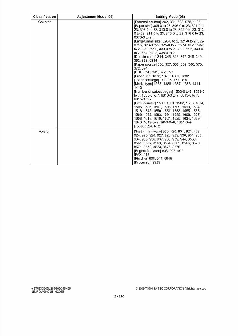
8/9/2019 Service manual E-studio 455
http://slidepdf.com/reader/full/service-manual-e-studio-455 238/670
e-STUDIO205L/255/305/355/455 © 2009 TOSHIBA TEC CORPORATION All rights reservedSELF-DIAGNOSIS MODES
2 - 210
Counter [External counter] 202, 381, 683, 975, 1126[Paper size] 305-0 to 23, 306-0 to 23, 307-0 to23, 308-0 to 23, 310-0 to 23, 312-0 to 23, 313-0 to 23, 314-0 to 23, 315-0 to 23, 316-0 to 23,6078-0 to 2[Large/Small size] 320-0 to 2, 321-0 to 2, 322-0 to 2, 323-0 to 2, 325-0 to 2, 327-0 to 2, 328-0to 2, 329-0 to 2, 330-0 to 2, 332-0 to 2, 333-0to 2, 334-0 to 2, 335-0 to 2
[Double count] 344, 345, 346, 347, 348, 349,352, 353, 9884[Paper source] 356, 357, 358, 359, 360, 370,372, 374[HDD] 390, 391, 392, 393[Fuser unit] 1372, 1378, 1380, 1382[Toner cartridge] 1410, 6977-0 to 4[Media type] 1385, 1386, 1387, 1388, 1411,1412[Number of output pages] 1530-0 to 7, 1533-0to 7, 1535-0 to 7, 6810-0 to 7, 6813-0 to 7,6815-0 to 7[Pixel counter] 1500, 1501, 1502, 1503, 1504,1505, 1506, 1507, 1508, 1509, 1510, 1514,1518, 1548, 1550, 1551, 1553, 1555, 1556,
1566, 1592, 1593, 1594, 1595, 1606, 1607,1608, 1613, 1619, 1624, 1625, 1634, 1639,1640, 1649-0~9, 1650-0~9, 1651-0~9[Job] 6852-0 to 2
Version [System firmware] 900, 920, 921, 922, 923,924, 925, 926, 927, 928, 929, 930, 931, 933,934, 935, 936, 937, 938, 939, 944, 8560,8561, 8562, 8563, 8564, 8565, 8566, 8570,8571, 8572, 8573, 8575, 8576[Engine firmware] 903, 905, 907[FAX] 915[Finisher] 908, 911, 9945[Processor] 9929
Classification Adjustment Mode (05) Setting Mode (08)

8/9/2019 Service manual E-studio 455
http://slidepdf.com/reader/full/service-manual-e-studio-455 239/670
© 2009 TOSHIBA TEC CORPORATION All rights reserved e-STUDIO205L/255/305/355/455SELF-DIAGNOSIS MODES
2 - 211
Maintenance [Equipment number] 976 [PM counter] 223, 251, 252, 375, 376, 5554,5555, 5562, 5563, 5568, 5569, 5576, 5577,5581, 5585[Telephone] 250[Error history] 253[FSMS] 999[Service notification] 702, 703, 707, 715, 716,717, 718, 719, 720, 721, 723, 767, 768, 769,770, 771, 772, 773, 774, 775, 776, 777, 778,
780, 781, 782, 783, 784, 785, 786, 787, 788,789, 790, 796, 1145, 8538, 9739, 9880, 9881[HTTP] 726, 727, 728, 729, 730, 731[Supply order] 732, 733, 734, 738, 739, 740,741, 742, 743, 744, 745, 746, 747, 748, 758,759, 760, 761, 762, 763, 765, 794, 795[Emergency Mode] 710, 711[Service call checking period] 1495[Remote update] 3630[PM support mode] 1150-0 to 8, 1151, 1158-0to 8, 1159, 1172-0 to 8, 1173, 1174-0 to 8,1175, 1182-0 to 8, 1183, 1198-0 to 8, 1199,1200-0 to 8, 1201, 1214-0 to 8, 1215, 1246-0to 8, 1247, 1250-0 to 8, 1251, 1268-0 to 8,1269, 1282-0 to 2, 1282-8, 1283, 1284-0 to 2,
1284-8, 1285, 1286-0 to 2, 1286-8, 1287,1290-0 to 2, 1290-8, 1291, 1292-0 to 2, 1292-8, 1293, 1294-0 to 2, 1294-8, 1295, 1298-0 to2, 1298-8, 1299, 1300-0 to 2, 1300-8, 1301,1302-0 to 2, 1302-8, 1303, 1306-0 to 2, 1306-8, 1307, 1308-0 to 2, 1308-8, 1309, 1310-0 to2, 1310-8, 1311, 1312-0 to 2, 1312-8, 1313,1314-0 to 2, 1314-8, 1315, 1316-0 to 2, 1316-8, 1317, 1320-0 to 2, 1320-8, 1321, 1322-0 to2, 1322-8, 1323, 1324-0 to 2, 1324-8, 1325,1328-0 to 2, 1328-8, 1329, 1330-0 to 2, 1330-8, 1331, 1336-0 to 8, 1337
General [Production line process] 9096 [Destination] 201, 701, 849[Line] 203[Data cloning] 9889[Unpacking date] 3612[Service history] 3619[PJL] 3797[USB] 3615, 3802[Direct printing] 3803[EWB] 3869[Raw printing] 8504[Cartridge empty] 8506[Print image position adjustment in secondaryscanning direction] 8508, 8509, 8510[Wide A4 Mode (PCL)] 8511[Number of jobs in batch processing] 8512[Outside erase] 8515, 8516[Scan setting] 8517, 8518, 8519, 8526, 8527
[No paper Message] 8524, 8525[Private printing] 8537[Easy setup] 9022[Counter/job list printing] 9954[Address book] 1125, 1476, 1477, 3508[New/old detection] 4549, 4555, 4556[SRAM] 1428, 4581, 4582[Power saving] 8543, 8544
Classification Adjustment Mode (05) Setting Mode (08)

8/9/2019 Service manual E-studio 455
http://slidepdf.com/reader/full/service-manual-e-studio-455 240/670
e-STUDIO205L/255/305/355/455 © 2009 TOSHIBA TEC CORPORATION All rights reservedSELF-DIAGNOSIS MODES
2 - 212
Other [Toner recycle] 280 [Trial and private] 259[Local I/F] 614[Partition] 662, 666, 667[Trial period] 673, 695, 798, 799[Banner] 678, 679, 680, 681[Database] 684, 685, 686[HDD] 670, 690, 691, 694, 1422, 1424, 1426,9379[Control panel] 692, 8532, 9051
[Equipment number] 995[Toner recycle] 838[Temperature/humidity] 839[Initialization] 693, 947, 9090[Mode setting] 949[Template] 1140, 3851[SRAM] 1428[TAT partition] 1118[Enhanced bold] 1149[User data management] 1472, 1473, 1474,1481, 1482, 1483[Limitation] 9829[e-Filing Access Mode] 1497[Inbound FAX] 1498[Card reader] 1772, 1773, 1774, 1775
[Administrator's password] 1778[FAX reception] 1926[File/Email] 1913, 1916[Extension fields] 1914[KS/KSMM setting] 1961[KS] 1960, 1963, 1964, 1965, 1966, 1967,1968, 1970, 1971, 1972, 1973, 1974, 1975,1976, 1977, 1978, 1979, 1980[KSSM] 1984, 1985, 1986, 1987, 1988, 1989,1990, 1991, 1992, 1993, 1994[Remote scanning] 3850, 9828[Filling box] 9882[Data cloning] 9889[Electronic licence key] 3840, 3841, 3842,3870
[FAX function] 3846, 3847, 3848, 3849[Hardcopy security printing] 9883[Disabling Media File Save] 9826
Classification Adjustment Mode (05) Setting Mode (08)

8/9/2019 Service manual E-studio 455
http://slidepdf.com/reader/full/service-manual-e-studio-455 241/670
© 2009 TOSHIBA TEC CORPORATION All rights reserved e-STUDIO205L/255/305/355/455 ADJUSTMENT
3 - 1
3. ADJUSTMENT
3.1 Adjustment Order This chapter mainly explains the procedures for image related adjustment. When replacing
components which have other specified instructions for adjustment, those specified instructions are to
be obeyed in priority. In the following diagram, the solid lines with arrow lead to essential adjustments,
while the dotted lines
lead to adjustments to be performed if necessary.
Fig. 3-1
Item to be adjusted
1
2
3
4
5
6
9
8
10
11
12
13
14
7
448, 449, 450, 452,
455, 457, 458, 460,
461, 462, 463, 469,
470, 471, 472, 473,
474
498
308
440, 441, 442, 443,444, 445
401
411
421
405
306
340
305
430
432
433
END
580
Item to be adjusted
Parts to be replaced
Transfer roller
Main charger grid
Photoconductive drum
Drum cleaning blade
Laser optical unitDeveloper material
3.2 Adjustment of the auto-toner sensor
Code in mode 05
200
3.3 Image dimensional adjustment
Code in mode 05
3.3.2 .Paper alignment at the registration roller
Items
3.3.4
Scanner
relatedadjustment
3.3.3Printer relatedadjustment
Order
[B] Primary scanning data laser writing start position
[C] Reproduction ratio of secondary scanning direction
[A] Reproduction ratio of primary scanning direction
[D] Secondary scanning data laser writing start position
[E] Primary scanning data laser writing start position at
duplexing
[A]
[B]
[C]
[D]
[E]
[F]
[G]
Image distortion
Reproduction ratio adjustment of the primary
scanning direction
Image position adjustment of the primary scanning
direction
Image position adjustment of the secondary
scanning direction
Top margin
Right margin
[H] Bottom margin
Reproduction ratio adjustment of the secondary
scanning direction
3.4.1 Automatic gamma adjustment
Code in mode 05
Adjust the image quality if necessary. (Chapter 3.3, 3.4, 3.5, 3.6, 3.7)

8/9/2019 Service manual E-studio 455
http://slidepdf.com/reader/full/service-manual-e-studio-455 242/670
e-STUDIO205L/255/305/355/455 © 2009 TOSHIBA TEC CORPORATION All rights reserved ADJUSTMENT
3 - 2
3.2 Adjustment of Auto-Toner Sensor When the developer material is replaced, adjust the auto-toner sensor in the following procedure.
<Procedure> (Adjustment Mode (05-200))
(1) Install the process unit into the equipment.
(2) While pressing [0] and [5] simultaneously, turn the power ON.
The following message will be displayed.
Fig. 3-2
(3) Key in code [200] and press the [START] button.
The display changes as follows.
Fig. 3-3
Notes:
• A indicates the controlled value of the auto-toner sensor output. Press the Up or Down buttonto change the value.
• B indicates the output voltage of the auto-toner sensor (2.30 V in the above case).
The drum, developer unit, etc. are in operation.
• C indicates the latest adjustment value.
(4) After about two minutes, the value B automatically starts changing.
Fig. 3-4
[0][5]
[POWER]
100%
TEST MODE
A3 A
[200] [START]
230%
128
200
TEST MODE
A3
128 A
B
C
230%
128
200
TEST MODE WAIT
A3
128

8/9/2019 Service manual E-studio 455
http://slidepdf.com/reader/full/service-manual-e-studio-455 243/670
© 2009 TOSHIBA TEC CORPORATION All rights reserved e-STUDIO205L/255/305/355/455 ADJUSTMENT
3 - 3
(5) After a short time, the value B becomes stable and the display changes as follows.
Fig. 3-5
(6) Check if the value B is within the range of 234 to 246 (the output voltage range of the auto-toner
sensor is 2.34 V to 2.46 V).
(7) If the value B is not within the range of 234 to 246, press the Up or Down button to adjust the
value manually.
Note:The relation between the button and the values A and B is as follows.
(8) Press the [ENTER] or [INTERRUPT] button.
The drum, developer unit, etc. are stopped and the following is displayed.
Fig. 3-6
(9) Turn the power OFF.
(10) Install the toner cartridge.
Button to be pressed Value A Value B
Up Increased Increased
Down Decreased Decreased
240%
128
200
ADJUSTMENT MODE
A3
150 A
B
[ENTER]
or
[INTERRUPT]
100%
TEST MODE
A3 A

8/9/2019 Service manual E-studio 455
http://slidepdf.com/reader/full/service-manual-e-studio-455 244/670
e-STUDIO205L/255/305/355/455 © 2009 TOSHIBA TEC CORPORATION All rights reserved ADJUSTMENT
3 - 4
3.3 Image Dimensional Adjustment
3.3.1 General description
There are several adjustment items in the image dimensional adjustment, as listed below. When
adjusting these items, the following adjustment order should strictly be observed.
Item to be adjusted Code in mode 05
1 Paper alignment at the registration roller 448, 449, 450, 452, 455, 457,458, 460, 461, 462, 463, 469,
470, 471, 472, 473, 474
2 Printer relatedadjustment
(a) Reproduction ratio of primary scanning direction(Fine adjustment of polygonal motor rotationspeed)
401
(b) Primary scanning data laser writing start position 411
(c) Reproduction ratio of secondary scanningdirection(Fine adjustment of main motor rotation speed)
421
(d) Secondary scanning data laser writing startposition
441, 440, 444, 443, 442, 445
(e) Primary scanning data laser writing start positionat duplexing
498
3 Scanner relatedadjustment
(a) Image distortion –
(b) Reproduction ratio of primary scanning direction 405
(c) Image location of primary scanning direction 306
(d) Reproduction ratio of secondary scanningdirection
340
(e) Image location of secondary scanning direction 305
(f) Top margin 430
(g) Right margin 432
(h) Bottom margin 433

8/9/2019 Service manual E-studio 455
http://slidepdf.com/reader/full/service-manual-e-studio-455 245/670

8/9/2019 Service manual E-studio 455
http://slidepdf.com/reader/full/service-manual-e-studio-455 246/670
e-STUDIO205L/255/305/355/455 © 2009 TOSHIBA TEC CORPORATION All rights reserved ADJUSTMENT
3 - 6
3.3.2 Paper alignment at the registration roller
The aligning amount is adjusted by using the following codes in Adjustment Mode (05).
Sub-code
(*1) 0: Long size 1: Middle size 2: Short size
(*2) 0: Long size 1: Middle size 2: Short size 3: Post card
(*3) 0: Long size of OHP film 1: Middle size of OHP film 2: Short size of OHP film
Notes:1. Long size: 330 mm or longer (13.0 inches or longer)
Middle size: 220-239 mm (8.7-12.9 inches)
Short size: 219 mm or shorter (8.6 inches or shorter)
2. The adjustment of “Post card” is for Japan only.
<Procedure>
(1) Perform the test print according to the following procedure.
(3) Perform the same procedure for all paper sources.
Paper
typeWeight
Upper
drawer
Lower
drawer
PFP upper
drawer
PFP lower
drawer LCF ADU
Bypass
feed
Plainpaper
64-80 g/m2
17-20 lb.
450 (*1) 452 (*1) 448 (*1) 449 (*1) 457 455 (*1) 458 (*1)
Thick
paper 1
81-105g/m2
21-28 lb.
469 (*1) 470 (*1) 471 (*1) 472 (*1) 473 474 (*1) 460 (*1)
Thickpaper 2
106-163g/m2
29-43 lb.
- - - - - - 461 (*1)
Thickpaper 3
164-209g/m2
44-55 lb.
- - - - - - 462 (*2)
OHP - - - - - - - 463 (*3)
(*4) 1: Single-sided grid pattern 3: Double-sided grid pattern
(2) Check if any transfer void is occurring. If
there is a transfer problem, try the values in
descending order as “31” “30” “29”···
until the transfer void disappears. At the
same time, confirm if any paper jam occurs.
Also, when the aligning amount has been
increased, this may increase the scrapingnoise caused by the paper and the Mylar
sheet as it is transported by the registration
roller. If this scraping noise is annoying, try to
decrease the value.
Fig. 3-8
(Code) [START] (Sub-code) [START][0][5]
[Power]
Current value
displayed
Enter new
value
[POWER]
OFF/ON
(Exit)
[Drawer
selection](*4) +[FAX]
(Test print)
[SET] or [INTERRUPT]
Stores in memory
(Not necessary for LCF)
5 0 m m
- 1 0
0 m m
Transfer void

8/9/2019 Service manual E-studio 455
http://slidepdf.com/reader/full/service-manual-e-studio-455 247/670
© 2009 TOSHIBA TEC CORPORATION All rights reserved e-STUDIO205L/255/305/355/455 ADJUSTMENT
3 - 7
Note:When paper thinner than specified is used, paper jams may occur frequently at the registration
section. In this case, it is advisable to change (or reduce) the aligning amount.
However, if the aligning amount is reduced too much, this may cause the shift of leading edge
position. So, when adjusting the aligning amount, try to choose the appropriate amount while
confirming the leading edge position is not shifted.
* As a tentative countermeasure, the service life of the feed roller can be extended by
increasing the aligning amount.

8/9/2019 Service manual E-studio 455
http://slidepdf.com/reader/full/service-manual-e-studio-455 248/670
e-STUDIO205L/255/305/355/455 © 2009 TOSHIBA TEC CORPORATION All rights reserved ADJUSTMENT
3 - 8
3.3.3 Printer related adjustment
The printer related adjustment is performed by using the printed out grid pattern.
Fig. 3-9 Grid pattern
Adjustment
ToleranceDetail of adjustment
A 200 ± 0.5mm P.3-9 "[A] Reproduction ratio of primary scanning direction (Fine adjustment ofpolygonal motor rotation speed (Printer))"
B 52 ± 0.5mm P.3-9 "[B] Primary scanning data laser writing start position (Printer)"
C 200 ± 0.5mm P.3-10 "[C] Reproduction ratio of secondary scanning direction (Fineadjustment of main motor rotation speed (Copier/Printer))"
D 52 ± 0.5mm P.3-11 "[D] Secondary scanning data laser writing start position"E 52 ± 0.5mm P.3-12 "[E] Primary scanning data laser writing start position at duplexing"
A21
6
1
B, E
D
6
3 0
2
C
1 0
F e e d i n g
d i r e c t i o n

8/9/2019 Service manual E-studio 455
http://slidepdf.com/reader/full/service-manual-e-studio-455 249/670

8/9/2019 Service manual E-studio 455
http://slidepdf.com/reader/full/service-manual-e-studio-455 250/670
e-STUDIO205L/255/305/355/455 © 2009 TOSHIBA TEC CORPORATION All rights reserved ADJUSTMENT
3 - 10
[C] Reproduction ratio of secondary scanning direction (Fine adjustment of main motor
rotation speed (Copier/Printer))
<Procedure>
(1) While pressing [0] and [5] simultaneously, turn the power ON. (Adjustment mode)
(2) Press [1] [FAX]. (A grid pattern with 10 mm squares is printed out. Use A3/LD from the lower
drawer (Refer to *).
(3) Check the grid pattern on the test chart printed out and measure the distance C from the 10thline at the leading edge of the paper to the 30th line of the grid pattern.
* Normally, the 1st line of the grid pattern is not printed.
(4) Check if the distance C is within 200±0.5 mm.
(5) If not, use the following procedure to change values and measure the distance C again.
(Adjustment Mode) (Key in code [421]) [START]
(Key in a value (acceptable values: 0 to 255))
[ENTER] or [INTERRUPT] (Stored in memory)
“100% A” is displayed
Press [1] [FAX] (A grid pattern is printed out.)* The larger the adjustment value is, the longer the distance C becomes (approx. 0.125 mm/
step).

8/9/2019 Service manual E-studio 455
http://slidepdf.com/reader/full/service-manual-e-studio-455 251/670
© 2009 TOSHIBA TEC CORPORATION All rights reserved e-STUDIO205L/255/305/355/455 ADJUSTMENT
3 - 11
[D] Secondary scanning data laser writing start position
This adjustment has to be performed for each paper source. (If there is no paper source, skip this step.)
The following table shows the order of the paper source to be adjusted, code, paper size and
acceptable values.
<Procedure>
(1) While pressing [0] and [5] simultaneously, turn the power ON. (Adjustment Mode)
(2) Press [1] ([3] for duplexing) [FAX]. (A grid pattern with 10 mm squares is printed out.)
(3) Check the grid pattern on the test chart printed out and measure the distance D from the leading
edge of the paper to the 6th line of the grid pattern.
* Normally, the 1st line of the grid pattern is not printed.
* At the duplexing, measure it on the top side of the grid pattern.
(4) Check if the distance D is within 52±0.5 mm.
(5) If not, use the following procedure to change values and measure the distance D again.
(Adjustment Mode) (Key in the code shown above) [START]
(Key in an acceptable value shown above)
[ENTER] or [INTERRUPT] (Stored in memory) “100% A” is displayed
Press [1] ([3] for duplexing) [FAX] (A grid pattern is printed out.)
* The larger the adjustment value is, the longer the distance D becomes (approx. 0.4 mm/step).
Order for
adjustmentPaper source Code Paper size
Acceptable
valueRemarks
1 Lower drawer 441 A3/LD 0 to 40
2 Upper drawer 440 A4/LT 0 to 15
3 PFP or LCF 444/443 A4/LT 0 to 15
4 Bypass feed 442 A4/LT 0 to 15
5 Duplexing 445 A3/LD 0 to 15 Paper fed from the lower drawer

8/9/2019 Service manual E-studio 455
http://slidepdf.com/reader/full/service-manual-e-studio-455 252/670
e-STUDIO205L/255/305/355/455 © 2009 TOSHIBA TEC CORPORATION All rights reserved ADJUSTMENT
3 - 12
[E] Primary scanning data laser writing start position at duplexing
Note:Make sure the first line of the grid pattern is printed out since the line is occasionally vanished.
[E-1] Adjustment for long-sized paper
<Procedure>
(1) While pressing [0] and [5] simultaneously, turn the power ON. (Adjustment Mode)
(2) Press [3] [FAX]. (A grid pattern with 10 mm squares is printed out. Use A3/LD from the lower
drawer (Refer to *).
(3) Check the grid pattern on the test print and measure the distance E from the left edge of the
paper to the 6th line of the grid pattern.
(4) Check if the distance E is within 52±0.5 mm.
(5) If not, use the following procedure to change values and measure the distance E again.
(Adjustment Mode) (Key in code [498]) [START] [0] [START]
(Key in a value (acceptable values: 0 to 255))
[ENTER] or [INTERRUPT] (Stored in memory) “100% A” is displayed.
Press [3] [FAX] (A grid pattern is printed out.)
* The larger the adjustment value is, the longer the distance E becomes (approx. 0.05 mm/
step).
[E-2] Adjustment for short-sized paper
<Procedure>
(1) While pressing [0] and [5] simultaneously, turn the power ON. (Adjustment Mode)
(2) Press [3] [FAX]. (A grid pattern with 10 mm squares is printed out. Use A4/LT from the upper
drawer.)
(3) Check the grid pattern on the test print and measure the distance E from the left edge of the
paper to the 6th line of the grid pattern.
(4) Check if the distance E is within 52±0.5 mm.
(5) If not, use the following procedure to change values and measure the distance E again.
(Adjustment Mode) (Key in the code [498]) [START] [1] [START]
(Key in a value (acceptable values: 0 to 255))
[ENTER] or [INTERRUPT] (Stored in memory).
“100% A” is displayed Press [3] [FAX] (A grid pattern is printed out.)
* The larger the adjustment value is, the longer the distance E becomes (approx. 0.05 mm/
step).

8/9/2019 Service manual E-studio 455
http://slidepdf.com/reader/full/service-manual-e-studio-455 253/670
© 2009 TOSHIBA TEC CORPORATION All rights reserved e-STUDIO205L/255/305/355/455 ADJUSTMENT
3 - 13
Remark:When the adjustment (05-421) is performed, the same adjustment for FAX (05-422) is
automatically and consecutively performed.
<Adjustment procedure summarization for A to E>
When the value is 1.
[0] [5] [Power ON] [1] ([3](05-445, 498) for duplexing) [FAX]
A: 05-401 (Lower drawer, A3/LD) 200±0.5 mm (0.125 mm/step)
B: 05-411 (Lower drawer, A3/LD) 52±0.5 mm (0.05 mm/step)
Key in the same value for 05-410.
C: 05-421 (Lower drawer, A3/LD) 200±0.5 mm (0.125 mm/step)
D: 05-440 (Lower drawer, A3/LD), 441 (Lower drawer, A4/LT), 444 (PFP, A4/LT),
443 (LCF, A4/LT), 442 (Bypass feed, A4/LT), 445 (Duplexing, A3/LD)
52±0.5 mm(0.4 mm/step)
E: 05-498-0 (Lower drawer, A3/LD),
498-1 (Lower drawer, A4/LT)) 52±0.5 mm (0.05 mm/step)

8/9/2019 Service manual E-studio 455
http://slidepdf.com/reader/full/service-manual-e-studio-455 254/670
e-STUDIO205L/255/305/355/455 © 2009 TOSHIBA TEC CORPORATION All rights reserved ADJUSTMENT
3 - 14
3.3.4 Scanner related adjustment
[A] Image distortion
Fig. 3-10
<Procedure>
(1) While pressing [0] and [5] simultaneously,
turn the power ON.
(2) Press [FAX] to make a copy of any image on
a sheet of A3/LD paper.
(3) Key in [308] and press the [START] button to
move the carriage to the adjustment position.
(4) Make an adjustment in the order of step 1
and 2.
• Step 1
- In case of A:
Tighten the mirror-3 adjustment screw
(CW).
- In case of B:
Loosen the mirror-3 adjustment screw
(CCW).
• Step 2
- In case of C:
Tighten the mirror-1 adjustment screw(CW).
- In case of D:
Loosen the mirror-1 adjustment screw
(CCW).
(5) Apply the screw locking agents to the
adjustment screws. (2 areas)
• Recommended screw lock agent
Manufacturer: Three Bond
Product name: 1401E
Fig. 3-11
Fig. 3-12
Feeding direction
Feeding direction
Step 1
A
Step 2
C
B
D
Carriage-2
Adjustment screw for the mirror-3 (Rear)
Adjustment screwfor the mirror-1 (Rear)
Carriage-1

8/9/2019 Service manual E-studio 455
http://slidepdf.com/reader/full/service-manual-e-studio-455 255/670
© 2009 TOSHIBA TEC CORPORATION All rights reserved e-STUDIO205L/255/305/355/455 ADJUSTMENT
3 - 15
[B] Reproduction ratio adjustment of the primary scanning direction
<Procedure>
(1) While pressing [0] and [5] simultaneously, turn the power ON (Adjustment Mode)
(2) Place a ruler on the original glass (along the direction from the rear to the front of the equipment).
(3) Press [FAX] to make a copy at the mode of A3 (LD), 100% and the lower drawer (Refer to *).
(4) Measure the distance A from 10 mm to 270 mm of the copied image of the ruler.
(5) Check if the distance A is within the range of 260±0.5 mm.
(6) If not, use the following procedure to change values and repeat the steps (3) to (5) above.
(Adjustment Mode) (Key in the code [405]) [START]
(Key in a value (acceptable values: 0 to 255))
Press the [ENTER] or the [INTERRUPT] button (stored in memory).
(“100% A” is displayed.)
* The larger the adjustment value is, the higher the reproduction ratio and the longer the
distance A become (approx. 0.125 mm/step).
Fig. 3-13
5 0
1 0 0
1
5 0
2 0 0
2 5 0
A
Feeding direction
Copied image of the ruler

8/9/2019 Service manual E-studio 455
http://slidepdf.com/reader/full/service-manual-e-studio-455 256/670
e-STUDIO205L/255/305/355/455 © 2009 TOSHIBA TEC CORPORATION All rights reserved ADJUSTMENT
3 - 16
[C] Image position adjustment of the primary scanning direction
<Procedure>
(1) While pressing [0] and [5] simultaneously, turn the power ON. (Adjustment Mode)
(2) Place a ruler on the original glass with its leading edge pushed against the rear side and its side
along the original scale on the left.
(3) Press [FAX] to make a copy at the mode of A3 (LD), 100% and the lower drawer (Refer to *).
(4) Measure the distance B from the left edge of the paper to 10 mm of the copied image of the ruler.
(5) Check if the distance B is within the range of 10±0.5 mm.
(6) If not, use the following procedure to change values and repeat the steps (3) to (5) above.
(Adjustment Mode) (Key in the code [306]) [START]
(Key in a value (acceptable values: 0 to 255))
Press the [ENTER] or the [INTERRUPT] button (stored in memory).
(“100% A” is displayed.)
* The smaller the adjustment value is, the more the image is shifted to the left and the distance
B becomes narrower (0.042 mm/step).
Fig. 3-14
5 0
1 0 0
1 5 0
2 0 0
B
Feeding direction
Copied image of the ruler

8/9/2019 Service manual E-studio 455
http://slidepdf.com/reader/full/service-manual-e-studio-455 257/670
© 2009 TOSHIBA TEC CORPORATION All rights reserved e-STUDIO205L/255/305/355/455 ADJUSTMENT
3 - 17
[D] Reproduction ratio adjustment of the secondary scanning direction
<Procedure>
(1) While pressing [0] and [5] simultaneously, turn the power ON. (Adjustment Mode)
(2) Place a ruler on the original glass with its leading edge pushed against the original scale on the
left.
(3) Press [FAX] to make a copy at the mode of A3 (LD), 100% and the lower drawer (Refer to *).
(4) Measure the distance C from 200 mm to 400 mm of the copied image of the ruler.
(5) Check if the distance C is within the range of 200±0.5 mm.
(6) If not, use the following procedure to change values and repeat steps (3) to (5) above.
(Adjustment Mode) (Key in the code [340]) [START]
(Key in a value (acceptable values: 63 to 193))
Press the [ENTER] or the [INTERRUPT] button (stored in memory).
(“100% A” is displayed.)
* The smaller the adjustment value is, the lower the reproduction ratio becomes (0.05 mm/
step).
Fig. 3-15
200 250 300 350 40050 100 150
C
Feeding direction
Copied image of the ruler

8/9/2019 Service manual E-studio 455
http://slidepdf.com/reader/full/service-manual-e-studio-455 258/670
e-STUDIO205L/255/305/355/455 © 2009 TOSHIBA TEC CORPORATION All rights reserved ADJUSTMENT
3 - 18
[E] Image position adjustment of the secondary scanning direction
<Procedure>
(1) While pressing [0] and [5] simultaneously, turn the power ON. (Adjustment Mode)
(2) Place a ruler on the original glass with its leading edge pushed against the original scale on the
left.
(3) Press [FAX] to make a copy at the mode of A3 (LD), 100% and the lower drawer (Refer to *).
(4) Measure the distance D from the leading edge of the paper to 10 mm of the copied image of the
ruler.
(5) Check if the distance D is within the range of 10±0.5 mm.
(6) If not, use the following procedure to change values and repeat the steps (3) to (5) above.
(Adjustment Mode) (Key in the code [305]) [START]
(Key in a value (acceptable values: 90 to 166))
Press the [ENTER] or the [INTERRUPT] button (stored in memory).
(“100% A” is displayed.)
* The larger the adjustment value is, the more the image is shifted to the trailing edge (0.13mm/step).
Fig. 3-16
10 20 30 40
D
Feeding direction
Copied image of the ruler

8/9/2019 Service manual E-studio 455
http://slidepdf.com/reader/full/service-manual-e-studio-455 259/670
© 2009 TOSHIBA TEC CORPORATION All rights reserved e-STUDIO205L/255/305/355/455 ADJUSTMENT
3 - 19
[F] Top margin
<Procedure>
(1) While pressing [0] and [5] simultaneously, turn the power ON. (Adjustment Mode)
(2) Open the original cover or RADF.
(3) Press [FAX] to make a copy at the mode of A3/LD, 100%, Text/Photo and the lower drawer
(Refer to *).
(4) Measure the blank area E at the leading edge of the copied image.
(5) Check if the blank area E is within the range of 3 ± 0.5 mm.
(6) If not, use the following procedure to change values and repeat the steps (3) to (5) above.
(Adjustment Mode) (Key in the code [430]) [START]
(Key in a value (acceptable values: 0 to 255))
Press the [ENTER] or the [INTERRUPT] button (stored in memory).
(“100% A” is displayed.)
* The larger the adjustment value is, the wider the blank area becomes (approx. 0.04 mm/
step).
Fig. 3-17
E
Feeding direction

8/9/2019 Service manual E-studio 455
http://slidepdf.com/reader/full/service-manual-e-studio-455 260/670
e-STUDIO205L/255/305/355/455 © 2009 TOSHIBA TEC CORPORATION All rights reserved ADJUSTMENT
3 - 20
[G] Right margin
<Procedure>
(1) While pressing [0] and [5] simultaneously, turn the power ON. (Adjustment Mode)
(2) Open the original cover or RADF.
(3) Press [FAX] to make a copy at the mode of A3/LD, 100%, Text/Photo and the lower drawer
(Refer to *).
(4) Measure the blank area F at the right side of the copied image.
(5) Check if the blank area F is within the range of 2±1.0 mm.
(6) If not, use the following procedure to change values and repeat the steps (3) to (5) above.
(Adjustment Mode) (Key in the code [432]) [START]
(Key in a value (acceptable values: 0 to 255))
Press the [ENTER] or the [INTERRUPT] button (stored in memory).
(“100% A” is displayed.)
* The larger the adjustment value is, the wider the blank area at the right side becomes
(approx. 0.04 mm/step).
Fig. 3-18
F
Feeding direction

8/9/2019 Service manual E-studio 455
http://slidepdf.com/reader/full/service-manual-e-studio-455 261/670
© 2009 TOSHIBA TEC CORPORATION All rights reserved e-STUDIO205L/255/305/355/455 ADJUSTMENT
3 - 21
[H] Bottom margin
<Procedure>
(1) While pressing [0] and [5] simultaneously, turn the power ON. (Adjustment Mode)
(2) Open the original cover or RADF.
(3) Press the [FAX] to make a copy at the mode of A3/LD, 100%, Text/Photo and the lower drawer
(Refer to *).
(4) Measure the blank area G at the trailing edge of the copied image.
(5) Check if the blank area G is within the range of 2±1.0 mm.
(6) If not, use the following procedure to change values and repeat the steps (3) to (5) above.
(Adjustment Mode) (Key in the code [433]) [START]
(Key in value (acceptable values: 0 to 255))
Press the [ENTER] or the [INTERRUPT] button (stored in memory).
(“100% A” is displayed.)
* The larger the adjustment value is, the wider the blank area at the trailing edge becomes
(approx. 0.04 mm/step).
Fig. 3-19
G
Feeding direction

8/9/2019 Service manual E-studio 455
http://slidepdf.com/reader/full/service-manual-e-studio-455 262/670
e-STUDIO205L/255/305/355/455 © 2009 TOSHIBA TEC CORPORATION All rights reserved ADJUSTMENT
3 - 22
3.4 Image Quality Adjustment (Copying Function)
3.4.1 Automatic gamma adjustment
When the reproduction of gradation is not appropriate, it can be corrected by performing this automatic
gamma adjustment. At the parts replacement and in case the gradation reproduction of the image is not
satisfactory, make this adjustment as described below.
(1) When unpacking or any of the following parts has been replaced, be sure to make this
adjustment:• Photoconductive drum • Developer material • Laser optical unit
• Transfer roller • Drum cleaning blade
• Main charger grid • SRAM board
(2) Be sure to perform this adjustment when changing the system ROM.
<Adjustment Mode (05)>
<Procedure>
(1) While pressing [0] and [5] simultaneously, turn the power ON. → Adjustment Mode
(2) Select the A4/LT drawer. Key in “10” and press the [FAX] button to print a “Patch chart for gamma
adjustment”.
(3) Place the patch chart for adjustment printed in step (2) face down on the original glass. Place the
chart aligning its black side of the gradation pattern against the original scale.
(4) Key in a code and press the [START] button.
(5) When the adjustment has finished normally, “ENTER” is shown. Press the [ENTER] button to
have the adjustment results reflected.
(To cancel the reflection of adjustment results, press the [CANCEL] button.)
In the case of an abnormal ending, “ADJUSTMENT ERROR” is shown.
Press the [CANCEL] button to clear the error display. When it is cleared, the control panel displaywill return to the ready state. Then, check if the patch chart on the original glass is placed in the
wrong direction or if it is placed inclined on the original glass, and then repeat step (3) and
afterward.
Code Item to be adjusted Contents
580 Automatic gammaadjustment
When the reproduction of gradation is not appropriate, it can be corrected byperforming this automatic gamma adjustment.

8/9/2019 Service manual E-studio 455
http://slidepdf.com/reader/full/service-manual-e-studio-455 263/670

8/9/2019 Service manual E-studio 455
http://slidepdf.com/reader/full/service-manual-e-studio-455 264/670
e-STUDIO205L/255/305/355/455 © 2009 TOSHIBA TEC CORPORATION All rights reserved ADJUSTMENT
3 - 24
3.4.3 Background adjustment
The density of the background can be adjusted as follows.
< Adjustment Mode (05) >
Make a test copy and compare the image obtained with the current settings; if necessary, make
adjustment using the following procedure.
<Procedure>
Procedure is same as that of P.3-23 "3.4.2 Density adjustment".
3.4.4 Sharpness adjustment
If you want to make copy images look softer or sharper, perform the following adjustment.
< Adjustment Mode (05) >
* The values in “( )” are the adjustment codes of the Custom Mode.
Make a test copy and compare the image obtained with the current settings; if necessary, make
adjustment using the following procedure.
Make a test copy and compare the image obtained with the current settings; if necessary, make
adjustment using the following procedure.
<Procedure>
Procedure is same as that of P.3-23 "3.4.2 Density adjustment".
Original mode
Item to be adjusted RemarksText/
PhotoPhoto Text
User
Custom
7033 7043 7034 7279 Automatic density mode The larger the value is, the lighter thebackground becomes.
Acceptable values:0 to 255 (Default: 128)
7041 7048 7042 7280 Manual density mode
Original mode
Item to be adjusted RemarksText/
PhotoPhoto Text
User
Custom
604 606 605 922 Sharpness adjustment The larger the value is, the sharperthe image becomes; while thesmaller the value is, the softer theimage becomes. The smaller the
value is, the less moire tends toappear. Acceptable values: 0 to 255 (Default: 128)

8/9/2019 Service manual E-studio 455
http://slidepdf.com/reader/full/service-manual-e-studio-455 265/670
© 2009 TOSHIBA TEC CORPORATION All rights reserved e-STUDIO205L/255/305/355/455 ADJUSTMENT
3 - 25
3.4.5 Setting range correction
The values of the background peak in the range correction can be switched to "varied" or "fixed" in the
following codes. If they are fixed, the range correction is performed with standard values.
The values of the background peak affect the reproduction of the background density.
< Adjustment Mode (05) >
Make a test copy and compare the image obtained with the current settings; if necessary, make
adjustment using the following procedure.
<Procedure>
Procedure is same as that of P.3-23 "3.4.2 Density adjustment".
3.4.6 Adjustment of smudged/faint text
The smudged/faint text can be set at the following codes.
< Adjustment Mode (05) >
<Procedure>
Procedure is same as that of P.3-23 "3.4.2 Density adjustment".
Original mode
Item to be adjusted RemarksText/
PhotoPhoto Text
User
Custom
7283 7285 7284 7236 Automatic density mode 0: Background peak / fixed1: Background peak / varied
7286 7288 7287 7237 Manual density mode
Original mode
Item to be adjusted RemarksText/
PhotoText
User
custom
648 649 925 Adjustment of smudged/faint spotted text
When the value increases, the smudged text isimproved.When the value decreases, the faint text isimproved.
Acceptable values: 0 to 4 (Default: 2)
Note:Remember the image specifications and lifespan of the replacing parts may not meetthe standard when the setting value ischanged from the default value.

8/9/2019 Service manual E-studio 455
http://slidepdf.com/reader/full/service-manual-e-studio-455 266/670
e-STUDIO205L/255/305/355/455 © 2009 TOSHIBA TEC CORPORATION All rights reserved ADJUSTMENT
3 - 26
3.4.7 Gamma balance adjustment
The density is adjusted by adjusting the gamma balance. The adjustment is performed by selecting its
density area from the following: low density, medium density and high density.
< Adjustment Mode (05) >
Note:Changing the adjustment setting influences the adjacent density area slightly.
E.g.: When the value of the medium density is larger, the adjacent areas in the low density and
high density range will become slightly darker.
<Procedure>
(1) While pressing [0] and [5] simultaneously, turn the power ON.
(2) Key in the code for an item to be adjusted and then press the [START] button.
(3) Key in a number for the density area to be adjusted (0, 1 or 2), and then press the [START]
button.
0: Low density 1: Medium density 2: High density
(4) Key in an adjustment value.
(To correct the keyed-in value, press the [CLEAR] button.)
(5) Press the [ENTER] or [INTERRUPT] button to store the value in memory. The equipment goes
back to the ready state.
(6) For resetting the value, repeat step (2) to (5).
(7) Press the [FAX] button and then the [START] button. Then perform test copying.
(8) If the desired image density has not been attained, repeat step (2) to (7).
Language and screenItem to be
adjustedRemarksText/
PhotoPhoto Text
User
custom
590-0 592-0 591-0 949-0 Low density The larger the value is, the density of theitem to be adjusted becomes darker. Acceptable values: 0 to 255. (Default: 128)590-1 592-1 591-1 949-1 Medium density
590-2 592-2 591-2 949-2 High density

8/9/2019 Service manual E-studio 455
http://slidepdf.com/reader/full/service-manual-e-studio-455 267/670
© 2009 TOSHIBA TEC CORPORATION All rights reserved e-STUDIO205L/255/305/355/455 ADJUSTMENT
3 - 27
3.4.8 Adjustment of image density
The image density level can be set at the following codes.
< Adjustment Mode (05) >
<Procedure>
(1) While pressing [0] and [5] simultaneously, turn the power ON.
(2) Key in the code “667” and press the [START] button.
(3) Key in the sub code (0, 1, 2, 3 or 4), and press the [START] button.
(4) Key in an adjustment value.
(To correct the keyed-in value, press the [CLEAR] button.)
(5) Press the [ENTER] or [INTERRUPT] button to store the value in memory. The equipment goes
back to the ready state.
(6) For resetting the value, repeat step (2) to (5).
(7) Press the [FAX] button and then the [START] button. Then perform test copying.
(8) If the desired image density has not been attained, repeat step (2) to (7).
3.4.9 Background offsetting adjustment for RADF
The background level for scanning originals with the RADF is adjusted when the background fogging at
the scanning of a manually-set original and an original used with the RADF is different. This is to adjust
the level of the background image removed when the scanning of the originals with the RADF is
performed.
<Adjustment Mode (05)>
<Procedure>
Procedure is same as that of P.3-23 "3.4.2 Density adjustment".
Code Item to be adjusted Remarks
667-0 to 4 Adjustment of image density When the value is decreased, text becomes lighter. Acceptable values: 0 to 10
Notes:1. Set not to reverse the large and small
number of the setting value correspondingto the sub code.Ex.) When the image density level for 667-0,667-1, 667-2, 667-3, and 667-4 is assumedto be "A","B", "C", "D", and "E" respectively,they should have the following correlation:
2. Remember that the image specificationsand life span of the replacing parts may notmeet the standard when the setting value ischanged from the default value.
Code Remarks
7025 The larger the value is, the lower the background density becomes. Acceptable values: 0 to 255 (Default: 128)
A B C D E

8/9/2019 Service manual E-studio 455
http://slidepdf.com/reader/full/service-manual-e-studio-455 268/670
e-STUDIO205L/255/305/355/455 © 2009 TOSHIBA TEC CORPORATION All rights reserved ADJUSTMENT
3 - 28
3.5 Image Quality Adjustment (Printing Function)
3.5.1 Adjustment of smudged/faint text
The smudged/faint text can be set at the following codes.
< Adjustment Mode (05) >
<Procedure>
(1) While pressing [0] and [5] simultaneously, turn the power ON.
(2) Key in a code and press the [START] button.
(3) Key in an adjustment value.
(To correct the keyed-in value, press the [CLEAR] button.)
(4) Press the [ENTER] or [INTERRUPT] button to store the value. The equipment goes back to the
ready state.
(5) Turn the power OFF and then back ON to perform printing job.
(6) If the desired text density has not been attained, repeat step (2) to (5).
LanguageRemarks
PS PCL XPS
654 655 656 When the value increases, the smudged text is improved. When the valuedecreases, the faint text is improved.
Acceptable values: 0 to 9 (Default: 5)

8/9/2019 Service manual E-studio 455
http://slidepdf.com/reader/full/service-manual-e-studio-455 269/670
© 2009 TOSHIBA TEC CORPORATION All rights reserved e-STUDIO205L/255/305/355/455 ADJUSTMENT
3 - 29
3.5.2 Adjustment of image density
The image density level can be set at the following codes.
< Adjustment Mode (05) >
<Procedure>
(1) While pressing [0] and [5] simultaneously, turn the power ON.
(2) Key in a code and press the [START] button.
(3) Key in the sub code (0, 1, 2, 3 or 4), and press the [START] button.
(4) Key in an adjustment value.
(To correct the keyed-in value, press the [CLEAR] button.)
(5) Press the [ENTER] or [INTERRUPT] button to store the value in memory. The equipment goes
back to the ready state.
(6) For resetting the value, repeat step (2) to (5).
(7) Turn the power OFF and then back ON to perform printing job.
(8) If the desired image density has not been attained, repeat step (2) to (7).
Toner mode
Item to be
adjustedRemarks
General Toner save
Hardcopy
security
printing
672-0 to 4 7352-0 to 4 7351-0 to 4 Adjustment ofimage density When the value is decreased, text becomeslighter. Acceptable values: 0 to 10
Notes:1. Set not to reverse the large and
small number of the setting valuecorresponding to the sub code.Ex.) When the image densitylevel for 672-0, 672-1, 672-2,672-3, and 672-4 is assumed tobe "A","B", "C", "D", and "E"respectively, they should have thefollowing correlation:
2. Remember that the imagespecifications and life span of thereplacing parts may not meet thestandard when the setting valueis changed from the default value.
A B C D E

8/9/2019 Service manual E-studio 455
http://slidepdf.com/reader/full/service-manual-e-studio-455 270/670
e-STUDIO205L/255/305/355/455 © 2009 TOSHIBA TEC CORPORATION All rights reserved ADJUSTMENT
3 - 30
3.5.3 Gamma balance adjustment
The density is adjusted by adjusting the gamma balance. The adjustment is performed by selecting its
density area from the following: low density, medium density and high density.
<Adjustment Mode (05)>
Note:Changing the adjustment setting influences the adjacent density area slightly.
E.g.: When the value of the medium density is larger, the adjacent areas in the low density and
high density range will become slightly darker.
<Procedure>
(1) While pressing [0] and [5] simultaneously, turn the power ON.(2) Key in the codes to be adjusted (language and screen) and press the [START] button.
(3) Key in the value corresponding to the density area to be adjusted (0, 1 or 2) and press the
[START] button.
0: Low density 1: Medium density 2: High density
(4) Key in the adjustment value. (To correct the value once keyed in, press the [CLEAR] button.)
(5) Press the [ENTER] or [INTERRUPT] button to store the value in memory. → The equipment
goes back to the ready state.
(6) For resetting the value, repeat step (2) to (5).
(7) Turn the power OFF and then back ON. Then perform printing.
(8) If the image density has not been attained, repeat step (2) to (7).
Color
mode
Language and screen Item to
be
adjusted
RemarksSmooth
(PS)
Detail
(PS)
Smooth
(PCL)
Detail
(PCL)
Smooth
(XPS)
Detail
(XPS)
Black 7315-0 7316-0 7317-0 7318-0 7319-0 7320-0 Low
density
The larger the value is,
the density of the itemto be adjustedbecomes darker.
Acceptable values: 0to 255(Default: 128)
7315-1 7316-1 7317-1 7318-1 7319-1 7320-1 Mediumdensity
7315-2 7316-2 7317-2 7318-2 7319-2 7320-2 Highdensity

8/9/2019 Service manual E-studio 455
http://slidepdf.com/reader/full/service-manual-e-studio-455 271/670
© 2009 TOSHIBA TEC CORPORATION All rights reserved e-STUDIO205L/255/305/355/455 ADJUSTMENT
3 - 31
3.6 Image Quality Adjustment (Scanning Function)
3.6.1 Gamma balance adjustment
The density is adjusted by adjusting the gamma balance. The adjustment is performed by selecting its
density area from the following: low density, medium density and high density.
<Adjustment Mode (05)>
Note:Changing the adjustment setting influences the adjacent density area slightly.
E.g.: When the value of the medium density is larger, the adjacent areas in the low density and
high density range will become slightly darker.
<Procedure>
(1) While pressing [0] and [5] simultaneously, turn the power ON.
(2) Key in the code corresponding to the desired original mode and press the [START] button.
(3) Key in the value corresponding to the density area to be adjusted (0, 1 or 2) and press the
[START] button.
0: Low density (L), 1: Medium density (M), 2: High density (H)
(4) Key in the adjustment value. (To correct the value once keyed in, press the [CLEAR] button.)
(5) Press the [ENTER] or [INTERRUPT] button to store the value in memory. The equipment goes
back to the ready state.
(6) For resetting the value, repeat step (2) to (5).(7) Turn the power OFF and then back ON. Then perform scanning.
(8) If the desired image has not been attained, repeat step (2) to (7).
Black
Gray
Scale
Item to be
adjustedRemarks
Original mode
Text/
PhotoText Photo
User
custom
880-0 881-0 882-0 7480-0 883-0 Low density The larger the value is, the density of theitem to be adjusted becomes darker.
Acceptable values: 0 to 255 (Default: 128)
880-1 881-1 882-1 7480-1 883-1 Medium density
880-2 881-2 882-2 7480-2 883-2 High density

8/9/2019 Service manual E-studio 455
http://slidepdf.com/reader/full/service-manual-e-studio-455 272/670
e-STUDIO205L/255/305/355/455 © 2009 TOSHIBA TEC CORPORATION All rights reserved ADJUSTMENT
3 - 32
3.6.2 Density adjustment
Adjusts the center density and the variation of density adjustment buttons.
<Adjustment Mode (05)>
<Adjustment Mode (05)>
<Procedure>
(1) While pressing [0] and [5] simultaneously, turn the power ON.
(2) Key in a code and press the [START] button.
(3) Key in an adjustment value (acceptable values: 0 to 255).
(To correct a value once keyed in, press the [CLEAR] button.)
(4) Press the [ENTER] or [INTERRUPT] button to store the value in memory. The equipment goes
back to the ready state.
(5) Turn the power OFF and then back ON. Then perform scanning.
(6) If the desired image quality has not been attained, repeat step (2) to (5).
Color
Mode
Original modeItem to be
adjustedRemarks
Text PhotoPrinted
image
User
custom
Color 8340 8341 8342 8380 Manual densitycenter value The larger the value is, the darker the imagebecomes. Acceptable values: 0 to 255 (Default: 128)
8344 8345 8346 8381 Manual densitylight step value
Sets the changing amount by 1 step at thedensity adjustment on the control panel.The larger the value is, the lighter the lightside becomes.
Acceptable values: 0 to 255 (Default: 20)
8348 8349 8350 8382 Manual densitydark step value
Sets the changing amount by 1 step at thedensity adjustment on the control panel.The larger the value is, the darker the darkside becomes.
Acceptable values: 0 to 255 (Default: 20)
Black
Gray
Scale
Item to be
adjustedRemarks
Original mode
Text/
PhotoText Photo
User
custom
845 846 847 7475 848 Manual densitycenter value
The larger the value is, the darker the imagebecomes.
Acceptable values: 0 to 255(Default: 128)860 861 862 7478 863 Automatic density

8/9/2019 Service manual E-studio 455
http://slidepdf.com/reader/full/service-manual-e-studio-455 273/670
© 2009 TOSHIBA TEC CORPORATION All rights reserved e-STUDIO205L/255/305/355/455 ADJUSTMENT
3 - 33
3.6.3 Judgment threshold for ACS
The judgment level is adjusted for the automatic identification of whether the original set on the glass is
black or color. Namely, this is to adjust the judgment level used when “Auto Color” is selected at color
modes.
<Adjustment Mode (05)>
<Procedure>:
The procedure is the same as that of P.3-32 "3.6.2 Density adjustment".
3.6.4 Sharpness adjustment
If you want to make scan images look softer or sharper, perform the following adjustment. The
adjustment can be made for each of the color modes and original modes independently.
<Adjustment Mode (05)>
Note:
You have to make adjustment by balancing between moire and sharpness.
<Procedure>
The procedure is the same as that of P.3-32 "3.6.2 Density adjustment".
Code Item to be adjusted Contents
1675 Judgment thresholdfor ACS
The larger the value is, the more an original tends to be judged as black evenat the Auto Color Mode. The smaller the value is, the more it tends to be
judged as color. Acceptable values: 0 to 255 (Default: 70)
Code Color mode Original mode Contents
1086 Full Color Text The larger the value is, the sharper the image becomes; whilethe smaller the value is, the softer the image becomes.The smaller the value is, the less moire tends to appear.The acceptable values are 0 to 255 (Defaullt : 128)
1087 Printed Image
1088 Photo
8375 User custom
840 Black Text/Photo
841 Text
842 Photo
7470 User custom
843 Gray Scale -

8/9/2019 Service manual E-studio 455
http://slidepdf.com/reader/full/service-manual-e-studio-455 274/670
e-STUDIO205L/255/305/355/455 © 2009 TOSHIBA TEC CORPORATION All rights reserved ADJUSTMENT
3 - 34
3.6.5 Setting range correction
The values of the background peak in the range correction can be switched to “varied” or “fixed” in the
following codes.
If they are fixed, the range correction is performed with standard values.
The values of the background peak affects the reproduction of the background density and the values
of the text peak affects that of the text density.
<Adjustment Mode (05)>
<Procedure>
The procedure is the same as that of P.3-32 "3.6.2 Density adjustment".
Black
Gray
ScaleItem to be adjusted Remarks
Original mode
Text/
PhotoText Photo
User
custom
7416 7417 7418 7425 7419 Range correction(Automatic densityadjustment)
0: Background peak - fixed1: Background peak - varied
7421 7422 7423 7426 7424 Range correction(Manual densityadjustment)
Color
Item to be adjusted RemarksOriginal mode
Text PhotoPrinted
Image
User
custom
8330 8331 8332 8334 Range correction (Automaticdensity adjustment)
0: Background peak - fixed1: Background peak - varied
8361 8362 8363 8365 Range correction (Manual densityadjustment)

8/9/2019 Service manual E-studio 455
http://slidepdf.com/reader/full/service-manual-e-studio-455 275/670
© 2009 TOSHIBA TEC CORPORATION All rights reserved e-STUDIO205L/255/305/355/455 ADJUSTMENT
3 - 35
3.6.6 Background adjustment
The adjustment level of background center value is adjusted. The control value of background
adjustment button is automatically adjusted to the same level as the adjusted center value.
For example, when the control value of background adjustment key ranges from 0 to 6, the background
center value (-2 to +2) is used to be the range from 6 to 14 accordingly.
<Adjustment Mode (05)>
<Procedure>
The procedure is the same as that of
P.3-32 "3.6.2 Density adjustment".
Code Original mode Remarks
1070 Text The smaller the value is, the background becomes lighter. Acceptable values: 0 to 50 (Default: 50)
1071 Printed Image
1072 Photo
8370 User custom
Before adjustment
After adjustment
0 1 2 3 4 5 6 7 8 9 10 11 12 13 14 15 16 17
+2 +1 0 -1 -2
-1 -2+2 +1 0

8/9/2019 Service manual E-studio 455
http://slidepdf.com/reader/full/service-manual-e-studio-455 276/670
e-STUDIO205L/255/305/355/455 © 2009 TOSHIBA TEC CORPORATION All rights reserved ADJUSTMENT
3 - 36
3.6.7 Fine adjustment of black density
The density of black side on scanned image is adjusted at color-scanning.
<Adjustment Mode (05)>
Note:Be careful for the value not to be too large since the gradation is reproduced worse in darker
side.
<Procedure>
The procedure is the same as that of P.3-32 "3.6.2 Density adjustment".
3.6.8 RGB conversion method selection
The color space conversion method of image is decided at color-scanning.
<Adjustment Mode (05)>
<Procedure>
The procedure is the same as that of P.3-32 "3.6.2 Density adjustment".
3.6.9 Adjustment of saturation
The saturation of the scanned image is adjusted for color-scanning.
<Adjustment Mode (05)>
<Procedure>
The procedure is the same as that of P.3-32 "3.6.2 Density adjustment".
Code Original mode Remarks
1075 Text The larger the value is, the black side of the image becomes darker. Acceptable values: 0 to 4 (Default: 0)
1076 Printed Image
1077 Photo
8371 User custom
Code Original mode Remarks1080 Text 0: sRGB, 1: AppleRGB, 2: ROMMRGB, 3: AdobeRGB
(Default: 0)1081 Printed Image
1082 Photo
8372 User custom
Code Original mode Remarks
8325 Text The larger the value is, the brighter the image becomes.The smaller the value is, the duller the image becomes.
Acceptable values: 0 to 255 (Default: 128)8326 Printed Image
8327 Photo
8373 User custom

8/9/2019 Service manual E-studio 455
http://slidepdf.com/reader/full/service-manual-e-studio-455 277/670
© 2009 TOSHIBA TEC CORPORATION All rights reserved e-STUDIO205L/255/305/355/455 ADJUSTMENT
3 - 37
3.6.10 Background processing offset adjustment
The density of background is adjusted.
<Adjustment Mode (05)>
<Procedure>
The procedure is the same as that of P.3-32 "3.6.2 Density adjustment".
Black
Item to be adjusted RemarksOriginal mode
Text/
PhotoPhoto
User
Custom
Gray
Scale
8400 8402 8404 8403 Background densityadjustment/ Automatic densityadjustment
The larger the value is, the lowerthe density of the imagebackground (low density section)becomes.The smaller the valueis, the higher the density of theimage background (low densitysection) becomes.Acceptablevalues: 0 to 255(Default: 128)
8405 8407 8409 8408 Background densityadjustment/ Manual densityadjustment
Color
Item to be adjusted RemarksOriginal mode
Text Photo
Printed
Image
User
Custom
8385 8386 8387 8389 Background densityadjustment/ Automatic densityadjustment
The larger the value is, the lowerthe density of the imagebackground (low density section)becomes.The smaller the valueis, the higher the density of theimage background (low densitysection) becomes.
Acceptable values: 0 to 255(Default: 128)
8390 8391 8392 8394 Background densityadjustment/ Manual densityadjustment
RADF
Item to be
adjustedRemarksBlack/
Gray
Scale
Color
7468 8395 Backgrounddensity processing/ RADF scanning
Adjusts the density of background for RADF scanning. Thelarger the value is, the lower the density of the backgroundand the low density section (e.g. light text or lines)becomes. The smaller the value is, the higher the densityof them becomes.
Acceptable values: 0 to 255(Default: 128)

8/9/2019 Service manual E-studio 455
http://slidepdf.com/reader/full/service-manual-e-studio-455 278/670
e-STUDIO205L/255/305/355/455 © 2009 TOSHIBA TEC CORPORATION All rights reserved ADJUSTMENT
3 - 38
3.7 Image Quality Adjustment (FAX Function)
3.7.1 Density adjustment
The center density and the density variation controlled by density adjustment keys can be adjusted as
follows.
<Adjustment Mode (05)>
* Since the gradation in this mode is reproduced in a binary image (black and white), this adjustment
should be a simple binary threshold adjustment.
<Procedure>
(1) While pressing [0] and [5] simultaneously, turn the power ON.
(2) Key in a code and press the [START] button.(3) Key in an adjustment value.
(To correct the value once keyed in, press the [CLEAR] button.)
(4) Press the [ENTER] or [INTERRUPT] button to store the value. → The equipment goes back to
the ready state.
(5) To set it again, repeat step (2) to (4).
(6) Turn the power OFF.
<Confirmation>
If possible, perform a Fax transmission and check the adjusted density with the image on the recipient's
side.
Color
mode
Original modeItem to be
adjusted RemarksText/Photo
Text * Photo
Black 714 700 710 Manual densitycenter value
The larger the value is, the darker the imagebecomes.
Acceptable values: 0 to 255 (Default: 128)729 - 725 Automatic density
mode

8/9/2019 Service manual E-studio 455
http://slidepdf.com/reader/full/service-manual-e-studio-455 279/670
© 2009 TOSHIBA TEC CORPORATION All rights reserved e-STUDIO205L/255/305/355/455 ADJUSTMENT
3 - 39
3.7.2 Adjustment of image density
The image density level can be set at the following codes.
< Adjustment Mode (05) >
<Procedure>
(1) While pressing [0] and [5] simultaneously, turn the power ON.
(2) Key in the code and press the [START] button.
(3) Key in the sub code and press the [START] button.
(4) Key in an adjustment value.
(To correct the keyed-in value, press the [CLEAR] button.)
(5) Press the [ENTER] or [INTERRUPT] button to store the value in memory. The equipment goes
back to the ready state.
(6) For resetting the value, repeat step (2) to (5).
(7) Turn the power OFF.
<Confirmation>
If possible, perform a Fax transmission and check the adjusted density with the image on the recipient's
side.
Code Item to be adjusted Remarks
678-0 to 4 Adjustment of image density When the value is decreased, text becomes lighter. Acceptable values: 0 to 10
Notes:1. Set not to reverse the large and small
number of the setting value correspondingto the sub code.Ex.) When the image density level for 667-0,678-1, 678-2, 678-3, and 678-4 is assumedto be "A","B", "C", "D", and "E" respectively,they should have the following correlation:
2. Remember that the image specificationsand life span of the replacing parts may notmeet the standard when the setting value ischanged from the default value.
A B C D E

8/9/2019 Service manual E-studio 455
http://slidepdf.com/reader/full/service-manual-e-studio-455 280/670

8/9/2019 Service manual E-studio 455
http://slidepdf.com/reader/full/service-manual-e-studio-455 281/670
© 2009 TOSHIBA TEC CORPORATION All rights reserved e-STUDIO205L/255/305/355/455 ADJUSTMENT
3 - 41
[A] Installation of the high-voltage transformer jig
The high-voltage transformer jig is composed of 2 cables and 1 adapter with a harness.
Attach them to the process unit as shown in the figure.
* Black cable (thick line): Use the screw for the jig. (M3 x 8)
* Red cable (thick line): Use the screw for the process unit.
* Adapter: Use the screw for the process unit.
Note:The adjustment may damage the drum. Therefore be sure to replace the drum with the one that
you brought (or the one for measurement) before starting the adjustment.
Fig. 3-20
(1) Open the automatic duplexing unit.
(2) Open the front cover and take off the toner
cartridge.
(3) Loosen 2 screws and pull out the process
unit.
Fig. 3-21
Change the drum
Screw
Black cable (thick line)
Harness
Screw
Screw
Adapter Red cable (thick line)
Disconnect 1 connector
Process unit

8/9/2019 Service manual E-studio 455
http://slidepdf.com/reader/full/service-manual-e-studio-455 282/670
e-STUDIO205L/255/305/355/455 © 2009 TOSHIBA TEC CORPORATION All rights reserved ADJUSTMENT
3 - 42
(4) Install the high-voltage transformer jig and fix
it with 2 screws.
Note:Be careful not to let the connector and the
harness be caught.
Fig. 3-22
(5) Fix the green cable of the high-voltage
transformer jig to the frame of the equipment.
Fig. 3-23
(6) Install the door switch jig.
(7) Take off the transfer roller unit.
(8) Close the automatic duplexing unit.
Fig. 3-24
Process unit
Green cable
Door switch jig

8/9/2019 Service manual E-studio 455
http://slidepdf.com/reader/full/service-manual-e-studio-455 283/670
© 2009 TOSHIBA TEC CORPORATION All rights reserved e-STUDIO205L/255/305/355/455 ADJUSTMENT
3 - 43
[B] Connection for developer bias adjustment
Fig. 3-25
[C] Connection for main charger adjustment
Fig. 3-26
Front cover switch
(-) terminal:Connect with the black cable (thin)
(+) terminal:Connect with theblack cable (thick )
Front cover switch
(-) terminal:Connect with the black cable (thin)
(+) terminal:Connect with the
red cable (thick )

8/9/2019 Service manual E-studio 455
http://slidepdf.com/reader/full/service-manual-e-studio-455 284/670
e-STUDIO205L/255/305/355/455 © 2009 TOSHIBA TEC CORPORATION All rights reserved ADJUSTMENT
3 - 44
[D] Connection the transfer bias, transfer cleaning bias(positive) and transfer cleaning
bias(negative) adjustment
Fig. 3-27
[E] Connection for separation charger adjustment
Fig. 3-28
Front cover opening/closing switch
(-) terminal:Connect with the black cable (thin)
(+) terminal:Connect with thered cable (thin )
Front cover opening/closing switch
(-) terminal:Connect with theblack cable (thin)
(+) terminal:Connect with thegray cable

8/9/2019 Service manual E-studio 455
http://slidepdf.com/reader/full/service-manual-e-studio-455 285/670
© 2009 TOSHIBA TEC CORPORATION All rights reserved e-STUDIO205L/255/305/355/455 ADJUSTMENT
3 - 45
[ 2 ] Operation
Note:When adjusting output of high-voltage transformer, make sure to use the high-voltage
transformer jig.
Connect the digital testers as described in “[1] Preparation”, and follow the procedure on the next
page to adjust the output from the main charger, developer bias charger, transfer charger and
separation charger.
Fig. 3-29
100% A3 ATEST MODE
100% XXX
YYY
A3TEST MODE
100% A3 ATEST MODE
Return to 1 to enter
the other adjustmentcode.
[0][5]
[POWER]
[UP] or [DOWN]: Adjust the value “YYY” to satisfy the following table.
[Digital keys]
[START]
: Enter the code.
[POWER] : OFF/ON
Code No.
Current set value
<Keys to press> <Display>
[SET]
or
[INTERRUPT]
: Adjusted value “YYY” is stored in memory.
1
Item Code
205
210
221
234
Adjustment value
e-STUOIO205L/255/305 e-STUOIO355/455
-377 5V
-502 5V
1600 55mV
-402 55mV
-377 5V
-516 5V
2300 55mV
-402 55mV
Developer bias
Main charger bias
Transfer bias
Separation bias
2083 1000 55mV 1800 55mVTransfer cleaning
bias(positive)
2084 -322 55mV -322 55mVTransfer cleaning
bias(negative)

8/9/2019 Service manual E-studio 455
http://slidepdf.com/reader/full/service-manual-e-studio-455 286/670
e-STUDIO205L/255/305/355/455 © 2009 TOSHIBA TEC CORPORATION All rights reserved ADJUSTMENT
3 - 46
3.8.2 Precautions
[ 1 ] Developer bias
Note for adjustment
Adjust the developer bias if fogging occurs over the entire image even though the main charger grid
voltage and toner density are appropriate. However, the following may occur if the developer bias is
lowered too much:
• Image contrast becomes low.
• Image is patchy or blurred.• The carrier in the developer material adheres to the photoconductive drum, causing scratches
around the cleaner.
[ 2 ] Transfer
Items to check before adjustment
Blotched image or poor transfer can be also caused by matters other than defective adjustment of
transfer output. Check the following items before adjusting the transfer charger. If there is no problem,
adjust the output of the transfer.
• Are the transfer roller unit, transfer roller and power supply spring properly installed? Is there any
foreign matter or damage on the transfer roller surface? Is the transfer guide deformed?
• Is the process unit properly installed? Is the developer magnetic brush in contact with the drum?
Is the process unit worked correctly? Is the toner density low?
• Is the copy paper fed straight? Is the copy paper abnormally moist?
• Is the rotation of the registration roller normal?
• Is the separation output different from the set value?
• Is the developer bias value an appropriate one?
Note for adjustment
When blotched image appear:
• If blotched image appear in halftone areas, lower the transfer output value. Remember that transfer
performance becomes low if the transfer output value is lowered too much.
When poor transfer occurs:
Increase the transfer output value under the following conditions. Remember that blotched image
appear if the transfer output value is increased too much.• Poor transfer occurs although the transfer roller unit, transfer roller and power supply spring are
properly installed and no abnormality exists on the appearance of the transfer roller.
• Thick paper has been frequently used.

8/9/2019 Service manual E-studio 455
http://slidepdf.com/reader/full/service-manual-e-studio-455 287/670
© 2009 TOSHIBA TEC CORPORATION All rights reserved e-STUDIO205L/255/305/355/455 ADJUSTMENT
3 - 47
[ 3 ] Separation
Items to check before adjustment
Poor paper separation from the drum can be also caused by matters other than defective adjustment of
the separation output. Check the following items before making an adjustment. If there is no problem,
adjust the output of the separation charger.
• Are the erasing needle and the power supply bracket dirty or dislocated?
• Is the mode selected properly according to the paper weight?
• Is the process unit installed properly? Is the developer magnetic brush in contact with the drum?
Is the process unit worked correctly? Is the toner density low?
• Is the copy paper fed straight? Is the copy paper abnormally moist?• Is the rotation of the registration roller normal?
• Is the output of the main charger normal?
• Is the developer bias an appropriate value?
• Is the transfer output different from the set value?
• Is the separation finger in contact with the drum surface?
Note for adjustment
When poor paper separation occurs:
Increase the separation output value under the following conditions. Note that poor transfer occurs if
the separation output value is too high.
• Poor separation occurs even though the separation needle is not dirty.
• Thin paper has been frequently used.
When poor transfer occurs:
• Decrease the separation output value when poor transfer occurs. Remember that the separation
performance becomes low if the separation output value is decreased too much.

8/9/2019 Service manual E-studio 455
http://slidepdf.com/reader/full/service-manual-e-studio-455 288/670
e-STUDIO205L/255/305/355/455 © 2009 TOSHIBA TEC CORPORATION All rights reserved ADJUSTMENT
3 - 48
3.9 Adjustment of the Scanner Section
3.9.1 Carriages
[A] Installing carriage wires
When replacing the carriage wires, refer illustrations below:
[Front side]
Fig. 3-30
[Rear side]
Fig. 3-31
Adjustment of the carriage wire tension is not necessary since a certain tension is applied to the
carriage wires by the tension springs.
Note:Make sure the tension applied to the wire is normal.
Carriage-2
Carriage wire
Bracket for carriage-1
Wire pulley
Idler pulley
Tension spring
Hook
Carriage-2
Carriage wire
Bracket for carriage-1
Hook
Wire pullTension spring
Idler pulley

8/9/2019 Service manual E-studio 455
http://slidepdf.com/reader/full/service-manual-e-studio-455 289/670
© 2009 TOSHIBA TEC CORPORATION All rights reserved e-STUDIO205L/255/305/355/455 ADJUSTMENT
3 - 49
[B] Adjusting carriages-1 and -2 positions
<Procedure>
(1) Move the carriage-2 toward the exit side.
(2) Loosen the screws fixing the front side pulley bracket, make the sections A and B of the carriage-
2 touch with the inside of the exit side frame and screw them up.
Fig. 3-32
(3) Put the carriage-1 on the rail, make the sections C and D of it touch with the inside of the exit
side frame and screw up the front/rear sides of the bracket to fix it.
Note:Make sure that the sections A and B of the carriage-2 touch with the exit side frame.
Fig. 3-33
AB
Carriage-2 Pulley bracket
[Rear] [Front]
Exit side frame
Carriage-1
[Rear] [Front]
Exit side frame
Bracket
Bracket

8/9/2019 Service manual E-studio 455
http://slidepdf.com/reader/full/service-manual-e-studio-455 290/670
e-STUDIO205L/255/305/355/455 © 2009 TOSHIBA TEC CORPORATION All rights reserved ADJUSTMENT
3 - 50
[C] Assembling carriage wires (Winding the wire around the wire pulley)
<Procedure>
(1) Pull the Ø3 ball terminal located at the center of the wire into a hole on the wire pulley. One end
of the wire with a hook attached comes to the outside.
(2) Wind the wires around the wire pulleys of the front and rear sides. The number of turns to be
wound are as follows:
• 3 turns toward the opposite side of the boss
• 3 turns toward the boss side
Note:Pay attention to the following when the wires are wound around the pulleys:
- Do not twist the wire.
- Wind the wires tightly so that they are in complete contact with the surface of the pulleys.
- Each turn should be pushed against the previously wound turn so that there is no space
between them.
Fig. 3-34
3 turns
3 turns 3 turns
3 turns
Ball terminal
Color: BlackColor: Silver
[Rear] [Front]
No space between turns
Ball terminal
HookHook

8/9/2019 Service manual E-studio 455
http://slidepdf.com/reader/full/service-manual-e-studio-455 291/670
© 2009 TOSHIBA TEC CORPORATION All rights reserved e-STUDIO205L/255/305/355/455 ADJUSTMENT
3 - 51
(3) After winding the wires around the pulleys, attach the wire holder jigs not to loosen the wires.
Notes:• When the wire holder jig is attached, make sure that the wire is not shifted or loosened.
• The wire should come out of the slot of the wire holder jig and be passed through between the
arm and the jig.
Fig. 3-35
Arm
Wire holder jig

8/9/2019 Service manual E-studio 455
http://slidepdf.com/reader/full/service-manual-e-studio-455 292/670
e-STUDIO205L/255/305/355/455 © 2009 TOSHIBA TEC CORPORATION All rights reserved ADJUSTMENT
3 - 52
3.9.2 Lens unit
[A] Replacing the lens unit
• The lens unit must not be readjusted and some part of its components must not be replaced in the
field since the unit is precisely adjusted. If any of the components is defective, replace the whole
unit.
• When replacing the unit, do not loosen or remove the 10 screws indicated with the arrows.
Fig. 3-36
• Handle the unit with care. Do not hold the lens and adjusted part (hold the unit as shown below).
Fig. 3-37

8/9/2019 Service manual E-studio 455
http://slidepdf.com/reader/full/service-manual-e-studio-455 293/670
© 2009 TOSHIBA TEC CORPORATION All rights reserved e-STUDIO205L/255/305/355/455 ADJUSTMENT
3 - 53
[B] Adjustment of the magnification ratio of the lens
Notes:• Perform this adjustment only when the lens unit is taken off or replaced.
• Make sure that the primary scanning reproduction ratio (printer section) is correct before this
adjustment.
(1) Place a ruler on the original glass (in the primary scanning direction) and make a copy on A4/LT-
sized paper at 100% reproduction ratio.
(3) If each mark on the rulers differs, perform the adjustment with the following procedures.
<Procedure>
(2) Compare the copied ruler with the actual
ruler.
Fig. 3-38
(1) Take off the original glass and lens cover.
(2) Loosen 4 screws fixing the lens unit.
Fig. 3-39
Feeding Direction
Actual ruler Copied ruler
Screw
Lens unit

8/9/2019 Service manual E-studio 455
http://slidepdf.com/reader/full/service-manual-e-studio-455 294/670
e-STUDIO205L/255/305/355/455 © 2009 TOSHIBA TEC CORPORATION All rights reserved ADJUSTMENT
3 - 54
(3) Slide the lens unit to the right or left direction using the marks on the lens base as a guide. (Slide
right when the copied ruler is magnified and slide left when the copied ruler is demagnified.)
The following table shows how the reproduction ratio difference between the copied ruler and
actual ruler corresponds to the movement amount of the lens unit.
Fig. 3-40
Note:Fine adjustment can be made in the “Reproduction ratio of primary scanning direction (printer)”.
on the copied ruler and actual ruler match.
(4) Tighten 4 screws fixing the lens unit.
(5) Attach the lens cover and original glass. Make a copy to confirm the reproduction ratio.
(6) Repeat the procedure 1 to 5 until the marks on the copied ruler and actual ruler match.
Reproduction-ratio error Movement amount of unit
0.1% 0.5 mm
0.2% 0.9 mm
0.3% 1.4 mm
0.4% 1.8 mm
0.5% 2.3 mm
0.6% 2.7 mm
0.7% 3.2 mm
0.8% 3.6 mm
0.9% 4.1 mm
1.0% 4.5 mm
Lens unit

8/9/2019 Service manual E-studio 455
http://slidepdf.com/reader/full/service-manual-e-studio-455 295/670
© 2009 TOSHIBA TEC CORPORATION All rights reserved e-STUDIO205L/255/305/355/455 ADJUSTMENT
3 - 55
3.10 Adjustment of the Paper Feeding System
Adjust the laser writing start position in the primary scanning direction with the lower drawer. (05-410,
05-411)
If deviation still occurs, perform the following:
3.10.1 Sheet sideways deviation caused by paper feeding
<Procedure>
Bypass feeding
The center of the printed image shifts to the frontside. Move the guide to the front side (Arrow
(A) direction in the lower figure).
The center of the printed image shifts to the rearside. Move the guide to the rear side (Arrow
(B) direction in the lower figure).
Fig. 3-41 Fig. 3-42
(1) Loosen the screw.
(2) Move the entire guide to the front or rear
side.
(3) Tighten the screw.
Fig. 3-43
Feeding direction
Center
[Rear]
[Front]
Feeding direction
Center
[Rear]
[Front]
(A) (B)

8/9/2019 Service manual E-studio 455
http://slidepdf.com/reader/full/service-manual-e-studio-455 296/670
e-STUDIO205L/255/305/355/455 © 2009 TOSHIBA TEC CORPORATION All rights reserved ADJUSTMENT
3 - 56
Drawer feeding
(1) Remove 1 screw and the stopper. And then
take off the drawer.
Fig. 3-44
(2) Lift up the drawer paper tray. Take off the
drawer tray upward by releasing it from a
stopper on the front side.
Fig. 3-45
(3) Move 1 screw to a position for the
adjustment screw. (If it is already moved,
skip this step.)
Fig. 3-46
Stopper
Stopper Drawer tray

8/9/2019 Service manual E-studio 455
http://slidepdf.com/reader/full/service-manual-e-studio-455 297/670
© 2009 TOSHIBA TEC CORPORATION All rights reserved e-STUDIO205L/255/305/355/455 ADJUSTMENT
3 - 57
(4) Loosen 2 screws.
Fig. 3-47
(5) Move the entire guide to the front or rear
side. Be sure to move the entire guide until
you can see 4 triangles.
(6) Tighten the 2 screws of the adjustment plate.
(7) Install the drawer tray, drawer and stopper.
* Adjustable range: 3 mm to the front side,4 mm to the rear side (Unit: 1 mm)
Fig. 3-48
Screw
(A)(B)
Scale

8/9/2019 Service manual E-studio 455
http://slidepdf.com/reader/full/service-manual-e-studio-455 298/670
e-STUDIO205L/255/305/355/455 © 2009 TOSHIBA TEC CORPORATION All rights reserved ADJUSTMENT
3 - 58
3.11 Adjustment of Developer Unit
3.11.1 Doctor-to-sleeve gap
Adjustment tool to use: Doctor-sleeve jig
<Procedure>
(1) Perform the adjustment code “05-280”.
(2) Take out the process unit from the equipment.
(3) Take out the developer unit from the process unit.
(4) Remove 2 screws and take off the developer
material cover and discharge the developer
material.
Note:Discharge the developer material from the
rear side, being careful not to let it be
scattered on the gear.
Fig. 3-49
(5) Turn the adjustment screw to widen the gap
so that the jig can be inserted in it.
(Turning the screw clockwise widens the
gap)
Fig. 3-50
Developer material cover
Screw

8/9/2019 Service manual E-studio 455
http://slidepdf.com/reader/full/service-manual-e-studio-455 299/670
© 2009 TOSHIBA TEC CORPORATION All rights reserved e-STUDIO205L/255/305/355/455 ADJUSTMENT
3 - 59
(6) Insert the gauge with the thickness “0.45” of
the doctor sleeve jig into the gap between
the developer sleeve and doctor blade after
lifting up the toner scattering prevention
sheet.
Adjust the screws with the doctor blade to
push the doctor sleeve jig lightly.
Fig. 3-51
(7) Insert the gauge “0.40” of the doctor sleeve
jig into the gap between the developer
sleeve and doctor blade. Confirm that the jig
moves smoothly to the front and rear side,
and the gauge “0.50” cannot be inserted into
the gap.
Fig. 3-52
(8) Confirm that the side seals are attached on
the toner scattering prevention sheet.
Fig. 3-53
ScrewDoctor sleeve jig
Toner scatteringprevention sheet
Developer sleeve
Doctor sleeve jig
Side seal
Toner scatteringprevention sheet

8/9/2019 Service manual E-studio 455
http://slidepdf.com/reader/full/service-manual-e-studio-455 300/670
e-STUDIO205L/255/305/355/455 © 2009 TOSHIBA TEC CORPORATION All rights reserved ADJUSTMENT
3 - 60
(9) Attach the developer material cover and
tighten 2 screws.
Notes:1. After the developer material has been
replaced, adjust the auto-toner sensor.
(See P.3-2 "3.2 Adjustment of Auto-
Toner Sensor".)
2. When installing the developer unit upper
cover, make sure that the side seal
comes between the developer unit upper
cover and rubber seal on the cover.
Fig. 3-54
Fig. 3-55
Developer material cover
Side seal
Rubber seal
Developer unitupper cover

8/9/2019 Service manual E-studio 455
http://slidepdf.com/reader/full/service-manual-e-studio-455 301/670

8/9/2019 Service manual E-studio 455
http://slidepdf.com/reader/full/service-manual-e-studio-455 302/670
e-STUDIO205L/255/305/355/455 © 2009 TOSHIBA TEC CORPORATION All rights reserved ADJUSTMENT
3 - 62
[B] Adjustment
If the pins cannot be fitted into the holes, perform the adjustment according to the following procedure.
(1) Remove the right-hand hinge screw at the
rear side.
Fig. 3-59
(2) Loosen the left-hand hinge screw at the rear
side.
Fig. 3-60
(3) Loosen the hinge screws at the front side.
Fig. 3-61

8/9/2019 Service manual E-studio 455
http://slidepdf.com/reader/full/service-manual-e-studio-455 303/670
© 2009 TOSHIBA TEC CORPORATION All rights reserved e-STUDIO205L/255/305/355/455 ADJUSTMENT
3 - 63
(4) Position the pins with the holes on the RADF
by moving it so that the pins fit into the holes
when the RADF is closed.
Fig. 3-62
(5) Tighten the left-hand hinge screw at the rear
side.
Fig. 3-63
(6) Loosen the hole position adjustment screws
on the right hand side.
Fig. 3-64

8/9/2019 Service manual E-studio 455
http://slidepdf.com/reader/full/service-manual-e-studio-455 304/670
e-STUDIO205L/255/305/355/455 © 2009 TOSHIBA TEC CORPORATION All rights reserved ADJUSTMENT
3 - 64
(7) Match the screw hole positions.
Fig. 3-65
(8) Install the right-hand hinge screw at the rear
side.
Fig. 3-66
(9) Loosen the hinge screws at the front side.
Fig. 3-67

8/9/2019 Service manual E-studio 455
http://slidepdf.com/reader/full/service-manual-e-studio-455 305/670
© 2009 TOSHIBA TEC CORPORATION All rights reserved e-STUDIO205L/255/305/355/455 ADJUSTMENT
3 - 65
(10) Place the platen sheet on the original glass
and align it to the top left corner.
Close the RADF gently and open it to check
if the platen sheet is attached properly.
Fig. 3-68

8/9/2019 Service manual E-studio 455
http://slidepdf.com/reader/full/service-manual-e-studio-455 306/670
e-STUDIO205L/255/305/355/455 © 2009 TOSHIBA TEC CORPORATION All rights reserved ADJUSTMENT
3 - 66
3.12.2 Adjustment of RADF height
Note:Check if the image adjustment for the equipment is performed properly before this adjustment of
the RADF.
[A] Checking
(1) Close the RADF.
(2) Light the exposure lamp.• Turn the power ON while pressing [0] and [3] simultaneously.
• Key in [267] and then press the [START] button. The exposure lamp is turned ON for a given
length of time.
(3) Visually check the gap between platen guide holder "A" and upper surface of the original glass
"B" from the left hand side of the equipment. If the value is not within the tolerance, perform the
adjustment according to the following procedure.
[Tolerance of the gap]
Rear side: 0 - 0.5 mm
Front side: 0 mm
Fig. 3-69
0 . 2 - 0 . 5
m m
0 m m
B
A
B
A

8/9/2019 Service manual E-studio 455
http://slidepdf.com/reader/full/service-manual-e-studio-455 307/670
© 2009 TOSHIBA TEC CORPORATION All rights reserved e-STUDIO205L/255/305/355/455 ADJUSTMENT
3 - 67
[B] Adjustment
(1) Close the RADF.
(2) Adjust it by turning the adjustment screws on the hinges.
• Adjust the height on the rear side by means of the screw on the hinge on the feed side of the
RADF.
Turn it clockwise ................. Heightened
Turn it counterclockwise ......Lowered
Fig. 3-70
• Adjust the gap on the rear side by means of the screw on the hinge on the feed side of the
RADF.
Turn it clockwis ....................Lowered
Turn it counterclockwise ......Heightened
Fig. 3-71

8/9/2019 Service manual E-studio 455
http://slidepdf.com/reader/full/service-manual-e-studio-455 308/670
e-STUDIO205L/255/305/355/455 © 2009 TOSHIBA TEC CORPORATION All rights reserved ADJUSTMENT
3 - 68
3.12.3 Adjustment of skew
Note:Check if the image adjustment for the equipment is performed properly before this adjustment of
the RADF. Also, the RADF position and height shall be adjusted properly.
[A] Checking
Check the image using the chart (original) with vertical and horizontal lines in the following procedure.
Fig. 3-72 Chart (Original)
Simplex copying:
(1) Place the chart provided as an original with its face up on the original tray of the RADF, select [1
Sided -> 1 Sided] and press the [START] button.
(2) Superimpose the chart on the copy and check the inclination of the copy image.
Duplex copying:
(1) Place the chart provided as an original with its face up on the original tray of the RADF, select [2
Sided -> 2 Sided] and press the [START] button.
(2) Superimpose the chart on the copy and check the inclination of the copy image.

8/9/2019 Service manual E-studio 455
http://slidepdf.com/reader/full/service-manual-e-studio-455 309/670
© 2009 TOSHIBA TEC CORPORATION All rights reserved e-STUDIO205L/255/305/355/455 ADJUSTMENT
3 - 69
[B] Adjustment
Simplex copying:
(1) Shift the aligning plate with the scale as the guide shown in the figure below to adjust the skew.
Fig. 3-73
(2) If the image skew is "C" as shown in the figure below, shift the aligning plate in the direction of"+", and if "D", shift it to "-".
Fig. 3-74Fig. 3-75
Shift the aligning plate in the direction of "+". Shift the aligning plate in the direction of "-".
C
D

8/9/2019 Service manual E-studio 455
http://slidepdf.com/reader/full/service-manual-e-studio-455 310/670
e-STUDIO205L/255/305/355/455 © 2009 TOSHIBA TEC CORPORATION All rights reserved ADJUSTMENT
3 - 70
Duplex copying:
(1) Shift the aligning plate with the scale as the guide shown in the figure below to adjust the skew.
Fig. 3-76
(2) If the image skew is "C" as shown in the figure below, shift the aligning plate in the direction of "-
", and if "D", shift it to "+".
Fig. 3-77 Fig. 3-78
Shift the aligning plate in the direction of "-". Shift the aligning plate in the direction of "+".
C
D

8/9/2019 Service manual E-studio 455
http://slidepdf.com/reader/full/service-manual-e-studio-455 311/670
© 2009 TOSHIBA TEC CORPORATION All rights reserved e-STUDIO205L/255/305/355/455 ADJUSTMENT
3 - 71
3.12.4 Adjustment of the leading edge position
Note:Check if the image adjustment for the equipment is performed properly before this adjustment of
the RADF. Also, the RADF position and height shall be adjusted properly.
[A] Checking
Check the image using the chart (original) with vertical and horizontal lines in the following procedure.
Simplex copying:
(1) Place the chart provided as an original with its face up on the original tray of the RADF, select [1
Sided -> 1 Sided] and press the [START] button.
(2) Superimpose the chart on the copy and check the leading edge E of the chart and F of the copy.
Duplex copying:
(1) Place the chart provided as an original with its face up on the original tray of the RADF, select [2
Sided -> 2 Sided] and press the [START] button.
(2) Superimpose the chart on the copy and check the leading edge E of the chart and F of the copy.
Fig. 3-79 Chart (Original)Fig. 3-80 Copy
E F

8/9/2019 Service manual E-studio 455
http://slidepdf.com/reader/full/service-manual-e-studio-455 312/670
e-STUDIO205L/255/305/355/455 © 2009 TOSHIBA TEC CORPORATION All rights reserved ADJUSTMENT
3 - 72
[B] Adjustment
Simplex copying:
(1) Turn the power ON while pressing [0] and [5] simultaneously, key in [365] and then press the
[START] button.
(2) Enter the value.
• If the leading edge (F) margin of the copy image is larger than the (E) margin of the chart,
enter a value smaller than the current one.
Note:Changing one value shifts the copy image by 0.2 mm.
• If the leading edge (F) margin of the copy image is smaller than the (E) margin of the chart,
enter a value larger than the current one.
Note:Changing one value shifts the copy image by 0.2 mm.
(3) Press the [ENTER] button.
Duplex copying:
(1) Turn the power ON while pressing [0] and [5] simultaneously, key in [366] and then press the[START] button.
(2) Enter the value.
• If the leading edge (F) margin of the copy image is larger than the (E) margin of the chart,
enter a value smaller than the current one.
Note:Changing one value shifts the copy image by 0.2 mm.
• If the leading edge (F) margin of the copy image is smaller than the (E) margin of the chart,
enter a value larger than the current one.
Note:Changing one value shifts the copy image by 0.2 mm.
(3) Press the [ENTER] button.

8/9/2019 Service manual E-studio 455
http://slidepdf.com/reader/full/service-manual-e-studio-455 313/670
© 2009 TOSHIBA TEC CORPORATION All rights reserved e-STUDIO205L/255/305/355/455 ADJUSTMENT
3 - 73
3.12.5 Adjustment of horizontal position
Note:Check if the image adjustment for the equipment is performed properly before this adjustment of
the RADF. Also, the RADF position and height shall be adjusted properly.
[A] Checking
Check the image using the chart (original) with a center line in the following procedure.
(1) Place the chart provided as an original with its face up on the original tray of the RADF.(2) Press the [START] button.
(3) Fold the copy in half and check if the center line is misaligned.
[B] Adjustment
(1) Turn the power ON while pressing [0] and [5] simultaneously.
(2) Key in [358] and then press the [START] button.
• If the center line of the copy image is shifted to the front side of the equipment, enter a value
larger than the current one.
Note:Changing one value shifts the copy image by 0.042 mm.
Fig. 3-81
• If the center line of the copy image is shifted to the rear side of the equipment, enter a value
smaller than the current one.
Note:Changing one value shifts the copy image by 0.042 mm.
Fig. 3-82
(3) Press the [ENTER] button.
G
H

8/9/2019 Service manual E-studio 455
http://slidepdf.com/reader/full/service-manual-e-studio-455 314/670
e-STUDIO205L/255/305/355/455 © 2009 TOSHIBA TEC CORPORATION All rights reserved ADJUSTMENT
3 - 74
3.12.6 Adjustment of copy ratio
Note:Check if the image adjustment for the equipment is performed properly before this adjustment of
the RADF. Also, the RADF position and height shall be adjusted properly.
[A] Checking
Check the image using the chart (original) with vertical and horizontal lines in the following procedure.
(1) Place the chart provided as an original with its face up on the original tray of the RADF.(2) Press the [START] button.
(3) Superimpose the chart on the copy and check the image dimension “I”.
[B] Adjustment
(1) Turn the power ON while pressing [0] and [5] simultaneously.
(2) Key in [357] and then press the [START] button.
• If the copy image dimension “I” is larger than the chart dimension, enter a value smaller than
the current one.
• If the copy image dimension “I” is smaller than the chart dimension, enter a value larger than
the current one.
Fig. 3-83
(3) Press the [ENTER] button.
I

8/9/2019 Service manual E-studio 455
http://slidepdf.com/reader/full/service-manual-e-studio-455 315/670
© 2009 TOSHIBA TEC CORPORATION All rights reserved e-STUDIO205L/255/305/355/455 ADJUSTMENT
3 - 75
3.12.7 Adjustment of RADF opening/closing sensor
Adjust the bracket position so that the sensor is turned ON when the height “A” becomes 100 mm or
less (within the empty weight falling limit).
Fig. 3-84
Fig. 3-85
A

8/9/2019 Service manual E-studio 455
http://slidepdf.com/reader/full/service-manual-e-studio-455 316/670
e-STUDIO205L/255/305/355/455 © 2009 TOSHIBA TEC CORPORATION All rights reserved ADJUSTMENT
3 - 76
3.13 Adjustment of the Finisher (MJ-1025)
3.13.1 Adjusting the folding position (Electrical system (Finisher/Saddle
unit))
The folding position is adjusted by matching it with the stapling position.
If you have replaced the finisher controller PCB, you must transfer the existing settings to the new PCB.
Perform the following if the folding position must be adjusted for some reason.
Note:Both the folding and stapling positions may deviate for some type of paper.
In such a case, change the “middle stapling position” in the user mode of the host machine.
<Procedure>
(1) Turn OFF the power of the equipment.
(2) Set SW1 on the finisher controller PCB as follows:
Fig. 3-86
(3) Turn ON the power of the equipment while [0] button and [8] button are pressed simultaneously.
(4) Adjust the folding position by pressing the PSW1 or PSW2 on the finisher controller PCB a
required number of times. Pressing the switch once moves the folding position about 0.16 mm.
• To move the folding position in the “-” direction, press the PSW1.
• To move the folding position in the “+” direction, press the PSW2.
• Pressing the PSW1 and PSW2 at the same time clears the adjustment value.
Fig. 3-87
(5) When adjustment of the folding position is complete, set all bits of the SW1 on the finisher
controller PCB to OFF.
(6) Enter the bind mode of the host machine and check whether the folding position is adjusted
properly. If adjusted improperly, adjust the folding position again.
1 2 3 5 6 7 84
ON
+ direction- direction

8/9/2019 Service manual E-studio 455
http://slidepdf.com/reader/full/service-manual-e-studio-455 317/670
© 2009 TOSHIBA TEC CORPORATION All rights reserved e-STUDIO205L/255/305/355/455 ADJUSTMENT
3 - 77
3.13.2 Adjusting the sensor output (Electrical system (Puncher unit;
option))
Perform the following when the punch controller PCB, horizontal registration sensor (photosensor PCB/
LED PCB), or waste full sensor (waste full photosensor PCB/waste full LED PCB) has been replaced.
<Procedure>
(1) Turn OFF the power of the equipment.
(2) Shift bits 1 through 4 on the punch controller PCB as follows:
Fig. 3-88
(3) Turn ON the power of the equipment while [0] button and [8] button are pressed simultaneously.
(4) Press SW1002 or SW1003 on the punch controller PCB. A press will automatically adjust thesensor output.
• The adjustment is over when all LEDs on the punch controller PCB are ON: LED 1001,
LED1002, LED1003.
(5) Shift all bits of DIPSW1001 to OFF.
1 2 3 4
ON

8/9/2019 Service manual E-studio 455
http://slidepdf.com/reader/full/service-manual-e-studio-455 318/670
e-STUDIO205L/255/305/355/455 © 2009 TOSHIBA TEC CORPORATION All rights reserved ADJUSTMENT
3 - 78
3.13.3 Registering the number of punch hole (Electrical system
(Puncher unit; option))
Perform the following to register the type of puncher unit (number of holes) used to the IC on the punch
controller PCB for identification by the finisher. Be sure to register the type whenever you have replaced
the punch controller PCB.
<Procedure>.
(1) Turn OFF the power of the equipment.
(2) Set bits of 1 through 4 on the DIPSW1001 on the punch controller PCB as follows:
Fig. 3-89
(3) Turn ON the power of the equipment while [0] button and [8] button are pressed simultaneously.
(4) Press SW1002 on the punch controller PCB to select the appropriate number of punch holes.
• Each press on SW1002 moves the selection through the following (repeatedly from top to
bottom).
(5) Press SW1003 on the punch controller PCB twice. The presses will store the selected number of
punch holes on the punch controller PCB.
• A single press on SW1003 will cause the LED indication to flash; another press on SW1003
will cause the indication to remain ON to indicate the end of registration.
(6) Shift all bits of DIPSW1001 to OFF.
Number of punch holes LED1001 LED1002 LED1003
2 holes (E) ON OFF OFF
2/3 holes (N) ON ON OFF
4 holes (F) OFF ON OFF
4 holes (S) OFF OFF ON
1 2 3 4
ON

8/9/2019 Service manual E-studio 455
http://slidepdf.com/reader/full/service-manual-e-studio-455 319/670

8/9/2019 Service manual E-studio 455
http://slidepdf.com/reader/full/service-manual-e-studio-455 320/670
e-STUDIO205L/255/305/355/455 © 2009 TOSHIBA TEC CORPORATION All rights reserved ADJUSTMENT
3 - 80
3.14 Adjustment of the Finisher (MJ-1024)
Note:Before performing each adjustment, make sure that all covers (incl. those of the finisher and host
machine) are closed. Otherwise, the power is not supplied to the finisher and the adjustment may
not be performed properly.
3.14.1 Adjusting the alignment position (Finisher unit)
Perform this adjustment after replacing the finisher controller PC board or when the alignment positionmust be changed for some reason.
(1) Remove the rear cover of the finisher unit.
(2) Check that the power is OFF and set SW104 on the finisher controller PC board as follows
according to the paper used for adjustment.
Fig. 3-91
(3) Turn ON the power of the equipment while [0] button and [8] button are pressed simultaneously.
(4) Press SW103 on the finisher controller PC board.
• When SW103 is pressed, the swing guide opens and the alignment plate moves to prescribed
position.
(5) Place ten sheets of A4/LT paper between the alignment plates and push them against the
stopper.
(6) Press SW101 or SW102 on the finisher controller PC board and push the alignment plate against
the paper.
• When SW101 is pressed, alignment plate moves 0.42 mm forward.
• When SW102 is pressed, alignment plate moves 0.42 mm backward.(7) When adjustment is complete, remove paper and press SW103 on the finisher controller PC
board once to store the adjustment in memory.
(8) Turn OFF all bits of finisher controller PC board SW104.
(9) Turn OFF the power and install the rear cover of the finisher unit.
ON
1 2 3 4 5 6 7 8
ON
1 2 3 4 5 6 7 8
A4 paper LT paper

8/9/2019 Service manual E-studio 455
http://slidepdf.com/reader/full/service-manual-e-studio-455 321/670
© 2009 TOSHIBA TEC CORPORATION All rights reserved e-STUDIO205L/255/305/355/455 ADJUSTMENT
3 - 81
3.14.2 Adjusting the staple position (Finisher unit)
Perform this adjustment after replacing the finisher controller PC board or when the staple position
must be changed for some reason. This adjustment adjusts the front/rear stitches with A4/A4-R when
the paper used for adjustment is AB type and with LT/LT-R when the paper is INCH type.
(1) Remove the rear cover of the finisher unit.
(2) Check that the power is OFF and set SW104 on the finisher controller PC board as follows
according to paper/stitch position used for adjustment.
Fig. 3-92
(3) Turn ON the power of the equipment while [0] button and [8] button are pressed simultaneously.
(4) Press SW103 on the finisher controller PC board.
• When SW103 is pressed, the swing guide opens and the alignment plate moves to prescribed
position.
(5) Place a sheet of paper between the alignment plates. Push it against the stopper and push the
rear edge of the paper against the rear alignment plate. If the gap between the front alignment
plate and front edge of the paper is 1 mm or greater, stop the staple position adjustment and
repeat the staple position adjustment after completing alignment plate adjustment.
(6) Press SW103 on the finisher controller PC board once to staple. However, remove the stapledpaper manually because the paper is not ejected. Press SW103 on the finisher controller PC
board once again.
(7) Verify the staple position. If any adjustment is needed, proceed to the step 8). If no adjustment is
needed, proceed to the step 9).
(8) Press SW101 or SW102 on the finisher controller PC board to adjust the staple position.
• When SW101 is pressed, the staple position shifts 0.49 mm to the front side.
• When SW102 is pressed, the staple position shifts 0.49 mm to the rear side.
Repeat the steps 5) to 7).
ON
1 2 3 4 5 6 7 8
ON
1 2 3 4 5 6 7 8
ON
1 2 3 4 5 6 7 8
ON
1 2 3 4 5 6 7 8
ON
1 2 3 4 5 6 7 8
ON
1 2 3 4 5 6 7 8
ON
1 2 3 4 5 6 7 8
ON
1 2 3 4 5 6 7 8
A4/front stitch A4/rear stitch
A4-R/front stitch A4-R/rear stitch
LT/front stitch LT/rear stitch
LT-R/front stitch LT-R/rear stitch

8/9/2019 Service manual E-studio 455
http://slidepdf.com/reader/full/service-manual-e-studio-455 322/670
e-STUDIO205L/255/305/355/455 © 2009 TOSHIBA TEC CORPORATION All rights reserved ADJUSTMENT
3 - 82
(9) After confirming that the staple position is adjusted correctly, place a sheet of paper between the
alignment plates and push it against the stopper and push the rear edge of the paper against the
rear alignment plate. Then press SW103 once. (Stapling is performed and the adjustment value
is stored in memory.)
• The staple position adjustment is completed.
(10) Turn OFF all bits of SW104 on the finisher controller PC board.
(11) Turn OFF the power and install the rear cover of the finisher unit.

8/9/2019 Service manual E-studio 455
http://slidepdf.com/reader/full/service-manual-e-studio-455 323/670
© 2009 TOSHIBA TEC CORPORATION All rights reserved e-STUDIO205L/255/305/355/455 ADJUSTMENT
3 - 83
3.14.3 Adjusting the folding position (Saddle stitcher unit)
The folding position is adjusted by changing setting of bits 6 through 8 of SW504 on the saddle stitcher
controller PC board to match the stitching position (adjusting the distance over which the paper
positioning plate is moved to the folding position from the stitching position).
If you have replaced the saddle stitcher controller PC board, be sure to set the new SW504 so that the
settings will be the same as those on the old SW504. Perform this adjustment if, for any reason, you
must change the folding position.
(1) Check that the power is OFF and separate the finisher from the host machine. If the optional
puncher unit is installed, remove it from the finisher.
(2) Remove the PC board cover and set bits 1 through 4 of SW504 on the saddle stitcher controller
PC board as follows:
Fig. 3-93
(3) Remove the rear cover, open the inlet cover of the saddle stitcher unit and tape the actuator ofinlet cover sensor (PI9) and inlet door switch (SW1).
(4) Before inserting the paper, mark the top of the paper. You will be using two sheets of A3 or LD
paper.
Fig. 3-94
(5) Turn ON the power of the equipment while [0] button and [8] button are pressed simultaneously.
(6) Press SW1 on the saddle stitcher controller PC board so that the feed motor (M1) starts to rotate.
(Press SW1 three seconds or more if LD paper is used.)
(7) Open the inlet cover and insert two sheets of paper. Push them in by hand until the front edge of
the sheets push against the paper positioning plate.
(8) Close the inlet cover.
(9) Press SW1 on the saddle stitcher controller PC board.
• The saddle stitcher unit will “stitch” the sheets, and fold and deliver the stack automatically.
ON
1 2 3 4 5 6 7 8
Do not change bits 5 through 8.
Mark
A3/LD paper
Insert direction

8/9/2019 Service manual E-studio 455
http://slidepdf.com/reader/full/service-manual-e-studio-455 324/670
e-STUDIO205L/255/305/355/455 © 2009 TOSHIBA TEC CORPORATION All rights reserved ADJUSTMENT
3 - 84
(10) Measure the distance (L) between the stitching position and the folding position. Then perform
“positive width adjustment” or “negative width adjustment” to suit the relationship between the
stitching position and the folding position.
• If the stitching position is below the folding position, perform “positive width adjustment.”
• If the stitching position is above the folding position, perform “negative width adjustment.”
Fig. 3-95
(11) Change the settings of bits 6 through 8 on SW504 referring to the following table.
• If the width adjustment is 0
The stitching position and the folding position match, requiring no change.
• If for “positive width adjustment”
Set SW504 so that the difference resulting from subtraction of the interval from the
appropriate setting in the table below is provided.
Example: If SW504 is currently set to +2 and the interval is +1 mm, set SW504 to reflect - 2.
• If for “negative width adjustment”
Set SW504 so that the sum resulting from addition of the interval from the appropriate setting
in the table below is provided.
Example: If SW504 is currently set to -1 and the interval is -0.5mm, set SW504 to reflect +1.
(12) Set SW504 bits 1 to 4 to OFF.
DIPSW1 bit settings Setting
(in units of 0.5 mm)Bit 6 Bit 7 Bit 8
OFF ON ON +3
OFF ON OFF +2
OFF OFF ON +1
OFF OFF OFF 0
ON OFF ON -1
ON ON OFF -2ON ON ON -3
Do not use the following setting
Bit 6 Bit 7 Bit 8
ON OFF OFF
Mark
Stitching positionFolding position
Unit: mm
Example: If L is 0.5 mm, provide "-0.5 mm".
Mark
Folding positionStitching position
Unit: mm
Example: If L is 1 mm, provide "+1 mm".
Positive Width Adjustment Negative Width Adjustment
L L

8/9/2019 Service manual E-studio 455
http://slidepdf.com/reader/full/service-manual-e-studio-455 325/670
© 2009 TOSHIBA TEC CORPORATION All rights reserved e-STUDIO205L/255/305/355/455 ADJUSTMENT
3 - 85
3.14.4 Fine adjustment of binding/folding position (Saddle stitcher unit)
The binding position/folding position can be adjusted in the following (05) codes.
Increase the adjustment value when the sheet of paper which has exited is "A".Decrease the adjustment value when the sheet of paper which has exited is "B".
Fig. 3-96
Code Paper size Remarks
468-0 A4-R / LT-R When the value increases, the binding/folding position shifts toward the rightpage. (0.25mm/step)
Acceptable values: -14 to 14 (Default: 0)468-1 B4
468-2 A3 / LD
A: When the upper side of the folding
is longer than the lower side
B: When the upper side of the folding is
shorter than the lower side
Paper feeding direction Paper feeding direction

8/9/2019 Service manual E-studio 455
http://slidepdf.com/reader/full/service-manual-e-studio-455 326/670
e-STUDIO205L/255/305/355/455 © 2009 TOSHIBA TEC CORPORATION All rights reserved ADJUSTMENT
3 - 86
3.14.5 Sensor output adjustment (Puncher unit)
Perform this adjustment when replacing the punch controller PC board, transmittance sensor
(photosensor PC board/LED PC board), or deflection sensor (scrap full detector PC board unit).
(1) Check that the power is OFF and then remove the rear cover of the puncher.
(2) Set SW601 on the punch controller PC board as shown below.
Fig. 3-97
(3) Turn ON the power of the equipment while [0] button and [8] button are pressed simultaneously.
(4) Press SW602 on the punch controller PC board. Sensor output is adjusted automatically when
the switch is pressed.
• Adjustment is complete if LED601 and LED602 on the punch controller PC board blinks
alternately.
(5) Press SW602 or SW603 on the punch controller PC board to end the adjustment mode and set
all bits of SW601 to OFF.(6) Turn OFF the power.
ON
1 2 3 4

8/9/2019 Service manual E-studio 455
http://slidepdf.com/reader/full/service-manual-e-studio-455 327/670
© 2009 TOSHIBA TEC CORPORATION All rights reserved e-STUDIO205L/255/305/355/455 ADJUSTMENT
3 - 87
3.14.6 Registering the number of punch holes (Puncher unit)
This operation registers which puncher unit is attached to the IC on the punch driver PC board so that
the puncher unit can be identified by the finisher. For this reason, this operation must be performed
when the punch driver PC board has been replaced.
(1) Check that the power is OFF and then remove the rear cover of the puncher.
(2) Set SW601 on the punch controller PC board as shown below.
Fig. 3-98
(3) Turn ON the power of the equipment while [0] button and [8] button are pressed simultaneously.
(4) Press SW602 on the punch controller PC board to select the number of punch holes.
• The items in the following table are displayed repeatedly from top to bottom each time SW602
is pressed.
(5) Press SW603 on the punch controller PC board. The number of punch holes is registered to the
punch controller PC board each time the switch is pressed.
• Registration is complete if LED601 and LED602 on the punch controller PC board blinks
alternately.
(6) Press SW602 or SW603 on the punch controller PC board to end the adjustment mode and set
all bits of SW601 to OFF.
(7) Turn OFF the power.
Number of punch holes LED601/LED602
2 hole (E) Blinks 1 times per cycle
2/3 hole (N) Blinks 2 times per cycle
4 hole (F) Blinks 3 times per cycle
4 hole (S) Blinks 4 times per cycle
ON
1 2 3 4

8/9/2019 Service manual E-studio 455
http://slidepdf.com/reader/full/service-manual-e-studio-455 328/670
e-STUDIO205L/255/305/355/455 © 2009 TOSHIBA TEC CORPORATION All rights reserved ADJUSTMENT
3 - 88
3.15 Adjustment of the Finisher (MJ-1101)
Note:Before performing each adjustment, make sure that all covers (incl. those of the finisher and host
machine) are closed. Otherwise, the power is not supplied to the finisher and the adjustment may
not be performed properly.
3.15.1 Adjusting the alignment position
Perform this adjustment after replacing the Finisher control board or when the alignment position mustbe changed for some reason.
(1) Turn OFF the power of the equipment.
(2) Remove 1 screw and take off the board access cover.
(3) Set the SW1 on the Finisher control board as shown in the figures below.
Fig. 3-99
Fig. 3-100
(4) Turn ON the power of the equipment while [0] button and [8] button are pressed simultaneously.
The alignment plate moves to the A4 or LT size position and stops.(It stops at the position of -5 steps from the center value of the adjustment range.)
SW1
Access cover
ON
1 2 3 4
ON
1 2 3 4
Adjusting for
A4 size paper
Adjusting for
LT size paper

8/9/2019 Service manual E-studio 455
http://slidepdf.com/reader/full/service-manual-e-studio-455 329/670
© 2009 TOSHIBA TEC CORPORATION All rights reserved e-STUDIO205L/255/305/355/455 ADJUSTMENT
3 - 89
(5) Press the [Button1] to adjust the alignment position.
Every time the [Button1] is pressed, the alignment plate shifts 1 step (0.419 mm/step) toward the
“+ “direction. (The gap between the alignment plates becomes narrower.)
Adjustment range is from -5 to +5 steps.
If the [Button1] is pressed when the alignment position is at the “+5 step”, the plate will return to
the home position and then moves to the position of “-5 step”.
Fig. 3-101
(6) When the adjustment is completed, press the [Button2] on the finisher control panel to store the
adjustment value in memory.
When the value is stored normally, the [LED1] on the control panel will blink for a number of timesthat corresponds to the adjustment value set for the equipment.
See the following table for the number of times the [LED1] blinks and its corresponding
adjustment value.
(7) Turn OFF the power of the equipment.
(8) Turn OFF all bits of the SW1 on the Finisher control board.
(9) Install the board access cover.
Number of Blinking Adjustment Value
1 -5
2 -4
3 -3
4 -2
5 -1
6 0
7 +1
8 +2
9 +3
10 +4
11 +5
LED3 LED2 LED1
Button2Button1

8/9/2019 Service manual E-studio 455
http://slidepdf.com/reader/full/service-manual-e-studio-455 330/670
e-STUDIO205L/255/305/355/455 © 2009 TOSHIBA TEC CORPORATION All rights reserved ADJUSTMENT
3 - 90
3.15.2 Adjusting the stapling position
Perform this adjustment after replacing the Finisher control board or when the stapling position must be
changed for some reason.
(1) Turn OFF the power of the equipment.
(2) Remove 1 screw and take off the board access cover.
(3) Set the SW1 on the Finisher control board as shown in the figures below.
Fig. 3-102
Fig. 3-103
(4) Turn ON the power of the equipment while [0] button and [8] button are pressed simultaneously.
The alignment plate moves to the rear or front side stapling position and stops. (It stops at theposition of -20 steps from the center value of the adjustment range.)
SW1
Access cover
ON
1 2 3 4
ON
1 2 3 4
ON
1 2 3 4
ON
1 2 3 4
When adjusting the trailing
edge side for A4 size paper
When adjusting the trailing
edge side for LT size paper
When adjusting the leading
edge side for A4 size paper
When adjusting the leading
edge side for LT size paper

8/9/2019 Service manual E-studio 455
http://slidepdf.com/reader/full/service-manual-e-studio-455 331/670
© 2009 TOSHIBA TEC CORPORATION All rights reserved e-STUDIO205L/255/305/355/455 ADJUSTMENT
3 - 91
(5) Press [Button 1] to adjust the stapling position.
Every time [Button 1] is pressed, the alignment plate shifts 4 steps (0.45 mm) toward the "+"
direction. (It moves toward the rear side.)
Adjustment range is from -20 to +20 steps. If [Button 1] is pressed when the alignment position is
at the “+20 steps”, the plate will return to the home position and then moves to the position of “-
20 steps”.
Note:Stapling for checking the position can be done by pressing [Button 2] with sheets placed on the
finishing tray. (stapled on the rear side)
Fig. 3-104
(6) When the adjustment is completed, press [Button 2] on the finisher control panel to store the
adjustment value in memory without sheets on the finishing tray.
When the value is stored normally, [LED 1] on the control panel will blink for a number of times
that corresponds to the adjustment value set for the equipment.
See the following table for the number of times [LED 1] blinks and its corresponding adjustment
value.
(7) Turn OFF the power of the equipment.
(8) Turn OFF all bits of the SW1 on the Finisher control board.
(9) Install the board access cover.
Number of blinking Adjustment value
1 -20
2 -16
3 -124 -8
5 -4
6 0
7 +4
8 +8
9 +12
10 +16
11 +20
LED3 LED2 LED1
Button2Button1

8/9/2019 Service manual E-studio 455
http://slidepdf.com/reader/full/service-manual-e-studio-455 332/670
e-STUDIO205L/255/305/355/455 © 2009 TOSHIBA TEC CORPORATION All rights reserved ADJUSTMENT
3 - 92
3.15.3 B4-size recycled paper mode settings
Set this mode if the trailing edge of the paper gets caught by the exit section of the finisher while B4-
size recycled paper is used. This mode increases the paper exiting speed when the paper exits to the
movable tray in the sort mode, or to the stationary tray in the non-sort mode.
(1) Turn OFF the power of the equipment.
(2) Remove 1 screw and take off the board access cover.
(3) Set the SW1 on the Finisher control board as shown in the figures below.
Fig. 3-105
Fig. 3-106
(4) Turn ON the power of the equipment while [0] button and [8] button are pressed simultaneously.
SW1
Access cover
ON
1 2 3 4

8/9/2019 Service manual E-studio 455
http://slidepdf.com/reader/full/service-manual-e-studio-455 333/670
© 2009 TOSHIBA TEC CORPORATION All rights reserved e-STUDIO205L/255/305/355/455 ADJUSTMENT
3 - 93
(5) Press [Button1] and [Button2] as described in the following table to set the B4-size recycled
paper mode. Press [Button1] and [Button2] on the control panel as below to set the B4-size
recycled paper mode.
Note:Be sure to press [Button1] and [Button2] the correct number of times.
Press [Button1] and [Button2] simultaneously to cancel the operation.
Fig. 3-107
Note:To change settings from the B4-size recycled paper mode to the normal mode, perform steps (1)
through (4), and then press [Button1] and [Button2] on the control panel as shown below to set
the normal mode.
(6) When the settings are stored normally, [LED1] on the control panel is lit. [LED1] blinks, if an error
occurs. In this case, turn the power OFF and make the settings again from step (4).
(7) Turn OFF the power of the equipment.
(8) Turn OFF all bits of the SW1 on the Finisher control board.
(9) Install the board access cover.
B4-size recycled paper mode
Step Buttons Number of pressing Remarks
1 Button1 1
2 Button2 1 Confirms the input value
3 Button1 8
4 Button2 1 Confirms the input value
Normal mode
Step Buttons Number of pressing Remarks
1 Button1 1
2 Button2 1 Confirms the input value
3 Button1 6
4 Button2 1 Confirms the input value
LED3 LED2 LED1
Button2Button1

8/9/2019 Service manual E-studio 455
http://slidepdf.com/reader/full/service-manual-e-studio-455 334/670
e-STUDIO205L/255/305/355/455 © 2009 TOSHIBA TEC CORPORATION All rights reserved ADJUSTMENT
3 - 94
3.16 Adjustment of DoglegDogleg is the name given to an image which is deformed approx. 48 mm of the trailing edge of the
output paper.
Since adjustment has usually been performed when the equipment was manufactured, dogleg image
should not occur. However, if the following dogleg image A or B does happen to occur, the following
adjustment must be performed. An original with a line parallel to the feeding direction is used for the
adjustment.
Fig. 3-108
Fig. 3-109 Fig. 3-110
Normal Image
FeedingDirection
FeedingDirection
Dogleg Image A
Approx. 48 mm ofthe trailing edge
Dogleg Image B
FeedingDirection
Approx. 48 mm ofthe trailing edge

8/9/2019 Service manual E-studio 455
http://slidepdf.com/reader/full/service-manual-e-studio-455 335/670
© 2009 TOSHIBA TEC CORPORATION All rights reserved e-STUDIO205L/255/305/355/455 ADJUSTMENT
3 - 95
<Adjustment procedure>
(1) Loosen screw A. Remove screw B and
temporarily fix it to position C.
Fig. 3-111
(2) Adjust the position of the stay with the scale
according to the dogleg image and tighten
screws A and C.
• Dogleg image A
Perform adjustment so that the stay of the
fuser unit comes below the center line of
the scale.
• Dogleg image B
Perform adjustment so that the stay of the
fuser unit comes above the center line of
the scale.
Fig. 3-112
Fig. 3-113
A
BC
A
C
A
C

8/9/2019 Service manual E-studio 455
http://slidepdf.com/reader/full/service-manual-e-studio-455 336/670
e-STUDIO205L/255/305/355/455 © 2009 TOSHIBA TEC CORPORATION All rights reserved ADJUSTMENT
3 - 96

8/9/2019 Service manual E-studio 455
http://slidepdf.com/reader/full/service-manual-e-studio-455 337/670
© 2009 TOSHIBA TEC CORPORATION All rights reserved e-STUDIO205L/255/305/355/455BACKUP FUNCTION
4 - 1
4. BACKUP FUNCTION
4.1 Data Cloning
4.1.1 General description
Data cloning is a function that backs up user data, setting data and SRAM data into a USB media and
also restores these data into the equipment. The types of data to back up or restore are selectable.
You can back up or restore all data in a batch, or only the required one separately.
4.1.2 Precautions
1. Programs required for data cloning are as follows:
2. Be sure to check the “Status display of the USB data cloning permission (08-9889)” before data
cloning. When the value of 08-9889 is “1 (Prohibited)”, data cloning cannot be performed. Contact
and ask the user (machine administrator) to change the setting on the [Data Cloning Function] inTopAccess.
3. It is assumed that data cloning is to be performed when equipment is installed or options are
installed. If the address book has been registered, do not perform restore. Registered / set data are
lost.
4. The USB media for the data cloning must meet the following conditions. A data cloning operation
with any devices other than the following will not be guaranteed.
- A combination USB medium with a flash memory (to be connected directly to the USB port)
having a capacity of 256 MB to 512 MB (or 1 GB) or more.
- A device compliant with the following specifications established by USB-IF (USB Implementers
Forum)
Class number: 8 (=08h) (Mass storage class)
Sub-Class number: 6 (=06h) (SCSI transfer command set)
Protocol number: 80 (=50h) (Bulk-only)- Most of the common USB medias are compliant with the above specifications and are therefore
applicable to this data cloning. However, most of these devices were originally developed to be
used in an environment for PCs (e.g. Windows or Macintosh) and thus operations exclusively
with this equipment have not been fully guaranteed. Therefore, the user must thoroughly check
in advance whether there will be any problem in operating with this equipment when adopting
one of these devices.
5. The USB medias compliant with both USB 1.1 and USB 2.0 can be used for this data cloning.
6. Data cloning with any storage devices other than a flash memory (e.g. USB-connectable memory
card reader, CD/DVD drive, hard disk) will never be guaranteed. Therefore never use them for this
operation.
7. Be sure to unplug the LAN cable and Fax line before data are backed up / restored. Also, do not use
the RADF and open the cover, drawer, etc. during the data cloning.8. Data can be backed up / restored only for the same model and version. If the version is different,
update the firmware and back up / restore data in the same version.
9. Restore data to equipment which has the same options as when the data are backed up.
10.If “Department management” or “User management information” is restored, the counter values are
copied as well, so clear all of them. However, the total counter is not copied.
11.Delete the backed up data in the USB media after the data cloning.
System ROM version Storage location Program file name
--- Root directoryrootusb2clone_205_455.xxx* xxx is version

8/9/2019 Service manual E-studio 455
http://slidepdf.com/reader/full/service-manual-e-studio-455 338/670
e-STUDIO205L/255/305/355/455 © 2009 TOSHIBA TEC CORPORATION All rights reservedBACKUP FUNCTION
4 - 2
4.1.3 Backup files
Data files that are available for backup are limited to user data, setting data and SRAM data.The
detailed descriptions for each file are shown below. Note that backup files are encrypted.
1.User data file
The folder “user_data” is created in the root directory and the following files are stored in it.
2.Setting data file
The folder “setting_data” is created in the root directory and the following files are stored in it.
* Enabled when IPSec Enabler (GP-1080) is installed.
3.SRAM data fileThe folder “sram_data” is created in the root directory and the following files are stored in it.
Note:In addition to the backed up data, the following files are created in each folder
Data item folder File name
Address book user_data BACKUP_ADDR.sct
Mailbox user_data BACKUP_MBOX.sct
Template user_data BACKUP_TEMP.sct
Back up the Address book, Mailboxand Template in a batch
user_data BACKUP_ALL.sct
Department management information user_data BACKUP_Department.sct
User management information user_data BACKUP_User.sct
Role information user_data BACKUP_Role.sct
Meta Scan information user_data\metaScan xxxx.sct* The file name that the user has
set for saving this file comes at“XXXX”.
Data item folder File name
Network / Print service setting_datanetwork.sctIPsec.sct*
SaveAsFile / Email / InternetFAX setting_data scan.sct
Notification setting setting_data notice.sct
Directory Service setting_data ldap.sct
FAX setting setting_datafax.sctfax08.sct
Wireless LAN setting / Bluetoothsetting
setting_datawl.sctbl.sctt
Data item folder File name
SRAM sram_data sram.sct
Data item folder File name
User data user_data user_data.txt
Setting data setting_data setting_data.txt
SRAM data sram_data sram_data.txt

8/9/2019 Service manual E-studio 455
http://slidepdf.com/reader/full/service-manual-e-studio-455 339/670
© 2009 TOSHIBA TEC CORPORATION All rights reserved e-STUDIO205L/255/305/355/455BACKUP FUNCTION
4 - 3
<Contents of file>
Fig. 4-1
• File format (user_data.txt, setting_data.txt, sram_data.txt: all in common)
Line 1: Version
Line 2: Serial number
Line 3: Date
Version: Vxxxx.xx x
Serial Number: 0123456789
Date: MON MAR 17 18:34:40 2008

8/9/2019 Service manual E-studio 455
http://slidepdf.com/reader/full/service-manual-e-studio-455 340/670
e-STUDIO205L/255/305/355/455 © 2009 TOSHIBA TEC CORPORATION All rights reservedBACKUP FUNCTION
4 - 4
4.1.4 Cloning procedure
[A] Backup procedure
(1) Shut down the equipment.
(2) Connect the USB media to the USB port on the right upper cover.
Fig. 4-2
Note:Backing up cannot be performed with multiple USB media connected at the same time.
(3) Turn the power ON while pressing the [5] and [9] buttons simultaneously.
A screen for selecting items to back up is displayed. Select the number (any of “1”, “3” and “5” for
the item to be backed up, and then press the [START] button.
Fig. 4-3
Notes:• It may take some time for the next screen to appear after you key in the number for the item.
• The screen above is not displayed if the data cloning function is disabled.In this case, ask the
user (machine administrator) to enable the data cloning function on the TopAccess menu.
Number Backup Item
1: User Data Back Up Backing up User data
3: Setting Back Up Backing up Setting item
5: SRAM Data Back Up Backing up SRAM data
USB port
USB media

8/9/2019 Service manual E-studio 455
http://slidepdf.com/reader/full/service-manual-e-studio-455 341/670
© 2009 TOSHIBA TEC CORPORATION All rights reserved e-STUDIO205L/255/305/355/455BACKUP FUNCTION
4 - 5
(4) A certain time after the [START] button is pressed, the following screen is displayed. Select the
number of the desired data. The selected item will be displayed with an asterisk.
<When “1: User Data Back Up” is selected>
<When “3: Setting Back Up” is selected>
Number Backup Item
1: Address Book Backing up Address book
2: MailBoxes Backing up Mail box
3: Template Backing up Template
4: Combined
Backing up 1: Address Book, 2: Mail Box and 3: Template in a
batch5: FAX Kit Backing up Department management
6: User Info Backing up User management information
7: Role Info Backing up Role information
* The items “4”, “5”, “6”, and “7” are selected in the screen by default.
Fig. 4-4
Number Backup Item
1: Network/Print Service Backing up TopAccess: Network/Print Service
2: SaveAsFile/Email/InternetFAX Backing up TopAccess: SaveAsFile/Email/InternetFAX
3: Notification Backing up TopAccess: Notification
4: Directory Service Backing up TopAccess: Directory Service
5: FAX Kit Backing up Option: Fax setting
6: WirelessLAN/Bluetooth Kit Backing up Option: WirelessLAN/Bluetooth setting

8/9/2019 Service manual E-studio 455
http://slidepdf.com/reader/full/service-manual-e-studio-455 342/670
e-STUDIO205L/255/305/355/455 © 2009 TOSHIBA TEC CORPORATION All rights reservedBACKUP FUNCTION
4 - 6
<When “5: SRAM Data Back Up” is selected>
(5) Press the [START] button. The backup starts and the backing up status is displayed on the LCD
screen.
(6) “Back Up Completed” is displayed on the LCD screen when the backup has been properly
completed.
(7) Turn the power OFF and remove the USB media.
* No items are selected in the screen by default.
Fig. 4-5
Number Backup Item
1. SRAM Backing up SRAM Data
* No items are selected in the screen by default.
Fig. 4-6

8/9/2019 Service manual E-studio 455
http://slidepdf.com/reader/full/service-manual-e-studio-455 343/670
© 2009 TOSHIBA TEC CORPORATION All rights reserved e-STUDIO205L/255/305/355/455BACKUP FUNCTION
4 - 7
[B] Restoring procedure
(1) Shut down the equipment.
(2) Connect the USB media to the USB port on the right upper cover.
Fig. 4-7
Note:Restoring cannot be performed with multiple USB medias connected simultaneously.
(3) Turn the power ON while pressing the [5] and [9] buttons simultaneously.
A screen for selecting items to restore is displayed. Select the number (any of “2”, “4” and “6” for
the item to be restore, and then press the [START] button.
Fig. 4-8
Notes:• It may take some time for the next screen to appear after you key in the number for the item.
• The screen above is not displayed if the data cloning function is disabled.In this case, ask the
user (machine administrator) to enable the data cloning function on the TopAccess menu.
Number Restore Item
2: User Data Restore Restoring up User data
4: Setting Restore Restoring up Setting item
6: SRAM Data Restore Restoring up SRAM data
USB port
USB media

8/9/2019 Service manual E-studio 455
http://slidepdf.com/reader/full/service-manual-e-studio-455 344/670
e-STUDIO205L/255/305/355/455 © 2009 TOSHIBA TEC CORPORATION All rights reservedBACKUP FUNCTION
4 - 8
(4) A certain time after the [START] button is pressed, the following screen is displayed. Select the
number of the desired data. The selected item will be displayed with an asterisk.
<When “2: User Data Restore” is selected>
<When “4: Setting Restore” is selected>
Number Restore Item
1: Address Book Restoring Address book
2: MailBoxes Restoring Mail box
3: Template Restoring Template
4: Combined
Restoring 1: Address Book, 2: Mail Box and 3: Template in a
batch5: Department Code Restoring Department management
6: User Info Restoring User management information
7: Role Info Restoring role information
* The items “4”, “5”, “6”, and “7” are selected in the screen by default.
Fig. 4-9
Number Restore Item
1: Network/Print Service Restoring TopAccess: Network/Print Service
2: SaveAsFile/Email/InternetFAX Restoring TopAccess: SaveAsFile/Email/InternetFAX
3: Notification Restoring TopAccess: Notification
4: Directory Service Restoring TopAccess: Directory Service
5: FAX Kit Restoring Option: Fax setting
6: WirelessLAN/Bluetooth Kit Restoring Option: WirelessLAN/Bluetooth setting

8/9/2019 Service manual E-studio 455
http://slidepdf.com/reader/full/service-manual-e-studio-455 345/670
© 2009 TOSHIBA TEC CORPORATION All rights reserved e-STUDIO205L/255/305/355/455BACKUP FUNCTION
4 - 9
* No items are selected in the screen by default.
* Be sure to restore the same option items in the same condition as when the option items were
backed up.
<When “6: SRAM Data Restore” is selected>
(5) Press the [START] button. The restore starts and the restoring status is displayed on the LCD
screen.
(6) “Restore Completed” is displayed on the LCD screen when restoring has been properly
completed.
(7) Turn the power OFF and remove the USB media.
* When “department management data” or “user management data” are restored, clear their counter
values in a procedure below.
(8) Counter values can be all cleared as the data are copied. Note that the total counter values are
not copied.
<Procedure>
Press the buttons as follows: [COUNTER][DEPARTMANT MANAGEMENT]Enter the
password[RESET ALL COUNTERS]
* Enable the department management when the [RESET ALL COUNTERS] buttons is set to be
disabled.
Fig. 4-10
Number Restore Item
1. SRAM Restoring SRAM Data
* No items are selected in the screen by default.
Fig. 4-11
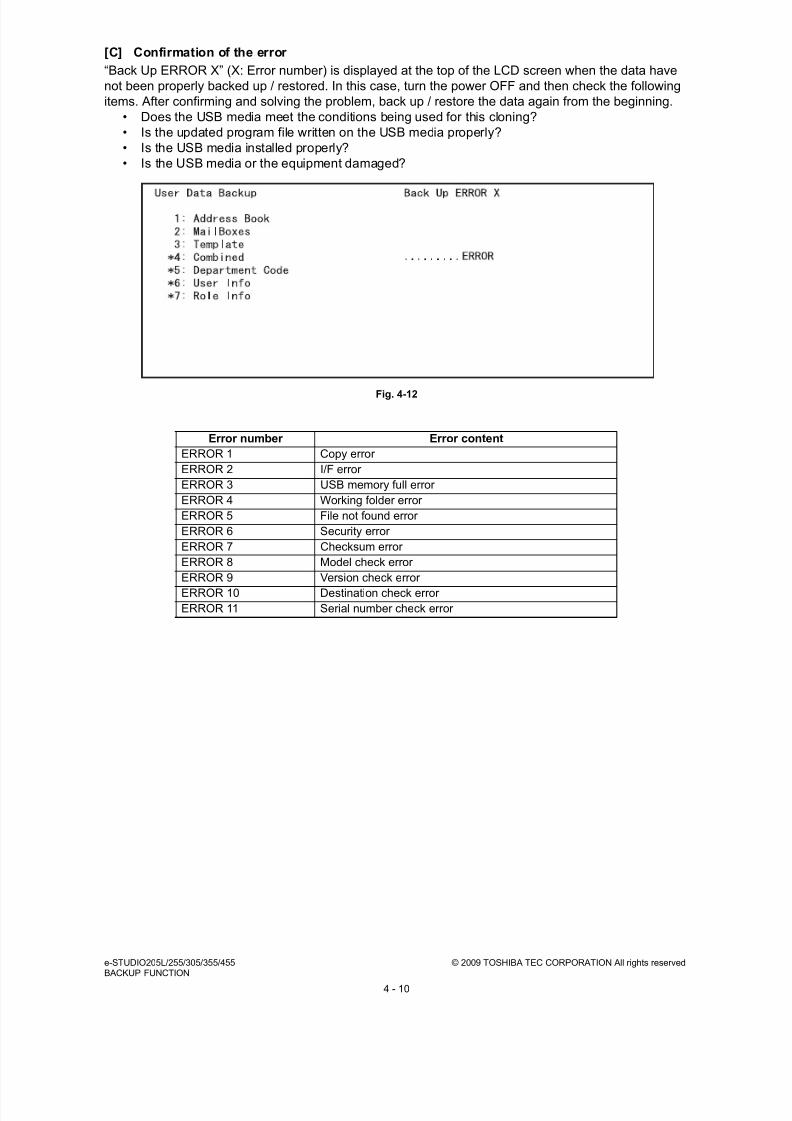
8/9/2019 Service manual E-studio 455
http://slidepdf.com/reader/full/service-manual-e-studio-455 346/670
e-STUDIO205L/255/305/355/455 © 2009 TOSHIBA TEC CORPORATION All rights reservedBACKUP FUNCTION
4 - 10
[C] Confirmation of the error
“Back Up ERROR X” (X: Error number) is displayed at the top of the LCD screen when the data have
not been properly backed up / restored. In this case, turn the power OFF and then check the following
items. After confirming and solving the problem, back up / restore the data again from the beginning.
• Does the USB media meet the conditions being used for this cloning?
• Is the updated program file written on the USB media properly?
• Is the USB media installed properly?
• Is the USB media or the equipment damaged?
Fig. 4-12
Error number Error content
ERROR 1 Copy error
ERROR 2 I/F error
ERROR 3 USB memory full error
ERROR 4 Working folder error
ERROR 5 File not found error
ERROR 6 Security error
ERROR 7 Checksum error
ERROR 8 Model check error
ERROR 9 Version check error ERROR 10 Destination check error
ERROR 11 Serial number check error

8/9/2019 Service manual E-studio 455
http://slidepdf.com/reader/full/service-manual-e-studio-455 347/670
© 2009 TOSHIBA TEC CORPORATION All rights reserved e-STUDIO205L/255/305/355/455BACKUP FUNCTION
4 - 11
4.2 AES Data Encryption Function Setting
4.2.1 General description
Data encryption is a function that encrypts data in the HDD to enhance the security.
Note that this function may affect the equipment performance.
4.2.2 Precautions
When the data encryption function is set enabled, data currently stored in the HDD will not be retrieved.Therefore when data encryption function needs to be enabled after the installation of the equipment, it
is necessary to back up the data in the HDD before setting this function and then recover them after the
setting.
• To ensure security, ask the user (machine administrator) to back up or restore the user’s data
and information in the HDD. A service technician can back up or restore them only when the
user (machine administrator) permits it.
• Some data in the HDD cannot be backed up and can be left only on printouts.
4.2.3 Setting procedure
A procedure for setting the data encryption function is shown below.
Fig. 4-13
Start
[A] Back up data in HDD
[B] Print out "FUNCTION LIST FOR MAINTENANCE"
[C] Print out "FUNCTION" list
[D] Erase HDD
[E] Replace/Format HDD
[F] Reset user's setting item and restore data/information
[G] Reset "FUNCTION LIST FOR MAINTENANCE"
[H] Reset "FUNCTION" list
[I] Check actuation of data encryption function setting
Setting completed

8/9/2019 Service manual E-studio 455
http://slidepdf.com/reader/full/service-manual-e-studio-455 348/670
e-STUDIO205L/255/305/355/455 © 2009 TOSHIBA TEC CORPORATION All rights reservedBACKUP FUNCTION
4 - 12
[A] Back up in HDD
Ask the user (machine administrator) to back up the data in the HDD. Refer to the table below for the
type of data, availability and method of backup.
[B] Print out “FUNCTION LIST FOR MAINTENANCE”
(1) Press the [USER FUNCTIONS] button and then the [USER] tab.
(2) Press the [LIST] button.
(3) Key in [*] [#] [*] [*] [3] [3] and then press the [START] button. The “FUNCTION LIST FOR
MAINTENANCE” is printed out.
Type of data in HDD Availability Backup method
Image data in the e-Filing Available
Archive them in the “e-Filing” ofTopAccess. As for the backup inBox data, all data (selectable by thebox) can be backed up / restored inone go by using “e-Filing Backup/Restore Utility”.
F-code information, Templateregistration information, Addressbook data
AvailableBack them up in the “Administrator”menu of TopAccess.
Department management data AvailableExport them in “Administrator”menu of TopAccess.
Log data (Print, Scan, FAX(Transmission/Reception)
AvailableExport them in the “Administrator”menu of TopAccess. (Import cannotbe performed.)
Data in the shared folder (Scanneddata, Saved data of copy / FAXtransmission)
Available
Copy them to the client computervia the network. (The data whichhave been copied tothe client computer cannot becopied to the shared folder.)
Role information Available
Export role information on theTopAccess menus.[User Management] tab > [User Confirm/Create/Modify] >[Role Information]
Print waiting data (Copying data andFAX reception data that are waiting tobe printed due to the paper run-outand jam, etc.)
Not availableFinish printing them after the papersupply and the jam release, etc.(The data cannot be kept.)
Print job (Private print data, Scheduleprint data)
Not availableIf any jobs are left, print them. (Thedata cannot be backed up.)
FAX saved data (Confidential /Bulletin board data)
Not availablePrint them. (The data cannot bebacked up.)
Registration data for FAXtransmission (Delayed transmission /Recovery transmission)
Not available Print them. (The data cannot bebacked up.)

8/9/2019 Service manual E-studio 455
http://slidepdf.com/reader/full/service-manual-e-studio-455 349/670
© 2009 TOSHIBA TEC CORPORATION All rights reserved e-STUDIO205L/255/305/355/455BACKUP FUNCTION
4 - 13
[C] Print out “FUNCTION” list
(1) Press the [USER FUNCTIONS] button.
(2) Press the [ADMIN] button, enter the password, and then press the [ENTER] button.
(3) Press the [LIST/REPORT] button and then the [LIST] button.
(4) Press the [FUNCTION] button. The “FUNCTION” list is printed out.
Note:Explain the procedure to the user (machine administrator) and ask him/her to enter his/her
password.
[D] Enable data encryption function
Perform the setting of the data encryption function in the code 08-9379. The setting values are shown
below.
0: Encryption disabled
1: Encryption enabled (Security priority)
2: Encryption enabled (Performance priority)
Security priority: All user data are encrypted.
Performance priority: Encryption data are generated only in a copying or a printing process temporarily.
All user data except files which are deleted in a corresponding process are encrypted.
[E] Format HDD
Perform the code 08-690:2 to format the HDD.
When the FAX Unit (GD-1250) is installed, perform “Fax Set Up (1*-100)” and “Clearing the image data
(1*-102)”. Then turn the power OFF.
1. Turn the power ON while pressing the digital keys [1] and [*] simultaneously.
2. Key in [100] and then press the [START] button.
3. Key in [102] and then press the [START] button.
4. Turn the power OFF.
[F] Reset user’s setting items and restore data/information Ask the user (machine administrator) to reset the user’s setting items and to restore data or information.
Refer to the following for the reset and restore:
* When the SSL is enabled, perform the setting of the following items again with “Create self-
certificate” of TopAccess.
Country Name
State or Province Name
Locality Name
Oranization Name
Organizational Unit Name
Common Name
Email Address
Items to reset/restore Method
Printer driver Upload them in the “Administrator” menu of TopAccess.
F-code information, Template registeringinformation, Address book data
Restore them in the “Administrator” menu of TopAccess.
Department management data Import them in the “Administrator” menu of TopAccess.
Image data in the e-Filing Restore them in the “e-Filing” of the TopAccess.
Role information Import role information on the TopAccess menus.[User Management] tab > [User Confirm/Create/Modify] > [RoleInformation]

8/9/2019 Service manual E-studio 455
http://slidepdf.com/reader/full/service-manual-e-studio-455 350/670
e-STUDIO205L/255/305/355/455 © 2009 TOSHIBA TEC CORPORATION All rights reservedBACKUP FUNCTION
4 - 14
* When wireless LAN is used, perform the setting again on the LCD panel. (only when security with a
certificate is used)
Also, upload the following certificate file with “Install Certificate for Wireless LAN” of TopAccess.
CA certificate
User certificate
[G] Reset “FUNCTION LIST FOR MAINTENANCE”
(1) Print out the "FUNCTION LIST FOR MAINTENANCE" after the HDD formatting. P.4-12 "[B] Print out “FUNCTION LIST FOR MAINTENANCE”"
(2) While pressing [1] and [3] simultaneously, turn the power ON. (Function Mode)
(3) Compare the lists which were printed before and after the formatting to check the setting items
having the different setting values. Set the value which was set before the formatting.
(4) Turn the power OFF.
[H] Reset “FUNCTION” list
Reset the initial setting of the fax function by referring to the "function list" which has been printed outfollowing the procedure below.
P.4-13 "[C] Print out “FUNCTION” list"
(1) Press the [USER FUNCTIONS] button.
(2) Press the [ADMIN] button, enter the password, and then press the [ENTER] button.
(3) Press the [FAX] button and then the [TERMINAL ID] button to set each item.
(4) Press the [INITIAL SETUP] button to set each item.
Note:
Explain to the user (machine administrator) about the next operation and ask him/her to enterhis/her password.

8/9/2019 Service manual E-studio 455
http://slidepdf.com/reader/full/service-manual-e-studio-455 351/670
© 2009 TOSHIBA TEC CORPORATION All rights reserved e-STUDIO205L/255/305/355/455BACKUP FUNCTION
4 - 15
[I] Check actuation of data encryption function setting
Check if the data encryption function is in operation.
• Press the [COUNTER] button on the control panel. If a key-shaped icon is displayed at the top right
of the screen, the data encryption function is in operation.
4.2.4 Procedure for disabling data encryption function
The basic setting procedure is the same as the one for enabling this function.
Set the value of 08-9379 to "0" (Invalid) in the following procedure.
P.4-13 "[D] Enable data encryption function"
4.2.5 Procedure for discarding HDD when data encryption function isenabled
Set the data encryption function disabled following the procedure below.
P.4-15 "4.2.4 Procedure for disabling data encryption function"
Then perform 08-1426 (Forcible HDD data clearing) to completely delete the HDD data.

8/9/2019 Service manual E-studio 455
http://slidepdf.com/reader/full/service-manual-e-studio-455 352/670
e-STUDIO205L/255/305/355/455 © 2009 TOSHIBA TEC CORPORATION All rights reservedBACKUP FUNCTION
4 - 16
4.3 Assist Mode
4.3.1 Assist mode
This equipment has the Assist Mode to enable the following functions.
(1) Update Error flags clearing (“Clear update Error Flags.”)
Even if the firmware downloading has been completed normally, the Recovery Mode may
accidentally start up when the power is turned ON again. In this case, clear the update error flags
used in the download process with this function. (Normally, the flags are automatically cleared inthe download process.)
Also in the case the Recovery Mode accidentally starts up after the replacement of SRAM on the
SYS board, the flags are cleared with this function.
(2) Data storage partition formatting (“Format Loader Partition.”)
When a defection occurs on the UI data, etc. which are stored in the HDD, the partition with the
stored UI data, etc. is formatted with this function. (Do not use this function since it is not
normally necessary.)
(3) HDD partition creation (“All Partition Delete and Create Loader Partition.”)
When the HDD is replaced or UI data, etc. are downloaded using the USB storage, it is
necessary to format a partition in the HDD before downloading. In this case, the partition iscreated in the HDD with this function.
Notes:1. When downloading with a download jig, it is not necessary to format a partition in advance.
2. Perform the HDD partition formatting only when a new HDD is installed since all data in the
current HDD are erased by this operation.
(4) SRAM data format
When SRAM board is replaced with a new one on the SYS board, abnormal values may be
written in the new SRAM. In such cases, SRAM data must be formatted with this function.
Notes:1. This function is required only when a new SRAM board is installed.
2. Do not perform this function in cases other than the installation of a new SRAM boardbecause all data in the SRAM will be deleted as a result.

8/9/2019 Service manual E-studio 455
http://slidepdf.com/reader/full/service-manual-e-studio-455 353/670
© 2009 TOSHIBA TEC CORPORATION All rights reserved e-STUDIO205L/255/305/355/455BACKUP FUNCTION
4 - 17
4.3.2 Operating procedure of assist mode
(1) Turn ON the power while [3] button and [CLEAR] button are pressed simultaneously.
• The following screen is displayed.
Fig. 4-14
(2) Select the item with the digital keys and press the [START] button.
Note:Explain the user (machine administrator) about the next operation and ask him/her to enter his/
her password.

8/9/2019 Service manual E-studio 455
http://slidepdf.com/reader/full/service-manual-e-studio-455 354/670
e-STUDIO205L/255/305/355/455 © 2009 TOSHIBA TEC CORPORATION All rights reservedBACKUP FUNCTION
4 - 18

8/9/2019 Service manual E-studio 455
http://slidepdf.com/reader/full/service-manual-e-studio-455 355/670
© 2009 TOSHIBA TEC CORPORATION All rights reserved e-STUDIO205L/255/305/355/455PREVENTIVE MAINTENANCE (PM)
5 - 1
5. PREVENTIVE MAINTENANCE (PM)
5.1 General Description
The purpose of preventive maintenance (PM) is to maintain the quality level of this equipment by
periodically inspecting and cleaning this equipment and also replacing the parts whose replacement
timing has come according to the maintenance contract. There are PM kits packaged for each unit or a
group of parts with the same replacement number of output pages, allowing you to carry out efficient
parts replacement. Also to maintain the quality level of the equipment, overhauling is required when a specified number of
pages has been printed or when a specified period of time has passed, regardless of the number of
output pages.
5.2 PM Display
5.2.1 General description
The maintenance times of the PM parts vary depending on the state of the parts, for example, if one
part is replaced due to a problem during the operation, the maintenance time of another part will
change accordingly. In this equipment, the optimal maintenance time corresponding to each part is
displayed on the control panel LCD.
The [process unit (K)] explained below is a photoconductive drum or a cleaner unit which includes a
photoconductive drum. The [developer material (K)] explained below is a developer material or a
developer unit which includes a developer material. The [PM part other than the process unit] explained
below is a fuser roller or a fuser unit which includes a fuser roller.
5.2.2 PM display conditions
The conditions of the PM display consist of the codes of the setting mode (08) for “the setting value
treated as a threshold of the PM display”, “the counter indicating the current number of prints and
driving time” and “the setting value which determines the display conditions”.
The PM timing is displayed when the counter exceeds the setting value according to the display
condition based on “the setting value which determines the display conditions”.
• Setting value treated as a threshold of the PM display
Note:When “0” is entered as the setting value, PM timing is not displayed.
08-251 : Setting value of PM counter [process unit (K)]
08-375 : Setting value of PM time counter [process unit (K)]
08-5554 : Setting value of PM counter [developer material (K)]
08-5555 : Setting value of PM time counter [developer material (K)]
08-5562 : Setting value of PM counter [parts other than the PM parts of the process unit]
08-5563 : Setting value of PM time counter [parts other than the PM parts of the process unit]

8/9/2019 Service manual E-studio 455
http://slidepdf.com/reader/full/service-manual-e-studio-455 356/670
e-STUDIO205L/255/305/355/455 © 2009 TOSHIBA TEC CORPORATION All rights reservedPREVENTIVE MAINTENANCE (PM)
5 - 2
• Counter indicating the current number of prints and driving time
08-252 : Current value of PM counter [process unit (K)]
08-376 : Current value of PM time counter [process unit (K)]
08-5568 : Current value of PM counter [developer material (K)]
08-5569 : Current value of PM time counter [developer material (K)]
08-5576 : Current value of PM counter [parts other than the PM parts of the process unit]
08-5577 : Current value of PM time counter [parts other than the PM parts of the process unit]
• Setting value which determines the display conditions
08-223 : Switching of output pages/driving counts at PM [process unit (K)]08-5581 : Switching of output pages/driving counts at PM [developer material (K)]
08-5585 : Switching of output pages/driving counts at PM [parts other than the PM parts of the
process unit]
For example, you can set the conditions of the PM display of the [process unit (K)] as follows.
If the value of 08-9891 (Warning message on the touch panel when PM time has come) is set to "0: No
warning notification", the PM display is not performed regardless of the settings above. (Default value is
"1: Display warning notification")
PM display by specifying the
number of prints
1. Key in "0" for 08-223 (Switching of output pages/driving
counts at PM [process unit (K)]).
2. Key in the value of the number of prints for the PM display
other than "0" for 08-251 (Setting value of PM counter[process unit (K)]).
PM display by specifying the
driving time
1. Key in "1" for 08-223 (Switching of output pages/driving
counts at PM [process unit (K)]).
2. Key in the value of the driving time for the PM display other
than "0" for 08-375 (Setting value of PM time counter [process
unit (K)]).
PM display by the earlier one:
when the number of prints or the
driving time reaches the set value
1. Key in "2" for 08-223 (Switching of output pages/driving
counts at PM [process unit (K)]).
2. Key in the value of the number of sheets for the PM display
other than "0" for 08-251 (Setting value of PM counter[process unit (K)]).
3. Key in the value of the driving time other than "0" for 08-375
(Setting value of PM time counter [process unit (K)]).

8/9/2019 Service manual E-studio 455
http://slidepdf.com/reader/full/service-manual-e-studio-455 357/670
© 2009 TOSHIBA TEC CORPORATION All rights reserved e-STUDIO205L/255/305/355/455PREVENTIVE MAINTENANCE (PM)
5 - 3
5.2.3 PM display contents
When the counter value exceeds the setting value, the equipment notifies you of when the
maintenance time has come by displaying the message “Time for periodic maintenance ****” on the
control panel LCD. “****” in the message is a 4-digit hexadecimal number code. This number is
allocated in the following manner, therefore the parts needing maintenance can be identified.
PM parts of the process unit (K) : 0008
PM parts of the developer material (K) : 0080
Parts other than the PM parts of the process unit : 0100
If multiple parts have reached the maintenance time, the sum of the corresponding code values listed
above is displayed in hexadecimal numbers.
For example, if the peripheral parts of the process units (K) and developer material (K) reach the
maintenance time, the 4-digit hexadecimal number code will be “0188” in hexadecimal numbers:
0008+0080+0100=0188.

8/9/2019 Service manual E-studio 455
http://slidepdf.com/reader/full/service-manual-e-studio-455 358/670
e-STUDIO205L/255/305/355/455 © 2009 TOSHIBA TEC CORPORATION All rights reservedPREVENTIVE MAINTENANCE (PM)
5 - 4
5.2.4 Clearing counter
The counter indicating “current number of prints and driving time” used for the PM display function is
reset by entering “0” in it or clearing it in the PM support mode.
Note:Even if “0” is entered in the PM management setting value of the setting mode (08), the
corresponding counter for the PM display is not reset. Be sure to clear the counter in the PM
support mode when the maintenance is finished.
The reset condition of each counter is as follows:
• 08-252: Current value of PM counter [process unit (K)]
• 08-376: Current value of PM time counter [process unit (K)]
When the current value of “CLEANER/DRUM” on the main screen or “DRUM” on the sub-screen in
the PM support mode is cleared, the counter is reset.
• 08-5568: Current value of PM time counter [developer material (K)]
• 08-5569: Current value of PM time counter [developer material (K)]
When the current value of “DEVELOPER” on the main screen or “DEVELOPER” on the sub-screen
in the PM support mode is cleared, the counter is reset.
• 08-5576: Current value of PM counter [parts other than the PM parts of the process unit]
• 08-5577: Current value of PM time counter [parts other than the PM parts of the process unit]When the current value of “FUSER” on the main screen or “FUSER ROLLER” on the sub screen in
the PM support mode is cleared, the counter is reset.
Note:The following counters are cleared by executing the EPU replacement mode.
08-252: Current value of PM counter [process unit (K)]
08-376: Current value of PM time counter [process unit (K)]
08-5568: Current value of PM counter [developer material (K)]
08-5569: Current value of PM time counter [developer material (K)]

8/9/2019 Service manual E-studio 455
http://slidepdf.com/reader/full/service-manual-e-studio-455 359/670
© 2009 TOSHIBA TEC CORPORATION All rights reserved e-STUDIO205L/255/305/355/455PREVENTIVE MAINTENANCE (PM)
5 - 5
5.3 General Descriptions for PM ProcedurePerform the preventive maintenance in the following timing.
• e-STUDIO205L: every 80,000 sheets
• e-STUDIO255: every 10,000 sheets
• e-STUDIO305: every 120,000 sheets
• e-STUDIO355: every 125,000 sheets
• e-STUDIO455: every 150,000 sheets
(1) Preparation• Ask the user about the current conditions of the equipment and note them down.
• Before starting maintenance, make some sample copies and store them.
• See the replacement record and check the parts to be replaced in the PM support mode (6S-
2) or list printing mode (9S-103).
6S-2 : [6] + [START] + [POWER] ON [2] [START]
9S-103 : [9] + [START] + [POWER] ON [103] [START]
Fig. 5-1
• Turn OFF the power and make sure to unplug the equipment.
(2) Perform a preventive maintenance using the following checklist and illustrations. Refer to the
Service Manual if necessary.
(3) Plug in the equipment after the maintenance has been finished. Then turn ON the power and
make some copies to confirm that the equipment is working properly.
PM SUPPORT CODE LIST
MM-DD-YY 09:30
UNIT OUTPUT PAGES PM OUTPUT PAGE DRIVE COUNTS PM DRIVE COUNTS
DRUM 81813 150000 119758 220000DRUM BLADE 81813 150000 119758 220000GRID 81813 150000 119758 220000MAIN CHARGER WIRE 81813 150000 119758 220000SEPARATION FINGER (DRUM) 81813 150000 119758 220000

8/9/2019 Service manual E-studio 455
http://slidepdf.com/reader/full/service-manual-e-studio-455 360/670
e-STUDIO205L/255/305/355/455 © 2009 TOSHIBA TEC CORPORATION All rights reservedPREVENTIVE MAINTENANCE (PM)
5 - 6
5.4 PM Support Mode
5.4.1 General description
The timing for the parts replacement usually depends on the number of output pages ever printed after
they were replaced before. However, the life span of them changes depending on the general use of
users and the environment in which the equipment is placed. Therefore, it is necessary to consider not
only the number of output pages but also the drive counts when deciding the timing for the parts
replacement in order to utilize the parts and materials effectively.
This equipment has the PM support mode, which makes it possible to see the general use of each part
(the number of output pages, drive counts) and replacement record and to do a counter clearing
operation more efficiently when replacing.
The replacement record can be printed out in the list printing mode (9S-103).
5.4.2 Operational flow and operational screen
[ 1 ] Operational flow
Fig. 5-2
* The screen goes back to the main screen when the counter clear is executed or the [CANCEL]
button is pressed after moving from the main screen, while it goes back to the sub screen aftermoving from the sub screen.
[RETURN] pressed
[RETURN] pressed
[CANCEL] pressed
[CANCEL] pressed
Clear finished
Clear finished
[2] [START]
Adjustment finished
[1] [START]
Main unit chosen[SUB UNIT] pressed
Main unit chosen[RESET]
Sub unit chosen[RESET] pressed
PM support mode activated
[6]+[START]+[POWER]ON
Auto-toner automatic
adjustment performed
( Chapter 3.1)
Main screen
Main unit list displayed
Sub screen
Sub unit list displayed
Clear screen
Counter clearconfirmation displayed
Counter clear performed
[INITIALIZE]pressed

8/9/2019 Service manual E-studio 455
http://slidepdf.com/reader/full/service-manual-e-studio-455 361/670
© 2009 TOSHIBA TEC CORPORATION All rights reserved e-STUDIO205L/255/305/355/455PREVENTIVE MAINTENANCE (PM)
5 - 7
[ 2 ] Operational screen
1. Main screen
Fig. 5-3
Displaying of the main unit name
Back to the PM support mode activation screenClearing of the chosen unit counters (all the sub unit (parts) counters belonging to that unit)
All counters are cleared when the unit is not selected
Moving to the sub screen
Moving to the next/previous page
Displaying of the standard number of output pages counts (x 1,000) to replace the unit parts
Displaying of the present drive counts (x 1,000)
“*” is displayed next to the present number when the number of drive counts has exceeded its
PM standard number.
Displaying of the standard number of drive counts (x 1,000) to replace the unit parts
Displaying of the present number of output pages counts (x 1,000)
When there are differences among the sub units (parts), “_” is displayed and “CHECKSUBUNIT” is displayed at the top
“*” is displayed next to the present number when the number of output pages counts has
exceeded its PM standard number.
Displaying of the number of output pages counts (Cpy.), drive counts (Cnt.) and previous
replacement date (Chg.) for a chosen unit.
When the replacement date for the sub unit is different, press the [SUB UNIT] button to move
to the sub screen and see each information, otherwise information is not displayed
10
9
1
2 3 4 5
6 7 8
1
2
3
4
5
6
7
8
9
10

8/9/2019 Service manual E-studio 455
http://slidepdf.com/reader/full/service-manual-e-studio-455 362/670
e-STUDIO205L/255/305/355/455 © 2009 TOSHIBA TEC CORPORATION All rights reservedPREVENTIVE MAINTENANCE (PM)
5 - 8
Notes:• “—” is always displayed at the drive counts section for the reversing automatic document
feeder (RADF) and feed unit.
• The paper source differs depending on the structure of options, however, “0.0k” is displayed
in “OUTPUT PAGES (k)” and its standard number of output pages is displayed in “PM
OUTPUT PAGES (k)” even for the installed paper source.
2. Sub screen
Fig. 5-4
Displaying of the sub unit (parts) name
Back to the main screen
Clearing of the chosen sub unit (parts) counters
Displaying of the present number of output pages counts (x 1,000)
“*” is displayed next to the present number when the number of output pages counts has
exceeded its PM standard number.
Displaying of the standard number of output pages counts (x 1,000) to replace the sub unit
(parts)
Displaying of the present drive counts (x 1,000)
“*” is displayed next to the present number when the number of drive counts has exceeded its
PM standard number.
Displaying of the standard number of drive counts (x 1,000) to replace the sub unit (parts)
Displaying of the number of output pages counts, drive counts and previous replacement date
for a chosen sub unit
8
1
2 3
4 5 6 7
1
2
3
4
5
6
7
8

8/9/2019 Service manual E-studio 455
http://slidepdf.com/reader/full/service-manual-e-studio-455 363/670
© 2009 TOSHIBA TEC CORPORATION All rights reserved e-STUDIO205L/255/305/355/455PREVENTIVE MAINTENANCE (PM)
5 - 9
3. Clear screen
Fig. 5-5
When the [INITIALIZE] button is pressed, “Present number of output pages counts” and
“Present driving counts” are cleared and “Previous replacement date” is updated.
1
1

8/9/2019 Service manual E-studio 455
http://slidepdf.com/reader/full/service-manual-e-studio-455 364/670
e-STUDIO205L/255/305/355/455 © 2009 TOSHIBA TEC CORPORATION All rights reservedPREVENTIVE MAINTENANCE (PM)
5 - 10
[ 3 ] LCD screen display list
Note:The name inside [ ] is displayed on the LCD screen.
Main screen Sub-screen
Drum/cleaner unit [CLEANER/DRUM] Drum [DRUM]Drum cleaning blade [DRUM BLADE]Main charger grid [GRID]Needle electrode [NEEDLE ELECTRODE]Separation finger for drum [SEPARATION FINGER (DRUM)]Recovery blade [RECOVERY BLADE]
Developer unit [DEVELOPER] Developer [DEVELOPER]
Transfer unit [TRANSFER UNIT] TRANSFER ROLLER [Transfer Roller]
Filter [FILTER] Ozone filter [OZONE FILTER]
Fuser unit [FUSER] Fuser roller [FUSER ROLLER]Pressure roller [PRESS ROLLER]Separation finger for fuser roller [SEPARATION FINGER (FUSER)]
Upper drawer [1st CST.] Pickup roller [PICK UP ROLLER (1st CST.)]Feed roller [FEED ROLLER (1st CST.)]Separation roller [SEP ROLLER (1st CST.)]
Lower drawer [2nd CST.] Pickup roller [PICK UP ROLLER (2nd CST.)]Feed roller [FEED ROLLER (2nd CST.)]Separation roller [SEP ROLLER (2nd CST.)]
Bypass unit [SFB] Feed roller [FEED ROLLER (SFB)]Separation pad [SEP PAD (SFB)]
RADF [RADF] Pickup roller [PICK UP ROLLER (RADF)]Feed roller [FEED ROLLER (RADF)]Separation roller [SEP ROLLER (RADF)]
LCF [LCF] Pickup roller [PICK UP ROLLER (LCF)]Feed roller [FEED ROLLER (LCF)]Separation roller [SEP ROLLER (LCF)]
PFP upper drawer [3rd CST.] Pickup roller [PICK UP ROLLER (3rd CST.)]]Feed roller [FEED ROLLER (3rd CST.)]Separation roller [SEP ROLLER (3rd CST.)]
PFP lower drawer [4th CST.] Pickup roller [PICK UP ROLLER (4th CST.)]Feed roller [FEED ROLLER (4th CST.)]Separation roller [SEP ROLLER (4th CST.)]

8/9/2019 Service manual E-studio 455
http://slidepdf.com/reader/full/service-manual-e-studio-455 365/670
© 2009 TOSHIBA TEC CORPORATION All rights reserved e-STUDIO205L/255/305/355/455PREVENTIVE MAINTENANCE (PM)
5 - 11
5.4.3 Work flow of parts replacement
The timing for the parts replacement usually depends on the number of output pages ever made after
they were replaced before. However, its drive counts time is also to be considered when replacing the
parts. Even if the number of output pages has reached the level of replacement, for instance, the part
may still be usable with its drive counts not reaching the specified drive counts. On the other hand, the
part may need replacement even if the number of output pages has not reached the level of
replacement with its driving time exceeding the specified drive counts. The life span of some parts such
as feed roller is heavily dependent on the number of output pages rather than the drive counts.
The following work flow diagram shows how to judge the timing of replacement with the number of
output pages and the drive counts.
Example 1:
When the number of output pages has reached the specified level
Example 2:
When the image failure occurred before the number of output pages has reached the specified
level
• The parts in RADF
• The parts in feeding system
• The parts in the drum/cleaner unit
• The parts in the fuser unit
• The parts in the developer unit
• The parts in the transfer unit
Replace the part.
Yes
No
Replace the part.
Check the drive counts at PM
support mode.
Does it exceed the specified
drive counts?
Replace the part after the
drive counts has reached the
specified count.
The part is still usable.
Check the drive counts of all parts at PM support mode.
Does it exceed the specified drive count?
Check the part and equipment according to the “TROUBLESHOOTING”.
Replace the part.

8/9/2019 Service manual E-studio 455
http://slidepdf.com/reader/full/service-manual-e-studio-455 366/670
e-STUDIO205L/255/305/355/455 © 2009 TOSHIBA TEC CORPORATION All rights reservedPREVENTIVE MAINTENANCE (PM)
5 - 12
5.5 EPU Replacement Mode
5.5.1 General description
As this equipment complies with the ERU (Easy Replacement Unit) rule, the EPUs (drum/cleaner unit,
developer unit) of this equipment can be removed or reinstalled easily.
When each EPU is replaced with a new unit at PM, the IC chip in the EPU board installed at the bottom
of the developer unit detects whether a new or an old unit is installed. When the IC chip memory judges
that the installed unit is a new one, the series of operations required at the replacement (counter reset
for supply items in the EPU, auto-toner sensor initial adjustment and automatic gamma adjustment) is
smoothly performed.
Note:If only the supply items in the EPU at PM are to be replaced, perform the life counter reset for
each supply item; if developer material is to be replaced, perform the auto-toner sensor
adjustment and the automatic gamma adjustment in the PM support mode as described in
Chapter 5.
5.5.2 Operation flow
The following is the operation flow.
Advance preparation
A4/LT size papers need to be loaded in the cassette for automatic gamma adjustment. Before
performing the EPU replacement mode, load the A4/LT size papers into the cassette, then set the
cassette paper size.

8/9/2019 Service manual E-studio 455
http://slidepdf.com/reader/full/service-manual-e-studio-455 367/670
© 2009 TOSHIBA TEC CORPORATION All rights reserved e-STUDIO205L/255/305/355/455PREVENTIVE MAINTENANCE (PM)
5 - 13
Fig. 5-6
Remove the used EPU from the
equipment. Set the developer
material in the developing part
of the new EPU. Set the EPU in
the equipment, then close the
front cover.
Starts EPU replacement
mode
Step 0
Step 1
Step 2
Step 3
Step 4
Step 5
Load A4 or LT size paper into
the cassette, set the cassette
paper size, then turn OFF the
power.
Turn ON the power while
pressing [7] and [START]
buttons.
Open the front cover, then
set the toner cartridge.
Press [OK].
Press [OK].
Place the printed gamma chart
on the original glass, then
press [OK].
Press the [ON/OFF] button
for a few seconds.
Operation flow Display transition of control panel Behavior flow of equipment
Test mode
Adjustment mode
Open the front cover and set the
toner cartridge. Close the cover.
Press [OK].
Set A4/LT paper in the drawer
and press [OK].
If it cannot be set, press
[CANCEL] to finish the
adjustment.
Place the printed chart with its
face down and the darkest area
to the left. Then close the
original cover or the ADF and
press [OK].
Test mode
Press and hold the [POWER]
button until the power is
turned OFF.
Automatic toner
adjustment
Rewrites IC chip
"New" -> "Used"
Clears counters ofconsumables in the EPU
Prints the gamma chart
Reads the gamma chart,
then performs automatic
gamma adjustment
Power off
about 2 min.

8/9/2019 Service manual E-studio 455
http://slidepdf.com/reader/full/service-manual-e-studio-455 368/670
e-STUDIO205L/255/305/355/455 © 2009 TOSHIBA TEC CORPORATION All rights reservedPREVENTIVE MAINTENANCE (PM)
5 - 14
5.5.3 Counters to be cleared
• 08-1550: Drum counter
• 08-1158: Drum cleaning blade counter
• 08-1174: Main charger grid counter
• 08-1182: Needle electrode counter
• 08-1172: Drum separation finger counter
• 08-1336: Recovery blade counter
• 08-1200: Developer material counter
• 08-252: K-PM counter current value
• 08-376: K-PM time counter current value
• 08-5568: Developer material-K PM counter current value
• 08-5569: Developer material-K PM time counter current value
5.5.4 Precautions
• When the power is turned ON in the normal mode or during warming-up in the normal mode, the
error code C3D1 appears after a new EPU unit (with new IC chip data) is installed. This indicates
that the installed EPU unit has not been set up. Turn the power OFF and then back ON while
pressing the digital key [7] and the [START] button simultaneously. Then the equipment enters
the EPU replacing mode.
• When the power is turned ON while pressing the digital key [7] and the [START] buttonsimultaneously, the error code C3D2 appears after an old EPU unit (with old IC chip data) is
installed. This is for preventing the equipment from detecting that the installed unit is a new one
and performing wrong operations such as supply item counter reset. In this case, turn the power
OFF and then back ON in the normal mode. The equipment returns to its normal operations.
• If IC chip information is not written as “used IC chip” in step 1, an error (C3D0) is displayed. If it
occurs, perform the maintenance of each part according to the Troubleshooting.
• If you press [CANCEL] in step 3, the EPU replacement mode ends without automatic gamma
adjustment being performed.
• If [Adjustment error Press [OK] to perform the adjustment again or [CANCEL] to finish it.] isdisplayed in step 4, this means that the automatic gamma adjustment has failed. Check that the
original is placed on the original glass in the correct direction, and press [OK] to start the
adjustment again. If you press [CANCEL], the adjustment is cancelled and the EPU replacement
mode ends.
• If automatic gamma adjustment is not performed in the EPU replacement mode, the default
gamma slope angle is used. To obtain optimal image quality, perform the adjustment according to
the procedure in the “Automatic gamma adjustment” in the chapter of "Image Quality
Adjustment."
• If the EPU replacement mode does not function, check that the value of 08-4556 (Detection
setting of new or old EPU) is set to "1: Enabled.” If this value is set to "0: Disabled", the EPU
replacement mode does not function.

8/9/2019 Service manual E-studio 455
http://slidepdf.com/reader/full/service-manual-e-studio-455 369/670
© 2009 TOSHIBA TEC CORPORATION All rights reserved e-STUDIO205L/255/305/355/455PREVENTIVE MAINTENANCE (PM)
5 - 15
5.5.5 To allow the equipment to detect a recycled unit as a new one
after replacement
To recycle an old EPU after replacement and also let the equipment detect that it is a new one, the
supply items in the EPU and the IC chip data in the EPU board must be replaced.
In this case, the EPU board itself must be replaced with a new one (service part) or the IC chip data
must be overwritten using a jig.
If the EPUs are replaced in the PM support mode instead of the EPU replacing mode noted in this
chapter, the replacement of the EPU board and the overwriting of the IC chip data are not necessary.
Information in the IC chip can be confirmed with 08-4555 (Information check of new or old EPUmemory). The display of [0xff00(NEW)] indicates a new IC chip while [0x00ff(OLD)] indicates a used
one. A hexadecimal value ending with "-" indicates that invalid data have been entered. In this case,
rewriting with a jig is required.

8/9/2019 Service manual E-studio 455
http://slidepdf.com/reader/full/service-manual-e-studio-455 370/670
e-STUDIO205L/255/305/355/455 © 2009 TOSHIBA TEC CORPORATION All rights reservedPREVENTIVE MAINTENANCE (PM)
5 - 16
5.6 Fuser Unit Status Detection Mode
5.6.1 General description
As this equipment complies with the ERU provisions (Easy Replacement Unit), the fuser unit can be
removed or reinstalled without any problem.
The fuse (service part) for detection of a new fuser unit can be installed in the unit. The circuit
determining the fuser unit status judges whether the fuser unit is new or used by detecting the status of
the fuse. In addition, when the circuit detects that a new fuser unit is connected, it supplies current to
blow out the fuse to clear the fuser-related life counters.
Note:If only the supply parts in the fuser unit are to be replaced at PM, perform life counter clearing for
each one in the PM support mode as described in this chapter.
5.6.2 Operational flow
(1) When replacing supply parts or the fuser unit at PM, install a new fuse in it.
Note:If a fuser unit with an installed fuse is selected, replace that the fuse with a new one because it
will have been blown out.
(2) Install the fuser unit in the equipment.
(3) Turn the power ON. If the fuser unit is then judged determined to be new, the fuser-related life
counters are automatically cleared.
5.6.3 Counters to be cleared
• 08-1246: Fuser roller counter
• 08-1250: Pressure roller counter
• 08-1268: Fuser roller separation finger counter
• 08-1372: Heater and energizing time accumulating counter
• 08-1378: Counter for period of time fuser unit is at ready temperature
• 08-1380: Counter for period of time fuser unit is at printing temperature
• 08-1382: Counter for period of time fuser unit is at energy saving temperature• 08-1385: Number of output pages (Thick paper 1)
• 08-1386: Number of output pages (Thick paper 2)
• 08-1387: Number of output pages (Thick paper 3)
• 08-1388: Number of output pages (OHP film)
• 08-1411: Counter for envelopes
• 08-1412: Counter for tab paper
5.6.4 Precautions
• When the counters are not cleared, though the fuser unit is new, check that the value of the code
08-4549 is set at "0". If the value is "1", change it to "0", turn the power OFF and then back ON.
Then check the counter values again.08-4549 (Detection setting of new or old fuser unit) 0: Enabled, 1: Disabled
• When the fuse is not blown out, though the fuser unit is new, a C4C0 error occurs. In this case,
replace the fuse and turn the power OFF and then back ON, or remove the fuse and clear the
counters in the PM support mode.

8/9/2019 Service manual E-studio 455
http://slidepdf.com/reader/full/service-manual-e-studio-455 371/670
© 2009 TOSHIBA TEC CORPORATION All rights reserved e-STUDIO205L/255/305/355/455PREVENTIVE MAINTENANCE (PM)
5 - 17
5.7 Preventive Maintenance Checklist
The following is the check items of each unit at preventive maintenance.
Symbols/Values used in the checklist
Notes:• Perform cleaning and lubricating in the following timing. Lubricate the replacement parts
according to the replacement cycle.
- e-STUDIO205L: every 80,000 sheets
- e-STUDIO255: every 100,000 sheets
- e-STUDIO305: every 120,000 sheets
- e-STUDIO355: every 125,000 sheets
- e-STUDIO455: every 150,000 sheets
• Values under “Replacement” indicate the replacement cycle for the e-STUDIO205L/255/305/
355/455.
• The replacement cycle of the parts in the feeding section equals to the number of sheets fed
from each paper source.
• Be careful not to put oil on the rollers, belts and belt pulleys when lubricating.
Cleaning Lubrication/Coating Replacement Operation check
A: Clean with alcoholB: Clean with soft pad,
cloth or vacuum
cleaner
L: Launa 40SI: Silicon oilW1: White grease (Molykote EM-
30L)W2: White grease (Molykote HP-
300) AV: Alvania No.2FL: Floil (GE-334C)CG: Conductive grease (KS-660)
Value: Replacementcycle
R: Replace if
deformed ordamaged
After cleaning or
replacement, confirmthere is no problem.

8/9/2019 Service manual E-studio 455
http://slidepdf.com/reader/full/service-manual-e-studio-455 372/670
e-STUDIO205L/255/305/355/455 © 2009 TOSHIBA TEC CORPORATION All rights reservedPREVENTIVE MAINTENANCE (PM)
5 - 18
5.7.1 Scanner
Fig. 5-7
* a, b. Original glass/ADF original glass
Clean both sides of the original glass and ADF original glass.
Note:Make sure that there is no fingerprints or oil staining on part of the original glass on where the
original scale is mounted since the shading correction plate is located below the scale to be
scanned.
Items to check Cleaning LubricationReplacement
(x 1,000 sheets)
Operation
check
Parts list
<P-I>
a Original glass A or B 22-3
b ADF original glass B 22-1
c Mirror 1 B
d Mirror 2 B
e Mirror 3 B
f Reflector B 23-5
g Lens B 12-13
h Exposure lamp R 23-3
i Automatic originaldetection sensor
B 12-16
j Slide sheet
(front and rear)
A or B R 15-1
d e
b a f h c g j

8/9/2019 Service manual E-studio 455
http://slidepdf.com/reader/full/service-manual-e-studio-455 373/670
© 2009 TOSHIBA TEC CORPORATION All rights reserved e-STUDIO205L/255/305/355/455PREVENTIVE MAINTENANCE (PM)
5 - 19
5.7.2 Laser optical unit
Fig. 5-8
Items to check Cleaning LubricationReplacement
(x 1,000 sheets)
Operation
check
Parts list
<P-I>a Slit glass B
a

8/9/2019 Service manual E-studio 455
http://slidepdf.com/reader/full/service-manual-e-studio-455 374/670
e-STUDIO205L/255/305/355/455 © 2009 TOSHIBA TEC CORPORATION All rights reservedPREVENTIVE MAINTENANCE (PM)
5 - 20
5.7.3 Paper feeding section
Fig. 5-9
* c. Separation roller
Apply an even coat of grease (Alvania No.2) to all round the inside of the spring.
When replacing the separation roller, apply adequate amount of white grease (Molykote HP-300)
on the places of the holder shown in the figure (4 places).
Items to check Cleaning LubricationReplacement
(x 1,000 sheets)
Operation
check
Parts list
<P-I>
a Pickup roller 80/80/80/80/80 17-20
b Feed roller 80/80/80/80/80 17-27
c Separation roller AV, W2 80/80/80/80/80 17-6
d Transport roller (1st/2nd)
A R 18-318-18
e Registration roller A R 13-1721-1
f Bypass Feed roller 80/80/80/80/80 20-5
g Bypass Separation pad AV, W2 80/80/80/80/80 20-4
h Bypass tray B
i Paper guide B
j Drive gear(tooth face and shaft)
W1
k Plastic bushing bearing W1
l Bypass drive gear (shaft)
W1
m Bypass GCB bushingbearing
L 20-8
b
a
f
e
c
b
c
g
d
h
k
l, m

8/9/2019 Service manual E-studio 455
http://slidepdf.com/reader/full/service-manual-e-studio-455 375/670
© 2009 TOSHIBA TEC CORPORATION All rights reserved e-STUDIO205L/255/305/355/455PREVENTIVE MAINTENANCE (PM)
5 - 21
Note:Make sure that the grease does not adhere to the roller surface. Wipe it off with alcohol if
adhered.
* j, l. Drive gears in the paper feeding section (teeth of gears and shafts)
Apply some white grease (Molykote EM-30L) to the teeth of gears and shafts of the drive gears.
Note:
Make sure that oil is not running over or scattered around as the gear is rotated coming into theclutch after applying Molykote to the gear which is located near the clutch. The quantity of
Molykote should be smaller than that to be applied to the other parts.
Fig. 5-10
Fig. 5-11
Apply grease on the inner surface
Apply white grease

8/9/2019 Service manual E-studio 455
http://slidepdf.com/reader/full/service-manual-e-studio-455 376/670
e-STUDIO205L/255/305/355/455 © 2009 TOSHIBA TEC CORPORATION All rights reservedPREVENTIVE MAINTENANCE (PM)
5 - 22
5.7.4 Drum related section
Fig. 5-12
Items to check Cleaning LubricationReplacement
(x 1,000 sheets)
Operation
check
Parts list
<P-I>
a Photoconductive drum 80/100/120/125/150
b Discharge LED B
c Whole cleaner unit B
d Drum cleaning blade 80/100/120/125/
150
27-8
e Separation finger fordrum
80/100/120/125/150
27-12
f Recovery blade B 80/100/120/125/150
27-10
g Ozone filter 240/200/240/250/300
13-14
h Transfer roller 80/100/120/125/150
26-5
i Separation needle B R 26-11
j Transfer guide B
k Separation cover B 26-12
l Transfer roller guide roller B 26-8
m Main charger case B
n Needle electrode 80/100/120/125/150
25-6
o Main charger wirecleaner
R 27-8
p Main charger grid 80/100/120/125/150
25-11
d f b
g
j
e
a
h, l, r
i
m cn po
k
q
s

8/9/2019 Service manual E-studio 455
http://slidepdf.com/reader/full/service-manual-e-studio-455 377/670
© 2009 TOSHIBA TEC CORPORATION All rights reserved e-STUDIO205L/255/305/355/455PREVENTIVE MAINTENANCE (PM)
5 - 23
* d. Drum cleaning blade
Since the edge of the blade is vulnerable and can be easily damaged by factors such as the
adherence of paper dust. Replace the cleaning blade with new ones if poor images are printed
due to the damaged blade regardless of the number of output pages if which have been made.
* e. Separation fingers for drum
The paper jam may be caused if the tip of the separation finger is damaged or deformed. If there
is any problem with it, replace the finger with a new one regardless of the number of output
pages which have been made.
If any mark which was made by the finger appears on the printed image, clean the tip of the
finger.
Notes:• Wipe the tip of the finger lightly with a dry cloth trying not to deform it.
Do not leave the lint on the tip.
• Apply patting powder to the tip of the fingers and drum surface after replacing or cleaning
them to reduce the load on the drum surface by the finger.
* f. Recovery blade
Replace the recovery blade regardless the number of output pages if the edge of the blade get
damaged.
When cleaning the inside of the cleaner unit, be careful of the following in order not to damage
the Mylar attached on the toner recovery auger:
• Do not use an air blower for cleaning (Use a vacuum cleaner).
• When using a vacuum cleaner, be careful not to hit the nozzle of the vacuum cleaner tothe Mylar.
• When rotating the toner recovery auger, rotate it only in the same direction as that for
transporting toner.
* h. Transfer roller
If there is damage on the roller, replace it even if the replacement time has not come.
* i. Separation needle
When cleaning the separation needle, be careful not to bend the needlepoint or leave lint on the
needlepoint. If removing the dust is difficult, use brush to remove it.
* j. Transfer guideIf there is paper dust in the whole transfer unit including the transfer guide, wipe them with a dry
cloth. If the transfer guide is removed, clean the wall inside the unit.
* m, n. Main charger case/Needle electrode
Clean the main charger case with a cloth soaked in water and squeezed tightly, and then wipe
them with a dry cloth.
Clean the needle electrode only with the main charger cleaner.
Replace the needle electrode with a new one if it is damaged regardless of the number of output
pages which have been mode.
Note:
Do not touch the needle electrode with your bare hand when attaching the needle electrode.
q Front-transfer guide B
r Transfer roller gear B 26-9
s Toner cartridge drive gearshaft
W1
t Contact point of terminals B
Items to check Cleaning LubricationReplacement
(x 1,000 sheets)
Operation
check
Parts list
<P-I>

8/9/2019 Service manual E-studio 455
http://slidepdf.com/reader/full/service-manual-e-studio-455 378/670
e-STUDIO205L/255/305/355/455 © 2009 TOSHIBA TEC CORPORATION All rights reservedPREVENTIVE MAINTENANCE (PM)
5 - 24
5.7.5 Developer section
Fig. 5-13
* a. Do not use alcohol for cleaning the developer unit.
* b. Developer material
After replacing the developer material, be sure to perform the auto-toner adjustment.
P.3-2 "3.2 Adjustment of Auto-Toner Sensor"
* g. Oil seal
Mixer unit (Shafts of mixers 1, 2 and 3) 6 pcs.
During replacement, coat the oil seal with grease (Alvanian No.2).
Items to check Cleaning LubricationReplacement
(x 1,000 sheets)
Operation
check
Parts list
<P-I>
a Whole developer unit B
b Developer material 80/100/120/125/150
c Front shield B R 28-32
d Guide roller B 29-17
e Side shield B R 28-3028-31
f Developer unit lower stay B
g Oil seal (6 pcs.) AV 480/600/720/750/900
28-129-8
29-12
a
b
f
g
d
e
c

8/9/2019 Service manual E-studio 455
http://slidepdf.com/reader/full/service-manual-e-studio-455 379/670
© 2009 TOSHIBA TEC CORPORATION All rights reserved e-STUDIO205L/255/305/355/455PREVENTIVE MAINTENANCE (PM)
5 - 25
(1) Push in a new oil seal parallel to the
mounting hole section of the developer frame
or outside of the holder.
* Pay attention to the direction in which the
oil seal is attached. (See figure on right.)
(2) Apply an even coat of grease to the inside of
the oil seal.
• Amount: About two small drops
(3) Wipe off any grease the exudes from theinside.
Fig. 5-14
Outside
Inside
Developer frame(Nozzle mixer)
Grease
Oil seal

8/9/2019 Service manual E-studio 455
http://slidepdf.com/reader/full/service-manual-e-studio-455 380/670
e-STUDIO205L/255/305/355/455 © 2009 TOSHIBA TEC CORPORATION All rights reservedPREVENTIVE MAINTENANCE (PM)
5 - 26
5.7.6 Fuser unit
Fig. 5-15
* a. Fuser roller
When replacing the fuser roller, apply small amount of grease on the inside of fuser roller
bearings.
Items to check Cleaning LubricationReplacement
(x 1,000 sheets)
Operation
check
Parts list
<P-I>a Fuser roller W2 240/200/240/250/
30031-15
b Pressure roller 240/200/240/250/300
32-8
c Separation finger forfuser roller
80/100/120/125/150
31-22
d Fuser unit entrance guide A 32-11
e Thermistor (3 pcs.) A R 31-1231-13
f Drive gear (tooth face
and shaft)
W2 R 31-11
g Fuser roller gear R 31-18
c
a, g
e
b
d
f

8/9/2019 Service manual E-studio 455
http://slidepdf.com/reader/full/service-manual-e-studio-455 381/670
© 2009 TOSHIBA TEC CORPORATION All rights reserved e-STUDIO205L/255/305/355/455PREVENTIVE MAINTENANCE (PM)
5 - 27
* c. Separation fingers for fuser roller
The paper jam may be caused if the tip of the finger is damaged or deformed. If there is any
problem with it, replace the finger with a new one regardless of the number of output pages
which have been made. Do not damage the tip of the finger during the cleaning. The finger may
be damaged if the toner adhering to the tip of it is scraped off forcibly. Replace the finger if the
toner is sticking to it heavily.
* e. Thermistor
Clean the thermistor with alcohol if the toner or dirt is sticking to it when the fuser roller is
replaced.Do not deform or damage the thermistor during the cleaning. Replace the thermistor with a new
one if it is damaged or deformed regardless of degree.

8/9/2019 Service manual E-studio 455
http://slidepdf.com/reader/full/service-manual-e-studio-455 382/670
e-STUDIO205L/255/305/355/455 © 2009 TOSHIBA TEC CORPORATION All rights reservedPREVENTIVE MAINTENANCE (PM)
5 - 28
5.7.7 Paper exit section / Reverse section
Fig. 5-16
* c, d. e-STUDIO355/455 only
Items to check Cleaning LubricationReplacement
(x 1,000 sheets)
Operation
check
Parts list
<P-I>
a Exit/reverse guide A
b Exit roller A R 33-3
c Transport roller A R 34-8
d Reverse roller A R 34-15
e Drive gear SI 33-19
f Conductive bushing CG 33-6
[ e-STUDIO355/455 ][ e-STUDIO205L/255/305 ]
b
dc
e

8/9/2019 Service manual E-studio 455
http://slidepdf.com/reader/full/service-manual-e-studio-455 383/670
© 2009 TOSHIBA TEC CORPORATION All rights reserved e-STUDIO205L/255/305/355/455PREVENTIVE MAINTENANCE (PM)
5 - 29
5.7.8 Automatic duplexing unit
Fig. 5-17
Items to check Cleaning LubricationReplacement
(x 1,000 sheets)
Operation
check
Parts list
<P-I>
a Transport roller (upper and lower)
A R 35-235-3
b Drive gear W1 35-1735-18
a
b

8/9/2019 Service manual E-studio 455
http://slidepdf.com/reader/full/service-manual-e-studio-455 384/670
e-STUDIO205L/255/305/355/455 © 2009 TOSHIBA TEC CORPORATION All rights reservedPREVENTIVE MAINTENANCE (PM)
5 - 30
5.7.9 PFP (KD-1025)
Fig. 5-18
* c. Separation roller
Apply an even coat of grease (Alvania No.2) to all round the inside of the spring.
When replacing the separation roller, apply adequate amount of white grease (Molykote HP-300)
on the places of the holder shown in the figure (4 places).
Note:Make sure that the grease does not adhere to the roller surface. Wipe it off with alcohol if
adhered.
Items to check Cleaning LubricationReplacement
(x 1,000 sheets)
Operation
check
Parts list
<P-I>
a Pickup roller (upper/lower)
A 80/80/80/80/80 6-20
b Feed roller (upper/lower)
A 80/80/80/80/80 6-27
c Separation roller (upper/lower)
A AV, W2 80/80/80/80/80 6-6
d Drive gear (tooth face)
W1
Fig. 5-19
Fig. 5-20
b
c
c
b
b
a
Apply grease on the inner surface
Apply white grease

8/9/2019 Service manual E-studio 455
http://slidepdf.com/reader/full/service-manual-e-studio-455 385/670
© 2009 TOSHIBA TEC CORPORATION All rights reserved e-STUDIO205L/255/305/355/455PREVENTIVE MAINTENANCE (PM)
5 - 31
5.7.10 LCF (KD-1026)
Fig. 5-21
Items to check Cleaning Lubrication Replacement(x 1,000 sheets)
Operationcheck
Parts list<P-I>
a Pickup roller A 160/160/160/160/160
b Feed roller A 160/160/160/160/160
c Separation roller A 160/160/160/160/160
d Drive gear W1
a b
c
d

8/9/2019 Service manual E-studio 455
http://slidepdf.com/reader/full/service-manual-e-studio-455 386/670
e-STUDIO205L/255/305/355/455 © 2009 TOSHIBA TEC CORPORATION All rights reservedPREVENTIVE MAINTENANCE (PM)
5 - 32
5.7.11 Job separator (MJ-5004)
Fig. 5-22
* a. Idling roller
Apply one-rice-grain-amount of white grease (Molykote EM-30L) to each part A in the figure
below.
Fig. 5-23
Items to check Cleaning LubricationReplacement
(x 1,000 sheets)
Operation
check
Parts list
<P-I>
a Idling roller A or B W1
b Other rollers A or B
c Paper guide A or B
d JSP upper stucksensor
B 1-51
e JSP lower stucksensor
B 1-12
f JSP paper jam sensor B
c
f
eb
a
b
d
A

8/9/2019 Service manual E-studio 455
http://slidepdf.com/reader/full/service-manual-e-studio-455 387/670
© 2009 TOSHIBA TEC CORPORATION All rights reserved e-STUDIO205L/255/305/355/455PREVENTIVE MAINTENANCE (PM)
5 - 33
5.7.12 Offset tray (MJ-5005)
Fig. 5-24
* a. OCT separator roller
Apply one-rice-grain-amount of FLOIL (GE-334C) to the part A in the figure below. Also apply
three-rice-grain-amount of white grease (Molykote EM-30L) to each part B.
Fig. 5-25
Items to check Cleaning LubricationReplacement
(x 1,000 sheets)
Operation
check
Parts list
<P-I>
a OCT separator roller A or B W1, FL 2-22
b Other rollers A or B 2-39
c Paper guide A or B
d OCT stuck sensor B 1-13
e OCT home position sensor B
f OCT feed sensor B
c
f
e
a
b
d
B
B
A

8/9/2019 Service manual E-studio 455
http://slidepdf.com/reader/full/service-manual-e-studio-455 388/670
e-STUDIO205L/255/305/355/455 © 2009 TOSHIBA TEC CORPORATION All rights reservedPREVENTIVE MAINTENANCE (PM)
5 - 34
5.7.13 RADF (MR-3021/3022)
Fig. 5-26
Items to check CleaningLubrication/
Coating
Replacement
(x 1,000 sheets)
Operation
check
Parts list
<P-I>
a Pickup roller A 120 5-1
b Separation roller A 120 4-10c Feed roller A 120 5-1
d Registration roller A
e Intermediate transferroller
A
f Front read roller A
g Rear read roller A
h Reverse registrationroller
A
i Exit/reverse roller A
j Platen sheet A or B
ac
g
d b
f
e h
i j

8/9/2019 Service manual E-studio 455
http://slidepdf.com/reader/full/service-manual-e-studio-455 389/670
© 2009 TOSHIBA TEC CORPORATION All rights reserved e-STUDIO205L/255/305/355/455PREVENTIVE MAINTENANCE (PM)
5 - 35
5.7.14 Hole punch unit (MJ-6004)
Fig. 5-27
Items to check CleaningLubrication/
Coating
Replacement
(x 1,000 sheets)
Operation
check
Parts list
<P-I>
a Transmittance sensor B
a

8/9/2019 Service manual E-studio 455
http://slidepdf.com/reader/full/service-manual-e-studio-455 390/670
e-STUDIO205L/255/305/355/455 © 2009 TOSHIBA TEC CORPORATION All rights reservedPREVENTIVE MAINTENANCE (PM)
5 - 36
5.7.15 Finisher (MJ-1025)
Fig. 5-28
Items to check Cleaning LubricationReplacement
(x 1,000 sheets)
Operation
check
Parts list
<P-I>
a Feed roller A or B
b Delivery roller A or B
c Stack delivery roller A or B
d Stack feed roller A or B
e Paper fold roller A or B
f Bind delivery roller A or Bg Waste full detection sensor B
h Feeding assembly member A or B
i Paper guide A or B
e
d
g
hb a
f
h
c

8/9/2019 Service manual E-studio 455
http://slidepdf.com/reader/full/service-manual-e-studio-455 391/670
© 2009 TOSHIBA TEC CORPORATION All rights reserved e-STUDIO205L/255/305/355/455PREVENTIVE MAINTENANCE (PM)
5 - 37
5.7.16 Finisher (MJ-1031)
Fig. 5-29
Items to check Cleaning LubricationReplacement
(x 1,000 sheets)
Operation
check
Parts list
<P-I>
a Stack tray B
b Discharge brush B
c Stapler B R
d Offset roller A R
e Feed roller A
f Offset HP sensor B R
g Inlet sensor B R
h Tray paper sensor B R
i Tray 500 sensor B R
j Tray lower limit sensor B R
k Paper surface sensor B R
l Handing tray paper sensor B R
m Stack slide HP sensor B R
n Tray clock sensor B R
a
bc d e g
f
l
m
h ji
kn

8/9/2019 Service manual E-studio 455
http://slidepdf.com/reader/full/service-manual-e-studio-455 392/670
e-STUDIO205L/255/305/355/455 © 2009 TOSHIBA TEC CORPORATION All rights reservedPREVENTIVE MAINTENANCE (PM)
5 - 38
5.7.17 Finisher (MJ-1101)
Fig. 5-30
Items to check Cleaning LubricationReplacement
(x1,000)
Operation
check
Parts list
(P-I)
a Stack transport roller-1 A
b Stack transport roller-2 A
c Buffer roller A
d Exit roller A
e Entrance roller A
f Transport roller A
g Paddle 1,000
h Paper holder cam W3
i Buffer tray shaf W3
j Stapler carrier shaft W3
k Rack & pinion gear (Aligningplate)
W3
l Movable tray drive gear W3
m Buffer tray guide W3
n Finishing tray shaft W3
a
b
n
c d
f
l
i
gk
m
e
h
j
[Front side] [Rear side]

8/9/2019 Service manual E-studio 455
http://slidepdf.com/reader/full/service-manual-e-studio-455 393/670
© 2009 TOSHIBA TEC CORPORATION All rights reserved e-STUDIO205L/255/305/355/455PREVENTIVE MAINTENANCE (PM)
5 - 39
*h. Paper holder cam
Apply an adequate amount of white grease (Molykote EM-30L) all around the paper holder cam.
Fig. 5-31
*i. Buffer tray shaft Apply an adequate amount of white grease (Molykote EM-30L) to the entire buffer tray shaft.
Fig. 5-32
Paper holder cam
Buffer tray shaft

8/9/2019 Service manual E-studio 455
http://slidepdf.com/reader/full/service-manual-e-studio-455 394/670
e-STUDIO205L/255/305/355/455 © 2009 TOSHIBA TEC CORPORATION All rights reservedPREVENTIVE MAINTENANCE (PM)
5 - 40
*j. Stapler carrier shaft
Apply an adequate amount of white grease (Molykote EM-30L) to the entire stapler carrier shaft.
Fig. 5-33
*k. Rack gear, pinion gear (Aligning plate)
*l. Movable tray drive gear
Apply an adequate amount of white grease (Molykote EM-30L) to the gear teeth of the gear-A
and gear-B.
Fig. 5-34
Stapler carrier shaft
Gear A
Gear B

8/9/2019 Service manual E-studio 455
http://slidepdf.com/reader/full/service-manual-e-studio-455 395/670
© 2009 TOSHIBA TEC CORPORATION All rights reserved e-STUDIO205L/255/305/355/455PREVENTIVE MAINTENANCE (PM)
5 - 41
*m. Buffer tray guide
Apply an adequate amount of white grease (Molykote EM-30L) to the entire buffer tray guide
(inside of the folded section of the plate).
Fig. 5-35
*n. Finishing tray shaft
1. Take off the metal shield plate. If the hole punch unit is installed, take it off beforehand.
2. Apply oil as follows through the opening which shows up when the metal shield plate has been
removed.
Apply an adequate amount of white grease (Molykote EM-30L) to the gear teeth of the rack and
pinion gears which drive the aligning plate, and the entire finishing tray shaft.
Fig. 5-36
Buffer tray guide
Finishing tray shaft
Rack gear
Pinion gear

8/9/2019 Service manual E-studio 455
http://slidepdf.com/reader/full/service-manual-e-studio-455 396/670
e-STUDIO205L/255/305/355/455 © 2009 TOSHIBA TEC CORPORATION All rights reservedPREVENTIVE MAINTENANCE (PM)
5 - 42
5.8 Precautions for Storing and Handling Supplies
5.8.1 Precautions for storing TOSHIBA supplies
1. Toner/Developer
Toner and developer should be stored in a place where the ambient temperature is between 10°C to
35°C (no condensation), and should also be protected against direct sunlight during transportation.
2. Photoconductive drum
Like the toner and developer, photoconductive drum should be stored in a dark place where theambient temperature is between 10°C to 35°C (no condensation). Be sure to avoid places where
drums may be subjected to high humidity, chemicals and/or their fumes.
3. Drum cleaning blade
This item should be stored in a flat place where the ambient temperature is between 10°C to 35°C,
and should also be protected against high humidity, chemicals and/or their fumes.
4. Fuser roller / Pressure roller
Avoid places where the rollers may be subjected to high humidity, chemicals and/or their fumes.
5. Paper
Avoid storing paper in places where it may be subjected to high humidity. After a package is opened,be sure to place and store it in a storage bag.
6. Transfer roller
Transfer roller should be stored in a place where the ambient temperature is between 10°C to 35°C
(no condensation). Be sure to avoid places where transfer roller may be subjected to high humidity,
chemicals and/or their fumes.

8/9/2019 Service manual E-studio 455
http://slidepdf.com/reader/full/service-manual-e-studio-455 397/670
© 2009 TOSHIBA TEC CORPORATION All rights reserved e-STUDIO205L/255/305/355/455PREVENTIVE MAINTENANCE (PM)
5 - 43
5.8.2 Checking and cleaning of photoconductive drum
1. Use of gloves
If fingerprints or oil adhere to the drum surface, the property of the photoconductive drum may
degrade, affecting the quality of the print image. So, do not touch the drum surface with your bare
hands.
2. Handling precautions
As the photoconductive drum surface is very sensitive, be sure to handle the drum carefully when
installing and removing it so as not damage its surface.
Be sure to apply “patting powder” (lubricant) to the entire surface of the drum (including both ends of
the drum where OPC is not coated) when replacing the drum. When the drum has been replaced
with a new one, the drum counter (the Setting Mode 08-1150-0, 3, 6 and 7) must be cleared to 0
(zero).
This clearing can be performed in the PM Support Mode.
Notes:• Application of patting powder is for reducing the friction between the drum and cleaning blade.
If the application of patting powder is neglected, the drum and cleaning blade may be
damaged.
• When paper fibers or thread adhere to the cleaning blade edge, they may reduce the cleaning
efficiency and, in addition, may damage the blade and the drum. Be sure to remove any fibers
found adhering to the blade.
3. Installation of the equipment and storage of drum
Avoid installing the equipment where it may be subjected to high temperature, high humidity,
chemicals and/or their fumes.
Do not place the light drum in a location where it is exposed to direct sunlight or high intensity light
such as near a window. Otherwise the drum will fatigue, and will not produce sufficient image
density immediately after being installed in the equipment.
4. Cleaning the drum
At preventive maintenance calls, wipe the entire surface of the drum clean using the designated
cleaning cotton. Use sufficiently thick cleaning cotton (dry soft pad) so as not to scratch the drum
surface inadvertently with your fingertips or nails. Also, remove your rings and wristwatch before
starting cleaning work to prevent accidental damage to the drum.Do not use alcohol, selenium refresher and other organic solvents or silicon oil as they will have an
adverse effect on the drum.
5. Scratches on photoconductive drum surface
If the surface is scratched in such a way that the aluminum substrate is exposed, no print image will
be produced on this area. In addition, the cleaning blade will be damaged so replacement with a
new drum will be necessary.
6. Collecting used photoconductive drums
Regarding the recovery and disposal of used photoconductive drums, we recommend following the
relevant local regulations or rules.

8/9/2019 Service manual E-studio 455
http://slidepdf.com/reader/full/service-manual-e-studio-455 398/670
e-STUDIO205L/255/305/355/455 © 2009 TOSHIBA TEC CORPORATION All rights reservedPREVENTIVE MAINTENANCE (PM)
5 - 44
5.8.3 Checking and cleaning of drum cleaning blade
1. Handling precautions
Pay attention to the following points as the cleaning blade life is determined by the condition of its
edge:
- Do not allow hard objects to hit or rub against blade edge.
- Do not rub the edge with a cloth or soft pad.
- Do not leave oil (or fingerprints, etc.) on the edge.
- Do not apply solvents such as paint thinner to the blade.
- Do not allow paper fibers or dirt to contact the blade edge.
- Do not place the blade near a heat source.
2. Cleaning procedure
Clean the blade edge with a cloth moistened with water and squeezed lightly.
Note:- Remove the cleaning and recovery blades before sucking the dirt from the cleaner.
- It should be cleaned by suction since the PET sheet attached to the toner recovery auger may
be damaged if air blowing is used. Be careful not to allow the suction nozzle to contact with the
PET sheet. This may damage the PET sheet.
5.8.4 Checking and cleaning of fuser roller and pressure roller
1. Handling precautions- Fuser roller
Do not leave any oil (fingerprints, etc.) on the fuser roller.
Be careful not to allow any hard object to hit or rub against the fuser roller, or it may be damaged,
possibly resulting in poor cleaning.
- Pressure roller
Do not leave any oil (fingerprints, etc.) on the pressure roller.
2. Checking
- Check for stain and damage on the fuser and pressure rollers, and clean if necessary.
- Check the separation guide and fingers and check for chipped tips.
- Check the thermistors for proper contact with the pressure roller.- Check the fused and fixed condition of the toner.
- Check the gap between the entrance guide and pressure roller.
- Check the fuser roller for proper rotation.
3. Cleaning procedure
When fuser roller and pressure roller become dirty, they will cause jamming. If this happens, wipe
the surface clean with a piece of soft cloth. For easier cleaning, clean the roller white they are still
warm.
Note:Be careful not to rub the fuser roller and pressure roller surface with your nails or hard objects
because it can be easily damaged. Do not use silicone oil on the fuser roller and pressure roller.

8/9/2019 Service manual E-studio 455
http://slidepdf.com/reader/full/service-manual-e-studio-455 399/670
© 2009 TOSHIBA TEC CORPORATION All rights reserved e-STUDIO205L/255/305/355/455PREVENTIVE MAINTENANCE (PM)
5 - 45
5.8.5 Checking and replacing the transfer roller
1. Handling precautions
- Wear gloves to avoid touching the drum surface with your bare hands.
- Do not allow oil or fingerprints to come in contact with the surface.
- Do not hit or scratch the surface.
- Make sure you do not get any bits of thread, etc. on the surface.
- Do not allow solvent, such as thinner, to come in contact with the surface.
- Keep away from a source of heat.
2. Cleaning procedure
If bits of thread or similar adhere to the surface, remove them with gloves or a pair of tweezers. Be
careful that the roller surface is not damaged by the points of the tweezers.

8/9/2019 Service manual E-studio 455
http://slidepdf.com/reader/full/service-manual-e-studio-455 400/670
e-STUDIO205L/255/305/355/455 © 2009 TOSHIBA TEC CORPORATION All rights reservedPREVENTIVE MAINTENANCE (PM)
5 - 46
5.9 PM KIT A PM kit is a package that includes replacement parts for each unit.
* 1. For KD-1025 (PFP) and MY-1033 (Drawer Module)
* 2. For MR-3021/3022 (RADF)
* 3. For KD-1026 (LCF)
Item Product namePart name
Qty.e-STUDIO205L/255/305 e-STUDIO355/455
DEV-KIT-4530 Drum cleaning blade BL-2320D 1
Recovery blade BLADE-REC 1
Separation finger for
drum SCRAPER-371
2
Main charger grid GRID-CH-M-371 1
Needle electrode- CH-M-470 1
CH-M - 1
Transfer roller CR-4530TR 1
Developer material D-4530 1
FR-KIT-4530 Fuser roller - HR-4530-U 1
Pressure roller - HR-4530-L 1
Separation finger for
fuser roller
-SCRAPER-470 5
Ozone filter - FILTER-OZONE-F470 1
FR-KIT-3000 Fuser roller HR-4530-U - 1
Pressure roller HR-3000-L - 1
Separation finger forfuser roller
SCRAPER-470- 5
Ozone filter FILTER-OZONE-F470 - 1
PM-KIT-ROLLER*1
Feed roller ROLLER-PICK-AT 1
Transport roller ASYS-ROLL-SPT 1
Separation roller K-ROLL-SPT 1
DF-KIT-3018 *2 Pickup roller ASYS-ROL-FEED 1
Feed roller ASYS-ROL-FEED 1
Separation roller ASYS-ROL-RET 1
ROL-KIT-1026 *3 Pickup roller ASYS-ROL-PICK-KD1026 1
Feed roller ASYS-ROL-FEED-KD1026 1
Separation roller ASYS-ROL-RET-KD1026 1

8/9/2019 Service manual E-studio 455
http://slidepdf.com/reader/full/service-manual-e-studio-455 401/670
© 2009 TOSHIBA TEC CORPORATION All rights reserved e-STUDIO205L/255/305/355/455PREVENTIVE MAINTENANCE (PM)
5 - 47
5.10 Maintenance Part ListThe parts used for the maintenance of this equipment are as follows.
No. Item PurposeParts list
<P-I>
1 Door switch jig Used to adjust high-voltagetransformer.
101-1
2 Brush Cleaning inside of the equipment 101-2
3 Doctor sleeve jig Measuring the gap between thedevelopment sleeve and the doctorblade
101-3
4 Developer material nozzle Pouring the developer material(attached to the developer bottle)
101-4
5 Wire holder jig Fixing the wire at the assembly of thecarriage wire
101-5
6 Belt tension jig Adjusting the belt tension at theinstallation of the scan motor
101-6
7 High-voltage transformer jig Used to adjust high-voltagetransformer.
101-7
8 Downloading jig (DLM board) Updating the scanner/options ROM 102-1
9 Download JIG-2 (6 Flash ROMs) Updating the system/engine ROM 102-2
10 ROM writer adapter (For 1881) Writing the data of PWA-DWNLD-350-JIG2
102-4
11 ROM writer adapter (For 1931) Writing the data of PWA-DWNLD-350-JIG2
102-5

8/9/2019 Service manual E-studio 455
http://slidepdf.com/reader/full/service-manual-e-studio-455 402/670
e-STUDIO205L/255/305/355/455 © 2009 TOSHIBA TEC CORPORATION All rights reservedPREVENTIVE MAINTENANCE (PM)
5 - 48
Fig. 5-37
23 41
5
8
9
10 (Model 1881)
11 (Model 1931)
6
7

8/9/2019 Service manual E-studio 455
http://slidepdf.com/reader/full/service-manual-e-studio-455 403/670
© 2009 TOSHIBA TEC CORPORATION All rights reserved e-STUDIO205L/255/305/355/455PREVENTIVE MAINTENANCE (PM)
5 - 49
5.11 Grease ListThe greases used for the maintenance of this equipment are as follows.
5.12 Operational Items in OverhaulingOverhaul each equipment in the following timing.
• e-STUDIO205L: When the number of output pages has reached 240,000 or 2.5 years have passed
from the start of use (Whichever comes earlier)
• e-STUDIO255: When the number of output pages has reached 300,000 or 2.5 years have passed
from the start of use (Whichever comes earlier)• e-STUDIO305: When the number of output pages has reached 360,000 or 2.5 years have passed
from the start of use (Whichever comes earlier)
• e-STUDIO355: When the number of output pages has reached 375,000 or 2.5 years have passed
from the start of use (Whichever comes earlier)
• e-STUDIO455: When the number of output pages has reached 450,000 or 2.5 years have passed
from the start of use (Whichever comes earlier)
(1) Replace all the supplies.
(2) Check the components in the drive section (gears, pulleys, timing belts, etc.). Replace them with
new ones if they are damaged.
(3) Check all the adhesives such as tape and Mylar if they are damaged or have become unstuck.
Replace them with new ones if necessary.
(4) Check the performance of all the switches and sensors. Replace them with new ones ifnecessary.
(5) Clean inside the equipment thoroughly.
Grease name Volume Container Parts list
<P-I>
SI Silicon oil 25cc Bottle 101-16
L Launa 40 100cc Oiler 101-11
W2 White grease (Molykote HP-300) 10g Bottle 101-12B
AV Alvania No.2 100g Tube 101-13
W1 White grease (Molykote EM-30L) 100g Tube 101-14
FL Floil (GE-334C) 20g Bottle 101-15

8/9/2019 Service manual E-studio 455
http://slidepdf.com/reader/full/service-manual-e-studio-455 404/670
e-STUDIO205L/255/305/355/455 © 2009 TOSHIBA TEC CORPORATION All rights reservedPREVENTIVE MAINTENANCE (PM)
5 - 50

8/9/2019 Service manual E-studio 455
http://slidepdf.com/reader/full/service-manual-e-studio-455 405/670
© 2009 TOSHIBA TEC CORPORATION All rights reserved e-STUDIO205L/255/305/355/455ERROR CODE AND TROUBLESHOOTING
6 - 1
6. ERROR CODE AND TROUBLESHOOTING
6.1 General Descriptions
This chapter explains the procedures for solving troubles occurring in the equipment.
When a trouble occurs, check if an error code is displayed on the LCD screen of the control panel first.
If displayed, refer to“6.2 Error Code List” to figure out the classification and contents of the error, and
then refer to “6.3 Diagnosis and Prescription for Each Error Code” to remove its cause.If not displayed and the equipment does not operate properly or images are not printed properly, refer
to “6.4 Troubleshooting for the Image” to remove its cause.
The cause of a trouble in the equipment may be a minor failure. Check the items below first.
1. Is there any problem with the power cable?
* Check if the power cable is inserted securely. When it is almost removed or not inserted securely,
power voltage may become unstable, causing a trouble in the equipment.
2. Are the connectors connected securely?
* Reconnect them securely. Even if they are apparently inserted, there may be a contact failure.
Carefully check if the connection is secured especially after the disassembly or replacement of
parts.
Note:
If unusual odor is detected or if smoke or fire comes out of the equipment, immediately turn the
power OFF.
Even in the cases other than the above, fully observe safety precautions.
If any PC board or HDD shall be replaced, refer to“7.1 Precautions, Procedures and Settings for
Replacing PC Boards and HDD”.

8/9/2019 Service manual E-studio 455
http://slidepdf.com/reader/full/service-manual-e-studio-455 406/670
e-STUDIO205L/255/305/355/455 © 2009 TOSHIBA TEC CORPORATION All rights reservedERROR CODE AND TROUBLESHOOTING
6 - 2
6.2 Error Code List
The following error codes is displayed at the upper right of the screen when the “CLEAR PAPER” or
“CALL SERVICE” symbol is blinking.
6.2.1 Jam
Error code Classification Contents Troubleshooting
E010 Paper exit jam Jam not reaching the exit sensor: The paper whichhas passed through the fuser unit does not reachthe exit sensor.
P. 6-26
E020 Stop jam at the exit sensor: The trailing edge of thepaper does not pass the exit sensor after its leadingedge has reached this sensor.
P. 6-26
E030 Other paper jam Power-ON jam: The paper is remaining on thepaper transport path when power is turned ON.
P. 6-27
E061 Incorrect paper size setting for upper drawer: Thesize of paper in the 1st drawer differs from sizesetting of the equipment.
P. 6-27
E062 Incorrect paper size setting for lower drawer: Thesize of paper in the 2nd drawer differs from size
setting of the equipment.
P. 6-27
E063 Incorrect paper size setting for PFP upper drawer:The size of paper in the 3rd drawer differs from sizesetting of the equipment.
P. 6-27
E064 Incorrect paper size setting for PFP lower drawer:The size of paper in the 4th drawer differs from sizesetting of the equipment.
P. 6-27
E065 Incorrect paper size setting for bypass tray: Thesize of paper in the bypass tray differs from sizesetting of the equipment.
P. 6-27
E090 HDD abnormality causes jam: Image data to beprinted cannot be prepared.
P. 6-28
E110 Paper misfeeding ADU misfeeding (Paper not reaching the
registration sensor): The paper which has passedthrough ADU does not reach the registration sensorduring duplex printing.
P. 6-38
E120 Bypass misfeeding (Paper not reaching the 1sttransport sensor): The paper fed from the bypasstray does not reach the 1st transport sensor.
P. 6-38
E130 Upper drawer misfeeding (Paper not reaching the1st transport sensor): The paper fed from the upperdrawer does not reach the 1st transport sensor.
P. 6-39
E140 Lower drawer misfeeding (Paper not reaching the2nd transport sensor): The paper fed from the lowerdrawer does not reach the 2nd transport sensor.
P. 6-40
E150 PFP upper drawer misfeeding (Paper not reachingthe PFP upper drawer feed sensor): The paper fedfrom the PFP upper drawer does not reach the PFPupper drawer feed sensor.
P. 6-40
E160 PFP lower drawer misfeeding (Paper not reachingthe PFP lower drawer feed sensor): The paper fedfrom the PFP lower drawer does not reach the PFPlower drawer feed sensor.
P. 6-41
E190 LCF misfeeding (Paper not reaching the LCF feedsensor): The paper fed from the LCF does notreach the LCF feed sensor.
P. 6-43

8/9/2019 Service manual E-studio 455
http://slidepdf.com/reader/full/service-manual-e-studio-455 407/670
© 2009 TOSHIBA TEC CORPORATION All rights reserved e-STUDIO205L/255/305/355/455ERROR CODE AND TROUBLESHOOTING
6 - 3
E200 Paper transport jam Upper drawer transport jam (Paper not reaching theregistration sensor): The paper does not reach theregistration sensor after it has passed the 1sttransport sensor.
P. 6-28
E210 Lower drawer transport jam (Paper not reaching theregistration sensor): The paper does not reach theregistration sensor after it has passed the 1sttransport sensor.
P. 6-28
E220 Lower drawer transport jam (Paper not reaching the1st transport sensor): The paper does not reach the1st transport sensor after it has passed the lowerdrawer feed sensor.
P. 6-29
E270 Bypass transport jam (paper not reaching theregistration sensor): The paper does not reach theregistration sensor after it has passed the 1sttransport sensor.
P. 6-29
E280 ADU transport jam (paper not reaching theregistration sensor): The paper which has passedthrough ADU and the 1st transport sensor does notreach the registration sensor during duplex printing.
P. 6-29
E300 PFP upper drawer transport jam (Paper notreaching the registration sensor): The paper does
not reach the registration sensor after it has passedthe 1st transport sensor.
P. 6-28
E310 PFP upper drawer transport jam (Paper notreaching the 1st transport sensor): The paper doesnot reach the 1st transport sensor after it haspassed the 2nd transport sensor.
P. 6-29
E320 PFP upper drawer transport jam (Paper notreaching the 2nd transport sensor): The paper doesnot reach the 2nd transport sensor after it haspassed the PFP upper drawer feed sensor.
P. 6-30
E330 PFP lower drawer transport jam (Paper notreaching the registration sensor): The paper doesnot reach the registration sensor after it has passedthe 1st transport sensor.
P. 6-28
E340 PFP lower drawer transport jam (Paper notreaching the 1st transport sensor): The paper doesnot reach the 1st transport sensor after it haspassed the PFP lower drawer feed sensor.
P. 6-29
E350 PFP lower drawer transport jam (Paper notreaching the 2nd transport sensor): The paper doesnot reach the 2nd transport sensor after it haspassed the PFP upper drawer feed sensor.
P. 6-30
E360 PFP lower drawer transport jam (Paper notreaching the PFP upper drawer feed sensor): Thepaper does not reach the PFP upper drawer feedsensor after it has passed the PFP lower drawerfeed sensor.
P. 6-31
E3C0 LCF transport jam (Paper not reaching theregistration sensor): The paper does not reach theregistration sensor after it has passed the 1sttransport sensor.
P. 6-28
E3D0 LCF transport jam (Paper not reaching the 1sttransport sensor): The paper does not reach the 1sttransport sensor after it has passed the 2ndtransport sensor.
P. 6-29
E3E0 LCF transport jam (Paper not reaching the 2ndtransport sensor): The paper does not reach the2nd transport sensor after it has passed the LCFfeed sensor.
P. 6-30
Error code Classification Contents Troubleshooting

8/9/2019 Service manual E-studio 455
http://slidepdf.com/reader/full/service-manual-e-studio-455 408/670
e-STUDIO205L/255/305/355/455 © 2009 TOSHIBA TEC CORPORATION All rights reservedERROR CODE AND TROUBLESHOOTING
6 - 4
E410 Cover open jam Front cover open jam: The front cover has openedduring printing.
P. 6-44
E420 PFP side cover open jam: The PFP side cover hasopened during printing.
P. 6-44
E430 ADU open jam: The ADU has opened duringprinting.
P. 6-45
E440 Feed cover open jam: The feed cover has openedduring printing.
P. 6-45
E450 LCF side cover open jam: The LCF side cover hasopened during printing.
P. 6-46
E480 Bridge unit open jam: The bridge unit has openedduring printing.
P. 6-46
E490 Job separator cover open jam: The job separatorcover has opened during printing.
P. 6-47
E491 Offset tray cover open jam: The offset tray coverhas opened during printing.
P. 6-47
E510 Paper transport jam (ADU section)
Jam not reaching the ADU entrance sensor: Thepaper does not reach the ADU entrance sensorafter it is switchbacked in the exit section.
P. 6-32
E520 Stop jam in the ADU: The paper does not reach the ADU exit sensor after it has passed the ADU
entrance sensor.
P. 6-32
E550 Other paper jam Paper remaining jam on the transport path: Thepaper is remaining on the transport path whenprinting is finished (caused by a multiple paperfeeding).
P. 6-33
E570 Paper transport jam Jam not reaching the reverse sensor: The paperwhich has passed the exit sensor does not reachthe reverse sensor.
P. 6-34
E580 Stop jam at the reverse sensor: The trailing edge ofthe paper does not pass the reverse sensor after itsleading edge has reached this sensor.
P. 6-34
E712 RADF jam Jam not reaching the registration sensor: Theoriginal fed from the original feeding tray does not
reach the registration sensor.
P. 6-48
E714 Feed signal reception jam: The feed signal isreceived even no original exists on the originalfeeding tray.
P. 6-48
E721 Jam not reaching the read sensor: The originaldoes not reach the read sensor after it has passedthe registration sensor (when scanning obverseside) or the reverse sensor (when scanning reverseside).
P. 6-48
E722 Jam not reaching the exit sensor (during scanning):The original which passed the read sensor does notreach the exit sensor when it is transported from thescanning section to exit section.
P. 6-48
E724 Stop jam at the registration sensor: The trailing
edge of the original does not pass the registrationsensor after its leading edge has reached thissensor.
P. 6-48
E725 Stop jam at the read sensor: The trailing edge of theoriginal does not pass the read sensor after itsleading edge has reached this sensor.
P. 6-49
E731 Stop jam at the exit sensor: The trailing edge of theoriginal does not pass the exit sensor after itsleading edge has reached this sensor.
P. 6-49
E860 RADF jam access cover open: The RADF jamaccess cover has opened during RADF operation.
P. 6-49
Error code Classification Contents Troubleshooting

8/9/2019 Service manual E-studio 455
http://slidepdf.com/reader/full/service-manual-e-studio-455 409/670
© 2009 TOSHIBA TEC CORPORATION All rights reserved e-STUDIO205L/255/305/355/455ERROR CODE AND TROUBLESHOOTING
6 - 5
E870 RADF jam RADF open jam: RADF has opened during RADFoperation.
P. 6-49
E871 Cover open jam in the read ready status: Jamcaused by opening of the RADF jam access coveror front cover while the RADF is waiting for thescanning start signal from the equipment.
P. 6-49
E910 Finisher jam(Bridge unit)
Jam at the bridge unit transport sensor-1: Thepaper does not reach the bridge unit transport
sensor-1 after it has passed the exit sensor.
P. 6-50
E920 Stop jam at the bridge unit transport sensor-1: Thetrailing edge of the paper does not pass the bridgeunit transport sensor-1 after its leading edge hasreached the sensor.
P. 6-50
E930 Jam at the bridge unit transport sensor-2: Thetrailing edge of the paper does not reach the bridgeunit transport sensor-2 after its leading edge hasreached the bridge unit transport sensor-1.
P. 6-50
E940 Stop jam at the bridge unit transport sensor-2: Thetrailing edge of the paper does not reach the bridgeunit transport sensor-2 after its leading edge hasreached the bridge unit transport sensor-2.
P. 6-50
E950 Job separator jam Jam not reaching the job separator transport
sensor: The paper has passed through the exitsensor does not reach the job separator transportsensor.
P. 6-35
E951 Stop jam at the job separator transport sensor: Thetrailing edge of the paper does not pass the jobseparator transport sensor.
P. 6-35
E960 Offset tray jam Jam not reaching the offset tray transport sensor:The paper has passed through the exit sensor doesnot reach the offset tray transport sensor.
P. 6-35
E961 Stop jam at the offset tray transport sensor: Thetrailing edge of the paper does not pass the offsettray transport sensor.
P. 6-35
E9F0 Finisher jam
(Puncher unit)
Punching jam: Punching is not performed properly.
[MJ-1025 (When MJ-6005 is installed)]Punching jam: Punching is not performed properly.[MJ-1024 (when MJ-6004 is installed)][MJ-1101 (when MJ-6101 is installed)]
P. 6-51
Error code Classification Contents Troubleshooting

8/9/2019 Service manual E-studio 455
http://slidepdf.com/reader/full/service-manual-e-studio-455 410/670
e-STUDIO205L/255/305/355/455 © 2009 TOSHIBA TEC CORPORATION All rights reservedERROR CODE AND TROUBLESHOOTING
6 - 6
EA10 Finisher jam(Finisher unit)
Paper transport delay jam: The paper which haspassed the bridge unit does not reach the inletsensor.Paper transport delay jam: The paper which haspassed the bridge unit does not reach the inletsensor. [MJ-1024/1031/1101]
P. 6-52
EA20 Paper transport stop jam: The paper does not passthrough the inlet sensor. [MJ-1025/MJ-1031] Paper transport stop jam: The paper has passed
through the inlet sensor but does not reach or passthe feed path sensor or processing tray sensor.[MJ-1024]Paper transport delay jam:The paper which has passed through the inletsensor does not reach the transport sensor. [MJ-1101]
P. 6-52
EA21 Paper size error jam: Paper does not reach thesensor because the paper is shorter than spec.
P. 6-53
EA22 Paper transport jam (Finisher paper punching edgedetection sensor):]
P. 6-53
EA23 Paper transport jam (exit sensor) P. 6-54
EA24 Paper transport jam (between entrance and exit
sensors)
P. 6-54
EA25 Paper transport jam (after paper stack exit) P. 6-54
EA26 Paper transport jam (stop command request) P. 6-54
EA27 Paper transport jam (paper not inserted) P. 6-54
EA28 Paper transport jam (assisting arm operation delay) P. 6-54
EA29 Paper transport jam (stack transport delay) P. 6-54
EA30 Power-ON jam: Paper exists at the inlet sensorwhen power is turned ON.
P. 6-54
EA31 Transport path paper remaining jam P. 6-54
EA32 Exit paper remaining jam P. 6-55
EA40 Door open jam: The Finisher is released from theequipment or any of the staple door and top cover
is opened during printing. [MJ-1025]Door open jam: Any of the upper cover and frontcover of the Finisher or any of the upper door andfront door of the Hole Punch Unit is opened duringprinting. [MJ-1024]Joint open jam: The joint is released during printingor in the standby status. [MJ-1031]
P. 6-55
EA50 Stapling jam: Stapling is not performed properly. P. 6-56
EA60 Early arrival jam: The inlet sensor detects the paperearlier than a specified timing.
P. 6-57
EA70 Stack delivery jam: It cannot deliver the stack ofpaper on the intermediary process tray to the stacktray. [MJ-1025]Stack slider home position error: The stack slider is
not at the home position. [MJ-1031]
P. 6-58
Error code Classification Contents Troubleshooting

8/9/2019 Service manual E-studio 455
http://slidepdf.com/reader/full/service-manual-e-studio-455 411/670
© 2009 TOSHIBA TEC CORPORATION All rights reserved e-STUDIO205L/255/305/355/455ERROR CODE AND TROUBLESHOOTING
6 - 7
EA80 Finisher jam(Saddle Stitchersection)
Stapling jam: Stapling is not performed properly.[MJ-1024]
P. 6-59
EA90 Door open jam: The delivery cover or inlet coverhas opened during printing [MJ-1024/MJ-1101].
P. 6-59
EAA0 Power-ON jam: Paper exists at No.1 paper sensor,No. 2 paper sensor, No.3 paper sensor, verticalpath paper sensor or delivery sensor when power isturned ON. [MJ-1024/MJ-1101]
P. 6-59
EAB0 Saddle paper transport stop jam: The paper whichpassed through the inlet sensor does not reach orpass through the folding position sensor. [MJ-1025]
P. 6-60
EAC0 Saddle transport delay jam: The paper which hasreached the inlet sensor does not pass through thissensor. [MJ-1025/MJ-1024]
P. 6-61
EAD0 Other paper jam Print end command time-out jam: The printing hasnot finished normally because of thecommunication error between the SYS board andLGC board at the end of printing.
P. 6-62
EAE0 Finisher jam Receiving time time-out jam: The printing has beeninterrupted because of the communication errorbetween the equipment and finisher when thepaper is transported from the equipment to the
finisher.
P. 6-62
EB30 Ready time time-out jam: The equipment judgesthat the paper transport to the finisher is disabledbecause of the communication error between theequipment and finisher at the start of printing.
P. 6-62
EB50 Paper transport jam Paper remaining on the transport path: The multiplefeeding of preceding paper caused the misfeedingof upcoming paper.
P. 6-36
EB60 Paper remaining on the transport path: The multiplefeeding of preceding paper caused the misfeedingof upcoming paper (redetection after no jam isdetected at [EB50]).
P. 6-37
ED10 Finisher jam Skew adjustment motor home position detection
abnormality: The Skew adjustment motor is not atthe home position. [MJ-1101 (when MJ-6101 isinstalled)]
P. 6-62
ED11 Sideways adjustment motor home positiondetection error: The Sideways adjustment motor isnot at the home position. [MJ-1101 (when MJ-6101is installed)]
P. 6-62
ED12 Shutter home position error: The shutter is not atthe home position. [MJ-1101]
P. 6-63
ED13 Front alignment plate home position error: The frontalignment plate is not at the home position. [MJ-1101]
P. 6-63
ED14 Rear alignment plate home position error: The rearalignment plate is not at the home position. [MJ-
1101]
P. 6-63
ED15 Paddle home position error: The paddle is not at thehome position. [MJ-1101]
P. 6-63
ED16 Buffer tray home position error: The buffer tray isnot at the home position. [MJ-1101]
P. 6-63
Error code Classification Contents Troubleshooting

8/9/2019 Service manual E-studio 455
http://slidepdf.com/reader/full/service-manual-e-studio-455 412/670
e-STUDIO205L/255/305/355/455 © 2009 TOSHIBA TEC CORPORATION All rights reservedERROR CODE AND TROUBLESHOOTING
6 - 8
6.2.2 Service call
Error code Classification Contents Troubleshooting
C010 Drive systemrelated service call
Main motor abnormality: The main motor is not rotatingnormally.
P. 6-64
C040 Paper feedingsystem relatedservice call
PFP motor abnormality: The PFP motor is not rotatingnormally.
P. 6-65
C130 Upper drawer tray abnormality: The upper drawer traymotor is not rotating or the upper drawer tray is not
moving normally.
P. 6-65
C140 Lower drawer tray abnormality: The lower drawer traymotor is not rotating or the lower drawer tray is notmoving normally.
P. 6-65
C150 PFP upper drawer tray abnormality: The PFP upperdrawer tray motor is not rotating or the PFP upper drawertray is not moving normally.
P. 6-66
C160 PFP lower drawer tray abnormality: The PFP lowerdrawer tray motor is not rotating or the PFP lower drawertray is not moving normally.
P. 6-66
C180 LCF tray-up motor abnormality: The LCF tray-up motor isnot rotating or the LCF tray is not moving normally.
P. 6-67
C1A0 LCF end fence motor abnormality: The LCF end fencemotor is not rotating or the LCF end fence is not moving
normally.
P. 6-67
C1B0 LCF transport motor abnormality: The LCF transportmotor is not rotating normally.
P. 6-68
C260 Scanning systemrelated service call
Peak detection error: Lighting of the exposure lamp(white reference) is not detected when power is turnedON.
P. 6-69
C270 Carriage home position sensor not turning OFF within aspecified period of time: The carriage does not shift fromits home position in a specified period of time.
P. 6-69
C280 Carriage home position sensor not turning ON within aspecified period of time: The carriage does not reach toits home position in a specified period of time.
P. 6-69
C3D0 Process relatedservice call
EPU board memory overwriting error: The overwriting ofthe EPU board memory fails.
P. 6-71
C3D1 EPU board memory new parts detection error: The EPUboard detects the process unit as a new unit when theequipment is started in the normal mode.
P. 6-71
C3D2 EPU board memory old parts detection error: The EPUboard cannot detect the new process unit when theequipment is started in the initial detection mode ([7] +[START]).
P. 6-71
C410 Fuser unit relatedservice call
Thermistor or heater abnormality at power-ON: Abnormality of service call the thermistor is detectedwhen power is turned ON or the temperature of the fuserroller does not rise in a specified period of time afterpower is turned ON.
P. 6-71
C430 Thermistor abnormality after abnormality judgment: Abnormality of the thermistor is detected after a specified
period of time has passed from power-ON (includingready state).
P. 6-72
C440 Heater abnormality after abnormality judgment: Thetemperature of the fuser roller has exceeded the range ofcontrol or does not even reach the range.
P. 6-72
C450 Thermistor abnormality during printing: Abnormality of thethermistor is detected during printing.
P. 6-72
C4C0 Fuser unit new/old detection fuse abnormality P. 6-71

8/9/2019 Service manual E-studio 455
http://slidepdf.com/reader/full/service-manual-e-studio-455 413/670
© 2009 TOSHIBA TEC CORPORATION All rights reserved e-STUDIO205L/255/305/355/455ERROR CODE AND TROUBLESHOOTING
6 - 9
C550 Optionalcommunicationrelated service call
RADF I/F error: Communication error has occurredbetween the RADF and the scanner.
P. 6-74
C551 Document feeder model detection error: An optionaldocument feeder that is not compatible to this equipmentis installed.
P. 6-74
C570 Communication error between Engine-CPU and IPCboard
P. 6-74
C580 Communication error between IPC board and finisher P. 6-74
C5A0 Circuit relatedservice call
EEPROM communication abnormality (LGC board) P. 6-74
C8E0 ADF communication abnormality: The system has to bestopped because the control abnormality occurred
P. 6-74
C940 Engine-CPU abnormality P. 6-101
C970 Process relatedservice call
High-voltage transformer abnormality: Leakage of themain charger is detected.
P. 6-101
CA10 Laser optical unitrelated service call
Polygonal motor abnormality: The polygonal motor is notrotating normally.
P. 6-76
CA20 H-Sync detection error: H-Sync detection PC boardcannot detect laser beams.
P. 6-76
CB00 Finisher relatedservice call
Finisher not connected P. 6-77
CB01 Finisher communication error P. 6-77
CB10 Transport motor abnormality: The transport motor orstack transport roller is not rotating normally. [MJ-1025]
P. 6-77
CB11 Standby side tray drive motor abnormality P. 6-77
CB12 Turning roller drive motor abnormality P. 6-77
CB20 Delivery motor abnormality: Delivery motor or deliveryroller is not rotating normally.]
P. 6-78
CB30 Tray lift motor abnormality: The tray lift motor is notrotating normally or the delivery tray is not movingnormally. [MJ-1025]Tray 1/Tray 2 shift motor abnormality: Tray 1/Tray 2 shiftmotor is not rotating or delivery tray is not movingnormally. [MJ-1024]Movable tray shift motor abnormality: The movable trayshift motor is not rotating or the movable tray is notmoving normally. [MJ-1101]
P. 6-79
CB31 Movable tray stack height detection abnormality P. 6-77
CB40 Rear aligning plate motor abnormality: Rear aligningplate motor is not rotating or aligning plate is not movingnormally. [MJ-1024]Front alignment motor abnormality: The front alignmentmotor is not rotating or the front alignment plate is notmoving normally. [MJ-1101]
P. 6-77
CB50 Staple motor (staple/fold) abnormality: The staple motoris not rotating normally or the stapler is not movingnormally. [MJ-1025]Staple motor abnormality: Staple motor is not rotating orstapler is not moving normally. [MJ-1024]Staple unit abnormality: Staple unit is not movingnormally. [MJ-1031]Stapler home position error: The stapler home position
sensor does not work. [MJ-1101]
P. 6-82
CB51 Stapler shift home position detection error P. 6-77
CB60 Stapler unit shift motor abnormality: The stapler unit shiftmotor is not rotating normally or the Stapler Unit is notmoving normally. [MJ-1025]Stapler shift motor abnormality: Stapler shift motor is notrotating or staple unit is not moving normally. [MJ-1024/1101]
P. 6-85
Error code Classification Contents Troubleshooting

8/9/2019 Service manual E-studio 455
http://slidepdf.com/reader/full/service-manual-e-studio-455 414/670
e-STUDIO205L/255/305/355/455 © 2009 TOSHIBA TEC CORPORATION All rights reservedERROR CODE AND TROUBLESHOOTING
6 - 10
CB80 Finisher relatedservice call
Backup RAM data abnormality:1. Abnormality of checksum value on finisher controller
board is detected when the power is turned on.[MJ-1025/MJ-1024/MJ-1031]
2. Abnormality of checksum value on punch controllerboard is detected when the power is turned on.[MJ-1025 (when MJ-6005 is installed), MJ-1024(when MJ-6004 is installed)]
P. 6-86
CB81 Flash ROM abnormality: Abnormality of checksum value
on finisher controller PC board is detected when thepower is turned ON. [MJ-1101]
P. 6-77
CB90 Paper pushing plate motor abnormality: Paper pushingplate motor is not rotating or paper pushing plate is notmoving normally. [MJ-1024]
P. 6-77
CBA0 Stitch motor (front) abnormality: Stitch motor (front) is notrotating or rotary cam is not moving normally. [MJ-1024]
P. 6-77
CBB0 Stitch motor (rear) abnormality: Stitch motor (rear) is notrotating or rotary cam is not moving normally. [MJ-1024]
P. 6-77
CBC0 Alignment motor abnormality: Alignment motor is notrotating or aligning plate is not moving normally. [MJ-1024]
P. 6-77
CBD0 Guide motor abnormality: Guide motor is not rotating orguide is not moving normally. [MJ-1024]
P. 6-77
CBE0 Paper folding motor abnormality: Paper folding motor orpaper folding roller is not rotating normally. [MJ-1024]
P. 6-77
CBF0 Paper positioning plate motor abnormality: Paperpositioning plate motor is not rotating or paper positioningplate is not moving normally. [MJ-1024]
P. 6-77
CC00 Sensor connector abnormality: Connector of guide homeposition sensor, paper pushing plate home positionsensor or paper pushing plate top position sensor isdisconnected. [MJ-1024]
P. 6-77
CC10 Micro switch abnormality: With all covers closed, inletdoor switch, delivery door switch or front cover switch isopen. [MJ-1024]
P. 6-77
CC20 Communication error between finisher and saddlestitcher: Communication error between finisher controller
PC board and saddle stitcher controller board [MJ-1024]
P. 6-77
CC30 Paddle motor abnormality: The paddle motor is notrotating normally or the swing guide is not movingnormally. [MJ-1025]Stack transport motor abnormality: The stack transportmotor is not rotating or the stack transport belt is notmoving normally. [MJ-1101]Stack delivery motor abnormality: The stack deliverymotor is not rotating normally. [MJ-1031]
P. 6-89
CC31 Transport motor abnormality: The transport motor is notrotating or the stack transport roller -1 and -2 is notrotating normally. [MJ-1101]
P. 6-77
CC40 Swing motor abnormality: Swing motor is not rotating orswing unit is not moving normally. [MJ-1024]
P. 6-77
CC41 Paper holder cam home position abnormality: The paperholder cam is not at the home position. [MJ-1101]
P. 6-77
CC50 Horizontal registration motor abnormality: The horizontalregistration motor is not rotating normally or the puncheris not moving normally.[MJ-1025 (when MJ-6005 is installed)]Horizontal registration motor abnormality: Horizontalregistration motor is not rotating or puncher is not shiftingnormally. [MJ-1024 (when MJ-6004 is installed)]
P. 6-90
CC51 Sideways adjustment motor abnormality P. 6-77
CC52 Skew adjustment motor abnormality P. 6-77
Error code Classification Contents Troubleshooting

8/9/2019 Service manual E-studio 455
http://slidepdf.com/reader/full/service-manual-e-studio-455 415/670
© 2009 TOSHIBA TEC CORPORATION All rights reserved e-STUDIO205L/255/305/355/455ERROR CODE AND TROUBLESHOOTING
6 - 11
CC60 Finisher relatedservice call
Punch motor abnormality: The punch motor is not rotatingnormally or the puncher is not moving normally.[MJ-1025 (when MJ-6005 is installed)]Punch motor abnormality: Punch motor is not rotating orpuncher is not shifting normally. [MJ-1024 (when MJ-6004 is installed)]
P. 6-92
CC61 Punch motor home position detection error P. 6-77
CC71 Punch ROM checksum error P. 6-77
CC72 Punch RAM read/write error P. 6-77
CC80 Alignment motor (front) abnormality: The alignment motor(front) is not rotating normally or the front alignment plateis not moving normally.Front aligning plate motor abnormality: Front aligningplate motor is not rotating or aligning plate is not movingnormally. [MJ-1024]Rear alignment motor abnormality: The rear alignmentmotor is not rotating or the rear alignment plate is notmoving normally. [MJ-1101]
P. 6-94
CC90 Upper stack tray lift motor abnormality: The upper stacktray lift motor is not rotating or the upper stack tray is notmoving normally.Tray shift motor abnormality: The tray shift motor is notrotating or the stack tray is not moving normally. [MJ-
1031]
P. 6-95
CCB0 Alignment motor (rear) abnormality: The alignment motor(rear) is not rotating normally or the rear alignment plateis not moving normally. [MJ-1025]Offset motor abnormality: The offset motor is not rotatingnormally. [MJ-1031]
P. 6-95
CCD0 Stack ejection motor abnormality: Stack ejection motor orstack ejection roller is not rotating normally. [MJ-1024]
P. 6-96
CCE0 Paper trailing edge assist motor abnormality: Papertrailing edge assist motor is not rotating or paper trailingedge assist is not moving normally. [MJ-1024]
P. 6-96
CCF0 Gear changing motor abnormality: Gear changing motoris not rotating normally. [MJ-1024]
P. 6-96
CCF1 Tray safety switch abnormality -
(1) The tray safety switch turned on during tray operation(moving up or down).(2) The tray operated with the tray safety switch turnedon.[MJ-1031]
P. 6-97
CDC0 Punch power failure abnormality: 24 V is not applied tothe punch controller board.[MJ-1025 (when MJ-6005 is installed)]
P. 6-97
CDD0 Folding position sensor abnormality: Automaticadjustment of the folding position sensor can not beperformed properly. [MJ-1025]
P. 6-97
CDE0 Paddle motor abnormality: The paddle motor does notrotate properly. [MJ-1025]
P. 6-98
CDF0 Offset tray related
service call
Initialization error of the offset tray: The home position of
the separator cannot be detected when the power isturned ON.
P. 6-101
CE00 Finisher relatedservice call
Communication error between finisher unit and puncherunit: Communication error between the finisher controllerPC board and punch controller PC board.[MJ-1025 (when MJ-6005 is installed)]Communication error between finisher and punch unit:Communication error between finisher controller PCboard and punch controller PC board[MJ-1024 (when MJ-6004 is installed)][MJ-1101 (when MJ-6101 is installed)]
P. 6-99
CE50 Circuit relatedservice call
Temperature/humidity sensor abnormality: The outputvalue of this sensor is out of a specified range.
P. 6-99
Error code Classification Contents Troubleshooting

8/9/2019 Service manual E-studio 455
http://slidepdf.com/reader/full/service-manual-e-studio-455 416/670
e-STUDIO205L/255/305/355/455 © 2009 TOSHIBA TEC CORPORATION All rights reservedERROR CODE AND TROUBLESHOOTING
6 - 12
CE90 Process relatedservice call
Drum thermistor abnormality: The output value of thedrum thermistor-K is out of a specified range.
P. 6-99
CF10 Finisher relatedservice call
Communication module SRAM reading failure. [MJ-1101] P. 6-99
F070 Communicationrelated service call
Communication error between System-CPU and Engine-CPU
P. 6-75
F090 Other service call SRAM abnormality on the SYS board P. 6-102
F100 HDD format error: HDD cannot be initialized normally. P. 6-102
F101 HDD unmounted: Connection of HDD cannot bedetected. P. 6-102
F102 HDD start error: HDD cannot become ‘Ready’ state. P. 6-102
F103 HDD transfer time-out: Reading/writing cannot beperformed in the specified period of time.
P. 6-102
F104 HDD data error: Abnormality is detected in the data ofHDD.
P. 6-102
F105 HDD other error P. 6-102
F106 Point and Print partition damage P. 6-103
F107 /SHR partition damage P. 6-103
F108 /SHA partition damage P. 6-103
F110 Communicationrelated service call
Communication error between System-CPU andScanner-CPU
P. 6-75
F111 Scanner response abnormality P. 6-75F120 Other service call Database abnormality: Database is not operatingnormally.
P. 6-103
F130 Invaid MAC address P. 6-103
F200 Data Overwrite option (GP-1070) disabled P. 6-103
F350 Circuit relatedservice call
SLG board abnormality P. 6-103
F400 SYS board cooling fan abnormality P. 6-103
Error code Classification Contents Troubleshooting

8/9/2019 Service manual E-studio 455
http://slidepdf.com/reader/full/service-manual-e-studio-455 417/670
© 2009 TOSHIBA TEC CORPORATION All rights reserved e-STUDIO205L/255/305/355/455ERROR CODE AND TROUBLESHOOTING
6 - 13
6.2.3 Error in Internet FAX / Scanning Function
1. Internet FAX related error
Error code Contents Troubleshooting
1C10 System access abnormality P. 6-104
1C11 Insufficient memory P. 6-104
1C12 Message reception error P. 6-104
1C13 Message transmission error P. 6-104
1C14 Invalid parameter P. 6-104
1C15 Exceeding file capacity P. 6-104
1C20 System management module access abnormality P. 6-104
1C21 Job control module access abnormality P. 6-104
1C22 Job control module access abnormality P. 6-104
1C30 Directory creation failure P. 6-104
1C31 File creation failure P. 6-104
1C32 File deletion failure P. 6-104
1C33 File access failure P. 6-104
1C40 Image conversion abnormality P. 6-105
1C60 HDD full failure during processing P. 6-105
1C61 Address Book reading failure P. 6-105
1C62 Memory acquiring failure P. 6-105
1C63 Terminal IP address unset P. 6-105
1C64 Terminal mail address unset P. 6-105
1C65 SMTP address unset P. 6-105
1C66 Server time time-out error P. 6-105
1C69 SMTP server connection error P. 6-105
1C6A HOST NAME error P. 6-105
1C6B Terminal mail address error P. 6-106
1C6C Destination mail address error P. 6-106
1C6D System error P. 6-105
1C70 SMTP client OFF P. 6-106
1C71 SMTP authentication error P. 6-106
1C72 POP before SMTP error P. 6-106
1C80 Internet FAX transmission failure when processing E-mail job received P. 6-106
1C81 Onramp Gateway transmission failure P. 6-106
1C82 Internet FAX transmission failure when processing FAX job received P. 6-106
1CC0 Job canceling -
1CC1 Power failure P. 6-106

8/9/2019 Service manual E-studio 455
http://slidepdf.com/reader/full/service-manual-e-studio-455 418/670
e-STUDIO205L/255/305/355/455 © 2009 TOSHIBA TEC CORPORATION All rights reservedERROR CODE AND TROUBLESHOOTING
6 - 14
2. RFC related error
Error codeMessage displayed in the
TopAccess screenContents Troubleshooting
2500 Syntax error, commandunrecognized
HOST NAME error (RFC: 500)Destination mail address error (RFC: 500)Terminal mail address error (RFC: 500)
P. 6-107
2501 Syntax error in parameters orarguments
HOST NAME error (RFC: 501)Destination mail address error
(RFC: 501)Terminal mail address error (RFC: 501)
P. 6-107
2503 Bad sequence of commands Destination mail address error (RFC: 503)
P. 6-107
2504 Command parameter notimplemented
HOST NAME error (RFC: 504) P. 6-107
2550 Mailbox unavailable Destination mail address error (RFC: 550)
P. 6-107
2551 User not local Destination mail address error (RFC: 551)
P. 6-107
2552 Insufficient system storage Terminal/Destination mail address error(RFC: 552)
P. 6-107
2553 Mailbox name not allowed Destination mail address error (RFC: 553)
P. 6-107

8/9/2019 Service manual E-studio 455
http://slidepdf.com/reader/full/service-manual-e-studio-455 419/670
© 2009 TOSHIBA TEC CORPORATION All rights reserved e-STUDIO205L/255/305/355/455ERROR CODE AND TROUBLESHOOTING
6 - 15
3. Electronic Filing related error
4. Remote scanning related error
Error codeMessage displayed in the
TopAccess screenContents Troubleshooting
2B10 There was no applicable job. No applicable job error in job controlmodule
P. 6-108
2B11 Job status failed. JOB status abnormality P. 6-108
2B20 Failed to access file. File library function error P. 6-108
2B21 Message size exceeded limit ormaximum size
Exceeding file capacity P. 6-108
2B30 Insufficient disk space. Insufficient disk space in /SHR partition P. 6-108
2B31 Failed to access Electronic Filing. Status of specified Electronic Filing orfolder is undefined or being created/deleted
P. 6-108
2B32 Failed to print Electronic Filingdocument.
Electronic Filing printing failure:Specified document can not be printedbecause of client's access (being edited,etc.).
P. 6-108
2B50 Failed to process image. Image library error P. 6-108
2B51 Failed to process print image. List library error P. 6-108
2B60 The folder was renamed. A folderof the same name alreadyexisted.
A folder with the same name exists in thebox.
-
2B70 The document was renamed. Adocument of the same namealready existed.
A document with the same name existsin the box or folder.
-
2B71 Document(s) expire(s) in a fewdays
Documents expiring in a few days exist -
2B80 Hard Disk space for ElectronicFiling nearly full.
Hard disk space in /SHR partition isnearly full (90%).
-
2B90 Insufficient Memory. Insufficient memory capacity P. 6-108
2BA0 Invalid Box password specified. Invalid Box password P. 6-109
2BA1 Incorrect paper size A Paper size not supported in theElectronic Filing function is beingselected.
P. 6-109
2BB0 Job canceled Job canceling -2BB1 Power failure occurred Power failure P. 6-109
2BC0 System fatal error. Fatal failure occurred. P. 6-108
2BC1 Failed to acquire resource. System management module resourceacquiring failure
P. 6-108
2BD0 Power failure occurred during e-Filing restoring.
Power failure occurred during restoringof Electronic Filing
P. 6-109
2BE0 Failed to get machine parameter. Machine parameter reading failure P. 6-109
2BF0 Maximum number of pages hasbeen exceeded (list Maximum)
Exceeding maximum number of pages P. 6-109
2BF1 Maximum number of documentshas been exceeded (listMaximum)
Exceeding maximum number ofdocuments
P. 6-109
2BF2 Maximum number of folders hasbeen exceeded (list Maximum)
Exceeding maximum number of folders P. 6-109
Error codeMessage displayed in
the TopAccess screenContents Troubleshooting
2A20 Failed to acquire resource System management moduleresource acquiring failure
P. 6-109
2A40 System fatal error System error P. 6-109
2A50 Job canceling Job canceling -
2A51 Power failure Power failure P. 6-109

8/9/2019 Service manual E-studio 455
http://slidepdf.com/reader/full/service-manual-e-studio-455 420/670

8/9/2019 Service manual E-studio 455
http://slidepdf.com/reader/full/service-manual-e-studio-455 421/670
© 2009 TOSHIBA TEC CORPORATION All rights reserved e-STUDIO205L/255/305/355/455ERROR CODE AND TROUBLESHOOTING
6 - 17
6. File sharing related error
Error codeMessage displayed in the
TopAccess screenContents Troubleshooting
2D10 Illegal Job status System access abnormality P. 6-113
2D11 Not enough memory Insufficient memory P. 6-113
2D12 Illegal Job status Message reception error P. 6-113
2D13 Illegal Job status Message transmission error P. 6-113
2D14 Invalid parameter specified Invalid parameter P. 6-113
2D15 There are too many documents inthe folder. Failed in creating newdocument.
Exceeding document number P. 6-113
2D20 Illegal Job status System management module accessabnormality
P. 6-113
2D21 Illegal Job status Job control module access abnormality P. 6-113
2D22 Illegal Job status Job control module access abnormality P. 6-113
2D30 Failed to create directory Directory creation failure P. 6-113
2D31 Failed to create file File creation failure P. 6-113
2D32 Failed to delete file File deletion failure P. 6-113
2D33 Failed to create file File access failure P. 6-113
2D40 Failed to convert image file
format
Image conversion abnormality P. 6-113
2D43 Encryption error. Failed to createfile.
Encryption error P. 6-114
2D44 Creating the image file was notpermitted.
Encryption PDF enforced mode error P. 6-114
2D60 Failed to copy file File library access abnormality P. 6-113
2D61 Invalid parameter specified Invalid parameter P. 6-113
2D62 Failed to connect to networkdestination. Check destinationpath
File server connection error P. 6-114
2D63 Specified network path is invalid.Check destination path
Invalid network path P. 6-114
2D64 Logon to file server failed. Check
username and password
Login failure P. 6-114
2D65 There are too many documents inthe folder. Failed in creating newdocument.
Exceeding documents in folder: Creatingnew document is failed.
P. 6-114
2D66 Failed to process your Job.Insufficient disk space.
HDD full failure during processing P. 6-114
2D67 FTP service is not available FTP service not available P. 6-114
2D68 File Sharing service is notavailable
File sharing service not available P. 6-114
2DA0 Expired scan documents deletedfrom share folder.
Periodical deletion of scanneddocuments completed properly.
-
2DA1 Expired Sent Fax documentsdeleted from shared folder.
Periodical deletion of transmitted FAXdocuments completed properly.
-
2DA2 Expired Received Fax documentsdeleted from shared folder.
Periodical deletion of received FAXdocuments completed properly.
-
2DA3 Scanned documents in sharedfolder deleted upon user'srequest.
Manual deletion of scanned documentscompleted properly.
-
2DA4 Sent Fax Documents in sharedfolder deleted upon user'srequest.
Manual deletion of transmitted FAXdocuments completed properly.
-
2DA5 Received Fax Documents inshared folder deleted upon user'srequest.
Manual deletion of received FAXdocuments completed properly.
-
2DA6 Failed to delete file. File deletion failure P. 6-113

8/9/2019 Service manual E-studio 455
http://slidepdf.com/reader/full/service-manual-e-studio-455 422/670
e-STUDIO205L/255/305/355/455 © 2009 TOSHIBA TEC CORPORATION All rights reservedERROR CODE AND TROUBLESHOOTING
6 - 18
2DA7 Failed to acquire resource. Resource acquiring failure P. 6-113
2DA8 The HDD is running out ofcapacity for the shared folder.
Hard disk space in /SHA partition isnearly full (90%).
-
2DC0 Job canceled Job canceling -
2DC1 Power failure occurred Power failure P. 6-114
Error codeMessage displayed in the
TopAccess screenContents Troubleshooting

8/9/2019 Service manual E-studio 455
http://slidepdf.com/reader/full/service-manual-e-studio-455 423/670
© 2009 TOSHIBA TEC CORPORATION All rights reserved e-STUDIO205L/255/305/355/455ERROR CODE AND TROUBLESHOOTING
6 - 19
7. E-mail reception related error
Error codeMessage displayed in the
TopAccess screenContents Troubleshooting
3A10 MIME Error has been detected inthe received mail.
E-mail MIME error P. 6-115
3A11 MIME Error has been detected inthe received mail. This mail hasbeen transferred to theadministrator.
P. 6-115
3A12 MIME Error has been detected inthe received mail. This mail couldnot be transferred to theadministrator.
P. 6-115
3A20 Analyze Error has been detectedin the received mail.
E-mail analysis error P. 6-115
3A21 Analyze Error has been detectedin the received mail. This mailhas been transferred to theadministrator.
P. 6-115
3A22 Analyze Error has been detectedin the received mail. This mailcould not be transferred to theadministrator.
P. 6-115
3A30 Whole partial mails were notreached by timeout.
Partial mail time-out error P. 6-115
3A40 Partial Mail Error has beendetected in the received mail.
Partial mail related error P. 6-115
3A50 HDD Full Error has beenoccurred in this mail.
Insufficient HDD capacity error P. 6-115
3A51 HDD Full Error has beenoccurred in this mail. This mailhas been transferred to theadministrator.
P. 6-115
3A52 HDD Full Error has beenoccurred in this mail. This mailcould not be transferred to the
administrator.
P. 6-115
3A60 HDD Full Warning has beenoccurred in this mail.
Warning of insufficient HDD capacity P. 6-115
3A61 HDD Full Warning has beenoccurred in this mail. This mailcould not be transferred to theadministrator.
P. 6-115
3A62 HDD Full Warning has beenoccurred in this mail. This mailcould not be transferred to theadministrator.
P. 6-115
3A70 Receiving partial mail wasaborted since the partial mailsetting has been changed to
Disable.
Warning of partial mail interruption P. 6-115
3A80 Partial mail was received duringthe partial mail setting is disabled.
Partial mail reception setting OFF P. 6-115
3A81 Partial mail was received duringthe partial mail setting is disabled.This mail has been transferred tothe administrator.
P. 6-115
3A82 Partial mail was received duringthe partial mail setting is disabled.This mail could not be transferredto the administrator.
P. 6-115

8/9/2019 Service manual E-studio 455
http://slidepdf.com/reader/full/service-manual-e-studio-455 424/670
e-STUDIO205L/255/305/355/455 © 2009 TOSHIBA TEC CORPORATION All rights reservedERROR CODE AND TROUBLESHOOTING
6 - 20
3B10 Format Error has been detectedin the received mail.
E-mail format error P. 6-115
3B11 Format Error has been detectedin the received mail. This mailhas been transferred to theadministrator.
P. 6-115
3B12 Format Error has been detected
in the received mail. This mailcould not be transferred to theadministrator.
P. 6-115
3B20 Content-Type Error has beendetected in the received mail.
Content-Type error P. 6-116
3B21 Content-Type Error has beendetected in the received mail.This mail has been transferred tothe administrator.
P. 6-116
3B22 Content-Type Error has beendetected in the received mail.This mail could not be transferredto the administrator.
P. 6-116
3B30 Charset Error has been detected
in the received mail.
Charset error P. 6-116
3B31 Charset Error has been detectedin the received mail. This mailhas been transferred to theadministrator.
P. 6-116
3B32 Charset Error has been detectedin the received mail. This mailcould not be transferred to theadministrator.
P. 6-116
3B40 Decode Error has been detectedin the received mail.
E-mail decode error P. 6-115
3B41 Decode Error has been detectedin the received mail. This mail
has been transferred to theadministrator.
P. 6-115
3B42 Decode Error has been detectedin the received mail. This mailcould not be transferred to theadministrator.
P. 6-115
3C10 Tiff Analyze Error has beendetected in the received mail.
TIFF analysis error P. 6-116
3C11 Tiff Analyze Error has beendetected in the received mail.This mail has been transferred tothe administrator.
P. 6-116
3C12 Tiff Analyze Error has beendetected in the received mail.
This mail could not be transferredto the administrator.
P. 6-116
3C13 Tiff Analyze Error has beendetected in the received mail.
P. 6-116
Error codeMessage displayed in the
TopAccess screenContents Troubleshooting

8/9/2019 Service manual E-studio 455
http://slidepdf.com/reader/full/service-manual-e-studio-455 425/670
© 2009 TOSHIBA TEC CORPORATION All rights reserved e-STUDIO205L/255/305/355/455ERROR CODE AND TROUBLESHOOTING
6 - 21
3C20 Tiff Compression Error has beendetected in the received mail.
TIFF compression error P. 6-116
3C21 Tiff Compression Error has beendetected in the received mail.This mail has been transferred tothe administrator.
P. 6-116
3C22 Tiff Compression Error has been
detected in the received mail.This mail could not be transferredto the administrator.
P. 6-116
3C30 Tiff Resolution Error has beendetected in the received mail.
TIFF resolution error P. 6-116
3C31 Tiff Resolution Error has beendetected in the received mail.This mail has been transferred tothe administrator.
P. 6-116
3C32 Tiff Resolution Error has beendetected in the received mail.This mail could not be transferredto the administrator.
P. 6-116
3C40 Tiff Paper Size Error has been
detected in the received mail.
TIFF paper size error P. 6-116
3C41 Tiff Paper Size Error has beendetected in the received mail.This mail has been transferred tothe administrator.
P. 6-116
3C42 Tiff Paper Size Error has beendetected in the received mail.This mail could not be transferredto the administrator.
P. 6-116
3C50 Offramp Destination Error hasbeen detected in the receivedmail.
Offramp destination error P. 6-116
3C51 Offramp Destination Error has
been detected in the receivedmail. This mail has beentransferred to the administrator.
P. 6-116
3C52 Offramp Destination Error hasbeen detected in the receivedmail. This mail could not betransferred to the administrator.
P. 6-116
3C60 Offramp Security Error has beendetected in the received mail.
Offramp security error P. 6-117
3C61 Offramp Security Error has beendetected in the received mail.This mail has been transferred tothe administrator.
P. 6-117
3C62 Offramp Security Error has been
detected in the received mail.This mail could not be transferredto the administrator.
P. 6-117
3C70 Power Failure has been occurredin E-mail receiving.
Power failure error P. 6-117
3D10 SMTP Destination Error has beendetected in the received mail.This mail was deleted.
Destination address error P. 6-117
3D20 Offramp Destination limitationError has been detected in thereceived mail.
Offramp destination limitation error P. 6-117
Error codeMessage displayed in the
TopAccess screenContents Troubleshooting

8/9/2019 Service manual E-studio 455
http://slidepdf.com/reader/full/service-manual-e-studio-455 426/670
e-STUDIO205L/255/305/355/455 © 2009 TOSHIBA TEC CORPORATION All rights reservedERROR CODE AND TROUBLESHOOTING
6 - 22
3D30 Fax Board Error has beenoccurred in the received mail.
FAX board error P. 6-117
3E10 POP3 Connection Error has beenoccurred in the received mail.
POP3 server connection error P. 6-117
3E20 POP3 Connection Timeout Errorhas been occurred in thereceived mail.
POP3 server connection time-out error P. 6-117
3E30 POP3 Login Error has beenoccurred in the received mail.
POP3 login error P. 6-117
3E40 POP3 Login Error occurred inreceived mail.
POP3 login method error P. 6-117
3F00 File I/O Error has been occurredin this mail. The mail could not bereceived until File I/O isrecovered.
File I/O error P. 6-117
3F10 P. 6-117
3F20 P. 6-117
3F30 P. 6-117
3F40 P. 6-117
Error codeMessage displayed in the
TopAccess screenContents Troubleshooting

8/9/2019 Service manual E-studio 455
http://slidepdf.com/reader/full/service-manual-e-studio-455 427/670
© 2009 TOSHIBA TEC CORPORATION All rights reserved e-STUDIO205L/255/305/355/455ERROR CODE AND TROUBLESHOOTING
6 - 23
6.2.4 Printer function error
Following codes are displayed at the end of the user name on the print job log screen
Error code Contents Troubleshooting
4030 No Printer Kit / Printer Kit function disabled: The Printer Kit or the Printer/Scanner Kit is not installed. Or network printing of an XPS file is performed,or network printing is performed after the termination of a trial period.
P. 6-118
4031 HDD full during print: Large quantity image data by private print or invalidnetwork print are saved in HDD.
P. 6-118
4032 Private-print-only error: Jobs other than Private print jobs cannot beperformed.
P. 6-118
4033 Printing data storing limitation error: Printing with its data being stored to theHDD temporarily (Proof print, Private print, Scheduled print, etc.) cannot beperformed.
P. 6-118
4034 e-Filing storing limitation error: Printing with its data being stored to the HDD(print and e-Filing, print to e-Filing, etc.) cannot be performed.
P. 6-118
4035 Local file storing limitation error: Network FAX or Internet FAX cannot be sentwhen "Local" is selected for the destination of the file to save.
P. 6-118
4036 User authentication error: The user who intended to print a document is notregistered as a user.
P. 6-118
4037 Hardcopy security printing error: hardcopy security printing job is performedwhen the function is restricted.
P. 6-118
4038 Restriction error (only for hold print jobs) P. 6-1184039 Restriction error (only for private/hold print jobs) P. 6-118
4040 Not being authorized to perform JOB P. 6-118
4050 Problem in LDAP server connection or LDAP server authorization settings P. 6-118
4300 USB direct printing: Job execution error due to functional restrictions -Printing with he USB direct printing function restricted
P. 6-118
4301 USB direct printing: File conversion error - Printing a file whose format is notsupported, or an invalid file
P. 6-119
4310 Double-sign encoding error: A double-sign encoding error occurred becausethe PDF file is encrypted in a forbidden language or in a language notsupported.
P. 6-119
4311 Printing not permitted: Printing is not permitted or only printing in a lowresolution level is permitted due to the encryption language of the encrypted
PDF file.* Permitted only when a user password is entered.
P. 6-119
4312 Password mismatching: The entered password is neither matched with auser password nor an owner password.
P. 6-119
A221 Print job cancellation: Print job (copy, list print, network print) is deleted fromthe print job screen.
P. 6-119
A222 Print job power failure: The power of the equipment is turned OFF duringprint job (copy, list print, network print).
P. 6-119
A290 Limit over error: The numbers of output pages have exceeded thosespecified with both of the department code and the user code at the sametime.
P. 6-119
A291 Limit over error: The number of output pages has exceeded the onespecified with the user code.
P. 6-119
A292 Limit over error: The number of output pages has exceeded the onespecified with the department code.
P. 6-119

8/9/2019 Service manual E-studio 455
http://slidepdf.com/reader/full/service-manual-e-studio-455 428/670
e-STUDIO205L/255/305/355/455 © 2009 TOSHIBA TEC CORPORATION All rights reservedERROR CODE AND TROUBLESHOOTING
6 - 24
<<Error history>>
In the setting mode (08-253), the latest twenty groups of error data will be displayed.
Display example
EA10 01234567 04 07 11 17 57 32 064 064 2362_1000_0000_0
Error code Total counter YY MM DD HH MM SS MMM NNN ABCD_EFHI_JLOP_Q
4 digits 8 digits 12 digits (Year is indicated
with its last two digits.)
3 digits 3 digits 13 digits
A Paper source
0: Not selected 1: Bypass feed 2: LCF 3: Upper drawer 4: Lower drawer 5: PFP upper drawer6: PFP lower drawer 7: Unused 8: Unused
B Paper size code
0: A5/ST 1: A5-R 2: ST-R 3: LT 4: A4 5: B5-R 6: LT-R 7: A4-R 8: OTHER/UNIV 9: B5 A: FOLIO/COMP B: LG C: B4 D: LD E: A3 F: 13” LG G: Unused H: A6-R I: PostcardJ: 8.5SQ K: Unused L: Unused M: 8K N: 16K-R O: 16K P: Envelope COM10 Q: Envelope DL R:Envelope Monarch S: Envelope (lengthwise, No. 3) T: Envelope (lengthwise, No. 4) U: Unused V:Unused Z: Not selected
C Sort mode/staple mode
0: Non-sort/Non-staple 1: Group 2: Sort 7: Front staple 8: Double staple 9: Rear staple A: Saddle stitch
D ADF mode
0: Unused 1: AUTO FEED (SADF) 2: STACK FEED
E APS/AMS mode
0: Not selected 1: APS 2: AMS
F Duplex mode
Copy:0: Single-sided/Single-sided 1: Book 2: Double-sided/Single-sided 4: Double-sided/Duplex copying8: Single-sided/Duplex copying
Printer 0: Single-sided 8: Double-sided
FAX0: Single-sided 8: Double-sided
e-Filing0: Single-sided 8: Double-sided
List printi0: Single-sided -
G Unused
H Image shift
0: Unused 1: Book 2: Left 3: Right 4: Top 5: Bottom 6: Book+Top 7: Book+Bottom 8: Left+Top9: Left+Bottom A: Right+Top B: Right+Bottom
I Editing
0: Unused 1: Masking 2: Trimming 3: Mirror image 4: Positive/negative reverse 5: Unused
J Edge erase/Dual-page
0: Unused 1: Edge erase 2: Dual-page 3: Edge erase & Dual-pageK Unused
L Function
0: Unused 1: Copying 2: FAX/Internet FAX transmission3: FAX/Internet FAX/E-mail reception printing 4: Unused 5: Printing/List print6: Scan/E-mail transmission
MMM Primary scanning reproduction ratio (Display in hexadecimal)
(Mx256)+(Mx16)+M
NNN Secondary scanning reproduction ratio (Display in hexadecimal)
(Nx256)+(Nx16)+N

8/9/2019 Service manual E-studio 455
http://slidepdf.com/reader/full/service-manual-e-studio-455 429/670
© 2009 TOSHIBA TEC CORPORATION All rights reserved e-STUDIO205L/255/305/355/455ERROR CODE AND TROUBLESHOOTING
6 - 25
O Mode
0: Auto color 1: Full color 2: Black 3: Unused 4: Unused 5: Gray scale6: Unused 7: Unused
P Media type
0: Plain paper 1: Thick 1 2: Thick 2 3: Thick 3 4: Thick 4 5: Special paper 1 6: Special paper 27: Recycled paper 8: Plain paper 1 9: Plain paper 2 A: Thin paper B: OHP film C: Thick 1/ reverseD: Thick 2/ reverse E: Thick 3/ reverse F: Thick 4/ reverse G: Special paper 1/ reverseH: Special paper 2/ reverse I: Envelope J: Tab paper Z: Unused
Q RADF size mixed
0: Unused 1: Single-size document 2: Size mixed

8/9/2019 Service manual E-studio 455
http://slidepdf.com/reader/full/service-manual-e-studio-455 430/670
e-STUDIO205L/255/305/355/455 © 2009 TOSHIBA TEC CORPORATION All rights reservedERROR CODE AND TROUBLESHOOTING
6 - 26
6.3 Diagnosis and Prescription for Each Error Code
6.3.1 Paper transport jam
[E010] Leading edge of paper not reaching the exit sensor
[E020] Trailing edge of paper not passing the exit sensor
Open the Automatic duplexing unit. Is there any paper on the transport path?
YES
Remove the paper.
NO
Is the exit sensor working? (Perform the input check in the test mode: 03-[FAX]ON/[9]/[B])
llllllll
NO 1. Check if the connector of the exit sensor is disconnected.
2. Check if the connector CN309 on the LGC board is disconnected.
3. Check if the connector pins are disconnected and the harnesses are
open circuited.
4. Check if the conductor pattern on the LGC board is short circuited or
open circuited.
5. Replace the exit sensor.
6. Replace the LGC board.
YES
Is the registration roller clutch working?
(Perform the output check in the test mode: 03-108/158)
lllllll
ll
NO 1. Check if the connector of the registration roller clutch is
disconnected.
2. Check if the connector CN315 on the LGC board is disconnected.
3. Check if the connector pins are disconnected and the harnesses are
open circuited.
4. Check if the conductor pattern on the LGC board is short circuited or
open circuited.
5. Replace the registration roller clutch.6. Replace the LGC board.
YES
Check the registration roller. Replace it if it is worn out.

8/9/2019 Service manual E-studio 455
http://slidepdf.com/reader/full/service-manual-e-studio-455 431/670
© 2009 TOSHIBA TEC CORPORATION All rights reserved e-STUDIO205L/255/305/355/455ERROR CODE AND TROUBLESHOOTING
6 - 27
[E030] Paper remaining inside the equipment at power-ON
Relation between the jamming area and the corresponding sensors and covers
(If a jam is occurring in the ADU, LCF, PFP, JSP or OCT check the board in each unit.)
[E061] Incorrect paper size setting for upper drawer
[E062] Incorrect paper size setting for lower drawer
[E063] Incorrect paper size setting for PFP upper drawer [E064] Incorrect paper size setting for PFP lower drawer
[E065] Incorrect paper size setting for bypass tray
If any paper remains in the equipment or drawer, remove it. Match the paper size of the drawer
setting and the one in the drawer.
* Paper size detection is performed at the first sheet of paper when the drawer is opened or
closed, or when the power of the equipment is turned ON.
Open the cover of the unit/area whose picture is blinking on the control panel. Is there any
paper on the transport path? (Refer to the following table.)
YES Remove the paper.
NO
Is the sensor in the jamming area working? (Perform the input check in the test mode: refer
to the following table.)
llllllll
NO 1. Check if the connector of the sensor is disconnected.
2. Check if any of the connectors on the LGC board is disconnected.
3. Check if the connector pins are disconnected and the harnesses are
open circuited.
4. Check if the conductor pattern on the LGC board is short circuited or
open circuited.
5. Replace the sensor.
6. Replace the LGC board.
YES
Replace the LGC board.
Jamming area Cover Sensor Test mode / Input check
Registration area Automatic duplexingunit
Registration sensor 03-[FAX]ON/[9]/[A]
1st transport sensor 03-[FAX]OFF/[6]/[A]
Exit area Automatic duplexingunit
Exit sensor 03-[FAX]ON/[9]/[B]
ADU ADU ADU entrance sensor 03-[FAX]OFF/[1]/[D]
ADU exit sensor 03-[FAX]OFF/[1]/E]
Feeding area(Main unit)
Feed cover 2nd transport sensor 03-[FAX]OFF/[7]/[A]
LCF LCF side cover LCF feed sensor 03-[FAX]OFF/[4]/[C]
PFP PFP side cover PFP upper drawer feed sensor 03-[FAX]OFF/[2]/[B]PFP lower drawer feed sensor 03-[FAX]OFF/[3]/[B]
Bridge unit Bridge unit Bridge unit transport sensor-1 03-[FAX]ON/[4]/[G]03-[FAX]ON/[3]/[G]
Bridge unit transport sensor-2 03-[FAX]ON/[4]/[F]03-[FAX]ON/[3]/[G]
JSP JSP cover JSP feed sensor 03-[FAX]ON/[3]/G]
OCT OCT cover OCT feed sensor 03-[FAX]ON/[3]/[G]

8/9/2019 Service manual E-studio 455
http://slidepdf.com/reader/full/service-manual-e-studio-455 432/670
e-STUDIO205L/255/305/355/455 © 2009 TOSHIBA TEC CORPORATION All rights reservedERROR CODE AND TROUBLESHOOTING
6 - 28
[E090] Paper jam by HDD abnormality
(1) Check if the error is cleared by turning the power OFF and then back ON.
(2) Check if the connectors of the HDD are disconnected.
(3) Check if the connector pins are disconnected and the harnesses are open circuited.
(4) Replace the HDD.
(5) Replace the SYS board.
[E200] Paper fed from the upper drawer not reaching the registration sensor [E210] Paper fed from the lower drawer not reaching the registration sensor
[E300] Paper fed from the PFP upper drawer not reaching the registration sensor
[E330] Paper fed from the PFP lower drawer not reaching the registration sensor
[E3C0] Paper fed from the LCF not reaching the registration sensor
Open the Automatic duplexing unit. Is there paper in front of the registration sensor?
YES Remove the paper.
NO
Is the registration sensor working?
(Perform the input check in the test mode: 03-[FAX]ON/[9]/[A]
llllllll
NO 1. Check if the connector of the registration sensor is disconnected.2. Check if the connector CN316 on the LGC board is disconnected.
3. Check if the connector pins are disconnected and the harnesses are
open circuited.
4. Check if the conductor pattern on the LGC board is short circuited or
open circuited.
5. Replace the registration sensor.
6. Replace the LGC board.
YES
Are the (high-speed/low-speed) clutches working?
(Perform the output check in the test mode: 03-203, 205)
lllllllll
NO 1. Check if the connectors of the (high-speed/low-speed) transportclutches are disconnected.
2. Check if the connector CN316 on the LGC board is disconnected.
3. Check if the connector pins are disconnected and the harnesses are
open circuited.
4. Check if the conductor pattern on the LGC board is short circuited or
open circuited.
5. Replace the (high-speed/low-speed) transport clutches.
6. Replace the LGC board.
YES
1. Check the condition of the feed roller, separation roller and pickup roller of each paper
source, and replace them if they are worn out.2. Check the transport roller. Replace it if it is worn out.

8/9/2019 Service manual E-studio 455
http://slidepdf.com/reader/full/service-manual-e-studio-455 433/670
© 2009 TOSHIBA TEC CORPORATION All rights reserved e-STUDIO205L/255/305/355/455ERROR CODE AND TROUBLESHOOTING
6 - 29
[E220] Paper fed from the lower drawer not reaching the 1st transport sensor
[E310] Paper fed from the PFP upper drawe not reaching the 1st transport sensor
[E340] Paper fed from the PFP lower drawer not reaching the 1st transport sensor
[E3D0] Paper fed from the LCF not reaching the 1st transport sensor
[E270] Bypass transport jam (Paper not reaching the registration sensor)
[E280] ADU transport jam (Paper not reaching the registration sensor)
Open the Automatic duplexing unit. Is there paper in front of the 1st transport sensor?
YES Remove the paper.
NO
Is the 1st transport sensor working?
(Perform the input check in the test mode: 03-[FAX]OFF/[6]/[A])
llllllll
NO 1. Check if the connector of the 1st transport sensor is disconnected.
2. Check if the connector CN316 on the LGC board is disconnected.
3. Check if the connector pins are disconnected and the harnesses are
open circuited.
4. Check if the conductor pattern on the LGC board is short circuited or
open circuited.
5. Replace the 1st transport sensor.
6. Replace the LGC board.
YES
Are the (high-speed/low-speed) transport clutches working?
(Perform the output check in the test mode: 03-203, 205)
lllllllll
NO 1. Check if the connectors of the (high-speed/low-speed) transport
clutches are disconnected.
2. Check if the connector CN316 on the LGC board is disconnected.
3. Check if the connector pins are disconnected and the harnesses are
open circuited.
4. Check if the conductor pattern on the LGC board is short circuited or
open circuited.
5. Replace the (high-speed/low-speed) transport clutches.
6. Replace the LGC board.
YES
1. Check the condition of the feed roller, separation roller and pickup roller of each paper
source, and replace them if they are worn out.
2. Check the transport roller. Replace it if it is worn out.
Open the Automatic duplexing unit. Is there paper in front of the registration sensor?
YES Remove the paper.
NO

8/9/2019 Service manual E-studio 455
http://slidepdf.com/reader/full/service-manual-e-studio-455 434/670
e-STUDIO205L/255/305/355/455 © 2009 TOSHIBA TEC CORPORATION All rights reservedERROR CODE AND TROUBLESHOOTING
6 - 30
Is the registration sensor working?
(Perform the input check in the test mode: 03-[FAX]ON/[9]/[A]
llllll
ll
NO 1. Check if the connector of the registration sensor is disconnected.
2. Check if the connector CN316 on the LGC board is disconnected.
3. Check if the connector pins are disconnected and the harnesses are
open circuited.
4. Check if the conductor pattern on the LGC board is short circuited or
open circuited.
5. Replace the registration sensor.6. Replace the LGC board.
YES
Is the bypass feed clutch/ADU clutch working?
(Perform the output check in the test mode: 03-204/222)
lllll
lll
NO 1. Check if the connector of the bypass feed clutch/ADU clutch is
disconnected.
2. Check if the connector CN311 on the LGC board is disconnected.
3. Check if the connector pins are disconnected and the harnesses are
open circuited.
4. Check if the conductor pattern on the LGC board is short circuited oropen circuited.
5. Replace the bypass feed clutch/ADU clutch.
6. Replace the LGC board.
YES
Check the registration roller. Replace it if it is worn out.
[E320] Paper fed from the PFP upper drawer not reaching the 2nd transport sensor
[E350] Paper fed from the PFP lower drawer not reaching the 2nd transport sensor
[E3E0] Paper fed from the LCF not reaching the 2nd transport sensor
Open the side cover. Is there paper in front of the 2nd transport sensor?
YES Remove the paper.
NO
Is the 2nd transport sensor working?
(Perform the input check in the test mode: 03-[FAX]OFF/[7]/[A]
llllllll
NO 1. Check if the connector of the 2nd transport sensor is disconnected.
2. Check if the connector CN316 on the LGC board is disconnected.
3. Check if the connector pins are disconnected and the harnesses are
open circuited.
4. Check if the conductor pattern on the LGC board is short circuited oropen circuited.
5. Replace the 2nd transport sensor.
6. Replace the LGC board.
YES

8/9/2019 Service manual E-studio 455
http://slidepdf.com/reader/full/service-manual-e-studio-455 435/670

8/9/2019 Service manual E-studio 455
http://slidepdf.com/reader/full/service-manual-e-studio-455 436/670
e-STUDIO205L/255/305/355/455 © 2009 TOSHIBA TEC CORPORATION All rights reservedERROR CODE AND TROUBLESHOOTING
6 - 32
[E510] ADU transport jam (paper not reaching the ADU exit sensor
[E520] ADU stack jam (paper not reaching the ADU entrance sensor
1. Check the condition of the feed roller, separation roller and pickup roller of each paper
source, and replace them if they are worn out.
2. Check the PFP transport roller. Replace it if it is worn out.
Open the ADU. Is there any paper in front of the ADU exit sensor?
YES Remove the paper.
NO
Is the ADU exit sensor working?
(Perform the input check in the test mode: 03-[FAX]OFF/[1]/[E])
lllllll
ll
NO 1. Check if the connector of the ADU exit sensor is disconnected.
2. Check if the connector CN311 on the LGC board is disconnected.
3. Check if the connector pins are disconnected and the harnesses are
open circuited.
4. Check if the conductor patterns on the LGC board are short circuited
or open circuited.
5. Replace the ADU exit sensor.6. Replace the LGC board.
YES
Is the ADU motor working? (Perform the output check in the test mode: 03-119)
llllll
lllll
NO 1. Check if the connector of the ADU motor is disconnected.
2. Check if the connector CN402 and CN404 on the MOT/MOT2 board
is disconnected.
3. Check if the connector CN303 on the LGC board is disconnected.
4. Check if the connector pins are disconnected and the harnesses are
open circuited.5. Check if the conductor pattern on the LGC board is short circuited or
open circuited.
6. Replace the ADU exit sensor.
7. Replace the MOT/MOT2 board.
8. Replace the LGC board.
YES
Check the rollers in the ADU. Replace them if they are worn out.
Open the ADU. Is there any paper in front of the ADU entrance sensor?
YES Remove the paper.
NO

8/9/2019 Service manual E-studio 455
http://slidepdf.com/reader/full/service-manual-e-studio-455 437/670
© 2009 TOSHIBA TEC CORPORATION All rights reserved e-STUDIO205L/255/305/355/455ERROR CODE AND TROUBLESHOOTING
6 - 33
[E550] Paper remaining on the transport path
Is the ADU entrance sensor working?
(Perform the input check in the test mode: 03-[FAX]OFF/[1]/[D])
llllll
ll
NO 1. Check if the connector of the ADU entrance sensor is disconnected.
2. Check if the connector CN311 on the LGC board is disconnected.
3. Check if the connector pins are disconnected and the harnesses are
open circuited.
4. Check if the conductor patterns on the LGC board are short circuited
or open circuited.
5. Replace the ADU entrance sensor.6. Replace the LGC board.
YES
Is the exit motor (rotating in reverse) working?
(Perform the output check in the test mode: 03-121/171)
lllll
lllllll
NO 1. Check if the connector of the exit motor is disconnected.
2. Check if the connector CN402 and CN405 on the exit board is
disconnected.
3. Check if the connector CN303 on the LGC board is disconnected.
4. Check if the connector pins are disconnected and the harnesses are
open circuited.5. Check if the conductor pattern on the LGC board and exit board is
short circuited or open circuited.
6. Replace the exit motor.
7. Replace the ADU exit sensor.
8. Replace the exit board.
9. Replace the LGC board.
YES
Check the rollers in the ADU and the exit roller of the equipment. Replace them if they are
worn out.
Open the cover of the unit/area whose picture is blinking on the control panel. Is there any
paper on the transport path?
YES Remove the paper.
NO
Is the sensor in the jamming area working? (Perform the input check in the test mode: refer
to the following table)
l
lllllll
NO 1. Check if the connector of the sensor is disconnected.
2. Check if any of the connectors on the LGC board is disconnected.3. Check if the connector pins are disconnected and the harnesses are
open circuited.
4. Check if the conductor pattern on the LGC board is short circuited or
open circuited.
5. Replace the sensor.
6. Replace the LGC board.
YES
Replace the LGC board.

8/9/2019 Service manual E-studio 455
http://slidepdf.com/reader/full/service-manual-e-studio-455 438/670
e-STUDIO205L/255/305/355/455 © 2009 TOSHIBA TEC CORPORATION All rights reservedERROR CODE AND TROUBLESHOOTING
6 - 34
Relation between the jamming area and the corresponding sensors/covers
(If a jam is occurring in the ADU, LCF, PFP, JSP or OCT check the board in each unit.)
[E570] Jam not reaching the reverse sensor
[E580] Stop jam at the reverse sensor
1. Open the ADU and remove paper if there is any on the transport path.
* If the error still occurs, check the following:
2. IIs the reverse sensor working? (Perform the input check in the test mode: 03-[FAX]ON/[9]/[C])
* If it is working normally, go to step 6. If it is not, check 3 to 5.
3. Check if the connector pins are disconnected or the harnesses are open circuited between the
reverse sensor and the connector CN304 on the LGC board. Correct if there is any abnormality.
4. Replace the reverse sensor.
5. Replace the LGC board.
6. Is the reverse motor working? (Perform the output check in the test mode: 03-123/173)
* If it is working normally, go to step 11. If it is not, check 7 to 10.
7. Check if the connector pins are disconnected or the harnesses are open circuited between the
reverse motor and the connector CN304 on the LGC board (and also the connectors CN401 and
CN406 on the MOT2 board). Correct if there is any abnormality.
8. Replace the reverse motor.
9. Replace the MOT2 board.10.Replace the LGC board.
11.Check the exit roller. Replace it if it is worn out.
Jamming area Cover Sensor Test mode/Input check
Registration area Automatic duplexingunit
Registration sensor 03-[FAX]ON/[9]/[A]
1st transport sensor 03-[FAX]OFF/[6]/[A]
Exit area Automatic duplexingunit
Exit sensor 03-[FAX]ON/[9]/[B]
ADU ADU ADU entrance sensor 03-[FAX]OFF/[1]/[D]
ADU exit sensor 03-[FAX]OFF/[1]/[E]
Feeding area(Main unit)
Feed cover 2nd transport sensor 03-[FAX]OFF/[7]/[A]
LCF LCF side cover LCF feed sensor 03-[FAX]OFF/[4]/[C]
PFP PFP side cover PFP upper drawer feed sensor 03-[FAX]OFF/[2]/[B]
PFP lower drawer feed sensor 03-[FAX]OFF/[3]/[B]
Bridge unit Bridge unit Bridge unit transport sensor-1 03-[FAX]ON/[4]/[G]03-[FAX]ON/[3]/[G]
Bridge unit transport sensor-2 03-[FAX]ON/[4]/[F]03-[FAX]ON/[3]/[G]
JSP JSP cover JSP feed sensor 03-[FAX]ON/[3]/[G]
OCT OCT cover OCT feed sensor 03-[FAX]ON/[3]/[G]
Finisher Finisher door Sensors in the finisher -

8/9/2019 Service manual E-studio 455
http://slidepdf.com/reader/full/service-manual-e-studio-455 439/670
© 2009 TOSHIBA TEC CORPORATION All rights reserved e-STUDIO205L/255/305/355/455ERROR CODE AND TROUBLESHOOTING
6 - 35
[E950] Jam not reaching the JSP feed sensor
[E951] Stop jam at the JSP feed sensor
[E960] Jam not reaching the OCT feed sensor
[E961] Stop jam at the OCT feed sensor
Open the JSP cover. Is there any paper on the transport path?
YES Remove the paper.
NO
Is the JSP feed sensor working?
(Perform the input check in the test mode: 03-[FAX]ON/[3]/[D])
lllllllllll
NO 1. Check if the connector of the JSP feed sensor is disconnected.
2. Check if either of the connectors CN260 or CN262 on the JSP board
is disconnected.
3. Check if the connector CN302 on the LGC board is disconnected.
4. Check if the connector pins are disconnected and the harnesses are
open circuited.
5. Check if the conductor patterns on the JSP board and LGC board are
short circuited or open circuited.
6. Replace the JSP feed sensor.
7. Replace the JSP board.
8. Replace the LGC board.
YES
1. Replace the JSP board.
2. Replace the LGC board.
Open the OCT cover. Is there any paper on the transport path?
YES Remove the paper.
NO
Is the OCT feed sensor working?
(Perform the input check in the test mode: 03-[FAX]ON/[3]/[G])
llllllllll
l
NO 1. Check if the connector of the OCT feed sensor is disconnected.
2. Check if either of the connectors CN260 or CN262 on the OCT board
is disconnected.
3. Check if the connector CN302 on the LGC board is disconnected.
4. Check if the connector pins are disconnected and the harnesses are
open circuited.
5. Check if the conductor patterns on the OCT board and LGC board
are short circuited or open circuited.
6. Replace the OCT feed sensor.
7. Replace the OCT board.8. Replace the LGC board.
YES
1. Replace the OCT board.
2. Replace the LGC board.

8/9/2019 Service manual E-studio 455
http://slidepdf.com/reader/full/service-manual-e-studio-455 440/670
e-STUDIO205L/255/305/355/455 © 2009 TOSHIBA TEC CORPORATION All rights reservedERROR CODE AND TROUBLESHOOTING
6 - 36
[EB50]Paper left on the transport path due to multiple feeding
When the paper is fed from the upper drawer:
1. Open the ADU and remove paper if there is any on the transport path.
2. Is the registration sensor working? (Perform the input check: 03-[FAX]/ON/[9]/[A])
* If it is working normally, go to step 8. If it is not, check 3 to 7.
3. Check if the connector CN316 on the LGC board is disconnected.
4. Check if the connector pins are disconnected or the harnesses are open circuited.
5. Check if the conductor patterns on the LGC board are short circuited or open circuited.
6. Replace the registration sensor.
7. Replace the LGC board.8. Check the rollers. Replace them if they are worn out
When the paper is fed from the bypass tray:
1. Open the ADU and remove paper if there is any on the transport path.
2. Is the 1st transport sensor working? (Perform the input check: 03-[FAX]/OFF/[6]/[A])
* If it is working normally, go to step 8. If it is not, check 3 to 7.
3. Check if the connector CN316 on the LGC board is disconnected.
4. Check if the connector pins are disconnected or the harnesses are open circuited.
5. Check if the conductor patterns on the LGC board are short circuited or open circuited.
6. Replace the 1st transport sensor.
7. Replace the LGC board.
8. Is the registration sensor working? (Perform the input check in the test mode: 03-[FAX]ON/[9]/[A])
* If it is working normally, go to step 14. If it is not, check 9 to 13.
9. Check if the connector CN316 on the LGC board is disconnected.
10.Check if the connector pins are disconnected or the harnesses are open circuited.
11.Check if the conductor patterns on the LGC board are short circuited or open circuited.
12.Replace the registration sensor.
13.Replace the LGC board.
14.Check the rollers. Replace them if they are worn out
When the paper is fed from the lower drawer:
1. Open the ADU and remove paper if there is any on the transport path.
2. Is the registration sensor working? (Perform the input check: 03-[FAX]/ON/[9]/[A])
* If it is working normally, go to step 8. If it is not, check 3 to 7.3. Check if the connector CN316 on the LGC board is disconnected.
4. Check if the connector pins are disconnected or the harnesses are open circuited.
5. Check if the conductor patterns on the LGC board are short circuited or open circuited.
6. Replace the registration sensor.
7. Replace the LGC board.
8. Check the rollers. Replace them if they are worn out
When the paper is fed from the PFP or LCF
1. Open the feed cover and remove paper if there is any on the transport path.
2. Is the 2nd transport sensor working? (Perform the input check: 03-[FAX]/OFF/[7]/[A])
* If it is working normally, go to step 8. If it is not, check 3 to 7.
3. Check if the connector CN316 on the LGC board is disconnected.4. Check if the connector pins are disconnected or the harnesses are open circuited.
5. Check if the conductor patterns on the LGC board are short circuited or open circuited.
6. Replace the 2nd transport sensor.
7. Replace the LGC board.
8. Check the rollers. Replace them if they are worn out

8/9/2019 Service manual E-studio 455
http://slidepdf.com/reader/full/service-manual-e-studio-455 441/670
© 2009 TOSHIBA TEC CORPORATION All rights reserved e-STUDIO205L/255/305/355/455ERROR CODE AND TROUBLESHOOTING
6 - 37
[EB60] Paper left on the transport path due to multiple feeding
Open the Automatic duplexing unit. Is there any paper in front of the registration sensor?
YES Remove the paper.
NO
Is the registration sensor working?
(Perform the input check in the test mode: 03-[FAX]OFF/[6]/[E])
llllllll
NO 1. Check if the connector of the registration sensor is disconnected.2. Check if the connector CN305 on the LGC board is disconnected.
3. Check if the connector pins are disconnected and the harnesses are
open circuited.
4. Check if the conductor pattern on the LGC board is short circuited or
open circuited.
5. Replace the registration sensor.
6. Replace the LGC board.
YES
Check the rollers. Replace them if they are worn out.

8/9/2019 Service manual E-studio 455
http://slidepdf.com/reader/full/service-manual-e-studio-455 442/670
e-STUDIO205L/255/305/355/455 © 2009 TOSHIBA TEC CORPORATION All rights reservedERROR CODE AND TROUBLESHOOTING
6 - 38
6.3.2 Paper misfeeding
[E110] ADU misfeeding
[E120] Bypass misfeeding
Open the Automatic duplexing unit. Is there any paper in front of the registraton sensor?
YES Remove the paper.
NO
Is the registraton sensor working?
(Perform the input check in the test mode: 03-[FAX]ON/[9]/[A])
llllllll
NO 1. Check if the connector of the 1st transport sensor is disconnected.
2. Check if the connector CN316 on the LGC board is disconnected.
3. Check if the connector pins are disconnected and the harnesses are
open circuited.
4. Check if the conductor pattern on the LGC board is short circuited or
open circuited.
5. Replace the 1st registration sensor.
6. Replace the LGC board.
YES
Is the ADU clutch working? (Perform the output check in the test mode: 03-222)
llllllll
NO 1. Check if the connector of the ADU clutch is disconnected.2. Check if the connector CN304 on the LGC board is disconnected.
3. Check if the connector pins are disconnected and the harnesses are
open circuited.
4. Check if the conductor pattern on the LGC board is short circuited or
open circuited.
5. Replace the ADU clutch.
6. Replace the LGC board.
YES
Check the rollers in the ADU. Replace them if they are worn out.
Open the Automatic duplexing unit. Is there any paper in front of the 1st transport sensor?
YES Remove the paper.
NO
Is the 1st transport sensor working?
(Perform the input check in the test mode: 03-[FAX]OFF/[6]/[A])
llllllll
NO 1. Check if the connector of the 1st transport sensor is disconnected.
2. Check if the connector CN316 on the LGC board is disconnected.
3. Check if the connector pins are disconnected and the harnesses are
open circuited.4. Check if the conductor pattern on the LGC board is short circuited or
open circuited.
5. Replace the 1st transport sensor.
6. Replace the LGC board.
YES

8/9/2019 Service manual E-studio 455
http://slidepdf.com/reader/full/service-manual-e-studio-455 443/670
© 2009 TOSHIBA TEC CORPORATION All rights reserved e-STUDIO205L/255/305/355/455ERROR CODE AND TROUBLESHOOTING
6 - 39
[E130] Upper drawer misfeeding (paper not reaching the 1st transport sensor
Is the bypass feed clutch working? (Perform the output check in the test mode: 03-204)
Is the bypass paper sensor working? (Perform the input check in the test mode: 03-
[FAX]OFF/[1]/[D])
llllll
lll
NO 1. Check if the connector of the bypass feed clutch and bypass paper
sensor are disconnected.
2. Check if the connector CN311 on the LGC board is disconnected.
3. Check if the connector pins are disconnected and the harnesses are
open circuited.
4. Check if the conductor pattern on the LGC board is short circuited oropen circuited.
5. Replace the bypass feed clutch and bypass paper sensor.
6. Replace the LGC board.
YES
Check the bypasstfeed roller and separation pad. Replace them if they are worn out.
Open the Automatic duplexing unit. Is there any paper in front of the 1st transport sensor?
YES Remove the paper.
NO
Is the 1st transport sensor working?
(Perform the input check in the test mode: 03-[FAX]OFF/[6]/[A])
llllllll
NO 1. Check if the connector of the 1st transport sensor is disconnected.
2. Check if the connector CN316 on the LGC board is disconnected.
3. Check if the connector pins are disconnected and the harnesses are
open circuited.
4. Check if the conductor pattern on the LGC board is short circuited or
open circuited.
5. Replace the 1st transport sensor.
6. Replace the LGC board.
YES
Is the upper drawer feed clutch working?
(Perform the output check in the test mode: 03-201)
lllllll
ll
NO 1. Check if the connector of the upper drawer feed clutch is
disconnected.
2. Check if the connector CN315 on the LGC board is disconnected.
3. Check if the connector pins are disconnected and the harnesses are
open circuited.
4. Check if the conductor pattern on the LGC board is short circuited or
open circuited.5. Replace the upper drawer feed clutch.
6. Replace the LGC board.
YES
Check the upper drawer feed roller, separation roller and pickup roller.
Replace them if they are worn out.

8/9/2019 Service manual E-studio 455
http://slidepdf.com/reader/full/service-manual-e-studio-455 444/670
e-STUDIO205L/255/305/355/455 © 2009 TOSHIBA TEC CORPORATION All rights reservedERROR CODE AND TROUBLESHOOTING
6 - 40
[E140] Lower drawer misfeeding (paper not reaching the 2nd transport sensor
[E150] PFP upper drawer misfeeding (paper not reaching the PFP upper drawer feed sensor)
Open the feed cover. Is there any paper in front of the 2nd transport sensor?
YES Remove the paper.
NO
Is the 2nd transport sensor working?
(Perform the input check in the test mode: 03-[FAX]OFF/[7]/[A])
l
lllllll
NO 1. Check if the connector of the 2nd transport sensor is disconnected.
2. Check if the connector CN316 on the LGC board is disconnected.3. Check if the connector pins are disconnected and the harnesses are
open circuited.
4. Check if the conductor pattern on the LGC board is short circuited or
open circuited.
5. Replace the 2nd transport sensor.
6. Replace the LGC board.
YES
Is the lower drawer feed clutch working?
(Perform the output check in the test mode: 03-202)
l
llllllll
NO 1. Check if the connector of the lower drawer feed clutch is
disconnected.2. Check if the connector CN315 on the LGC board is disconnected.
3. Check if the connector pins are disconnected and the harnesses are
open circuited.
4. Check if the conductor pattern on the LGC board is short circuited or
open circuited.
5. Replace the lower drawer feed clutch.
6. Replace the LGC board.
YES
Check the lower drawer feed roller, separation roller and pickup roller. Replace them if they
are worn out.
Open the PFP side cover. Is there any paper in front of the PFP upper drawer feed sensor?
YES Remove the paper.
NO
Is the PFP upper drawer feed sensor working?
(Perform the input check in the test mode: 03-[FAX]OFF/[2]/[B])
ll
llllllllll
NO 1. Check if the connector of the PFP upper drawer feed sensor is
disconnected.
2. Check if either of the connectors CN241 or CN243 on the PFP boardis disconnected.
3. Check if the connector CN318 on the LGC board is disconnected.
4. Check if the connector pins are disconnected and the harnesses are
open circuited.
5. Check if the conductor patterns on the PFP board and LGC board
are short circuited or open circuited.
6. Replace the PFP upper drawer feed sensor.
7. Replace the PFP board.
8. Replace the LGC board.
YES

8/9/2019 Service manual E-studio 455
http://slidepdf.com/reader/full/service-manual-e-studio-455 445/670
© 2009 TOSHIBA TEC CORPORATION All rights reserved e-STUDIO205L/255/305/355/455ERROR CODE AND TROUBLESHOOTING
6 - 41
[E160] PFP lower drawer misfeeding (paper not reaching the PFP lower drawer feed sensor)
Is the PFP upper drawer feed clutch working?
(Perform the output check in the test mode: 03-226)
llllll
llllll
NO 1. Check if the connector of the PFP upper drawer feed clutch is
disconnected.
2. Check if any of the connectors CN241 and CN247 on the PFP board
is disconnected.
3. Check if the connector CN318 on the LGC board is disconnected.
4. Check if the connector pins are disconnected and the harnesses are
open circuited.5. Check if the conductor patterns on the PFP board and LGC board
are short circuited or open circuited.
6. Replace the PFP upper drawer feed clutch.
7. Replace the PFP board.
8. Replace the LGC board.
YES
Check the PFP upper drawer feed roller, separation roller and pickup roller.
Replace them if they are worn out.
Open the PFP side cover. Is there any paper in front of the PFP lower drawer feed sensor?
YES Remove the paper.
NO
Is the PFP lower drawer feed sensor working?
(Perform the input check in the test mode: 03-[FAX]OFF/[3]/[B])
lll
lllllllll
NO 1. Check if the connector of the PFP lower drawer feed sensor is
disconnected.
2. Check if either of the connectors CN241 or CN243 on the PFP board
is disconnected.
3. Check if the connector CN318 on the LGC board is disconnected.
4. Check if the connector pins are disconnected and the harnesses are
open circuited.
5. Check if the conductor patterns on the PFP board and LGC board
are short circuited or open circuited.
6. Replace the PFP lower drawer feed sensor.
7. Replace the PFP board.
8. Replace the LGC board.
YES

8/9/2019 Service manual E-studio 455
http://slidepdf.com/reader/full/service-manual-e-studio-455 446/670
e-STUDIO205L/255/305/355/455 © 2009 TOSHIBA TEC CORPORATION All rights reservedERROR CODE AND TROUBLESHOOTING
6 - 42
Is the PFP lower drawer feed clutch working?
(Perform the output check in the test mode: 03-228)
llllll
lllll
NO 1. Check if the connector of the PFP lower drawer feed clutch is
disconnected.
2. Check if any of the connectors CN241 and CN248 on the PFP board
is disconnected.
3. Check if the connector CN318 on the LGC board is disconnected.
4. Check if the connector pins are disconnected and the harnesses are
open circuited.5. Check if the conductor patterns on the PFP board and LGC board
are short circuited or open circuited.
6. Replace the PFP lower drawer feed clutch.
7. Replace the PFP board.
8. Replace the LGC board.
YES
Check the PFP lower drawer feed roller, separation roller and pickup roller.
Replace them if they are worn out.

8/9/2019 Service manual E-studio 455
http://slidepdf.com/reader/full/service-manual-e-studio-455 447/670
© 2009 TOSHIBA TEC CORPORATION All rights reserved e-STUDIO205L/255/305/355/455ERROR CODE AND TROUBLESHOOTING
6 - 43
[E190] LCF misfeeding (paper not reaching the LCF feed sensor)
Open the LCF side cover. Is there any paper in front of the LCF feed sensor?
YES Remove the paper.
NO
Is the LCF feed sensor working?
(Perform the input check in the test mode: 03-[FAX]OFF/[4]/[C])
llllllllll
NO 1. Check if the connector of the LCF feed sensor is disconnected.2. Check if either of the connectors CN1 or CN7 on the LCF board is
disconnected.
3. Check if the connector CN318 on the LGC board is disconnected.
4. Check if the connector pins are disconnected and the harnesses are
open circuited.
5. Check if the conductor patterns on the LCF board and LGC board are
short circuited or open circuited.
6. Replace the LCF feed sensor.
7. Replace the LCF board.
8. Replace the LGC board.
YES
Is the LCF feed clutch working? (Perform the output check in the test mode: 03-209)
llllllllll
NO 1. Check if the connector of the LCF feed clutch is disconnected.
2. Check if any of the connectors CN1 and CN6 on the LCF board is
disconnected.
3. Check if the connector CN318 on the LGC board is disconnected.
4. Check if the connector pins are disconnected and the harnesses are
open circuited.
5. Check if the conductor patterns on the LCF board and LGC board are
short circuited or open circuited.
6. Replace the LCF feed clutch.
7. Replace the LCF board.
8. Replace the LGC board.
YES
Check the LCF feed roller, separation roller and pickup roller.
Replace them if they are worn out.

8/9/2019 Service manual E-studio 455
http://slidepdf.com/reader/full/service-manual-e-studio-455 448/670
e-STUDIO205L/255/305/355/455 © 2009 TOSHIBA TEC CORPORATION All rights reservedERROR CODE AND TROUBLESHOOTING
6 - 44
6.3.3 Cover open jam
[E410] Front cover opened during printing
[E420] PFP side cover opened during printing
Is the front cover open?
YES Close the cover.
NO
Is the front cover opening/closing switch working?
(Perform the input check in the test mode: 03-[FAX]ON/[9]/[D])llllllll
NO 1. Check if the connector of the front cover opening/closing switch is
disconnected.
2. Check if the connector CN310 on the LGC board is disconnected.
3. Check if the connector pins are disconnected and the harnesses are
open circuited.
4. Check if the conductor pattern on the LGC board is short circuited or
open circuited.
5. Replace the front cover opening/closing switch.
6. Replace the LGC board.
YES
Is the voltage of 24V being supplied from the power supply unit?(Perform the input check in the test mode: 03-[FAX] ON/[2]/[A])
llllll
NO 1. Check if the connector for 24 V power supply is disconnected.
2. Check if the connector CN301 on the LGC board is disconnected.
3. Check if the connector pins are disconnected and the harnesses are
open circuited.
4. Check if the conductor pattern on the LGC board is short circuited or
open circuited.
5. Replace the LGC board.
YES
Replace the LGC board.
Is the PFP side cover open?
YES Remove the paper if there is any, then close the cover.
NO
Is the PFP side cover opening/closing switch working?
(Perform the input check in the test mode: 03-[FAX]OFF/[2]/[A])
ll
llllllllll
NO 1. Check if the connector of the PFP side cover opening/closing switch
is disconnected.
2. Check if either of the connectors CN241 or CN243 on the PFP boardis disconnected.
3. Check if the connector CN318 on the LGC board is disconnected.
4. Check if the connector pins are disconnected and the harnesses are
open circuited.
5. Check if the conductor patterns on the PFP board and LGC board
are short circuited or open circuited.
6. Replace the PFP side cover opening/closing switch.
7. Replace the PFP board.
8. Replace the LGC board.
YES

8/9/2019 Service manual E-studio 455
http://slidepdf.com/reader/full/service-manual-e-studio-455 449/670
© 2009 TOSHIBA TEC CORPORATION All rights reserved e-STUDIO205L/255/305/355/455ERROR CODE AND TROUBLESHOOTING
6 - 45
[E430] ADU opened during printing
[E440] Feed cover opened during printing
1. Replace the PFP board.
2. Replace the LGC board.
Is the ADU open?
YES Remove the paper if there is any, then close the ADU.
NO
Is the ADU opening/closing switch working?
(Perform the input check in the test mode: 03-[FAX]ON/[9]/[F])
llllllll
llll
NO 1. Check if the connector of the ADU opening/closing switch is
disconnected.
2. Check if the connector CN311 on the LGC board is disconnected.
3. Check if the connector pins are disconnected and the harnesses are
open circuited.
4. Check if the conductor patterns on the LGC board are short circuited
or open circuited.
5. Replace the ADU opening/closing switch.6. Replace the LGC board.
YES
1. Replace the LGC board.
Is the feed cover open?
YES Remove the paper if there is any, then close the cover.
NO
Is the feed cover opening/closing detection sensor working?
(Perform the input check in the test mode: 03-[FAX]ON/[9]/[E])
lllll
lll
NO 1. Check if the connector of the feed cover opening/closing detection
sensor is disconnected.
2. Check if the connector CN311 on the LGC board is disconnected.
3. Check if the connector pins are disconnected and the harnesses are
open circuited.
4. Check if the conductor pattern on the LGC board is short circuited or
open circuited.
5. Replace the feed cover opening/closing detection sensor.
6. Replace the LGC board.
YES
Replace the LGC board.

8/9/2019 Service manual E-studio 455
http://slidepdf.com/reader/full/service-manual-e-studio-455 450/670
e-STUDIO205L/255/305/355/455 © 2009 TOSHIBA TEC CORPORATION All rights reservedERROR CODE AND TROUBLESHOOTING
6 - 46
[E450] LCF side cover opened during printing
[E480] Bridge unit opened during printing
Is the LCF side cover open?
YES Remove the paper if there is any, then close the cover.
NO
Is the LCF side cover opening/closing switch working?
(Perform the input check in the test mode: 03-[FAX]OFF/[4]/[B])
llllllllllll
NO 1. Check if the connector of the LCF side cover opening/closing switchis disconnected.
2. Check if either of the connectors CN1 or CN7 on the LCF board is
disconnected.
3. Check if the connector CN318 on the LGC board is disconnected.
4. Check if the connector pins are disconnected and the harnesses are
open circuited.
5. Check if the conductor patterns on the LCF board and LGC board are
short circuited or open circuited.
6. Replace the LCF side cover opening/closing switch.
7. Replace the LCF board.
8. Replace the LGC board.
YES
1. Replace the LCF board.
2. Replace the LGC board.
Is the bridge unit open?
YES Remove the paper if there is any, then close the unit.
NO
Is the bridge unit opening/closing switch working?
(Perform the input check in the test mode: 03-[FAX]ON/[3]/[E] / 03-[FAX]ON/[4]/[E])
lllllllll
NO 1. Check if the connector of the bridge unit opening/closing switch is
disconnected.
2. Check if the connector CN302 / CN400 on the LGC board is
disconnected.
3. Check if the connector pins are disconnected and the harnesses are
open circuited.
4. Check if the conductor pattern on the LGC board is short circuited or
open circuited.
5. Replace the bridge unit opening/closing switch.
6. Replace the LGC board.
YES
Replace the LGC board.

8/9/2019 Service manual E-studio 455
http://slidepdf.com/reader/full/service-manual-e-studio-455 451/670
© 2009 TOSHIBA TEC CORPORATION All rights reserved e-STUDIO205L/255/305/355/455ERROR CODE AND TROUBLESHOOTING
6 - 47
[E490] JSP cover opened during printing
[E491] OCT cover opened during printing
Is the JSP cover open?
YES Remove the paper if there is any, then close the cover.
NO
Is the JSP cover switch working?
(Perform the input check in the test mode: 03-[FAX]ON/[3]/[E])
lllllllllll
NO 1. Check if the connector of the JSP cover switch is disconnected.2. Check if either of the connectors CN260 or CN261 on the JSP board
is disconnected.
3. Check if the connector CN302 on the LGC board is disconnected.
4. Check if the connector pins are disconnected and the harnesses are
open circuited.
5. Check if the conductor patterns on the JSP board and LGC board are
short circuited or open circuited.
6. Replace the JSP cover switch.
7. Replace the JSP board.
8. Replace the LGC board.
YES1. Replace the JSP board.
2. Replace the LGC board.
Is the OCT cover open?
YES Remove the paper if there is any, then close the cover.
NO
Is the OCT cover switch working?(Perform the input check in the test mode: 03-[FAX]ON/[3]/[E])
lllllllllll
NO 1. Check if the connector of the OCT cover switch is disconnected?
2. Check if either of the connectors CN260 or CN261 on the OCT board
is disconnected.
3. Check if the connector CN302 on the OCT board is disconnected.
4. Check if the connector pins are disconnected and the harnesses are
open circuited.
5. Check if the conductor patterns on the OCT board and LGC board
are short circuited or open circuited.
6. Replace the OCT cover switch.
7. Replace the OCT board.
8. Replace the LGC board.
YES
1. Replace the OCT board.
2. Replace the LGC board.

8/9/2019 Service manual E-studio 455
http://slidepdf.com/reader/full/service-manual-e-studio-455 452/670
e-STUDIO205L/255/305/355/455 © 2009 TOSHIBA TEC CORPORATION All rights reservedERROR CODE AND TROUBLESHOOTING
6 - 48
6.3.4 RADF jam
[E712] Jam not reaching the original registration sensor
1. Clean the pickup roller, feed roller and separation roller if they are stained.
2. IFlatten the original if it is folded or excessively curled and place it again.
3. Is the original registration sensor working? (Perform the input check: 03-[FAX]ON/[7]/[H])
* If it is working properly, proceed to 7. If not, check 3 to 6.
4. Check if the connector CN74 on the RADF board is disconnected from the original registration
sensor or the harnesses are open circuited. Correct if any.
5. Replace the original registration sensor.
6. Replace the RADF board.
7. Replace the pickup roller, feed roller and separation roller if they are worn out.
[E714] Feed signal reception jam
1. Is the empty sensor working? (Perform the input check: 03-[FAX]ON/[7]/[B])
2. Check if the lever of empty sensor is working normally.
3. Check if the connector CN75 on the RADF board is disconnected from the empty sensor or the
harnesses are open circuited. Correct if any.
4. Replace the empty sensor.
5. Replace the RADF board.
[E721] Jam not reaching the read sensor
1. Clean the registration roller and the read roller if they are stained.
2. Is the read sensor working? (Perform the input check: 03-[FAX]ON/[7]/[G])
* If it is working properly, proceed to 6. If not, check 3 to 5 below.
3. Check if the connector CN76 on the RADF board is disconnected from the read sensor or the
harnesses are open circuited. Correct if any.
4. Replace the read sensor.
5. Replace the RADF board.
6. Replace the registration roller and the read roller if they are worn out.
[E722] Jam not reaching the exit sensor (during scanning)1. Clean the read roller if it is stained.
2. Is the original exit/reverse sensor working? (Perform the input check: 03-[FAX]ON/[7]/[E])
* If it is working properly, proceed to 6. If not, check 3 to 5 below.
3. Check if the connector CN75 on the RADF board is disconnected from the original exit/reverse
sensor or the harnesses are open circuited. Correct if any.
4. Replace the original exit/reverse sensor
5. Replace the RADF board.
6. Replace the read roller if it is worn out.
[E724] Stop jam at the registration sensor
1. Clean the registration roller if it is stained.
2. Is the registration sensor working? (Perform the input check: 03-[FAX]ON/[7]/[H])
* If it is working properly, proceed to 6. If not, check 3 to 5 below.
3. Check if the connector CN74 on the RADF board is disconnected from the registration sensor or
the harnesses are open circuited. Correct if any.
4. Replace the registration sensor.
5. Replace the RADF board.
6. Replace the registration roller if it is worn out.

8/9/2019 Service manual E-studio 455
http://slidepdf.com/reader/full/service-manual-e-studio-455 453/670
© 2009 TOSHIBA TEC CORPORATION All rights reserved e-STUDIO205L/255/305/355/455ERROR CODE AND TROUBLESHOOTING
6 - 49
[E725] Stop jam at the read sensor
1. Clean the read roller if it is stained.
2. Is the read sensor working? (Perform the input check: 03-[FAX]ON/[7]/[G])
* If it is working properly, proceed to 6. If not, check 3 to 5 below.
3. Check if the connector CN75 on the RADF board is disconnected from the read sensor or the
harnesses are open circuited. Correct if any.
4. Replace the read sensor.
5. Replace the RADF board.
6. Replace the read roller if it is worn out.
[E731] Stop jam at the exit sensor
1. Clean the exit roller if it is stained.
2. Is the exit/reverse sensor working? (Perform the input check: 03-[FAX]ON/[7]/[E])
* If it is working properly, proceed to 6. If not, check 3 to 5 below.
3. Check if the connector CN4 on the RADF board is disconnected from the exit/reverse sensor or
the harnesses are open circuited. Correct if any.
4. Replace the exit/reverse sensor.
5. Replace the RADF board.
6. Replace the exit roller if it is worn out.
[E860] RADF jam access cover open
1. Close the RADF jam access cover if it is opened. Remove if there is any original before closing it.
2. Is the RADF jam access cover switch working? (Perform the input check: 03-[FAX]ON/[7]/[C])
* If it is working properly, proceed to 6. If not, check 3 to 5 below.
3. Check if the connector CN8 on the RADF board is disconnected from the RADF jam access
cover switch or the harnesses are open circuited. Correct if any.
4. Replace the RADF jam access cover switch.
5. Replace the RADF board.
[E870] RADF open jam
1. Close the RADF if it is opened. Remove if there is any original before closing it.
2. Is the RADF opening/closing sensor working? (Perform the input check: 03-[FAX]ON/[7]/[D])* If it is working properly, proceed to 6. If not, check 3 to 5 below.
3. Check if the connector CN75 on the RADF board is disconnected from the RADF opening/
closing sensor or the harnesses are open circuited. Correct if any.
4. Replace the RADF opening/closing sensor.
5. Replace the RADF board.
6. Is the RADF opening/closing sensor adjusted within the specified range?
[E871] Cover open jam in the read ready status
1. Close the RADF jam access cover or the front cover if they are opened in the read ready status.
2. IIs the RADF jam access cover sensor working? (Perform the input check: 03-[FAX]ON/[7]/[C])
3. Check if the connector CN75 on the RADF board is disconnected from the RADF jam accesscover sensor or the harnesses are open circuited. Correct if any.
4. Replace the RADF jam access cover sensor.
5. Replace the RADF board.

8/9/2019 Service manual E-studio 455
http://slidepdf.com/reader/full/service-manual-e-studio-455 454/670
e-STUDIO205L/255/305/355/455 © 2009 TOSHIBA TEC CORPORATION All rights reservedERROR CODE AND TROUBLESHOOTING
6 - 50
6.3.5 Finisher jam
[ 1 ] Jam in bridge unit
[E910] Paper not reaching the bridge unit transport sensor-1
[E920] Paper stopping at the bridge unit transport sensor-1
1. Check if there is any paper in the bridge unit and remove it if there is.
2. Is the bridge unit transport sensor-1 working? (Perform the input check:03-[FAX]OFF/[3]/[F]) / 03-
[FAX]OFF/[4]/[F])* If it is working properly, proceed to 6. If not, check 3 to 5 below.
3. Check if the connector CN302 on the LGC board is disconnected from the bridge unit transport
sensor-1 (entrance sensor) or the harnesses are open circuited. Check if the connector J681 of
the bridge unit is disconnected. Correct if any.
4. Replace the bridge unit transport sensor-1.
5. Replace the LGC board.
6. Is the bridge unit gate solenoid working? (Perform the output check: 03-232)
* If it is working properly, proceed to 10. If not, check 7 to 9 below.
7. Check if the connector CN302 on the LGC board is disconnected from the bridge unit gate
solenoid or the harnesses are open circuited. Check if the connector J681 of the bridge unit is
disconnected. Correct if any.
8. Replace the bridge unit gate solenoid.
9. Replace the LGC board.10.Does the transport roller of the bridge unit work when the fuser motor is rotated? (Perform the
output check: 03-113/163)
* If it is working properly, proceed to 12. If not, check 11 below.
11.Check the drive system of the equipment and bridge unit.
12.Check if the rollers in the exit roller, the pressure spring and the bridge unit are worn out.
[E930] Paper not reaching the bridge unit transport sensor-2
[E940] Paper stopping at the bridge unit transport sensor-2
1. Check if there is any paper in the bridge unit and remove it if there is.
2. Is the bridge unit transport sensor-2 working? (Perform the input check:03-[FAX]OFF/[5]/[D])
* If it is working properly, proceed to 6. If not, check 3 to 5 below.3. Check if the connector CN334 on the LGC board is disconnected from the bridge unit transport
sensor-2 (exit sensor) or the harnesses are open circuited. Check if the connector J523 of the
bridge unit is disconnected. Correct if any.
4. Replace the bridge unit transport sensor-2.
5. Replace the LGC board.
6. Does the transport roller of the bridge unit work when the fuser motor is rotated? (Perform the
output check: 03-113/163)
* If it is working properly, proceed to 8. If not, check 7 below.
7. Check the drive system of the equipment and bridge unit.
8. Check if the rollers in the exit roller, the pressure spring and the bridge unit are worn out.

8/9/2019 Service manual E-studio 455
http://slidepdf.com/reader/full/service-manual-e-studio-455 455/670
© 2009 TOSHIBA TEC CORPORATION All rights reserved e-STUDIO205L/255/305/355/455ERROR CODE AND TROUBLESHOOTING
6 - 51
[ 2 ] Paper jam in puncher unit
[E9F0] Punching jam
MJ-1025
MJ-1024 (when MJ-6004 is installed)
1. Check if there is any paper in the finisher or the on the transport path of the equipment. Remove
it if there is.
2. Is the connector J605A on the punch controller PC board disconnected?
3. Check if the connector on the punch controller PC board is disconnected from the punch home
position sensor (PI63) or the harnesses are open circuited. Correct if any.
4. Check if the punch home position sensor (PI63) is working properly.
5. Replace the punch home position sensor.
6. Replace the punch controller PC board.
MJ-1101 (when MJ-6101 is installed)
1. Check if there is any paper in the finisher, saddle stitcher or the on the transport path of the
equipment. Remove it if there is.
2. Rotate the punch motor (M3) and fix its mechanism if it does not rotate smoothly.
3. Check if the harnesses and the punch HP sensor (S4) are connected properly. Correct if any.
4. Check if the wiring of the hole punch controller PC board (HP board) and the punch motor (M3)
is proper. Correct if any.
5. Replace the punch motor (M3).
6. Replace the hole punch control PC board.
Is there any paper remaining on the transport path in the finisher or equipment?
YES Remove the paper.
NO
Is the connector J1006 on the punch controller PC board disconnected?Is the harness connecting the punch controller PC board and punch home position sensor
(PI1P) open circuited?
YES Connect the connector securely. Replace the harness.
NO
Is the punch home position sensor working properly?
l
NO 1. Connect the connector of the punch home position sensor securely.
2. Replace the punch home position sensor.
YES
Replace the punch controller PC board.

8/9/2019 Service manual E-studio 455
http://slidepdf.com/reader/full/service-manual-e-studio-455 456/670

8/9/2019 Service manual E-studio 455
http://slidepdf.com/reader/full/service-manual-e-studio-455 457/670
© 2009 TOSHIBA TEC CORPORATION All rights reserved e-STUDIO205L/255/305/355/455ERROR CODE AND TROUBLESHOOTING
6 - 53
MJ-10241. Check if there is any paper in the finisher or on the transport path of the equipment and remove it
if there is.
2. Check if the connectors J707, J708 and J722B on the finisher controller PC board are
disconnected from the corresponding sensors(inlet sensor [P133], transport path sensor [P134]
and processing tray sensor [P138]) or the harnesses are open circuited. Correct if any.
3. Attach the actuators securely if their shafts are out of place.
4. Replace the sensors.
5. Replace the finisher controller PC board.
MJ-1031
1. Check if there is any paper in the finisher or on the transport path of the equipment and remove it
if there is.
2. Check if the connector J104 on the finisher controller PC board is disconnected from the inlet
sensor (SR2) or the harnesses are open circuited. Correct if any.
3. Is the inlet sensor working properly? (Check the movement of the actuator.)
4. Replace the inlet sensor.
5. Replace the finisher controller PC board.
MJ-1101
1. Check if there is any paper in the finisher or on the transport path of the equipment and remove it
if there is.
2. Check if the connector on the finisher controller PC board is disconnected from the transport
sensor (S2) or the harnesses are open circuited. Correct if any.
3. Replace the sensor.
4. Replace the finisher controller PC board.
[EA21] Paper size error jam (outlet sensor)
[EA22] Paper size error jam (punch paper edge sensor)
MJ-1101
1. Check if there is any paper in the finisher or on the transport path of the equipment and remove it
if there is.
2. Is the paper size used shorter than the size specified in the specifications?
3. Check if the connectors CN7 and CN22 on the finisher controller PC board are disconnected
from the entrance sensor (S1) and the transport sensor (S2), or the harnesses are open
circuited. Correct if any.
4. Replace the sensor.5. Replace the finisher controller PC board.
Is the inlet sensor working normally? (Check the movement of the actuator.)
l
NO 1. Attach the actuator securely if its shaft is out of place.
2. Replace the sensor.
YES
Replace the finisher controller PC board.

8/9/2019 Service manual E-studio 455
http://slidepdf.com/reader/full/service-manual-e-studio-455 458/670
e-STUDIO205L/255/305/355/455 © 2009 TOSHIBA TEC CORPORATION All rights reservedERROR CODE AND TROUBLESHOOTING
6 - 54
[EA23] Paper transport stop jam (transport sensot)
[EA24] Paper transport stop jam ( between entrance & transport sensor)
[EA25] Paper transport stop jam (after paper stack exit)
[EA26] Paper transport stop jam (stop command request)
[EA27] Paper transport stop jam (paper not inserted)
[EA28] Paper transport stop jam (paper holder plate operation delay)
[EA29] Paper transport stop jam (stack transport delay)
MJ-1101
1. Check if there is any paper in the finisher or on the transport path of the equipment and remove it
if there is.2. Check if the connectors CN7 and CN22 on the finisher controller PC board are disconnected
from the entrance sensor (S1) and the transport sensor (S2), or the harnesses are open
circuited. Correct if any.
3. Replace the sensor.
4. Replace the finisher controller PC board.
[EA30] Power-ON jam
MJ-1025
1. Check if there is any paper remaining in the Finisher or the Saddle Stitch Finisher or on the
transport path of the equipment. Remove if there is.
2. Check if the connector pins are disconnected or the harnesses are open circuited between theinlet sensor and the connector on the finisher controller PC board. Correct if there is any
abnormality.
3. Check if the harnesses are open circuited between the punch controller PC board and the
photosensor PC board. Correct if there is any abnormality.
4. Are the inlet sensor, folding position sensor and photosensor PC board working properly?
(Correct if the actuator does not return normally or if it is deformed
5. Replace the sensors.
6. Replace the finisher controller PC board.
7. Replace the punch controller PC board.
MJ-1024
1. Check if there is any paper in the finisher or on the transport path of the equipment and remove it
if there is.2. Check if the connectors J707, J708 and J722B on the finisher controller PC board are
disconnected from the corresponding sensor (inlet sensor [P133], transport path sensor [P134]
and processing tray sensor [P138] ) or the harnesses are open circuited. Correct if any.
3. Is each of the sensors (the inlet sensor, the transport path sensor and the processing tray
sensor) working properly? (Check the movement of the actuator.)
4. Replace the sensors.
5. Replace the finisher controller PC board.
MJ-1031
1. Check if there is any paper in the finisher or on the transport path of the equipment and remove it
if there is.
2. Check if the connector J104 on the finisher controller PC board is disconnected from the inletsensor (SR2) or the harnesses are open circuited. Correct if any.
3. Is the inlet sensor working properly? (Check the movement of the actuator.)
4. Replace the inlet sensor.
5. Replace the finisher controller PC board.
[EA31] Transport path paper remaining jam
1. Check if there is any paper in the finisher or on the transport path of the equipment and remove it
if there is.
2. Check if the connector CN22 on the finisher controller PC board is disconnected from the
transport sensor (S2) or the harnesses are open circuited. Correct if any.

8/9/2019 Service manual E-studio 455
http://slidepdf.com/reader/full/service-manual-e-studio-455 459/670
© 2009 TOSHIBA TEC CORPORATION All rights reserved e-STUDIO205L/255/305/355/455ERROR CODE AND TROUBLESHOOTING
6 - 55
3. Check if the connectors CN7 and CN22 on the finisher controller PC board are disconnected
from the inlet sensor (S1) and the transport sensor (S2), or the harnesses are open circuited.
Correct if any.
4. Replace the sensor.
5. Replace the finisher controller PC board.
[EA32] Exit paper remaining jam
1. Check if there is any paper in the finisher or on the transport path of the equipment and remove it
if there is.2. Check and correct the mechanism.
3. Check if the connector CN11 on the finisher controller PC board is disconnected from the
finishing tray paper detection sensor (S12) or the harnesses are open circuited. Correct if any.
4. Replace the sensor.
5. Replace the finisher controller PC board.
[EA40] Finisher front door open jam
MJ-1025
MJ-1024
1. Check if there is any paper in the finisher or on the transport path of the equipment and remove it
if there is.
2. Close the upper or front cover of the finisher if any of them is opened.3. Check if the connectors J707 and J708 on the finisher controller PC board are disconnected from
the upper cover opening sensor (P131) and the front cover opening sensor (P132) , or the
harnesses are open circuited. Correct if any.
4. Replace the upper/front cover opening sensor.
5. Check if the connector J719 on the finisher controller PC board is disconnected from the front
cover switch (MS31) or the harnesses are open circuited. Correct if any.
6. Replace the front cover switch (MS31).
7. Is the connector J601/J602 on the punch controller PC board disconnected?
8. Is the harness connecting the punch controller PC board and upper door switch (MSW61) open
circuited?
Is the finisher connected with the equipment?
Are the upper cover and front door of the finisher closed?
l
YES 1. Connect the finisher with the equipment.
2. Close the cover and door of the finisher.
NO
Is any of the connectors CN4 (upper cover sensor and front door sensor) and CN8 (joint
switch) on the finisher controller PC board disconnected?
Is the harness connecting the finisher controller PC board and each sensor (upper cover
sensor or front door sensor) open-circuited?
Is the harness connecting the finisher controller PC board and joint switch (MS2) open-
circuited?
YES Connect the connector securely. Replace the harness.
NO
Are the joint switch, upper cover sensor and front door sensor working properly?
NO 1. Attach the actuator securely if its shaft is out of place.
2. Replace the switch or sensor.
YES
Replace the finisher controller PC board.

8/9/2019 Service manual E-studio 455
http://slidepdf.com/reader/full/service-manual-e-studio-455 460/670
e-STUDIO205L/255/305/355/455 © 2009 TOSHIBA TEC CORPORATION All rights reservedERROR CODE AND TROUBLESHOOTING
6 - 56
9. Is the harness connecting the punch controller PC board and front door switch (MSW62) open
circuited?
10.Are the upper and front door switches working properly?
11.Reconnect or replace the connector of the upper cover switch or the front cover switch.
12.Replace the finisher controller PC board.
MJ-1031
1. Check if there is any paper in the finisher or on the transport path of the equipment and remove it
if there is.
2. Check if the connector J110 on the finisher controller PC board is disconnected from the Jointswitch (SW1) or the harnesses are open circuited. Correct if any.
3. Replace the Joint switch.
4. Replace the finisher controller PC board.
MJ-1101
1. Close the front cover or the stationary tray cover if they are opened.
2. Replace the handle cover installed inside of the front cover if it is broken.
3. Reinstall the stationary tray opening/closing switch if it is incorrectly installed.
4. Check if the connector CN16 on the finisher controller PC board is disconnected from the front
cover switch (SW1) and the stationary tray opening/closing switch (SW2) or the harnesses are
open circuited. Correct if any.
5. Replace the sensors.6. Replace the finisher controller PC board.
[EA50] Stapling jam
MJ-1025
MJ-1024
1. Check if there is any paper in the finisher or on the transport path of the equipment or on the
stapling tray. Remove it if there is.
Is there any paper remaining on the stapling tray?
YES Remove the paper.
NO
Open the front door. Is the stapler home position mark blue?
YES Rotate the stapler opening dial until the home position mark turns blue.
NO
Is any of the connectors CN11 (slide home position sensor), CN8 (stapler safety switch) and
CN6 (staple/fold motor) on the finisher controller PC board disconnected?
Is the stapler unit installed securely?
Is the harness connecting the finisher controller PC board and slide home position sensor
open-circuited?
Is the harness connecting the finisher controller PC board and stapler safety switch open-
circuited?
YES Connect the connector securely. Replace the harness.
NO
Are the slide home position sensor and stapler safety switch working properly?l
NO 1. Replace the stapler unit.
2. Replace the stapler safety switch.
YES
Replace the finisher controller PC board.

8/9/2019 Service manual E-studio 455
http://slidepdf.com/reader/full/service-manual-e-studio-455 461/670
© 2009 TOSHIBA TEC CORPORATION All rights reserved e-STUDIO205L/255/305/355/455ERROR CODE AND TROUBLESHOOTING
6 - 57
2. Is the jam cleared by taking off the staple cartridge from the finisher and removing the staple
sheet slid from the staple case?
3. Is the connector J717 on the finisher controller PC board disconnected?
4. Is the harness connecting the finisher controller PC board and staple home position sensor
(PI50) open circuited?
5. Is the staple home position sensor working properly?
6. Reconnect or replace the connector of the staple home position sensor.
7. Replace the finisher controller PC board.
MJ-10311. Check if there is any paper in the finisher or stapler and remove it if there is.
2. Is the jam cleared by taking off the staple cartridge from the finisher and removing the staple
sheet slid from the staple case?
3. Check if the connectors J112, J113 on the finisher controller PC board is disconnected from the
stapler) or the harnesses are open circuited. Correct if any.
4. Check if the connectors on the stapler is disconnected or the harnesses are open circuited.
Correct if any.
5. Replace the stapler.
6. Replace the finisher controller PC board.
MJ-1101
1. Check if there is any paper in the finisher or on the transport path of the equipment or on thefinishing tray. Remove it if there is.
2. Is the jam cleared by taking off the staple cartridge from the finisher and removing the staple
sheet slid from the staple case?
3. Check if the actuator of the stapler interference sensor (S11) moves smoothly.
4. Check if the connector CN2 on the finisher controller PC board is disconnected from the stapler
or the harnesses are open circuited. Correct if any.
5. Check the harnesses in the stapler are disconnected or open circuited. Correct if any.
6. Replace the finisher controller PC board.
[EA60] Early arrival jam
MJ-1024
1. Check if there is any paper in the finisher or on the transport path of the equipment or on the
stapling tray. Remove it if there is.
2. Check if the connector on the finisher controller PC board is disconnected from the inlet sensor
(P133) or the harnesses are open circuited. Correct if any.
3. Check if the inlet sensor (P133) is working (or if the actuator returns) properly.
4. Replace the inlet sensor.
5. Replace the finisher controller PC board.
MJ-1031
1. Check if there is any paper in the finisher or on the transport path of the equipment and remove it
if there is.
2. Check if the connector J104 on the finisher controller PC board is disconnected from the inlet
sensor (SR2) or the harnesses are open circuited. Correct if any.3. Is the inlet sensor working properly? (Check the movement of the actuator.)
4. Replace the inlet sensor.
5. Replace the finisher controller PC board.
MJ-1101
1. Check if there is any paper in the finisher or on the transport path of the equipment or on the
finishing tray. Remove it if there is.
2. Check if there is any disconnection, incorrect installation or breakage on the entrance sensor
(S1). Correct if any.
3. Check if the connector CN7 on the finisher controller PC board is disconnected from the
entrance sensor (S1) and the harnesses are disconnected or open circuited. Correct if any.

8/9/2019 Service manual E-studio 455
http://slidepdf.com/reader/full/service-manual-e-studio-455 462/670
e-STUDIO205L/255/305/355/455 © 2009 TOSHIBA TEC CORPORATION All rights reservedERROR CODE AND TROUBLESHOOTING
6 - 58
4. Replace the entrance sensor.
5. Replace the finisher controller PC board.
[EA70] Stack delivery jam / Stack exit belt home position error / Stack slider home position error
MJ-1025
MJ-1101
1. Check if the connector CN11 on the finisher controller PC board is disconnected from the stack
belt exit home position sensor (S9) and the harnesses are open circuited. Correct if any.
2. Is the harness between the stack transport motor (M5) and the finisher control PC board (CN10)
disconnected or open circuited?
3. Replace the sensor.
4. Replace the finisher controller PC board.
MJ-1031
1. Check if the connector J111 on the finisher controller PC board is disconnected from the stack
edging HP sensor (SR8) or the harnesses are open circuited. Correct if any.
2. Check if the connector J111 on the finisher controller PC board is disconnected from the stack
slide motor (M4) or the harnesses are open circuited. Correct if any.
3. Replace the stack slider HP sensor.
4. Replace the stack slide motor.
5. Replace the finisher controller PC board.
Is there any paper remaining on the stapling tray?
YES Remove the paper.
NO Are the paper on the stack tray and the latches of the stack delivery belt contacting each
other?
YES Remove the paper on the stack tray.
NO
Is any of the connectors CN5 (delivery belt home position sensor), CN13 (delivery motor) on
the finisher controller PC board disconnected?
Is the harness connecting the finisher controller PC board and delivery belt home position
sensor open-circuited?
Is the harness connecting the finisher controller PC board and delivery motor open-
circuited?
YES Connect the connector securely. Replace the harness.
NO
Is the delivery belt home position sensor working properly?
NO Replace the sensor.
YES
Is the delivery motor working properly?
NO Replace the motor.
YES
Rotate the delivery motor by hand. Is there any mechanical problem with the rotation of the
stack delivery belt?
Are the latches of the stack delivery belt damaged?
YES Fix the mechanism.
NO
Replace the finisher controller PC board.

8/9/2019 Service manual E-studio 455
http://slidepdf.com/reader/full/service-manual-e-studio-455 463/670
© 2009 TOSHIBA TEC CORPORATION All rights reserved e-STUDIO205L/255/305/355/455ERROR CODE AND TROUBLESHOOTING
6 - 59
[ 4 ] Paper jam in saddle stitcher section
[EA80] Stapling jam
MJ-1024
1. Check if there is any paper in the finisher, saddle stitcher, or on the transport path of the
equipment, or on the stapling tray. Remove it if there is.
2. Remove the staple cartridge from the finisher and remove staples stuck in the stapling unit.
3. Check if the connector J8 on the saddle stitcher controller PC board is disconnected from the
stitcher home position switches (rear: SW5, front: SW7) or the harnesses are open circuited.
Correct if any.
4. Check if the stitcher home position switches are working properly.
5. Replace the stitcher home position switch.
6. Replace the finisher controller PC board.
[EA90] Door open jam
MJ-1024
1. Check if there is any paper in the finisher, saddle stitcher or on the transport path of the
equipment. Remove it if there is.
2. Check if the saddle stitcher door is closed.
3. Check if the connectors J10 and J11 on the saddle stitcher controller PC board are disconnected
from any of the cover opening switches (the delivery cover sensor [P13] and the inlet cover
sensor [P19]) or the harnesses are open circuited. Correct if any.4. Check if the cover opening switches noted above are working properly.
5. Replace the sensor.
6. Replace the saddle stitcher controller PC board.
[EAA0] Power-ON jam
MJ-1024
1. Check if there is any paper on the transport path of the saddle stitcher or the finisher. Remove it
if there is.
2. Is any of the connectors J9, J10 and J13 on the saddle stitcher controller PC board
disconnected?
3. Check if the connectors on the saddle stitcher controller PC board are disconnected from the No.1 paper sensor (PI18), No. 2 paper sensor (PI19), No. 3 paper sensor (PI20), vertical path paper
sensor (PI17) and delivery sensor (PI11), or the harnesses are open circuited. Correct if any.
4. Is each of the sensors (No.1 paper sensor, No.2 paper sensor, No.3 paper sensor, the vertical
path paper sensor, and the delivery sensor) working properly? (Check the movement of the
actuator.)
5. Replace the sensor.
6. Replace the saddle stitcher controller PC board.

8/9/2019 Service manual E-studio 455
http://slidepdf.com/reader/full/service-manual-e-studio-455 464/670
e-STUDIO205L/255/305/355/455 © 2009 TOSHIBA TEC CORPORATION All rights reservedERROR CODE AND TROUBLESHOOTING
6 - 60
[EAB0] Saddle paper transport stop jam
MJ-1025
MJ-1024
1. Check if there is any paper in the finisher, saddle stitcher or the on the transport path of the
equipment. Remove it if there is.
2. Is either of the connectors J9, J10, J13, J21 on the saddle stitcher controller PC board
disconnected?
3. Is the harness between the saddle stitcher controller PC board and each sensor (saddle inlet
sensor [PI22], vertical path paper sensor [PI17], No.1 paper sensor [PI18], No.2 paper sensor
[PI19], No.3 paper sensor [PI20] and the delivery sensor [PI11]) open circuited?
4. Is each of the sensors (the saddle inlet sensor, No.1 paper sensor, No.2 paper sensor, No.3
paper sensor, vertical path paper sensor and the delivery sensor) working properly? (Check themovement of the actuator.)
5. Replace the sensor.
6. Replace the saddle stitcher controller PC board.
Is there any paper remaining on the paper transport path in the saddle stitcher section in the
finisher?
YES Remove the paper.
NO
Is the connector CN16 (folding position sensor) on the finisher controller PC boarddisconnected?
Is the harness connecting the finisher controller PC board and folding position sensor open-
circuited?
YES Connect the connector securely. Replace the harness.
NO
Is the folding position sensor working properly?
NO Replace the sensor.
YES
Replace the finisher controller PC board.

8/9/2019 Service manual E-studio 455
http://slidepdf.com/reader/full/service-manual-e-studio-455 465/670
© 2009 TOSHIBA TEC CORPORATION All rights reserved e-STUDIO205L/255/305/355/455ERROR CODE AND TROUBLESHOOTING
6 - 61
[EAC0] Saddle transport delay jam
MJ-1025
MJ-1024
1. Check if there is any paper in the finisher, saddle stitcher or the on the transport path of the
equipment. Remove it if there is.
2. Is the connector J21 on saddle stitcher controller PC board disconnected?
3. Is the harness between the saddle stitcher controller PC board and saddle inlet sensor [PI22]
open circuited?
4. Is the saddle inlet sensor working properly? (Check the movement of the actuator.)
5. Replace the sensor.
6. Replace the saddle stitcher controller PC board.
Is there any paper remaining on the paper transport path in the saddle stitcher section in the
finisher?
YES Remove the paper.
NO
Is the connector CN16 (folding position sensor) on the finisher controller PC boarddisconnected?
Is the harness connecting the finisher controller PC board and folding position sensor open-
circuited?
YES Connect the connector securely. Replace the harness.
NO
Is the folding position sensor working properly?
NO Replace the sensor.
YES
Replace the finisher controller PC board.

8/9/2019 Service manual E-studio 455
http://slidepdf.com/reader/full/service-manual-e-studio-455 466/670
e-STUDIO205L/255/305/355/455 © 2009 TOSHIBA TEC CORPORATION All rights reservedERROR CODE AND TROUBLESHOOTING
6 - 62
[ 5 ] Other paper jam
[EAD0] Print end command time-out jam
[EAE0] Receiving time time-out jam
[EB30] Ready time-out jam
1. Check if there is any paper in the equipment. Remove it if there is.
2. Check if the connector on the equipment is disconnected from the finisher or the harnesses are
open circuited. Correct if any.
3. Replace the IPC board.
4. Replace the LGC board.
5. Replace the finisher controller PC board.
[ED10] Skew adjustment motor (M1) home position detection abnormality
MJ-1101 (when MJ-6101 is installed)
1. Check if there is any paper in the finisher or the on the transport path of the equipment. Remove
it if there is.
2. Rotate skew adjustment motor and fix its mechanism if it does not rotate smoothly.
3. Check if the connectors on the hole punch controller PC board (HP board) are disconnected from
the skew HP sensor (S2) and the skew adjustment motor, or the harnesses are open circuited.
Correct if any.
4. Replace the skew adjustment motor.
5. Replace the hole punch control PC board.
[ED11] Sideways adjustment motor (M2) home position detection error
MJ-1101 (when MJ-6101 is installed)
1. Check if there is any paper on the transport path and remove it if there is.
2. Rotate sideways adjustment motor and fix its mechanism if it does not rotate smoothly.
3. Check if the connectors on the hole punch controller PC board (HP board) are disconnected from
the sideways deviation HP sensor (S3)and the sideways adjustment motor, or the harnesses are
open circuited. Correct if any.
4. Replace the sideways adjustment motor.
5. Replace the hole punch control PC board.
Is the main motor rotating normally?
NO
1. Replace the SYS board.
2. Replace the LGC board.
Is the finisher working?
YES Replace the finisher controller PC board.
NO
1. Check if the voltage (24V) is being supplied to the finisher.
2. Check the connection of the LGC board and IPC board.
3. Check if the harness connecting the IPC board and finisher I/F connector of the
equipment side is open circuited.4. Check if the harness connecting the I/F connector of the finisher side and finisher
controller PC board is open circuited.
5. Replace the finisher controller PC board.

8/9/2019 Service manual E-studio 455
http://slidepdf.com/reader/full/service-manual-e-studio-455 467/670
© 2009 TOSHIBA TEC CORPORATION All rights reserved e-STUDIO205L/255/305/355/455ERROR CODE AND TROUBLESHOOTING
6 - 63
[ED12] Shutter home position error
MJ-1101
1. Open and close the shutter. If there is any mechanical problem, fix its mechanism.
2. Check if the connectors on the finisher controller PC board are disconnected from the shutter
opening/closing sensor (S4) and the shutter clutch (CLT1), or the harnesses are open circuited.
Correct if any.
3. Replace the shutter clutch (CLT1).
4. Replace the shutter opening/closing sensor (S4).
5. Replace the finisher controller PC board.
[ED13] Front alignment plate home position error
MJ-1101
1. Move the front alignment plate. If there is any mechanical problem, fix its mechanism.
2. Check if the connectors on the finisher controller PC board are disconnected from the front
alignment plate home position sensor (S7) and the front alignment motor (M9), or the harnesses
are open circuited. Correct if any.
3. Replace the front alignment motor (M9).
4. Replace the front alignment plate home position sensor (S7).
5. Replace the finisher controller PC board.
[ED14] Rear alignment plate home position error
MJ-1101
1. Move the rear alignment plate. If there is any mechanical problem, fix its mechanism.
2. Check if the connectors on the finisher controller PC board are disconnected from the rear
alignment plate home position sensor (S8) and the rear alignment motor (M10), or the harnesses
are open circuited. Correct if any.
3. Replace the rear alignment motor (M10).
4. Replace the rear alignment plate home position sensor (S8).
5. Replace the finisher controller PC board.
[ED15] Paddle home position error MJ-1101
1. Rotate the paddle. If there is any mechanical problem, fix its mechanism.
2. Check if the connectors on the finisher controller PC board are disconnected from the paddle
home position sensor (S3) and the paddle motor (M8), or the harnesses are open circuited.
Correct if any.
3. Replace the paddle motor (M8).
4. Replace the paddle home position sensor (S3).
5. Replace the finisher controller PC board.
[ED16] Buffer tray home position error
MJ-11011. Open and close the buffer tray guide. If there is any mechanical problem, fix its mechanism.
2. Check if the connectors on the finisher controller PC board are disconnected from the buffer tray
home position sensor (S5) and the buffer tray guide motor (M3), or the harnesses are open
circuited. Correct if any.
3. Replace the buffer tray guide motor (M3).
4. Replace the buffer tray home position sensor (S5).
5. Replace the finisher controller PC board.

8/9/2019 Service manual E-studio 455
http://slidepdf.com/reader/full/service-manual-e-studio-455 468/670
e-STUDIO205L/255/305/355/455 © 2009 TOSHIBA TEC CORPORATION All rights reservedERROR CODE AND TROUBLESHOOTING
6 - 64
6.3.6 Drive system related service call
[C010] Main motor is abnormal
Is the main motor working? (Perform the output check in the test mode: 03-101/151)
lllll
lll
NO 1. Check if the connector CN1 of the main motor is disconnected.
2. Check if the connector CN308 on the LGC board is disconnected.
3. Check if the connector pins are disconnected and the harnesses are
open circuited.
4. Check if the conductor patterns on the main motor board and LGCboard are short circuited or open circuited.
5. Replace the main motor.
6. Replace the LGC board.
YES
Are there any damage or scratches on the main motor board?
lllll
l
NO 1. Check if the connector pins are disconnected and the harnesses are
open circuited.
2. Check if the conductor patterns on the main motor board and LGC
board are short circuited or open circuited.
3. Replace the main motor.4. Replace the LGC board.
YES
1. Check if the PLL lock signal CN308-8 output from the LGC board is always level “L”?
2. Check if the voltage supplied to the CPU input terminal IC22-98 is always “L”?
3. Replace the LGC board.

8/9/2019 Service manual E-studio 455
http://slidepdf.com/reader/full/service-manual-e-studio-455 469/670

8/9/2019 Service manual E-studio 455
http://slidepdf.com/reader/full/service-manual-e-studio-455 470/670
e-STUDIO205L/255/305/355/455 © 2009 TOSHIBA TEC CORPORATION All rights reservedERROR CODE AND TROUBLESHOOTING
6 - 66
[C150] PFP upper drawer tray is abnormal
[C160] PFP lower drawer tray is abnormal
Is the tray-up sensor working?
(Perform the input check in the test mode: 03-[FAX]OFF/[6]/[B], /[7]/[B])
lllllll
NO 1. Check if the connector of the sensor is disconnected.
2. Check if the connector CN315 on the LGC board is disconnected.
3. Check if the slit reaches the sensor.
4. Check if the connector pins are disconnected and the harnesses are
open circuited.
5. Check if the conductor pattern on the LGC board is short circuited or
open circuited.6. Replace the LGC board.
YES
1. Check if the conductor pattern on the LGC board is short circuited or open circuited.
2. Replace the LGC board.
Does the tray go up? (Perform the output check in the test mode: 03-278/280)
lllllllll
NO 1. Check if the connector of the tray-up motor is disconnected.2. Check if any of the connectors CN241 and CN244 on the PFP board
is disconnected.
3. Check if the connector CN318on the LGC board is disconnected.
4. Check if the connector pins are disconnected and the harnesses are
open circuited.
5. Check if the conductor patterns on the PFP board and LGC board
are short circuited or open circuited.
6. Replace the PFP board.
7. Replace the LGC board.
YES
Is the tray-up sensor working?(Perform the input check in the test mode: 03-[FAX]OFF/[2]/[D], /[3]/[D])
llllllllll
NO 1. Check if the connector of the sensor is disconnected.
2. Check if any of the connectors CN241, CN247 and CN248 on the
PFP board is disconnected.
3. Check if the connector CN318 on the LGC board is disconnected.
4. Check if the slit reaches the sensor.
5. Check if the connector pins are disconnected and the harnesses are
open circuited.
6. Check if the conductor patterns on the PFP board and LGC board
are short circuited or open circuited.
7. Replace the PFP board.
8. Replace the LGC board.
YES
1. Check if the conductor pattern on the LGC board is short circuited or open circuited.
2. Replace the LGC board.

8/9/2019 Service manual E-studio 455
http://slidepdf.com/reader/full/service-manual-e-studio-455 471/670
© 2009 TOSHIBA TEC CORPORATION All rights reserved e-STUDIO205L/255/305/355/455ERROR CODE AND TROUBLESHOOTING
6 - 67
[C180] LCF tray-up motor is abnormal
[C1A0] LCF end fence motor is abnormal
Does the tray move? (Perform the output check in the test mode: 03-271)
lllll
llll
NO 1. Check if the connector of the LCF tray-up motor is disconnected.
2. Check if any of the connectors CN1 and CN5 on the LCF board is
disconnected.
3. Check if the connector CN318 on the LGC board is disconnected.
4. Check if the connector pins are disconnected and the harnesses are
open circuited.5. Check if the conductor patterns on the LCF board and LGC board are
short circuited or open circuited.
6. Replace the LCF board.
7. Replace the LGC board.
YES
Are the LCF tray bottom sensor and LCF tray-up sensor working?
(Perform the input check in the test mode: 03-[FAX]OFF/[5]/[A], /[5]/[B])
llllllllllll
NO 1. Check if the connectors of the sensors are disconnected.
2. Check if any of the connectors CN1, CN2 and CN6 on the LCF board
is disconnected.
3. Check if the connector CN318 on the LGC board is disconnected.
4. Check if the slit reaches the sensors.
5. Check if the connector pins are disconnected and the harnesses are
open circuited.
6. Check if the conductor patterns on the LCF board and LGC board are
short circuited or open circuited.
7. Replace the LCF board.
8. Replace the LGC board.
YES
1. Check if the conductor pattern on the LGC board is short circuited or open circuited.2. Replace the LGC board.
Is the LCF end fence motor working? (Perform the output check in the test mode: 03-207)
llllllll
NO 1. Check if the connector of the LCF end fence motor is disconnected.
2. Check if any of the connectors CN1 and CN5 on the LCF board is
disconnected.
3. Check if the connector CN318 on the LGC board is disconnected.
4. Check if the connector pins are disconnected and the harnesses are
open circuited.5. Check if the conductor patterns on the LCF board and LGC board are
short circuited or open circuited.
6. Replace the LCF board.
7. Replace the LGC board.
YES

8/9/2019 Service manual E-studio 455
http://slidepdf.com/reader/full/service-manual-e-studio-455 472/670
e-STUDIO205L/255/305/355/455 © 2009 TOSHIBA TEC CORPORATION All rights reservedERROR CODE AND TROUBLESHOOTING
6 - 68
[C1B0] LCF transport motor is abnormal
Are the LCF end fence home/stop position sensors working?
(Perform the input check in the test mode: 03-[FAX]OFF/[5]/[D], /[5]/[C])
llllll
llll
NO 1. Check if the connectors of the sensors are disconnected.
2. Check if either of the connectors CN1 or CN4 on the LCF board is
disconnected.
3. Check if the connector CN318 on the LGC board is disconnected.
4. Check if the slit reaches the sensors.
5. Check if the connector pins are disconnected and the harnesses are
open circuited.6. Check if the conductor patterns on the LCF board and LGC board are
short circuited or open circuited.
7. Replace the LCF board.
8. Replace the LGC board.
YES
1. Check if the conductor pattern on the LGC board is short circuited or open circuited.
2. Replace the LGC board.
Is the LCF transport motor working? (Perform the output check in the test mode: 03-122/
172)
lllllllll
NO 1. Check if the connector of the LCF transport motor is disconnected.
2. Check if the connector CN1, CN3 on the LCF board is disconnected.
3. Check if the connector CN318 on the LGC board is disconnected.
4. Check if the connector pins are disconnected and the harnesses are
open circuited.
5. Check if the conductor patterns on the LCF transport motor board,
LCF board and LGC board are short circuited or open circuited.
6. Replace the LCF transport motor.
7. Replace the LCF board.
8. Replace the LGC board.
YES
1. Check if the connector pins are disconnected and the harnesses are open circuited.
2. Check if the conductor patterns on the LCF transport motor board, LCF board and LGC
board are short circuited or open circuited.
3. Check if the PLL lock signal CN3-10 output from the LCF board is always “L” level.
4. Check if the voltage supplied to the microcomputer input terminal IC103-17 is always “L”
level.
5. Replace the LCF transport motor.
6. Replace the LCF board.
7. Replace the LGC board.

8/9/2019 Service manual E-studio 455
http://slidepdf.com/reader/full/service-manual-e-studio-455 473/670
© 2009 TOSHIBA TEC CORPORATION All rights reserved e-STUDIO205L/255/305/355/455ERROR CODE AND TROUBLESHOOTING
6 - 69
6.3.8 Scanning system related service call
[C260] Peak detection error
[C270] Carriage home position sensor not going OFF within a fixed time
[C280] Carriage home position sensor not going ON within a fixed time
Does the exposure lamp light? (Perform the output check in the test mode: 03-267)
lllll
lll
YES 1. Check if the connectors on the CCD and SLG boards are
disconnected.
2. Check if the shading correction plate is dirty.
3. Check if the conductor pattern on the CCD board is short circuited or
open circuited.4. Check if the conductor pattern on the SLG board is short circuited or
open circuited.
5. Replace the lens unit.
6. Replace the SLG board.
NO
1. Check if the connectors of the exposure lamp and inverter are disconnected.
2. Check the SLG board if the connector pin CN12 is disconnected and the harness is short
circuited or open circuited.
3. Check if the conductor pattern on the SLG board is short circuited or open circuited.
4. Replace the SLG board.
5. Replace the inverter.
6. Replace the exposure lamp.
Remove the original glass and move the carriages to the paper feeding side. Turn ON the
power and check the following items.
[C270] Are the carriages slightly moved to the feeding direction? Are the carriages staying at a
position other than home position?
lll
YES 1. Check if the connector of the scan motor is disconnected.2. Check if the connector pin is disconnected and the harness is short
circuited or open circuited.
3. Replace the SLG board.
NO
1. Check if the connector pin is disconnected and the harness is short circuited or open
circuited.
2. Check if the conductor pattern on the SLG board is short circuited or open circuited.
3. Replace the SLG board.

8/9/2019 Service manual E-studio 455
http://slidepdf.com/reader/full/service-manual-e-studio-455 474/670
e-STUDIO205L/255/305/355/455 © 2009 TOSHIBA TEC CORPORATION All rights reservedERROR CODE AND TROUBLESHOOTING
6 - 70
[C280] Do the carriages make a big noise after they arrive at the home position?
lll
YES The carriage home position sensor is not turned ON.
1. Check if the connector of the sensor is disconnected.
2. Replace the carriage home position sensor.
3. Replace the SLG board.
NO
The carriages are stopped at the home position and do not move.1. Check if the connector pins are disconnected and the harnesses are short circuited or
open circuited.
2. Check if the conductor pattern on the SLG board is short circuited or open circuited.
3. Replace the SLG board.

8/9/2019 Service manual E-studio 455
http://slidepdf.com/reader/full/service-manual-e-studio-455 475/670
© 2009 TOSHIBA TEC CORPORATION All rights reserved e-STUDIO205L/255/305/355/455ERROR CODE AND TROUBLESHOOTING
6 - 71
6.3.9 Fuser unit related service call
[C3D0] EPU board memory overwriting error
(1) Check if the process unit is properly installed, and check if the connector pins that are connected
to the equipment are disconnected or have any abnormality such as deformation.
(2) Check if the harness connected to the connector J451 on the EPU board has any abnormality.
(3) Replace the EPU memory board.
(4) Replace the LGC board.
[C3D1] EPU board memory new parts detection error
(1) If the process unit has been replaced with a new one before the equipment is started, turn the
power OFF and then back ON in the initial detection mode ([7] + [START]).
(2) If the process unit has not been replaced, check the following.
(3) Check if the process unit is properly installed, and check if the connector pins that are connected
to the equipment are disconnected or have any abnormality such as deformation.
(4) Check if the harness connected to the connector J451 on the EPU board has any abnormality.
(5) Replace the EPU memory board.
(6) Replace the LGC board.
[C3D2] EPU board memory old parts detection error
(1) Check if the process unit is a new one. If it is a new one, check the following:
(2) Check if the process unit is properly installed, and check if the connector pins that are connected
to the equipment are disconnected or have any abnormality such as deformation.
(3) Check if the harness connected to the connector J451 on the EPU board has any abnormality.
(4) Replace the EPU memory board.
(5) Replace the LGC board.
[C410] Thermistor or heater is abnormal at power ON
1. Check the thermistors
(1) Check if the connectors are disconnected.
(2) Check if the center, side and edge thermistors are in contact with the surface of the fuser roller
properly?
(3) Check if the harnesses of the center, side and edge thermistors are open circuited.
2. Check the heater
(1) Check if the heater is broken.
(2) Check if the connector of the heater is disconnected.
(3) Check if the thermostat is blown.
CAUTION
Be sure to turn OFF the power and unplug the power cable beforehand when checking the
heater.
The fuser unit itself or the part of the unit remains heated and the capacitors are still charged
after a while the power cable is unplugged. So make sure the unit is cooled down enough
before checking.

8/9/2019 Service manual E-studio 455
http://slidepdf.com/reader/full/service-manual-e-studio-455 476/670
e-STUDIO205L/255/305/355/455 © 2009 TOSHIBA TEC CORPORATION All rights reservedERROR CODE AND TROUBLESHOOTING
6 - 72
3. Check the LGC board
(1) Check if the connectors CN308 are disconnected.
(2) Check if the conductor pattern on the LGC board is short circuited or open circuited.
(3) Replace the LGC board.
4. Clear the status counter
After repairing the matter which caused the error [C410], perform the following:
(1) Turn ON the power while [0] and [8] are pressed simultaneously.(2) Key in “400”, then press [START].
(3) Change the current status counter value “1” or “2” to “0”, then press [ENTER] or [INTERRUPT]
(to cancel [C410]).
(4) Turn the power OFF and then back ON. Make sure that the equipment enters the normal ready
state.
[C430] Thermistor abnormality after abnormality judgment
[C440] Fuser is abnormal after abnormality judgment
1,2.3. Check the thermistors, Heater and LGC board
Check the above components following the procedures 1, 2 and 3 for [C410].
4. Clear the status counter
Change the current status counter value (08-400) “4” to “0” for [C430] and “5”, “7” or “9” to “0” for
[C440], taking the same procedure as that for [C410].
* The status counter value is as follows in the following cases. Change them to “0” respectively.
• The error occurred during warming-up: “4” or “5”
• The error occurred after the equipment has become ready: “7”
• The temperature detected by the center thermistor is 240°C or higher: “9”
• The temperature detected by the side thermistor is 240°C or higher: “9”
• The temperature detected by the edge thermistor is 240°C or higher: “9” only during printing.
[C450] Thermistor abnormality during printing1. Check the edge thermistor
(1) Check if the connector is disconnected.
(2) Check if the edge thermistor is in contact with the surface of the fuser roller properly.
(3) Check if the harness of the edge thermistor is open circuited.
2. Check the LGC board
(1) Check if the connector CN308 is disconnected.
(2) Check if the conductor pattern on the board is short circuited or open circuited.
(3) Replace the LGC board.
3. Clear the status counter
Change the current status counter value (08-400) “6” to “0”.

8/9/2019 Service manual E-studio 455
http://slidepdf.com/reader/full/service-manual-e-studio-455 477/670
© 2009 TOSHIBA TEC CORPORATION All rights reserved e-STUDIO205L/255/305/355/455ERROR CODE AND TROUBLESHOOTING
6 - 73
[C4C0] Fuser unit new/old detection fuse abnormality
1. Check the fuser unit.
1. Are the connectors disconnected?
2. Are the harnesses open circuited?
3. Replace the fuser unit.
2. Check the PC board
1. Are the connectors disconnected?
2. Are the harnesses short circuited or open circuited?
3. Replace the board.

8/9/2019 Service manual E-studio 455
http://slidepdf.com/reader/full/service-manual-e-studio-455 478/670
e-STUDIO205L/255/305/355/455 © 2009 TOSHIBA TEC CORPORATION All rights reservedERROR CODE AND TROUBLESHOOTING
6 - 74
6.3.10 Communication related service call
[C550] RADF I/F error
(1) Check if the harness connecting the RADF board and SLG board is disconnected or open
circuited.
(2) Check if the conductor pattern on the RADF board is short circuited or open circuited.
(3) Check if the conductor pattern on the SLG board is short circuited or open circuited.
(4) Replace the RADF board.
(5) Replace the SLG board.
[C551] Document feeder model detection error
(1) Check if the installed RADF is an option exclusively set for the model.
(2) Replace the RADF with the one exclusively set for the model.
[C570] Communication error between main CPU and IPC board
(1) Check if the LGC board and IPC board are connected properly.
(2) Check if the conductor pattern on the IPC board is short circuited or open circuited.
(3) Check if the conductor pattern on the LGC board is short circuited or open circuited.(4) Replace the IPC board.
(5) Replace the LGC board.
[C580] Communication error between IPC board and finisher
(1) Check if the specified finisher is attached.
(2) Check if the harness connecting the IPC board and the finisher controller PC board is
disconnected or open circuited.
(3) Check if the conductor pattern on the IPC board is short circuited or open circuited.
(4) Check if the conductor pattern on the finisher controller PC board is short circuited or open
circuited.(5) Replace the IPC board.
(6) Replace the finisher controller PC board.
[C5A0] EEPROM communication abnormality (LGC board)
(1) Check if the EEPROM is installed properly.
(2) Replace the EEPROM.
(3) If the error still occurs, replace the LGC board.
[C8E0] ADF communication protocol abnormality
1. Turn the power OFF and then back ON to check if the equipment operates normally.

8/9/2019 Service manual E-studio 455
http://slidepdf.com/reader/full/service-manual-e-studio-455 479/670
© 2009 TOSHIBA TEC CORPORATION All rights reserved e-STUDIO205L/255/305/355/455ERROR CODE AND TROUBLESHOOTING
6 - 75
[F070] Communication error between system CPU and main CPU
(1) Check if the jumper pin setting on the SYS board is correct. (Check if a jumper pin is inserted
between Pin 1 and Pin 2 of the CN 103 and the CN115.)
(2) Check if the harness connecting the SYS board (CN131) and LGC board (CN312) is
disconnected or open circuited.
(3) Check the version of the system ROM on the SYS board.
(4) Check the version of the engine ROM version on the LGC board.
(5) Replace the SYS board.
(6) Replace the LGC board.
[F110] Communication error between system CPU and scanner CPU
[F111] Scanner response abnormality
(1) Check if the jumper pin setting on the SYS board is correct. (Check if a jumper pin is inserted
between Pin 1 and Pin 2 of the CN 103 and the CN115.)
(2) Check if the harness connecting the SYS board and SLG board is disconnected or open
circuited.
(3) Check the version of the system ROM on the SYS board.
(4) Check the version of the scanner ROM version on the SLG board.
(5) Replace the SYS board.(6) Replace the SLG board.

8/9/2019 Service manual E-studio 455
http://slidepdf.com/reader/full/service-manual-e-studio-455 480/670
e-STUDIO205L/255/305/355/455 © 2009 TOSHIBA TEC CORPORATION All rights reservedERROR CODE AND TROUBLESHOOTING
6 - 76
6.3.11 RADF related service call
No service call for the RADF.
6.3.12 Laser optical unit related service call
[CA10] Polygonal motor is abnormal
[CA20] H-Sync detection error
Is the polygonal motor rotating?
llllllll
NO 1. Check if the connector of the harness is disconnected between LGC
board (CN314) and the laser optical unit. Reconnect it securely if so.
Even if the connector is not apparently disconnected, it may be
connected loosely. Therefore check carefully that it is secure.
2. Check if the harness is open circuited and the connector pin is
disconnected.
3. Check if the conductor pattern on the LGC board is short circuited or
open circuited.
4. Replace the laser optical unit.
5. Replace the LGC board.
YES
1. Check if the conductor pattern on the LGC board is short circuited or open circuited.
2. Replace the LGC board.3. Replace the laser optical unit.
Are the harness open circuited and the connectors disconnected between the LGC board
(CN313) and the laser optical unit?
YES Even if the connector is not apparently disconnected, it may be
connected loosely. Therefore check carefully that it is secure.
NO
1. Replace the LGC board.
2. Replace the laser optical unit.

8/9/2019 Service manual E-studio 455
http://slidepdf.com/reader/full/service-manual-e-studio-455 481/670
© 2009 TOSHIBA TEC CORPORATION All rights reserved e-STUDIO205L/255/305/355/455ERROR CODE AND TROUBLESHOOTING
6 - 77
6.3.13 Finisher related service call
[CB00] Finisher not connected
[CB01] Finisher communication error
[CB10] Transport motor abnormality
MJ-1101
1. Check if the MJ-1101 is set as the specified finisher on the equipment.
2. Check if the harness connecting the converter PC board and the finisher controller PC
board is disconnected or open circuited.
3. Check if the conductor pattern on the converter PC board is open circuited or short
circuited.
4. Check if the conductor pattern on the finisher controller PC board is open circuited or shortcircuited.
5. Replace the converter PC board.
6. Replace the finisher control PC board.
MJ-1101
1. Check if the MJ-1101 is set as the specified finisher on the equipment.
2. Check if the harness connecting the converter PC board and the finisher controller PC
board is disconnected or open circuited.
3. Check if the conductor pattern on the converter PC board is open circuited or short
circuited.4. Check if the conductor pattern on the finisher controller PC board is open circuited or short
circuited.
5. Replace the converter PC board.
6. Replace the finisher control PC board.
MJ-1025
MJ-1025
Is the stack feed roller (upper) home position sensor (PI12) working properly?
NO Replace the sensor.
YES
Is the wiring between the finisher controller PC board and feed motor (M1) correct?
NO Correct the wiring.
YES
Try turning the stack feed roller (upper) shaft by hand. Does the stack feed roller (upper)
move up/down normally?
NO
Fix the mechanism.
YES
Try replacing the feed motor (M1). Is the problem corrected?
YES End.
NO
Replace the finisher controller PC board.

8/9/2019 Service manual E-studio 455
http://slidepdf.com/reader/full/service-manual-e-studio-455 482/670
e-STUDIO205L/255/305/355/455 © 2009 TOSHIBA TEC CORPORATION All rights reservedERROR CODE AND TROUBLESHOOTING
6 - 78
[CB11] Standby side tray drive motor abnormality
[CB12] Turning roller drive motor abnormality
[CB20] Delivery motor abnormality
MJ-1101
Is there any mechanical problem when the entrance roller is rotated?
YES Fix the mechanism.
NO
Is the harness between the entrance motor (M1) and the finisher control PC board (CN7)
disconnected or open circuited?
l
YES • Reconnect the connector securely.
• Replace the harness.NO
1. Replace the entrance motor (M1).
2. Replace the finisher control PC board.
* You receive a [CB11] error when the [ED16] error occurs three times in succession.
MJ-1101
Is there any mechanical problem when the buffer tray guide is opened/closed while the buffer
roller is lifted up?
YES Fix the mechanism.
NO
Is the harness between the buffer tray guide motor (M3) and the finisher control PC board
(CN18) disconnected or open circuited?
l
YES • Reconnect the connector securely.
• Replace the harness.
NO
1. Replace the buffer tray guide motor (M3).
2. Replace the finisher control PC board.
MJ-1101Is there any mechanical problem when the buffer roller is rotated?
YES Fix the drive mechanism.
NO
Is the harness between the buffer roller drive motor (M6) and the finisher control PC board
(CN18) disconnected or open circuited?
l
YES • Reconnect the connector securely.
• Replace the harness.
NO
1. Replace the buffer roller drive motor (M6).
2. Replace the finisher control PC board.
MJ-1025
Is the delivery belt home position sensor (PI7) working properly?
NO Replace the sensor.
YES

8/9/2019 Service manual E-studio 455
http://slidepdf.com/reader/full/service-manual-e-studio-455 483/670
© 2009 TOSHIBA TEC CORPORATION All rights reserved e-STUDIO205L/255/305/355/455ERROR CODE AND TROUBLESHOOTING
6 - 79
[CB30] Tray lift motor abnormality
Is the wiring between the finisher controller PC board and delivery motor (M3) correct?
NO Correct the wiring.
YES
Rotate the stack delivery roller by hand. Does it rotate smoothly?
NO Fix the mechanism.
YES
Try replacing the delivery motor (M3). Is the problem corrected?
YES END.
NO
Replace the finisher controller PC board.
MJ-1025
[Procedure 1]
Is the paper surface sensor (PI9) working properly?
NO Replace the sensor.
YES
Is the tray up/down mechanism working properly?
NO Fix the mechanism.
YES
Is 24 VDC supplied from the finisher controller PC board to the shift motor as soon as thetray is driven?
NO Replace the finisher controller PC board.
YES
Is the wiring between the finisher controller PC board and shift motor (M6) correct?
YES Replace the shift motor.
NO
Correct the wiring.
[Procedure 2]
Is the tray as far as the shift upper limit sensor?
YES Lower the position of the tray.
NO
Is the shift upper limit sensor (PI15) working properly?
NO Replace the sensor.
YES

8/9/2019 Service manual E-studio 455
http://slidepdf.com/reader/full/service-manual-e-studio-455 484/670
e-STUDIO205L/255/305/355/455 © 2009 TOSHIBA TEC CORPORATION All rights reservedERROR CODE AND TROUBLESHOOTING
6 - 80
[CB30] Tray 1/2 shift motor abnormality
[CB30] Movable tray shift motor abnormality
Is the wiring between the finisher controller PC board and shift upper limit sensor (PI15)
correct?
YES Replace the finisher controller PC board.
NO
Correct the wiring.
[Procedure 3]
Does the tray go up?
llllllllllll
YES
NO Is 24 VDC supplied from the finisher controller PCB to the shift motor as
soon as the tray is driven?
NO Replace the finisher controller PC board.
YES
Is there any problem with the tray up/down mechanism?
YES Fix the lift mechanism.
NOReplace the shift motor.
Is the shift motor clock sensor (PI7) working properly?
YES Replace the finisher controller PC boar
NO
Replace the sensor.
MJ-1024 Are the tray 1 shift area sensors 1-3 and tray 2 shift area sensors 1-3 normal?
NO Replace the tray 1/2 shift area sensor boards.
YES
Are the wirings between the finisher controller PC board and the tray 1/2 shift motors (M37/
M38) correct?
NO Correct the wirings.
YES
Is there any problem with the tray lift mechanism?
NO Fix the lift mechanism.
YES
1. Replace the tray 1/2 shift motors.
2. Replace the finisher controller PC board.
MJ-1101
Is there any mechanical problem when the movable tray is moved?
YES Fix the mechanism.
NO

8/9/2019 Service manual E-studio 455
http://slidepdf.com/reader/full/service-manual-e-studio-455 485/670
© 2009 TOSHIBA TEC CORPORATION All rights reserved e-STUDIO205L/255/305/355/455ERROR CODE AND TROUBLESHOOTING
6 - 81
[CB31] Movable tray paper-full detection error
[CB40] Rear aligning plate motor abnormality
[CB40] Front alignment motor abnormality
Is the harness between the movable tray shift motor (M7) and the finisher control PC board
(CN8) disconnected or open circuited?
l
YES • Reconnect the connector securely.
• Replace the harness.
NO
Is there a disconnection of the connector, incorrect installation or breakage of the movable tray
position A, B, and C sensors (S13, S14, and S15)?
l
YES • Replace the harness.
• Reinstall the sensor correctly.• Replace the sensor.
NO
1. Replace the movable tray shift motor (M7).
2. Replace the finisher control PC board.
MJ-1101
Is there any mechanical problem when the actuator of the movable tray paper-full detection
sensor (S17) is moved?
YES Fix the mechanism.
NOIs there a disconnection of the connector, incorrect installation or breakage of the movable tray
paper-full detection sensor (S17)?
ll
YES • Connect the connector securely.
• Reinstall the sensor correctly.
• Replace the sensor.
NO
Is the harness between the movable tray paper-full detection sensor (S17) and the finisher
control PC board (CN13) disconnected or open circuited?
l
YES • Reconnect the connector securely.
• Replace the harness.
NOReplace the finisher control PC board.
MJ-1024
Is the rear aligning plate home position sensor (PI37) normal?
NO Correct the wiring.
YES
Is there any mechanical problem with the path of aligning plate?
NO Fix the mechanism.
YES
1. Replace the rear aligning plate motor.2. Replace the finisher controller PC board.
* You receive a [CB40] error when the [ED13] error occurs three times in succession.
MJ-1101
Is there any mechanical problem when the front alignment plate is moved?
YES Fix the mechanism.
NO

8/9/2019 Service manual E-studio 455
http://slidepdf.com/reader/full/service-manual-e-studio-455 486/670
e-STUDIO205L/255/305/355/455 © 2009 TOSHIBA TEC CORPORATION All rights reservedERROR CODE AND TROUBLESHOOTING
6 - 82
[CB50] Staple motor abnormality
Is the harness between the front alignment motor (M9) and the finisher control PC board
(CN10) disconnected or open circuited?
l
YES • Reconnect the connector securely.
• Replace the harness.
NO
Replace the front alignment motor (M9).
MJ-1025
[Procedure 1]
Is the wiring between the finisher controller PC board and the staple/fold motor normal?
NO Correct the wiring.
YES
Try to rotate the staple jam releasing dial. Is there mechanical trapping?
YES Fix the mechanism.
NO
Try replacing the staple/fold motor (M7). Is the problem corrected?
YES End.
NO
Replace the finisher controller PC board.
[Procedure 2]
Is the staple/fold motor clock sensor (PI14) working properly?
NO Replace the sensor.
YES
Does the staple/fold motor operate at the appropriate timing?
YES Replace the finisher controller PC board.
NO
Is the stapler unit drive mechanism working properly?
NO Fix the mechanism.
YES
Try replacing the staple/fold motor (M7). Is the problem corrected?
YES End.
NO
Replace the finisher controller PC board.

8/9/2019 Service manual E-studio 455
http://slidepdf.com/reader/full/service-manual-e-studio-455 487/670
© 2009 TOSHIBA TEC CORPORATION All rights reserved e-STUDIO205L/255/305/355/455ERROR CODE AND TROUBLESHOOTING
6 - 83
[Procedure 3]
Is the folding home position sensor (PI11) working properly?
NO Replace the sensor.
YES
Is the wiring between the finisher controller PC board and the staple/fold motor normal?
NO Correct the wiring.
YES
Try to rotate the fold jam releasing dial. Is there mechanical trapping?
YES Fix the mechanism.
NO
Try replacing the staple/fold motor (M7). Is the problem corrected?
YES End.
NO
Replace the finisher controller PC board.
[Procedure 4]
Is the staple/fold motor clock sensor (PI14) working properly?
NO Replace the sensor.
YES
Does the staple/fold motor operate at the appropriate timing?
YES Replace the finisher controller PC board.
NO
Is the saddle stitch unit drive mechanism working properly?
NO Fix the mechanism.
YES
Try replacing the staple/fold motor (M7). Is the problem corrected?
YES End.
NOReplace the finisher controller PC board.
MJ-1024
Is the wiring between the stapler and finisher controller PC board correct?
NO Correct the wiring.
YES
1. Replace the stapler.
2. Replace the finisher controller PC board.

8/9/2019 Service manual E-studio 455
http://slidepdf.com/reader/full/service-manual-e-studio-455 488/670
e-STUDIO205L/255/305/355/455 © 2009 TOSHIBA TEC CORPORATION All rights reservedERROR CODE AND TROUBLESHOOTING
6 - 84
[CB50] Stapler home position error
[CB51] Stapler shift home position error
MJ-1031
1. Check if the connectors J112, J113 on the finisher controller PC board is disconnected from
the stapler) or the harnesses are open circuited. Correct if any.
2. Replace the staple unit.
3. Replace the finisher control PC board.
* You receive a [CB50] error when the [EA50] error occurs three times in succession.
MJ-1101
Is the harness between the stapler and the finisher control PC board (CN2) disconnected or
open circuited?
l
YES • Reconnect the connector securely.
• Replace the harness.
NO
Are the harnesses in the stapler disconnected or open circuited?
l
YES • Reconnect the connector securely.
• Replace the harness.
NO
Replace the finisher control PC board.
MJ-1101
Is there any mechanical problem when the stapler is moved?
YES Fix the mechanism.
NO
Is there a disconnection of the connector, incorrect installation or breakage of the stapler unit
home position sensor (S10)?
l
l
YES • Connect the connector securely.
• Reinstall the sensor correctly.• Replace the sensor.
NO
Is the harness between the stapler unit home position sensor (S10) and the finisher control PC
board (CN1) disconnected or open circuited?
l
YES • Reconnect the connector securely.
• Replace the harness.
NO
Is the harness between the stapler unit shift motor (M4) and the finisher control PC board
(CN5) disconnected or open circuited?
l
YES • Reconnect the connector securely.
• Replace the harness.
NO
Replace the finisher control PC board.

8/9/2019 Service manual E-studio 455
http://slidepdf.com/reader/full/service-manual-e-studio-455 489/670
© 2009 TOSHIBA TEC CORPORATION All rights reserved e-STUDIO205L/255/305/355/455ERROR CODE AND TROUBLESHOOTING
6 - 85
[CB60] Stapler unit shift motor abnormality
MJ-1025
Is the slide home position sensor (PI18) working properly?
NO Replace the sensor controller PC board.
YES
Is the wiring between the finisher controller PC board and slide motor correct?
NO Correct the wiring.
YES
Is there any mechanical problem with the stapler stand motion path?
YES Fix the mechanism.
NO
Try replacing the slide motor (M8). Is the problem corrected?
YES End.
NO
Replace the finisher controller PC board.
MJ-1024
Is the stapler shift home position sensor (PI40) working normally?
NO Replace the sensor.
YES
Is the wiring between the finisher controller PC board and the stapler shift motor (M35)
correct?
NO Correct the wiring.
YES
Is there any mechanical problem with the stapler stand motion path?
YES Fix the lift mechanism.
NO
1. Replace the stapler shift motor.
2. Replace the finisher controller PC board.
MJ-1101
Is there any mechanical problem when the stapler is moved?
YES Fix the mechanism.
NO
Is the harness between the stapler unit shift motor (M4) and the finisher control PC board
(CN5) disconnected or open circuited?l
YES • Reconnect the connector securely.
• Replace the harness.
NO
1. Replace the stapler unit shift motor (M4).
2. Replace the finisher control PC board.

8/9/2019 Service manual E-studio 455
http://slidepdf.com/reader/full/service-manual-e-studio-455 490/670
e-STUDIO205L/255/305/355/455 © 2009 TOSHIBA TEC CORPORATION All rights reservedERROR CODE AND TROUBLESHOOTING
6 - 86
[CB80] Backup RAM data abnormality
[CB81] Flash ROM abnormality
[CB90] Paper pushing plate motor abnormality
MJ-1024
Is the problem solved by turning the power of the equipment OFF and ON?
YES End.
NO
1. Replace the finisher controller PC board.
2. Replace the punch controller PC board.
MJ-1024
Is the problem solved by turning the power of the equipment OFF and ON?
YES End.
NO
1. Replace the finisher controller PC board.
2. Replace the punch controller PC board.
MJ-1031
Is the problem solved by turning the power of the equipment OFF and ON?
YES End.
NO
Replace the finisher controller PC board.
MJ-1101
Is the error recovered when the power of the equipment is turned OFF and then back ON?
YES End.
NO
Replace the finisher control PC board.
MJ-1101
Is the error recovered when the power of the equipment is turned OFF and then back ON?
YES End.
NO
1. Check if the conductor pattern on the finisher controller PC board is open circuited or short
circuited.
2. Replace the finisher control PC board.
MJ-1024
Are the paper pushing plate home position sensor (PI14), paper pushing plate top position
sensor (PI15) and paper pushing plate motor clock sensor (PI1) working normally?
NO Replace the sensor.
YES
Is the paper pushing plate drive mechanism normal?
NO Fix the mechanism.
YES
1. Replace the paper pushing plate motor (M8).
2. Replace the saddle stitcher controller PC board.

8/9/2019 Service manual E-studio 455
http://slidepdf.com/reader/full/service-manual-e-studio-455 491/670
© 2009 TOSHIBA TEC CORPORATION All rights reserved e-STUDIO205L/255/305/355/455ERROR CODE AND TROUBLESHOOTING
6 - 87
[CBA0] Stitch motor (front) abnormality
[CBB0] Stitch motor (rear) abnormality
[CBC0] Alignment motor abnormality
[CBD0] Guide motor abnormality
[CBE0] Paper folding motor abnormality
MJ-1024
Are the front and rear stitchers and their stands installed properly?
NO Install them properly.
YES
Are the stitcher home position switches (SW7/SW5) and stitcher motors (M7/M6) on the front
and rear stitchers working normally?
NO Replace the front or rear stitcher.
YES
Replace the saddle stitcher controller PC board.
MJ-1024
Is the alignment plate home position sensor (PI5) working normally?
NO Replace the sensor.
YES
Is the alignment plate drive mechanism normal?
NO Fix the mechanism.
YES
1. Replace the alignment motor (M5).
2. Replace the saddle stitcher controller PC board.
MJ-1024
Is the guide home position sensor (PI13) working normally?
NO Replace the sensor.
YES
Is the guide plate drive mechanism normal? NO Fix the mechanism.
YES
1. Replacing the guide motor (M3).
2. Replace the saddle stitcher controller PC board.
MJ-1024
Are the paper folding motor clock sensor (PI4) and paper folding home position sensor (PI21)
working normally?
NO Replace the sensors.YES
Is the paper folding roller drive mechanism normal?
NO Fix the mechanism.
YES
1. Replacing the paper folding motor (M2).
2. Replace the saddle stitcher controller PC board.

8/9/2019 Service manual E-studio 455
http://slidepdf.com/reader/full/service-manual-e-studio-455 492/670
e-STUDIO205L/255/305/355/455 © 2009 TOSHIBA TEC CORPORATION All rights reservedERROR CODE AND TROUBLESHOOTING
6 - 88
[CBF0] Paper positioning plate motor abnormality
[CC00] Sensor connector abnormality
[CC10] Microswitch abnormality
[CC20] Communication error between finisher and saddle stitcher
MJ-1024
Is the paper positioning plate home position sensor (PI7) working normally?
NO Replace the sensor.
YES
Is the paper positioning plate drive mechanism normal?
NO Fix the mechanism.
YES
1. Replacing the paper positioning plate motor (M4).2. Replace the saddle stitcher controller PC board.
MJ-1024
Are the guide home position sensor (PI13), paper pushing plate home position sensor (PI14)
and paper pushing plate top position sensor (PI15) connected to the saddle stitcher controller
PC board?
NO Connect them to the board.
YES
Is the wiring between the sensors and the saddle stitcher correct?
NO Correct the wiring.
Is 5V DC being supplied from the connector pins J9-7, -10 and -13 on the saddle stitcher
controller PC board?
NO Replace the saddle stitcher controller PC board.
YES
Are the connector pins J9-8, -11 and -14 on the saddle stitcher controller PC board correctly
connected to the ground?
NO Replace the saddle stitcher controller PC board.
YES
End.
MJ-1024
Are the front cover switch (MS31), inlet door switch (SW1) and delivery door switch (SW3)
normal?
NO Replace the switches.
YES
Measure the voltage between J704-1 (+) and J704-2 (-) on the finisher controller PC board. Is
it 24V?
NO Replace the finisher controller PC board.
Is the wiring between J704 on the finisher controller PC board and J1 on the saddle stitcher
controller PC board correct?
NO
Correct the wiring.YES
Replace the saddle stitcher controller PC board.
MJ-1024
Is the problem solved by turning OFF and ON the main power switch of the equipment?
YES End.
NO

8/9/2019 Service manual E-studio 455
http://slidepdf.com/reader/full/service-manual-e-studio-455 493/670
© 2009 TOSHIBA TEC CORPORATION All rights reserved e-STUDIO205L/255/305/355/455ERROR CODE AND TROUBLESHOOTING
6 - 89
[CC30] Paddle motor abnormalityMJ-1025
[CC30] Stack processing motor abnormality
Is the wiring between the finisher controller PC board and the saddle stitcher controller PC
board connected?
NO Connect the wiring.
YES
1. Replace the finisher controller PC board.
2. Replace the saddle stitcher controller PC board.
Is the paddle home position sensor (PI2) working properly?
NO Replace the sensor.
YES
Is the swing guide home position sensor (PI3) working properly?
NO Replace the sensor.
YES
Is the wiring between the finisher controller PC board and paddle motor (M2) correct?
NO Correct the wiring.
YES
Try turning the paddle motor counterclockwise by hand. Is there mechanical trapping in the
up/down movement of the swing guide?
YES Fix the mechanism.
NO
Try replacing the paddle motor. Is the problem corrected?
YES End.
NO
Replace the finisher controller PC board.
MJ-1031
1. Check if the connector J111 on the finisher controller PC board is disconnected from the
stack edging HP sensor (SR8) or the harnesses are open circuited. Correct if any.
2. Check if the connector J111 on the finisher controller PC board is disconnected from the
stack slide motor (M4) or the harnesses are open circuited. Correct if any.
3. Replace the stack edging HP sensor.
4. Replace the stack slide motor.
5. Replace the finisher control PC board.
* You receive a [CC30] error when the [EA70] error occurs three times in succession.
MJ-1101
Is there any mechanical problem when the stack transport belt is moved?
YES Fix the mechanism.
NO
Is the harness between the stack transport motor (M5) and the finisher control PC board
(CN10) disconnected or open circuited?
l
YES • Reconnect the connector securely.
• Replace the harness.
NO
1. Replace the stack transport motor (M5).
2. Replace the finisher control PC board.

8/9/2019 Service manual E-studio 455
http://slidepdf.com/reader/full/service-manual-e-studio-455 494/670
e-STUDIO205L/255/305/355/455 © 2009 TOSHIBA TEC CORPORATION All rights reservedERROR CODE AND TROUBLESHOOTING
6 - 90
[CC31] Transport motor abnormality
[CC40] Swing motor abnormality
[CC41] Paper holder cam home position abnormality
[CC50] Horizontal registration motor abnormality
MJ-1025 (when MJ-6005 is installed)
* You receive a [CC31] error when the [ED12] error occurs three times in succession.
MJ-1101
Is there any mechanical problem when the stack transport roller -1 and -2 are rotated?
YES Fix the mechanism.
NO
Is the harness between the transport motor (M2) and the finisher control PC board (CN5)disconnected or open circuited?
l
YES • Reconnect the connector securely.
• Replace the harness.
NO
1. Replace the transport motor (M2).
2. Replace the finisher control PC board.
MJ-1024
Is the swing unit home position sensor (PI35) normal? NO Replace the sensor.
YES
Is the wiring between the finisher controller PC board and the swing motor (M36) correct?
NO Correct the wiring.
YES
Is the swing mechanism normal?
NO Fix the mechanism.
YES
1. Replace the swing motor.
2. Replace the finisher controller PC board.
MJ-1101
Is there any mechanical problem when the paper holder cam is rotated?
YES Fix the mechanism.
NO
Is the harness between the paper holder home position sensor (S6) and the finisher control PC
board (CN17) disconnected or open circuited?
l
YES • Reconnect the connector securely.
• Replace the harness.
NO
1. Replace the paper holder home position sensor (S6).
2. Replace the finisher control PC board.
Is the horizontal registration home position sensor (PI2P) working properly?
NO Replace the sensor.
YES

8/9/2019 Service manual E-studio 455
http://slidepdf.com/reader/full/service-manual-e-studio-455 495/670
© 2009 TOSHIBA TEC CORPORATION All rights reserved e-STUDIO205L/255/305/355/455ERROR CODE AND TROUBLESHOOTING
6 - 91
MJ-1024 (when MJ-6004 is installed)
[CC51] Sideways adjustment motor (M2) abnormality
Is the wiring between the finisher controller PC board and the horizontal registration home
position sensor (PI2P) correct?
NO Correct the wiring.
YES
Is there any problem with the horizontal registration mechanism?
YES Fix the mechanism.
NO
Replace the horizontal registration motor (M2P).
Try replacing the punch controller PC board. Is the problem corrected?
YES End.
NO
Replace the finisher controller PC board.
Is the horizontal registration home position sensor (PI61) working normally?
NO Replace the sensor.
YES
Is the wiring between the horizontal registration home position sensor and finisher controllerPC board correct?
NO Correct the wiring.
YES
Is the horizontal registration mechanism normal?
NO Fix the mechanism.
YES
1. Replace the horizontal registration motor (M62).
2. Replace the punch controller PC board.
3. Replace the finisher controller PC board.
* The [CC51] error will be displays when the [ED11] error occurs three times in succession or
during the initial operation.
MJ-1101 (When MJ-6101 is installed)
Is there any paper remaining on the transport path?
YES Remove the paper.
NO
Rotate the sideways adjustment motor (M2). Does it rotate smoothly?
NO Fix the mechanism.
YES
Are the sideways deviation home position sensor (S3) and its wiring correct? NO Replace the sensor. Correct the wiring.
YES
Is the wiring between the hole punch control PC board (HP) and sideways adjustment motor
(M2) correct?
NO Correct the wiring.
YES
1. Replace the punch sideways adjustment motor (M2).
2. Replace the hole punch control PC board (HP).

8/9/2019 Service manual E-studio 455
http://slidepdf.com/reader/full/service-manual-e-studio-455 496/670
e-STUDIO205L/255/305/355/455 © 2009 TOSHIBA TEC CORPORATION All rights reservedERROR CODE AND TROUBLESHOOTING
6 - 92
[CC52] Skew adjustment motor (M1) abnormality
[CC60] Punch motor abnormality
MJ-1025 (when MJ-6005 is installed)
* The [CC52] error will be displays when the [ED10] error occurs three times in succession or
during the initial operation.
MJ-1101 (When MJ-6101 is installed)
Is there any paper remaining on the transport path?
YES Remove the paper.
NO
Rotate the skew adjustment motor (M1). Does it rotate smoothly?
NO Fix the mechanism.
YES
Are the skew home position sensor (S2) and its wiring correct?
NO Replace the sensor. Correct the wiring.
YES
Is the wiring between the hole punch control PC board (HP) and skew adjustment motor (M1)
correct?
NO Correct the wiring.
YES
1. Replace the skew adjustment motor (M1).
2. Replace the hole punch control PC board (HP).
Is the punch home position sensor (PI1P) working properly?
NO Replace the sensor.
YES
Is the punch motor clock sensor (PI3P) working properly?
NO Replace the sensor.
YES
Is the wiring between the finisher controller PC board and sensor correct?
NO Correct the wiring.
YES
Is there any problem with the punching mechanism?
YES Fix the mechanism.
NO
Replace Punch motor (M1P)
Try replacing the punch controller PC board. Is the problem corrected?
YES
End.NO
Replace the finisher controller PC board.
MJ-1024 (when MJ-6004 is installed)
Are the punch home position sensor (PI63) and punch motor clock sensor (PI62) working
normally?
NO Replace the sensors.
YES

8/9/2019 Service manual E-studio 455
http://slidepdf.com/reader/full/service-manual-e-studio-455 497/670
© 2009 TOSHIBA TEC CORPORATION All rights reserved e-STUDIO205L/255/305/355/455ERROR CODE AND TROUBLESHOOTING
6 - 93
[CC61] Punch motor (M3) home position detection error
[CC71] Punch ROM checksum error
[CC72] Punch RAM read/write error
Is the wiring between the sensors and punch controller PC board correct?
NO Correct the wiring.
YES
Is the punching mechanism normal?
NO Fix the mechanism.
YES
1. Replace the punch motor (M61).
2. Replace the punch controller PC board.
3. Replace the finisher controller PC board.
* The [CC61] error will be displays when the [E9F0] error occurs three times in succession or
during the initial operation.
MJ-1101 (When MJ-6101 is installed)
Is there any paper remaining on the transport path?
YES Remove the paper.
NO
Rotate the punch motor (M3). Does it rotate smoothly?
NO Fix the mechanism.
YES
Are the punch home position sensor (S4) and its wiring correct?
NO Replace the sensor. Correct the wiring.
YES
Is the wiring between the hole punch control PC board (HP) and punch motor (M3) correct?
NO Correct the wiring.
YES
1. Replace the punch motor (M3).
2. Replace the hole punch control PC board (HP).
MJ-1101 (When MJ-6101 is installed)
Is the conductor pattern on the hole punch control PC board (HP) open circuited or short
circuited?
YES Replace the hole punch control PC board (HP).
NO
Replace the finisher control PC board.
MJ-1101 (When MJ-6101 is installed)Is the conductor pattern on the hole punch control PC board (HP) open circuited or short
circuited?
YES Replace the hole punch control PC board (HP).
NO
Replace the finisher control PC board.

8/9/2019 Service manual E-studio 455
http://slidepdf.com/reader/full/service-manual-e-studio-455 498/670
e-STUDIO205L/255/305/355/455 © 2009 TOSHIBA TEC CORPORATION All rights reservedERROR CODE AND TROUBLESHOOTING
6 - 94
[CC80] Alignment motor (front) abnormality
MJ-1025 (Alignment motor (front) abnormality)
Is the aligning plate home position sensor (front) (PI4) working properly?
NO Replace the sensor.
YES
Is the wiring between the finisher controller PC board and alignment motor (front) (M4)
correct?
NO Correct the wiring.
YES
Is there any mechanical problem with the path of aligning plate?
YES Fix the mechanism.
NO
Try replacing the alignment motor (front) (M4). Is the problem corrected?
YES End.
NO
Replace the finisher controller PC board.
MJ-1024 (Front aligning plate motor abnormality)
Is the front aligning plate home position sensor (PI36) normal?
NO Replace the sensor.
YES
Is the wiring between the finisher controller PC board and the front aligning plate motor (M33)
correct?
NO Correct the wiring.
YES
Is there any mechanical problem with the path of aligning plate?
NO Fix the mechanism.
YES
1. Replace the front aligning plate motor.
2. Replace the finisher controller PC board.
* You receive a [CC80] error when the [ED14] error occurs three times in succession.
MJ-1101
Is there any mechanical problem when the rear alignment plate is moved?
YES Fix the mechanism.
NO
Is the harness between the rear alignment motor (M10) and the finisher control PC board
(CN10) disconnected or open circuited?
l
YES • Reconnect the connector securely.
• Replace the harness.
NO
1. Replace the rear alignment motor (M10).
2. Replace the finisher control PC board.

8/9/2019 Service manual E-studio 455
http://slidepdf.com/reader/full/service-manual-e-studio-455 499/670
© 2009 TOSHIBA TEC CORPORATION All rights reserved e-STUDIO205L/255/305/355/455ERROR CODE AND TROUBLESHOOTING
6 - 95
[CC90] Tray shift motor abnormality
[CCB0] Alignment motor (rear) abnormality
MJ-1031
Is the wiring between the finisher controller PC board and tray shift motor (M2) correct?
NO Correct the wiring.
YES
Are the front and rear sides of the stack tray leveled?
NO Level them.
YES
Is the tray clock sensor (SR9) working properly? NO Replace the sensor.
YES
Are the tray lower limit sensor (SR5), tray 500 sensor (SR4) and tray safety switch (SW2)
working properly?
NO Replace the sensor or sensor controller PC board.
YES
Does the voltage between the pins J114-1 and -2 on the finisher controller PC board become
24V when the tray shift motor starts rotating?
NO Replace the finisher controller PC board.
YES
Check the wiring between the tray shift motor and finisher controller PC board. If there is no
problem, replace the tray shift motor.
MJ-1025
Is the aligning plate home position sensor (rear) (PI5) working properly?
NO Replace the sensor.
YES
Is the wiring between the finisher controller PC board and aligning plate home position
sensor (rear) correct?
NO Correct the wiring.
YES
Is there any mechanical problem with the path of aligning plate?
YES Fix the mechanism.
NO
Try replacing the alignment motor (rear) (M5). Is the problem corrected?
YES
End.
NO
Replace the finisher controller PC board.

8/9/2019 Service manual E-studio 455
http://slidepdf.com/reader/full/service-manual-e-studio-455 500/670
e-STUDIO205L/255/305/355/455 © 2009 TOSHIBA TEC CORPORATION All rights reservedERROR CODE AND TROUBLESHOOTING
6 - 96
[CCB0] Offset motor abnormality
[CCD0] Stack ejection motor abnormality
[CCE0] Rear end assist motor abnormality
[CCF0] Gear change motor abnormality
MJ-1031
1. Check if the connector J104 on the finisher controller PC board is disconnected from the
offset HP sensor (SR1) or the harnesses are open circuited. Correct if any.
2. Check if the connector J107 on the finisher controller PC board is disconnected from the
offset motor (M5) or the harnesses are open circuited. Correct if any.
3. Replace the offset HP sensor.
4. Replace the offset motor.
5. Replace the finisher control PC board.
MJ-1024
Is the shutter home position sensor (PI45) normal?
NO Replace the sensor.
YES
Are the wirings between the finisher controller PC board and the stack ejection motor (M32)/
shutter clutch (CL31) correct?
NO Correct the wirings.
YES
Is there any problem with the shutter mechanism? YES Fix the shutter mechanism.
NO
1. Replace the stack ejection motor and shutter clutch.
2. Replace the finisher controller PC board.
MJ-1024
Is the rear end assist guide home position sensor (PI39) normal?
NO Replace the sensor.
YESIs the wiring between the finisher controller PC board and the rear end assist motor (M39)
correct?
NO Correct the wiring.
YES
Is there any problem with the rear end assist mechanism?
YES Fix the rear end assist mechanism.
NO
1. Replace the rear end assist motor.
2. Replace the finisher controller PC board.
MJ-1024
Is the gear change home position sensor (PI49) normal?
NO Replace the sensor.
YES
Is the wiring between the finisher controller PC board and the gear change motor (M40)
correct?
NO Correct the wiring.
YES

8/9/2019 Service manual E-studio 455
http://slidepdf.com/reader/full/service-manual-e-studio-455 501/670
© 2009 TOSHIBA TEC CORPORATION All rights reserved e-STUDIO205L/255/305/355/455ERROR CODE AND TROUBLESHOOTING
6 - 97
[CCF1] Tray safety switch abnormality
[CDC0] Punch power failure occurred abnormality
[CDD0] Folding sensor abnormality
Is there any problem with the gear change mechanism?
YES Fix the gear change mechanism.
NO
1. Replace the gear change motor.
2. Replace the finisher controller PC board.
MJ-10241. Check if the connector J110 on the finisher controller PC board is disconnected from the
tray safety switch (SW2) or the harnesses are open circuited. Correct if any.
2. Check if the connector J114 on the finisher controller PC board is disconnected from the
stack tray shift motor (M2) or the harnesses are open circuited. Correct if any.
3. Replace the tray safety switch
4. Replace the stack tray shift motor.
5. Replace the finisher control PC board.
MJ-1025
Is the problem solved by turning the power of the equipment OFF and ON?
YES End
NO
Is the wiring between the finisher controller PC board and punch controller PC board
correct?
NO Correct the wiring.
YES
Does the voltage between the CN14-5 (+) and CN14-3 (-) on the finisher controller PC
board become 24 V?
YES Replace the punch controller PC board.
NO
Replace the finisher controller PC board.
MJ-1025
Is the folding position sensor (PI10) working properly?
NO Replace the sensor.
YES
Is the wiring between the finisher controller PC board and folding position sensor (PI10)
correct?
NO Correct the wiring.
YES
Is there any mechanical problem with the fold jam releasing dial?
YES Fix the mechanism.
NO

8/9/2019 Service manual E-studio 455
http://slidepdf.com/reader/full/service-manual-e-studio-455 502/670
e-STUDIO205L/255/305/355/455 © 2009 TOSHIBA TEC CORPORATION All rights reservedERROR CODE AND TROUBLESHOOTING
6 - 98
[CDE0] Paddle motor abnormality
1. Replace the staple/fold motor (M7).
2. Replace the finisher controller PC board.
MJ-1025
Is the paddle home position sensor (PI2) working properly?
NO Replace the sensor.
YES
Is the Swing guide home position sensor (PI3) working properly?
NO Replace the sensor.
YES
Is the wiring between the finisher controller PC board and Paddle motor (M2) correct?
NO Correct the wiring.
YES
Try to rotate the paddle motor (M2) clockwise and counterclockwise by hand. Is there
mechanical trapping in the rotation of the paddle or the up/down movement of the swingguide?
YES Fix the mechanism.
NO
1. Replace the paddle motor (M2)
2. Replace the finisher controller PC board.
* You receive a [CDE0] error when the [ED15] error occurs three times in succession or during
the initial operation.
MJ-1101
Is there any mechanical problem with the paddle is rotated?
YES Fix the mechanism.
NO
Is the harness between the paddle motor (M8) and the finisher control PC board (CN6)
disconnected or open circuited?
l
YES • Reconnect the connector securely.
• Replace the harness.
NO
1. Replace the paddle motor (M8).
2. Replace the finisher control PC board.

8/9/2019 Service manual E-studio 455
http://slidepdf.com/reader/full/service-manual-e-studio-455 503/670
© 2009 TOSHIBA TEC CORPORATION All rights reserved e-STUDIO205L/255/305/355/455ERROR CODE AND TROUBLESHOOTING
6 - 99
[CE00] Communication error between finisher and puncher unit
MJ-1025 (when MJ-6005 is installed)
Is the problem solved by turning the power of the equipment OFF and ON?
YES End.
NO
Is the wiring between the finisher controller PC board and the punch controller PC board
correct?
NO Correct the wiring.
YES
Measure the voltage between CN14-5 (+) and CN14-3 (-) on the finisher controller PC
board 24 V?
NO Replace the finisher controller PC board.
YES
Replace the punch controller PC board.
MJ-1024 (When MJ-6004 is installed)Is the problem solved by turning OFF and ON the power of the equipment?
YES End.
NO
Is the wiring between the finisher controller PC board and punch controller PC board correct?
NO Correct the wiring.
YES
1. Replace the finisher controller PC board.
2. Replace the punch controller PC board.
MJ-1101 (When MJ-6101 is installed)
Is the harness between the hole punch control PC board (HP) and the finisher control PC
board disconnected or open circuited?
YES Replace the harness. Correct the wiring.
NO
Is the conductor pattern on the hole punch control PC board (HP) open circuited or short
circuited?
YES Replace the hole punch control PC board (HP).
NO
Replace the finisher control PC board.

8/9/2019 Service manual E-studio 455
http://slidepdf.com/reader/full/service-manual-e-studio-455 504/670
e-STUDIO205L/255/305/355/455 © 2009 TOSHIBA TEC CORPORATION All rights reservedERROR CODE AND TROUBLESHOOTING
6 - 100
[CF10] Finisher related abnormality
MJ-1101
1. Is the error recovered when the power of the equipment is turned OFF and then back ON?
2. Check if the MJ-1101 is set as the specified finisher on the equipment.
3. Check if the harness connecting the converter PC board and the finisher controller PC
board is disconnected or open circuited.
4. Check if the conductor pattern on the converter PC board is open circuited or short
circuited.
5. Check if the conductor pattern on the finisher controller PC board is open circuited or short
circuited.6. Replace the converter PC board.
7. Replace the finisher control PC board.
MJ-1101 (When MJ-6101 is installed)
1. Is the error recovered when the power of the equipment is turned OFF and then back ON?
2. Check if the MJ-1101 is set as the specified finisher on the equipment.
3. Check if the harness connecting the converter PC board and the finisher controller PC
board is disconnected or open circuited.
4. Check if the harness connecting the hole punch control PC board and the finisher control
PC board is disconnected or open circuited.
5. Check if the conductor pattern on the converter PC board is open circuited or short
circuited.6. Check if the conductor pattern on the finisher controller PC board is open circuited or short
circuited.
7. Check if the conductor pattern on the hole punch control PC board is open circuited or
short circuited.
8. Replace the converter PC board.
9. Replace the finisher control PC board.
10.Replace the hole punch control PC board.

8/9/2019 Service manual E-studio 455
http://slidepdf.com/reader/full/service-manual-e-studio-455 505/670
© 2009 TOSHIBA TEC CORPORATION All rights reserved e-STUDIO205L/255/305/355/455ERROR CODE AND TROUBLESHOOTING
6 - 101
6.3.14 Service call for others
[C940] Engine-CPU is abnormal
[C970] High-voltage transformer abnormality
(1) Is the main charger installed securely?
(2) Check if the spring of high-voltage supply contact point is deformed.
(3) Check if the needle electrode is broken or the main charger grid is deformed.
(4) Check if any foreign matters is on the needle electrode or the main charger grid.
(5) Check if the transfer roller and the separation needle are installed securely.
(6) Check if the transfer roller or the separation needle is removed.
(7) Check if there is any foreign matter attached on the transfer roller or the separation needle.
[CDF0] Initialize error of the offset tray (e-STUDIO205L/255/305)
(1) Check if each connector between the OCT motor and OCT board (CN261) is disconnected.
(2) Check if each connector between the OCT board (CN261) and LGC board (CN302) is
disconnected.
(3) Check if each connector pin is removed or the harness is broken.
(4) Check if any conductor pattern on the OCT board and LGC board is short circuited or open
circuited.
(5) Replace the OCT motor.
(6) Replace the OCT board.
(7) Replace the LGC board.
[CDF0] Initialize error of the offset tray (e-STUDIO355/455)
(1) Check if each connector between the offset gate motor and MOT2 board (CN406) is
disconnected.
(2) Check if each connector between the MOT2 board (CN406) and LGC board (CN302) is
disconnected.
(3) Check if each connector pin is removed or the harness is broken.
(4) Check if any conductor pattern on the MOT2 board and LGC board is short circuited or open
circuited.
(5) Replace the offset gate motor.
(6) Replace the MOT2 board.
(7) Replace the LGC board.
[CE50] Temperature/humidity sensor abnormality
Is the “Call for Service” displayed even after the power is turned OFF and back ON?
NO Leave it and see what happens.
YES
1. Check if the circuit pattern between the Engine-CPU and FROM is short circuited or
open circuited.2. Replace the LGC board if this error occurs frequently.
Is the connector CN317 on the LGC board or the connector of the temperature/humidity
sensor disconnected?
Is the harness between the LGC board and the temperature/humidity sensor disconnected?
YES Connect the connector securely. Replace the harness.
NO
1. Replace the temperature/humidity sensor.
2. Replace the LGC board.

8/9/2019 Service manual E-studio 455
http://slidepdf.com/reader/full/service-manual-e-studio-455 506/670
e-STUDIO205L/255/305/355/455 © 2009 TOSHIBA TEC CORPORATION All rights reservedERROR CODE AND TROUBLESHOOTING
6 - 102
[CE90] Drum thermistor abnormal
(1) Check if there is any abnormality on the connector between the equipment and the process unit.
(2) Is the harness between the LGC board and the drawer connector for process unit disconnected?
(3) Is the harness inside of the process unit and the harness of the drum thermistor disconnected?
(4) Is the connector CN310 on the LGC board, or the connector of the drum thermistor
disconnected?
(5) Replace the drum thermistor.
(6) Replace the EPU memory board.(7) Replace the LGC board.
[F090] SRAM abnormality on the SYS board
(1) Turn the power OFF and start up the Setting Mode (08).
(2) When “SRAM ERROR DOES IT INITIALIZE” is displayed on the LCD, check the destination and
then press the [START] button. If the destination is not correct, key in the correct one and then
press the [START] button.
(3) After the confirmation message is displayed on the LCD, press the [INTERRUPT] button (to
initialize the SRAM).
(4) Perform the panel calibration (08-692).(5) Perform the initialization after the software version upgrade (08-947).
(6) Enter the serial number (08-995). Be sure that the serial number is the same as that on the
identification label attached on the rear cover of the equipment.
(7) Initialize the NIC information (08-693).
(8) Turn the power OFF and then start up with the Adjustment mode (05).
(9) Perform “Data transfer of characteristic value of scanner” (05-364).
(10) Turn the power OFF and then back ON. If the error is not recovered, replace the SRAM on the
SYS board.
[F100] HDD Initialization error
(1) Check if the HDD is mounted.(2) Check if the specified HDD is mounted.
(3) Check if the connector pins of the HDD are bent.
(4) Check if the power supply connector is disconnected.
(5) Check if the connector J111 on the SYS board is disconnected.
(6) Replace the harness.
(7) Initialize the HDD. (Key in “2” at 08-690.)
(8) Replace the HDD.
(9) Replace the SYS board.
[F101] HDD unmounted
[F102] HDD start error [F103] HDD transfer time-out
[F104] HDD CRC error
[F105] HDD other error
(1) Check if the connectors of the HDD are disconnected.
(2) Check if the connector pins are disconnected or the wires of harnesses are broken.
(3) Perform the bad sector check (08-694). If the check result is OK, recover the data in the HDD. If
the check result is failed, replace the HDD.
(4) Replace the SYS board.

8/9/2019 Service manual E-studio 455
http://slidepdf.com/reader/full/service-manual-e-studio-455 507/670
© 2009 TOSHIBA TEC CORPORATION All rights reserved e-STUDIO205L/255/305/355/455ERROR CODE AND TROUBLESHOOTING
6 - 103
[F106] Point and Print partition damage
(1) Turn the power OFF and start up the Setting Mode (08).
(2) Key in “662” and press the [START] button. (Partition clearing is performed.)
(3) Restart the equipment.
(4) Access TopAccess. Click the [Administration] tab, and then click the Maintenance Menu to open.
Then install the “Point and Print” driver.
[F107] /SHR partition damage
Initialize the Electronic Filing using the Setting Mode (08-666).
[F108] /SHA partition damage
Initialize the shared folder using the Setting Mode (08-667).
[F120] Database abnormality
(1) Rebuild the databases. (Perform 08-684.)(2) If the error is not recovered, initialize the HDD. (Key in “2” at 08-690.)
[F130] Invalid MAC address
Compare the serial number of the equipment with a number displayed in 08-995. If they are different,
enter the correct serial number at 08-995.
[F200] Data overwrite option (GP-1070) disabled
Perform firmware installation (any of OS, HDD, system firmware, PFC firmware, main firmware engine
ROM and scanner firmware) using USB media.* When the function of the Data Overwrite option (GP-1070) is deleted from the equipment, the
service call “F200” occurs.
[F350] SLG board abnormality
(1) Check if the conductor pattern on the SLG board is short circuited or open circuited.
(2) If there is no problem found in the check (1) above, check the combination of the firmware
version of the system ROM, engine ROM and scanner ROM. Reinstall the scanner ROM
firmware.
(3) If an error occurs after step (2) above has been performed, replace the SLG board.
[F400] SYS/HDD cooling fan abnormality
(1) Check if the fan is rotating properly.
(2) If not, check if any foreign object is adhered.
(3) Is the connector CN112 of the SYS board connected securely?
(4) Replace the SYS/HDD cooling fan.
(5) Replace the SYS board.

8/9/2019 Service manual E-studio 455
http://slidepdf.com/reader/full/service-manual-e-studio-455 508/670
e-STUDIO205L/255/305/355/455 © 2009 TOSHIBA TEC CORPORATION All rights reservedERROR CODE AND TROUBLESHOOTING
6 - 104
6.3.15 Error in Internet FAX / Scanning Function
Notes:1. When initializing the Electronic Filing (Setting Mode (08-666)), all data in the Electronic
Filing are erased. Back up the data in the Electronic Filing by using the Electronic
Filing Function of TopAccess before the initialization.
2. When initializing the shared folder (Setting Mode (08-667)), all data in the shared folder
are erased. Back up the data in the shared folder by using Explorer before the
initialization.
3. When formatting the HDD (Setting Mode (08-690)), all data in the shared folder,Electronic Filing, Address Book, template, etc. are erased. Back up these data before
the initialization. Note that some of data cannot be backed up (Page 5-1).
[ 1 ] Internet FAX related error
[1C10] System access abnormality
[1C32] File deletion failure
Turn the power OFF and then back ON. Perform the job in error again.
If the error still occurs, first, check if there are no jobs existing and then perform the HDD formatting (08-
690).
[1C11] Insufficient memory
When there are running jobs, perform the job in error again after the completion of the running jobs.
If the error still occurs, turn the power OFF and then back ON, and perform the job again.
[1C12] Message reception error
[1C13] Message transmission error
Turn the power OFF and then back ON. Perform the job in error again.
[1C14] Invalid parameter
When a template is used, form the template again.
If the error still occurs, turn the power OFF and then back ON, and perform the job again.
[1C15] Exceeding file capacity
Reset and extend the “Maximum send to E-mail/iFAX size” or reduce the number of pages and perform
the job again.
[1C20] System management module access abnormality
[1C21] Job control module access abnormality
[1C22] Job control module access abnormality
Turn the power OFF and then back ON. Perform the job in error again.
Check if there are no other running jobs and perform the HDD formatting (08-690).
If the recovery is still not completed, replace the SYS board.
[1C30] Directory creation failure
[1C31] File creation failure
[1C33] File access failure
Check if the access privilege to the storage directory is writable.
Check if the server or local disk has a sufficient space in disk capacity.

8/9/2019 Service manual E-studio 455
http://slidepdf.com/reader/full/service-manual-e-studio-455 509/670
© 2009 TOSHIBA TEC CORPORATION All rights reserved e-STUDIO205L/255/305/355/455ERROR CODE AND TROUBLESHOOTING
6 - 105
[1C40] Image conversion abnormality
Turn the power OFF and then back ON. Perform the job in error again.
Replace the main memory and perform the job again.
[1C60] HDD full failure during processing
Reduce the number of pages of the job in error and perform the job again.
Check if the server or local disk has a sufficient space in disk capacity.
[1C61] Address Book reading failure
Turn the power OFF and then back ON. Perform the job in error again.
Reset the data in the Address Book and perform the job again.
[1C62] Memory acquiring failure
Check if there is any job being performed and perform the job in error again.
Turn the power OFF and then back ON. Perform the job in error again.
Replace the main memory and perform the job again.
[1C63] Terminal IP address unsetReset the Terminal IP address.
Turn the power OFF and then back ON. Perform the job in error again.
[1C64] Terminal mail address unset
Reset the Terminal mail address.
Turn the power OFF and then back ON. Perform the job in error again.
[1C65] SMTP address unset
Reset the SMTP address and perform the job.
Turn the power OFF and then back ON. Perform the job in error again.
[1C66] Server time time-out error
Check if the SMTP server is operating properly.
[1C6D] System error
Turn the power OFF and then back ON. Perform the job in error again.
If the error still occurs, replace the SYS board.
[1C69] SMTP server connection error
Reset the login name or password of SMTP server and perform the job again.Check if the SMTP server is operating properly.
[1C6A] HOST NAME error
Check if there is an illegal character in the device name.
Delete the illegal character and reset the appropriate device name.

8/9/2019 Service manual E-studio 455
http://slidepdf.com/reader/full/service-manual-e-studio-455 510/670
e-STUDIO205L/255/305/355/455 © 2009 TOSHIBA TEC CORPORATION All rights reservedERROR CODE AND TROUBLESHOOTING
6 - 106
[1C6B] Terminal mail address error
Check if the SMTP authentication method is correct.
Check if there are any illegal characters in the Terminal mail address.
Select the correct SMTP authentication method. Delete the illegal characters and reset the mail
address. Then try again.
[1C6C] Destination mail address error
Check if there is an illegal character in the Destination mail address.
Delete the illegal character and reset the appropriate Destination mail address, then perform the jobagain.
[1C70] SMTP client OFF
Set the SMTP valid and perform the job again.
[1C71] SMTP authentication ERROR
Check that SMTP authentication method, login name and password are correct, then perform
authentication again.
[1C72] POP Before SMTP ERROR
Check that both the POP Before SMTP setting and POP3 setting are correct, then perform
authentication again.
[1C80] Internet FAX transmission failure when processing E-mail job received
Reset the “Received InternetFax Forward”.
[1C81] Onramp Gateway transmission failure
Reset the mail box.
[1C82] Internet FAX transmission failure when processing FAX job received
Reset the “Received Fax Forward”.
[1CC1] Power failure
Check if the power cable is connected properly and it is inserted securely.
Check if the power voltage is unstable.

8/9/2019 Service manual E-studio 455
http://slidepdf.com/reader/full/service-manual-e-studio-455 511/670
© 2009 TOSHIBA TEC CORPORATION All rights reserved e-STUDIO205L/255/305/355/455ERROR CODE AND TROUBLESHOOTING
6 - 107
[ 2 ] RFC related error
[2500] HOST NAME error (RFC: 500) / Destination mail address error (RFC: 500) / Terminal mail
address error (RFC: 500)
[2501] HOST NAME error (RFC: 501) / Destination mail address error (RFC: 501) / Terminal mail
address error (RFC: 501)
Check if the Terminal mail address and Destination mail address are correct.
Check if the mail server is operating properly.
Turn the power OFF and then back ON. Perform the job in error again.
[2503] Destination mail address error (RFC: 503)
[2504] HOST NAME error (RFC: 504)
[2551] Destination mail address error (RFC: 551)
Check if the mail server is operating properly.
Turn the power OFF and then back ON. Perform the job in error again.
If the error still occurs, replace the SYS board.
[2550] Destination mail address error (RFC: 550)
Check the state of the mail box in the mail server.
[2552] Terminal/Destination mail address error (RFC: 552)
Check the capacity of the mail box in the mail server.
Select “Text “of the original modes for the original data or lower the resolution level and then retransmit.
Or divide the original data into several pieces and retransmit them.
[2553] Destination mail address error (RFC: 553)
Check if there is an illegal character in the mail box in the mail server.

8/9/2019 Service manual E-studio 455
http://slidepdf.com/reader/full/service-manual-e-studio-455 512/670
e-STUDIO205L/255/305/355/455 © 2009 TOSHIBA TEC CORPORATION All rights reservedERROR CODE AND TROUBLESHOOTING
6 - 108
[ 3 ] Electronic Filing related error
[2B10] No applicable job error in Job control module
[2B11] JOB status abnormality
[2B20] File library function error
[2B30] Insufficient disk space in /SHR partition
[2BC0] Fatal failure occurred
[2BC1] System management module resource acquiring failure
Erase some data in the Electronic Filing and perform the job in error again (in case of [2B30]).
Turn the power OFF and then back ON. Perform the job in error again.Check if there are no other running jobs and perform the HDD formatting (08-690).
If the recovery is still not completed, replace the SYS board.
[2B21] Exceeding file capacity
Reset and extend the "Maximum send to E-mail/iFAX size" or reduce the number of pages and perform
the job again.
[2B50] Image library error
[2B90] Insufficient memory capacity
Turn the power OFF and then back ON. Perform the job in error again.If the error still occurs, replace the main memory.
Perform the job in error again.
Check if there are no other running jobs and initialize the Electronic Filing using the Setting Mode (08-
666).
[2B31] Status of specified Electronic Filing or folder is undefined or being created/deleted
Check if the specified Electronic Filing or folder exists. (If no, this error would not occur.)
Delete the specified Electronic Filing or folder.
Perform the job in error again.
If the specified Electronic Filing or folder can not be deleted, initialize the Electronic Filing using the
Setting Mode (08-666).
[2B32] Electronic Filing printing failure: Specified document can not be printed because of
client's access (being edited, etc.)
Check if the specified document exists. (If no, this error would not occur.)
Delete the specified document.
Perform the job in error again.
If the specified document can not be deleted, initialize the Electronic Filing using the Setting Mode (08-
666).
[2B51] List library error
Check if the Function List can be printed out.If it can be printed out, perform the job in error again.
If it can not be printed out, replace the main memory.
If the recovery is still not completed, perform the HDD formatting (08-690).

8/9/2019 Service manual E-studio 455
http://slidepdf.com/reader/full/service-manual-e-studio-455 513/670
© 2009 TOSHIBA TEC CORPORATION All rights reserved e-STUDIO205L/255/305/355/455ERROR CODE AND TROUBLESHOOTING
6 - 109
[2BA0] Invalid Box password
Check if the password is correct.
Reset the password.
When this error occurs when printing the data in the Electronic Filing, perform the printing with the
administrator's password.
If the recovery is still not completed or in case of invalid password for the operation other than printing
(opening the file, etc.), initialize the Electronic Filing using the Setting Mode (08-666).
[2BA1] A paper size not supported in the Electronic Filing function is being selectedCheck the paper size.
[2BB1] Power failure
[2BD0] Power failure occurred during restoring of Electronic Filing
Check if the power cable is connected properly and it is inserted securely.
Check if the power voltage is unstable.
[2BE0] Machine parameter reading error
Turn the power OFF and then back ON. Perform the job in error again.
[2BF0] Exceeding maximum number of pages
Reduce the number of inserting pages and perform the job again.
[2BF1] Exceeding maximum number of documents
Backup the documents in the box or folder to PC or delete them.
[2BF2] Exceeding maximum number of folders
Backup the folders in the box or folder to PC or delete them.
[ 4 ] Remote scanning related error
[2A20] System management module resource acquiring failure
Retry the job in error.
If the error still occurs, turn the power OFF and then back ON, then retry the job in error.
[2A40] System error
Turn the power OFF and then back ON, then retry the job in error.
[2A51] Power failure
Check if the power cable is properly connected.
Check if the power supply voltage is inconstant.

8/9/2019 Service manual E-studio 455
http://slidepdf.com/reader/full/service-manual-e-studio-455 514/670
e-STUDIO205L/255/305/355/455 © 2009 TOSHIBA TEC CORPORATION All rights reservedERROR CODE AND TROUBLESHOOTING
6 - 110
[ 5 ] E-mail related error
[2C10] System access abnormality
[2C32] File deletion failure
Turn the power OFF and then back ON. Perform the job in error again.
If the error still occurs, first, check if there are no jobs existing and then perform the HDD formatting (08-
690).
[2C11] Insufficient memoryWhen there are running jobs, perform the job in error again after the completion of the running jobs.
If the error still occurs, turn the power OFF and then back ON, and perform the job again.
[2C12] Message reception error
[2C13] Message transmission error
Turn the power OFF and then back ON. Perform the job in error again.
[2C14] Invalid parameter
When a template is used, form the template again.
If the error still occurs, turn the power OFF and then back ON, and perform the job again.
[2C15] Exceeding file capacity
Reset and extend the “Message size limitation” or reduce the number of pages and perform the job
again.
[2C20] System management module access abnormality
[2C21] Job control module access abnormality
[2C22] Job control module access abnormality
Turn the power OFF and then back ON. Perform the job in error again.
Check if there are no other running jobs and perform the HDD formatting (08-690).
If the recovery is still not completed, replace the SYS board.
[2C30] Directory creation failure
[2C31] File creation failure
[2C33] File access failure
Check if the access privilege to the storage directory is writable.
Check if the server or local disk has a sufficient space in disk capacity.
[2C40] Image conversion abnormality
[2C62] Memory acquiring failure
Turn the power OFF and then back ON. Perform the job in error again.Replace the main memory and perform the job again.
[2C43] Encryption error
Turn the power OFF and then back ON. Perform the job in error again.
[2C44] Encryption PDF enforced mode error
Reset the encryption and perform the job in error again.
If an image file not encrypted is created, consult your administrators.

8/9/2019 Service manual E-studio 455
http://slidepdf.com/reader/full/service-manual-e-studio-455 515/670
© 2009 TOSHIBA TEC CORPORATION All rights reserved e-STUDIO205L/255/305/355/455ERROR CODE AND TROUBLESHOOTING
6 - 111
[2C60] HDD full failure during processing
Reduce the number of pages of the job in error and perform the job again.
Check if the server or local disk has a sufficient space in disk capacity.
[2C61] Address Book reading failure
Turn the power OFF and then back ON. Perform the job in error again.
Reset the data in the Address Book and perform the job again.
[2C63] Terminal IP address unset
Reset the Terminal IP address.
Turn the power OFF and then back ON. Perform the job in error again.
[2C64] Terminal mail address unset
Reset the Terminal mail address.
Turn the power OFF and then back ON. Perform the job in error again.
[2C65] SMTP address unsetReset the SMTP address and perform the job.
Turn the power OFF and then back ON. Perform the job in error again.
[2C66] Server time time-out error
Check if the SMTP server is operating properly.
[2C69] SMTP server connection error
Reset the login name and password of SMTP server and perform the job again.
Check if the SMTP server is operating properly.
[2C6A] HOST NAME error (No RFC error)
Check if there is an illegal character in the device name.
Delete the illegal character and reset the appropriate device name.
[2C6B] Terminal mail address error
Check if the SMTP authentication method is correct.
Check if there are any illegal characters in the Terminal mail address.
Select the correct SMTP authentication method. Delete the illegal characters and reset the mail
address. Then try again.
[2C6C] Destination mail address error (No RFC error)
Check if there is an illegal character in the Destination mail address.
Delete the illegal character and reset the appropriate Destination mail address, then perform the job
again.
[2C6D] System error
Turn the power OFF and then back ON. Perform the job in error again.
If the error still occurs, replace the SYS board.

8/9/2019 Service manual E-studio 455
http://slidepdf.com/reader/full/service-manual-e-studio-455 516/670
e-STUDIO205L/255/305/355/455 © 2009 TOSHIBA TEC CORPORATION All rights reservedERROR CODE AND TROUBLESHOOTING
6 - 112
[2C70] SMTP client OFF
Set the SMTP valid and perform the job again.
[2C71] SMTP authentication ERROR
Check that SMTP authentication method, login name and password are correct, then perform
authentication again.
[2C72] POP Before SMTP ERRORCheck that both the POP Before SMTP setting and POP3 setting are correct, then perform
authentication again.
[2C80] E-mail transmission failure when processing E-mail job received
Reset the “Received InternetFax Forward”.
[2C81] Process failure of FAX job received
Reset the setting of the mail box or “Received InternetFax Forward”.
[2CC1] Power failure
Check if the power cable is connected properly and it is inserted securely.
Check if the power voltage is unstable.

8/9/2019 Service manual E-studio 455
http://slidepdf.com/reader/full/service-manual-e-studio-455 517/670
© 2009 TOSHIBA TEC CORPORATION All rights reserved e-STUDIO205L/255/305/355/455ERROR CODE AND TROUBLESHOOTING
6 - 113
[ 6 ] File sharing related error
[2D10] System access abnormality
[2D32] File deletion failure
[2DA6] File deletion failure
[2DA7] Resource acquiring failure
Delete some files in the shared folder by using Explorer because of automatic/manual file deletion
failure (in case of [2DA6])
Turn the power OFF and then back ON. Perform the job in error again.
If the error still occurs, first, check if there are no jobs existing and then perform the HDD formatting (08-690).
[2D11] Insufficient memory
When there are running jobs, perform the job in error again after the completion of the running jobs.
If the error still occurs, turn the power OFF and then back ON, and perform the job again.
[2D12] Message reception error
[2D13] Message transmission error
Turn the power OFF and then back ON. Perform the job in error again.
[2D14] Invalid parameter
[2D61] Invalid parameter
When a template is used, form the template again.
If the error still occurs, turn the power OFF and then back ON, and perform the job again.
[2D15] Exceeding document number
Delete some documents in the folder, and then perform the job in error again.
[2D20] System management module access abnormality
[2D21] Job control module access abnormality
[2D22] Job control module access abnormality
[2D60] File library access abnormality
Delete some files in the shared folder by using Explorer because of automatic/manual file deletion
failure (in case of [2DA6])
Turn the power OFF and then back ON. Perform the job in error again.
Check if there are no other running jobs and perform the HDD formatting (08-690).
If the recovery is still not completed, replace the SYS board.
[2D30] Directory creation failure
[2D31] File creation failure
[2D33] File access failure
Check if the access privilege to the storage directory is writable.Check if the server or local disk has a sufficient space in disk capacity.
[2D40] Image conversion abnormality
Turn the power OFF and then back ON. Perform the job in error again.
Replace the main memory and perform the job again.
If the error still occurs, first, check if there are no jobs existing and then initialize the shared folder using
the Setting Mode (08-667).

8/9/2019 Service manual E-studio 455
http://slidepdf.com/reader/full/service-manual-e-studio-455 518/670
e-STUDIO205L/255/305/355/455 © 2009 TOSHIBA TEC CORPORATION All rights reservedERROR CODE AND TROUBLESHOOTING
6 - 114
[2D43] Encryption error
Turn the power OFF and then back ON. Perform the job in error again.
[2D44] Encryption PDF enforced mode error
Reset the encryption and perform the job in error again.
If an image file not encrypted is created, consult your administrators.
[2D62] File server connection error Check the IP address or path of the server.
Check if the server is operating properly.
[2D63] Invalid network path
Check the network path.
If the path is correct, turn the power OFF and then back ON, and perform the job again.
[2D64] Login failure
Reset the login name and password. Perform the job.
Check if the account of the server is properly set up.
[2D65] Exceeding documents in folder: Creating new document is failed
Delete some documents in the folder.
[2D66] HDD full failure during processing
Reduce the number of pages of the job in error and perform the job again.
Check if the server or local disk has a sufficient space in disk capacity.
[2D67] FTP service not available
Check if the setting of FTP service is valid.
[2D68] File sharing service not available
Check if the setting of SMB is valid.
[2DC1] Power failure
Check if the power cable is connected properly and it is inserted securely.
Check if the power voltage is unstable.

8/9/2019 Service manual E-studio 455
http://slidepdf.com/reader/full/service-manual-e-studio-455 519/670
© 2009 TOSHIBA TEC CORPORATION All rights reserved e-STUDIO205L/255/305/355/455ERROR CODE AND TROUBLESHOOTING
6 - 115
[ 7 ] E-mail reception related error
[3A10] E-mail MIME error
[3A11] E-mail MIME error
[3A12] E-mail MIME error
The format of the mail is not corresponding to MIME 1.0.
Request the sender to retransmit the mail in the format corresponding to MIME 1.0.
[3A20] E-mail analysis error [3A21] E-mail analysis error
[3A22] E-mail analysis error
[3B10] E-mail format error
[3B11] E-mail format error
[3B12] E-mail format error
[3B40] E-mail decode error
[3B41] E-mail decode error
[3B42] E-mail decode error
These errors occur when the mail data is damaged from the transmission to the reception of the mail.
Request the sender to retransmit the mail.
[3A30] Partial mail time-out error
The partial mail is not received in a specified period of time.
Request the sender to retransmit the partial mail, or set the time-out period of the partial mail longer.
[3A40] Partial mail related error
The format of the partial mail is not corresponding to this equipment.
Request the sender to remake and retransmit the partial mail in RFC2046 format.
[3A50] Insufficient HDD capacity error
[3A51] Insufficient HDD capacity error
[3A52] Insufficient HDD capacity error
[3A60] Warning of insufficient HDD capacity
[3A61] Warning of insufficient HDD capacity
[3A62] Warning of insufficient HDD capacity
These errors occur when the HDD capacity is not sufficient for a temporary concentration of the jobs,
etc.
Request the sender to retransmit after a certain period of time, or divide the mail into more than one.
Insufficient HDD capacity error also occurs when printing is disabled for no printing paper.
In this case, supply the printing paper.
[3A70] Warning of partial mail interruption
This error occurs when the partial mail reception setting becomes OFF during the partial mail reception.Reset the partial mail reception setting ON and then request the sender to retransmit the mail.
[3A80] Partial mail reception setting OFF
[3A81] Partial mail reception setting OFF
[3A82] Partial mail reception setting OFF
Reset the partial mail reception setting ON and then request the sender to retransmit the mail.

8/9/2019 Service manual E-studio 455
http://slidepdf.com/reader/full/service-manual-e-studio-455 520/670
e-STUDIO205L/255/305/355/455 © 2009 TOSHIBA TEC CORPORATION All rights reservedERROR CODE AND TROUBLESHOOTING
6 - 116
[3B20] Content-Type error
[3B21] Content-Type error
[3B22] Content-Type error
The format of the attached file is not supported by this equipment (TIFF-FX).
Request the sender to retransmit the file in TIFF-FX.
[3B30] Charset error
[3B31] Charset error
[3B32] Charset error These errors occur when the standard of the Charset is other than ISO-8559-1 or ISO-8559-2.
Request the sender to reformat the Charset into either of the standards described above and then
retransmit the mail.
[3C10] TIFF analysis error
[3C11] TIFF analysis error
[3C12] TIFF analysis error
[3C13] TIFF analysis error
These errors occur when the mail data is damaged from the transmission to the reception of the mail, or
when the format of the attached file is not supported by this equipment (TIFF-FX).
Request the sender to retransmit the mail.
[3C20] TIFF compression error
[3C21] TIFF compression error
[3C22] TIFF compression error
The compression method of the TIFF file is not acceptable for this equipment. (Acceptable: MH/MR/
MMR/JBIG)
Request the sender to retransmit the file in the acceptable compression method.
[3C30] TIFF resolution error
[3C31] TIFF resolution error
[3C32] TIFF resolution error The resolution of the TIFF file is not acceptable for this equipment. (Acceptable: 200 x 100, 200 x 200,
200 x 400, 400 x 400, 300 x 300 or equivalent)
Request the sender to retransmit the file in the acceptable resolution.
[3C40] TIFF paper size error
[3C41] TIFF paper size error
[3C42] TIFF paper size error
The paper size of the TIFF file is not acceptable for this equipment. (Acceptable: A4, B4, A3, B5, LT, LG,
LD or ST)
Request the sender to retransmit the file in the acceptable paper size.
[3C50] Offramp destination error
[3C51] Offramp destination error
[3C52] Offramp destination error
These errors occur when the FAX number of the offramp destination is incorrect.
Request the sender to correct the FAX number of offramp destination and then retransmit the mail.

8/9/2019 Service manual E-studio 455
http://slidepdf.com/reader/full/service-manual-e-studio-455 521/670
© 2009 TOSHIBA TEC CORPORATION All rights reserved e-STUDIO205L/255/305/355/455ERROR CODE AND TROUBLESHOOTING
6 - 117
[3C60] Offramp security error
[3C61] Offramp security error
[3C62] Offramp security error
These errors occur when the FAX number of the offramp destination is not on the Address Book.
Check if the FAX number of the offramp destination is correctly entered or the number has not been
changed.
[3C70] Power failure error
Check if the mail is recovered after turning ON the power again.Request the sender to retransmit the mail if it is not recovered.
[3D10] Destination address error
Check if the setting of the server or DNS is correct. Correct if any of the setting is incorrect.
When the content of the setting is correct, confirm the sender if the destination is correct.
[3D20] Offramp destination limitation error
Inform the sender that the transfer of the FAX data over 40 is not supported.
[3D30] FAX board error
This error occurs when the FAX board is not installed or the FAX board has an abnormality.
Check if the FAX board is correctly connected.
[3E10] POP3 server connection error
Check if the IP address or domain name of the POP3 server set for this equipment is correct, or check
if POP3 server to be connected is operating properly.
[3E20] POP3 server connection time-out error
Check if POP3 server to be connected is operating properly.
Check if the LAN cable is correctly connected.
[3E30] POP3 login error
Check if the POP3 server login name and password set for this equipment are correct.
[3E40] POP3 Login Type ERROR
Check that the login type (Auto, POP3 or APOP) to the POP3 server is correct.
[3F00] File I/O error
[3F10] File I/O error [3F20] File I/O error
[3F30] File I/O error
[3F40] File I/O error
These errors occur when the mail data is not transferred properly to the HDD.
Request the sender to retransmit the mail.
Replace the HDD if the error still occurs after retransmission.

8/9/2019 Service manual E-studio 455
http://slidepdf.com/reader/full/service-manual-e-studio-455 522/670
e-STUDIO205L/255/305/355/455 © 2009 TOSHIBA TEC CORPORATION All rights reservedERROR CODE AND TROUBLESHOOTING
6 - 118
6.3.16 Printer function error
[4030] No printer kit/Invalid
Install the print kit and perform the job again.
Register it officially and perform the job again.
[4031] HDD full failure during printing
Reduce the number of pages of the job in error and perform the job again.
Check if the server or local disk has a sufficient space in disk capacity.
[4032] Private-print-only error
Select “Private”, and then perform the printing again.
[4033] Printing data storing limitation error
Select “Normal Print”, and then perform the printing again.
[4034] e-Filing storing limitation error
Select “Normal Print”, and then perform the printing again.
[4035] Local file storing limitation error
Select “Remote” (SMB/FTP) for the destination of the file to save.
[4036] User authentication error
Perform the authentication or register as a user, and then perform the printing again.
[4037] Hardcopy security printing error
Hardcopy security printing cannot be performed because the function is restricted in the self-diagnosismode.
[4038] Restriction error (only for hold print jobs)
Select [Hold Print] to retry
[4039] Restriction error (only for private/hold print jobs)
Select [Private Print] or [Hold Print] to retry
[4040] Not being authorized to perform JOBConfirm the administrator for the JOB authorization.
[4050] Problem in LDAP server connection or LDAP server authorization settings
Confirm the administrator for the LDAP server connection or LDAP server authorization settings.
[4300] Job execution error due to functional restrictions
USB direct printing cannot be performed because the function is restricted by the self-diagnosis. Check
the self-diagnosis setting.

8/9/2019 Service manual E-studio 455
http://slidepdf.com/reader/full/service-manual-e-studio-455 523/670
© 2009 TOSHIBA TEC CORPORATION All rights reserved e-STUDIO205L/255/305/355/455ERROR CODE AND TROUBLESHOOTING
6 - 119
[4301] File conversion error
The format of this file (other than PDF and JPEG) is not supported in USB direct printing, or the file is
invalid. Check the file.
[4310] Double-sign encoding error
Printing using this function cannot be performed due to a decoding process error which occurs because
the PDF file is encrypted incorrectly or encrypted in a language not supported.
[4311] Printing not permitted
This file cannot be printed using this function due to the encrypted PDF file not permitting printing or
permitting it only with a low resolution.
[4312] Password mismatching
The entered password is neither matched with a user password nor an owner password. Check the
password again.
[A221] Print job cancellationThis message appears when deleting the job on the screen.
[A222] Print job power failure
When there are running jobs, perform the job in error again after the completion of the running jobs.
If the error still occurs, turn the power OFF and then back ON, and perform the job again.
[A290] Limit over error
[A291] Limit over error
[A292] Limit over error
Clear the limit counter.

8/9/2019 Service manual E-studio 455
http://slidepdf.com/reader/full/service-manual-e-studio-455 524/670
e-STUDIO205L/255/305/355/455 © 2009 TOSHIBA TEC CORPORATION All rights reservedERROR CODE AND TROUBLESHOOTING
6 - 120
6.4 Troubleshooting for the Image
6.4.1 Abnormality of image density / Gray balance
Fig. 6-1
Defective area Step Check items Prescription
Density/Gray balance 1 Check the density/gray balance. Adjust the density.
Printer section 2 Check test print image (04-114). Go to step 4 if there is any problemon image.
Scanner 3 Are the original glass, mirrors andlens dirty?
Clean them.
Printed image 4 Is the image faded? Perform troubleshooting for fadedimage.
5 Is background fogging occurring? Perform troubleshooting forbackground fogging.
6 Is there a blotch on the image? Perform troubleshooting for blotchedimage.
7 Is the image transferred normally? Perform troubleshooting forabnormal transfer.
F e e d i n g d i r e c t i o n
Image density Gray balance

8/9/2019 Service manual E-studio 455
http://slidepdf.com/reader/full/service-manual-e-studio-455 525/670
© 2009 TOSHIBA TEC CORPORATION All rights reserved e-STUDIO205L/255/305/355/455ERROR CODE AND TROUBLESHOOTING
6 - 121
6.4.2 Background fogging
Fig. 6-2
Defective area Step Check items Prescription
Density reproduction 1 Check the reproduction of the imagedensity.
Adjust the density.
Background reproduction 2 Check the background reproduction. Adjust the background.
Printer section 3 Check test print image (04-114). Go to step 4 if there is any problemon image.
Scanner 4 Are the original glass, mirrors andlens dirty?
Clean them.
Auto-toner 5 Is the auto-toner sensor normal? Check the performance of the auto-toner sensor and readjust.
6 Is the toner supplied normally? Check the motor and circuits.
High-voltage transformer (Main charger / Developerbias)
7 Is the high-voltage transformeroutput defective?
Adjust the output, or replace thetransformer.
Developer unit 8 Is the contact between the drum anddeveloper material normal?
Adjust the doctor-sleeve gap andpolarity.
Developer material/Toner/Drum
9 Using the specified developermaterial, toner and drum?
Use the specified developer material,toner and drum.
10 Have the developer material anddrum reached their PM life?
Replace the developer material anddrum.
11 Is the storage environment of thetoner cartridge 35°c less withoutdew?
Use the toner cartridge stored in theenvironment within specification.
Drum cleaning blade 12 Is the drum cleaned properly? Check the pressure of the drumcleaning blade.
Toner dusting 13 Is toner heaped on the seal of thedeveloper unit?
Remove the toner and clean thedeveloper unit.
F e e d i n g d i r e c t i o n

8/9/2019 Service manual E-studio 455
http://slidepdf.com/reader/full/service-manual-e-studio-455 526/670
e-STUDIO205L/255/305/355/455 © 2009 TOSHIBA TEC CORPORATION All rights reservedERROR CODE AND TROUBLESHOOTING
6 - 122
6.4.3 Moire/lack of sharpness
Fig. 6-3
Moire
Lack of sharpness
Defective area Step Check items Prescription
Density reproduction 1 Check the reproduction of the imagedensity.
Adjust the density.
Parameter adjustmentvalue
2 Check the image processingparameters.
Check the adjustment value forsharpness.
Printer section 3 Check test print image (04-114). When defects occur, perform thecorresponding troubleshootingprocedure.
Defective area Step Check items Prescription
Density reproduction 1 Check the reproduction of the imagedensity.
Adjust the density.
Parameter adjustmentvalue
2 Check the image processingparameters.
Check the adjustment value forsharpness.
Printer section 3 Check test print image (04-114). When defects occur, perform thecorresponding troubleshooting
procedure.
4 Check the image processingparameters.
Check the encircled areas A and B inthe image, and change thesharpness intensity in the sharpnessadjustment mode.
F e e d i n g d i r e c t i o n
A B

8/9/2019 Service manual E-studio 455
http://slidepdf.com/reader/full/service-manual-e-studio-455 527/670
© 2009 TOSHIBA TEC CORPORATION All rights reserved e-STUDIO205L/255/305/355/455ERROR CODE AND TROUBLESHOOTING
6 - 123
6.4.4 Toner offset
Fig. 6-4
Toner offset (Shadow image appears approx.110mm toward the dark image.)
Defective area Step Check items Prescription
Density 1 Is the density too high? Adjust the density.
Fuser unit 2 Is the pressure of the fuser rollernormal?
Check the pressure releasing parts andpressurization mechanism.
3 Is the thermistor in contact with the fuserroller?
Contact the thermistor with the fuserroller.
4 Is there a scratch on the fuser rollersurface? Replace the fuser roller.
5 Has the fuser roller reached its PM life? Replace the fuser roller.
6 Is the setting temperature of the fuserroller normal?
Check the adjustment values of fuserroller temperature?08-407, 410, 411, 450, 515, 516(08-5285: Only e-STUDIO355/455)
7 Is the power supplied between the fuserunit entrance guide and the registrationroller on the equipment side?
Check if the power supply bracket of thefuser unit is installed properly.
Paper 8 Has the appropriate paper type beenselected?
Select a proper mode.
9 Is the setting temperature of the fuserroller in each paper type normal?
Check the setting and correct it.(08-412, 413, 437, 438, 451, 452, 453,518, 520, 521)(08-5328, 5329, 5330, 5331, 5332: Onlye-STUDIO355/455)
10 Using the recommended paper? Use the recommended paper.
Developer material 11 Using the specified developer material? Use the specified developer material andtoner.
Scanner 12 Are the original glass (especially theposition of shading correction plate),mirror and lens dirty?
Clean them.
F e e d i n g d i r e c t i o n
A p p r o x . 1 1 0 m m

8/9/2019 Service manual E-studio 455
http://slidepdf.com/reader/full/service-manual-e-studio-455 528/670
e-STUDIO205L/255/305/355/455 © 2009 TOSHIBA TEC CORPORATION All rights reservedERROR CODE AND TROUBLESHOOTING
6 - 124
6.4.5 Blurred image
Fig. 6-5
Defective area Step Check items Prescription
Paper 1 Is the paper in the drawer or LCFdamp?
Change paper. Avoid storing paper indamp place.
Bedewed scanner 2 Is the scanner bedewed? Clean the scanner.
Drum 3 Is the drum surface wet or dirty? Wipe the drum with a piece of drycloth.* Do not use alcohol or other
organic solvents.
Ozone exhaust 4 Is the exhaust fan operating
properly?
Check the connection of connector.
Replace the ozone exhaust fan.
5 Is the ozone filter stained ordamaged?
Replace the ozone filter.
F e e d i n g d i r e c t i o n

8/9/2019 Service manual E-studio 455
http://slidepdf.com/reader/full/service-manual-e-studio-455 529/670
© 2009 TOSHIBA TEC CORPORATION All rights reserved e-STUDIO205L/255/305/355/455ERROR CODE AND TROUBLESHOOTING
6 - 125
6.4.6 Poor fusing
Fig. 6-6
Defective area Step Check items Prescription
Heater electric power 1 Check if the connector contactsproperly.
Correct it.
2 Is the heater shorted or broken? Replace the heater.
Pressure between fuserroller and pressure roller
3 Are the pressure springs workingproperly?
Check and adjust the pressuresprings.
Fuser roller temperature 4 Is the temperature of the fuser rollernormal?
Check the setting and correct it.08-407, 410, 411, 450, 515, 516,(5285: e-STUDIO355/455)
Developer material/Toner 5 Using the specified developermaterial and toner?
Use the specified developer materialand toner.
Paper 6 Is the paper in the drawer or LCFdamp?
Avoid storing paper in damp place.
7 Is the paper type corresponding to itsmode?
Use the proper type of paper orselect the proper mode.
8 Is the setting temperature of the fuserroller in each paper type normal?
Check the setting and correct it.08-412, 413, 437, 438, 451, 452,453, 518, 520, 521(5328, 5329, 5330, 5331, 5332: e-STUDIO355/455)
9 Using the recommended paper? Use the recommended paper.
F e e d i n g d i r e c t i o n

8/9/2019 Service manual E-studio 455
http://slidepdf.com/reader/full/service-manual-e-studio-455 530/670
e-STUDIO205L/255/305/355/455 © 2009 TOSHIBA TEC CORPORATION All rights reservedERROR CODE AND TROUBLESHOOTING
6 - 126
6.4.7 Blank copy
Fig. 6-7
Defective area Step Check items Prescription
Transfer roller unit 1 Is the power supplying spring of thetransfer roller installed securely? (Is italmost detached?)
Check the power supplying springand reinstall it.
High-voltage transformer (Transfer roller unit,Developer bias)
2 Is the high-voltage transformeroutput defective?
Adjust the output, or replace thetransformer.
3 Are the connectors of the high-voltage harness securely connected?Is the harness open circuited?
Reconnect the harness securely.Replace the high-voltage harness.
Developer unit 4 Is the developer unit installedproperly? Check and correct the engagingcondition of the developer unit gears.
5 Do the developer sleeve and mixersrotate?
Check and fix the drive system of thedeveloper unit.
6 Is the developer material smoothlytransported?
Remove the foreign matter from thedeveloper material.
7 Has the magnetic brush phase beenshifted?
Adjust the developer polarity.
8 Is the doctor blade positionedproperly?
Adjust it using the doctor-sleeve jig.
Drum 9 Is the drum rotating? Check the drive system of the drum.
CCD, SLG, SYS, LGCboards and harnesses 10 Are the connectors securelyconnected?Check if the harnesses connectingthe boards are open circuited.
Connect the connectors securely.Replace the harness.
F e e d i n g d i r e c t i o n

8/9/2019 Service manual E-studio 455
http://slidepdf.com/reader/full/service-manual-e-studio-455 531/670
© 2009 TOSHIBA TEC CORPORATION All rights reserved e-STUDIO205L/255/305/355/455ERROR CODE AND TROUBLESHOOTING
6 - 127
6.4.8 Solid copy
Fig. 6-8
Defective area Step Check items Prescription
Exposure lamp andinverter
1 Does the exposure lamp light? Check if the connector contacts withthe exposure lamp terminal.Replace the defective inverter.
Scanner 2 Is there any foreign matter on thelight path?
Remove it.
Bedewed scanner anddrum
3 Is the scanner or drum bedewed? Clean the mirrors, lens and drum.Keep the power cord plugged in alltrough the day and night.(For the model with damp heater)
Main charger 4 Is the main charger securelyinstalled?
Install it securely.
5 Is the needle electrode broken? Replace the needle electrode.
High-voltage transformer (Main charger)
6 Is the high-voltage transformeroutput defective?
Adjust the output, or replace thetransformer.
7 Are the connectors of the high-voltage harness securely connected?Is the harness open circuited?
Reconnect the harness securely.Replace the high-voltage harness.
CCD, SLG, SYS, LGCboards and harnesses
8 Are the connectors securelyconnected?
Check if the harnesses connectingthe boards are open circuited.
Connect the connectors securely.Replace the harness.
F e e d i n g d i r e c t i o n

8/9/2019 Service manual E-studio 455
http://slidepdf.com/reader/full/service-manual-e-studio-455 532/670
e-STUDIO205L/255/305/355/455 © 2009 TOSHIBA TEC CORPORATION All rights reservedERROR CODE AND TROUBLESHOOTING
6 - 128
6.4.9 White banding or white viod(in the feeding direction)
Fig. 6-9
Defective area Step Check items Prescription
Laser optical unit 1 Is there a foreign matter or stain onthe slit glass?
Remove the foreign matter or stain.
Main charger grid 2 Is there a foreign matter or dew onthe charger grid?
Remove the foreign matter.
Toner cartrige 3 Is the adhered foreign matterblocking the laser light path?
Remove the foreign matter.
Developer unit 4 Is the floated lid of the developerbottle blocking the laser light path?
Check the lid and place it properly.
5 Is the developer material transportedproperly?
Remove the foreign matter if there isany. *1)
6 Is there a foreign matter or dew onthe drum seal?
Remove the foreign matter or dew.
7 Is the upper drum seal of thedeveloper unit in contact with thedrum?
Correct the position of the drum sealor replace it.
Drum 8 Is there a foreign matter on the drumsurface?
Replace the drum. If there is aconvex foreign matter adhering to thedrum surface, it indicates that theblade edge at this area is worn out. Inthis case, replace both the drum andthe drum cleaning blade.
Transport path 9 Does the toner image contact withany foreign matter before the paperenters the fusing section after theseparation?
Remove the foreign matter.
Discharge LED 10 Is any of the discharge LEDS off? Replace the discharge LED.
Scanner 11 Is there a foreign matter on the lightpath?
Remove the foreign matter.
12 Are the original glass (especially theposition of shading correction plate)mirror and lens dirty?
Clean them.
F e e d i n g d i r e c t i o n

8/9/2019 Service manual E-studio 455
http://slidepdf.com/reader/full/service-manual-e-studio-455 533/670
© 2009 TOSHIBA TEC CORPORATION All rights reserved e-STUDIO205L/255/305/355/455ERROR CODE AND TROUBLESHOOTING
6 - 129
*1) Prescription for foreign matter in the doctor sleeve gap
• Pull the doctor blade in the direction of the arrow.
• Rotate the gear.
• Remove the foreign matter that has come out on the developer sleeve.
Fig. 6-10
Cleaner 13 Is there any foreign matter, whichcontacts the drum on the cleanerstay?
Remove the foreign matter.
Defective area Step Check items Prescription
Gear
Developer sleeve
Doctor blade

8/9/2019 Service manual E-studio 455
http://slidepdf.com/reader/full/service-manual-e-studio-455 534/670
e-STUDIO205L/255/305/355/455 © 2009 TOSHIBA TEC CORPORATION All rights reservedERROR CODE AND TROUBLESHOOTING
6 - 130
6.4.10 White banding (at right angle with the feeding direction)
Fig. 6-11
Defective area Step Check items Prescription
Main charger 1 Is there a foreign matter on thecharger?
Remove the foreign matter.
2 Is the connector in proper contactwith the terminal?
Clean or adjust the terminal.
Drum 3 Is there any abnormality on the drumsurface?
Replace the drum.
Discharge LED 4 Does the discharge LED lightnormally?
Replace the discharge LED or checkthe harness and the circuit.
Developer unit 5 Is the developer sleeve rotatingnormally?Is there any abnormality on thesleeve surface?
Check the drive system of thedeveloper unit, or clean the sleevesurface.
Drive system 6 Are the drum and scanner jittering? Check each drive system.
High-voltage transformer (Main charger / Developer bias / Transfer roller unit)
7 Is the high-voltage transformeroutput defective?
Adjust the output, or replace thetransformer.
Transfer roller unit 8 Is there any foreign matter adheringto the transfer roller? Is there anyabnormality in the appearance of the
roller? Has the number of outputpages exceeded the threshold for thelife of the transfer roller?
Remove the foreign matter from theroller surface. Replace the roller ifthere is any abnormality in its
appearance. Also replace the roller ifthe number of output pages hasexceeded the threshold of its life.
Feed system 9 Is the aligning amount proper? Adjust the aligning amount.
F e e d i n g d i r e c t i o n

8/9/2019 Service manual E-studio 455
http://slidepdf.com/reader/full/service-manual-e-studio-455 535/670
© 2009 TOSHIBA TEC CORPORATION All rights reserved e-STUDIO205L/255/305/355/455ERROR CODE AND TROUBLESHOOTING
6 - 131
6.4.11 Skew (inclined image)
Fig. 6-12
Defective area Step Check items Prescription
DrawersLCF
1 Is the drawer or LCF properlyinstalled?
Install the drawer or LCF properly.
2 Is there too much paper in the draweror LCF?
Reduce paper to 550 sheets or less.(2500 sheets or less/stack for LCF)
3 Is the corner of the paper folded? Change the direction of the paperand set it again.
4 Are the side guides of the drawer orLCF properly installed?
Adjust the position of the side guides.
Feed roller 5 Is the surface of the feed roller dirty? Clean the feed roller surface withalcohol, or replace the roller.
Rollers 6 Are the roller and shaft secured? Check and tighten the E-rings, pins,clips and setscrews.
Registration roller 7 Is the spring detached from theregistration roller?
Attach the spring correctly. Clean theroller if it is dirty.
Pre-registration guide 8 Is the pre-registration guide properlyinstalled?
Correct it.
Scanner 9 Is the carriage-1 slanted? Adjust the carriage-1.
F e e d i n g d i r e c t i o n

8/9/2019 Service manual E-studio 455
http://slidepdf.com/reader/full/service-manual-e-studio-455 536/670
e-STUDIO205L/255/305/355/455 © 2009 TOSHIBA TEC CORPORATION All rights reservedERROR CODE AND TROUBLESHOOTING
6 - 132
6.4.12 Black banding (in the feeding direction)
Fig. 6-13
Defective area Step Check items Prescription
Scanner 1 Is there a foreign matter on the lightpath?
Clean the slit, lens and mirrors.
Shading correction plate 2 Is there dust or stains on part of theoriginal glass where the shadingcorrection plate is placed.
Clean the plate.
Main charger 3 Is there a foreign matter on the maincharger grid?
Remove the foreign matter.
4 Is the main charger grid dirty ordeformed?
Clean or replace the main chargergrid.
5 Is there a foreign matter on the maincharger?
Remove the foreign matter.
6 Is the needle electrode dirty ordeformed?
Clean or replace the needleelectrode.
7 Is there a foreign matter inside themain charger case?
Remove the foreign matter.
8 Is the inside of the main charger casedirty?
Clean the inside of the main chargercase.
Cleaner 9 Is there paper dust sticking to thedrum cleaning blade edge?
Clean or replace the cleaning blade.
10 Is the drum cleaning blade workingproperly?
Check the pressurization of the drumcleaning blade.
11 Has the used toner been recoveredproperly?
Clean the toner recovery auger.
Fuser unit 12 Is the fuser roller surface dirty ordamaged?
Clean or replace the fuser roller.
13 Is the thermistor dirty? Clean the thermistor.
Drum 14 Are there scratches on the drumsurface?
Replace the drum.
Laser optical unit 15 Is there a foreign matter or stain onthe slit glass?
Remove the foreign matter or thestain.
F e e d i n g d i r e c t i o n

8/9/2019 Service manual E-studio 455
http://slidepdf.com/reader/full/service-manual-e-studio-455 537/670
© 2009 TOSHIBA TEC CORPORATION All rights reserved e-STUDIO205L/255/305/355/455ERROR CODE AND TROUBLESHOOTING
6 - 133
6.4.13 Black banding (at right angle with the feeding direction)
Fig. 6-14
Defective area Step Check items Prescription
Main charger 1 Is the needle electrode dirty ordeformed?
Clean or replace the needleelectrode.
Fuser unit 2 Are the fuser roller, separation fingerfor fuser roller and thermistor dirty?
Clean them.
3 Has the fuser roller and separationfinger for fuser roller reached theirPM life?
Replace them.
High-voltage transformer
(Main charger / Developer bias / Transfer roller unit)
4 Is the high-voltage transformer
output defective?
Adjust the output, or replace the
transformer.
Drum 5 Is there a deep scratch on the drumsurface?
Replace the drum if the scratch hasreached the aluminum base.
6 Is there thin scratch (drum pitting) onthe drum surface?
Check and adjust the contactcondition of the cleaning blade andrecovery blade.
Scanner 7 Is there a foreign matter on thecarriage rail?
Remove the foreign matter.
F e e d i n g d i r e c t i o n

8/9/2019 Service manual E-studio 455
http://slidepdf.com/reader/full/service-manual-e-studio-455 538/670
e-STUDIO205L/255/305/355/455 © 2009 TOSHIBA TEC CORPORATION All rights reservedERROR CODE AND TROUBLESHOOTING
6 - 134
6.4.14 White spots
Fig. 6-15
Defective area Step Check items Prescription
Developer unit,Toner cartridge
1 Is the toner density in the developermaterial appropriate?
Check and correct the auto-tonersensor and toner supply operation.Check if the amount of the toner issufficient in the toner cartridge.
2 Is the doctor-sleeve gap proper? Adjust the doctor-sleeve gap.
Developer material, Toner,Drum
3 Using the specified developermaterial, toner and drum?
Use the specified developer material,toner and drum.
4 Have the developer material and
drum reached their PM life?
Replace the developer material and
drum.
5 Is the storage environment of thetoner cartridge 35°c or less withoutdew?
Use the toner cartridge stored in theenvironment with specification.
6 Is there any dent on the drumsurface?
Replace the drum.
7 Is there any film forming on thedrum?
Clean or replace the drum.
Main charger 8 Is there any foreign matter on thecharger?
Remove it.
9 Is the needle electrode dirty ordeformed?
Clean or replace the needleelectrode.
High-voltage transformer (Main charger / Developer bias / Transfer roller unit)
10 Is the high-voltage transformeroutput defective?
Adjust the output, or replace thetransformer.
Transfer roller unit 11 Is there any foreign matter such asfiber in the paper transport area ofthe transfer roller unit?
Clean the transfer roller unit.
12 Is there any foreign matter on thetransfer roller? Is there anyabnormality on its appearance?
Remove the foreign matter or replacethe transfer roller.
F e e d i n g d i r e c t i o n

8/9/2019 Service manual E-studio 455
http://slidepdf.com/reader/full/service-manual-e-studio-455 539/670
© 2009 TOSHIBA TEC CORPORATION All rights reserved e-STUDIO205L/255/305/355/455ERROR CODE AND TROUBLESHOOTING
6 - 135
6.4.15 Poor image transfer
Fig. 6-16
Defective area Step Check items Prescription
Paper 1 Is the paper in the drawer or LCF/PFP curled?
Reinsert the paper with the reverseside up or change the paper.
2 Is the paper in the drawer or LCFdamp?
Avoid storing paper in damp place.
3 Is the paper type corresponding to itsmode?
Select the proper mode.
4 Using the recommended paper? Use the recommended paper.
Transfer roller unit 5 Is the transfer roller contacting withthe drum? Are the charger pushing-spring and the transfer rollerpressure spring installed properly?
Check them and reinstall if required.
Registration roller 6 Is there any abnormality related tothe registration roller or with the rolleritself?
Clean the roller if it is dirty. Securelyattach the springs if they aredetached. Replace the clutch if it isdefective. Adjust the rotation speedof the roller.
High-voltage transformer (Transfer roller unit)
7 Is the high-voltage transformeroutput defective?
Adjust the output, or replace thetransformer.
F e e d i n g d i r e c t i o n

8/9/2019 Service manual E-studio 455
http://slidepdf.com/reader/full/service-manual-e-studio-455 540/670
e-STUDIO205L/255/305/355/455 © 2009 TOSHIBA TEC CORPORATION All rights reservedERROR CODE AND TROUBLESHOOTING
6 - 136
6.4.16 Uneven image density
Fig. 6-17
Defective area Step Check items Prescription
Main charger 1 Is the main charger dirty? Clean or replace the needleelectrode and main charger grid.
Transfer roller unit 2 Is the transfer roller contacting withthe drum? Are the charger pushing-spring and the transfer rollerpressure spring installed properly?
Check them and reinstall if required.
Laser optical unit 3 Is there any foreign matter or stain onthe slit glass?
Remove the foreign matter or stain.
Discharge LED 4 Are the connectors of discharge LEDharness securely connected?
Reconnect the harness securely.
5 Is the discharge LED dirty? Clean the discharge LED.
6 Is any of the discharge LEDs off? Replace the discharge LED.
Developer unit 7 Is the magnetic brush in propercontact with the drum?
Adjust the doctor-sleeve gap.
8 Is the developer sleevepressurization mechanism working?
Check the mechanism.
9 Is the developer material transportednormally?
Remove foreign matters if there isany.
Scanner 10 Is the original cover or RADFopened?
Close the original cover or RADF.
11 Are the original glass (especially theposition of shading correction plate),mirror and lens dirty?
Clean them.
F e e d i n g d i r e c t i o n

8/9/2019 Service manual E-studio 455
http://slidepdf.com/reader/full/service-manual-e-studio-455 541/670
© 2009 TOSHIBA TEC CORPORATION All rights reserved e-STUDIO205L/255/305/355/455ERROR CODE AND TROUBLESHOOTING
6 - 137
6.4.17 Faded image (low density, abnormal gray balance)
Fig. 6-18
Defective area Step Check items Prescription
Toner empty 1 Is “ADD TONER” symbol lit? Replace the toner cartridge.
Auto-toner circuit 2 Is there enough toner in thecartridge?
Check the performance of the auto-toner circuit.
3 Is the toner density in the developermaterial too low?
Toner motor 4 Is the toner motor working normally? Check the toner motor and the motordrive.
Toner cartridge 5 Is there any problem with the tonercartridge?
Replace the toner cartridge.
Developer material 6 Has the developer material reached
its PM life?
Replace the developer material.
Developer unit 7 Is the magnetic brush in propercontact with the drum?
Check the installation of thedeveloper unit.
Adjust the doctor-sleeve gap andpolarity.
8 Is the developer sleevepressurization mechanism working?
Check the mechanism.
Main charger 9 Is the main charger dirty? Clean it or replace the needleelectrode and main charger grid.
Drum 10 Is “film-forming” occurring on thedrum surface?
Clean or replace the drum.
11 Has the drum reached its PM life? Replace the drum.
Transfer roller unit 12 Is the transfer roller contacting withthe drum? Is the transfer roller
pressure spring installed properly?
Check them and reinstall if required.
High-voltage transformer 13 Is the setting for the high-voltagetransformer proper?
Adjust the output from the high-voltage transformer.
14 Are the connectors of the high-voltage harness securely connected?Is the harness open circuited?
Reconnect the harness securely.Replace the high-voltage harness.
Discharge LED 15 Are the connectors of discharge LEDharness securely connected?
Reconnect the harness securely.
F e e d i n g d i r e c t i o n

8/9/2019 Service manual E-studio 455
http://slidepdf.com/reader/full/service-manual-e-studio-455 542/670
e-STUDIO205L/255/305/355/455 © 2009 TOSHIBA TEC CORPORATION All rights reservedERROR CODE AND TROUBLESHOOTING
6 - 138
6.4.18 Image dislocation in feeding direction
Fig. 6-19
Defective area Step Check items Prescription
Scanner/Printeradjustment
1 Have the printed images beendislocated in the same manner?
Adjust the position of the leadingedge of paper in the AdjustmentMode.
Registration roller 2 Is the registration roller dirty, or thespring detached?
Clean the registration roller withalcohol.Securely attach the springs.
3 Is the registration roller workingproperly?
Adjust or replace the gears if they arenot engaged properly.
Feed clutch 4 Is the feed clutch working properly? Check the circuit or feed clutch, andreplace them if necessary.
Pre-registration guide 5 Is the pre-registration guide installedproperly?
Install the guide properly.
F e e d i n g d i r e c t i o n

8/9/2019 Service manual E-studio 455
http://slidepdf.com/reader/full/service-manual-e-studio-455 543/670
© 2009 TOSHIBA TEC CORPORATION All rights reserved e-STUDIO205L/255/305/355/455ERROR CODE AND TROUBLESHOOTING
6 - 139
6.4.19 Jittering image
Fig. 6-20
Defective area Step Check items Prescription
— 1 Is the toner image on the drumnormal?
If normal, perform steps 2 to 4.Perform step 5 and followings in casethe image is abnormal.
Registration roller 2 Is the registration roller rotatingnormally?
Check the registration roller area andsprings for installation condition.
Fuser roller and pressureroller
3 Are the fuser roller and pressureroller rotating normally?
Check the fuser roller area.Replace the rollers if necessary.
Drum 4 Is there a big scratch on the drum? Replace the drum.
Operation of carriage 5 Is there any problem with the slidesheet?
Replace the slide sheet.
6 Is there any problem with thecarriage foot?
Replace the carriage foot.
7 Is the tension of the timing beltnormal?
Adjust the tension.
8 Is there any problem with the drivesystem of the carriage?
Check the drive system of thecarriage.
Scanner 9 Is the mirror secured? Secure it.
Drum drive system 10 Is there any problem with the drivesystem of the drum?
Check the drive system of the drum.Clean or replace the gears if theyhave stains or scratches.
F e e d i n g d i r e c t i o n

8/9/2019 Service manual E-studio 455
http://slidepdf.com/reader/full/service-manual-e-studio-455 544/670
e-STUDIO205L/255/305/355/455 © 2009 TOSHIBA TEC CORPORATION All rights reservedERROR CODE AND TROUBLESHOOTING
6 - 140
6.4.20 Poor cleaning
Fig. 6-21
Defective area Step Check items Prescription
Developer material 1 Using the specified developermaterial?
Use the specified developer materialand toner.
Cleaner 2 Is the cleaning blade in propercontact with the drum?
Check the cleaning blade.
3 Has the cleaning blade been turnedup?
Replace the cleaning blade.Check and replace drum ifnecessary.
Toner recovery auger 4 Is the toner recovered normally? Clean the toner recovery auger.Check the pressure of the cleaningblade.Check if the toner recovery auger isrotated properly.
Fuser unit 5 Are there bubble-like scratches onthe fuser roller (94 mm pitch on theimage), (110mm: e-STUDIO355/455)?
Replace the fuser roller. Check andadjust the temperature control circuit.
6 Has the fuser roller reached its PMlife?
Replace the fuser roller.
7 Is the pressure of the fuser rollernormal?
Check and adjust the mechanism.
8 Is the setting temperature of the fuserroller normal?
Check the setting and correct it.08-407, 410, 411, 450, 515, 516(5285: e-STUDIO355/455)
F e e d i n g d i r e c t i o n

8/9/2019 Service manual E-studio 455
http://slidepdf.com/reader/full/service-manual-e-studio-455 545/670
© 2009 TOSHIBA TEC CORPORATION All rights reserved e-STUDIO205L/255/305/355/455ERROR CODE AND TROUBLESHOOTING
6 - 141
6.4.21 Uneven light distribution
Fig. 6-22
Defective area Step Check items Prescription
Original glass 1 Is the original glass dirty? Clean the original glass.
Main charger 2 Are the needle electrode, maincharger grid and main charger casedirty?
Clean or replace them.
Discharge LED 3 Is the discharge LED dirty? Clean the discharge LED.
4 Is any of the discharge LEDs off? Replace the discharge LED.
Scanner 5 Are the reflector, exposure lamp,
mirrors, lens, and original glass(especially the position of shadingcorrection plate) dirty?
Clean them.
Exposure lamp 6 Is the exposure lamp tilted? Adjust the position of the exposurelamp.
7 Is the exposure lamp discolored ordegraded?
Replace the exposure lamp.
F e e d i n g d i r e c t i o n

8/9/2019 Service manual E-studio 455
http://slidepdf.com/reader/full/service-manual-e-studio-455 546/670
e-STUDIO205L/255/305/355/455 © 2009 TOSHIBA TEC CORPORATION All rights reservedERROR CODE AND TROUBLESHOOTING
6 - 142
6.4.22 Blotched image
Fig. 6-23
Defective area Step Check items Prescription
Paper 1 Is the paper type corresponding to itsmode?
Check the paper type and mode.
2 Is the paper too dry? Change the paper.
Transfer roller unit 3 Is the power supplying spring of thetransfer roller installed securely? (Is italmost detached?)
Check the power supplying springand reinstall it.
High-voltage transformer
(Transfer roller unit)
4 Is the output from the high-voltage
transformer normal?
Adjust the output. Replace the
transformer if necessary.Separation 5 Is the output from the separation
charger too high? Adjust the output, from theseparation charger.
F e e d i n g d i r e c t i o n

8/9/2019 Service manual E-studio 455
http://slidepdf.com/reader/full/service-manual-e-studio-455 547/670
© 2009 TOSHIBA TEC CORPORATION All rights reserved e-STUDIO205L/255/305/355/455REPLACEMANT OF HDD/PC BOARDS
7 - 1
7. REPLACEMANT OF HDD/PC BOARDS
7.1 Precautions and Procedures for Replacing PC Boards and
HDD
7.1.1 Precautions when replacing PC boards
• The ID for each equipment is registered on the LGC board, the IMG board, the SYS board and the
SLG board. So, if their replacement is required, be sure to replace only one board at a time.
• If more than one of the LGC board, the IMG board and the SYS board require replacement, replace
them in the following procedure.
1. First, replace one of the board to be replaced.
2. Turn the power ON and confirm that “READY” is displayed.
3. Turn the power OFF.
4. Replace another board that requires replacement.
5. Repeat steps 2 to 4.
• The IMG board can be replaced without other settings.
• To replace the HDD, see the following procedure.
P.7-4 "7.1.3 Precautions and procedures when replacing the HDD"
• To replace the SYS board, see the following procedure.
P.7-9 "7.1.4 Precautions and Procedures when replacing the SYS board"
• To replace the LGC board, see the following procedure.
P.7-11 "7.1.5 Procedures when replacing the LGC board"
• To replace the SLG board, see the following procedure.
P.7-11 "7.1.6 Procedures when replacing the SLG board"
• To replace the SRAM board, see the following procedures.
P.7-12 "7.1.7 Precautions and Procedures when replacing SRAM board"
• To replace the EEPROM, see the following procedures.
P.7-15 "7.1.8 Procedures when replacing EEPROM"

8/9/2019 Service manual E-studio 455
http://slidepdf.com/reader/full/service-manual-e-studio-455 548/670
e-STUDIO205L/255/305/355/455 © 2009 TOSHIBA TEC CORPORATION All rights reservedREPLACEMANT OF HDD/PC BOARDS
7 - 2
7.1.2 HDD fault diagnosis
This code displays the HDD operation history, which is recorded in the HDD, on the control panel. HDD
failure can be diagnosed or predicted with the information displayed.
1. Display
The following screen is displayed with setting code 08-670.
- Items supported differ depending on the HDD manufacturer.
- “---” is displayed on the VALUE, NAV and Worst columns if items are not supported.
2. Usage
The combination of the values of ID=05 and c5 is used to diagnose whether or not the HDD has a
physical failure when HDD failure is suspected (service call F100-108 or 120 occurred).
3. ID=05 and c5
ResultDescription Diagnosis
ID VALUE
05 0 Low possibility of physical failure HDD replacementis not required.c5 0
05 From 1 to 999 Defective sector has been reassigned and HDD is recovered. HDD replacementis not required.c5 0
05 Any value High possibili ty of defective sector existence. (There wil l be apossibility of physical failure depending on the use of HDD.)
HDD replacementis recommended.c5 1 or more
05 Either one is atleast 1000.
High possibility of physical failure HDD replacementis recommended.c5
05 All values aredisplayed as
“-------”.
High possibility of physical failure (A HDD connector, harness orSYS board may be one of the causes.)
HDD replacementis recommended.c5
ID Name Description Remarks
05 Re-allocated Sector Count The number of sectors reassigned This value tends to increase atHDD failure.
c5 Current Pending Sector Count The number of candidate sectors tobe reassigned
This value tends to increase atHDD failure.
HDD manufacturer Model name HDD serial number

8/9/2019 Service manual E-studio 455
http://slidepdf.com/reader/full/service-manual-e-studio-455 549/670
© 2009 TOSHIBA TEC CORPORATION All rights reserved e-STUDIO205L/255/305/355/455REPLACEMANT OF HDD/PC BOARDS
7 - 3
4. Description of each ID
ID Name Meaning
01 Read Error Rate This attribute is a measure of the read error rate.
02 Throughput Performance This attribute is a measure of the throughput performance.
03 Spin Up Time This attribute is a measure of how quickly the drive is able tospin up from a spun down condition.
04 Spin Start/Stop Count This attribute is a measure of the total number of spin ups
from a spun down condition.
05 Re-allocated Sector Count This attribute is a measure of the total number of reallocatedsectors.
07 Seek Error Rate This is a measure of the seek error rate.
08 Seek Time Performance This attribute is a measure of a drive's seek performanceduring normal online operations.
09 Power-On Hours This attribute is a measure of the total time (hours or minutesdepending on disk manufacturer) the drive has been on.
0a Spin Retry Count This attribute is a measure of the total number of spin retries.
0c Power Cycle Count This attribute is a measure of the number of times the drive
has been turned on.
c0 Power off Retract Count This attribute is a measure of the total number of emergencyunloads.
c1 Load Cycle Count This attribute is a measure of the total number of load/unloads.
c2 Temperature This attribute is a measure of the temperature in the HDD.
c3 ECC On the Fly Count This attribute is a measure of the total number of the ECC Onthe Fly.
c4 Reallocation Event Count This attribute is a measure of the total number of thereallocation events.
c5 Current Pending Sector Count This attribute is a measure of the total number of candidatesectors to be reallocated.
c6 Off-Line Scan Uncorrectable Sector Count This attribute is a measure of the total number ofuncorrectable sectors found during the off-line scan.
c7 Ultra DMA CRC Error Count (Rate) This attribute is a measure of the total number of errors foundin data transfer in the Ultra-DMA mode.
c8 Write Error Rate This attribute is a measure of the write error rate.

8/9/2019 Service manual E-studio 455
http://slidepdf.com/reader/full/service-manual-e-studio-455 550/670
e-STUDIO205L/255/305/355/455 © 2009 TOSHIBA TEC CORPORATION All rights reservedREPLACEMANT OF HDD/PC BOARDS
7 - 4
7.1.3 Precautions and procedures when replacing the HDD
Notes:• When the HDD is replaced, it is necessary to back up the data in the HDD before replacing
and to recover them after replacing.
• To maintain the security, ask users to perform the backup/restore for users’ data/information
in the HDD. The service technician can perform them only when users permit it.
• Some data in the HDD cannot be backed up and can be kept only on the paper.
• When 08-690 is performed, the HDD self-certificate is not available, so the SSL-related
setting becomes disabled.• Do not replace the HDD and the SRAM board together.
A procedure for replacing the HDD is shown below.
Fig. 7-1
Start
[A] Back up data in HDD
[B] Print out "FUNCTION LIST FOR MAINTENANCE"
[C] Print out "FUNCTION" list
[D] Erase HDD
[E] Replace/Format HDD
[F] Reset user's setting item and restore data/information
[G] Reset "FUNCTION LIST FOR MAINTENANCE"
[H] Reset "FUNCTION" list
[I] Adjust image quality
Setting completed

8/9/2019 Service manual E-studio 455
http://slidepdf.com/reader/full/service-manual-e-studio-455 551/670
© 2009 TOSHIBA TEC CORPORATION All rights reserved e-STUDIO205L/255/305/355/455REPLACEMANT OF HDD/PC BOARDS
7 - 5
[A] Back up in HDD
Ask the user (machine administrator) to back up the data in the HDD. Refer to the table below for the
type of data, availability and method of backup.
[B] Print out “FUNCTION LIST FOR MAINTENANCE”
(1) Press the [USER FUNCTIONS] button and then the [USER] button.
(2) Press the [LIST] button.
(3) Key in [*] [#] [*] [*] [3] [3] and then press the [START] button. The “FUNCTION LIST FOR
MAINTENANCE” is printed out.
[C] Print out “FUNCTION” list
(1) Press the [USER FUNCTIONS] button.
(2) Press the [ADMIN] button, enter the password, and then press the [ENTER] button.
Note:Explain the procedure to the user (machine administrator) and ask him/her to enter his/her
password.
(3) Press the [LIST/REPORT] button and then the [LIST] button.
(4) Press the [FUNCTION] button. The “FUNCTION” list is printed out.
Type of data in HDD Availability Backup method
Image data in the e-Filing Available
Archive them in the “e-Filing” ofTopAccess. As for the backup inBox data, all data (selectable by thebox) can be backed up / restored inone go by using “e-Filing Backup/Restore Utility”.
F-code information, Templateregistration information, Addressbook data
AvailableBack them up in the “Administrator”menu of TopAccess.
Department management data AvailableExport them in “Administrator”menu of TopAccess.
Log data (Print, Scan, FAX(Transmission/Reception)
AvailableExport them in the “Administrator”menu of TopAccess. (Import cannotbe performed.)
Data in the shared folder (Scanneddata, Saved data of copy / FAXtransmission)
Available
Copy them to the client computervia the network. (The data whichhave been copied tothe client computer cannot becopied to the shared folder.)
Print waiting data (Copying data andFAX reception data that are waiting tobe printed due tothe paper run-out and jam, etc.)
Not availableFinish printing them after supplyingpaper or releasing the jam, etc.(The data cannot be left.)
Print job (Private print data, Scheduleprint data)
Not availableIf any jobs are left, print them. (Thedata cannot be backed up.)
FAX saved data (Confidential /Bulletin board data)
Not availablePrint them. (The data cannot bebacked up.)
Registration data for FAXtransmission (Delayed transmission /Recovery transmission)
Not availablePrint them. (The data cannot bebacked up.)

8/9/2019 Service manual E-studio 455
http://slidepdf.com/reader/full/service-manual-e-studio-455 552/670
e-STUDIO205L/255/305/355/455 © 2009 TOSHIBA TEC CORPORATION All rights reservedREPLACEMANT OF HDD/PC BOARDS
7 - 6
[D] Erase HDD
When the Data Overwrite Enabler (GP-1070) is installed, be sure to perform 08-1426 (forcible HDD
data clearing) and confirm that deleting of the HDD data is completed.
P.7-16 "7.2.1 Precautions for Installation of GP-1070 and Disposal of HDD/Board"
[E] Replace / Format HDD
(1) Confirm that the main power switch is turned OFF.
(2) Replace the HDD. For the details, see the following page.Service Manual Chap.2
(3) Clear the partitions on the HDD.
1. Turn the power ON while pressing [3] and [CLEAR] button simultaneously.
2. When “Firmware Assist Mode” appears on the LCD, key in [3] to select “3: All Partition
Delete and Create Loader Partition.” and then press the [START] button.
3. When “Initialize completed.” is displayed on the LCD, clearing of the partitions is completed.
(4) Turn the power OFF.
(5) Update the master data using the USB media.
P.8-5 "8.1 Firmware Updating with USB Media"
(6) Start up with the Setting Mode (08).
(7) Format the HDD (08-690).
• When “REBOOT THE MACHINE” is displayed on the LCD, formatting of the HDD is
completed.
(8) Turn the power OFF.
(9) When the Fax Unit (GD-1250) is installed, perform “Fax Set Up” (1*-100) and “Clearing the
image data” (1*-102).Then turn the power OFF.
(10) Start up with the Setting mode (08).
(11) Check the version of the HDD (08-944).
• Confirm the version displayed on the LCD, and then press the [ENTER] button.
(12) Turn the power OFF.

8/9/2019 Service manual E-studio 455
http://slidepdf.com/reader/full/service-manual-e-studio-455 553/670
© 2009 TOSHIBA TEC CORPORATION All rights reserved e-STUDIO205L/255/305/355/455REPLACEMANT OF HDD/PC BOARDS
7 - 7
[F] Reset user’s setting items and restore data/information
Ask the user (machine administrator) to reset the user’s setting items and to restore data or information.
Refer to the following for the reset and restore:
* When the SSL is enabled, perform the setting of the following items again with “Create self-
certificate” of TopAccess.
Country Name
State or Province Name
Locality Name
Organization Name
Organizational Unit Name
Common Name
Email Address
* When wireless LAN is used, perform the setting again on the LCD panel.(only when security with a certificate is used)
Also, upload the following certificate file with “Install Certificate for Wireless LAN” of TopAccess.
CA certificate
User certificate
[G] Reset “FUNCTION LIST FOR MAINTENANCE”
(1) Print out the "FUNCTION LIST FOR MAINTENANCE" after the HDD formatting.
P.7-5 "[B] Print out “FUNCTION LIST FOR MAINTENANCE”"
(2) While pressing [1] and [3] simultaneously, turn the main power switch ON. (Function Mode)
(3) Compare the lists which were printed before and after the formatting to check the setting items
having the different setting values. Set the value which was set before the formatting.
(4) Turn the power OFF.
[H] Reset “FUNCTION” list
Reset the initial setting of the fax function by referring to the "function list" which has been printed out.
P.7-5 "[C] Print out “FUNCTION” list"
(1) Turn the power ON.
(2) Press the [USER FUNCTIONS] button.
(3) Press the [ADMIN] button, enter the password, and then press the [ENTER] button.
Note:Explain the user (machine administrator) about the next operation and ask him/her to enter his/
her password.
(4) Press the [FAX] button and then the [TERMINAL ID] button to set each item.
(5) Press the [INITIAL SETUP] button to set each item.
Items to reset/restore Method
Printer driver Upload them in the “Administrator” menu of TopAccess.
F-code information, Template registeringinformation, Address book data
Restore them in the “Administrator” menu of TopAccess
Department management data Import them in the “Administrator” menu of TopAccess.
Image data in the Electronic Filing Upload them in the “e-Filing” of TopAccess.

8/9/2019 Service manual E-studio 455
http://slidepdf.com/reader/full/service-manual-e-studio-455 554/670
e-STUDIO205L/255/305/355/455 © 2009 TOSHIBA TEC CORPORATION All rights reservedREPLACEMANT OF HDD/PC BOARDS
7 - 8
[I] Adjust image quality
(1) Start up with the Adjustment mode (05).
(2) Perform “Automatic gamma adjustment” <PPC> (05-580).
P.3-22 "3.4.1 Automatic gamma adjustment"
(3) Turn the power OFF.

8/9/2019 Service manual E-studio 455
http://slidepdf.com/reader/full/service-manual-e-studio-455 555/670
© 2009 TOSHIBA TEC CORPORATION All rights reserved e-STUDIO205L/255/305/355/455REPLACEMANT OF HDD/PC BOARDS
7 - 9
7.1.4 Precautions and Procedures when replacing the SYS board
Note:Since the data to be used in other models are included in the SYS board, rewrite them as new
data by means of the following procedure.
A procedure for SYS board replacement is shown below.
Fig. 7-2
Important:Before replacing the SYS board woth the one provided as a service part, be sure to set the
jumper line on the board as shown below.
1. CN103
Start
[A] Replace DIMM and SRAM board
[B] Update system ROM version
[C] Check ROM versions
[D] Reinstall options
Setting completed
1 2 3

8/9/2019 Service manual E-studio 455
http://slidepdf.com/reader/full/service-manual-e-studio-455 556/670
e-STUDIO205L/255/305/355/455 © 2009 TOSHIBA TEC CORPORATION All rights reservedREPLACEMANT OF HDD/PC BOARDS
7 - 10
2. CN115
[A] Replace DIMM and SRAM boards
Note:Before replacing the SYS board, perform the following procedure.
P.7-1 "7.1.1 Precautions when replacing PC boards"
(1) Confirm that the main power switch is turned OFF.
(2) Replace the SYS board.
(3) Install DIMM (main memory) to the new SYS board (from the old SYS board).
(4) Install SRAM board to the new SYS board (from the old SYS board).
[B] Update system ROM version
Update the version of system ROMs (OS data, UI data, System Firmware) with the USB media.
P.8-5 "8.1 Firmware Updating with USB Media"
[C] Check ROM versionsTurn ON the main power switch and perform the following codes.
• System firmware ROM version (08-900)
• FROM basic section software version (08-920)
• FROM Internal program (08-921)
• Version of UI data in FROM displayed at power-ON (08-930)
[D] Reinstall options
When any of the options below was installed, reinstall a license for the corresponding option following
its unpacking instructions.
• Meta Scan Enabler (GS-1010)
• External Interface Enabler (GS-1020)
• Data Overwrite Enabler (GP-1070)• IPSec Enabler (GP-1080)
1 2 3

8/9/2019 Service manual E-studio 455
http://slidepdf.com/reader/full/service-manual-e-studio-455 557/670
© 2009 TOSHIBA TEC CORPORATION All rights reserved e-STUDIO205L/255/305/355/455REPLACEMANT OF HDD/PC BOARDS
7 - 11
7.1.5 Procedures when replacing the LGC board
Note:Before replacing the LGC board, perform the following procedure.
P.7-1 "7.1.1 Precautions when replacing PC boards"
When the LGC board has been replaced, make sure to follow the procedure below.
(1) Confirm that the main power switch is turned OFF.
(2) Remove the LGC board. For the retails, see the following page.
Service Manual Chap.2
(3) Remove the EEPROM and the battery and install them in a new LGC board.
(4) Install the new LGC board. For the retails, see the following page.
Service Manual Chap.2
(5) Update the engine ROM using the USB media.
P.8-5 "8.1 Firmware Updating with USB Media"
(6) Turn the main power switch ON and start up with the Setting Mode (08).
(7) Copy the data in the EEPROM to the SRAM (08-4582).
(8) Check the version of the engine ROM (08-903).
(9) Turn the power OFF.
7.1.6 Procedures when replacing the SLG board
Note:Before replacing the SLG board, perform the following procedure.
P.7-1 "7.1.1 Precautions when replacing PC boards"
When the SLG board has been replaced, make sure to follow the procedure below.
(1) Confirm that the main power switch is turned OFF.
(2) Replace the SLG board. For the retails, see the following page.
Service Manual Chap.2
(3) Update the scanner ROM using the USB media.
(4) Turn ON the main power switch and perform “Data transfer of characteristic value of scanner /
SYS board -> SLG board (05-363)”.
(5) Turn the power OFF.
(6) Turn the main power switch ON and start up with the Setting Mode (08).
(7) Check the version of the scanner ROM (08-905).
(8) Turn the power OFF.

8/9/2019 Service manual E-studio 455
http://slidepdf.com/reader/full/service-manual-e-studio-455 558/670
e-STUDIO205L/255/305/355/455 © 2009 TOSHIBA TEC CORPORATION All rights reservedREPLACEMANT OF HDD/PC BOARDS
7 - 12
7.1.7 Precautions and Procedures when replacing SRAM board
Note:Do not replace the HDD and the SRAM board together.
Be careful not to damage the board when replacing the SRAM board.
When you replace the SRAM board while the data encryption function is enabled, readout of the
user data/information stored in the HDD becomes impossible.
When disposing of the SRAM board, perform the following procedure.
P.7-16 "7.2.3 Precautions when disposing of the SRAM board"
A procedure for replacing the SRAM board is shown below.
Fig. 7-3
[A] Replace SRAM board
(1) Confirm that the main power switch is turned OFF.
(2) Take off the Fax Unit (GD-1250) if it is installed.
(3) Replace the SRAM board. For the details, see the following page.
Service Manual Chap.2
Start
[A] Replace SRAM board
[E] Enable HDD encryption
[B] Initialize SRAM system storage area
[C] Clear SRAM update Error flags
[F] Adjust image quality
[G] Initialize settings when FAX unit (GD-1250) is installed
[I] Reinstall options
Setting completed
[H] Set date and time
[D] Initialize SRAM board

8/9/2019 Service manual E-studio 455
http://slidepdf.com/reader/full/service-manual-e-studio-455 559/670
© 2009 TOSHIBA TEC CORPORATION All rights reserved e-STUDIO205L/255/305/355/455REPLACEMANT OF HDD/PC BOARDS
7 - 13
[B] Initialized SRAM system storage area
(1) Turn the main power switch ON while pressing [3] and [CLEAR] simultaneously.
(2) When “Firmware Assist Mode” appears on the LCD, check that “4: SRAM Data Format.” is
marked and then press the [START] button. If not marked, key in [4] and then press the [START]
button.
(3) When “SRAM Data Format Complete.” is displayed on the LCD, the formatting is completed.
(4) Turn the power OFF.
[C] Clear SRAM update Error flags
(1) Turn the power ON while pressing [3] and the [CLEAR] button simultaneously.
(2) After “Firmware Assist Mode” is displayed on the LCD, check that “1: Clear SRAM update Error
flags.” is marked and press the [START] button.
If not, key in [1] and then press the [START] button.
(3) When “SRAM update Error flags cleared.” is displayed on the LCD, clearing the flag is
completed.
(4) Turn the power OFF.
[D] Initialize SRAM board
(1) Start up with the Setting Mode (08).
(2) Initialize the SRAM error.
1. When “SRAM ERROR DOES IT INITIALIZE” is displayed on the LCD, check the destination
and then press the [START] button.
If the destination is not correct, key in the correct one and then press the [START] button.
2. After the confirmation message is displayed, press the [INTERRUPT] button.
(3) Perform the panel calibration (08-692).
1. Touch the center of “+” mark displayed on the upper left of the LCD.
2. Touch the center of “+” mark displayed on the lower right of the LCD.
(4) Perform the initialization at the software version upgrade (08-947).
(5) Initialize the NIC information (08-693).
(6) Enter the serial number (08-995).
Key in the serial number on the label attached to the rear cover, and then press the [OK] button.
(7) Turn the power OFF.

8/9/2019 Service manual E-studio 455
http://slidepdf.com/reader/full/service-manual-e-studio-455 560/670
e-STUDIO205L/255/305/355/455 © 2009 TOSHIBA TEC CORPORATION All rights reservedREPLACEMANT OF HDD/PC BOARDS
7 - 14
[E] Enable HDD encryption
If the HDD encryption function has been set, perform the following procedure.
(1) Start up with the Setting mode (08).
(2) Enable the HDD encryption function (08-9379).
(3) Format the HDD (08-690).
(4) Turn the power OFF.
[F] Adjust image quality
(1) Start up with the Adjustment mode (05).
(2) Perform “Data transfer of characteristic value of scanner” (05-364).
(3) Perform “Automatic gamma adjustment” <PPC> (05-580).
P.3-22 "3.4.1 Automatic gamma adjustment"
(4) Turn the power OFF.
[G] Initialize settings when FAX Unit (GD-1250) is installed
(1) Install the FAX Unit (GD-1250).
(2) Start up with the Setting mode (08).
(3) Set the destination of FAX (08-701).
(4) Turn the power OFF.
(5) Start up with the FAX Clearing Mode (1*).
(6) Perform the FAX Set Up (1*-100).
(7) Turn the power OFF and then back ON.
(8) Set the dial type according to these buttons: [USER FUNCTIONS] -> [ADMIN] -> [FAX] ->
[INITIAL SETUP]
[H] Set date and time
Set the date and time according to these buttons.
[USER FUNCTIONS] → [ADMIN] → [GENERAL] → [CLOCK] → [DATE/TIME]
[I] Reinstall options
When any of the options below was installed, reinstall a license for the corresponding option following
its unpacking instructions.
• Meta Scan Enabler (GS-1010)
• External Interface Enabler (GS-1020)
• Data Overwrite Enabler (GP-1070)
• IPSec Enabler (GP-1080)

8/9/2019 Service manual E-studio 455
http://slidepdf.com/reader/full/service-manual-e-studio-455 561/670
© 2009 TOSHIBA TEC CORPORATION All rights reserved e-STUDIO205L/255/305/355/455REPLACEMANT OF HDD/PC BOARDS
7 - 15
7.1.8 Procedures when replacing EEPROM
A procedure for replacing the EEPROM is shown below.
Fig. 7-4
[A] Replace EEPROM
(1) Confirm that the main power switch is turned OFF.
(2) Replace the EEPROM.
(3) Back up the data in the SRAM to the EEPROM (08-4581).
(4) Turn the power OFF.
7.1.9 Firmware confirmation after the PC board/HDD replacement
After replacing the PC board/HDD, check the firmware version in the setting mode (08) and confirm if
the firmware combination is correct.
The installed ROM versions and the registered optional Electronic License Keys can be confirmed in
the list print mode following the procedure below.
(1) Turn the power ON using the main power switch while pressing the digital key [9] and the
[START] button simultaneously.
(2) Key in “1” three times, and then press the [START] button.
(3) “VERSION LIST” is printed out.
* It is recommended to keep this list for future reinstallation such as the replacement of the SYS
board.
(4) Keep pressing the [ON/OFF] button until you hear a sound to shut down the equipment.
Firmware Code Remarks
Updating HDD/UI data 08-944 HDD Version
08-924 Version of UI data language 1 in HDD
Updating System ROM 08-900 System firmware ROM version
08-921 System firmware ROM internal program version
Updating OS 08-920 FROM basic section software versionUpdating Engine ROM 08-903 Engine ROM version
Updating Scanner ROM 08-905 Scanner ROM version
Updating RADF ROM 08-907 RADF ROM version
Updating Finisher ROM 08-908 Finisher ROM version
08-911 Hole punch unit ROM version (MJ-6101 only)
08-9945 Converter ROM version
Updating FAX ROM 08-915 FAX ROM version
Start
[A] Replace EEPROM
Settings completed

8/9/2019 Service manual E-studio 455
http://slidepdf.com/reader/full/service-manual-e-studio-455 562/670
e-STUDIO205L/255/305/355/455 © 2009 TOSHIBA TEC CORPORATION All rights reservedREPLACEMANT OF HDD/PC BOARDS
7 - 16
7.2 Precautions for Installation of GP-1070 and Disposal of HDD/
Board
7.2.1 Precautions for Installation of GP-1070 and Disposal of HDD/
Board
When installing the Data Overwrite Enabler (GP-1070), perform the following setting:
08-1422: HDD data overwriting type settingThis setting is the overwriting method complying with DoD 5220.22-M.
0: LOW: This is the standard overwriting method. (This method is used normally.)
1: MEDIUM: This overwriting method is more secure than LOW. The erasing time is between
LOW and HIGH.
2: HIGH:This is the most secure overwriting method. It takes the longest time to erase data
If disposing of the HDD when the Data Overwrite Enabler (GP-1070) has been installed, perform the
following settings for security.
P.2-60 "2.7 Setting Mode (08)"
08-1424: HDD data clearing type setting (forcible clearing)
This setting is the overwriting method complying with DoD 5220.22-M. 0: LOW: This is the standard overwriting method. (This method is used normally.)
1: MEDIUM: This overwriting method is more secure than LOW. The erasing time is between
LOW and HIGH.
2: HIGH: This is the most secure overwriting method. It takes the longest time to erase data.
08-1426: Forcible HDD data clearing
HDD data are cleared according to the setting of 08-1424
Note:The process is displayed as a percentage during forcible HDD data clearing. Never turn the
power OFF until 100% is displayed and the process is completed.
7.2.2 Precautions when disposing of the SYS boardWhen disposing of the SYS board, data clearing is not required since important data, such as user
information, etc. are stored in the SRAM board.
7.2.3 Precautions when disposing of the SRAM board
When disposing of the SRAM board, perform 08-1428 (Forcible SRAM backup data all clearing) for
security reasons.
Note:
If these codes are performed, the equipment cannot be started up.

8/9/2019 Service manual E-studio 455
http://slidepdf.com/reader/full/service-manual-e-studio-455 563/670
© 2009 TOSHIBA TEC CORPORATION All rights reserved e-STUDIO205L/255/305/355/455FIRMWARE UPDATING
8 - 1
8. FIRMWARE UPDATING
When you want to update the firmware to the latest one or the equipment becomes inoperable due to
some defect in the firmware, updating can be performed as follows.
Equipment
Options
* The harness jig for board connection (HRNS-CNV-DL-JIG) is necessary.
Firmware Updating method
Master data(HDD program data, System firmware, UI data)
USB media
System ROM(OS data)
USB media
Download jig(PWA-DWNLD-350-JIG2)
Engine ROM(Main firmware)
USB media
Download jig(PWA-DWNLD-350-JIG2)
Scanner ROM(Scanner firmware)
USB media
Download jig(K-PWA-DLM-320)
Model name Firmware Updating methodReversing Automatic DocumentFeeder (RADF)(MR-3021/3022)
RADF firmware
Download jig(K-PWA-DLM-320)
Hole Punch Unit(MJ-6101)
Hole punch unit firmware
Saddle Stitch Finisher (MJ-1025)
Finisher firmware
Saddle Stitch Finisher (MJ-1024)
Finisher firmware
Saddle stitcher firmware
Hanging Finisher (MJ-1031)
Finisher firmware
Finisher
(MJ-1101)
Finisher firmware
Converter firmware*
Fax Unit(GD-1250)
FAX firmware

8/9/2019 Service manual E-studio 455
http://slidepdf.com/reader/full/service-manual-e-studio-455 564/670
e-STUDIO205L/255/305/355/455 © 2009 TOSHIBA TEC CORPORATION All rights reservedFIRMWARE UPDATING
8 - 2
A Master data, System ROM, Engine ROM, Scanner ROM P. 8-7
B System ROM P. 8-20
C Scanner ROM P. 8-25
D RADF ROM P. 8-27
E FAX ROM (GD-1250) P. 8-47
F Engine ROM P. 8-22
K-PWA-DLM-320
C. Scanner ROM
ROM4
ROM5
ROM6
ROM1
ROM2
ROM3
B. System ROM
PWA-DWNLD-350-JIG2
A. Master data / System ROM /Engine ROM / Scanner ROM
USB media
ROM4
ROM5
ROM6
ROM1
ROM2
ROM3
F. Engine ROM
PWA-DWNLD-350-JIG2
K-PWA-DLM-320
E. FAX ROM (GD-1250)
K-PWA-DLM-320
D. RADF ROM

8/9/2019 Service manual E-studio 455
http://slidepdf.com/reader/full/service-manual-e-studio-455 565/670
© 2009 TOSHIBA TEC CORPORATION All rights reserved e-STUDIO205L/255/305/355/455FIRMWARE UPDATING
8 - 3
G Finisher ROM (MJ-1101) P. 8-38
H Hole punch unit ROM (MJ-6101) P. 8-29
I Converter ROM (MJ-1101) P. 8-40
J Finisher ROM (MJ-1025) P. 8-33
K Saddle stitcher (MJ-1024) P. 8-35
L Finisher ROM (MJ-1031) P. 8-44
K-PWA-DLM-320
G. Finisher ROM (MJ-1101)
I. Converter ROM (MJ-1101)
K-PWA-DLM-320
K-PWA-DLM-320
H. Hole punch unit ROM (MJ-6101)
K-PWA-DLM-320J. Finisher ROM (MJ-1025)
K-PWA-DLM-320
K. Finisher ROM (MJ-1024)
K-PWA-DLM-320
L. Finisher ROM (MJ-1031)

8/9/2019 Service manual E-studio 455
http://slidepdf.com/reader/full/service-manual-e-studio-455 566/670
e-STUDIO205L/255/305/355/455 © 2009 TOSHIBA TEC CORPORATION All rights reservedFIRMWARE UPDATING
8 - 4
Notes:• Written firmware varies depending on the kinds of the boards provided as service parts. For
updating, only the minimum firmware is installed on the system control PC board, logic PC
board, and scanning section control PC board. No firmware is installed on the FAX board. The
latest version of the firmware at the time of delivery is written on the RADF control PC board,
finisher control PC board and saddle stitcher control PC board.
When any of above boards is replaced with a new one in the field, check the other firmware
version used and then update with a corresponding suitable version.
• The firmware (master data) is not installed on the hard disk provided as a service part. When
the hard disk is replaced with a new one, check the other firmware version used and thenwrite a corresponding suitable version.

8/9/2019 Service manual E-studio 455
http://slidepdf.com/reader/full/service-manual-e-studio-455 567/670
© 2009 TOSHIBA TEC CORPORATION All rights reserved e-STUDIO205L/255/305/355/455FIRMWARE UPDATING
8 - 5
8.1 Firmware Updating with USB MediaFirmware can be updated by storing update programs and firmware data files in the USB media.
Program necessary for updating
Firmware type and data file name for updating
Equipment
Store the update program loader (mentusb2.o) in the root directory, and store the model specific update
program (dlFirmWare_205_455) and the data file for updating in the model specific folder.
Fig. 8-1
Notes:• Since the date and time set in the equipment are recorded in the firmware update log, make
sure that they are correct before updating the firmware.
• Never change the model specific folder name, since it is used for identifying the data file when
the data files used for updating multiple models are stored in the USB media.
Update program Data file name Remarks
Update program loader mentusb2.o An error occurs at a time of the [4] + [9]startup, unless this program is stored inthe USB media.* Be sure to save this data file to the
root directory of the USB media.
Model specific update program dlFirmWare_205_455 An error occurs at a time of the [4] + [9]startup, unless this program is stored inthe USB media.
Firmware Stored Data file name Remarks
System ROM System control PCboard(SYS board)
firmImage0.bin OS data
Master data Hard disk hdd.bin HDD program data,
System firmware,UI data
Engine ROM Logic PC board(LGC board)
T470MWW.xxx* xxx is version.
Main firmware
Scanner ROM Scanning sectioncontrol PC board(SLG board)
T471SLGWW.xxx* xxx is version.
Scanner firmware
Model specific folder name 205_455
205_455
dlFirmWare_205_455
mentusb2.o
T470MWW.xxx
T471SLGWW.xxx
firmImage0.binhdd.bin
USB media

8/9/2019 Service manual E-studio 455
http://slidepdf.com/reader/full/service-manual-e-studio-455 568/670
e-STUDIO205L/255/305/355/455 © 2009 TOSHIBA TEC CORPORATION All rights reservedFIRMWARE UPDATING
8 - 6
Important:• Only the USB media which meet the following conditions should be used for updating. Be
careful since updating with any device other than the above is never guaranteed.
- A combination USB media with a flash memory (to be connected directly to the USB port)
and its capacity is between 256 MB and 512 MB (or 1 GB).
- Operation of the USB media used for updating has been confirmed at the input check of
this equipment (Test mode 03).
( P.2-4 "2.2 Input Check (Test Mode 03)")
- USB media which comply with the following standards regulated by USB-IF (USB
Implementers Forum)Class number: 8 (=08h) (Mass-storage class)
Sub-class number: 6 (=06h) (SCSI transfer command set)
Protocol number: 80 (=50h) (Bulk-Only)
* Most common USB media comply with the specification above and can be used for
updating. However, the operation in all the Multi Functional Digital Color Systems and
Multi Functional Digital Systems is not necessarily guaranteed since the most of these
devices are developed based on use in a PC environment (Windows or Macintosh).
Therefore, check thoroughly that the device is operational in the equipment for which
the updating will be performed when purchasing it.
• The USB media complying with USB1.1 and USB2.0 can be used for updating.
• Do not update the firmware by any storage device other than a flash memory (such as a USB
connection type memory card reader, CD/DVD drive or hard disk), since it is never
guaranteed.
• It is possible to store the model specific update program and the data file for updating directly
in the root directory when you store the updating data file for one specific model in the USB
media. However, if the model specific folder for the same model as that of the data file stored
in the root directory already exists, this will have priority.

8/9/2019 Service manual E-studio 455
http://slidepdf.com/reader/full/service-manual-e-studio-455 569/670
© 2009 TOSHIBA TEC CORPORATION All rights reserved e-STUDIO205L/255/305/355/455FIRMWARE UPDATING
8 - 7
8.1.1 Master data/System ROM/Engine ROM/Scanner ROM
Important:• The file system of USB media should be formatted in the FAT or FAT32 format. Be careful
since the devices formatted in NTFS format will not be able to be operated. The file system
can be confirmed on the properties in applications such as Explorer of Windows.
• Never shut down the equipment during the update. Firmware data and the following option
data (if installed) could be damaged and may not be able to be operated properly.
- Data Overwrite Enabler (GP-1070)
- Meta Scan Enabler (GS-1010)- External Interface Enabler (GS-1020)
- IPSec Enabler (GP-1080)
[A] Update procedure
(1) Connect the USB media to the PC and write the model specific folder in which the data file is
stored.
Store the update program loader (mentusb2.o) in the root directory, and store the model specific
update program (dlFirmWare_205_455) and the data file for updating in the model specific folder.
(2) Press the [ON/OFF] button on the control panel to shut down the equipment and turn the power
OFF using the main power switch.
(3) Connect the USB media to the USB port on the right upper cover.
Fig. 8-2
Note:Updating cannot be performed with multiple USB media connected at the same time.
(4) Turn the power ON using the main power switch while simultaneously holding down the [4] and
[9] buttons.
Data in the USB media are checked and the checking status is displayed on the screen.
The screen for selecting items to be updated is displayed after approx. 1 minutes.
On this screen, the current firmware version of this equipment and the firmware version of data to
be updated are displayed.
USB media
USB port

8/9/2019 Service manual E-studio 455
http://slidepdf.com/reader/full/service-manual-e-studio-455 570/670
e-STUDIO205L/255/305/355/455 © 2009 TOSHIBA TEC CORPORATION All rights reservedFIRMWARE UPDATING
8 - 8
Fig. 8-3
Notes:• The display of items on this screen varies depending on the types of data written on the USB
media. Each item is displayed only when each data file is written on the USB media in the
following conditions.
• For "2. HDD SYS Update", "3. Engine Main Firmware Update" and "4. Scanner Firmware
Update", an asterisk (*) indicating that the item to be installed is not displayed next to one
already installed in the same version as that of the update data for the purpose of efficiency,
and this will not happen in the standard setting. If you want to install it, select it manually
before starting the update.
• If the USB media are not recognized properly, “Set Correct USB Storage Device” message is
displayed. In this case, disconnect the USB media and connect again within 3 minutes, or
shut down the equipment and connect the device properly. Then repeat the procedure from(4).
• If any of the error messages below is displayed, confirm if the update program or the data file
in the USB media is correct. Then repeat the procedure from (4).
Item Condition
1. OS Update firmImage0.bin is written.
2. HDD SYS Update hdd.bin is written.3. Engine Main Firmware Update T470MWW.xxx is written.
* xxx is version.
4. Scanner Firmware Update T471SLGWW.xxx is written.* xxx is version.
Error
number Error message Cause
- There is no mentusb2.o Update program loader (mentusb2.o)is not stored.
01 There is no dlFirmWare_205_455 in the storagedevice.
Model specific update program(dlFirmWare_205_455 ) is not stored.
01 There is no dlFirmWare_xxx_xxx in the storagedevice.* The model name comes at “xxx_xxx”.
The jumper line on the SYS board isset for another model.
02 Error Loadmodule Module loading failed.
03 Machine Model Get Error Model information was notdownloaded.
04 Please Change USB Storage or Please CheckROMDATA
Checking of data file failed.
05 Other models ROMDATA Vxxxx.xxx x* The version name comes at “xxxx.xxx.x”.
Master data of other model (hdd.bin)are stored.

8/9/2019 Service manual E-studio 455
http://slidepdf.com/reader/full/service-manual-e-studio-455 571/670
© 2009 TOSHIBA TEC CORPORATION All rights reserved e-STUDIO205L/255/305/355/455FIRMWARE UPDATING
8 - 9
(5) Select the item with the digital keys.
“*” is displayed next to the selected item. Display or delete the “*” by pressing the number of the
item.
(6) Press the [START] button.
Updating starts and the processing status is displayed on the LCD screen.
(7) “Update Completed.” is displayed at the bottom of the LCD screen after the updating is
completed properly.
Fig. 8-4
Item Remarks
1. OS Update Updating OS data
2. HDD SYS Update Updating Master data and System data
3. Engine Main Firmware Update Updating Engine ROM
4. Scanner Firmware Update Updating Scanner ROM
Status display during update Status display when update is completed
OS Update.......................... FROM write OS Update.......................... Completed
HDD SYS Update ............... Copy file HDD SYS Update ............... Completed
Engine Firm Update........... Flash Update Engine Firm Update........... Completed
Scanner Firm Update ..........Flash Update Scanner Firm Update ..........Completed

8/9/2019 Service manual E-studio 455
http://slidepdf.com/reader/full/service-manual-e-studio-455 572/670
e-STUDIO205L/255/305/355/455 © 2009 TOSHIBA TEC CORPORATION All rights reservedFIRMWARE UPDATING
8 - 10
Notes:• “Update Failed.” is displayed at the bottom of the LCD screen when the updating is not
completed properly. “Failed” appears next to the failed item on the status display. In this case,
shut down the equipment after all the updates are stopped (when either “Completed” or
“Failed” is displayed for each item), and then check the following.
- Do the USB media meet the conditions to be used for updating?
- Is the data file written properly on the USB media?
- Are the USB media installed properly?
- Do the USB media and equipment operate properly?
• When an error occurred and the update failed, “Update Failed” or “Failed” appears on thescreen and an error code appears next to the message. The content of each error code is
shown below.
OS update Error
Error number Error content
O01 FROM writing failed
O02 FROM verification error
O03 File operation error
O04 SRAM flag set error
O06 Device error
HDD update Error
Error number Error content
H01 File creation error
H02 File decompression error
H03 Partition mount error
H00 Other errors
Engine update Error
Error number Error message Error content
M01Time out(When the download is requested)
Communication timeout(When the download is requested)
M02Time out(When the download is written)
Communication timeout(When the download is written)
M03Time out(When the download is finished)
Communication timeout(When the download is finished)
M04Reception failed(When the download is requested)
Downloading request was denied.(When the download is requested)
M05Deletion error (When the download is written)
Deletion error (When the download is written)
M06Writing error
(When the download is written)
Writing error
(When the download is written)
M07Checksum error (When the download is finished)
Checksum error (When the download is finished)
M08Reception status code abnormality(When the download is requested)
Reception status code abnormality(When the download is requested)
M09Reception status code abnormality(When the download is written)
Reception status code abnormality(When the download is written)
M10Reception status code abnormality(When the download is finished)
Reception status code abnormality(When the download is finished)
M00 Other error Other error

8/9/2019 Service manual E-studio 455
http://slidepdf.com/reader/full/service-manual-e-studio-455 573/670
© 2009 TOSHIBA TEC CORPORATION All rights reserved e-STUDIO205L/255/305/355/455FIRMWARE UPDATING
8 - 11
(8) Press the [ON/OFF] button on the control panel to shut down the equipment, and then remove
the USB media.
Note:When the equipment has been shut down normally, the LCD screen and LEDs (green and red)
go OFF.
When OS data have been updated and the equipment has been shut down immediately after the
update, the LEDs (green and red) may not go OFF even if the LCD screen goes OFF. This
indicates that the equipment is not shut down normally. Press the [ON/OFF] button on the control
panel. 5 seconds or more after the beep, turn the main switch OFF, and then remove the USB
media.
(9) Perform the initialization of the updating data.
• Press the [ON/OFF] button on the control panel while [0] button and [8] button are pressed
simultaneously.
• Key in “947”, and then press the [START] button.
• Press the [INITIALIZE] button.
[B] Confirmation of the updated data
After the updating is completed, check each data version in the Setting Mode (08) to confirm that the
data were overwritten properly.
P.8-50 "8.4 Confirmation of the updated data"
Scanner update Error
Error number Error message Error content
S01Time out(When the download is requested)
Communication timeout(When the download is requested)
S02Time out(When the download is written)
Communication timeout(When the download is written)
S03Time out
(When the download is finished)
Communication timeout
(When the download is finished)
S05Deletion error (When the download is written)
Deletion error (When the download is written)
S06Writing error (When the download is written)
Writing error (When the download is written)
S08Reception status code abnormality(When the download is requested)
Reception status code abnormality(When the download is requested)
S09Reception status code abnormality(When the download is written)
Reception status code abnormality(When the download is written)
S10Reception status code abnormality(When the download is finished)
Reception status code abnormality(When the download is finished)
S00 Other error Other error

8/9/2019 Service manual E-studio 455
http://slidepdf.com/reader/full/service-manual-e-studio-455 574/670
e-STUDIO205L/255/305/355/455 © 2009 TOSHIBA TEC CORPORATION All rights reservedFIRMWARE UPDATING
8 - 12
[C] Display during the update
Update is performed in parallel as shown in the transition diagram below.
Fig. 8-5
Below is an example of the changes of the LCD screen during update.
System ROM
Fig. 8-6
3. Engine Main
Firmware Update
4. Scanner
Firmware Update1. OS Update 2. HDD SYS Update
Item Selection Screen for Update
[System ROM] [Master data] [Engine ROM] [Scanner ROM]
Update Completed

8/9/2019 Service manual E-studio 455
http://slidepdf.com/reader/full/service-manual-e-studio-455 575/670
© 2009 TOSHIBA TEC CORPORATION All rights reserved e-STUDIO205L/255/305/355/455FIRMWARE UPDATING
8 - 13
Master data
Fig. 8-7

8/9/2019 Service manual E-studio 455
http://slidepdf.com/reader/full/service-manual-e-studio-455 576/670
e-STUDIO205L/255/305/355/455 © 2009 TOSHIBA TEC CORPORATION All rights reservedFIRMWARE UPDATING
8 - 14
Engine ROM
Fig. 8-8

8/9/2019 Service manual E-studio 455
http://slidepdf.com/reader/full/service-manual-e-studio-455 577/670
© 2009 TOSHIBA TEC CORPORATION All rights reserved e-STUDIO205L/255/305/355/455FIRMWARE UPDATING
8 - 15
Scanner ROM
Fig. 8-9

8/9/2019 Service manual E-studio 455
http://slidepdf.com/reader/full/service-manual-e-studio-455 578/670
e-STUDIO205L/255/305/355/455 © 2009 TOSHIBA TEC CORPORATION All rights reservedFIRMWARE UPDATING
8 - 16
8.2 Firmware Updating with PWA-DWNLD-350-JIG2The data to be overwritten by this update are as follows.
Update the ROM data written on each board according to the need such as the case of replacing the
system control PC board, logic PC board or scanning section control PC board.
Equipment
PWA-DWNLD-350-JIG2 (48MB)
Fig. 8-10 Jig board: PWA-DWNLD-350-JIG2 (48 MB)
Important:The download jig (PWA-DWNLD-350-JIG2) is the jig in which the Flash ROM is mounted on the
board directly. Therefore, ROM writer adapter (PWA-DL-ADP-350) is required to write the data to
these Flash ROMs. Refer to the following to write the data.
Firmware Stored
System ROM
(OS data)
Hard disk
Engine ROM(Main firmware)
Logic PC board(LGC board)
ROM4
ROM5
ROM6
ROM1
ROM2
ROM3
Connector (for SYS boardconnection)
Connector (for ROM writer adapter connection)

8/9/2019 Service manual E-studio 455
http://slidepdf.com/reader/full/service-manual-e-studio-455 579/670
© 2009 TOSHIBA TEC CORPORATION All rights reserved e-STUDIO205L/255/305/355/455FIRMWARE UPDATING
8 - 17
8.2.1 Writing the data to the download jig (PWA-DWNLD-350-JIG2)
The download jig (PWA-DWNLD-350-JIG) is the jig in which the Flash ROM is mounted on the board
directly. The ROM writer adapter (PWA-DL-ADP-350) is required to write data to these Flash ROMs.
Connect the download jig with the ROM writer via ROM writer adapter to write data. For the procedure
to write data, refer to the download procedure, instruction manual of each ROM writer, or others.
Fig. 8-11
Note:There are two types of the ROM writer adapter. Use the proper one according to the ROM writer
to be used. Applicable type of the adapter for the ROM writer can be confirmed by the model
name indicated on the board. Confirm that the adapter is available for the ROM writer to be used
before connecting them. If an unapplied adapter is connected, the application of the ROM writer
judges it as an error and writing the data cannot be implemented. Applicable combinations of the
ROM writer and adapter are as follows.
ROM writer ROM writer adapter
Minato Electronics MODEL 1881XP/1881UXP(or equivalent)
PWA-DL-ADP-350-1881 (model 1881)
Minato Electronics MODEL 1893/1895/1931/1940 (or equivalent)
PWA-DL-ADP-350-1931 (model 1931)
Fig. 8-12 Fig. 8-13
PC
Download jig(PWA-DWNLD-350-JIG2)
ROM writer
ROM writer adapter (PWA-DL-ADP-350)
model 1881
[PWA-DL-ADP-350-1881]
model 1931
(LV650)
[PWA-DL-ADP-350-1931]

8/9/2019 Service manual E-studio 455
http://slidepdf.com/reader/full/service-manual-e-studio-455 580/670
e-STUDIO205L/255/305/355/455 © 2009 TOSHIBA TEC CORPORATION All rights reservedFIRMWARE UPDATING
8 - 18
[A] Precautions when writing the the System ROM data
• Set the writing voltage (VID) to 3.3 V.
When an error appears while the data are being written to the download jig, set the writing voltage
(VID) to 12 V and then write them.
• When writing the data, set the address from 0 to 3FFFFF. The data may not be written correctly if it
is not set.
• Load the data file into the buffer by means of the following settings.
[A-1] System ROM
Note:Be sure not to confuse different ROM Versions since the file name is identical although the ROM
version is different.
Auto Format Detected Binary
From File Normal
To Buffer Normal
From File Address 0
To Buffer Address 0
Buffer Size 800100
Clear Buffer Before Loading the file Clear buffer with blank state
Rotary Switch File Name Flash ROM
1 firmImage_jig0.bin ROM1
2 firmImage_jig1.bin ROM2
3 N/A ROM3
4 N/A ROM4
5 N/A ROM5
6 N/A ROM6

8/9/2019 Service manual E-studio 455
http://slidepdf.com/reader/full/service-manual-e-studio-455 581/670
© 2009 TOSHIBA TEC CORPORATION All rights reserved e-STUDIO205L/255/305/355/455FIRMWARE UPDATING
8 - 19
[B] Precautions when writing the Engine ROM data
• Clear the buffer of the ROM writer by means of the following settings.
• Set the writing voltage (VID) to 3.3 V.
When an error appears while the data are being written to the download jig, set the writing voltage
(VID) to 12 V and then write them.
• When writing the data, set the address from 0 to 3FFFFF. The data may not be written correctly if itis not set.
• Load the data file into the buffer by means of the following settings.
[B-1] Engine ROM
From Address To Address Code
0 800000 FF
800000 8000FF 00
Auto Format Detected Binary
From File Normal
To Buffer Normal
From File Address 0
To Buffer Address 300000
Buffer Size 800000
Clear Buffer Before Loading the file Clear buffer with blank state
Engine ROM
Rotary Switch File Name Flash ROM
1 T470MWW.xxx ROM1
2 N/A ROM2
3 N/A ROM3
4 N/A ROM4
5 N/A ROM5
6 N/A ROM6

8/9/2019 Service manual E-studio 455
http://slidepdf.com/reader/full/service-manual-e-studio-455 582/670
e-STUDIO205L/255/305/355/455 © 2009 TOSHIBA TEC CORPORATION All rights reservedFIRMWARE UPDATING
8 - 20
8.2.2 System ROM
The firmware of the system ROM can be updated by using PWA-DWNLD-350-JIG2.
Important:• Be sure to shut down the equipment before installing and removing the download jig.
• Do not shut down the equipment during the update. The data could be damaged and not be
able to be operated properly.
[A] Update procedure
(1) Write the ROM data to be updated to the download jig (PWA-DWNLD-350-JIG2).
(2) Turn the power OFF using the main power switch on the right-hand surface of the equipment.
(3) Take off the cover plate.
Fig. 8-14
(4) Connect the download jig with the jig connector on the SYS board.
Fig. 8-15
(5) Turn the power ON using the main power switch while simultaneously holding down the [8] and
[9] buttons.
(6) Select the item with the digital keys.
“*” is displayed next to the selected item. Display or delete the “*” by pressing the number of the
item. All items are selected in the default settings.
(7) Press the [START] button.
Updating starts and the processing status is displayed on the LCD screen.

8/9/2019 Service manual E-studio 455
http://slidepdf.com/reader/full/service-manual-e-studio-455 583/670
© 2009 TOSHIBA TEC CORPORATION All rights reserved e-STUDIO205L/255/305/355/455FIRMWARE UPDATING
8 - 21
(8) “Update Completed.” is displayed at the bottom of the LCD screen after the updating is
completed properly.
Note:“Update Failed.” is displayed at the bottom of the LCD screen when the updating is not
completed properly. “Failed” appears next to the failed item on the status display. In this case,
shut down the equipment and check the following items. Then clear the problems and restart
updating from the beginning.
- Is the download jig connected properly?
- Is the updating data written to the download jig properly?- Do the download jig and the equipment operate properly?
(9) Press the [ON/OFF] button on the control panel to shut down the equipment and turn the power
OFF using the main power switch.
Remove the download jig and install the cover plate.
Note:When the equipment has been shut down normally, the LCD screen and LEDs (green and red)
go OFF.
When OS data have been updated and the equipment has been shut down immediately after the
update, the LEDs (green and red) may not go OFF even if the LCD screen does. This indicates
that the equipment is not shut down normally. Press the [ON/OFF] button on the control panel. 5seconds or more after the beep, turn the main switch OFF, and then remove the USB media.
(10) Perform the initialization of the updating data.
• Turn the power ON using the main power switch while pressing the [0] and [8] buttons
simultaneously.
• Key in “947”, and then press the [START] button.
• Press the [INITIALIZE] button.
[B] Confirmation of the updated data
After the updating is completed, check each data version in the Setting Mode (08) to confirm that the
data were overwritten properly.
P.8-50 "8.4 Confirmation of the updated data"

8/9/2019 Service manual E-studio 455
http://slidepdf.com/reader/full/service-manual-e-studio-455 584/670
e-STUDIO205L/255/305/355/455 © 2009 TOSHIBA TEC CORPORATION All rights reservedFIRMWARE UPDATING
8 - 22
8.2.3 Engine ROM
The firmware of the engine ROM can be updated individually by using PWA-DWNLD-350-JIG2.
Important:• Be sure to shut down the equipment before installing and removing the download jig.
• Do not shut down the equipment during the update. The data could be damaged and not be
able to be operated properly.
• When servicing the equipment with the power cable plugged in, be sure not to touch live
sections or motors, etc.
[A] Update Procedure
(1) Write the ROM data to be updated to the download jig (PWA-DWNLD-350-JIG2).
(2) Press the [ON/OFF] button on the control panel to shut down the equipment and turn the power
OFF using the main power switch.
(3) Take off the cover plate.
Fig. 8-16
(4) Connect the download jig with the jig connector (CN319) on the logic PC board (LGC board).
Fig. 8-17
(5) Open the front cover.

8/9/2019 Service manual E-studio 455
http://slidepdf.com/reader/full/service-manual-e-studio-455 585/670
© 2009 TOSHIBA TEC CORPORATION All rights reserved e-STUDIO205L/255/305/355/455FIRMWARE UPDATING
8 - 23
(6) Turn the power ON using the main power switch while simultaneously holding down the [0] and
[8] buttons.
Updating starts automatically and the LED on the download jig lights.
(7) When the update is completed properly, the LED (END) on the download jig blinks.
The LED starts blinking approx. 15 sec. after the update starts. It is assumed that the update has
failed if it does not start blinking even though 1 min. has passed. In this case, shut down the
equipment and check the following items. Then clear the problems and restart updating from the
beginning.
• Is the download jig connected properly?• Is the updating data written on the ROM of the download jig properly?
• Do the download jig and the equipment operate properly?
(8) Press the [ON/OFF] button on the control panel to shut down the equipment and turn the power
OFF using the main power switch.
(9) Remove the download jig.
(10) Install the cover plate and then close the front cover.
[B] Confirmation of the updated data After the updating is completed, check each data version in Setting Mode (08) to confirm that the data
were overwritten properly.
P.8-50 "8.4 Confirmation of the updated data"

8/9/2019 Service manual E-studio 455
http://slidepdf.com/reader/full/service-manual-e-studio-455 586/670
e-STUDIO205L/255/305/355/455 © 2009 TOSHIBA TEC CORPORATION All rights reservedFIRMWARE UPDATING
8 - 24
8.3 Firmware Updating with K-PWA-DLM-320The firmware of the equipment (engine ROM, scanner ROM) and the option (RADF ROM, Finisher
ROM, FAX ROM) can be updated individually by using K-PWA-DLM-320. Update the ROM data written
on each board according to the need such as the case of replacing the board.
Equipment
Options
K-PWA-DLM-320
Fig. 8-18 Jig board: K-PWA-DLM-320
Important:Pay attention to the direction of the ROM.
Firmware Stored
Scanner ROM
(Scanner firmware)
Scanning section control PC
board(SLG board)
Model name Firmware Stored
Reversing Automatic DocumentFeeder (RADF)(MR-3021/3022)
RADF firmware RADF control PC board
Hole Punch Unit(MJ-6101)
Hole punch unit firmware Hole punch control PC board
Finisher (MJ-1025)
Finisher firmware Finisher control PC board
Saddle Stitch Finisher
(MJ-1024)
Finisher firmware Finisher control PC board
Saddle stitcher firmware
Finisher (MJ-1101)
Finisher firmware Finisher control PC board
Converter firmware Converter PC board
Hanging Finisher (MJ-1031)
Finisher firmware Finisher control PC board
Fax Unit(GD-1250)
Fax unit firmware FAX board
Connector Mark for ROMinstallation direction
ROM
LED

8/9/2019 Service manual E-studio 455
http://slidepdf.com/reader/full/service-manual-e-studio-455 587/670
© 2009 TOSHIBA TEC CORPORATION All rights reserved e-STUDIO205L/255/305/355/455FIRMWARE UPDATING
8 - 25
8.3.1 Scanner ROM
Important:• Be sure to shut down the equipment before installing and removing the download jig.
• Do not shut down the equipment during the update. The data could be damaged and not be
able to be operated properly.
Note:Since the update data for the MR-3021 and the MR-3022 differ, be sure to install the correct
ROM according to the model.
[A] Update Procedure
(1) Install the ROM to the download jig (K-PWA-DLM-320).
Make sure the direction is correct.
(2) Press the [ON/OFF] button on the control panel to shut down the equipment and turn the power
OFF using the main power switch.
(3) Take off the right upper cover.
Fig. 8-19
(4) Take off the cover plate.
Fig. 8-20
Right uppercover
Cover plate

8/9/2019 Service manual E-studio 455
http://slidepdf.com/reader/full/service-manual-e-studio-455 588/670
e-STUDIO205L/255/305/355/455 © 2009 TOSHIBA TEC CORPORATION All rights reservedFIRMWARE UPDATING
8 - 26
(5) Connect the download jig with the jig connector (CN6) on the scanning section control PC board
(SLG board).
Fig. 8-21
(6) Turn the power ON using the main power switch while simultaneously holding down the [0] and
[8] buttons.
Updating starts automatically and the LED on the download jig lights.
(7) After the update is completed properly, the LED on the download jig blinks.
The LED starts blinking approx. 20 sec. after the update starts. It is assumed that the update has
failed if it does not start blinking even though 1 min. has passed. In this case, shut down the
equipment and check the following items. Then clear the problems and restart updating from the
beginning.
• Is the download jig connected properly?
• Is the ROM installed to the download jig properly?
• Is the updating data written on the ROM of the download jig properly?
• Do the download jig and the equipment operate properly?
(8) Press the [ON/OFF] button on the control panel to shut down the equipment and turn the power
OFF using the main power switch.
Remove the download jig, and then install the cover plate and right upper cover.
[B] Confirmation of the updated data
After the updating is completed, check each data version in Setting Mode (08) to confirm that the data
were overwritten properly.
P.8-50 "8.4 Confirmation of the updated data"
Connector

8/9/2019 Service manual E-studio 455
http://slidepdf.com/reader/full/service-manual-e-studio-455 589/670
© 2009 TOSHIBA TEC CORPORATION All rights reserved e-STUDIO205L/255/305/355/455FIRMWARE UPDATING
8 - 27
8.3.2 RADF firmware (MR-3021/3022)
Important:• Be sure to shut down the equipment before installing and removing the download jig.
• Do not shut down the equipment during the update. The data could be damaged and not be
able to be operated properly.
[A] Update Procedure
(1) Install the ROM to the download jig (K-PWA-DLM-320).Make sure the direction is correct.
(2) Press the [ON/OFF] button on the control panel to shut down the equipment and turn the power
OFF using the main power switch.
(3) Take off the RADF rear cover.
Fig. 8-22
(4) Connect the download jig with the jig connector on the RADF control PC board.
Fig. 8-23
(5) Open the front cover.
(6) Turn the power ON using the main power switch while simultaneously holding down the [0] and
[8] buttons.
Updating starts automatically and the LED on the download jig lights.

8/9/2019 Service manual E-studio 455
http://slidepdf.com/reader/full/service-manual-e-studio-455 590/670
e-STUDIO205L/255/305/355/455 © 2009 TOSHIBA TEC CORPORATION All rights reservedFIRMWARE UPDATING
8 - 28
(7) After the update is completed properly, the LED on the download jig blinks (at an interval of
approx. 1 sec.).
The LED starts blinking approx. 50 sec. after the update starts. It is assumed that the update has
failed if it does not start blinking even though 2 min. has passed. In this case, shut down the
equipment and check the following items. Then clear the problems and restart updating from the
beginning.
• Is the download jig connected properly?
• Is the ROM installed to the download jig properly?
• Is the updating data written on the ROM of the download jig properly?
• Do the download jig, RADF and the equipment operate properly?
(8) Press the [ON/OFF] button on the control panel to shut down the equipment and turn the power
OFF using the main power switch.
Remove the download jig and install the RADF rear cover.
(9) Close the front cover.
[B] Confirmation of the updated data
After the updating is completed, check each data version in Setting Mode (08) to confirm that the data
were overwritten properly.
P.8-50 "8.4 Confirmation of the updated data"

8/9/2019 Service manual E-studio 455
http://slidepdf.com/reader/full/service-manual-e-studio-455 591/670
© 2009 TOSHIBA TEC CORPORATION All rights reserved e-STUDIO205L/255/305/355/455FIRMWARE UPDATING
8 - 29
8.3.3 Hole punch unit firmware (MJ-6101)
Important:• Be sure to shut down the equipment before installing and removing the download jig.
• Do not shut down the equipment during the update. The data could be damaged and not be
operated properly.
[A] Checking the hole punch position
Follow the procedure below to check the stopping position of the paper transport during the punching
operation before updating the firmware, as the value for the position is defaulted when the firmware isupdated.
(1) Press the [ON/OFF] button on the control panel to shut down the equipment and turn the power
OFF using the main power switch.
(2) Remove the finisher board access cover and change the setting of the DIP-SW1 (SW1) on the
finisher control PC board as shown in the figure below.
Fig. 8-24
(3) Turn the power ON using the main power switch while simultaneously holding down the [0] and
[8] buttons. The [LED1] on the finisher control panel starts blinking. Count the number of times itblinks. If the number of blinks is “6”, this indicates that the value for the stopping position is the
default. If the number is other than “6”, record it because the value needs to be reset after the
firmware is updated.
(4) Return the DIP-SW1 to the status before checking.
SW1
ON
1 2 3 4

8/9/2019 Service manual E-studio 455
http://slidepdf.com/reader/full/service-manual-e-studio-455 592/670
e-STUDIO205L/255/305/355/455 © 2009 TOSHIBA TEC CORPORATION All rights reservedFIRMWARE UPDATING
8 - 30
[B] Update Procedure
(1) Install the ROM to the download jig (K-PWA-DLM-320).
Make sure the direction is correct.
(2) Press the [ON/OFF] button on the control panel to shut down the equipment and turn the powerOFF using the main power switch.
(3) Remove 1 screw and take off the finisher board access cover.
Fig. 8-25
(4) Release the latches and take off the rear lower cover of the hole punch unit.
Fig. 8-26
Board access cover
Rear lower cover

8/9/2019 Service manual E-studio 455
http://slidepdf.com/reader/full/service-manual-e-studio-455 593/670
© 2009 TOSHIBA TEC CORPORATION All rights reserved e-STUDIO205L/255/305/355/455FIRMWARE UPDATING
8 - 31
(5) Remove 3 screws and take off the rear cover of the hole punch unit.
Fig. 8-27
(6) Connect the download jig with the jig connector (CN9) on the finisher control PC board.
Fig. 8-28
(7) Set the DIP-SW4 on the hole punch control PC board to ON.
Fig. 8-29
(8) Turn the power ON using the main power switch while simultaneously holding down the [0] and
[8] buttons.
Updating starts and the LED on the download jig lights.
Rear cover
Download jig
ON
1 2 3 4

8/9/2019 Service manual E-studio 455
http://slidepdf.com/reader/full/service-manual-e-studio-455 594/670
e-STUDIO205L/255/305/355/455 © 2009 TOSHIBA TEC CORPORATION All rights reservedFIRMWARE UPDATING
8 - 32
(9) When the update is completed normally, the LED on the download jig starts blinking.
The LED on the download jig starts blinking approx. 20 seconds after the update started. It is
assumed that the update has failed if the LED does not start blinking even after 30 seconds have
elapsed. In this case, shut down the equipment and check the following items. Then clear the
problems and restart updating from the beginning.
• Is the downloading jig connected properly?
• Is the ROM attached to the downloading jig properly?
• Is the DIP-SW4 on the hole punch control PC board set properly?
• Has the update data been written correctly to the ROM on the jig?
• Is the download jig or the equipment damaged?• Is the connector (CN12) on the finisher control PC board connected properly?
• Are the connector (CN15) on the finisher control PC board and the connector (CN1) on the
hole punch control PC board connected properly?
(10) Press the [ON/OFF] button on the control panel and turn the power OFF using the main power
switch and remove the download jig.
(11) Set the DIP-SW4 on the hole punch control PC board to OFF.
Note:When the number of blinks is other than “6” (which indicates that the adjustment value is “0”) at
the section “[A]Checking the hole punch position”, follow the steps of “5.1 Stopping Position
Adjustment” in the MJ-6101 Service Manual to adjust the value to the one that has been setbefore the update.
(12) Change the settings of the DIP-SW1 and -SW2 on the hole punch control PC board according to
the model as shown in the figure below.
Fig. 8-30
(13) Install the rear cover of the hole punch unit.
(14) Install the rear lower cover of the hole punch unit.
(15) Install the finisher board access cover.
[C] Confirmation of the updated data
After the updating is completed, check each data version in Setting Mode (08) to confirm that the data
were overwritten properly.
P.8-50 "8.4 Confirmation of the updated data"
ON
1 2 3 4
ON
1 2 3 4
ON
1 2 3 4
ON
1 2 3 4
MJ-6101E MJ-6101N
MJ-6101F MJ-6101S

8/9/2019 Service manual E-studio 455
http://slidepdf.com/reader/full/service-manual-e-studio-455 595/670
© 2009 TOSHIBA TEC CORPORATION All rights reserved e-STUDIO205L/255/305/355/455FIRMWARE UPDATING
8 - 33
8.3.4 Finisher firmware (MJ-1025)
Important:• Be sure to shut down the equipment before installing and removing the download jig.
• Do not shut down the equipment during the update. The data could be damaged and not be
operated properly.
[A] Update Procedure
(1) Install the ROM to the download jig.Make sure the direction is correct.
(2) Press the [ON/OFF] button on the control panel to shut down the equipment and turn the power
OFF using the main power switch.
(3) Take off the finisher rear cover.
Fig. 8-31
* Connect the finisher interface cable with the equipment after removing the finisher rear cover.
(4) Connect the download jig with the jig connector on the finisher control PC board.
Fig. 8-32
Finisher rear cover
Connector

8/9/2019 Service manual E-studio 455
http://slidepdf.com/reader/full/service-manual-e-studio-455 596/670
e-STUDIO205L/255/305/355/455 © 2009 TOSHIBA TEC CORPORATION All rights reservedFIRMWARE UPDATING
8 - 34
(5) Change the setting of he DIP switch on the finisher control PC board.
Change all the setting of the DIP switch (1-8) to OFF.
Note:Record the current settings of the DIP switch before changing them. After the updating is
completed, return the DIP switch to the status as record.
Fig. 8-33
(6) Turn the power ON using the main power switch while [0] button and [8] button are pressed
simultaneously.
Updating starts automatically and the LED on the download jig lights.
(7) After the update is completed properly, the LED on the download jig blinks slowly. The LED starts
blinking in approx. 20 sec. since the update starts. It is assumed that the update is failed if it does
not start blinking even though 1 min. has passed, or LED flashes fast. In this case, turn OFF the
power and check the following items. Then, clear the problem and restart updating from the
beginning.
• Is the download jig connected properly?
• Is the ROM installed to the download jig properly?
• Is the updating data written on the ROM of the download jig properly?• Do the download jig and the equipment operate properly?
• Is the DIP switch on the finisher control PC board set properly?
(8) Press the [ON/OFF] button on the control panel and turn the power OFF using the main power
switch and remove the download jig.Return the DIP switch to the status before updating.
(9) Install the finisher rear cover.
[B] Confirmation of the updated data
After the updating is completed, check each data version in Setting Mode (08) to confirm that the data
were overwritten properly. P.8-50 "8.4 Confirmation of the updated data"

8/9/2019 Service manual E-studio 455
http://slidepdf.com/reader/full/service-manual-e-studio-455 597/670
© 2009 TOSHIBA TEC CORPORATION All rights reserved e-STUDIO205L/255/305/355/455FIRMWARE UPDATING
8 - 35
8.3.5 Finisher firmware (MJ-1024)
Important:• Be sure to shut down the equipment before installing and removing the download jig.
• Do not shut down the equipment during the update. The data could be damaged and not be
operated properly.
[A] Update Proced
Finisher firmware and saddle stitcher firmware are written on the finisher ROM. These two kinds of
firmware can be updated individually by installing the download jig to the finisher control PC board.
(1) Install the ROM to the download jig.
Make sure the direction is correct.
(2) Press the [ON/OFF] button on the control panel to shut down the equipment and turn the power
OFF using the main power switch.
(3) Take off the finisher rear cover.
Fig. 8-34
* Connect the finisher interface cable with the equipment after removing the finisher rear cover.
(4) Connect the download jig with the jig connector on the finisher control PC board.
Fig. 8-35
Finisher rear cover
Connector

8/9/2019 Service manual E-studio 455
http://slidepdf.com/reader/full/service-manual-e-studio-455 598/670
e-STUDIO205L/255/305/355/455 © 2009 TOSHIBA TEC CORPORATION All rights reservedFIRMWARE UPDATING
8 - 36
(5) Change the setting of the DIP switch on the finisher control PC board.
Change the setting of the DIP switch as follows according to the firmware to be updated.
Note:Record the current settings of the DIP switch before changing them. After the updating is
completed, return the DIP switch to the status as record.
Fig. 8-36
<Updating Finisher Firmware>
Change all the setting of the DIP switch (1-8) to OFF.
<Updating Saddle Stitcher Firmware>
Change the setting of the DIP switch 1-6 to OFF and 7-8 to ON.
(6) Turn the power ON using the main power switch while [0] button and [8] button are pressed
simultaneously.
Updating starts automatically and the LED on the download jig lights.
Important:The processing status can be confirmed by the lighting of the LED (LED 101-103) on the finisher
control board.
Fig. 8-37

8/9/2019 Service manual E-studio 455
http://slidepdf.com/reader/full/service-manual-e-studio-455 599/670
© 2009 TOSHIBA TEC CORPORATION All rights reserved e-STUDIO205L/255/305/355/455FIRMWARE UPDATING
8 - 37
(7) After the update is completed properly, the LED on the download jig blinks slowly (at interval of
0.8 sec). The LED starts blinking in approx. 30 sec. (finisher section) or 2 min. 30 sec. (saddle
stitcher section) since the update starts. It is assumed that the update is failed if it does not start
blinking even though 1 min. has passed (finisher section) or 3 min. (saddle stitcher section), or
LED flashes fast (at interval of 0.1 sec.). In this case, turn OFF the power and check the following
items. Then, clear the problem and restart updating from the beginning.
• Is the download jig connected properly?
• Is the ROM installed to the download jig properly?
• Is the updating data written on the ROM of the download jig properly?• Do the download jig and the equipment operate properly?
• Is the DIP switch on the finisher control PC board set properly according to the download
section (finisher or saddle stitcher)?
(8) Press the [ON/OFF] button on the control panel and turn the power OFF using the main power
switch and remove the download jig.Return the DIP switch to the status before updating.
(9) Install the finisher rear cover.
[B] Confirmation of the updated data
After the updating is completed, check each data version in Setting Mode (08) to confirm that the datawere overwritten properly.
P.8-50 "8.4 Confirmation of the updated data"
Processing statusLED
LED103 LED102 LED101
0% or above OFF OFF ON
15% or above OFF ON OFF
30% or above OFF ON ON
45% or above ON OFF OFF
60% or above ON OFF ON
75% or above ON ON OFF
90% or above ON ON ON

8/9/2019 Service manual E-studio 455
http://slidepdf.com/reader/full/service-manual-e-studio-455 600/670
e-STUDIO205L/255/305/355/455 © 2009 TOSHIBA TEC CORPORATION All rights reservedFIRMWARE UPDATING
8 - 38
8.3.6 Finisher firmware (MJ-1101)
Important:• Be sure to shut down the equipment before installing and removing the download jig.
• Do not shut down the equipment during the update. The data could be damaged and not be
operated properly.
[A] Update Procedure
(1) Install the ROM to the download jig (K-PWA-DLM-320).Make sure the direction is correct.
(2) Press the [ON/OFF] button on the control panel to shut down the equipment and turn the power
OFF using the main power switch.
(3) Remove 1 screw and take off the board access cover.
Fig. 8-38
(4) Connect the download jig with the jig connector (CN9) on the Finisher control board.
Fig. 8-39
(5) Turn the power ON using the main power switch while simultaneously holding down the [0] and
[8] buttons.
Updating starts and the LED on the download jig lights
Board access cover
Download jig

8/9/2019 Service manual E-studio 455
http://slidepdf.com/reader/full/service-manual-e-studio-455 601/670
© 2009 TOSHIBA TEC CORPORATION All rights reserved e-STUDIO205L/255/305/355/455FIRMWARE UPDATING
8 - 39
(6) When the update completes normally, the LED on the download jig starts blinking.
The LED on the download jig starts blinking approx. 12 seconds after the update started.
It is assumed that the update has failed if the LED does not start blinking even after 20 seconds
have elapsed. In this case, shut down the equipment and check the following items. Then clear
the problems and restart updating from the beginning.
• Is the downloading jig connected properly?
• Is the ROM attached to the downloading jig properly?
• Has the update data been written correctly to the ROM on the jig?
• Is the download jig or the equipment damaged?
(7) Press the [ON/OFF] button on the control panel and turn the power OFF using the main power
switch and remove the download jig.Install the board access cover.
[B] Confirmation of the updated data
After the updating is completed, check each data version in Setting Mode (08) to confirm that the data
were overwritten properly.
P.8-50 "8.4 Confirmation of the updated data"

8/9/2019 Service manual E-studio 455
http://slidepdf.com/reader/full/service-manual-e-studio-455 602/670
e-STUDIO205L/255/305/355/455 © 2009 TOSHIBA TEC CORPORATION All rights reservedFIRMWARE UPDATING
8 - 40
8.3.7 Converter Firmware (MJ-1101)
The harness jig for board connection is required for updating the firmware of the converter PC board of
the finisher (MJ-1101) as well as the download jig (K-PWA-DLM-320).
Important:• Be sure to connect the equipment and finisher (MJ-1101) before updating the converter
firmware.
• Be sure to shut down the equipment before installing and removing the download jig.• Do not shut down the equipment during the update. The data could be damaged and not be
operated properly.
[A] Update Procedure
(1) Install the ROM to the download jig (K-PWA-DLM-320).
Make sure the direction is correct.
(2) Press the [ON/OFF] button on the control panel to shut down the equipment and turn the power
OFF using the main power switch.
(3) Take off the finisher board access cover.
Fig. 8-40
Name of the jig Model name
Harness jig for board connection HRNS-CNV-DL-JIG
Board access cover

8/9/2019 Service manual E-studio 455
http://slidepdf.com/reader/full/service-manual-e-studio-455 603/670
© 2009 TOSHIBA TEC CORPORATION All rights reserved e-STUDIO205L/255/305/355/455FIRMWARE UPDATING
8 - 41
(4) Take off the rear cover of the equipment.
Fig. 8-41
(5) Take off the converter PC board from the logic PC board (LGC board).
Fig. 8-42
(6) Connect the 10-pin side of the harness jig for board connection to the connector (CN2) of the
converter PC board.
Fig. 8-43
CN2

8/9/2019 Service manual E-studio 455
http://slidepdf.com/reader/full/service-manual-e-studio-455 604/670
e-STUDIO205L/255/305/355/455 © 2009 TOSHIBA TEC CORPORATION All rights reservedFIRMWARE UPDATING
8 - 42
(7) Connect the 15-pin side of the harness jig for board connection to the connector (CN15) of the
finisher control PC board.
Fig. 8-44
Notes:• Be sure to release the connection cable from the connector (CN15) of the finisher control PC
board when the hole punch unit (MJ-6101) has been installed.
• Be careful not to short-circuit any part of the converter PC board.
(8) Connect the download jig with the jig connector (CN9) on the Finisher control board.
Fig. 8-45
(9) Turn the power ON using the main power switch while simultaneously holding down the [0] and
[8] buttons.
Updating starts and the LED on the download jig lights.
(10) When the update completes normally, the LED on the download jig starts blinking.
The LED on the download jig starts blinking approx. 20 seconds after the update started.It is assumed that the update has failed if the LED does not start blinking even after 30 seconds
have elapsed. In this case, shut down the equipment and check the following items. Then clear
the problems and restart updating from the beginning.
• Is the downloading jig connected properly?
• Is the ROM attached to the downloading jig properly?
• Have the update data been written correctly to the ROM on the jig?
• Is the download jig or the equipment damaged?
• Is the harness jig for board connection connected to connector (CN2) of the converter PC
board and the connector (CN15) of the finisher control PC board correctly?
CN15
Download jig

8/9/2019 Service manual E-studio 455
http://slidepdf.com/reader/full/service-manual-e-studio-455 605/670
© 2009 TOSHIBA TEC CORPORATION All rights reserved e-STUDIO205L/255/305/355/455FIRMWARE UPDATING
8 - 43
(11) Press the [ON/OFF] button on the control panel to shut down the equipment and turn the power
OFF using the main power switch.
(12) Remove the download jig and the harness jig for board connection from the finisher control PC
board.
Note:Be sure to secure the connection cable in the connector (CN15) of the finisher control PC board
when the hole punch unit (MJ-6101) has been installed.
(13) Install the board access cover.
(14) Remove the harness jig for board connection from the converter PC board.
(15) Install the converter PC board in the equipment.
(16) Install the cover plate and the rear cover-1.
[B] Confirmation of Firmware Version
Be sure to install the converter PC board in the equipment and connect the finisher (MJ-1101) before
confirming the firmware version of the converter firmware. P.8-50 "8.4 Confirmation of the updated data"

8/9/2019 Service manual E-studio 455
http://slidepdf.com/reader/full/service-manual-e-studio-455 606/670
e-STUDIO205L/255/305/355/455 © 2009 TOSHIBA TEC CORPORATION All rights reservedFIRMWARE UPDATING
8 - 44
8.3.8 Finisher firmware (MJ-1031)
Important:• Be sure to shut down the equipment before installing and removing the download jig.
• Do not shut down the equipment during the update. The data could be damaged and not be
operated properly.
[A] Update Procedure
(1) Install the ROM to the download jig (K-PWA-DLM-320).Make sure the direction is correct.
(2) Press the [ON/OFF] button on the control panel to shut down the equipment and turn the power
OFF using the main power switch.
(3) Take off the hanging finisher (MJ-1031) from the equipment.
Fig. 8-46
(4) Take off the rear cover.
Fig. 8-47

8/9/2019 Service manual E-studio 455
http://slidepdf.com/reader/full/service-manual-e-studio-455 607/670
© 2009 TOSHIBA TEC CORPORATION All rights reserved e-STUDIO205L/255/305/355/455FIRMWARE UPDATING
8 - 45
(5) Install the hanging finisher in the equipment.
Fig. 8-48
(6) Connect the download jig with the jig connector on the Finisher control board.
Fig. 8-49
(7) Turn the power ON using the main power switch while simultaneously holding down the [0] and
[8] buttons.
Updating starts and the LED on the download jig lights.
(8) When the update completes normally, the LED on the download jig starts blinking.
The LED on the download jig starts blinking approx. 12 seconds after the update started.
It is assumed that the update has failed if the LED does not start blinking even after 20 seconds
have elapsed. In this case, shut down the equipment and check the following items. Then clear
the problems and restart updating from the beginning.
• Is the downloading jig connected properly?
• Is the ROM attached to the downloading jig properly?
• Has the update data been written correctly to the ROM on the jig?• Is the download jig or the equipment damaged?
(9) Press the [ON/OFF] button on the control panel and turn the power OFF using the main power
switch and remove the download jig.
(10) Take off the hanging finisher from the equipment.
(11) Install the board access cover.
(12) Install the hanging finisher in the equipment.

8/9/2019 Service manual E-studio 455
http://slidepdf.com/reader/full/service-manual-e-studio-455 608/670
e-STUDIO205L/255/305/355/455 © 2009 TOSHIBA TEC CORPORATION All rights reservedFIRMWARE UPDATING
8 - 46
[B] Confirmation of the updated data
After the updating is completed, check each data version in Setting Mode (08) to confirm that the data
were overwritten properly.
P.8-50 "8.4 Confirmation of the updated data"

8/9/2019 Service manual E-studio 455
http://slidepdf.com/reader/full/service-manual-e-studio-455 609/670
© 2009 TOSHIBA TEC CORPORATION All rights reserved e-STUDIO205L/255/305/355/455FIRMWARE UPDATING
8 - 47
8.3.9 Fax unit firmware (GD-1250)
Important:• Before updating the FAX ROM, make sure to print out the current Function list for
maintenance, Function list (ADMIN), Address book list and Group number information. In
case the updating is failed and the registered information of the users is lost for some reason,
re-register the user information referring to the lists and recover it.
• Confirm the following items before turning OFF the power of the equipment. Turning OFF the
power may clear the data below.
- Confirm that the “MEMORY RX” LED is OFF and there are no memory reception data.- Print the “Mailbox/Relay box report” and then confirm that there are no F code data.
- Press the [JOB STATUS] button to display the screen and then confirm that there are no
memory transmission data.
[A] Firmware update
(1) Install the ROM to the download jig (K-PWA-DLM-320).
Make sure the direction is correct.
(2) Press the [ON/OFF] button on the control panel to shut down the equipment and turn the power
OFF using the main power switch.
(3) Pull out the lower drawer of the equipment.
(4) Take off the cover.
Fig. 8-50

8/9/2019 Service manual E-studio 455
http://slidepdf.com/reader/full/service-manual-e-studio-455 610/670
e-STUDIO205L/255/305/355/455 © 2009 TOSHIBA TEC CORPORATION All rights reservedFIRMWARE UPDATING
8 - 48
(5) Take off the cover plate.
Fig. 8-51
(6) Connect the download jig with the jig connector (CN602) on the FAX board.
Fig. 8-52
(7) Turn the power ON using the main power switch while simultaneously holding down the [0] and
[8] buttons.
Updating starts automatically and the LED on the download jig lights.
(8) After the update is completed properly, the LED on the download jig blinks.
The LED starts blinking approx. 30 sec. after the update starts. It is assumed that the update has
failed if it does not start blinking even though 1 min. has passed. In this case, shut down the
equipment and check the following items. Then clear the problems and restart updating from the
beginning.
• Is the download jig connected properly?
• Is the ROM installed to the download jig properly?• Is the updating data written on the ROM of the download jig properly?
• Do the download jig and the equipment operate properly?
(9) Press the [ON/OFF] button on the control panel and turn the power OFF using the main power
switch and remove the download jig.Install the cover plate.
Cover plate

8/9/2019 Service manual E-studio 455
http://slidepdf.com/reader/full/service-manual-e-studio-455 611/670
© 2009 TOSHIBA TEC CORPORATION All rights reserved e-STUDIO205L/255/305/355/455FIRMWARE UPDATING
8 - 49
(10) In the FAX Clearing Mode, perform the “FAX Set Up”.
• Confirm the destination setting is correct in the Setting Mode (08).
08-201: Destination setting of the equipment
08-701: Destination setting of the FAX machine
• Turn the power ON using the main power switch while [1] button and [*] button are pressed
simultaneously.
• Key in “100”.
• Press the [START] button.
Notes:
If the equipment does not work properly after the operation (8), follow the procedure below andthen perform the “Clearing the image data” in the FAX Clearing Mode to erase the image data in
the memory.
• Confirm the destination setting is correct in the Setting Mode (08).
08-201: Destination setting of the equipment
08-701: Destination setting of the FAX machine
• Turn the power ON using the main power switchr while [1] button and [*] button are pressed
simultaneously.
• Key in “102”.
• Press the [START] button.
[B] Confirmation of the updated data After the updating is completed, check each data version in Setting Mode (08) to confirm that the data
were overwritten properly.
P.8-50 "8.4 Confirmation of the updated data"

8/9/2019 Service manual E-studio 455
http://slidepdf.com/reader/full/service-manual-e-studio-455 612/670
e-STUDIO205L/255/305/355/455 © 2009 TOSHIBA TEC CORPORATION All rights reservedFIRMWARE UPDATING
8 - 50
8.4 Confirmation of the updated data After the updating is completed, check each data version in Setting Mode (08) to confirm that the data
were overwritten properly.
The installed ROM versions and the registered optional Electronic License Keys can be confirmed in
the list print mode following the procedure below.
(1) Turn the power ON using the main power switch while pressing the digital key [9] and the
[START] button simultaneously.
* When the equipment is already in the other setting mode, press the [ON/OFF] button on the
control panel instead of using the main switch.
(2) Key in “1” three times, and then press the [START] button.
(3) “VERSION LIST” is printed out.
* It is recommended to keep this list for future reinstallation such as the replacement of the SYS
board.
(4) Keep pressing the [ON/OFF] button until you hear a sound to shut down the equipment.
Firmware Code Remarks
Updating HDD/UI data 08-944 HDD Version
08-924 Version of UI data language 1 in HDD
Updating System ROM 08-900 System firmware ROM version
08-921 System firmware ROM internal program versionUpdating OS 08-920 FROM basic section software version
Updating Engine ROM 08-903 Engine ROM version
Updating Scanner ROM 08-905 Scanner ROM version
Updating RADF ROM 08-907 RADF ROM version
Updating Finisher ROM 08-908 Finisher ROM version
08-911 Hole punch unit ROM version (MJ-6101 only)
08-9945 Converter board ROM version
Updating FAX ROM 08-915 FAX ROM version

8/9/2019 Service manual E-studio 455
http://slidepdf.com/reader/full/service-manual-e-studio-455 613/670
© 2009 TOSHIBA TEC CORPORATION All rights reserved e-STUDIO205L/255/305/355/455FIRMWARE UPDATING
8 - 51
8.5 When Firmware Updating FailsWhen the equipment was shut down during firmware updating or it could not be started after updating
for some reason, perform firmware updating again following the procedure below.
8.5.1 Procedure
(1) Update “System ROM“ of the system control PC board (SYS board) using the download jig
(PWA-DWNLD-350-JIG2).
Updating with the USB media becomes possible only after the “System ROM” (OS data) has
been updated.
See the updating procedure below for details.
P.8-16 "8.2 Firmware Updating with PWA-DWNLD-350-JIG2"
(2) Update “Master Data”, “Engine ROM” and “Scanner ROM” using the USB media.
See the updating procedure below for details.
P.8-5 "8.1 Firmware Updating with USB Media"
(3) When the update with the USB media for “Engine ROM” and “Scanner ROM” failed, update
these ROMs using the respective download jigs in the table below.
Important:If the equipment cannot be started even when the above update has been performed, check that
there is no damage to the “SYS board”, “LGC board” or “SLG board”. Replace them if necessary.
Firmware Storage location Download jig
Engine ROM Logic PC board(LGC board)
PWA-DWNLD-350-JIG2 P.8-22 "8.2.3 EngineROM"
Scanner ROM Scanning section control PC board(SLG board)
K-PWA-DLM-320 P.8-25 "8.3.1 ScannerROM"

8/9/2019 Service manual E-studio 455
http://slidepdf.com/reader/full/service-manual-e-studio-455 614/670
e-STUDIO205L/255/305/355/455 © 2009 TOSHIBA TEC CORPORATION All rights reservedFIRMWARE UPDATING
8 - 52
8.5.2 Flow chart for correcting USB update failure
[A] When the update of the System ROM (OS data) failed
USB update failed
Update completed
Update download jig. (System ROM)
Check ROM version.
Update succeeded?
Replace SYS board.
Is ROM version correct?
" 8.2.2 System ROM "
" 8.4 Confirmation ofthe updated data "
YES
YES
YES
NO
NO
NO
Failed twice or more? Update USB.
Update USB.
YES
NO
Failed twice or more?

8/9/2019 Service manual E-studio 455
http://slidepdf.com/reader/full/service-manual-e-studio-455 615/670
© 2009 TOSHIBA TEC CORPORATION All rights reserved e-STUDIO205L/255/305/355/455FIRMWARE UPDATING
8 - 53
[B] When the update of HDD program data / system firmware / UI data (master data) failed
Check HDD harness connection.
Replace HDD.
YES
YES
YES
YES
NO
NO
NO
NO
USB update failed
Failed twice or more? Update USB.
Update USB.
Update succeeded?
Check HDD/ROM version.
" 8.4 Confirmation ofthe updated data "
Is HDD/ROM version correct?
Update completed
Update USB.
Update succeeded?
Replace SYS board.
Update USB.

8/9/2019 Service manual E-studio 455
http://slidepdf.com/reader/full/service-manual-e-studio-455 616/670
e-STUDIO205L/255/305/355/455 © 2009 TOSHIBA TEC CORPORATION All rights reservedFIRMWARE UPDATING
8 - 54
[C] When the update of Laser ROM / Engine ROM / PFC ROM failed / Scanner ROM failed
Clear [Update Error Flags].
Assist Mode : Turn the power ON with [3] + [CLEAR] + [ON/OFF]
Clear flags. [1] -> [START]
Replace target board.
Check harness connection.
SYS board <--> SYS board
" 8.2.3 Engine ROM "
" 8.3.1 Scanner ROM "
NO
YES
YES
YES
YES
NO
NO
NO
USB update failed
Update USB.Failed twice or more?
Update download jig.
Update succeeded?
Check ROM version.
" 8.4 Confirmation ofthe updated data "
Is ROM version correct?
Update completed
Failed twice or more?
Update download jig.

8/9/2019 Service manual E-studio 455
http://slidepdf.com/reader/full/service-manual-e-studio-455 617/670
© 2009 TOSHIBA TEC CORPORATION All rights reserved e-STUDIO205L/255/305/355/455POWER SUPPLY UNIT
9 - 1
9. POWER SUPPLY UNIT
9.1 ConstructionThe power supply unit consists of the AC filter, insulation type DC output circuit, heater lamp control
circuit and damp heater power supply circuit.
1. AC filter
Eliminates noise from the outside and prevents the noise generated by the equipment from leaking
to the outside.
2. DC output circuits
Converts AC voltage input from outside to DC voltage and supplies it to each electric part. The DC
voltage is divided into the following two lines.
a. Main switch line:Power supply used in the entire equipment during image forming process.
Two kinds of voltage (+5V, +12V) are output when the main switch of the
equipment is turned ON.
b. Door switch line :Power supply used in the entire equipment during image forming process, being
supplied via the interlock switch. Two kinds of voltage (+5VD and +24VD) are
output only when the main switch of the equipment is turned ON and two doors(front cover and ADU unit) are closed.
3. Heater lamp control circuit
TRC (Triac) is driven by the heater control signal (HTR1ON/HTR2ON/HTRASTON) from the LGC
board and then AC power is supplied to each heater lamp (center, side and sub) in the fuser unit.
For e-STUDIO205L/255/305, the sub heater lamp is not installed and the HTRASTON signal is not
supplied.
4. Damp heater power supply circuit
AC power input from outside is output directly to the FUS board and then supplied to the damp
heater in each section in the equipment. The damp heater switch is set to OFF as initial setting for
shutting off the power to the damp heater. When using the damp heater, the damp heater switchneeds to be turn ON after installing the equipment. The damp heater (including the FUS board) is an
option in NAD/MJD model, and is installed as standard device in other models.

8/9/2019 Service manual E-studio 455
http://slidepdf.com/reader/full/service-manual-e-studio-455 618/670
e-STUDIO205L/255/305/355/455 © 2009 TOSHIBA TEC CORPORATION All rights reservedPOWER SUPPLY UNIT
9 - 2
9.2 Operation of DC Output Circuits1. Starting line output
When the main switch of the equipment is turned ON, power starts supplying to all the lines only
when two doors (front cover and ADU) are closed.
2. Stopping line output
When the main switch of the equipment is turned OFF, PWR-DN signal is output after the
instantaneous outage insurance time elapses and then the supply of each voltage stops. If the
supply of voltage of the main line (+5VS, +5VA, +12VA) stops earlier than the 24V line does, it maycause the damage of the electron device on each control circuit. To prevent this, the supply of these
voltages stops after the PWR-DN signal is output and the minimum retaining time elapses.
3. Output protection
Each output system includes an overcurrent and overvoltage protection circuits (a fuse and internal
protection circuit). This is to prevent the defectives (damage or abnormal operation of the secondary
circuit) which may be caused by an overcurrent due to a short circuit or an overvoltage due to a
short circuit between different voltages. If the protection circuit is activated (except the case the fuse
is blown out), remove the causes such as short-circuit. Turn ON the power again to clear the
overcurrent protection.
4. Recovering from super sleep mode (normal starting)
When the [ON/OFF] button on the control panel is pressed during the super sleep mode, a supersleep mode shifting/recovering signal (SYS-EN) is output from the SYS board and then voltage
starts being supplied to all the lines, if no error was detected.
5. Shifting to super sleep mode (normal stopping)
When the [ON/OFF] button on the control panel is pressed for 1 second or more while the main
switch of the equipment is toggled ON, a super sleep mode shifting/recovering signal (SYS-EN) is
output from the SYS board after the initialization is finished and then all lines for output voltage
except +5VS are closed.
The Super sleep mode is disabled under the following conditions.
- When the Super sleep mode is set to be disabled on the control panel, TopAccess and with thecode 08-8543
- When the Wireless LAN Module, Bluetooth Module, e-BRIDGE ID Gate or Data Overwrite
Enabler is installed, or when the IPsec Enabler is installed and its function is set to be enabled
- When the setting for receiving confidential data on each line (08-3846) is set to ON
- When operation is being performed in the self-diagnosis mode (Disabled until the main switch is
turned OFF)
6. State of the power supply
- Power OFF
The main switch of the equipment is turned OFF. Since DC voltage is not supplied to each board,
the equipment is not operable.
- Normal state (including Energy saving mode)
The main switch of the equipment is turned ON and DC voltage is supplied to each board. When
the cover of the equipment is closed, 24V DC voltage is supplied and the equipment enters into
the ready/printing state.
- Sleep mode
Since +5VB, +5VD, +12VB and +24V DC voltages are not supplied but +12VA, +5VA and +5VS
DC voltages only, the equipment does not enter into the ready state.

8/9/2019 Service manual E-studio 455
http://slidepdf.com/reader/full/service-manual-e-studio-455 619/670
© 2009 TOSHIBA TEC CORPORATION All rights reserved e-STUDIO205L/255/305/355/455POWER SUPPLY UNIT
9 - 3
- Super Sleep mode
Only DC voltage and +5VS are output from the power supply unit. The [ON/OFF] button is
monitored and the LED of the main switch is lit.

8/9/2019 Service manual E-studio 455
http://slidepdf.com/reader/full/service-manual-e-studio-455 620/670
e-STUDIO205L/255/305/355/455 © 2009 TOSHIBA TEC CORPORATION All rights reservedPOWER SUPPLY UNIT
9 - 4
9.3 Output ChannelThe followings are two output channels which are not linked with the door switch.
1. +5V
+5VS : CN418 Pins 11 and 12
Output to the SYS board
+5VA : CN418 Pins 8 and 9
Output to the SYS board
+5VB : CN418 Pins 1Output to the SYS board
+5VB : CN415 Pin 4
Output to the FUS board
+5VB : CN415 Pins 1, 2 and 3
Output to the LGC board, PFP/ LCF (via LGC board),
Bridge unit / Job separator / Offset tray (via LGC board)
+5VB : CN415 Pin 5
Output to the finisher
+5VB : CN419 Pins 1 and 2
Output to the SLG board
+5VB : CN419 Pin 4
Output to the RADF
2. +12V
+12VA : CN418 Pin 5
Output to the SYS board
+12VB : CN419 Pin 5
Output to the SLG board
The followings are two output channels which are linked with the door switch.
1. +5V
+5VD : CN415 Pin 14
Output to the LGC board
2. +24V
+24VD1 : CN415 Pins 19, 21, 22 and 24
Output to the LGC board, High-voltage transformer (via LGC board),
PFP/LCF (via LGC board), Bridge unit / Job separator / Offset tray (via LGC board)
+24VD1 : CN419 Pins 11 and 12
Output to the SLG board
+24VD2 : CN417 Pins 1 and 2
Output to the MOT/MOT2 board
+24VD2 : CN417 Pins 3 and 4
Output to the main motor
+24VD3 : CN419 Pins 15 and 16
Output to the RADF
+24VD4 : CN415 Pin 23
Output to the finisher

8/9/2019 Service manual E-studio 455
http://slidepdf.com/reader/full/service-manual-e-studio-455 621/670
© 2009 TOSHIBA TEC CORPORATION All rights reserved e-STUDIO205L/255/305/355/455POWER SUPPLY UNIT
9 - 5
<<Output connector>>
Not linked with the door switch
Linked with the door switch
Connector Destination Voltage
CN418 For the SYS board +5VS, +5VA, +5VB, +12VA
CN415 For the LGC board, FUS board, PFP/LCF (via LGCboard), Bridge unit / Job separator / Offset tray (viaLGC board), finisher
+5VB
CN419 For the SLG board, RADF +5VB, +12VB
Connector Destination Voltage
CN415 For the LGC board, High-voltage transformer (viaLGC board), PFP/LCF (via LGC board), Bridge unit /Job separator / Offset tray (via LGC board), finisher
+5VD, +24VD1, +24VD4
CN417 For the Main motor, MOT/MOT2 board +24VD2
CN419 For the SLG board, RADF +24VD1, +24VD3

8/9/2019 Service manual E-studio 455
http://slidepdf.com/reader/full/service-manual-e-studio-455 622/670
e-STUDIO205L/255/305/355/455 © 2009 TOSHIBA TEC CORPORATION All rights reservedPOWER SUPPLY UNIT
9 - 6
9.4 FuseWhen the power supply secondary fuse is blown out, confirm that there is no abnormality with each part
using the following table.
Voltage Board/Unit Part Fuse type
+24VD1 LGC Process unit fan F201:8A (Time-lag)
Toner motor
Polygonal motor
Upper Tray-up motor
Lower Tray-up motor
TRU fan
Switching regulator cooling fan
Auto-toner sensor
Upper drawer feed clutch
Lower drawer feed clutch
Registration roller clutch
High speed transport clutch
Low speed transport clutch
ADU clutch
Discharge LED
Main switch
High-voltage transformer
Bypass feed clutch
SLG Scan motor
Exposure lamp (lamp Inverter board)
Key copy counter / Coin controller
Bridge unit / Job separator / Offset tray
PFP/LCF
+24VD2 MOT/MOT2 ADU motor F202:8A (Time-lag)
Exit motor
Reverse motor (e-STUDIO355/455 only)
REV gate solenoid (e-STUDIO355/455 only)
Main motor
+24VD3 RADF F203:4A (Time-lag)
+24VD4 Finisher F204:5A (Time-lag)

8/9/2019 Service manual E-studio 455
http://slidepdf.com/reader/full/service-manual-e-studio-455 623/670
© 2009 TOSHIBA TEC CORPORATION All rights reserved e-STUDIO205L/255/305/355/455POWER SUPPLY UNIT
9 - 7
9.5 Configuration of Power Supply Unit
Fig. 9-1
P W R - D N
P W R - E N
+ 5 V S
+ 5 V A
+ 5 V B
C N 4 1 8
C N 4 1 8
C N 4 1 5
+ 5 V B
C N 4 1 9
S Y S b o a r d
S Y S b o a r d , L G C b o a r d
S Y S b o a r d
S Y S b o a r d
S L G b o a r d , R A
D F
+ 5 V B
C N 4 1 8
S Y S b o a r d
+ 1 2 V A
C N 4 1 8
S Y S b o a r d
S L G b o a r d
+ 1 2 V B
C N 4 1 9
L G C b o a r d
L G C b o a r d
L G C b o a r d
M a i n m o t o r , M O T / M O T 2 b o a r d
+ 5 V D
C N 4 1 5
L G C b o a r d , P F
P / L C F ( v i a L G C b o a r d ) ,
H i g h - v o l t a g e t r
a n s f o r m e r ( v i a L G C b o a r d ) ,
B r i d g e u n i t / J o
b s e p a r a t o r / O f f s e t t r a y
( v i a L G C b o a r d )
+ 2 4 V D 1
+ 2 4 V D 2
C N 4 1 5
C N 4 1 7
S L G b o a r d
+ 2 4 V D 1
C N 4 1 9
L G C b o a r d , F U
S b o a r d , P F P / L C F ( v i a L G C
b o a r d ) ,
B r i d g e u n i t / J o
b s e p a r a t o r / O f f s e t t r a y ( v i a L G C
b o a r d ) , F i n i s h e
r
C N 4 1 8
R L Y - O N
C N 4 1 6 , C N 4 1 8
R e g u l a t o r R e g u l a t o r
F 2 0 1
R A D F
+ 2 4 V D 3
C N 4 1 9
F 2 0 3
F 1 0 3
F i n i s h e r
+ 2 4 V D 4
C N 4 1 5
H T R 1 O N
C N 4 1 6
H T R 2 O N
C N 4 1 6 L G C b o a r d ( F o r e - S T U D I O 3 5 5 / 4 5 5 o n l y )
H T R A S T O N
C N 4 1 6
F 2 0 4
F 2 0 2
S i d e h e a t e r
l a m p
c o n t r o l c i r
c u i t
( T R C 2 )
S u b h e a t e r
l a m p
c o n t r o l c i r
c u i t
( T R C 3 )
C e n t e r h e a t e
r l a m p
c o n t r o l c i r
c u i t
( T R C 1 )
M a i n
s w i t c h
D a m p h e a t e r s s w i t c h
C o v e
r o p e n i n g / c l o s i n g
i n t e r l o c k s w i t c h
F u s e r c e n t e r
t h e r m o s t a t
F u s e r f r o n t
t h e r m o s t a t
L i v e
N e u t r a l
S w i t c h i n g r e g u l a t o r
C N
4 1 1
C N 4 1 2 ( e - S T U D I O 3 5 5 / 4 5 5 ) / C N 4 3 0 ( e - S T U D I O 2 0 5 L / 2 5 5 / 3 0 5 )
C N 4 1 4
C N 4 1 0
N o i s e
f i l t e r
C e n t e r h e a t e r l a m p
S i d e h e a t e r l a m p
S u b h e a t e r l a m p
F U S b o a r d
D a m p
h e a t e r s
F 1 0 2 N
o i s e
f i l t e r
R Y
( F o r e - S T U D I O 3 5 5 / 4 5 5 o n l y )
( F
o r e - S T U D I O 3 5 5 / 4 5 5 o n l y )
C N 4 1 3
S Y S - E N
S Y S b o a r d
C N 4 1 8
L G C b o a r d
C N 4 1 6

8/9/2019 Service manual E-studio 455
http://slidepdf.com/reader/full/service-manual-e-studio-455 624/670
e-STUDIO205L/255/305/355/455 © 2009 TOSHIBA TEC CORPORATION All rights reservedPOWER SUPPLY UNIT
9 - 8
9.6 Sequence of Power Supply
Fig. 9-2
AC input
PWR-DN
PWR-EN
SYS-EN
5.0VS(MAIN)
5.0VA(MAIN)
12VB(MAIN)
5.0VB(MAIN)
5.0VD(DOOR)24VD(DOOR)
RLY-ON
12VA(MAIN)
ON ONON
OFF OFF OFF
4.85V or more
4.85V or more
4.85V or more
11.4 V or more
4.85V or more
4.85V or more
11.4 V or more
4.85V or more
11.4 V or more
4.85V or more
4.85V or more22.8V or more
11.4 V or more
4.85V or more22.8V or more

8/9/2019 Service manual E-studio 455
http://slidepdf.com/reader/full/service-manual-e-studio-455 625/670
© 2009 TOSHIBA TEC CORPORATION All rights reserved e-STUDIO205L/255/305/355/455POWER SUPPLY UNIT
9 - 9
9.7 AC Wire Harness
Fig. 9-3
J41
2
1
2
1
J40
2
1
2
1
2
1
J42
2
1
J46J45
2
1
2
1
Front cover interlock switch
ADU interlockswitch
Main switch
INLET
HRNS-MAIN-SW-471
HRNS-INLET-471
CN411
CN410
A
B
C
ACMAIN-L
ACMAIN-N
1
3
1
2
3
4
3
4
1
2
AC-SW-IN(N)
AC-SW-IN(L)
AC-SW-OUT(L)
AC-SW-OUT(N)
(AC-IN)
FG
1
3
A
B
A
B
HRNS-INTERLOCK-471CN413
SW-OUT
SW-IN
HRNS-PWR-LGC-471
CN415
J603
(Mini Uni-2pin)
10
4
2
1
2
1
Scanner
D - T H R - L
D - T H R - N
S G + 5 V
34 12
CN432
(Faston-#250)
CN431
AC(N:SCN-DH)
AC(L:SCN-DH)
AC(N:DRM-DH)
AC(L:DRM-DH)
J562D-HTR-SCND-HTR-DRM
LVPS
4
6
1
3
1
2
1
2HRNS-D/H-471
Drum
Fuse PC board
CN433
1
2D-HTR-CST
Optional for NAD/MJD model, standard for other models
Scanner dampheater (Right)
Scanner dampheater (Left)
Drum damp heater HRNS-D/H-DRM-471
HRNS-D/H-SCN-471
HRNS-ACIN2-471(473)
HRNS-ACIN1-471(473)
VH-3pin:e-STUDIO205L/255/305
VH-4pin:e-STUDIO355/455
Scanner damp
heater thermostat
B
(Faston-#250)
A
(Faston-#250)
Drum damp
heater thermostat
B
(Faston-#250)
A
1
2
J568
Switching regulator
(LVPS)
CN412:
e-STUDIO355/455
CN430:
e-STUDIO205L/255/305 J616
HTR_L
HTR1_N
HTR2_N
HTR3_N
1
2
3
4
1
2
3
4
Center heater lamp
Side heater lamp
Sub heater lamp
(For only e-STUDIO355/455)
Fuser frontthermostat
Fuser center thermostat
Fuser unit
Damp heater switch
A
B
A
B
SW-IN
HRNS-FUS2-471-J
SW-OUT
CN414
HRNS-FUS-471-J
1
3
3
1
3
1
CN414J560
(Mini Uni-3pin) HRNS-FUS2-471
HRNS-FUS-471
1
3
(For other models)
(For only NAD/MJD model)

8/9/2019 Service manual E-studio 455
http://slidepdf.com/reader/full/service-manual-e-studio-455 626/670
e-STUDIO205L/255/305/355/455 © 2009 TOSHIBA TEC CORPORATION All rights reservedPOWER SUPPLY UNIT
9 - 10

8/9/2019 Service manual E-studio 455
http://slidepdf.com/reader/full/service-manual-e-studio-455 627/670
© 2009 TOSHIBA TEC CORPORATION All rights reserved e-STUDIO205L/255/305/355/455REMOTE SERVICE
10 - 1
10. REMOTE SERVICE
There are following functions as Remote Service.
1. Auto Supply Order
Automatically orders the toner by FAX or E-mail.
2. Service Notification
Notifies the status of the equipment to the service technician by E-mail or FAX.
To start in the self-diagnosis mode, turn OFF the power using the main switch, then turn ON the power
while two digital keys designated to each mode.
10.1 Auto Supply Order
10.1.1 Outline
Automatically orders the toner.
1. Placing an Order
There are two ways to place an order.- FAX
Installation of the FAX board is required.
If the FAX board has not been installed, it is regarded as OFF setting.
- E-mail (E-mail body + TIFF image)
2. Order Intervals
When the toner empty occurs, the number of occurrences is counted. And when it reaches the
specified number for CONDITION, the order is placed automatically.
3. If Order Failure Occurs
If some problems occur and the order cannot be placed after registering an order as a job, refer to
the standard countermeasure for the FAX/E-mail transmission failure.

8/9/2019 Service manual E-studio 455
http://slidepdf.com/reader/full/service-manual-e-studio-455 628/670
e-STUDIO205L/255/305/355/455 © 2009 TOSHIBA TEC CORPORATION All rights reservedREMOTE SERVICE
10 - 2
10.1.2 Setting item
To enable Auto Supply Order, the following settings are required.
Note:When selecting E-mail to place an order, it is required that sending and receiving E-mails are
available. Confirm the details to the administrator.
1. Self-diagnosis (08) Setting
As the default setting, the Auto Supply Order setting screen is not displayed on the touch panel.
To display it, switching the Valid/Invalid setting (08-765) is required.
0: Valid (FAX/Internet FAX)
1: Valid (FAX/Internet FAX/HTTP)*
2: Invalid (Default)
When changing the setting value from “2” (default) to “0”, the Auto Supply Order setting screen is
displayed. (* HTTP has not been supported yet.)
2. Touch Panel Setting
Each item is set from the Auto Supply Order screen on the touch panel.
Entering the password and customer information is required because the setting is made from the
ADMIN screen. Setting it with the administrator is a must.
- Basic setting
[ADMIN] > [SERVICE] > [SUPPLY ORDER SETUP] > [ORDER INFORMATION]
*1 HTTP has not been supported yet.
*2 Even when “FAX” is selected, the order is not placed without entering the FAX number.
*3 Even when “MAIL” is selected, the order is not placed without entering the E-mail address.
AUTO SUPPLY ORDER Ordered by: [FAX], [MAIL], [HTTP] (*1)
FAX NUMBER FAX number of supplier (*2)
E-MAIL E-mail address of supplier (*3)
CUSTOMER Customer information
NAME
TEL NUMBER
ADDRESS
SUPPLIER Supplier information
NAME
ADDRESS
SERVICE TECHNICIAN Service technician information
NUMBER
NAME
TEL NUMBERE-MAIL

8/9/2019 Service manual E-studio 455
http://slidepdf.com/reader/full/service-manual-e-studio-455 629/670
© 2009 TOSHIBA TEC CORPORATION All rights reserved e-STUDIO205L/255/305/355/455REMOTE SERVICE
10 - 3
- Detailed setting for the order
[ADMIN] > [SERVICE] > [SUPPLY ORDER SETUP] > [TONER ORDERING]
*1 The order is placed when the number of replacement reaches the number specified for the
CONDITION.
- FAX number of this equipment (common information)
[ADMIN] > [FAX] > [TERMINAL ID]
- E-mail information of this equipment (common information)
[ADMIN] > [E-MAIL]
*1 When sending an E-mail, validity of the address is checked. If the address is invalid, it is not
sent.
3. Output of setting list of the Auto Supply Order
Keying in the following buttons and keys prints the setting list.
[USER FUNCTIONS] [USER] [LISTS] [*] [#] [*] [*] [3] [8] [START]
***** TONER ORDER Order information (TONER)
PART NUMBER Part number to be ordered
CONDITION The number of conditions (*1)
QUANTITY The quantity to be ordered
AUTO ORDER ON/OFF setting of order for each part
ID NAME ID name of this equipment
FAX NUMBER FAX number of this equipment
FROM ADDRESS E-mail address of this equipment (*1)
FROM NAME E-mail username of this equipment

8/9/2019 Service manual E-studio 455
http://slidepdf.com/reader/full/service-manual-e-studio-455 630/670
e-STUDIO205L/255/305/355/455 © 2009 TOSHIBA TEC CORPORATION All rights reservedREMOTE SERVICE
10 - 4
10.1.3 Setting procedure
(1) Start up the self-diagnosis setting mode 08-765, and then change the setting value to “0”.
(2) Turn the power OFF, and then ON.
(3) Press the [USER FUNCTIONS] button to enter the user function screen.
(4) Press the [ADMIN] tab.
• When the Administrator Password has been set, ADMINISTRATOR PASSWORD screen is
displayed.
(5) Press the [PASSWORD] button and the screen is switched to a full keyboard. Then key in the
Administrator Password and press the [ENTER] button.
* Confirm the password to the administrator.
Fig. 10-1

8/9/2019 Service manual E-studio 455
http://slidepdf.com/reader/full/service-manual-e-studio-455 631/670
© 2009 TOSHIBA TEC CORPORATION All rights reserved e-STUDIO205L/255/305/355/455REMOTE SERVICE
10 - 5
(6) Press the [SERVICE] button in the ADMIN screen.
Fig. 10-2
(7) The SERVICE screen is displayed.
Fig. 10-3

8/9/2019 Service manual E-studio 455
http://slidepdf.com/reader/full/service-manual-e-studio-455 632/670
e-STUDIO205L/255/305/355/455 © 2009 TOSHIBA TEC CORPORATION All rights reservedREMOTE SERVICE
10 - 6
(8) Press the [SUPPLY ORDER SETUP] button.
(9) Press the [ORDER INFORMATION] button.
Fig. 10-4
(10) The ORDER INFORMATION screen is displayed.
Fig. 10-5

8/9/2019 Service manual E-studio 455
http://slidepdf.com/reader/full/service-manual-e-studio-455 633/670
© 2009 TOSHIBA TEC CORPORATION All rights reserved e-STUDIO205L/255/305/355/455REMOTE SERVICE
10 - 7
(11) Press the buttons on the screen of ORDER INFORMATION to set the required item.
[FAX]/[MAIL]/[OFF] ---
Select the [FAX] or the [MAIL] button for the transmitting way of order.
(HTTP has not been supported yet.)
[OFF]: Turn off the AUTO SUPPLY ORDER function.
[FAX NUMBER] --- Input the FAX number of supplier.
(To transmit by FAX, the order cannot be placed automatically if you do not input the number.)
[E-MAIL] --- Input the E-mail address of supplier.(To transmit by E-mail, the order cannot be placed automatically if you do not input the address.)
(12) Press the scroll button.
(Press the [OK] button to register, and then the screen returns to the (7) SERVICE screen. Press
the [CANCEL] button to cancel this register, and then the screen returns to the (7) SERVICE
screen.)
(13) The SUPPLIER screen is displayed.
Fig. 10-6
(14) Press the buttons of the screen of SUPPLIER to set the required item.
[NAME] --- Input the name of supplier.
[ADDRESS] --- Input the address of supplier.
(15) Press the [OK] button.

8/9/2019 Service manual E-studio 455
http://slidepdf.com/reader/full/service-manual-e-studio-455 634/670
e-STUDIO205L/255/305/355/455 © 2009 TOSHIBA TEC CORPORATION All rights reservedREMOTE SERVICE
10 - 8
(16) The SERVICE screen is displayed.
Fig. 10-7
(17) Press the [SERVICE INFORMATION] button.
(18) The CUSTOMER/SERVICE TECHNICIAN screen is displayed.
Fig. 10-8

8/9/2019 Service manual E-studio 455
http://slidepdf.com/reader/full/service-manual-e-studio-455 635/670
© 2009 TOSHIBA TEC CORPORATION All rights reserved e-STUDIO205L/255/305/355/455REMOTE SERVICE
10 - 9
(19) Press the buttons of the screen of CUSTOMER/SERVICE TECHNICIAN to set the required item.
CUSTOMER
[NAME] Input the name of customer.
[TEL NUMBER] Input the telephone number of customer.
[E-MAIL] Input the E-mail address of customer.
[ADDRESS] Input the address of customer.
SERVICE TECHNICIAN
[NUMBER] Input the number of SERVICE TECHNICIAN.
[NAME] Input the name of SERVICE TECHNICIAN.[TEL NUMBER] Input the telephone number of SERVICE TECHNICIAN.
[E-MAIL] Input the E-mail address of SERVICE TECHNICIAN.
(20) Press the [OK] button to register and complete the order information setting.
(21) The SERVICE screen is returned.
Fig. 10-9
(22) Press the [SUPPLY ORDER SETUP] button.

8/9/2019 Service manual E-studio 455
http://slidepdf.com/reader/full/service-manual-e-studio-455 636/670
e-STUDIO205L/255/305/355/455 © 2009 TOSHIBA TEC CORPORATION All rights reservedREMOTE SERVICE
10 - 10
(23) Press the [TONER ORDERING] button.
Fig. 10-10
(24) The TONER ORDERING screen is displayed.
Fig. 10-11
(25) Select the part to be ordered. (Press the [TONER] button.)

8/9/2019 Service manual E-studio 455
http://slidepdf.com/reader/full/service-manual-e-studio-455 637/670
© 2009 TOSHIBA TEC CORPORATION All rights reserved e-STUDIO205L/255/305/355/455REMOTE SERVICE
10 - 11
(26) Input the order information of TONER.
Fig. 10-12
[PART NUMBER] Toner number
[CONDITION] The order is placed when the number of toner empty reaches the number
specified for the CONDITION.
[QUANTITY] Quantity to be ordered
AUTO ORDER
[ON]/[OFF] Allows you to select whether each part to be ordered is placed automatically
or not.
(27) Press the [OK] button to register the setting of toner order.
(28) The screen returns to the TONER ORDERING.
(29) Press the [USER FUNCTION] button to be switched from the ADMIN screen on touch panel and
returned to the BASIC screen, so that the setting of Auto Supply Order is finished.

8/9/2019 Service manual E-studio 455
http://slidepdf.com/reader/full/service-manual-e-studio-455 638/670
e-STUDIO205L/255/305/355/455 © 2009 TOSHIBA TEC CORPORATION All rights reservedREMOTE SERVICE
10 - 12
Note: Auto Supply Order setting is also available from the following setting mode (08).
Items 08 code Contents
The transmitting way of order [FAX] / [MAIL] / [OFF]
732 0: Ordered by FAX1: Ordered by E-mail2: Ordered by HTTP3: OFF
SUPPLIER[FAX NUMBER] 733 Maximum 32 digits
SUPPLIER[E-MAIL]
734 Maximum 192 letters
CUSTOMER[NAME]
738 Maximum 50 letters
CUSTOMER[TEL NUMBER]
739 Maximum 32 letters
CUSTOMER[E-MAIL]
740 Maximum 192 letters
CUSTOMER
[ADDRESS]
741 Maximum 100 letters
SUPPLIER[NAME]
746 Maximum 50 letters
SUPPLIER[ADDRESS]
747 Maximum 100 letters
SERVICE TECHNICIAN[NUMBER]
742 Maximum 5 digits
SERVICE TECHNICIAN[NAME]
743 Maximum 50 letters
SERVICE TECHNICIAN[TEL NUMBER]
744 Maximum 32 digits
SERVICE TECHNICIAN[E-MAIL]
745 Maximum 192 letters
Remarks[DESCRIPTION]
748 Maximum 128 letters
TONER[PART NUMBER]
758 Maximum 20 digits
TONER[CONDITION]
760 1-99
TONER[QUANTITY]
759 1-99

8/9/2019 Service manual E-studio 455
http://slidepdf.com/reader/full/service-manual-e-studio-455 639/670
© 2009 TOSHIBA TEC CORPORATION All rights reserved e-STUDIO205L/255/305/355/455REMOTE SERVICE
10 - 13
10.1.4 Order sheet format
The sample of order sheet is as follows.
(1) FAX (This format is the same as that of TIFF image attached E-mail.)
Fig. 10-13
*1. Part not to be ordered is not output. (Less space between the lines)
DATE & TIME :99-99-'99 99:99
CUSTOMER NAME :XXXXXXXXXXXXXXXXXXXXXXXXXXXXXXXXXXX
CUSTOMER ADDRESS :XXXXXXXXXXXXXXXXXXXXXXXXXXXXXXXXXXX
CUSTOMER TEL NUMBER :XXXXXXXXXXXXXXXXXXXXXXXXXXXXXXXXXXX
CUSTOMER E-MAIL ADDRESS :XXXXXXXXXXXXXXXXXXXXXXXXXXXXXXXXXXX
SERVICE TECHNICIAN NUMBER :XXXXXXXXXXXXXXXXXXXXXXXXXXXXXXXXXXX
SERVICE TECHNICIAN NAME :XXXXXXXXXXXXXXXXXXXXXXXXXXXXXXXXXXX
SERVICE TECHNICIAN TEL NUMBER :XXXXXXXXXXXXXXXXXXXXXXXXXXXXXXXXXXX
SERVICE TECHNICIAN E-MAIL :XXXXXXXXXXXXXXXXXXXXXXXXXXXXXXXXXXX
SUPPLIER NAME :XXXXXXXXXXXXXXXXXXXXXXXXXXXXXXXXXXX
SUPPLIER ADDRESS :XXXXXXXXXXXXXXXXXXXXXXXXXXXXXXXXXXX
PART NUMBER QUANTITY
TONER CARTRIDGE : XXXXXXXXXXXX 99
DESCRIPTION AREA ..............................................
.................................................................
DEVICE DESCRIPTION :XXXXXXXXXXXXXXXXXXXXXXX
SERIAL NUMBER :XXXXXXXXXXXXXXXXXXXXXXX
DEVICE FAX NUMBER :XXXXXXXXXXXXXXXXXXXXXXX
DEVICE E-MAIL ADDRESS :XXXXXXXXXXXXXXXXXXXXXXX
TOTAL BLACK FULL COLOR
PRINT COUNTER 0 0 --------
SCAN COUNTER 0 0 0
(*1)

8/9/2019 Service manual E-studio 455
http://slidepdf.com/reader/full/service-manual-e-studio-455 640/670
e-STUDIO205L/255/305/355/455 © 2009 TOSHIBA TEC CORPORATION All rights reservedREMOTE SERVICE
10 - 14
(2) E-MAIL (TIFF image attached with the E-mail is the same format with that of the FAX order
sheet.)
SUBJECT: SUPPLY ORDER REQUEST
Fig. 10-14
*1. Part not to be ordered is not output. (Less space between the lines)
*2. "FullColor:0" and "TwinColor:0" do not change. The value for "Black:" is the counter value.
*3. "TwinColor:0" does not change. The values for "FullColor:" and "Black:" are the countervalues.
(3) Result list
Fig. 10-15
*1. Part not to be ordered is not output. (Less space between the lines)
Date&Time: '08-04-14 00:17
Service Number: a1 MachineName: TOSHIBA e-STUDIOxxx
SerialNumber: 1234567890
Device FAX Number: 456
Device Email: [email protected]:
BLACK PartNumber: BLACK-04 Quantity: 18
CounterInformation:
PrintCounter(Small) FullColor: 0 TwinColor: 0 Black: 150
PrintCounter(Large) FullColor: 0 TwinColor: 0 Black: 0
ScanCounter FullColor: 0 TwinColor: 0 Black: 7
(*1)
(*2)
(*2)
(*3)
SUPPLY ORDER FORM
DATE & TIME :99-99-'99 99:99
CUSTOMER NAME :XXXXXXXXXXXXXXXXXXXXXXXXXXXXXXXXXXX
CUSTOMER ADDRESS :XXXXXXXXXXXXXXXXXXXXXXXXXXXXXXXXXXX
CUSTOMER TEL NUMBER :XXXXXXXXXXXXXXXXXXXXXXXXXXXXXXXXXXX
CUSTOMER E-MAIL ADDRESS :XXXXXXXXXXXXXXXXXXXXXXXXXXXXXXXXXXX
SERVICE TECHNICIAN NUMBER :XXXXXXXXXXXXXXXXXXXXXXXXXXXXXXXXXXX
SERVICE TECHNICIAN NAME :XXXXXXXXXXXXXXXXXXXXXXXXXXXXXXXXXXX
SERVICE TECHNICIAN TEL NUMBER :XXXXXXXXXXXXXXXXXXXXXXXXXXXXXXXXXXX
SERVICE TECHNICIAN E-MAIL :XXXXXXXXXXXXXXXXXXXXXXXXXXXXXXXXXXX
SUPPLIER NAME :XXXXXXXXXXXXXXXXXXXXXXXXXXXXXXXXXXX
SUPPLIER ADDRESS :XXXXXXXXXXXXXXXXXXXXXXXXXXXXXXXXXXX
PART NUMBER QUANTITY
TONER CARTRIDGE : XXXXXXXXXXXX 99
DESCRIPTION AREA ..............................................
.................................................................
DEVICE DESCRIPTION :XXXXXXXXXXXXXXXXXXXXXXX
SERIAL NUMBER :XXXXXXXXXXXXXXXXXXXXXXX
DEVICE FAX NUMBER :XXXXXXXXXXXXXXXXXXXXXXX
DEVICE E-MAIL ADDRESS :XXXXXXXXXXXXXXXXXXXXXXX
TOTAL BLACK FULL COLOR
PRINT COUNTER 0 0 --------
SCAN COUNTER 0 0 0
(*1)
CONFIRMATIONORDER SUCCESSFUL

8/9/2019 Service manual E-studio 455
http://slidepdf.com/reader/full/service-manual-e-studio-455 641/670
© 2009 TOSHIBA TEC CORPORATION All rights reserved e-STUDIO205L/255/305/355/455REMOTE SERVICE
10 - 15
10.2 Service Notification
10.2.1 Outline
This function automatically notifies the status of the equipment to the service technician by E-mail or
FAX. The following three are the items to be notified.
• Total Counter Transmit
When this function is effective, it notifies each counter information periodically (on the set date and
time every month).
• Service Call Transmit (E-mail only)
When this function is effective, it notifies the corresponding error code and such at a service call
error.
• PM Counter Transmit
When this function is effective, it notifies that the PM timing has come when the present PM count
has reached to its setting value, or the present PM driving count has reached to its setting value.
• Toner near-empty notification
If this function is effective, it notifies each counter information and toner cartridge information when
toner near-empty occurs.

8/9/2019 Service manual E-studio 455
http://slidepdf.com/reader/full/service-manual-e-studio-455 642/670
e-STUDIO205L/255/305/355/455 © 2009 TOSHIBA TEC CORPORATION All rights reservedREMOTE SERVICE
10 - 16
10.2.2 Setting
Note:When using this function, it is required that sending and receiving E-mails or FAXes are
available. Confirm the details to the administrator.
[ 1 ] Preparation
The screen to set this function is not displayed at the default setting.
Set this screen to be displayed with the following code (08).
08-774 Setting of notification display
0: Invalid (Default)
1: Valid
[ 2 ] Setting procedure
(1) Press the [USER FUNCTIONS] button and select the [ADMIN] tab. Then enter the password and
press the [OK] button.
• Confirm the password to the administrator.
Fig. 10-16

8/9/2019 Service manual E-studio 455
http://slidepdf.com/reader/full/service-manual-e-studio-455 643/670
© 2009 TOSHIBA TEC CORPORATION All rights reserved e-STUDIO205L/255/305/355/455REMOTE SERVICE
10 - 17
(2) Press the [SERVICE] button.
Fig. 10-17

8/9/2019 Service manual E-studio 455
http://slidepdf.com/reader/full/service-manual-e-studio-455 644/670
e-STUDIO205L/255/305/355/455 © 2009 TOSHIBA TEC CORPORATION All rights reservedREMOTE SERVICE
10 - 18
(3) Press the [SERVICE NOTIFICATION] button.
Fig. 10-18
(4) Press the [E-MAIL] or [FAX] button in "SERVICE NOTIFICATION".
• When the [OFF] button is pressed, all functions related Service Notification become
ineffective.
Fig. 10-19

8/9/2019 Service manual E-studio 455
http://slidepdf.com/reader/full/service-manual-e-studio-455 645/670
© 2009 TOSHIBA TEC CORPORATION All rights reserved e-STUDIO205L/255/305/355/455REMOTE SERVICE
10 - 19
(5) Enter the E-mail address or FAX number of the destination.
• When pressing the [E-MAIL] button, the screen is switched to a full keyboard. Then enter the
E-mail addresses and press the [OK] button. (Maximum 3 addresses can be set.)
Fig. 10-20

8/9/2019 Service manual E-studio 455
http://slidepdf.com/reader/full/service-manual-e-studio-455 646/670
e-STUDIO205L/255/305/355/455 © 2009 TOSHIBA TEC CORPORATION All rights reservedREMOTE SERVICE
10 - 20
• Press the [FAX NUMBER] button, key in the FAX number and then press the [OK] button.
Fig. 10-21

8/9/2019 Service manual E-studio 455
http://slidepdf.com/reader/full/service-manual-e-studio-455 647/670
© 2009 TOSHIBA TEC CORPORATION All rights reserved e-STUDIO205L/255/305/355/455REMOTE SERVICE
10 - 21
(6) Press the [ON] button to notify or the [OFF] button not to notify each item for E-mail and FAX.
When Total Count Transmit is set to ON, the screen to set the notification date is displayed.
Then set the notification date with the following procedure.
Fig. 10-22
Set the date and time of the Total Counter.
The following 3 items can be specified for the date setting, and more than one day of the week
also can be selected.
• Day of the week (More than one day can be selected.)
• Notify Date 1
• Notify Date 2
You can send the Total Counter immediately without the above settings by pressing the [SENDNOW] button.
• Day of the week ([Sunday] to [Saturday] buttons)
Pressing the buttons ([Sunday] to [Saturday]) of the desired day makes transmission on every
specified day. More than one day can be selected.
* This does not affect the settings of "Notify Date 1" and "Notify Date 2".
• Notify Date 1 and Notify Date 2 ([DATE] button)
Pressing the [DATE] button sets up to 2 dates on which you wand to send data.
* This is not affected by the specified day of the week.

8/9/2019 Service manual E-studio 455
http://slidepdf.com/reader/full/service-manual-e-studio-455 648/670
e-STUDIO205L/255/305/355/455 © 2009 TOSHIBA TEC CORPORATION All rights reservedREMOTE SERVICE
10 - 22
Fig. 10-23
Key in the date (acceptable values: 0-31) in "Notify Date 1" or "Notify Date 2" and press the [OK]
button.

8/9/2019 Service manual E-studio 455
http://slidepdf.com/reader/full/service-manual-e-studio-455 649/670
© 2009 TOSHIBA TEC CORPORATION All rights reserved e-STUDIO205L/255/305/355/455REMOTE SERVICE
10 - 23
• Time setting ([CHANGE] button)
Pressing the [CHANGE] button sets the time at which you wand to send data.
This is the time when data are sent with "Day of the week", "Notify Date 1" and "Notify Date
2".
Fig. 10-24
Key in the time (acceptable values: 00:00-23:59) in "Time".
Key in the time in the hour column of "Time", press the scroll button, key in the time in the minute
column of "Time."
After all the settings are completed, press the [ENTER] button. The display returns to the screen
in step (5).
(7) Press the [OK] button. The setting completes.
Note:Service Notification setting is also available from the following setting mode (08).
Items 08 code Contents
Service Notification setting 767 0: OFF (Invalid) 1:E-mail 2:FAX
E-mail address 1 768 Maximum 192 letters
E-mail address 2 777 Maximum 192 letters
E-mail address 3 778 Maximum 192 letters
FAX number 1145 Maximum 32 digits
Total Counter Transmit setting 769 0: OFF (Invalid) 1: ON (Valid)Total counter transmission date setting 770 0 to 31
Total counter transmission date setting(2) 9880 0 to 31
Day of total counter data transmission 9881 1 byte00000000(0)-01111111(127)From the 2nd bit - Sunday, Monday,Tuesday, Wednesday, Thursday, Friday,Saturday
Total counter transmission interval setting(Hour/Hour/Minute/Minute)
776 00:00-23:59
Service Call Transmit setting 775 0: OFF (Invalid) 1: ON (Valid)
PM Counter Transmit setting 771 0: OFF (Invalid) 1: ON (Valid)

8/9/2019 Service manual E-studio 455
http://slidepdf.com/reader/full/service-manual-e-studio-455 650/670
e-STUDIO205L/255/305/355/455 © 2009 TOSHIBA TEC CORPORATION All rights reservedREMOTE SERVICE
10 - 24
10.2.3 Items to be notified
The items to be notified are shown below.
1. Total Counter Transmit / PM Counter Transmit by E-mail
Subject: Counter Notification
(In case of the PM Counter Transmit, it is shown as “Periodical Maintenance Notification”.)
Fig. 10-25
1234
5
6
7
89
1011
12131415
16
1718
19
20
21
Date : 04/26/2008 12:34Machine Model : TOSHIBA e-STUDIO655SerialNumber : 1234567890Total Counter : 00004787 Supplier: Name : SUPPLIER_NAME Fax Number : 1122334455 E-Mail : [email protected] Address : SUPPLIER_ADDRESS Customer: Name : CUSTOMER_NAME Tel Number : 1234567890 E-Mail : customer _ [email protected] Address : CUSTOMER_ADDRESS Service Technician: Number : svc12 Name : SERVICE_TECHNICIAN_NAME Tel Number : 0987654321 E-Mail : [email protected] ChargeCounterFormat:
LargeSizeChargeCount 1 LargeSizeChargePaperDefinition 1 PMCounterFormat: LargeSizePMCount 1 LargeSizePMPaperDefinition 0 Charge Counter: Large Small <Print Counter> Black ------------------- -------------------- --- Copy 00000000 00000000 Print 00000000 00000000 List 00000000 00000000 FAX 00000000 00000000
<Scan Counter> Full Color ------------------ ------------------- Net Scan 00000000 00000000 Black ------------------- --------------------- -- Copy Scan 00000000 00000000 FAX Scan 00000000 00000000
Net Scan 00000000 00000000 <FAX Counter>
Transmit 00000000 00000000 Receive 00000000 00000000

8/9/2019 Service manual E-studio 455
http://slidepdf.com/reader/full/service-manual-e-studio-455 651/670
© 2009 TOSHIBA TEC CORPORATION All rights reserved e-STUDIO205L/255/305/355/455REMOTE SERVICE
10 - 25
Fig. 10-26
1. Date
2. Machine model name
3. Serial number
4. Total counter value
5. Supplier information
6. Customer information
7. Service technician information
8. Count setting of large-sized paper (Fee charging system counter)
9. Definition setting of large-sized paper (Fee charging system counter)
10. Count setting of large-sized paper (PM)
11. Definition setting of large-sized paper (PM)
12. Number of output pages in the Copier Function (BLACK)
13. Number of output pages in the Printer Function (BLACK)
14. Number of output pages at the List Print Mode (BLACK)
15. Number of output pages in the FAX Function (BLACK)
16. Number of scanning pages in the Network Scanning Function (Full color)
17. Number of scanning pages in the Copier Function (BLACK)
18. Number of scanning pages in the FAX Function (BLACK)
19. Number of scanning pages in the Network Scanning Function (BLACK)
20. Number of transmitted pages in the FAX Function (BLACK)21. Number of received pages in the FAX Function (BLACK)
22. PM count setting value / PM driving count setting value [EPU (K)]
23. PM count present value / PM driving count present value [EPU (K)]
24. PM count setting value / PM driving count setting value [Developer material (K)]
25. PM count present value / PM driving count present value [Developer material (K)]
26. PM count setting value / PM driving count setting value [Other parts]
27. PM count present value / PM driving count present value [Other parts]
28. History of error
*1 The latest 20 errors are displayed.
22
23
24
25
2627
28
Periodical Maintenance Counter:
Pages Drive Counts------------------------------------------------------------------K-EPU Setting 00000000 00000000 Current 00000000 00000000------------------------------------------------------------------K-EPU Setting 00000000 00000000 Current 00000000 00000000
------------------------------------------------------------------Others Setting 00000000 00000000 Current 00000000 00000000
Printer Error History: Date Time ErrorCode Counter ------------------------------------------------------------------04/13/2008 16:44 F110 0000000004/12/2008 22:28 F110 0000000004/12/2008 22:23 F110 0000000003/15/2008 22:23 F110 0000000002/25/2008 11:12 F110 00000000
(*1)

8/9/2019 Service manual E-studio 455
http://slidepdf.com/reader/full/service-manual-e-studio-455 652/670
e-STUDIO205L/255/305/355/455 © 2009 TOSHIBA TEC CORPORATION All rights reservedREMOTE SERVICE
10 - 26
2. Total Counter Transmit / PM Counter Transmit by FAX
*1 In case of the PM Counter Transmit, the title is replaced to “PERIODICAL MAINTENANCE
NOTIFICATION".
Sheet 1
Fig. 10-27
1
2
3
4
5
6
7
COUNTER NOTIFICATION (*1)
DATE : 08/04/14 13:47
MACHINE MODEL : TOSHIBA e-STUDIO655
SERIAL NUMBER : 1234567890
TOTAL COUNTER : 00004787
CUSTOMER NAME : CUSTOMER_NAME
CUSTOMER ADDRESS : CUSTOMER_ADDRESS
CUSTOMER TEL NUMBER : 1234567890
CUSTOMER E-MAIL ADDRESS : customer _ [email protected]
SUPPLIER NAME : SUPPLIER_NAME
SUPPLIER ADDRESS : SUPPLIER_ADDRESSSUPPLIER FAX NUMBER : 5544332211
SUPPLIER E-MAIL : [email protected]
SERVICE TECHNICIAN NUMBER : svc12
SERVICE TECHNICIAN NAME : SERVICE_TECHNICIAN_NAME
SERVICE TECHNICIAN TEL NUMBER : 0987654321
SERVICE TECHNICIAN E-MAIL : [email protected]

8/9/2019 Service manual E-studio 455
http://slidepdf.com/reader/full/service-manual-e-studio-455 653/670
© 2009 TOSHIBA TEC CORPORATION All rights reserved e-STUDIO205L/255/305/355/455REMOTE SERVICE
10 - 27
Sheet 2
Fig. 10-28
1. Date
2. Machine model name
3. Serial number
4. Total counter value
5. Customer information
6. Service technician information
7. Supplier information
8. Count setting of large-sized paper (Fee charging system counter)
9. Definition setting of large-sized paper (Fee charging system counter)
10. Count setting of large-sized paper (PM)
11. Definition setting of large-sized paper (PM)
12. Number of output pages in the Copier Function (BLACK)
13. Number of output pages in the Printer Function (BLACK)
14. Number of output pages at the List Print Mode (BLACK)
15. Number of output pages in the FAX Function (BLACK)
89
16
1514
13
12
1110
23
22
21
20
1918
17
30
2928
27262524
3132
33
CHARGE COUNTER FORMAT PM COUNTER FORMAT
LARGE SIZE CHARGE COUNT : 1 LARGE SIZE PM COUNT : 1
LARGE SIZE CHARGE PAPER DEFINITION : 1 LARGE SIZE PM PAPER DEFINITION : 0
CHARGE COUNTER
PRINT COUNTER SCAN COUNTER
BLACK LARGE SMALL FULL COLOR LARGE SMALL
COPY 00000000 00000000 NET SCAN 00000000 00000000
PRINT 00000000 00000000 BLACK LARGE SMALL
LIST 00000000 00000000 COPY SCAN 00000000 00000000
FAX 00000000 00000000 FAX SCAN 00000000 00000000
NET SCAN 00000000 00000000
FAX COUNTER
LARGE SMALL
TRANSMIT 00000000 00000000
RECEIVE 00000000 00000000
PERIODICAL MAINTENANCE COUNTER
SETTING VALUE (K-EPU PAGES) : 00000000
CURRENT VALUE (K-EPU PAGES) : 00000000
SETTING VALUE (K-EPU DRIVE COUNTS) : 00000000 CURRENT VALUE (K-EPU DRIVE COUNTS) : 00000000
SETTING VALUE (K-DEV PAGES) : 00000000
CURRENT VALUE (K-DEV PAGES) : 00000000
COUNTER NOTIFICATION (*1)
SETTING VALUE (K-DEV DRIVE COUNTS) : 00000000
CURRENT VALUE (K-DEV DRIVE COUNTS) : 00000000
SETTING VALUE (OTHERS PAGES) : 00000000 CURRENT VALUE (OTHERS PAGES) : 00000000
SETTING VALUE (OTHERS DRIVE COUNTS) : 00000000
CURRENT VALUE (OTHERS DRIVE COUNTS) : 00000000
PRINTER ERROR HISTORY
DATE TIME ERROR CODE COUNTER DATE TIME ERROR CODE COUNTER
08/04/13 16:44 F110 00000000 08/04/13 16:44 F110 00000000
08/04/12 22:28 F110 00000000 08/04/13 16:44 F110 00000000
08/04/12 22:23 F110 00000000 08/04/13 16:44 F110 00000000
08/03/15 22:23 F110 00000000 08/04/13 16:44 F110 00000000
08/02/25 11:12 F110 00000000 08/04/13 16:44 F110 00000000
(*2)
34

8/9/2019 Service manual E-studio 455
http://slidepdf.com/reader/full/service-manual-e-studio-455 654/670
e-STUDIO205L/255/305/355/455 © 2009 TOSHIBA TEC CORPORATION All rights reservedREMOTE SERVICE
10 - 28
16. Number of scanning pages in the Network Scanning Function (Full color)
17. Number of scanning pages in the Copier Function (BLACK)
18. Number of scanning pages in the FAX Function (BLACK)
19. Number of scanning pages in the Network Scanning Function (BLACK)
20. Number of transmitted pages in the FAX Function (BLACK)
21. Number of received pages in the FAX Function (BLACK)
22. PM count setting value [EPU (K)]
23. PM count present value [EPU (K)]
24. PM driving count setting value [EPU (K)]25. PM driving count present value [EPU (K)]
26. PM count setting value [Developer material (K)]
27. PM driving count present value [Developer material (K)]
28. PM driving count setting value [Developer material (K)]
29. PM driving count present value [Developer material (K)]
30. PM count setting value (Other parts)
31. PM driving count present value (Other parts)
32. PM driving count setting value (Other parts)
33. PM driving count present value (Other parts)
34. History of error
*2 The latest 20 errors are displayed.

8/9/2019 Service manual E-studio 455
http://slidepdf.com/reader/full/service-manual-e-studio-455 655/670
© 2009 TOSHIBA TEC CORPORATION All rights reserved e-STUDIO205L/255/305/355/455REMOTE SERVICE
10 - 29
3. Toner near-empty notification by e-mail
Subject: Toner Near-Empty Notification
Fig. 10-29
Date : 04/26/2008 12:34Machine Model : TOSHIBA e-STUDIO655SerialNumber : 1234567890Total Counter : 00004787 Supplier: Name : SUPPLIER_NAME
Fax Number : 1122334455 E-Mail : [email protected] Address : SUPPLIER_ADDRESS Customer: Name : CUSTOMER_NAME Tel Number : 1234567890 E-Mail : customer _ [email protected] Address : CUSTOMER_ADDRESS Service Technician: Number : svc12 Name : SERVICE_TECHNICIAN_NAME Tel Number : 0987654321 E-Mail : [email protected] ChargeCounterFormat:
LargeSizeChargeCount 1 LargeSizeChargePaperDefinition 1 PMCounterFormat: LargeSizePMCount 1 LargeSizePMPaperDefinition 0 Charge Counter: Large Small <Print Counter> Black ------------------- -------------------- --- Copy 00000000 00000000 Print 00000000 00000000 List 00000000 00000000 FAX 00000000 00000000
<Scan Counter> Full Color ------------------ ------------------- Net Scan 00000000 00000000 Black ------------------- --------------------- -- Copy Scan 00000000 00000000 FAX Scan 00000000 00000000 Net Scan 00000000 00000000
<FAX Counter> Transmit 00000000 00000000 Receive 00000000 00000000
1234
5
6
7
89
1011
12
131415
16
171819
2021

8/9/2019 Service manual E-studio 455
http://slidepdf.com/reader/full/service-manual-e-studio-455 656/670
e-STUDIO205L/255/305/355/455 © 2009 TOSHIBA TEC CORPORATION All rights reservedREMOTE SERVICE
10 - 30
Fig. 10-30
1. Date
2. Machine model name3. Serial number
4. Total counter value
5. Supplier information
6. Customer information
7. Service technician information
8. Count setting of large-sized paper (Fee charging system counter)
9. Definition setting of large-sized paper (Fee charging system counter)
10. Count setting of large-sized paper (PM)
11. Definition setting of large-sized paper (PM)
12. Number of output pages in the Copier Function (BLACK)
13. Number of output pages in the Printer Function (BLACK)14. Number of output pages at the List Print Mode (BLACK)
15. Number of output pages in the FAX Function (BLACK)
16. Number of scanning pages in the Network Scanning Function (Full color)
17. Number of scanning pages in the Copier Function (BLACK)
18. Number of scanning pages in the FAX Function (BLACK)
19. Number of scanning pages in the Network Scanning Function (BLACK)
20. Number of transmitted pages in the FAX Function (BLACK)
21. Number of received pages in the FAX Function (BLACK)
22. PM count setting value / PM driving count setting value [EPU (K)]
23. PM count present value / PM driving count present value [EPU (K)]
29
303132
3334
35363738
28
2726
25
24
23
22
Periodical Maintenance Counter:
Pages Drive Counts------------------------------------------------------------------K-EPU Setting 00000000 00000000 Current 00000000 00000000------------------------------------------------------------------K-EPU Setting 00000000 00000000 Current 00000000 00000000
------------------------------------------------------------------Others Setting 00000000 00000000 Current 00000000 00000000
Printer Error History: Date Time ErrorCode Counter ------------------------------------------------------------------04/13/2008 16:44 F110 0000000004/12/2008 22:28 F110 0000000004/12/2008 22:23 F110 0000000003/15/2008 22:23 F110 0000000002/25/2008 11:12 F110 00000000
Toner Cartridge Information:
Toner Near-Empty Counter Setting 00000000 Current 00000000
Toner Near-Empty Sensed 1
Point Of Destination 0
Used History Developer Counter 00000000 Developer Driving Time 00000000 Drum Driving Time 00000000
(*1)

8/9/2019 Service manual E-studio 455
http://slidepdf.com/reader/full/service-manual-e-studio-455 657/670
© 2009 TOSHIBA TEC CORPORATION All rights reserved e-STUDIO205L/255/305/355/455REMOTE SERVICE
10 - 31
24. PM count setting value / PM driving count setting value [Developer material (K)]
25. PM count present value / PM driving count present value [Developer material (K)]
26. PM count setting value / PM driving count setting value [Other parts]
27. PM count present value / PM driving count present value [Other parts]
28. History error
29. Toner cartridge information
30. Toner near-empty counter
31. Setting value of toner cartridge rotation time counter
32. Current value of toner cartridge rotation time counter 33. Toner near empty threshold setting (08-971)
34. Destination setting of toner cartridge
35. Usage History
36. Current value for total printed sheets of developer
37. Current value for developer driving time
38. Current value for drum driving time
*1. The latest 20 errors are displayed.

8/9/2019 Service manual E-studio 455
http://slidepdf.com/reader/full/service-manual-e-studio-455 658/670
e-STUDIO205L/255/305/355/455 © 2009 TOSHIBA TEC CORPORATION All rights reservedREMOTE SERVICE
10 - 32
4. Toner near-empty notification by FAX
Sheet 1
Fig. 10-31
1
2
3
4
5
6
7
TONER NEAR-EMPTY NOTIFICATION (*1)
DATE : 08/04/14 13:47
MACHINE MODEL : TOSHIBA e-STUDIO655
SERIAL NUMBER : 1234567890
TOTAL COUNTER : 00004787
CUSTOMER NAME : CUSTOMER_NAME
CUSTOMER ADDRESS : CUSTOMER_ADDRESS
CUSTOMER TEL NUMBER : 1234567890
CUSTOMER E-MAIL ADDRESS : customer _ [email protected]
SUPPLIER NAME : SUPPLIER_NAME
SUPPLIER ADDRESS : SUPPLIER_ADDRESS
SUPPLIER FAX NUMBER : 5544332211
SUPPLIER E-MAIL : [email protected]
SERVICE TECHNICIAN NUMBER : svc12
SERVICE TECHNICIAN NAME : SERVICE_TECHNICIAN_NAME
SERVICE TECHNICIAN TEL NUMBER : 0987654321
SERVICE TECHNICIAN E-MAIL : [email protected]

8/9/2019 Service manual E-studio 455
http://slidepdf.com/reader/full/service-manual-e-studio-455 659/670
© 2009 TOSHIBA TEC CORPORATION All rights reserved e-STUDIO205L/255/305/355/455REMOTE SERVICE
10 - 33
Sheet 2
Fig. 10-32
89
16
1514
13
12
1110
23
22
21
20
1918
17
30
2928
27262524
3132
33
CHARGE COUNTER FORMAT PM COUNTER FORMAT
LARGE SIZE CHARGE COUNT : 1 LARGE SIZE PM COUNT : 1
LARGE SIZE CHARGE PAPER DEFINITION : 1 LARGE SIZE PM PAPER DEFINITION : 0
CHARGE COUNTER
PRINT COUNTER SCAN COUNTER
BLACK LARGE SMALL FULL COLOR LARGE SMALL
COPY 00000000 00000000 NET SCAN 00000000 00000000
PRINT 00000000 00000000 BLACK LARGE SMALL
LIST 00000000 00000000 COPY SCAN 00000000 00000000
FAX 00000000 00000000 FAX SCAN 00000000 00000000
NET SCAN 00000000 00000000
FAX COUNTER
LARGE SMALL
TRANSMIT 00000000 00000000
RECEIVE 00000000 00000000
PERIODICAL MAINTENANCE COUNTER
SETTING VALUE (K-EPU PAGES) : 00000000
CURRENT VALUE (K-EPU PAGES) : 00000000
SETTING VALUE (K-EPU DRIVE COUNTS) : 00000000 CURRENT VALUE (K-EPU DRIVE COUNTS) : 00000000
SETTING VALUE (K-DEV PAGES) : 00000000
CURRENT VALUE (K-DEV PAGES) : 00000000
COUNTER NOTIFICATION (*1)
SETTING VALUE (K-DEV DRIVE COUNTS) : 00000000
CURRENT VALUE (K-DEV DRIVE COUNTS) : 00000000
SETTING VALUE (OTHERS PAGES) : 00000000 CURRENT VALUE (OTHERS PAGES) : 00000000
SETTING VALUE (OTHERS DRIVE COUNTS) : 00000000
CURRENT VALUE (OTHERS DRIVE COUNTS) : 00000000
PRINTER ERROR HISTORY
DATE TIME ERROR CODE COUNTER DATE TIME ERROR CODE COUNTER
08/04/13 16:44 F110 00000000 08/04/13 16:44 F110 00000000
08/04/12 22:28 F110 00000000 08/04/13 16:44 F110 00000000
08/04/12 22:23 F110 00000000 08/04/13 16:44 F110 00000000
08/03/15 22:23 F110 00000000 08/04/13 16:44 F110 00000000
08/02/25 11:12 F110 00000000 08/04/13 16:44 F110 00000000
(*2)
34

8/9/2019 Service manual E-studio 455
http://slidepdf.com/reader/full/service-manual-e-studio-455 660/670
e-STUDIO205L/255/305/355/455 © 2009 TOSHIBA TEC CORPORATION All rights reservedREMOTE SERVICE
10 - 34
Sheet 3
Fig. 10-33
1. Date
2. Machine model name
3. Serial number
4. Total counter value
5. Customer information
6. Service technician information
7. Supplier information
8. Count setting of large-sized paper (Fee charging system counter)
9. Definition setting of large-sized paper (Fee charging system counter)
10. Count setting of large-sized paper (PM)
11. Definition setting of large-sized paper (PM)
12. Number of output pages in the Copier Function (BLACK)
13. Number of output pages in the Printer Function (BLACK)
14. Number of output pages at the List Print Mode (BLACK)
15. Number of output pages in the FAX Function (BLACK)
16. Number of scanning pages in the Network Scanning Function (Full color)
17. Number of scanning pages in the Copier Function (BLACK)18. Number of scanning pages in the FAX Function (BLACK)
19. Number of scanning pages in the Network Scanning Function (BLACK)
20. Number of transmitted pages in the FAX Function (BLACK)
21. Number of received pages in the FAX Function (BLACK)
22. PM count setting value [EPU (K)]
23. PM count present value [EPU (K)]
24. PM driving count setting value [EPU (K)]
25. PM driving count present value [EPU (K)]
26. PM count setting value [Developer material (K)]
27. PM driving count present value [Developer material (K)]
34
35
36
3738
39
40
41
424344
PRINTER ERROR HISTORY
DATE TIME ERROR CODE COUNTER DATE TIME ERROR CODE COUNTER
08/04/13 16:44 F110 00000000 08/04/13 16:44 F110 00000000
08/04/12 22:28 F110 00000000 08/04/13 16:44 F110 00000000
08/04/12 22:23 F110 00000000 08/04/13 16:44 F110 00000000 08/03/15 22:23 F110 00000000 08/04/13 16:44 F110 00000000
08/02/25 11:12 F110 00000000 08/04/13 16:44 F110 00000000
Toner Cartridge Information:
Toner Near-Empty Counter Setting 00000000 Current 00000000
Toner Near-Empty Sensed 1
Point Of Destination 0
Used History Developer Counter 00000000 Developer Driving Time 00000000 Drum Driving Time 00000000
(*2)
COUNTER NOTIFICATION (*1)

8/9/2019 Service manual E-studio 455
http://slidepdf.com/reader/full/service-manual-e-studio-455 661/670
© 2009 TOSHIBA TEC CORPORATION All rights reserved e-STUDIO205L/255/305/355/455REMOTE SERVICE
10 - 35
28. PM driving count setting value [Developer material (K)]
29. PM driving count present value [Developer material (K)]
30. PM count setting value (Other parts)
31. PM driving count present value (Other parts)
32. PM driving count setting value (Other parts)
33. PM driving count present value (Other parts)
34. History of error
35. Toner cartridge information
36. Toner near-empty counter 37. Setting value of toner cartridge rotation time counter
38. Current value of toner cartridge rotation time counter
39. Toner near empty threshold setting (08-971)
40. Destination setting of toner cartridge
41. Usage History
42. Current value for total printed sheets of developer
43. Current value for developer driving time
44. Current value for drum driving time
*2 The latest 20 errors are displayed.

8/9/2019 Service manual E-studio 455
http://slidepdf.com/reader/full/service-manual-e-studio-455 662/670
e-STUDIO205L/255/305/355/455 © 2009 TOSHIBA TEC CORPORATION All rights reservedREMOTE SERVICE
10 - 36
5. Service Call Transmit
Subject: Service Call Notification
Fig. 10-34
1. Date (When an error occurs)
2. Machine model name
3. Serial number
4. Function: Fixed at “Printer”
5. Severity: Fixed at “Error”
6. Error code
7. Error message: The content of error is displayed.
8. Supplier information
9. Customer information
10. Service technician information
11. History of error
*1 The latest 20 errors are displayed.
1
2 3
4
5
6
7
8
9
10
11
Date: 04/14/2008 13:47
Machine Name: e-STUDIO3520C SerialNumber:1234567890
Function: Printer
Severity: Error
ErrorCode: XXXX
Message:
XXXXXXXXXXXXXXXXXXXXXXXXXXXXXXXXXXXXXXXXXXXXXXXXXXXX
Supplier:
Name : SUPPLIER_NAME
Tel Number : 1122334455
E-Mail : [email protected]
Address : SUPPLIER_ADDRESS
Customer:
Name : CUSTOMER_NAME
Tel Number : 1234567890
E-Mail : [email protected]
Address : CUSTOMER_ADDRESS
Service Technician:
Number : svc12
Name : SERVICE_TECHNICIAN_NAME
Tel Number : 0987654321
E-Mail : [email protected]
Printer Error History:
Date Time ErrorCode Counter
-------------------------------------------------------------------
04/13/2008 16:44 F110
04/12/2008 22:28 F110
04/12/2008 22:23 F110
03/15/2008 22:23 F110
02/25/2008 11:12 F110
(*1)

8/9/2019 Service manual E-studio 455
http://slidepdf.com/reader/full/service-manual-e-studio-455 663/670
© 2009 TOSHIBA TEC CORPORATION All rights reserved e-STUDIO205L/255/305/355/455WIRE HARNESS CONNECTION DIAGRAMS
11 - 1
11. WIRE HARNESS CONNECTION DIAGRAMS
11.1 AC Wire Harness
Fig. 11-1
J41
2
1
2
1
J40
2
1
2
1
2
1
J42
2
1
J46J45
2
1
2
1
Front cover interlock switch
ADU interlockswitch
Main switch
INLET
HRNS-MAIN-SW-471
HRNS-INLET-471
CN411
CN410
A
B
C
ACMAIN-L
ACMAIN-N
1
3
1
2
3
4
3
4
1
2
AC-SW-IN(N)
AC-SW-IN(L)
AC-SW-OUT(L)
AC-SW-OUT(N)
(AC-IN)
FG
1
3
A
B
A
B
HRNS-INTERLOCK-471CN413
SW-OUT
SW-IN
HRNS-PWR-LGC-471
CN415
J603
(Mini Uni-2pin)
10
4
2
1
2
1
Scanner
D - T H R - L
D - T H R - N
S G + 5 V
34 12
CN432
(Faston-#250)
CN431
AC(N:SCN-DH)
AC(L:SCN-DH)
AC(N:DRM-DH)
AC(L:DRM-DH)
J562D-HTR-SCND-HTR-DRM
LVPS
4
6
1
3
1
2
1
2
HRNS-D/H-471
Drum
Fuse PC board
CN433
1
2D-HTR-CST
Optional for NAD/MJD model, standard for other models
Scanner dampheater (Right)
Scanner dampheater (Left)
Drum damp heater HRNS-D/H-DRM-471
HRNS-D/H-SCN-471
HRNS-ACIN2-471(473)
HRNS-ACIN1-471(473)
VH-3pin:e-STUDIO205L/255/305
VH-4pin:e-STUDIO355/455
Scanner damp
heater thermostat
B
(Faston-#250)
A
(Faston-#250)
Drum damp
heater thermostat
B
(Faston-#250)
A
1
2
J568
Switching regulator
(LVPS)
CN412:
e-STUDIO355/455
CN430:
e-STUDIO205L/255/305 J616
HTR_L
HTR1_N
HTR2_N
HTR3_N
1
2
3
4
1
2
3
4
Center heater lamp
Side heater lamp
Sub heater lamp
(For only e-STUDIO355/455)
Fuser frontthermostat
Fuser center thermostat
Fuser unit
Damp heater switch
A
B
A
B
SW-IN
HRNS-FUS2-471-J
SW-OUT
CN414
HRNS-FUS-471-J
1
3
3
1
3
1
CN414J560
(Mini Uni-3pin) HRNS-FUS2-471
HRNS-FUS-471
1
3
(For other models)
(For only NAD/MJD model)

8/9/2019 Service manual E-studio 455
http://slidepdf.com/reader/full/service-manual-e-studio-455 664/670
e-STUDIO205L/255/305/355/455 © 2009 TOSHIBA TEC CORPORATION All rights reservedWIRE HARNESS CONNECTION DIAGRAMS
11 - 2

8/9/2019 Service manual E-studio 455
http://slidepdf.com/reader/full/service-manual-e-studio-455 665/670

8/9/2019 Service manual E-studio 455
http://slidepdf.com/reader/full/service-manual-e-studio-455 666/670
otors Sensors and switches
Electromagnetic clutches
PC boards
Lamps and heaters
Thermistors and thermostats
Transformer
Others
Symbol Name FigureWire harness
location
M1SCAN-MOT
Scan motor [A] 4-F
M2PU-FAN
Process unit fan[B] 8-C
M3POL-MOT
Polygonal motor [C] 7-E
M4TNR-MOT
Toner motor [C] 7-E
M5 ADU-MOT
ADU motor [D] 6-B
M6SYS-FAN-MOT
SYS/HDD cooling fan[D] -
M7POW-FAN
Switching regulator cooling fan[D] 8-C
M8MAIN-MOT
Main motor [D] 7-E
M9TRU-FAN
TRU fan[E] 7-B
M10
EXIT-MOT
Exit motor [E] 6-B
M11TRAY-U-MOT
Upper tray-up motor [G] 8-A
M12TRAY-L-MOT
Lower tray-up motor [G] 8-A
Symbol Name FigureWire harness
location
S1-5 APS1-3, APS-C, APS-R
Automatic originaldetection sensor [A] 4-E
S6HOME-SNR
Carriage home position sensor [A] 4-F
S7PLTN-SNR
Platen sensor [A] 4-F
S8 ATTNR-SNR
Auto-toner sensor [B] 7-C
S9EXIT-SW
Exit sensor [C] 8-E
S10 ADU-TR1-SNR
ADU exit sensor [E] 7-A
S11 ADU-TR2-SNR
ADU entrance sensor [E] 7-A
S12SFB-EMP-SNR
Bypass paper sensor [F] 7-B
S13FEED-COV-SNR
Feed cover opening/closing sensor [G] 6-E
S14
2ND-FEED-SNR
2nd transport sensor [G] 8-B
S15NEAR-EMP-U-SNR
Upper drawer paper stock sensor [G] 8-D
S16TOP-U-SNR
Upper drawer tray-up sensor [G] 8-C
S17EMP-U-SNR
Upper drawer empty sensor [G] 8-C
S18NEAR-EMP-L-SNR
Lower drawer paper stock sensor [G] 8-D
S19TOP-L-SNR
Lower drawer tray-up sensor [G] 8-D
S20EMP-L-SNR
Lower drawer empty sensor [G] 8-D
S211ST-FEED-SNR
1st transport sensor [E] 8-B
S22RGST-SNR
Registration sensor [E] 8-B
S25TEMP/HUMI-SNR
Temperature/humidity sensor [D] 8-C
SW1MAIN-SW
Main switch[B] -
SW2FRNT-COV-INTLCK-SW
Front cover interlock switch[B] -
SW3 ADU-INTLCK-SW
ADU interlock switch[B] -
SW4FRONT-COV-SW
Front cover switch[C] 6-C
SW5 ADU-COV-SW
ADU opening/closing switch[E] 7-B
SW6CST-U-SW
Upper drawer detection switch[G] 8-D
SW7CST-L-SW
Lower drawer detection switch[G] 8-E
Symbol Name FigureWire harness
location
CLT1 ADU-CLT
ADU clutch[E] 7-A
CLT2RGST-CLT
Registration roller clutch
[E] 8-A
CLT3SFB-CLT
Bypass feed clutch[F] 7-B
CLT4CST-U-FEED-CLT
Upper drawer feed clutch[G] 8-C
CLT5CST-L-FEED-CLT
Lower drawer feed clutch[G] 8-D
CLT6TR-U-CLT
High speed transport clutch[G] -
CLT7TR-M-CLT
Low speed transport clutch[G] -
Symbol Name FigureWire harness
location
CCDPWA-F-CCD
CCD driving PC board (CCD board)[A] 3-G
CTIFPWA-F-CTIF
Toner cartridge interface PC board (CTIF board)[C] 7-E
CTRG
PWA-F-CTRG
Toner cartridge PC board
(CTRG board)
[C] -
DSPPWA-F-DSP
Display PC board (DSP board)[A] 1-G
EPUPWB-F-EPU
EPU board[B] 7-C
FUSPWA-F-FUS
Fuse PC board (FUS board)[D] 5-H
IMG
PWA-F-IMG
Image processing PC board
(IMG board)
[D] 5-E
KEYPWA-F-KEY
Key control PC board (KEY board)[A] 1-H
LDR
PWA-F-LDR
Laser driving PC board(LDR board)
[C] 7-D
LGCPWA-F-LGC
Logic PC board (LGC board)[D] 7-A
MOTPWB-F-MOT
MOT board[D] 5-C
SFBPWA-F-SFB
Paper size detection board[F] 7-B
SLG
PWA-F-SLG
Scanning section control PC board
(SLG board)
[A] 4-F
SNS
PWA-F-SNS
H-sync signal detection PC board
(SNSboard)
[C] 7-D
SYS
PWA-F-SYS
System controlPC board
(SYS board)
[D] 2-D
Symbol Name FigureWire harness
location
DH1SCN-L-DH
Scanner damp heater (Left)[A] -
DH2SCN-R-DH
Scanner damp heater (Right)[A] -
DH3DRM-DH
Drum damp heater [B] -
ERSLP-ERS
Discharge LED[B] -
EXPLP-EXPO
Exposure lamp[A] 4-G
LAMP1CNTR-LAMP
Center heater lamp[C] -
LAMP2SIDE-LAMP
Side heater lamp[C] -
Symbol Name FigureWire harness
location
THMO1THERMO-FSR-C
Fuser center thermostat[C] -
THMO2THERMO-FSR-F
Fuser front thermostat[C] -
THMO3THERMO-DRM-DH
Drum damp heater thermostat[B] -
THMO4THERMO-SCN-DH
Scanner damp heater thermostat[A] -
THMS1THMS-C-HTR
Center thermistor [C] 8-E
THMS2THMS-S-HTR
Side thermistor [C] -
THMS3THMS-EDG-HTR
Edge thermistor [C] 8-F
THMS4THMS-DRM
Drum thermistor [B] 7-C
Symbol Name FigureWire harness
location
HVTPS-HVT
High-voltage transformer [B] -
Symbol Name FigureWire harness
location
TCPTCP
Touch panel[A] 1-G
HDDHDD
Hard disk[D] 3-F
INVINV-EXP
Inverter board[A] 4-G
LVPSPS-ACC
Switching regulator (LVPSboard)[B] 5-H
P-INVINV-PNL
Panel inverter board[A] -
] Scanner unit, control panel [B] Power supply, developer unit [C] Laser unit, fuser unit, toner cartridge [D] Drive unit
M1
S5
S4
S1
S3
KEY
TCP
DSP
P-INV
S7
INV
S6
DH1
DH2
CCD
SLG
EXP
S2
THMO4
SW1
DH3
ERS
THMS4
SW3
EPU
SW2
LVPS
HVPS
M2
THMO3
S8
THMS3
THMS2
THMS1
S9
THMO1
LAMP2
SW4
LAMP1
LAMP3
M4
CTIF
CTRG
M3
LDR
SNS
THMO2
IMG
MOT
M5
HDD
FUS
M7
M8
M6
LGC
SYS
S25
] Automatic duplexing unit, transfer unit, exit unit [F] Bypass feed unit [G] Drawer unit
M10
CLT1
S10
S11
SW5
M9
CLT2
S21
S22S12
SFB
CLT3
S13
S20
S19
S17
S16
CLT5
S18
S14
M12
SW7
DH4
SW6
S15
CLT4
M11 CLT6
CLT7
1.3 Electric Parts Layout (e-STUDIO255)

8/9/2019 Service manual E-studio 455
http://slidepdf.com/reader/full/service-manual-e-studio-455 667/670

8/9/2019 Service manual E-studio 455
http://slidepdf.com/reader/full/service-manual-e-studio-455 668/670
1.5 Electric Parts Layout (e-STUDIO355/455)
otors Sensors and switches
Electromagnetic clutches
Solenoids
PC boards
Lamps and heaters
Thermistors and thermostats
Transformer
Others
Symbol Name FigureWire harness
location
M1SCAN-MOT
Scan motor [A] 4-F
M2PU-FAN
Process unit fan[B] 8-C
M3POL-MOT
Polygonal motor [C] 7-E
M4TNR-MOT
Toner motor [C] 7-E
M5 ADU-MOT
ADU motor [D] 5-C
M6SYS-FAN-MOT
SYS/HDD cooling fan[D] -
M7POW-FAN
Switching regulator cooling fan[D] 8-C
M8MAIN-MOT
Main motor [D] 7-E
M9TRU-FAN
TRU fan[E] 7-B
M10
EXIT-MOT
Exit motor [E] 6-C
M11TRAY-U-MOT
Upper tray-up motor [G] 8-A
M12TRAY-L-MOT
Lower tray-up motor [G] 8-A
M13OCT-GT-MOT
offset gate motor [E] 6-D
M14REV-MOT
Reverse motor [E] 6-D
Symbol Name FigureWire harness
location
S1-5 APS1-3, APS-C, APS-R
Automatic originaldetection sensor [A] 4-E
S6HOME-SNR
Carriage home position sensor [A] 4-F
S7PLTN-SNR
Platen sensor [A] 4-F
S8 ATTNR-SNR
Auto-toner sensor [B] 7-C
S9EXIT-SW
Exit sensor [C] 8-E
S10 ADU-TR1-SNR
ADU exit sensor [E] 7-A
S11 ADU-TR2-SNR
ADU entrance sensor [E] 7-A
S12SFB-EMP-SNR
Bypass paper sensor [F] 7-B
S13FEED-COV-SNR
Feed cover opening/closing sensor [G] 6-E
S14
2ND-FEED-SNR
2nd transport sensor [G] 8-B
S15NEAR-EMP-U-SNR
Upper drawer paper stock sensor [G] 8-D
S16TOP-U-SNR
Upper drawer tray-up sensor [G] 8-C
S17EMP-U-SNR
Upper drawer empty sensor [G] 8-C
S18NEAR-EMP-L-SNR
Lower drawer paper stock sensor [G] 8-D
S19TOP-L-SNR
Lower drawer tray-up sensor [G] 8-D
S20EMP-L-SNR
Lower drawer empty sensor [G] 8-D
S211ST-FEED-SNR
1st transport sensor [E] 8-B
S22RGST-SNR
Registration sensor [E] 8-B
S23REV-SNR
REVsensor [E] 6-D
S24OCT-HOME-SNR
OCT home position sensor [E] 6-D
S25TEMP/HUMI-SNR
Temperature/humidity sensor [D] 8-C
SW1MAIN-SW
Main switch[B] -
SW2FRNT-COV-INTLCK-SW
Front cover interlock switch[B] -
SW3 ADU-INTLCK-SW
ADU interlock switch[B] -
SW4FRONT-COV-SW
Front cover switch[C] 6-C
SW5 ADU-COV-SW
ADU opening/closing switch[E] 7-B
SW6CST-U-SW
Upper drawer detection switch[G] 8-D
SW7CST-L-SW
Lower drawer detection switch[G] 8-E
Symbol Name FigureWire harness
location
CLT1 ADU-CLT
ADU clutch[E] 7-A
CLT2RGST-CLT
Registration roller clutch[E] 8-A
CLT3SFB-CLT
Bypass feed clutch[F] 7-B
CLT4CST-U-FEED-CLT
Upper drawer feed clutch[G] 8-C
CLT5CST-L-FEED-CLT
Lower drawer feed clutch[G] 8-D
CLT6TR-U-CLT
High speed transport clutch[G] -
CLT7TR-M-CLT
L dt t l t h[G] -
Symbol Name FigureWire harness
location
SOL1REV-SOL
REV gate solenoid[E] 8-D
Symbol Name FigureWire harness
location
CCDPWA-F-CCD
CCD driving PC board (CCD board)[A] 3-G
CTIFPWA-F-CTIF
Toner cartridge interface PC board (CTIF board)[C] 7-E
CTRG
PWA-F-CTRG
Toner cartridge PC board
(CTRG board)
[C] -
DSPPWA-F-DSP
Display PC board (DSP board)[A] 1-G
EPUPWB-F-EPU
EPU board[B] 7-C
FUSPWA-F-FUS
Fuse PC board (FUS board)[D] 5-H
IMGPWA-F-IMGImage processing PC board
(IMG board)
[D] 5-E
KEYPWA-F-KEY
Key control PC board (KEY board)[A] 1-H
LDR
PWA-F-LDR
Laser driving PC board
(LDR board)
[C] 7-D
LGCPWA-F-LGC
Logic PC board (LGC board)[D] 7-A
MOT2PWB-F-MOT2
MOT2 board[D] 5-C
SFBPWA-F-SFB
Paper size detection board[F] 7-B
SLG
PWA-F-SLG
Scanning section control PC board
(SLG board)
[A] 4-F
SNS
PWA-F-SNS
H-sync signal detection PC board
(SNSboard)
[C] 7-D
SYS
PWA-F-SYS
System controlPC board
(SYS board)
[D] 2-D
Symbol Name FigureWire harness
location
DH1SCN-L-DH
Scanner damp heater (Left)[A] -
DH2SCN-R-DH
Scanner damp heater (Right)[A] -
DH3DRM-DH
Drum damp heater [B] -
ERSLP-ERS
Discharge LED[B] -
EXPLP-EXPO
Exposure lamp[A] 4-G
LAMP1CNTR-LAMP
Center heater lamp[C] -
LAMP2SIDE-LAMP
Side heater lamp[C] -
LAMP3 LAMP-TRIPLESub heater lamp
[C] -
Symbol Name FigureWire harness
location
THMO1THERMO-FSR-C
Fuser center thermostat[C] -
THMO2THERMO-FSR-F
Fuser front thermostat[C] -
THMO3THERMO-DRM-DH
Drum damp heater thermostat[B] -
THMO4THERMO-SCN-DH
Scanner damp heater thermostat[A] -
THMS1THMS-C-HTR
Center thermistor [C] 8-E
THMS2THMS-S-HTR
Side thermistor [C] -
THMS3THMS-EDG-HTR
Edge thermistor [C] 8-F
THMS4THMS-DRM
Drum thermistor [B] 7-C
Symbol Name FigureWire harness
location
HVTPS-HVT
High-voltage transformer [B] -
Symbol Name FigureWire harness
location
TCPTCP
Touch panel[A] 1-G
HDDHDD
Hard disk[D] 3-F
INVINV-EXP
Inverter board[A] 4-G
LVPSPS-ACC
Switching regulator (LVPSboard)[B] 5-H
P-INVINV-PNL
Panel inverter board[A] -
] Scanner unit, control panel [B] Power supply, developer unit [C] Laser unit, fuser unit, toner cartridge [D] Drive unit
M1
S5
S4
S1
S3
KEY
TCP
DSP
P-INV
S7
INV
S6
DH1
DH2
CCD
SLG
EXP
S2
THMO4
SW1
DH3
ERS
THMS4
SW3
EPU
SW2
LVPS
HVPS
M2
THMO3
S8
THMS3
THMS2
THMS1
S9
THMO1
LAMP2
SW4
LAMP1
LAMP3
M4
CTIF
CTRG
M3
LDR
SNS
THMO2
IMG
MOT2
M5
HDD
FUS
M7
M8
M6
LGC
SYS
S25
] Automatic duplexing unit, transfer unit, exit unit [F] Bypass feed unit [G] Drawer unit
M14
M10
S24
CLT1
S10
M13
S11
SOL1
S23
SW5
M9
CLT2
S21
S22S12
SFB
CLT3
S13
S20
S19
S17
S16
CLT5
S18
S14
M12
SW7
DH4
SW6
S15
CLT4
M11 CLT6
CLT7

8/9/2019 Service manual E-studio 455
http://slidepdf.com/reader/full/service-manual-e-studio-455 669/670
© 2009 TOSHIBA TEC CORPORATION All rights reserved e-STUDIO205L/255/305/355/455REVISION RECORD
1
REVISION RECORD
Ver.01
Ver.01 <2009.06.03>
Page Contents
1-8 Errors in "1.2 Accessories" have been corrected.
1-10 An error in "1.4 Supplies" has been corrected.
2-12 Step 5 has been added.
2-35 The default values of (05) 410 and 411 have been changed.
2-96 The default value of (08) 499 has been changed.
2-97 The default values of (08) 520 and 521 have been changed.
2-104 The description of (08) 550 has been changed.
2-166 The default value of (08) 5332 has been changed.
2-175 (08) 8526 and 8527 have been deleted.
3-40 The transfer cleaning bias (positive/negative) has been added.
3-44 The transfer cleaning bias (positive/negative) has been added.
7-1 The note for replacing the board has been corrected.
8-11 The contents of Note for the update procedure have been changed.
8-21 The contents of Note for the update procedure have been changed.
8-41 Arrows have been added to Fig. 8-41.

8/9/2019 Service manual E-studio 455
http://slidepdf.com/reader/full/service-manual-e-studio-455 670/670