service manual - · pdf filee-series displays - service manual contents ... the lcd should be...
TRANSCRIPT

E-Series Displays - Service Manual
Contents
Important Information ................................................................................................................................Page 3
Safety notices ........................................................................................................................................................ 3
Dismantling and reassembly instructions ......................................................................................................... 5
Exploded views...................................................................................................................................................... 9
Plan of flexis and connectors ............................................................................................................................ 11
Parts list ................................................................................................................................................................ 13
System diagnostics ............................................................................................................................................. 15
PCB and Circuit diagrams ................................................................................................................................... 19
Trademarks and registered trademarksAutohelm, HSB, Pathfinder, RayTech, RayTalk, RayTech RNS, Sail Pilot, SeaTalk and Sportpilot are registered trademarks of Raymarine Limited.Apelco is a registered trademark of Raymarine Holdings Limited (Registered in all major marketing territories).AST, Autoadapt, Auto GST, Autoseastate, Autotrim, Bidata, HDFI, Marine Intelligence, Maxiview, On Board, Raychart, Raynav, Raypilot, Raystar, ST40, ST60, Seaclutter, Smart Route, Tridata and Waypoint Navigation are trademarks of Raymarine Limited.
C-MAP and C-MAP NT+ are registered trademarks of C-MAP SRL. Navionics is a registered trademark of Navionics Company, Italy.
All other product names mentioned are trademarks or registered trademarks (if applicable) of their respective companies.
www.raymarine.com
© Raymarine 2005
RANGE
CANCELOK
PAGE
ACTIVE
WPTS/MOB
MENU
DATA
IN
OUT
E
E -Series Networked Display (E80 & E120)Service ManualDocument Number: 83177_1Date: May 2005

Page 3 E-Series Displays - Service Manual
Important Information
IntroductionThis service manual contains information to enable you to service the Raymarine E-Series Networked Display and covers the E80 and E120 models.
Circuit diagrams contained in his document are typical, but may be subject to revision. If you have any queries relating to the version required for a particular E-Series Display, please contact the Raymarine Service Department.
Product descriptionThe E-Series Networked Displays are fully customisable units giving radar, chart plotting, fishfinder, video and instrumentation functions using a high-brilliance sunlight viewable screen.
CE marking of equipment/replacement partsIf the Raymarine equipment under repair, test, calibration, installation or setting to work carries the European CE mark, only parts and components supplied or approved for such use by Raymarine should be used in order to maintain compliance with the relevant CE requirements.
Incorporation, use or attachment, by any means, of parts or components not supplied or not approved for such use by Raymarine or, if supplied or approved for use by Raymarine, not properly fitted in accordance with instructions published, provided or recommended by Raymarine, may cause the equipment to malfunction and in particular, to become unsafe or to no longer meet the relevant CE requirements. In these circumstances, Raymarine excludes liability to the fullest extent permissible in law for any loss or damage including any liability for its contribution to such loss or damage by its negligent acts or omissions.
EMC conformanceAll Raymarine equipment and accessories are designed to the best industry standards for use in the recreational marine environment.
The design and manufacture of Raymarine equipment and accessories conform to the appropriate Electromagnetic Compatibility (EMC) standards, but correct installation is required to ensure that performance is not compromised.
Technical accuracyThe technical information contained within this Service Manual, to the best of our knowledge, was correct at the time of writing. However, Raymarine cannot accept liability for any inaccuracies or omissions it may contain.
In addition Raymarine’s policy of continuous product improvement may change specifications without notice. As a result Raymarine cannot accept any liability for any differences between the product and the manual.
Safety notices
WARNING: Electrical safetyThe E-Series Display contains high voltage. Ensure the power supply is switched off before making any electrical connections.
WARNING: Product servicingThe E-Series Display must be serviced in accordance with the Raymarine instructions provided. Failure to do so could result in poor product performance, personal injury, and/or damage to the boat.
WARNING: Electromagnetic energyThe radar scanner transmits electromagnetic energy. Ensure that the scanner has been installed in accordance with the recommendations given in the relevant scanner handbook.
WARNING: Fishfinder sounder moduleRemoving the transducer cable from the rear of the fishfinder sounder module whilst it is switched on can cause sparks. Only remove the transducer cable after power has been switched off. Ensure that the sounder module is mounted where it is well ventilated and in an area free from flammable vapors.
CAUTION: Electrostatic dischargeThe E-Series Display contains electrostatic sensitive components. Always observe the appropriate precautions when handling, shipping and storing this product. Failure to do so could result in permanent damage to the equipment.
CAUTION: CompactFlash cardsRemoving the CompactFlash card while information is being written to, or read from, may cause damage to the card and loss of all data. A warning on the display indicates when the card is being accessed.
CAUTION: Card damageDO NOT use a metallic instrument such as a screwdriver or pliers to help you remove a card, as doing so can cause irreparable damage.
CAUTION: Water ingressTo avoid the risk of water ingress, DO NOT re-use seals once they have been disturbed. Ensure that the blanking plugs are fitted into the rear of the Display, whenever the SeaTalkhs,Video In, or VGA Out cables are disconnected.
CAUTION: Front plateThe front plate is ionised to protect it from corrosion. Care should be taken not to damage this plate.
CAUTION: LCD displayThe LCD should be suitably covered during service to prevent contamination from dust and finger prints.

Page 5 E-Series Displays - Service Manual
Dismantling and reassembly instructions
Safety noticesCAUTION: Water ingressTo avoid the risk of water ingress, • DO NOT re-use seals once they have been disturbed.• Always fit the blanking plugs when the SeaTalkhs, Video in and VGA out cables are discon-
nected.
CAUTION: Front plateThe front plate is anodised to protect it from corrosion. Care should be taken not to damage this plate.
CAUTION: LCD displayThe LCD should be suitably covered during service to prevent contamination from dust and finger prints.
CAUTION: Printed circuit boardsThe appropriate anti-static precautions should be taken to avoid damage to PCB’s.
IntroductionThis section gives step-by-step details for dismantling and reassembling both E80 and E120 displays. Before starting work on a E-Series display attention should be given to the safety notices at the start of this section.
The numbers in brackets correspond with the item numbers shown in the Exploded Views on pages 9 and 10 of this manual.
Tools requiredTo dismantle and reassemble an E-Series display, you will require the following tools:
• Suitable non-metallic wedge shaped tool.
• Pozi screwdriver.
• Flat-blade screwdriver.
To remove an E80 or E120This section describes how to remove an E80 or E120 display from its mounting.
Flush mounted1. Disconnect the power source to the display.
2. Remove the nuts (38) and the washers (36 & 37) from the rear of the unit.
3. Ease the unit away from the bulkhead and unplug all the cables, ensuring that you fit the blanking plugs (49 & 50) in place of the SeaTalkHS cable and Video in/VGA out cables.
4. Unclip the bezel (2).
5. Dispose of the flush mount seal (41).
You are now ready to dismantle the E80 (see page 6) or E120 (see page 7).
Trunnion mounted1. Disconnect the power source to the display.
2. Unplug all the cables from the rear of the unit, ensuring that you fit the blanking plug (49 & 50) in place of the
SeaTalkHS cable and Video in/VGA out cables.
3. Unscrew the trunnion knobs (43) and remove the unit from the trunnion brackets (44).
4. Unclip the bezel (2).
You are now ready to dismantle the E80 (see page 6) or E120 (see page 7).

Page 6 E-Series Displays - Service Manual
To dismantle an E80 DisplayWith the unit free from its mounting and the bezel removed (see page 5):
1. Without scratching the front plate (4), remove the 17 countersunk screws (3). Retain the screws for later use.
2. Carefully remove the front plate (4).
3. Remove and discard the window seal (5).
4. Remove the lower keymat (7). There is no need to remove the rotary control knob (8) or the side keymat (9) unless they are damaged.
5. Using a suitable tool, carefully lift the black securing tab and disconnect the keyboard flexi (11) from the keyboard PCB (12). See the diagram below:
6. Disengage the 2 clips securing the keyboard PCB (12) and remove it.
7. Holding the window (6) around the edges, carefully remove it from the unit. Care should be taken to protect both the window (6) and the exposed LCD (15) from accidental damage or dust contamination.
8. Undo the 4 screws (14) holding the light box assembly (18) in position and retain for later use.
9. Remove the rear cover (39) and discard the connector panel seal (40).
10.Taking care to protect the LCD (15), lay the unit face down.
11.Using a suitable tool, carefully lift the securing tabs and release the CPU to CCFL flexis x 2 (30).
12.Unscrew and remove the high voltage shield (34).
13.Remove the HV cable assembly (19) and the fan connector (33).
14.Remove the 3 screws from the CCFL PCB (32) and retain for later use.
15.Lift the CCFL PCB (32) clear.
16.Carefully unclip the chartreader flexi (28) from the chartreader (13).
17.Gently free the chartreader securing clip and remove the chartreader (13).
18.Using a suitable tool, carefully lift the black securing tab on the LCD to CPU flexi (16) and temperature sensor flexi (24).
19.Remove the 8 screws from the CPU PCB (29) and retain for later use.
20.Lift the CPU PCB (29) clear of the heatsink plate (25).
21.Using a suitable tool, carefully lift the black securing tab and release the TFT extender flexi (17) and rowdriver flexi (10).
22.Release the 3 clips securing the heatsink plate (25) and carefully lift it clear of the light box assembly (18).
23.Remove the 3 screws (20) from the fan assembly (21) and retain for later use.
24.Remove the fan assembly (21).
25.Remove the retaining plate (23).
26.Remove the temperature sensor flexi (24).
The E80 display is now dismantled.
To reassemble an E80 DisplayNote: Protect the LCD (15) until such time as the window is secured back into position.1. Thread the temperature sensor flexi (24) through its housing on the heatsink plate (25) and hold it in place by
replacing the retaining plate (23).
2. With the vertical arrow on the fan assembly (21) pointing towards the heatsink plate (25 ), secure the fan in place with the 3 screws (20). See ‘Fan orientation’ on exploded view.
3. Thread the fan connector (33) through the circular hole in the heatsink plate (25).
4. Ensuring that you do not trap any connectors or flexis, locate the heatsink plate (25) over the retaining clips in the light box assemble (18) and press into position.
5. Connect the TFT extender flexi (17) and the rowdriver flexi (10) to the Interface PCB (27).
6. Ensuring that you do not trap any connectors or flexis, locate the CPU PCB (29) above but not on the heatsink plate (25).
7. Reconnect and lock down, the temperature sensor flexi (24) and LCD to CPU flexi (16).
8. Lower the CPU PCB (29) into place and secure with 8 screws.
9. Place a fibre washer (31) over the post (26).
10.Ensuring that you do not trap any connectors or flexis, and that you align and engage the connector pins correctly, locate the CCFL PCB (32) into position. Secure in position using 3 screws.
11.Reconnect the 2 CPU to CCFL flexis (30) and lock in position.
12.Reconnect the fan connector (33) and HV cable assembly (19).
13.Refit the high voltage shield (34) and secure in place with 2 screws.
14.Click the chartreader (13) into position and and connect and lock down the chartreader flexi (28).
15.Fit a new connector panel seal (40) to the connector panel on the CCFL PCB (32).
16.Without disturbing the connector panel seal (40), place the rear cover (39) over the assembly.
17.Holding the rear cover (39) in place, turn the assembly over and secure in place with the 4 long screws (14).
18.Remove any protective covering from the LCD (15).
19.Place the window (6) in position - with the large cut away section against the chartreader (13).
20.Connect the keyboard PCB (12) to the keyboard flex (11).
21.Fit the keyboard PCB (12)/side keymat (9) and press into place at both ends and over the 2 clips and 4 pips.
22.Fit the lower keymat (7) over the 2 pips.
23.Fit a new window seal (5) into position, ensuring that it is fitted flush over the buttons and pressed around the pips.
24.Place the front plate (4) into position and without scratching the anodised finish, secure using 17 countersunk screws (3).
Reassembly is now complete. You are now ready to refit the display. (see page 8)
UNLOCKED LOCKED

Page 7 E-Series Displays - Service Manual
To dismantle an E120 DisplayWith the unit free from its mounting and the bezel removed (see page 5):
1. Without scratching the front plate (4) remove the 19 screws (3) holding it in position. Retain the screws for later use.
2. Carefully remove the front plate (4).
3. Remove and discard the window seal (5).
4. Remove the lower keymat (7) and upper side keymat (10). There is no need to remove the rotary control knob (8) or the lower side keymat (9) unless they are damaged.
5. Using a suitable tool, carefully lift the black securing tab and disconnect the keyboard flexi (11) from the keyboard PCB (12). See the diagram below:
6. Disengage the 3 clips securing the keyboard PCB (12) and remove it.
7. Holding the window (6) around the edges, carefully remove it from the unit. Care should be taken to protect both the window (6) and the exposed LCD (15) from accidental damage or dust contamination.
8. Undo the 6 screws (14) holding the light box assembly (15) in position.
9. Taking care to support and protect the LCD (15) , lay the unit face down on a suitable surface.
10.Remove the rear cover (39) and discard the connector panel seal (40).
11.Using a suitable tool, carefully lift the securing tabs and release the CPU CCFL flexis x 2 (30).
12.Unscrew and remove the high voltage shield (34).
13.Remove the HV cable assembly (19) and the fan connector (33).
14.Remove the 3 screws holding the CCFL PCB (32) and lift it clear. Retain the screws for later use.
15.Carefully unclip the chartreader flexi (28) from the CPU PCB (29).
16.Gently free the securing clip holding the chartreader (13) and remove it from the unit.
17.Remove the screw holding the LCD to CPU flexi (16) to the heatsink plate (25).
18.Using a suitable tool, carefully lift the black securing tabs and disconnect the temperature sensor flexi (24) and LCD to CPU flexi from the CPU PCB (29).
19.Slide the cable tidy (27) off the post (26) in order to free the HV cable assembly.
20.Remove 8 screws from the CPU PCB (29) and lift it clear of the heatsink (25). Retain the screws for later use.
21.Remove the 3 screws (20) and tape holding the fan assembly (21)/fan connector (33) and lift it clear.
22.Unclip the heatsink plate (25), threading the HV cable assembly (19) and cable tidy (27) through.
23.Unscrew the retaining plate (23) from the heatsink plate (25).
24.Remove the temperature sensor flexi (24).
The E120 display is now dismantled.
To reassemble an E120 DisplayNote: Protect the LCD (15) until such time as the window is secured back into position.1. Thread the temperature sensor flexi (24) through its housing on the heatsink plate (25) and hold it in place by
replacing the retaining plate (23).
2. With the vertical arrow on the fan assembly (21) pointing away from the heatsink plate (25 ), secure the fan in place with the 3 screws (20). See ‘Fan orientation’ on exploded view.
3. Position the heatsink plate (25) over the light box assembly (18) and thread the HV cable assembly (19) and the cable tidy (27) through the rectangular hole.
4. Ensuring that you do not trap any connectors or flexis, locate the heatsink plate (25) over the retaining clips in the light box assemble (18)and press into position.
5. Screw the LCD to CPU flexi (16) into the heatsink plate (25).
6. Locate the CPU PCB (29) and secure in position using 8 screws.
7. Connect and lock down the temperature sensor flexi (24).
8. Place a fibre washer (31) over the post (26).
9. To hold the HV cable assembly (19) in place, slide the cable tidy (27) over the nearest post (26).
10.Ensuring that you do not trap any connectors or flexis, and that you align and engage the connector pins correctly, locate the CCFL PCB (32) into position. Secure in position using 3 screws.
11.Reconnect the two CPU CCFL flexis (30) and lock in position.
12.Reconnect the fan connector (33) and HV cable assembly (19).
13.Refit the high voltage shield (34) over the HV cable assembly (19) and secure in place with the 2 screws.
14.Click the chartreader (13) into position.
15.Connect and lock down the chartreader flexi (28).
16.Fit a new connector panel seal (40) to the connector panel on the CCFL PCB (32).
17.Without disturbing the connector panel seal (40) and ensuring that you do not trap the flexis, place the rear cover (39) over the assembly.
18.Holding the rear cover (39) in place, turn the assembly over and secure in place with the 6 long screws (14).
19.Keeping the keyboard flexi (11) free, fit the keyboard PCB (12) and side keymats (9 and 10) and press into place over the 3 clips and 4 pips.
20.Connect the keyboard flex (11).
21.Remove any protective covering from the LCD (15).
22.Place the window (6) in position with the corner cut away against the top edge of the keyboard PCB (12).
23.Fit the lower keymat (7) and upper side keymat (10).
24.Fit a new window seal (5) into position, ensuring that it is fitted flush over the buttons and pressed around the pips.
25.Place the front plate (4) into position and without scratching the anodised finish, secure using 19 screws (3).
Reassembly is now complete. You are now ready to refit the display (see page 8).
UNLOCKED LOCKED

Page 8 E-Series Displays - Service Manual
To refit an E80 or E120This section describes how to refit an E80 or E120 display into its mounting.
Flush mounted1. Mount a new flush mount seal (41) on the rear cover (39) and press firmly onto the flange.
2. Thread the cables through the console.
3. Reconnect all the cables to the rear of the display unit.
4. Align the display unit, with the holes on the bulkhead.
5. Secure the unit in place with the 4 screws (35).
6. Being careful not to trap the buttons, refit the bezel (2) and click it into place all around the unit.
Trunnion mounted1. Being careful not to trap the buttons, refit the bezel (2) and click it into place all around the unit.
2. Reconnect all the cables to the rear of the unit.
3. Refit the display unit into the trunnion bracket (44) and secure in place with the trunnion knobs (43) .

Page 9 E-Series - Service Manual
50
Rear Connectors: Important
49
49
51
52
To avoid water ingress, always fit the blanking plugs(49 & 50) when cables are disconnected.
28
1
23 (x17)
4 5
6
13
16
16
27
2930
30
32
3433
38 (x4)36 (x4)
7
9
11
11
18
20 (x3)21
2223
24
25
2521
41
30
3022 (x3)
22 (x2)
22 (x8)
12
8
Exploded viewE80 Display Unit
D7747-142
15
17
19
19
43 (x2)4445 (x5)
Trunnion bracket kit
Fan orientation46 (x5)
47 (x5)
48 (x5)
37 (x4)
14 (x4)
1 Chart door including seal 2 Bezel 3 Screw, M3 x 10 mm C'sk, (x17), 6lb/in torque 4 Front plate 5 Window seal 6 Window 7 Lower keymat 8 Rotary control knob 9 Side keymat10 Rowdriver flexi11 Keyboard flexi12 Keyboard PCB13 Chartreader14 Screw, M4 x 40 mm (x4), 10lb/in torque15 LCD16 LCD to CPU flexi17 LCD extender flexi18 Light box assembly19 CCFL lamp connectors20 Screw, M2.5 x 20 mm (x3), 5lb/in torque21 Fan assembly
22 Screw, M3 x 6 mm (x14), 5lb/in torque23 Retaining plate24 Temperature sensor flexi25 Heatsink plate26 Post27 Interface PCB28 Chartreader flexi29 CPU PCB30 CPU to CCFL flexi (x2)31 Fibre washer32 CCFL PCB33 Fan connector34 High voltage shield35 Screw, M4 x 40 mm, Hex. Hd. (x4)36 Plain washer, M4 (x4)37 Spring washer, M4 (x4)38 Nut, M4 (x4)
39
40
35 (x4)
26
31
10
Important information:Please note the following when disassembling or reassembling the Display:* Read the safety notices at the front of this manual.* Do not re-use seals.* Do not scratch the finish on the front plate.* Cover the window and LCD whenever they are exposed.* Avoid handling the components of PCBs.* Do not exceed the recommended torque values.Failure to follow these may effect the operability or even cause permanent damage to the unit.
14 (x4)
39 Rear cover40 Connector panel seal41 Flush mount seal42 Suncover43 Trunnion knob (x2)44 Trunnion bracket45 M6 x 50mm bolt (x5)46 Washer (x5)47 Button washer (x5)48 Nut, Nyloc (x5)49 Video in/VGA out blanking plugs50 SeaTalkHS blanking plug51 Radar dust cover52 NMEA, SeaTalk/Alarm out & SeaTalk2 dust covers

Page 10 E-Series - Service Manual
47 (x5)
48 (x5)
46 (x5)
45 (x5)
44 43 (x2)
50
Trunnion bracket kit
Rear Connectors: Important
Fan orientation49
49
51
52
22 (x3)
D78
66_1
To avoid water ingress, always fit the blanking plugs(49 & 50) when cables are disconnected.
25
21
1 Chart door including seal 2 Bezel 3 Screw, M3 x 10 mm C'sk, (x19), 6lb/in torque 4 Front plate 5 Window seal 6 Window 7 Lower keymat 8 Rotary control knob 9 Lower side keymat10 Upper side keymat11 Keyboard flexi12 Keyboard PCB13 Chartreader14 Screw, M4 x 40 mm (x6), 10lb/in torque15 LCD16 LCD to CPU flexi17 Window spacer18 Light box assembly19 CCFL lamp connectors20 Screw, M2.5 x 20 mm (x3), 5lb/in torque21 Fan assembly
22 Screw, M3 x 6 mm (x 15), 5lb/in torque23 Retaining plate24 Temperature sensor flexi25 Heatsink plate26 Post27 Cable tidy28 Chartreader flexi29 CPU PCB30 CPU to CCFL flexi (x2)31 Fibre washer32 CCFL PCB33 Fan connector34 High voltage shield35 Screw, M4 x 40 mm, Hex. Hd. (x4)36 Plain washer, M4 (x4)37 Spring washer, M4 (x4)38 Nut, M4 (x4)
Exploded viewE120 Display Unit
Important information:Please note the following when disassembling or reassembling the Display:* Read the safety notices at the front of this manual.* Do not re-use seals.* Do not scratch the finish on the front plate.* Cover the window and LCD whenever they are exposed.* Avoid handling the components of PCBs.* Do not exceed the recommended torque values.Failure to follow these may effect the operability or even cause permanent damage to the unit.
12
3 (x19)
45
6
13
16
22
16
2829
30
32
34
3337(x4)
14 (x6)
2223
24
25
35 (x4)
30
3022 (x2)
15
1938 (x4)
4139
40
36 (x4)
79
11
11
18
20 (x3)
22 (x8)
12
8
42
17
1927
21
26
10
3031
39 Rear cover40 Connector panel seal41 Flush mount seal42 Suncover43 Trunnion knob (x2)44 Trunnion bracket45 M6 x 50mm bolt (x5)46 Washer (x5)47 Button washer (x5)48 Nut, Nyloc (x5)49 Video in/VGA out blanking plugs50 SeaTalkHS blanking plug51 Radar dust covers52 NMEA, SeaTalk/Alarm out & SeaTalk2 dust covers.

Page 11 E-Series Displays - Service Manual
Plan of flexis and connectors
These illustrations show the location of the flexis and connectors attached to/from the CPU and CCFL PCBs. The numbers in brackets refer to the item numbers shown in the exploded views on page 9 and 10 and in the dismantling and reassembly instructions of this manual on page 5.
E80 Display
CCFL PCB
CPU PCB
E120 Display
CCFL PCB
CPU PCB
CPU to Cflexi (30)
CPU to CCFLflexi (30)
CCFL lamp connectors (19)Fan connector (33)
CCFL PCB (32)
D784
2_1
CPU to CCFLflexi (30)
CPU to CCFLflexi (30)
Fibrewasher (31)
Keyboard flexi (11)
CCFL lamp connectors (19)
Temperaturesensor flexi (24)
Fan connector (33)
LCD to CPUflexi (16)
LCD extenderflexi (17)
Chartreadeflexi (28)
Rowdriverflexi (10)
CPU PCB (29)
D784
1_1
CPU to Cflexi (30)
CPU to CCFLflexi (30)
CCFL lamp connectors (19)Fan connector (33)
CCFL PCB (32)
D786
8_1
CPU to CCFLflexi (30)
CPU to CCFLflexi (30)
Keyboard flexi (11)
CCFL lamp connectors (19)
Temperaturesensor flexi (24)
Fan connector (33)
LCD to CPU flexi (16)
Chartreadeflexi (28)
CPU PCB (29)
Fibrewasher (31)
D786
7_1

Page 13 E-Series Displays - Service Manual
Parts list
The following items are available as parts for the E-Series Display. The items numbers noted in these lists correspond to the numbers in the exploded views on pages 9 and 10.
E120
E80
Description Includes item numbers(s) Part number
Suncover 42 R58195
Chart door 1 R58210
Bezel 1, 2 R58194
Seal set 5, 40 R58197
Keymats 7, 9, 10 R08006
Rotary control knob 8 R08055
Window 6 R08036
Chartreader 13 R58202
Keyboard PCB 12 R58216
Light box assembly 15, 16, 19, 20, 21, 22, 23, 24, 25, 33 R58192
Fan assembly/connector 21,33 R58203
CPU PCB 29 R58187
CCFL PCB 32 R58176
Flush mount seal 41 R58193
Trunnion mount kit 43, 44, 45, 46, 47, 48 R58205
Trunnion knob (x2) 43 R08001
LCD to CPU flexi 16 R58191
CPU to CCFL flexi 30 R58200
Keyboard flexi 11 R58190
Temperature sensor/flexi 24 R58201
Chartreader flexi 28 R58189
SeaTalk/Alarm out cable not illustrated R08050
NMEA cable not illustrated R08004
Power cable (1.5m) not illustrated R89005
Radar dust cap 51 R08131
Video in/VGA out blanking plug 49 R08153
Description Includes item numbers(s) Part number
Suncover 42 R58184
Chart door 1 R58210
Bezel 1, 2 R58183
Seal set 5, 40 R58186
Keymats 7, 9 R08006
Rotary control knob 8 R08055
Window 6 R08025
Chartreader 13 R58202
Keyboard PCB 12 R58215
Light box assembly 15, 16, 19, 20, 21, 22, 23, 24, 25, 33 R58179
Fan assembly/connector 21,33 R58203
CPU PCB 29 R58175
Interface PCB 27 R58198
CCFL PCB 32 R58176
Flush mount seal 41 R58182
Trunnion mount kit 43, 44, 45, 46, 47, 48 R58204
Trunnion knob (x2) 43 R08001
LCD to CPU flexi 16 R58177
LCD extender flexi 17 R58178
CPU to CCFL flexi 30 R58200
Keyboard flexi 11 R58180
Temperature sensor/flexi 24 R58201
Chartreader flexi 28 R58181
SeaTalk/Alarm out cable not illustrated R08050
NMEA cable not illustrated R08004
Power cable (1.5m) not illustrated R89005
Radar dust cap 51 R08131
Video in/VGA out blanking plug 49 R08153

Page 15 E-Series Displays - Service Manual
System Diagnostics
IntroductionThe System Diagnostics gives you on screen information that will assist you in tracing problems with the Display.
To access the System Diagnostics:1. Press MENU. The Setup screen is displayed.
2. Scroll to and select SYSTEM DIAGNOSTICS.
3. Select the appropriate diagnostic:
• External Interfaces.
• Internal Interfaces.
• Software Services.
External InterfacesThe following diagnostics are covered within External Interfaces:
• SeaTalk HS - summary, services, devices and stack.
• NMEA 0183 - statistics and buffer.
• SeaTalk2 - statistics and operation.
• SeaTalk - statistics, SeaTalk devices and buffer.
• Scanners (if connected) - attributes, operation, diagnostics and self test result.
SeaTalk HS:
SummaryA summary of received and transmitted bytes, TCP and UDP bytes, and UDP packets.
ServicesDetails of:
• TCP server and client communications for tracks, navigation, waypoints, database, chart, removal of Compact-Flash card.
• Received and transmitted TCP bytes for navigation, tracks, waypoints, database, chart.
• Received and transmitted UDP packets and bytes for the database, GPS, DGPS, Compass, Alarm, System, Radar, Fishfinder. CompactFlash card access.
DevicesDetails other devices on the network e.g. name serial number, IP address and software version.
StackFor Raymarine purposed only.
NMEA0183:
Statistics• Received/transmitted sentences - the number of sentences received/transmitted.
• Received/transmitted bytes - the number of bytes received/transmitted.
• Unknown Sentences - indicates a sentence of unknown type.
• Erroneous Sentences - indicates a sentence with an error. This implies a problem with the NMEA connection.
Buffer
Shows NMEA sentences being received and transmitted. The soft keys control when the buffer is to start and stop and what direction it should operate in - received sentences , transmitted sentences or both. You can also record the sentences:• Insert a CompactFlash card.
• Press RECORD. A double beep sounds and a log file is recorded with the NMEA traffic in the direction specified.
• To finish recording, press STOP. A double beep sounds again.
SeaTalk2
Statistics • Received/transmitted frames.
Operation• Off - ignores all connected keyboards.
• One - single keyboard connected - see Keyboard Owner’s Manual.
• All - responds to all SeaTalk2 keyboards connected.
SeaTalk
Statistics• Received/transmitted sentences - the number of sentences received/transmitted.
• Received/transmitted bytes - the number of bytes received/transmitted.
• Illegal Sentences - indicates a sentence of unknown type.
• Erroneous Sentences - indicates a sentence with an error. This indicates a problem with the NMEA connection.
SeaTalk devicesThis lists the SeaTalk devices connected including the device name code and software version. Press REFRESH to compile the list.
Buffer
Shows SeaTalk sentences being received and transmitted. The soft keys control when the buffer is to start and stop and what direction it should operate in - received sentences , transmitted sentences or both. You can also record the sentences:• Insert a CompactFlash card.
• Press RECORD. A double beep sounds and a log file is recorded with the SeaTalk traffic in the direction specified.
• To finish recording, press STOP. A double beep sounds again.

Page 16 E-Series Displays - Service Manual
Transmitted SimulatorFor Raymarine use only.
Scanners
Attributes
Scanner Software VersionIndicates the software version of the micro controller stored in the EEprom of the scanner’s IF receiver PCB. It is read once only at power up.
Scanner typeIndicates the size of the radome/open array in inches. This information is stored in the EEprom of the scanner’s IF receiver PCB. It is read once only at power up.
Scanner powerIndicates the output power of the radome modulator and Magnetron in kW. This information is stored in the EEprom of the scanner’s IF receiver PCB. It is read once only at power up.
Spokes per sweepThe number of azimuth pulses per scan. This is normally 2048.
Pulse widthsThe number of different pulse widths used by the scanner. This is normally 8.
Minimum/Maximum gain/sea clutter/rain clutterThis attribute is not adjustable and is for Raymarine use only.
Minimum/maximum FTCCan be adjusted between 0 and 255.
Operation
RecordFor Raymarine information purposes only.
Radar Debug on/offShows/hides the current gain, sea setting, fine/course tune and signal strength. This helps to diagnose the radar window setup.
Diagnostics
Antenna parking offsetThe parking angle for the scanner. This is adjusted through the Radar set up menu of the display.
MBS adjust This is adjusted through the Radar set up menu of the display.
Gain/STC/Tune presetThis is adjusted through the Radar set up menu of the display.
Self test results
Scanner software versionIndicates the software version of the micro controller stored in the EEprom of the scanner’s IF receiver PCB. It is read once only at power up.
Scanner Serial numberDetails the scanner serial number. Quote this when contacting Raymarine with service enquiries.
Heater hour countIndicates the number of hours that the magnetron heater has been running throughout the Radar systems’ life i.e. the sum of the standby and transmit hours. It is incremented every 6 minutes (0.1hour). This information is stored in the EEprom of the scanner’s IF receiver PCB. It is read once only at power up .
Scanner reset countWhen the radar system is powered up the scanner is in a reset state which the display acknowledges and then initialises operation. If the power supply to the radar system is interrupted (ship’s supply fault) or the scanners’ own PSU develops a fault, it can reset again. This menu item logs the number of times that the scanner has reset since power up. During normal operation this should be zero.
If it is not zero, then a fault with the MOD/PSU PCB in the scanner may be the cause, or a Magnetron failure causing a short circuit on the PSU’s High voltage output and thus causing the PSU to continually reset.
Magnetron CurrentWhen the radar is running in transmit mode, the display monitors the modulator current that the magnetron is drawing for each pulse length that has been used.
If there are no radar target returns on the display or “poor” radar performance is experienced, referring to these values may indicate if there is a magnetron problem or not. The readings should lie within the ranges given in the normal magnetron current readings below:
Range(nm)
Nominal PW(ns)
PRF(kHz)
PW1 state PW0 state Normal magnetron current reading Course pulse width
2kWRadome
4kWRadome
4kWOpen array
10kW Open array
1/8 65 3.0 0 0 20-60 30-65 25-60 65-115 SP range
1/8X 90 3.0 0 0 35-70 45-75 45-70 80-130 SP range
1/4 65 3.0 0 0 20-60 30-65 25-60 65-115 SP range
1/4X 90 3.0 0 0 35-70 45-75 45-70 80-130 SP range
1/2 90 3.0 0 0 35-70 45-75 45-70 80-130 SP range
1/2X 150 3.0 0 1 45-85 60-95 65-90 110-150 MP range
3/4 150 3.0 0 1 45-85 60-95 65-90 110-150 MP range
3/4X 250 3.0 01
10
55-105 80-125 90-120 130-180 MP rangeLP range
1.5 350 2.0 1 0 55-105 80-125 90-120 130-180 LP range
1.5X 450 1.6 1 0 55-105 80-125 90-120 130-180 LP range
3.0 450 1.6 1 0 55-105 80-125 90-120 130-180 LP range
3.0X 600 1.2 1 1 55-105 80-125 90-120 130-180 VLP range
6.0 or greater
1000 (4kW)1200 (10kW)
0.74 1 1 55-105 80-125 90-120 130-180 VLP range

Page 17 E-Series Displays - Service Manual
Rotation timeThis indicates the measured rotation time of the scanner. The scanner rotates at a nominal 24 rpm, so the nominal rotation time should be 2,500 milliseconds. This provides another useful indication that the antenna is indeed rotating correctly inside the radome. A gross error in the timing would indicate a stepper motor problem, belt drive failure or antenna seizure.
Display commsA test is perfomed at power-up to check the scanner-to-display communications link. If a FAIL status is indicated, a SCANNER NOT RESPONDING message will be shown on power-up.
Cable test statusThis test is performed at power-up to check that the PRI differential pair and the Azimuth_SHP pair of wires (linking the display to the scanner) are making a good connection. If a FAIL status is indicated, check the condition of the inter-unit cable and the 8-way Molex connector at SK1 in the Radome (pins 1 and 2, 5 and 6).
Notes: (1) Failure of on of the AZ_SHP pair of wires (pins 1 and 2) can give an effect in the Radar picture where certain sectors of the screen are updated rapidly while others are ‘frozen’ or blank. If both fail then no radar picture or video noise is seen.
(2) Failure of one of the PRI links (pins 5 and 6), can give a ‘spoke type’ interference effect in the Radar picture, with possibly a blank ‘hole’ in the centre of the screen up to approximately 0.7 nm range.
(3) If both the AZ_SHP and PRI links fail then no radar picture or video noise will be seen.
Receiver supply 12VThis test checks the presence of 12V supply voltages at the IF receiver. The test is performed once, each time that transmit mode is entered. If the diagnostics menu is entered before transmitting then NOT TESTED is indicated. This test is on the switched rails of the IF receiver. A failure indicates a MOD/PSU, ribbon cable or IF receiver problem.
Receiver supply -5.9VThis test checks the presence of -5.9V supply voltages at the IF receiver. The test is performed once, each time that transmit mode is entered. If the diagnostics menu is entered before transmitting then NOT TESTED is indicated. A failure indicates that a MOD/PSU or ribbon cable problem is the most likely cause.
Receiver supply 5VThis test checks the presence of 5V supply voltages at the IF receiver. The test is performed once, each time that transmit mode is entered. If the diagnostics menu is entered before transmitting then NOT TESTED is indicated. This test is on the switched rails of the IF receiver. A failure indicates an IF board problem.
Shp sensorThis test checks the presence of Ships Heading Pulses from the opto PCB in the radome, which should be once per revolution of the antenna. A FAIL status could either be a failure of the opto PCB, cable connector etc. Or failure of rotation of the antenna, possibly a stepper motor problem, belt drive failure or antenna seizure. The test is part of a combined Status Report 1 test and is performed once every 4 seconds.
Magnetron heaterThis test detects the presence of current being drawn by the Magnetron heater during standby and transmit operation. The detection circuit uses a comparator on the MOD/PSU PCB to monitor the current. If a FAIL status is indicated the most likely cause is that the magnetron heater wire(s) are disconnected /damaged/ corroded at connector CN6 of the MOD/PSU PCB. Alternatively, failure of the PSU units 6.3V heater supply is suspected. This test is also part of the combined Status Report 1 test and is performed once every 4 seconds.
EEPROM WriteThis test is part of the combined Status Report 1 test which is performed once every 4 seconds. If a FAIL status is indicated an error has occurred with a read or write operation from the scanner EEprom within this test period. It is unlikely that an intermittent or occasional error would occur, and as the information is updated at 4 second intervals, you are unlikely to enter the menu at the right time to spot such errors.
If a FAIL is indicated check the following:
• The display writes to the scanner EEprom when the transmit pulse length is changed (e.g. from 3/4 to 1 1/2 nm and from 3nm to 6nm) to store the current FINE TUNE value for the automatic tune function . To check operation, switch on the radar and allow to warm up for ten minutes with the TUNE function in automatic mode (in short pulse 3/4 nm range for example). Now switch to medium range (1 1/2 nm), the display should take a few rotations to reach optimum TUNE. Now switch back to short range - the display should be tuned instantly - a delay in tuning could indicate an EEprom write failure.
• The other write operations occur when the ADVANCED SET-UP menu items are adjusted and if the SCANNER SET-TINGS hidden menu items are changed. A write failure here would be indicated if the newly adjusted value is lost when the unit is powered off and on again.
In either case, the scanner IF Receiver PCB should be replaced.
EEPROM ReadThis test is part of the combined Status Report 1 test which is performed once every 4 seconds. If a FAIL status is indicated an error has occurred with a read or write operation from the scanner EEprom within this test period. It is unlikely that an intermittent or occasional error would occur, and as the information is updated at 4 second intervals, you are unlikely to enter the menu at the right time to spot such errors.
If a FAIL is indicated check that the majority of the EEprom read operations occur at initial power up. A read failure is indicated when the display does not show the correct scanner description information (size, power, build standard etc.) and the automatic TUNE function does not work. The scanner IF Receiver PCB will need to be replaced.
Factor setup/If tunedThese tests are performed simultaneously, once only when the system is powered up. They check that the IF receiver PCB in the scanner has been set up and tuned correctly at the factory. These items should always be PASS unless the EEprom has become corrupted or if by some event an incorrect IF receiver PCB is fitted. In any case, if either indicate a FAIL then the scanner IF Receiver PCB should be replaced.
Stc preset maxThis indicates the maximum level that the STC curve can be set to. If an STC curve problem is suspected (e.g. targets fading as they come closer in range to the vessel) then the ‘used’ STC curve level may be adjusted from the Radar Advanced Setup Menu. A settings reset should be performed before making any adjustments to ensure that the scanner is in its correct initial state. Ensure that the scanner is connected during this operation.
To perform a settings reset:
1. Press MENU and then select RADAR SET UP .
2. Select RADAR ADVANCED SETUP.
3. Press SETTING RESET.
4. If you wish to proceed, select YES.
Note: This also resets the tune preset and display times.
Video testTests the radar receiver signal. A FAIL status indicates a scanner problem.

Page 18 E-Series Displays - Service Manual
Internal interfacesThe Internal Interfaces covers CCFL data.
CCFL
Backlight monitorSystem status
Set/read brightness
Count - Comms packet/error, correction, H/W reset.
PIC boot/application version.
Display ID.
Power monitorSystem voltage - supply voltage as measured on the CCFL board.
Current - current drawn by the CCFL.
Temperature monitorLamp temperature
CPU temperature
Software ServicesThe following diagnostics are covered within Software Services:
• Verify card
• Unit info.
• Event log.
Verify card
SummaryShows status of CompactFlash card.
Checks chart card for errors.
Shows progress of verification of chart card.
OperationChecks the card for errors.
Unit infoGives software details for the unit set at the factory. This information cannot be edited.
Event log
BufferRaymarine use only.

Page 19 E-Series Displays - Service Manual
PCB & Circuit Diagrams
The following circuit and PCB diagrams are typical for E80 and E120 Displays but may be subject to revision. If you have any queries relating to the version required for a particular E-Series Display, please contact the Raymarine Service Department.
All diagrams refer to both the E80 and E120 unless otherwise stated.
Lamp• E80 PCB
• E120 PCB
Keyboard component layout• E80 PCB
• E120 PCB
TFT Extender• Extender PCB
• Extender PCB - ground plane
CCFL/I0• Top level
• Supply conditioning
• Scanner
• RGB output
• Video input
• NMEA
• SeaTalk2
• SeaTalk
• Ethernet
• CCFL
• Mounting connections
• Conventional component side/underside PCB
• Surface mount component topside PCB
• Surface mount component underside PCB
CPU/PSU • Top level
• PSU
• Converter
• CPU top level
• CPU power regulator
• BTB SDRAM/Flash memory
• Scanner interface
• Ethernet & serial interface
• Video input
• Keyboard interface
• Compact Flash interface
• Coral GDC & memory
• Analog video & LCD out
• Miscellaneous Pandora
• E80 Surface mount component side
• E80 Conventional component side
• E80 Surface mount component underside
• E120 Surface mount component side
• E120 Conventional component side
• E120 Surface mount component underside

Page 20 E-Series Displays - Service Manual

Page 21 E-Series - Service Manual
Title: E80 Lamp PCB Drawing no. 4598-029a
D785
8_1

Page 22 E-Series - Service Manual
Title: E120 Lamp PCB Drawing no: 4598-051a
D786
2_1

Page 23 E-Series - Service Manual
Title: E80 - Keyboard PCB - Top assembly surface mount and conventional Drawing no. 4598-063a
D780
0_1

Page 24 E-Series - Service Manual
Title: E120 Keyboard Drawing no: 4598-064a
D786
3_1

Page 25 E-Series - Service Manual
Title: E80 TFT Extender PCB Drawing no. 4598-008a
D780
1_1

Page 26 E-Series - Service Manual
Title: E80 TFT Extender Drawing no. 4598-009c
D785
1_1

Page 27 E-Series - Service Manual
Title: E80 CCFL/IO Top level Drawing no. 4598-013eSheet 1 of 11
D780
2_1

Page 28 E-Series - Service Manual
Title: E80 CCFL/IO - Supply Conditioning Drawing no: 4598-013eSheet 2 of 11
D780
3_1

Page 29 E-Series - Service Manual
Title: E80 CCFL/IO - Scanner Drawing no. 4598-013eSheet 3 of 11
D780
4_1

Page 30 E-Series - Service Manual
Title: E80 CCFL/IO - RGB Output Drawing no: 4598-013eSheet 4 of 11
D780
5_1

Page 31 E-Series - Service Manual
Title: E80 CCFL/IO - Video Input Drawing no: 4598-013eSheet 5 of 11
D780
6_1

Page 32 E-Series - Service Manual
Title: E80 CCFL/IO - NMEA Drawing no: 4598-013eSheet 6 of 11
D780
7_1

Page 33 E-Series - Service Manual
Title: E80 CCFL/IO - SeaTalk 2 Drawing no. 4598-013eSheet 7 of 11
D780
8_1

Page 34 E-Series - Service Manual
Title: E80 CCFL/IO - SeaTalk 1 Drawing no. 4598-013eSheet 8 of 11
D780
9_1

Page 35 E-Series - Service Manual
Title: E80 CCFL/IO - Ethernet Drawing no: 4598-013eSheet 9 of 11
D781
0_1

Page 36 E-Series - Service Manual
Title: E80 CCFL/IO - CCFL Drawing no. 4598-013eSheet 10 of 11
D781
1_1

Page 37 E-Series - Service Manual
Title: E80 CCFL/IO - Mounting Connections Drawing no. 4598-013eSheet 11 of 11
D781
2_1

Page 38 E-Series - Service Manual
Title: CCFL/I0 - Conventional component side/underside Drawing no. 4598-012eSheet 1 of 3
D785
5_1
Underside Side

Page 39 E-Series - Service Manual
Title: CCFL/I0 - Surface mount component topside Drawing no. 4598-012eSheet 2 of 3
D785
6_1

Page 40 E-Series - Service Manual
Title: CCFL/I0 - Surface mount component underside Drawing no. 4598-012eSheet 3 of 3
D785
7_1
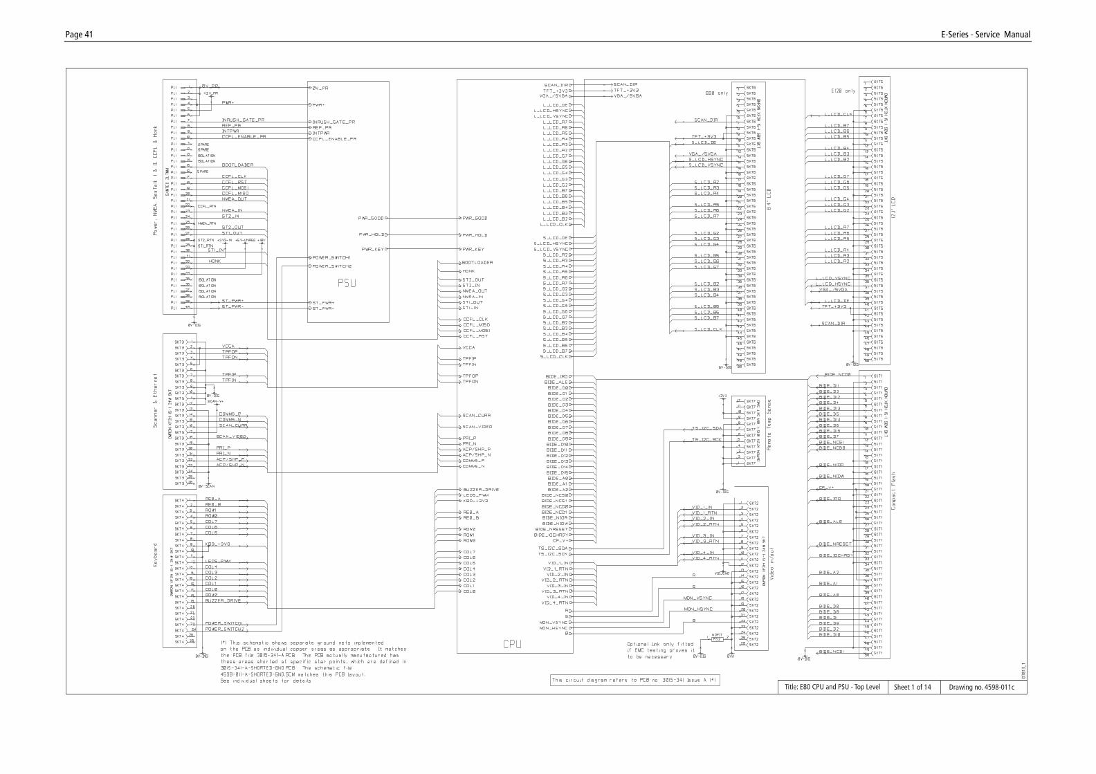
Page 41 E-Series - Service Manual
Title: E80 CPU and PSU - Top Level Drawing no. 4598-011cSheet 1 of 14
D781
3_1

Page 42 E-Series - Service Manual
Title: CPU/PSU - PSU Drawing no: 4598-011cSheet 2 of 14
D781
4_1

Page 43 E-Series - Service Manual
Title: CPU/PSU - Converter Drawing no: 4598-011cSheet 3 of 14
D781
5_1

Page 44 E-Series - Service Manual
Title: CPU top level Drawing no: 4598-011cSheet 4 of 14
D781
6_1

Page 45 E-Series - Service Manual
Title: E80 CPU/PSU - CPU power regulation Drawing no: 4598-011cSheet 5 of 14
D781
7_1

Page 46 E-Series - Service Manual
Title: E80 BTB SDRAM/Flash Memory Drawing no. 4598-011cSheet 6 of 14
D781
8_1

Page 47 E-Series - Service Manual
Title: E80 CPU/PSU - Scanner Interface Drawing no. 4598-011cSheet 7 of 14
D781
9_1

Page 48 E-Series - Service Manual
Title: E80 CPU/PSU - Ethernet and Serial Interface Drawing no. 4598-011cSheet 8 of 14
D782
0_1

Page 49 E-Series - Service Manual
Title: E80 CPU/PSU - Video Input Drawing no. 4598-011cSheet 9 of 14
D782
1_1

Page 50 E-Series - Service Manual
Title: E80 CPU/PSU - Keyboard Interface Drawing no. 4598-011cSheet 10 of 14
D782
2_1

Page 51 E-Series - Service Manual
Title: E80 CPU/PSU - Compact Flash Interface Drawing no. 4598-011cSheet 11 of 14
D782
3_1

Page 52 E-Series - Service Manual
Title: E80 CPU/PSU - Coral GDC and Memory D7824_1 (from drawing no. 4598-011C)Sheet 12 of 14

Page 53 E-Series - Service Manual
Title: E80 CPU/PSU - Analog Video and LCD out D7825_1 (from drawing no:.4598-011C)Sheet 13 of 14

Page 54 E-Series - Service Manual
Title: E80 CPU/PSU - Misc Pandora D7826_1(from drawing no. 4598-011C)Sheet 14 of 14

Page 55 E-Series - Service Manual
Title: E80 CPU/PSU - Surface mount component side Drawing no. 4598-010cSheet 1 of 3
D785
2_1

Page 56 E-Series - Service Manual
Title: E80 CPU/PSU - Conventional component side Drawing no. 4598-010cSheet 2 of 3
D785
3_1

Page 57 E-Series - Service Manual
Title: E80 CPU/PSU - Surface mount component underside Drawing no. 4598-010cSheet 3 of 3
D785
4_1

Page 58 E-Series - Service Manual
Title: E120 CPU/PSU - Surface mount component side Drawing no: 4598-016cSheet 1 of 3
D785
9_1

Page 59 E-Series - Service Manual
Title: E120 CPU/PSU - Conventional component side Drawing no: 4598-016cSheet 2 of 3
D786
0_1
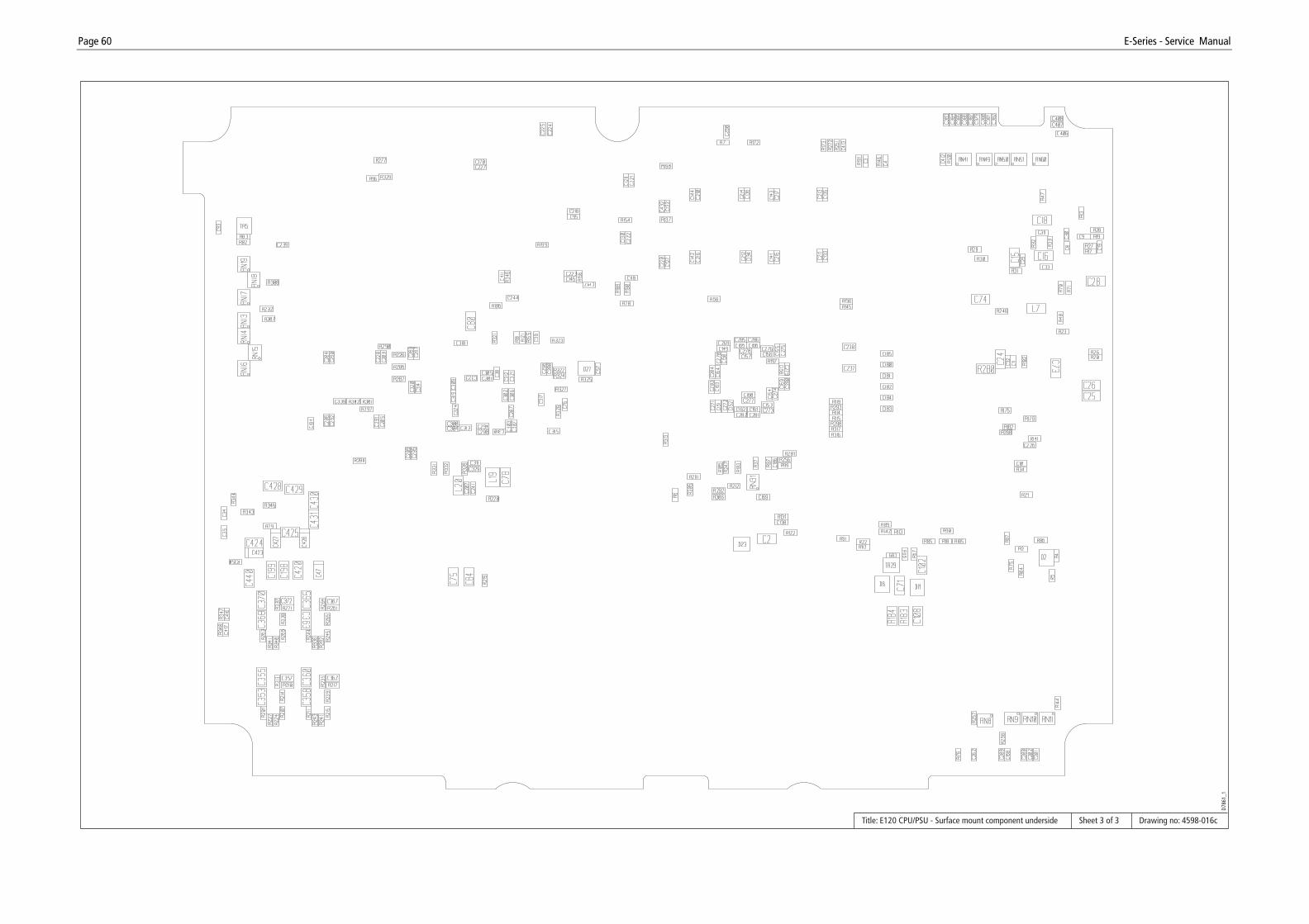
Page 60 E-Series - Service Manual
Title: E120 CPU/PSU - Surface mount component underside Drawing no: 4598-016cSheet 3 of 3
D786
1_1