service instructions - alpine home air products gmec96 service... · service instructions ......
TRANSCRIPT

RS6612013August 2014
This manual is to be used by qualified, professionally trained HVAC technicians only. Goodman does notassume any responsibility for property damage or personal injury due to improper service procedures orservices performed by an unqualified person. The material in this manual does not supercede manufacturersinstallation and operation instructions.
Copyright© 2014 Goodman Company, L.P.
Service InstructionsGoodman® Brand GMEC96 & Amana® Brand AMEC96
Two Stage Furnacewith multi-speed ECM Motor
® is a registered trademark of Maytag Corporation or its related companies andis used under license to Goodman Company, L.P., Houston, TX, USA. All rights reserved.

2
IMPORTANT INFORMATIONPride and workmanship go into every product to provide our customers with quality products. It is possible, however,that during its lifetime a product may require service. Products should be serviced only by a qualified service technicianwho is familiar with the safety procedures required in the repair and who is equipped with the proper tools, parts, testinginstruments and the appropriate service manual. REVIEW ALL SERVICE INFORMATION IN THE APPROPRIATESERVICE MANUAL BEFORE BEGINNING REPAIRS.
IMPORTANT NOTICES FOR CONSUMERS AND SERVICERS
RECOGNIZE SAFETY SYMBOLS, WORDS AND LABELS
TABLE OF CONTENTS
WARNING
HIGH VOLTAGEDISCONNECT ALL POWER BEFORE SERVICING ORINSTALLING THIS UNIT. MULTIPLE POWER SOURCES MAYBE PRESENT. FAILURE TO DO SO MAY CAUSE PROPERTYDAMAGE, PERSONAL INJURY OR DEATH.
GOODMAN WILL NOT BE RESPONSIBLE FOR ANY INJURY OR PROPERTY DAMAGE ARISING FROM IMPROPER SERVICE OR SERVICE PROCEDURES. IF YOU INSTALL OR PERFORM SERVICE ON THIS UNIT, YOU ASSUME RESPONSIBILITY FOR ANY PERSONAL INJURY OR PROPERTY DAMAGE WHICH MAY RESULT. MANY JURISDICTIONS REQUIRE A LICENSE TO INSTALL OR SERVICE HEATING AND AIR CONDITIONING EQUIPMENT.
TO PREVENT THE RISK OF PROPERTY DAMAGE, PERSONAL INJURY, OR DEATH, DO NOT STORE COMBUSTIBLE MATERIALS OR USE GASOLINE OR OTHER FLAMMABLE LIQUIDS OR VAPORS IN THE VICINITY OF THIS APPLIANCE.
IMPORTANT INFORMATION ......................... 2 - 6
PRODUCT IDENTIFICATION ........................ 7 - 8
INSTALLATION CONSIDERATIONS ........... 9 - 26
SYSTEM OPERATION ...............................27 - 33
ACCESSORIES ..........................................34 - 37
SERVICING TABLE OF COnTENTS ................. 38
SERVICING .. .............................................. 39 - 56
MAINTENANCE ............................................57- 58

3
IMPORTANT INFORMATION
To locate an authorized servicer, please consult your telephone book or the dealer from whom you purchased thisproduct. For further assistance, please contact:
CONSUMER INFORMATION LINE GOODMAN® BRAND PRODUCTS
TOLL FREE1-877-254-4729 (U.S. only)
email us at:[email protected]
fax us at: (731) 856-1821(Not a technical assistance line for dealers.)
CONSUMER INFORMATION LINEAMANA® BRAND PRODUCTS
TOLL FREE1-877-254-4729 (U.S. only)
email us at:[email protected]
fax us at: (731) 856-1821(Not a technical assistance line for dealers.)
Outside the U.S., call 1-713-861-2500.(Not a technical assistance line for dealers.) Your telephone company will bill you for the call.
DANGER
0140M00020-D
CARBON MONOXIDE POISONING HAZARDSpecial warning for installation of furnaces or air handling units in enclosed area such as garages, utility rooms or parking areas. Carbon monoxide producingdevices (such as automobile, space heater, gas water heater, etc.) Should not be operated in enclosed areas such as unventilated garages or utility rooms becauseof the danger of carbon monoxide (CO) poisoning resulting from the exhaust emissions. If a furnace or air handler is installed in an enclosed area and a carbonmonoxide producing device is operated therein, there must be adequate direct outside ventilation. Carbon monoxide emissions can be (re)circulated throughoutthe structure if the furnace or air handler is operating in any mode. CO can cause serious illness including permanent brain damage or death.
Avertissement special au sujet de l'installation d'appareils de chauffage ou de traitement d'air dans des endroits clos, tets les garages, les locaux d'entretien et lesRISQUE D'EMPOISONNEMENT AU MONOXYDE DE CARBONE
stationnements. Evitez de mettre en marche les appareils produisant du monoxyde de carbone (tels que les automobile, les appareils de chauffage autonome,etc.)dans des endroits non ventilés tels que les d'empoisonnement au monoxyde de carbone. Si vous devez faire fonctionner ces appareils dans un endroit clos, assures-vous qu'il y ait une ventilation directe provenant de l'exterie . Les émissions de monoxyde de carbone peuvent etre recircules dans les endroits clos, si l'appareil de chauffage ou de traitement d'air sont en marche. Le monoxyde de carbone peut causer des maladies graves telles que des dommages permanents au cerveau et meme la mort.
Advertencia especial para la instalación de calentadores ó maneja oras de aire en áreas cerradas como estacionamientos ó cuartos de servicio. Los equipos óRIESGO DE INTOXICACIÓN POR MONÓXIDO DE CARBONO
aparatos que producen monóxido de carbono (tal como automóvil, calentador de gas, calentador de agua por medio de gas, etc) no deben ser operados enáreas cerradas debido al riesgo de envenenamiento por monóxido de carbono (CO) que resulta de las emisiones de gases de combustión. Si el equipo óaparato se opera en dichas áreas, debe existir una adecuada ventilac ón directa al exterior. Las emisiones de monóxido de carbono pueden circular a travésdel aparato cuando se opera en cualquier modo. El monóxido de carbono puede causar enfermedades severas como daño cerebral permanente ó muerte.
DANGER
PELIGRO

4
gas. If you then smell gas, STOP!above on this label.Follow "B" in the safety informationabove on this label. If you don't smell
8. Move the gas control switch or knob
9. Replace control access panel.
gas, go to the next step.
technician or gas supplier.
11. Set the thermostat to the desired
12. If the appliance will not operate,
To Appliance" and call your service
5. Replace control access panel.to "OFF". Do not force.
follow the instructions "To Turn Off Gas
4. Move the gas control switch or knob
Do not store or use gasoline orother flammable vapors and liquids in the vicinity of this
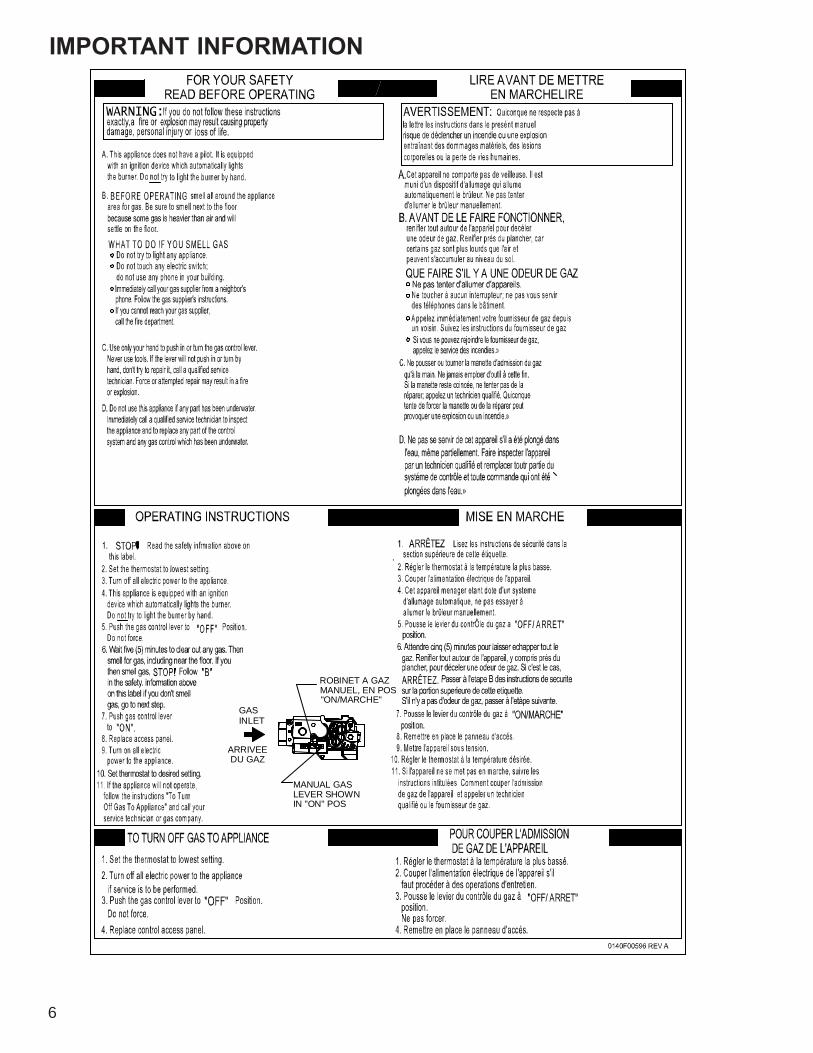
TO TURN OFF GAS TO APPLIANCE
10. Turn on all electric power to the
FOR YOUR SAFETY
or any other appliance.
2. Turn off all electric power to theappliance if service is to be performed.
1. Set the thermostat to its lowest setting.
3. Remove control access panel.
automatic ignition system which4. This appliance is equipped with an
3. Turn off all electric power to the2. Set the thermostat to lowest setting.
5. Remove control access panel.try to light the burners by hand.
6. Move the gas control switch or knob
automatically lights the burners. Do not
to "OFF".
appliance.
setting.
appliance.
to "ON".
0140F00001P
SWITCH SHOWNIN "ON" POSITION
GAS CONTROL
Force or attempted repair may result in
FOR YOUR SAFETY READ BEFORE OPERATING
call the fire department.
damage, personal injury or loss of life.
If you cannot reach your gas supplier,
a fire or explosion may result causing propertyIf you do not follow these instructions exactly,
which has been under water.
C. Use only your hand to move the gascontrol switch or knob. Never usetools. If the gas control switch or knob
D. Do not use this appliance if any parthas been under water. Immediately calla qualified service technician to inspectthe appliance and to replace any part ofthe control system and any gas control
7. Wait five (5) minutes to clear out any
will not operate, don't try to repair it,call a qualified service technician.
is heavier than air and will settle on the
Immediately call your supplier
the gas suppliers instructions.
WHAT TO DO IF YOU SMELL GASDo not try to light any appliance.Do not touch any electric switch;do not use any telephone in your
from a neighbor's phone. Follow
1. STOP! Read the safety information
OPERATING INSTRUCTIONS
floor.
building.
a fire or explosion.
try to light the burners by hand.
smell next to the floor because some gasthe appliance area for gas. Be sure toB. BEFORE OPERATING smell around
automatically lights the burners. Do notis equipped with an ignition device whichA. This appliance does not have a pilot. It
reproductive harm.This product containsfiberglass insulation.
cancer.California to cause
contains a chemicalFiberglass insulation
instructions and local
If notWARNING:
cause cancer, birthdefects or other
in fuel combustionyou to substances
death or seriouswhich can cause
State of California toare known to theillness and which
accordance with theand maintained in
instructions, thisproduct could expose
manufacturer's
installed, operated
For outdoorPGB & PGJ
For indoor installation.
of local codes, followcodes. In the absence
Code, ANSI Z223.1.the National Fuel Gas
installation only.
cause injury or
consult a qualified
Refer to the user'sinformation manualprovided with this
property damage.
This furnace must be
or the gas supplier.
alteration, service ormaintenance can
WARNING: Improper
IMPORTANT INFORMATION

5
IMPORTANT INFORMATIONCONSIGNES DE SECURITE - LIREAVANT D'ALLUMER L'APPAREIL
AVERTISSEMENT: Le non-respect des instructions qui suivent peutentrainer un risque d'incendie ou d'explosion causant des dommages,des blessures ou la mort.
A. Cet appareil comporte pas de veilleuse. Il est muni d'un mecanisme qui allumeautomatiquement le bruleur. N'allumez paz le bruleur manuellement.
B. Sentir tout autour de l'appariel AVANT D'ALLUMER afin de deceler toute fuite de gaz.Assurez-vous de sentir tout pres du plancher car certains gaz sont plus lourds que l'airet se deposeront sur le plancher.
SI VOUS SENTEZ UNE ODEUR DE GAZ:Ne tentez d'allumer aucun appariel.Ne touchez pas aux interrupteurs electriques; n'utiliser aucun telephonedans l'edifice ou vous vous trouvez.Appelez immediatement votre fournisseur de gaz en utilisant le telephoned'un voisin et suivez les instructions du fournisseur.Appelez les pompiers si vous ne parvenez pas a rejoindre votre fournisseurde gaz.
C. N'utiliser que votre main pour pousser ou tourner le commande du gaz. N'utilisezjamais d'outils. Si vous ne parvenez pas a pousser ou a tourner la commande, ne tentezpas de la reparer; appelez un reparateur qualifie. Forcer la commande ou essayer de lareparer peut entrainer un risque d'incendie ou d'explosion.
D. N'utilisez pas cet appareil si l'une de ses parties a ete dans l'eau. Si cela se produit,demandez immediatement a un reparateur qualifie d'inspecter l'appareil et de remplacertoute piece du systeme de controle et toute commande de gaz ayant ete dans l'eau.
0140F00002P
INSTRUCTIONS DE SERVICE1. UN INSTANT! Lisez d'abord les consignes
2. Reglez le thermostat a son point le plus bas.3. Coupez l'alimentation electrique de l'appareil.4. Cet appareil est muni d'un mecanisme qui allume automatiquement le bruleur. Ne tentez pas d'allumer le bruleur manuellement.5. Retirez le panneau d'acces de la commande.6. Mettez la commande de gaz a la position
7. Attendez cinq (5) minutes afin de permettre a tout gaz present d'etre evacue. Si vous sentez une odeur de gaz a ce moment, ARRETEZ! et suivez les consignes de securite donnees au
de gaz, passez a l'etape suivante.8. Mettez la commande de gaz a la position
en place.10. Retablissez l'alimenation electrique de l'appareil.11. Reglez le thermostat a le temperature desiree.12. Si l'appareil ne fonctionne pas, suivez les instructions intitulees "Arret du gaz" et appelez un reparateur qualifie ou votre fournisseur de gaz.
ARRET DU GAZ1. Reglez le thermostat a son point le plus bas.2. Coupez l'alimentation electrique de l'appareil si vous devez effectuer un entretien.3. Retirez le panneau d'acces de la commande.4. Mettez la commande de gaz a la position ARRET ("OFF").5. Remettez le panneau d'acces de la commande en place.
de securite ci-dessus.
ARRET ("OFF").
paragraphe B ci-dessus. Si vous ne sentez pas
MARCHE ("ON").9. Remettez la panneau d'acces de la commande
^ ^
^
^
^
^
^
^
^
^
^
^
^
Commande de
"MARCHE"gaz en position
6
DU
GAZARRIVEE
INLETGAS
IN
"ON"
POSLEVER
SHOWNMANUAL
GAS
"ON/MARCHE"MANUEL,
EN
POSROBINET
A
GAZ
IMPORTANT INFORMATION

PRODUCT IDENTIFICATION
7
The model and manufacturing number are used for positive identification of component parts used in manufacturing.Please use these numbers when requesting service or parts information.
* M E C 96 060 3 B N A A1 2 3 4 5,6 7,8,9 10 11 12 13 14
Brand
MotorNOx
AFUE
MBTU/h
A - Amanafi BrandG - Goodmanfi BrandA - Amana® BrandG - Goodman® Brand
MODEL # MFG. # DESCRIPTION
AMEC96
AMEC060302BNAA AMEC960402BNAA AMEC060603BNAA AMEC960803BNAA AMEC961004CNAA AMEC961205DNAA
Amana® Brand 96% Two Stage Heating / Two Stage Cooling Gas Furnace, Up flow/Horizontal Left and Right, 34.5" tall, Induced Draft, Nidec multi-speed ECM motor. Stainless Steel tubular heat exchanger. 115 volt s ilicon nitride igniter. Left or right gas ent
GMEC96
GMEC060302BNAA GMEC960402BNAA GMEC060603BNAA GMEC960803BNAA GMEC961004CNAA GMEC961205DNAA
Goodman ® Brand 96% Two Stage Heating / Two Stage Cooling Gas Furnace, Up flow/Horizontal Left and Right, 34.5" tall, Induced Draft, Nidec multi-speed ECM motor. Aluminized Steel tubular heat exchanger. 115 volt s ilicon nitride igniter. Left or right gas

PRODUCT IDENTIFICATION
8
MODEL # MFG # DESCRIPTION
AFE18-60A N/A
Fossil Fuel Kit. The AFE18-60A control is designed for use where the indoor coil is located above/downstream of a gas or fossil fuel furnace when used with a heat pump. It will operate with single and two stage heat pumps and single and two stage furnaces. The AFE18-60A control will turn the heat pump unit off when the furnace is turned on. An anti-short cycle feature initiates a 3 minute timed off delay when the compressor goes off.
AMU1620AMU1625AMU2020AMU2025
GMU1620GMU1625GMU2020GMU2025
P1251305FP1251306FP1251307FP1251308F
N/A
Media Air Cleaner. The Amana (AMU*) and Goodman (GMU*) Media Air Cleaner is a high efficiency air filtration device designed to remove dirt, dust, pollen and other microscopic particles from the air passing through it. Flexible performance range up to 2,000 CFM capacity. The air cleaner should be installed in the system so that all the system air is circulated through the air cleaner. The air cleaner will only remove the airborne contaminants delivered to it. Maximum performance is obtained when the system blower is set for continuous operation. Carbon filters (optional) are available.
ASAS-10ASAS-11ASAS-12ASAS-18
P1251301FP1251302FP1251303FP1251304F
Electronic Air Cleaner. The High-Efficiency Electronic Air Cleaner is designed to remove air contaminants down to .01 microns. Carbon filters (optional) remove odors. Dual indicator lights show unit operation at a glance. Electronic proving switch cycles the air cleaner On/Off with the system fan. Durable powder-coat paint finish resists corrosion.
DCVK-20
DCVK-30
P1254001F
P1254002F
Concentric Vent Kit. For use with Amana® Brand high efficiency furnace models . This kit is designed to allow terminations of a direct vent furnace to be "concentrically" vented through a wall or roof. This kit allows a single penetration to support terminations for both the vent/flue and the combustion air intake pipe. The DCVK-20 (2") and DCVK-30 (3") kits are certified for models listed above. See specification sheets on future models for use of the vent kit.
0170K00000S N/ASide Wall Only Concentric Vent Kit. For use with high efficiency furnace models . This kit is to be used with 2" - 3" vent systems. The vent kit must terminate outside the structure. This kit is NOT intended for use with single pipe (indirect vent) installations.
0170K00001S N/ASide Wall Only Concentric Vent Kit. For use with high efficiency 90% furnace models . This kit is to be used with 2" only vent systems. The vent kit must terminate outside the structure. This kit is NOT intended for use with single pipe (indirect vent) installations.
EFR02 P1221001P1221002F
External Filter Rack Kit. This kit is intended to provide a location, external to the furnace casing, for installation of a permanent filter. The rack is mounted over the indoor air blower compartment area of either side panel, and provide filter retention as well as a location for attaching return air ductwork.
LPLP03 N/A
LP Gas Low Pressure Kit. Designed for application on Goodman® and Amana® Brand's 80% and 90% single-stage and two-stage gas fired furnace products installed on LP gas listed in this manual. This kit includes harness adaptors to work with White-Rodgers single & two stage gas valves,Honeywell single and two-stage gas valves, as well as modulating gas valves.
RF000142 N/AVent Drain Coupling. For use when the furnaces is installed in horizontal left position and the internal elbow is removed.

INSTALLATION CONSIDERATIONS
9
IntroductionThis is a Category lV furnace. This furnace uses a pressur-ized venting system and must be installed per National andlocal codes requirements and the installation manual thatwas shipped with the furnace.The *MEC96 34.5" furnace is one of the products in ournewly redesigned line of shorter chassis furnaces. It is avail-able in the following sizes and suitable for up flow / horizon-tal installation.
*MEC960302BNAA*MEC960402BNAA*MEC960603BNAA*MEC960803BNAA*MEC961004CNAA*MEC961205DNAA
SafetyPlease adhere to the following warnings and cautions wheninstalling, adjusting, altering, servicing, or operating the fur-nace.
TO PREVENT PERSONAL INJURY OR DEATH DUE TO IMPROPER INSTALLATION,ADJUSTMENT, ALTERATION, SERVICE OR MAINTENANCE, REFER TO THISMANUAL. FOR ADDITIONAL ASSISTANCE OR INFORMATION, CONSULT AQUALIFIED INSTALLER, SERVICE AGENCY OR THE GAS SUPPLIER.
WARNING
WARNING
THIS PRODUCT CONTAINS OR PRODUCES A CHEMICAL OR CHEMICALS WHICHMAY CAUSE SERIOUS ILLNESS OR DEATH AND WHICH ARE KNOWN TO THESTATE OF CALIFORNIA TO CAUSE CANCER, BIRTH DEFECTS OR OTHERREPRODUCTIVE HARM.
WARNING
TO PREVENT POSSIBLE PROPERTY DAMAGE, PERSONAL INJURY OR DEATHDUE TO ELECTRICAL SHOCK, THE FURNACE MUST BE LOCATED TO PROTECTTHE ELECTRICAL COMPONENTS FROM WATER.
Charge (ESD) PrecautionsNOTE: Discharge body’s static electricity before touchingunit. An electrostatic discharge can adversely affect electri-cal components.Use the following precautions during furnace installation andservicing to protect the integrated control module from dam-age. By putting the furnace, the control, and the person atthe same electrostatic potential, these steps will help avoidexposing the integrated control module to electrostatic dis-charge. This procedure is applicable to both installed anduninstalled (ungrounded) furnaces.
1. Disconnect all power to the furnace. Do not touch theintegrated control module or any wire connected to thecontrol prior to discharging your body’s electrostaticcharge to ground.
2. Firmly touch a clean, unpainted, metal surface of thefurnace near the control. Any tools held in a person’shand during grounding will be discharged.
3. Service integrated control module or connecting wiringfollowing the discharge process in Step 2. Use cautionnot to recharge your body with static electricity; (i.e., donot move or shuffle your feet, do not touch ungroundedobjects, etc.). If you come in contact with an ungroundedobject, repeat Step 2 before touching control or wires.
4. Discharge any static electricity from your body to groundbefore removing a new control from its container. FollowSteps 1 through 3 if installing the control on a furnace.Return any old or new controls to their containers beforetouching any ungrounded object.
Product ApplicationThis product is designed for use as a residential home gasfurnace. It is not designed or certified for use in mobile home,trailer, or recreational vehicle applications.This furnace can be used in the following non-industrialcommercial applications: Schools, Office buildings, Churches,Retail stores, Nursing homes, Hotels/motels, Common oroffice areas. In such applications, the furnace must be installedwith the installation instructions.The *MEC96 furnaces are ETL certified appliances and areappropriate for use with natural or propane gas. (NOTE: Ifusing propane gas, a propane conversion kit is required).*MEC96 furnaces are dual certified.Dual certification means that the combustion air inlet pipe isoptional and the furnace can be vented as a:
Non-direct vent (single pipe) central forced air furnacein which combustion air is taken from the installationarea or from air ducted from the outside or,Direct vent (dual pipe) central forced air furnace in whichall combustion air supplied directly to the furnace burn-ers through a special air intake system outlined inthis manual and the installation instructions.
To ensure proper installation, operation and servicing, thor-oughly read the installation and service manuals for specif-ics pertaining to the installation, servicing and application ofthis product.
WARNING
POSSIBLE PROPERTY DAMAGE, PERSONAL INJURY OR DEATH DUE TO FIRE,EXPLOSION, SMOKE, SOOT, CONDENSTAION, ELECTRICAL SHOCK OR CARBONMONOXIDE MAY RESULT FROM IMPROPER INSTALLATION, REPAIR, OPERATION,OR MAINTENANCE OF THIS PRODUCT.

INSTALLATION CONSIDERATIONS
10
WARNING
TO PREVENT PROPERTY DAMAGE, PERSONAL INJURY OR DEATH DUE TO FIRE,DO NOT INSTALL THIS FURNACE IN A MOBILE HOME, TRAILER, OR RECREATIONALVEHICLE.
To ensure proper furnace operation, install, operate, main-tain and service the furnace in accordance with the installa-tion, operation and service instructions, all local buildingcodes and ordinances. In their absence, follow the latestedition of the National Fuel Gas Code (NFPA 54/ANSIZ223.1), and/or CAN/CGA B149 Installation Codes, localplumbing or waste water codes, and other applicable codes.A copy of the National Fuel Gas Code (NFPA 54/ANSIZ223.1) can be obtained from any of the following:
American National Standards Institute1430 BroadwayNew York, NY 10018National Fire Protection Association1 Batterymarch ParkQuincy, MA 02269
CSA International8501 East Pleasant ValleyCleveland, OH 44131
A copy of the CAN/CGA B149 Installation Codes can beobtained from:
CSA International178 Rexdale BoulevardEtobicoke, Ontario, Canada M9W, 1R3
The rated heating capacity of the furnace should be greaterthan or equal to the total heat loss of the area to be heated.The total heat loss should be calculated by an approvedmethod or in accordance with “ASHRAE Guide” or “ManualJ-Load Calculations” published by the Air Conditioning Con-tractors of America.
Location Requirements and Considerations
WARNING
TO PREVENT POSSIBLE EQUIPMENT DAMAGE, PROPERTY DAMAGE, PERSONALINJURY OR DEATH, THE FOLLOWING BULLET POINTS MUST BE OBSERVEDWHEN INSTALLING THE UNIT.
Follow the instructions listed below when selecting a fur-nace location. Refer also to the guidelines provided in theCombustion and Ventilation Air Requirements section inthis manual or the installation instructions for details.
• Centrally locate the furnace with respect to the pro-posed or existing air distribution system.
• Ensure the temperature of the return air entering thefurnace is between 55°F and 100°F when the furnaceis heating.
• If the furnace is installed in an application where thetypical operating sound level of a furnace is deemedobjectionable, an optional sound reduction kit is avail-able. Consult your local distributor for more details.
• Provide provisions for venting combustion productsoutdoors through a proper venting system. Specialconsideration should be given to vent/flue pipe routingand combustion air intake pipe when applicable.90% Furnaces: Refer to the Vent/Flue Pipe and Com-bustion Air Pipe -Termination Locations section in thismanual or the installation instructions for appropriatetermination locations. Also for 90% furnaces, refer tothe Vent/Flue Pipe and Combustion Air Pipe -Termi-nation Locations section in this manual or the instal-lation instructions to determine if the piping systemfrom furnace to termination can be accomplishedwithin the guidelines given.
NOTE: The length of flue and/or combustion air piping canbe a limiting factor in the location of the furnace.
• Locate the 90% furnace so that the condensate canbe piped at a downward slope away from the furnaceto the drain. Do not locate the furnace or its conden-sate drainage system in any area subject to belowfreezing temperatures without proper freeze protec-tion. Refer to the Condensate Drain Lines and Trapsection in this manual or the installation instructionsfor further details.
• Set the 90% furnace on a level floor to enable propercondensate drainage. If the floor becomes wet or dampat times, place the furnace above the floor on a con-crete base sized approximately 1-1/2" larger than thebase of the furnace. Refer to the Horizontal Applica-tions and Considerations section in this manual orthe installation instructions for leveling of horizontalfurnaces.
• Ensure upflow or horizontal furnaces are not installeddirectly on carpeting, or any other combustible mate-rial. The only combustible material allowed is wood.
• Exposure to contaminated combustion air will resultin safety and performance-related problems. Do notinstall the furnace where the combustion air is ex-posed to the following substances:
chlorinated waxes or cleanerschlorine-based swimming pool chemicalswater softening chemicalsdeicing salts or chemicalscarbon tetrachloridehalogen type refrigerants

INSTALLATION CONSIDERATIONS
11
cleaning solutions (such as perchloroethylene)printing inkspaint removersvarnisheshydrochloric acidcements and gluesantistatic fabric softeners for clothes dryersand masonry acid washing materials
• Isolate a non-direct vent furnace if it is installed nearan area frequently contaminated by any of the abovesubstances. This protects the non-direct vent furnacefrom airborne contaminants. To ensure that the en-closed non-direct vent furnace has an adequate sup-ply of combustion air, vent from a nearby uncontami-nated room or from outdoors. Refer to the Combus-tion and Ventilation Air Requirements section in thismanual or the installation instructions for details.
• If the furnace is used in connection with a coolingunit, install the furnace upstream or in parallel withthe cooling unit coil. Premature heat exchanger fail-ure will result if the cooling unit coil is placed in thereturn air of the furnace.
• If the furnace is installed in a residential garage, po-sition the furnace so that the burners and ignitionsource are located not less than 18 inches (457 mm)above the floor. Protect the furnace from physicaldamage by vehicles.
• If the furnace is installed horizontally, the furnace ac-cess doors must be vertical so that the burners firehorizontally into the heat exchanger. Do not installthe unit with the access doors on the “up/top” or “down/bottom” side of the furnace.
Clearances and AccessibilityInstallations must adhere to the clearances to combustiblematerials to which this furnace has been design certified.The minimum clearance information for this furnace is pro-vided on the unit’s clearance label. These clearances mustbe permanently maintained. Refer to Specification Sheet forminimum clearances to combustible materials. Clearancesmust also accommodate an installation’s gas, electrical,and drain trap and drain line connections. If the alternatecombustion air intake or vent/flue connections are used ona 90% furnace, additional clearances must be provided toaccommodate these connections. Refer to Vent Flue Pipeand Combustion Air Pipe section in this manual or the in-stallation instructions for details. NOTE: In addition to therequired clearances to combustible materials, a minimumof 24 inches service clearance must be available in front ofthe unit.A furnace installed in a confined space (i.e., a closet orutility room) must have two ventilation openings with a totalminimum free area of 0.25 square inches per 1,000 BTU/hrof furnace input rating. One of the ventilation openings mustbe within 12 inches of the top; the other opening must bewithin 12 inches of the bottom of the confined space. In atypical construction, the clearance between the door anddoor frame is usually adequate to satisfy this ventilationrequirement.
POSITION SIDES REAR FRONT BOTTOM FLUE TOPUpflow 0" 0" 1" C 0" 1"
Horizontal 6" 0" 1" C 0" 4"
MINIMUM CLEARANCES TO COMBUSTIBLE MATERIALS
• C = if placed on combustible floor, the floor MUST be wood ONLY.• For servicing or cleaning, a 24" front clearance is recommended.• Unit connections (electrical, flue, and drain) may necessitate greater clearances than the minimum clearances listed above• In all case, accessibility clearance must take precedence over from the enclosure where accessitility clearances are greater.• Approved for l ine contact in the horizontal position.
INSTALLATION CONSIDERATIONS
12
f. After it has been determined that each appliance connected to theventing system properly vents when tested as outlined above,return doors, windows, exhaust fans, fireplace dampers and anyother gas burning appliance to their previous conditions of use;
g. If improper venting is observed during any of the above tests, thecommon venting system must be corrected.
Corrections must be in accordance with the latest edition ofthe National Fuel Gas Code NFPA 54/ANSI Z223.1 and/orCSA B149 Installation Codes.If resizing is required on any portion of the venting system,use the appropriate table in Appendix G in the latest editionof the National Fuel Gas Code ANSI Z223.1 and/or CSA B149Installation Codes.
Thermostat RequirementsA two stage heat/cool thermostat is recommended. A singlestage heating thermostat may be used. It is recommendedthat a high quality thermostat with a "C" terminal is used tooperate the furnace.
Thermostat LocationIn an area having good air circulation, locate the thermostatabout five feet high on a vibration-free inside wall. Do notinstall the thermostat where it may be influenced by any ofthe following:
• Drafts, or dead spots behind doors, in corners, or un-der cabinets.
• Hot or cold air from registers.• Radiant heat from the sun.• Light fixtures or other appliances.• Radiant heat from a fireplace.• Concealed hot or cold water pipes, or chimneys.• Unconditioned areas behind the thermostat and de-
humidistat, such as an outside wall.
COMBUSTION AND VENTILATION AIRREQUIREMENTS
WARNING
POSSIBLE PROPERTY DAMAGE, PERSONAL INJURY OR DEATH MAY OCCURIF THE FURNACE IS NOT PROVIDED WITH ENOUGH FRESH AIR FOR PROPERCOMBUSTION AND VENTILATION OF FLUE GASES. MOST HOMES REQUIREOUTSIDE AIR BE SUPPLIED TO THE FURNACE AREA.
Improved construction and additional insulation in buildingshave reduced heat loss by reducing air infiltration and es-cape around doors and windows. These changes have helpedin reducing heating/cooling costs but have created a prob-lem supplying combustion and ventilation air for gas firedand other fuel burning appliances. Appliances that pull airout of the house (clothes dryers, exhaust fans, fireplaces,etc.) increase the problem by starving appliances for air.When the furnace is installed as a direct ven (2-pipe) fur-nace, no special provisions for air for combustion are re-quired. However, if this furnace is to be installed in the same
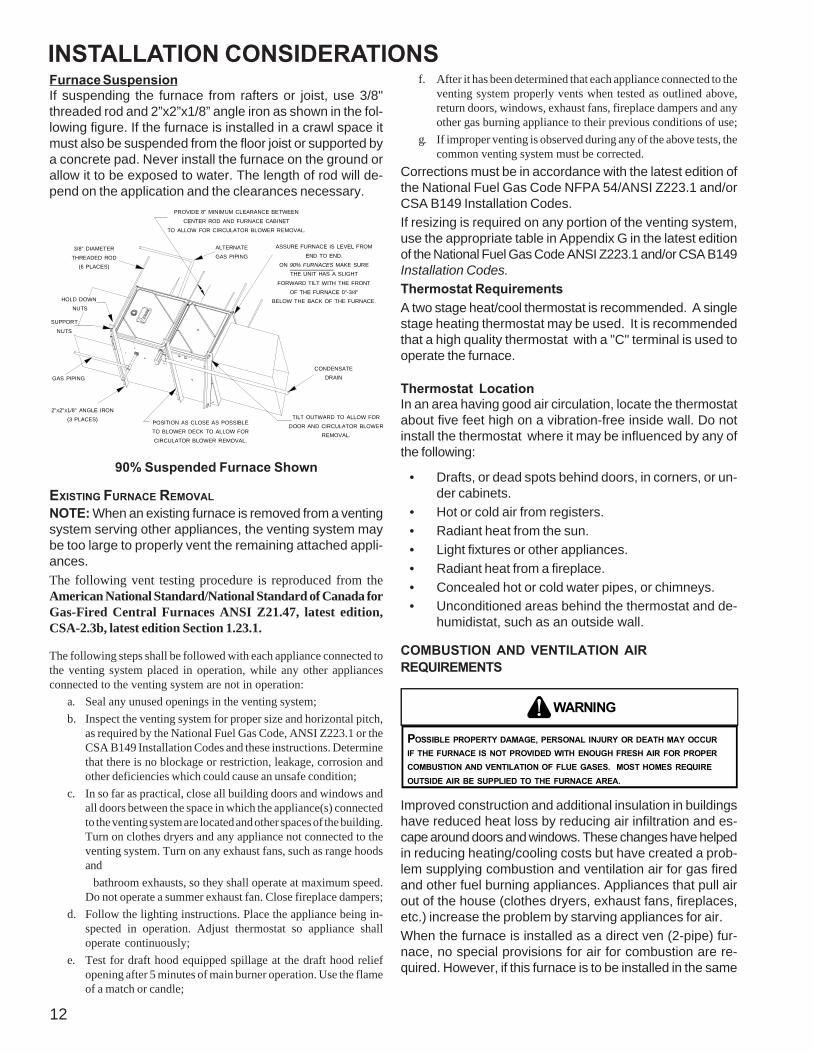
Furnace SuspensionIf suspending the furnace from rafters or joist, use 3/8"threaded rod and 2”x2”x1/8” angle iron as shown in the fol-lowing figure. If the furnace is installed in a crawl space itmust also be suspended from the floor joist or supported bya concrete pad. Never install the furnace on the ground orallow it to be exposed to water. The length of rod will de-pend on the application and the clearances necessary.
TILT OUTWARD TO ALLOW FORDOOR AND CIRCULATOR BLOWER
REMOVAL.
3/8" DIAMETER THREADED ROD
(6 PLACES)
PROVIDE 8" MINIMUM CLEARANCE BETWEEN
CENTER ROD AND FURNACE CABINETTO ALLOW FOR CIRCULATOR BLOWER REMOVAL.
ASSURE FURNACE IS LEVEL FROM
END TO END.ON 90% FURNACES MAKE SURE
THE UNIT HAS A SLIGHT
FORWARD TILT WITH THE FRONTOF THE FURNACE 0"-3/4"
BELOW THE BACK OF THE FURNACE.
POSITION AS CLOSE AS POSSIBLETO BLOWER DECK TO ALLOW FOR CIRCULATOR BLOWER REMOVAL.
2"X2"X1/8" ANGLE IRON(3 PLACES)
HOLD DOWN NUTS
SUPPORT
NUTS
CONDENSATEDRAINGAS PIPING
ALTERNATEGAS PIPING
90% Suspended Furnace Shown
EXISTING FURNACE REMOVALNOTE: When an existing furnace is removed from a ventingsystem serving other appliances, the venting system maybe too large to properly vent the remaining attached appli-ances.The following vent testing procedure is reproduced from theAmerican National Standard/National Standard of Canada forGas-Fired Central Furnaces ANSI Z21.47, latest edition,CSA-2.3b, latest edition Section 1.23.1.
The following steps shall be followed with each appliance connected tothe venting system placed in operation, while any other appliancesconnected to the venting system are not in operation:
a. Seal any unused openings in the venting system;b. Inspect the venting system for proper size and horizontal pitch,
as required by the National Fuel Gas Code, ANSI Z223.1 or theCSA B149 Installation Codes and these instructions. Determinethat there is no blockage or restriction, leakage, corrosion andother deficiencies which could cause an unsafe condition;
c. In so far as practical, close all building doors and windows andall doors between the space in which the appliance(s) connectedto the venting system are located and other spaces of the building.Turn on clothes dryers and any appliance not connected to theventing system. Turn on any exhaust fans, such as range hoodsand
bathroom exhausts, so they shall operate at maximum speed.Do not operate a summer exhaust fan. Close fireplace dampers;
d. Follow the lighting instructions. Place the appliance being in-spected in operation. Adjust thermostat so appliance shalloperate continuously;
e. Test for draft hood equipped spillage at the draft hood reliefopening after 5 minutes of main burner operation. Use the flameof a match or candle;

INSTALLATION CONSIDERATIONS
13
space with other gas appliances, such as a water heater,ensure there is an adequate supply of combustion and ven-tilation air for the other appliances. Refer to the latest edi-tion of the National Fuel Gas Code NFPA 54/ANSI Z223.1(Section 9.3), or CAN/CGA B149 Installation Codes (Sec-tions 7.2, 7.3, or 7.4), or applicable provisions of the localbuilding codes for determining the combustion air require-ments for the appliances.Most homes will require outside air be supplied to the fur-nace area by means of ventilation grilles or ducts connect-ing directly to the outdoors or spaces open to the outdoorssuch as attics or crawl spaces.The following information on air for combustion and ventilationis reproduced from the National Fuel Gas Code NFPA 54/ANSIZ223.1 Section 9.3.9.3* Air for Combustion and Ventilation.
9.3.1 General.
9.3.1.1 Air for combustion, ventilation, and dilution of flue gases forappliances installed in buildings shall be obtained by application of oneof the methods covered in 9.3.2 through 9.3.6. Where the requirementsof 9.3.2 are not met, outdoor air shall be introduced in accordance withmethods covered in 9.3.3 through 9.3.6.
Exception No. 1: This provision shall not apply to direct vent appliances.
9.3.1.2 Appliances of other than natural draft design and other thanCategory 1 vented appliances shall be provided with combustion, ven-tilation, and dilution air in accordance with the appliance manufacturer’sinstructions.
9.3.1.3 Appliances shall be located so as not to interfere with propercirculation of combustion, ventilation, and dilution air.
9.3.1.4 Where used, a draft hood or a barometric draft regulator shall beinstalled in the same room or enclosure as the appliance served so as toprevent any difference in pressure between the hood or regulator and thecombustion air supply.
9.3.1.5 Makeup air requirements for the operation of exhaust fans, kitchenventilation systems, clothes dryers, and fireplaces shall be considered indetermining the adequacy of a space to provide combustion air require-ments.
9.3.2 Indoor Combustion Air. The required volume of indoor air shallbe determined in accordance with the method in 9.3.2.1 or 9.3.2.2 ex-cept that where the air infiltration rate is known to be less than 0.40ACH, the method in 9.3.2.2 shall be used. The total required volumeshall be the sum of the required volume calculated for all applianceslocated within the space. Rooms communicating directly with the spacein which the appliances are installed through openings not furnishedwith doors, and through combustion air openings sized and located inaccordance with 9.3.2.3, are considered a part of the required volume.9.3.2.1* Standard Method. The minimum required volume shall be 50ft 3 per 1,000/Btu/hour (4.8m3/kW).
9.3.2.2* Known Air Infiltration Rate Method. Where the air infiltra-tion rate of a structure is known, the minimum required volume shall bedetermined as follows:
(1) For appliances other than fan-assisted, calculate using the followingequation:
21 ft3 I otherRequired Volume other > ________ _________ACH 1000 Btu/hr
(2) For fan-assisted appliances, calculate using the following equation:15 ft3 I fanRequired Volume fan > ________ _________
ACH 1000 Btu/hr
where:I other = all appliances other than fan-assisted input in Btu per
hour
I fan = fan-assisted appliances input in Btu per hour
ACH = air change per hour (percent of volume of space exchangedper hour, expressed as a decimal)
(3) For purposes of this calculation, an infiltration rate greater than0.60 ACH shall not be used in the equations in 9.3.2.2(1) and9.3.2.2(2).
9.3.2.3 Indoor Opening Size and Location. Openings used to con-nect indoor spaces shall be sized and located in accordance with thefollowing:
(1)*Combining spaces on the same story. Each opening shall have aminimum free area of 1 in.2/1000Btu/hr (2200 mm2/kW) of the totalinput rating of all appliances in the space but not less than 100 in.2
(0.60m2). One opening shall commence within 12 in. (300 mm) ofthe top, and one opening shall commence within 12 in. (300 mm) ofthe bottom, of the enclosure [see Figure A.9.3.2.3(1)]. The mini-mum dimension of air openings shall be not less than 3 in. (80 mm).
Furnace
WaterHeater
Opening
Chimney or Gas Vent
Opening
NOTE: Each opening must havea free area of not less than one square inch per 1000 BTU of the total input rating of all equip-ment in the enclosure, but notless than 100 square inches.
Figure A.9.2.3.3.(1) All Combustion Air from AdjacentIndoor Spaces through Indoor Combustion Air Openings.
(2) Combining spaces in different stories. The volumes of spaces indifferent stories shall be considered as communicating spaces wheresuch spaces are connected by one or more openings in doors orfloors having a total minimum free area of 2 in.2/1000 Btu/hr (4400mm2/kW) of total input rating of all appliances.
9.3.3 Outdoor Combustion Air. Outdoor combustion air shall beprovided through opening(s) to the outdoors in accordance with themethods in 9.3.3.1 or 9.3.3.2. The minimum dimension of air openingsshall not be less than 3 in. (80 mm).
( )
( )

INSTALLATION CONSIDERATIONS
14
9.3.3.1 Two Permanent Openings Method. Two permanent open-ings, one commencing within 12 in. (300 mm) of the top and one com-mencing within 12 in. (300 mm) of the bottom, of the enclosure shall beprovided. The openings shall communicate directly, or by ducts, withthe outdoors or spaces that freely communicate with the outdoors, asfollows:
(1)*Where directly communicating with the outdoors or where commu-nicating to the outdoors through vertical ducts, each opening shallhave a minimum free area of 1 in.2/4000 Btu/hr (550 min2/kW) oftotal input rating of all appliances in the enclosure. [See FigureA.9.3.3.1(1)(a) and Figure A.9.3.3.1(1)(b).]
Furnace
WaterHeater
Outlet Air
Chimney or Gas Vent
NOTE: The inlet and outlet airopenings must each have a freearea of not less than one squareinch per 4000 BTU of thetotal input rating of all equipmentin the enclosure.
Inlet Air
Ventilation louvers forunheated crawl space
Alternateair inlet
Ventilation louvers(each end of attic)
Figure A.9.3.3.1(1)(a) All Combustion Air From Outdoors -Inlet Air from Ventilated Crawl Space and Outlet Air
to Ventilated Attic.
Furnace
WaterHeater
Outlet Air
Chimney or Gas Vent
NOTE: The inlet and outlet airopenings must each have a freearea of not less than one squareinch per 4000 BTU of thetotal input rating of all equipmentin the enclosure.
Inlet air duct[ends 1 ft (300 mm)above floor]
Ventilation louvers(each end of attic)
Figure A.9.3.3.1(1)(b) All Combustion AirFrom Outdoors through Ventilated Attic.
(2)*Where communicating with the outdoors through horizontal ducts,each opening shall have a minimum free area of 1 in.2/2000 Btu/hr(1100 min2/kW) of total input rating of all appliances in the enclo-sure. [See Figure A.9.3.3.1(2).]
FurnaceWaterHeater
Chimney or Gas Vent
NOTE: The air duct openingsmust have a free area of notless than one square inch per2000 BTU of the total inputrating of all equipment in theenclosure*.Outlet air duct
Inlet air duct
Figure A.9.3.3.1(2) All Combustion Air From Outdoorsthrough Horizontal Ducts.
9.3.3.2* One Permanent Opening Method. One permanent open-ings, commencing within 12 in. (300 mm) of the top of the enclosure,shall be provided. The appliance shall have clearances of at least 1 in.(25 mm) from the sides and back and 6 in. (150 mm) from the front ofthe appliance. The opening shall directly communicate with the out-doors or shall communicate through a vertical or horizontal duct to theoutdoors or spaces that freely communicate with the outdoors (seeFigure A.9.3.3.2) and shall have a minimum free area of the following:(1) 1 in.2/3000 Btu/hr (700 mm2 per kW) of the total input rating of all
appliances located in the enclosure, and(2) Not less than the sum of the areas of all vent connectors in the
space.
Furnace
WaterHeater
Opening
Chimney or Gas VentNOTE: The single opening must havea free area of not less than one square inch per 3000 BTU of the total input rating of all equip-ment in the enclosure, but not less than the sum of the areas of all ventconnectors in the confined space.
AlternateOpeningLocation
Figure A.9.3.3.2 All Combustion AirFrom Outdoors through Single Combustion Air Opening.
9.3.4 Combination Indoor and Outdoor Combustion Air. The useof a combination of indoor and outdoor combustion air shall be inaccordance with (1) through (3) (see example calculation in Annex J]:
(1) Indoor Openings: Where used, openings connecting the interiorspaces shall comply with 9.3.2.3.
(2) Outdoor Opening(s) Location. Outdoor opening(s) shall be lo-cated in accordance with 9.3.3.
(3) Outdoor Opening(s) Size. The outdoor opening(s) size shall becalculated in accordance with the following:(a) The ratio of the interior spaces shall be the available volume
of all communicating spaces divided by the required volume.(b) The outdoor size reduction factor shall be 1 minus the ratio
of interior spaces.
INSTALLATION CONSIDERATIONS
15
(c) The minimum size of outdoor opening(s) shall be the full sizeof outdoor opening(s) calculated in accordance with 9.3.3,multiplied by the reduction factor. The minimum dimensionof air openings shall not be less than 3 in. (80 mm).
9.3.5 Engineered Installations. Engineered combustion air installa-tions shall provide an adequate supply of combustion, ventilation, anddilution air and shall be approved by the authority having jurisdiction.
9.3.6 Mechanical Combustion Air Supply. Where all combustion airis provided by a mechanical air supply system, the combustion air shallbe supplied form outdoors at the minimum rate of 0.35 ft3/min per1000 Btu/hr (0.034 m3/min per kW) for all appliances located withinthe space.
9.3.6.1 Where exhaust fans are installed, additional air shall be providedto replace the exhausted air.
9.3.6.2 Each of the appliances served shall be interlocked to the me-chanical air supply system to prevent main burner operation where themechanical air supply system is not in operation.
9.3.6.3 Where combustion air is provided by the building’s mechanicalventilation system, the system shall provide the specified combustionair rate in addition to the required ventilation air.
9.3.7 Louvers, Grilles, and Screens.
9.3.7.1 Louvers and Grilles. The required size of openings for com-bustion, ventilation, and dilution air shall be based on the net free areaof each opening. Where the free area through a design of louver or grilleor screen is known, it shall be used in calculating the size openingrequired to provide the free area specified. Where the louver and grilledesign and free area are not known, it shall be assumed that woodlouvers will have 25 percent free area, and metal louvers and grilles willhave 75 percent free area. Nonmotorized louvers and grilles shall befixed in the open position.
9.3.7.2 Minimum Scree Mesh Size. Screens shall not be smaller than1/4 in. mesh.
9.3.7.3 Motorized Louvers. Motorized louvers shall be interlockedwith the appliance so they are proven in the full open position prior tomain burner ignition and during main burner operation. Means shall beprovided to prevent the main burner form igniting should the louver failto open during burner startup and to shut down the main burner if thelouvers close during burner operation.
9.3.8 Combustion Air Ducts. Combustion air ducts shall comply with9.3.8.1 through 9.3.8.8.
9.3.8.1 Ducts shall be constructed of galvanized steel or a materialhaving equivalent corrosion resistance, strength, and rigidity.
Exception: Within dwellings units, unobstructed stud and joist spacesshall not be prohibited from conveying combustion air, provided thatnot more than one fireblock is removed.
9.3.8.2 Ducts shall terminate in an unobstructed space, allowing freemovement of combustion air to the appliances.
9.3.8.3 Ducts shall serve a single space.
9.3.8.4 Ducts shall not serve both upper and lower combustion airopenings where both such openings are used. The separation betweenducts servicing upper and lower combustion air openings shall be main-tained to the source of combustion air.
9.3.8.5 Ducts shall not be screened where terminating in an attic space.
9.3.8.6 Horizontal upper combustion air ducts shall not slope down-ward toward the source of combustion air.
9.3.8.7 The remaining space surrounding a chimney liner, gas vent,special gas vent, or plastic piping installed within a masonry, metal, orfactory built chimney shall not be used to supply combustion air.
Exception: Direct vent appliances designed for installation in a solidfuel-burning fireplace where installed in accordance with themanufacture’s installation instructions.
9.3.8.8 Combustion air intake openings located on the exterior of thebuilding shall have the lowest side of the combustion air intake open-ings located at least 12 in. (300 mm) vertically from the adjoining gradelevel.
Horizontal Applications and ConsiderationsHorizontal applications, in particular, may dictate many ofthe installation’s specifics such as airflow direction, duct-work connections, flue and/or combustion air pipe connec-tions, etc. The basic application of this furnace as a hori-zontal furnace differs only slightly from an upright installa-tion.
Horizontal Installations1. Horizontal installations require 5.5" under the furnace
to accommodate the drain trap.2. Horizontal furnaces must be installed with ¾” slope from
back to front to permit condensate flow towards thefront of the furnace.
When installing a *MEC96 horizontally with the left sidedown, there are two options for connecting the vent pipe tothe furnace.1. Venting may be connected to the furnace vent pipe fit-
ting on the original top (now the end) of the furnace2. The internal vent pipe and elbow may be removed from
the furnace to permit the vent to exit the top (originalside) of the furnace. If this option is used, an RF000142Vent-Drain coupling must be used to keep condensatefrom collecting in the inducer assembly
Refer to the following instructions and illustration.
INSTALLATION CONSIDERATIONS
16
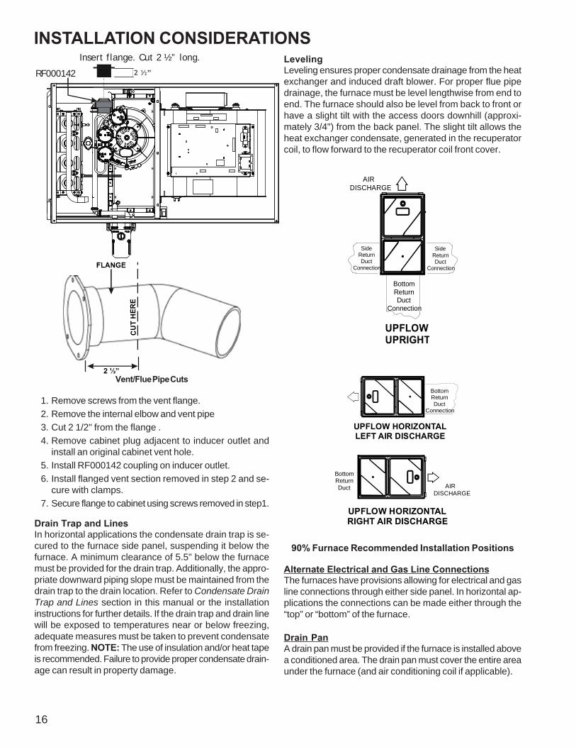
Insert flange. Cut 2 ½” long.
R 000142F
CU
T H
ERE
Vent/Flue Pipe Cuts
1. Remove screws from the vent flange.2. Remove the internal elbow and vent pipe3. Cut 2 1/2" from the flange .4. Remove cabinet plug adjacent to inducer outlet and
install an original cabinet vent hole.5. Install RF000142 coupling on inducer outlet.6. Install flanged vent section removed in step 2 and se-
cure with clamps.7. Secure flange to cabinet using screws removed in step1.
Drain Trap and LinesIn horizontal applications the condensate drain trap is se-cured to the furnace side panel, suspending it below thefurnace. A minimum clearance of 5.5" below the furnacemust be provided for the drain trap. Additionally, the appro-priate downward piping slope must be maintained from thedrain trap to the drain location. Refer to Condensate DrainTrap and Lines section in this manual or the installationinstructions for further details. If the drain trap and drain linewill be exposed to temperatures near or below freezing,adequate measures must be taken to prevent condensatefrom freezing. NOTE: The use of insulation and/or heat tapeis recommended. Failure to provide proper condensate drain-age can result in property damage.
LevelingLeveling ensures proper condensate drainage from the heatexchanger and induced draft blower. For proper flue pipedrainage, the furnace must be level lengthwise from end toend. The furnace should also be level from back to front orhave a slight tilt with the access doors downhill (approxi-mately 3/4") from the back panel. The slight tilt allows theheat exchanger condensate, generated in the recuperatorcoil, to flow forward to the recuperator coil front cover.
AIR DISCHARGE
Bottom Return Duct
Connection
SideReturnDuct
Connection
SideReturnDuct
Connection
UPFLOWUPRIGHT
Bottom Return Duct
Connection
UPFLOW HORIZONTALLEFT AIR DISCHARGE
Bottom Return Duct AIR
DISCHARGE
UPFLOW HORIZONTALRIGHT AIR DISCHARGE
90% Furnace Recommended Installation Positions
Alternate Electrical and Gas Line ConnectionsThe furnaces have provisions allowing for electrical and gasline connections through either side panel. In horizontal ap-plications the connections can be made either through the“top” or “bottom” of the furnace.
Drain PanA drain pan must be provided if the furnace is installed abovea conditioned area. The drain pan must cover the entire areaunder the furnace (and air conditioning coil if applicable).
INSTALLATION CONSIDERATIONS
17
Freeze ProtectionIf the drain trap and drain line will be exposed to tempera-tures near or below freezing, adequate measures must betaken to prevent condensate from freezing. NOTE: The useof insulation and/or heat tape is recommended. Failure toprovide proper condensate drainage can result in propertydamage.
Propane Gas and/or High Altitude Installations
WARNING
POSSIBLE PROPERTY DAMAGE, PERSONAL INJURY OR DEATH MAY OCCUR IFTHE CORRECT CONVERSION KITS ARE NOT INSTALLED. THE APPROPRIATE KITSMUST BE APPLIED TO INSURE SAFE AND PROPER FURNACE OPERATION. ALLCONVERSIONS MUST BE PERFORMED BY A QUALIFIED INSTALLER OR SERVICEAGENCY.
This furnace is shipped from the factory configured for natu-ral gas at standard altitude. Propane gas installations re-quire an orifice change to compensate for the energy con-tent difference between natural and propane gas.High altitude installations may require both a pressure switchand an orifice change. These changes are necessary to com-pensate for the natural reduction in the density of both thegas fuel and the combustion air at higher altitude.Refer to the Accessories Charts in this manual or productSpecification Sheet for a tabular listing of appropriatemanufacturer’s kits for propane gas and/or high altitude in-stallations. The indicated kits must be used to insure safeand proper furnace operation. All conversions must be per-formed by a qualified installer, or service agency.
VENT/FLUE PIPE AND COMBUSTION AIR PIPE
ONLY)
WARNING
FAILURE TO FOLLOW THESE INSTRUCTIONS CAN RESULT IN BODILY INJURY ORDEATH. CAREFULLY READ AND FOLLOW ALL INSTRUCTIONS GIVEN IN THISSECTION.
WARNING
UPON COMPLETION OF THE FURNACE INSTALLATION, CAREFULLY INSPECT THEENTIRE FLUE SYSTEM BOTH INSIDE AND OUTSIDE THE FURNACE TO ASSURE ITIS PROPERLY SEALED. LEAKS IN THE FLUE SYSTEM CAN RESULT IN SERIOUSPERSONAL INJURY OR DEATH DUE TO EXPOSURE TO FLUE PRODUCTS,INCLUDING CARBON MONOXIDE.
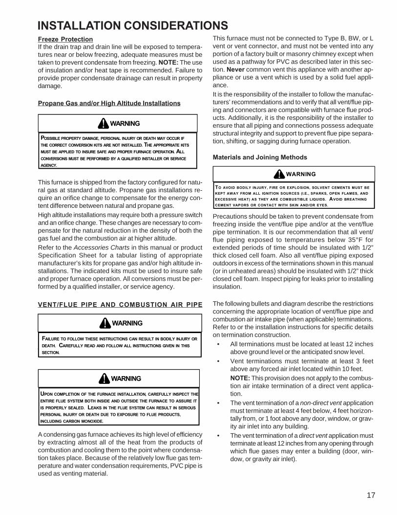
A condensing gas furnace achieves its high level of efficiencyby extracting almost all of the heat from the products ofcombustion and cooling them to the point where condensa-tion takes place. Because of the relatively low flue gas tem-perature and water condensation requirements, PVC pipe isused as venting material.
This furnace must not be connected to Type B, BW, or Lvent or vent connector, and must not be vented into anyportion of a factory built or masonry chimney except whenused as a pathway for PVC as described later in this sec-tion. Never common vent this appliance with another ap-pliance or use a vent which is used by a solid fuel appli-ance.It is the responsibility of the installer to follow the manufac-turers’ recommendations and to verify that all vent/flue pip-ing and connectors are compatible with furnace flue prod-ucts. Additionally, it is the responsibility of the installer toensure that all piping and connections possess adequatestructural integrity and support to prevent flue pipe separa-tion, shifting, or sagging during furnace operation.
Materials and Joining Methods
WARNING
TO AVOID BODILY INJURY, FIRE OR EXPLOSION, SOLVENT CEMENTS MUST BEKEPT AWAY FROM ALL IGNITION SOURCES (I.E., SPARKS, OPEN FLAMES, ANDEXCESSIVE HEAT) AS THEY ARE COMBUSTIBLE LIQUIDS. AVOID BREATHINGCEMENT VAPORS OR CONTACT WITH SKIN AND/OR EYES.
Precautions should be taken to prevent condensate fromfreezing inside the vent/flue pipe and/or at the vent/fluepipe termination. It is our recommendation that all vent/flue piping exposed to temperatures below 35°F forextended periods of time should be insulated with 1/2”thick closed cell foam. Also all vent/flue piping exposedoutdoors in excess of the terminations shown in this manual(or in unheated areas) should be insulated with 1/2” thickclosed cell foam. Inspect piping for leaks prior to installinginsulation.
The following bullets and diagram describe the restrictionsconcerning the appropriate location of vent/flue pipe andcombustion air intake pipe (when applicable) terminations.Refer to or the installation instructions for specific detailson termination construction.
• All terminations must be located at least 12 inchesabove ground level or the anticipated snow level.
• Vent terminations must terminate at least 3 feetabove any forced air inlet located within 10 feet.NOTE: This provision does not apply to the combus-tion air intake termination of a direct vent applica-tion.
• The vent termination of a non-direct vent applicationmust terminate at least 4 feet below, 4 feet horizon-tally from, or 1 foot above any door, window, or grav-ity air inlet into any building.
• The vent termination of a direct vent application mustterminate at least 12 inches from any opening throughwhich flue gases may enter a building (door, win-dow, or gravity air inlet).
INSTALLATION CONSIDERATIONS
18
• The vent termination of vent pipe run vertically througha roof must terminate at least 12 inches above theroof line (or the anticipated snow level) and be at least12 inches from any vertical wall (including any antici-pated snow build up).
• A vent termination shall not terminate over public walk-ways or over an area where condensate or vapor couldcreate a nuisance or hazard or could be detrimentalto the operation of regulators, relief valves, or otherequipment.
• The combustion air intake termination of a direct ventapplication should not terminate in an area which isfrequently dusty or dirty.
NOTE: In Canada, the B149 Fuel Gas Code takes prece-dence over the preceding termination restrictions.
12"
12"
NON-DIRECT VENTVENT/FLUE TERMINATION
NO TERMINATIONS ABOVE WALKWAY
12"
4'
4'
NON-DIRECT VENTVENT/FLUE TERMINATION
DIRECT VENTVENT/FLUE TERMINATION
12"
10'
3"
FORCED AIRINLET
OTHER THAN COMBUSTION AIR
TERMINATION INTAKE
GRADE OR HIGHEST ANTICIPATED SNOW LEVEL
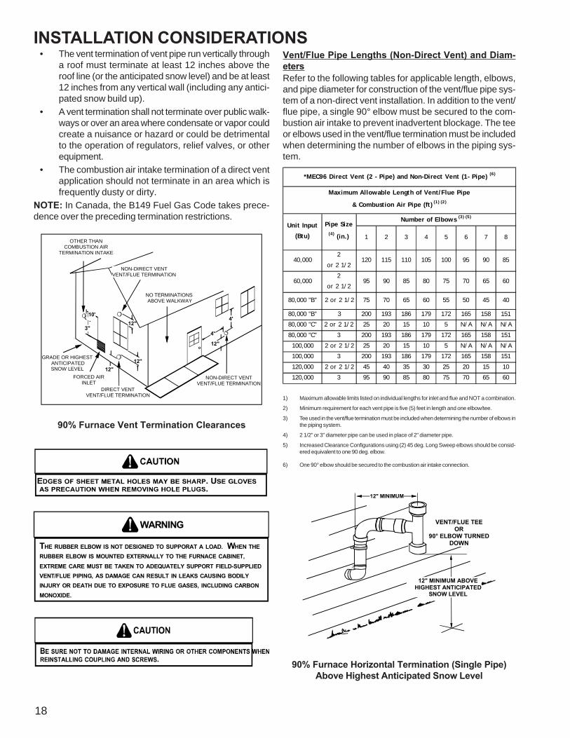
90% Furnace Vent Termination Clearances
WARNING
THE RUBBER ELBOW IS NOT DESIGNED TO SUPPORAT A LOAD. WHEN THERUBBER ELBOW IS MOUNTED EXTERNALLY TO THE FURNACE CABINET,EXTREME CARE MUST BE TAKEN TO ADEQUATELY SUPPORT FIELD-SUPPLIEDVENT/FLUE PIPING, AS DAMAGE CAN RESULT IN LEAKS CAUSING BODILYINJURY OR DEATH DUE TO EXPOSURE TO FLUE GASES, INCLUDING CARBONMONOXIDE.
Vent/Flue Pipe Lengths (Non-Direct Vent) and Diam-etersRefer to the following tables for applicable length, elbows,and pipe diameter for construction of the vent/flue pipe sys-tem of a non-direct vent installation. In addition to the vent/flue pipe, a single 90° elbow must be secured to the com-bustion air intake to prevent inadvertent blockage. The teeor elbows used in the vent/flue termination must be includedwhen determining the number of elbows in the piping sys-tem.
1 2 3 4 5 6 7 8
40,0002
or 2 1/2120 115 110 105 100 95 90 85
60,0002
or 2 1/295 90 85 80 75 70 65 60
80,000 "B" 2 or 2 1/2 75 70 65 60 55 50 45 40
80,000 "B" 3 200 193 186 179 172 165 158 151
80,000 "C" 2 or 2 1/2 25 20 15 10 5 N/A N/A N/A
80,000 "C" 3 200 193 186 179 172 165 158 151
100,000 2 or 2 1/2 25 20 15 10 5 N/A N/A N/A
100,000 3 200 193 186 179 172 165 158 151
120,000 2 or 2 1/2 45 40 35 30 25 20 15 10
120,000 3 95 90 85 80 75 70 65 60
*MEC96 Direct Vent (2 - Pipe) and Non-Direct Vent (1- Pipe) (6)
Maximum Allowable Length of Vent/Flue Pipe
& Combustion Air Pipe (ft) (1) (2)
Unit Input
(Btu)
Pipe Size (4) (in.)
Number of Elbows (3) (5)
1) Maximum allowable limits listed on individual lengths for inlet and flue and NOT a combination.
2) Minimum requirement for each vent pipe is five (5) feet in length and one elbow/tee.
3) Tee used in the vent/flue termination must be included when determining the number of elbows inthe piping system.
4) 2 1/2” or 3” diameter pipe can be used in place of 2” diameter pipe.
5) Increased Clearance Configurations using (2) 45 deg. Long Sweep elbows should be consid-ered equivalent to one 90 deg. elbow.
6) One 90° elbow should be secured to the combustion air intake connection.
12" MINIMUM
VENT/FLUE TEEOR
90° ELBOW TURNEDDOWN
12" MINIMUM ABOVE HIGHEST ANTICIPATED
SNOW LEVEL
90% Furnace Horizontal Termination (Single Pipe)Above Highest Anticipated Snow Level

INSTALLATION CONSIDERATIONS
19
NOTE: Terminate both pipes in the same pressure zone(same side of roof, no major obstacles between pipes,etc.).
COMBUSTION AIR INTAKE(OPTIONAL)*Not required for
single pipe installation
TEE (OPTIONAL)
96” MAX. - 3” MIN.
ROOF LINE
INTAKESCREEN
OPTIONAL
12” MINHEIGHT DIFFERENCE BETWEENINTAKE AND VENT
12” MIN TO ROOF OR HIGHEST ANTICIPATED SNOW LEVEL
STRAIGHT
ELBOWS
VENT/FLUE TEE (or
45° ELBOWTURNED DOWN or
90° ELBOW TURNEDDOWN
OPTIONAL)
12" MIN. ABOVEHIGHEST ANTICIPATED
SNOW LEVEL
12" MIN.
Horizontal Termination (Single Pipe)Above Highest Anticipated Snow Level
90º OR 45°ELBOW
SCREEN(OPTIONAL)
12" MIN. TO GRADE ORHIGHEST ANTICIPATED
SNOW LEVEL
6” MAX
10”- 24”
4” MIN
Standard Horizontal Terminations (Dual Pipe)
SCREEN(OPTIONAL)
AIRINTAKE
90°ELBOWS
12" MIN. ABOVEHIGHEST ANTICIPATED
SNOW LEVEL
3” - 24”
Alternate Horizontal Vent Termination (Dual Pipe)
SCREEN(OPTIONAL)
AIRINTAKE
90°ELBOWS
12" MIN. ABOVEHIGHEST ANTICIPATED
SNOW LEVEL
3”-24” BETWEEN PIPES
Combustion Air Intake may also be snorkeled to obtain 12” min groundclearance.
Alternate Vent Termination Above Anticipated Snow Level(Dual Pipe)

INSTALLATION CONSIDERATIONS
20
VENT/INTAKE TERMINATIONS FOR INSTALLATION OF MUL-TIPLE DIRECT VENT FURNACESIf more than one direct vent furnace is to be installed verti-cally through a common roof top, maintain the same mini-mum clearances between the exhaust vent and air intaketerminations of adjacent units as with the exhaust vent andair intake terminations of a single unit.If more than one direct vent furnace is to be installed hori-zontally through a common side wall, maintain the clear-ances as in the following figure. Always terminate all ex-haust vent outlets at the same elevation and always termi-nate all air intakes at the same elevation.
3” MIN
12” MIN TO GRADE OR HIGHEST ANTICIPATED SNOW LEVEL
12” MIN SEPARATION
3” - 24”
OPTIONALINTAKESCREENS
Termination of Multiple Direct Vent Furnaces
D ire c t V e n tT e rm ina l
5 0 ,0 0 0 B tu ho r le s s
9 "
1 2 "
1 2 " 1 2 "
D ire c t V e n t T e rm in a lM o re th a n 5 0 ,00 0 B tu h
F o rc e d A ir In let
3 '
GR AD E
FIGURE 1
(DCVK) Vent Termination Clearances
1. The vent termination must be located at least 12” aboveground or normally expected snow accumulation levels.
2. Do NOT terminate over public walkways. Avoid areaswhere condensate may cause problems such as aboveplanters, patios, or adjacent to windows where steammay cause fogging.
3. The vent termination shall be located at least 4’horizontally from any electric meter, gas meter,regulator and any relief equipment. These distancesapply ONLY to U.S. Installations.
4. The vent termination shall be located at least 3’ aboveany forced air inlet located within 10’; and at least 10’from a combustion air intake of another appliance,except another direct vent furnace intake.
5. In Canada, the Canadian Fuel Gas Code takesprecedence over the preceding termination instructions.
3" or 4" DiameterSDR-26 Pipe
2 or 2 1/2" DiameterSDR-26 Pipe
2" or 3" DiameterY Concentric Fitting
2" or 3" DiameterRain Cap
These kits are for vertical or horizontal termination of thecombustion air inlet and the exhaust vent pipes on CategoryIV gas-fired condensing furnaces. The DCVK-30 (CVENT-3) kit can be used for 3” diameter pipe systems. The DCVK-20 (CVENT-2) kit can be used for the 2” diameter pipesystem. Both the combustion air inlet and the exhaust ventpipes must attach to the termination kit. The terminationkit must terminate outside the structure and must be installedper the instructions outlined below for vertical or horizontaltermination. Vertical termination is preferred. Field suppliedpipe and fittings are required to complete the installation.
1. Determine the best location for the termination kit. Rooftermination is preferred since it is less susceptible todamage, has reduced intake contaminants and lessvisible vent vapors. For side termination, considerationshould be given to:a. Possible damage from the vapors to plants/shurbs,
other equipment and building materialsb. Possible damage to the terminal from foreign ob-
jectsc. Wind effects that may cause recirculation of flue
products, debris or light snowd. Visible vent vapors.

INSTALLATION CONSIDERATIONS
21
Vent
Maintain 12" (18" for Canada) minimum clearance above highest anticipated snow level. Maximum of 24" above roof.Combustion Air
Roof Boot/Flashing(Field Supplied)
Support (Field Supplied)
45 Elbow(Field Supplied)
Combustion AirVent
Condensate Drain Lines and Drain Trap
A condensing gas furnace achieves its high level of efficiencyby extracting almost all of the heat from the products ofcombustion and cooling them to the point where condensa-tion takes place. The condensate which is generated mustbe piped to an appropriate drain location.
WARNING
IN UPRIGHT UPFLOW INSTALLATIONS, THE DRAIN TRAP MUST BE MOUNTED ONTHE OPPOSITE SIDE OF THE UNIT FROM THE JUNCTION BOX. THIS WILL REDUCE THE RISK OF WATER REACHING THE JUNCTION BOX IN THE EVENT OFA BLOCKED DRAIN CONDITION. FAILURE TO FOLLOW THESE INSTRUCTIONSCAN RESULT IN POSSIBLE PROPERTY DAMAGE, PERSONAL INJURY, OR DEATHDUE TO ELECTRICAL SHOCK.
• If the drain line is routed through an area which maysee temperatures near or below freezing, precau-tions must be taken to prevent condensate fromfreezing within the drain line.
• If an air conditioning coil is installed with thefurnace, a common drain may be used. An opentee must be installed in the drain line, near thecooling coil, to relieve positive air pressure from thecoil’s plenum. This is necessary to prohibit anyinterference with the function of the furnace’s draintrap.
GAS SUPPLY AND PIPINGThe furnace rating plate includes the approved furnace gasinput rating and gas types. The furnace must be equipped tooperate on the type of gas applied. This includes any con-version kits required for alternate fuels and/or high altitude.
CAUTION
TO PREVENT UNRELIABLE OPERATION OR EQUIPMENT DAMAGE, THE INLETGAS SUPPLY PRESSURE MUST BE AS SPECIFIED ON THE UNIT RATING PLATEWITH ALL OTHER HOUSEHOLD GAS FIRED APPLIANCES OPERATING.
Inlet gas supply pressures must be maintained within theranges specified below. The supply pressure must be con-stant and available with all other household gas fired appli-ances operating. The minimum gas supply pressure mustbe maintained to prevent unreliable ignition. The maximummust not be exceeded to prevent unit overfiring.
Natural Gas Minimum: 4.5" w.c. Maximum: 10.0" w.c.Propane Gas Minimum: 11.0" w.c. Maximum: 13.0" w.c.
INLET GAS SUPPLY PRESSURE
HIGH ALTITUDE DERATEWhen this furnace is installed at high altitude, the appropri-ate High Altitude orifice kit must be applied. This is re-quired due to the natural reduction in the density of boththe gas fuel and combustion air as altitude increases. Thekit will provide the proper design certified input rate withinthe specified altitude range.High altitude kits are purchased according to the installa-tion altitude and usage of either natural or propane gas.Refer to the product Specification Sheet or Technical Manualfor a tabular listing of appropriate altitude ranges and corre-sponding manufacturer’s high altitude (Natural, Propane gas,and/or Pressure Switch) kits.Do not derate the furnace by adjusting the manifold pres-sure to a lower pressure than specified on the furnace rat-ing plate. The combination of the lower air density and alower manifold pressure will prohibit the burner orifice fromdrawing the proper amount of air into the burner. This maycause incomplete combustion, flashback, and possible yel-low tipping.In some areas the gas supplier may artificially derate thegas in an effort to compensate for the effects of altitude. Ifthe gas is artificially derated, the appropriate orifice sizemust be determined based upon the BTU/ft3 content of thederated gas and the altitude. Refer to the National FuelGas Code, NFPA 54/ANSI Z223.1, and information providedby the gas supplier to determine the proper orifice size.A different pressure switch may be required at high altituderegardless of the BTU/ft3 content of the fuel used. Refer tothe product Specification Sheet or Technical Manual for atabular listing of appropriate altitude ranges and correspond-ing manufacturer’s pressure switch kits.
INSTALLATION CONSIDERATIONS
22
PROPANE GAS CONVERSION
WARNING
POSSIBLE PROPERTY DAMAGE, PERSONAL INJURY OR DEATH MAY OCCUR IFTHE CORRECT CONVERSION KITS ARE NOT INSTALLED. THE APPROPRIATE KITSMUST BE APPLIED TO INSURE SAFE AND PROPER FURNACE OPERATION. ALLCONVERSIONS MUST BE PERFORMED BY A QUALIFIED INSTALLER OR SERVICEAGENCY.
This unit is configured for natural gas. The appropriatemanufacturer’s propane gas conversion kit, must be appliedfor propane gas installations.Refer to the specification sheet for the model you are servic-ing. Refer to the “propane gas and/or High Altitude Installa-tions” section for details.
GAS VALVEThis unit is equipped with a 24 volt gas valve controlled dur-ing furnace operation by the integrated control module. Asshipped, the valve is configured for natural gas. The valve isfield convertible for use with propane gas by using the ap-propriate propane gas conversion kit. Taps for measuringthe gas supply pressure and manifold pressure are providedon the valve.NOTE: The gas supply pressure on White-Rodgers "G/J"model gas valve, can be checked with a gas pressure testkit (Part #0151K00000S) available through our authorizeddistributors.
The gas valve has a manual ON/OFF control located on thevalve itself. This control may be set only to the “ON” or “OFF”position. Refer to the Lighting Instructions Label or the “Put-ting the Furnace Into Operation” section of this manual orthe installation instructions for use of this control during startup and shut down periods.
GAS PIPING CONNECTIONS
CAUTION
TO AVOID POSSIBLE UNSATISFACTORY OPERATION OR EQUIPMENT DAMAGEDUE TO UNDERFIRING OF EQUIPMENT, USE THE PROPER SIZE OFNATURAL/PROPANE GAS PIPING NEEDED WHEN RUNNING PIPE FROM THEMETER/TANK TO THE FURNACE.
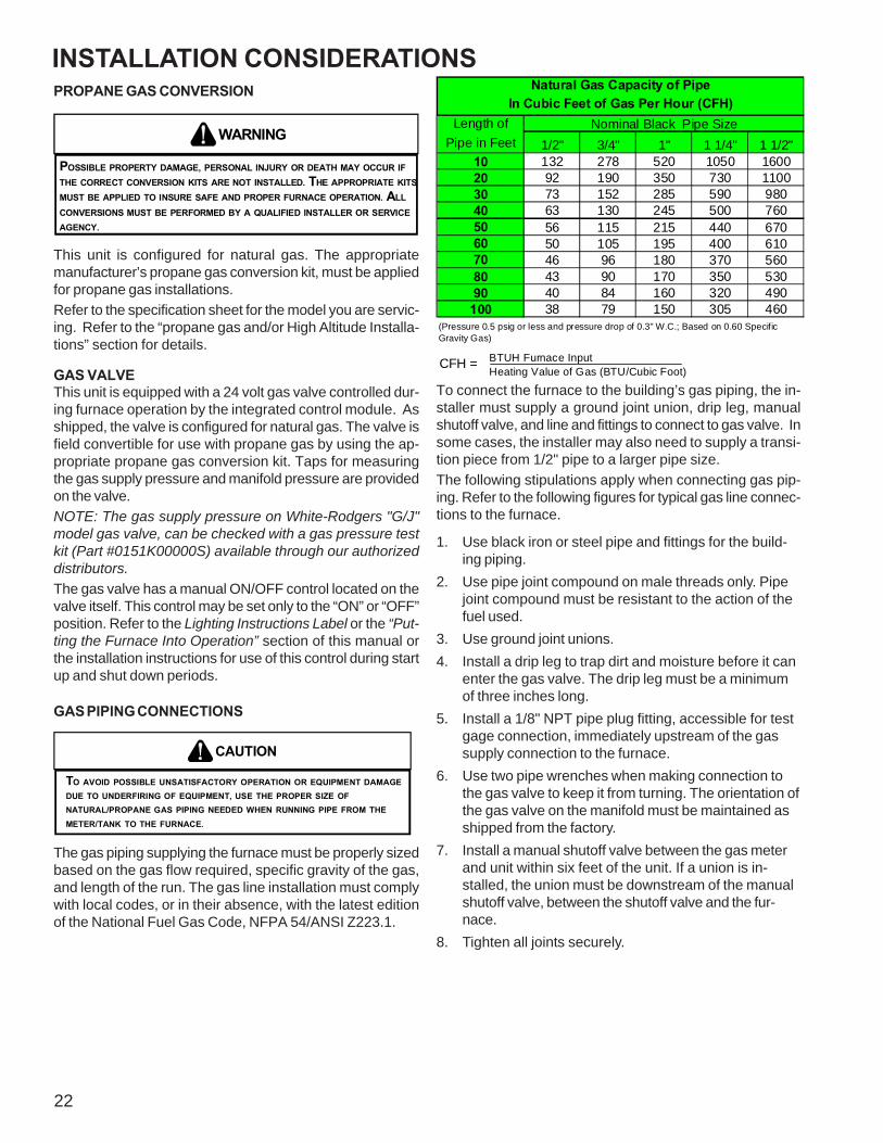
The gas piping supplying the furnace must be properly sizedbased on the gas flow required, specific gravity of the gas,and length of the run. The gas line installation must complywith local codes, or in their absence, with the latest editionof the National Fuel Gas Code, NFPA 54/ANSI Z223.1.
Length of Nominal Black Pipe SizePipe in Feet 1/2" 3/4" 1" 1 1/4" 1 1/2"
10 132 278 520 1050 160020 92 190 350 730 110030 73 152 285 590 98040 63 130 245 500 76050 56 115 215 440 67060 50 105 195 400 61070 46 96 180 370 56080 43 90 170 350 53090 40 84 160 320 490
100 38 79 150 305 460
CFH =
(Pressure 0.5 psig or less and pressure drop of 0.3" W.C.; Based on 0.60 Specific Gravity Gas)
Natural Gas Capacity of PipeIn Cubic Feet of Gas Per Hour (CFH)
BTUH Furnace Input Heating Value of Gas (BTU/Cubic Foot)
To connect the furnace to the building’s gas piping, the in-staller must supply a ground joint union, drip leg, manualshutoff valve, and line and fittings to connect to gas valve. Insome cases, the installer may also need to supply a transi-tion piece from 1/2" pipe to a larger pipe size.The following stipulations apply when connecting gas pip-ing. Refer to the following figures for typical gas line connec-tions to the furnace.
1. Use black iron or steel pipe and fittings for the build-ing piping.
2. Use pipe joint compound on male threads only. Pipejoint compound must be resistant to the action of thefuel used.
3. Use ground joint unions.4. Install a drip leg to trap dirt and moisture before it can
enter the gas valve. The drip leg must be a minimumof three inches long.
5. Install a 1/8" NPT pipe plug fitting, accessible for testgage connection, immediately upstream of the gassupply connection to the furnace.
6. Use two pipe wrenches when making connection tothe gas valve to keep it from turning. The orientation ofthe gas valve on the manifold must be maintained asshipped from the factory.
7. Install a manual shutoff valve between the gas meterand unit within six feet of the unit. If a union is in-stalled, the union must be downstream of the manualshutoff valve, between the shutoff valve and the fur-nace.
8. Tighten all joints securely.

INSTALLATION CONSIDERATIONS
23
GAS PIPING CHECKSBefore placing unit in operation, leak test the unit and gasconnections.
WARNING
TO AVOID THE POSSIBLITY OF EXPLOSION OR FIRE, NEVER USE A MATCHOR OPEN FLAME TO TEST FOR LEAKS.
Check for leaks using an approved chloride-free soap andwater solution, an electronic combustible gas detector, orother approved testing methods.NOTE: Never exceed specified pressures for testing. Higherpressure may damage the gas valve and cause subsequentoverfiring, resulting in heat exchanger failure. Disconnect thisunit and shutoff valve from the gas supply piping systembefore pressure testing the supply piping system with pres-sures in excess of 1/2 psig (3.48 kPa). Isolate this unit fromthe gas supply piping system by closing its external manualgas shutoff valve before pressure testing supply piping sys-tem with test pressures equal to or less than 1/2 psig (3.48kPa).
PROPANE GAS TANKS AND PIPING
WARNING
PROPANE GAS IS HEAVIER THAN AIR AND ANY LEAKING GAS CAN SETTLE INANY LOW AREAS OR CONFINED SPACES. TO PREVENT PROPERTY DAMAGE,PERSONAL INJURY, OR DEATH DUE TO FIRE OR EXPLOSION CAUSED BY APROPANE GAS LEAK, INSTALL A GAS DETECTION WARNING DEVICE.
A gas detecting warning system is the only reliable way todetect a propane gas leak. Iron oxide (rust) can reduce thelevel of odorant in propane gas. Do not rely on your sense ofsmell. Contact a local propane gas supplier about installinga gas detecting warning system. If the presence of gas issuspected, please refer to the warning on this page.All propane gas equipment must conform to the safety stan-dards of the National Board of Fire Underwriters, NBFUManual 58.For satisfactory operation, propane gas pressure must be10 inch WC at the furnace manifold with all gas appliancesin operation. Maintaining proper gas pressure depends onthree main factors:1. Vaporization rate, depending on temperature of the liq-
uid, and “wetted surface” area of the container or con-tainers.
2. Proper pressure regulation. (Two-stage regulation is rec-ommended for both cost and efficiency).
3. Pressure drop in lines between regulators, and betweensecond stage regulator and the appliance. Pipe size willdepend on length of pipe run and total load of all appli-ances.
Complete information regarding tank sizing for vaporization,recommended regulator settings, and pipe sizing is avail-able from most regulator manufacturers and propane gassuppliers.Refer to the following illustration for typical propane gas in-stallations and piping.
200 PSIGMaximum
5 to 15 PSIG(20 PSIG Max.) Continuous
11" W.C.
Second StageRegulator
First StageRegulator
Typical Propane Gas Installation
WARNING
IF THE GAS FURNACE IS INSTALLED IN A BASEMENT, AN EXCAVATEDAREA OR A CONFINED SPACE, IT IS STRONGLY RECOMMENDED TOCONTACT A PROPANE SUPPLIER TO INSTALL A GAS DETECTINGWARNING DEVICE IN CASE OF A GAS LEAK.
• SINCE PROPANE GAS IS HEAVIER THAN AIR, ANY LEAKING GAS CAN SETTLE IN ANY LOW AREAS OR CONFINED SPACES. • PROPANE GAS ODORANT MAY FADE, MAKING THE GAS UNDETECTABLE EXCEPT WITH A WARNING DEVICE.
WARNING
AN UNDETECTED GAS LEAK WILL CREATE A DANGER OF EXPLOSIONOR FIRE. IF THE PRESENCE OF GAS IS SUSPECTED, FOLLOW THEINSTRUCTIONS ON THE COVER OF THIS MANUAL. FAILURE TO DO SOCOULD RESULT IN SERIOUS PERSONAL INJURY OR DEATH.
INSTALLATION CONSIDERATIONS
24
WARNING
IF THE INFORMATION IN THESE INSTRUCTIONS IS NOT FOLLOWED EXACTLY, AFIRE OR EXPLOSION MAY RESULT CAUSING PROPERTY DAMAGE, PERSONALINJURY OR LOSS OF LIFE.
– DO NOT STORE OR USE GASOLINE OR OTHER FLAMMABLE VAPORS AND
LIQUIDS IN THE VICINITY OF THIS OR ANY OTHER APPLIANCE.
– WHAT TO DO IF YOU SMELL GAS:
• DO NOT TRY TO LIGHT ANY APPLIANCE.
• DO NOT TOUCH ANY ELECTRICAL SWITCH; DO NOT USE ANY
PHONE IN YOUR BUILDING.
• IMMEDIATELY CALL YOUR GAS SUPPLIER FROM A NEIGHBOR’S
PHONE. FOLLOW THE GAS SUPPLIER’S INSTRUCTIONS.
• IF YOU CANNOT REACH YOUR GAS SUPPLIER, CALL THE FIRE
DEPARTMENT.– INSTALLATION AND SERVICE MUST BE PERFORMED BY A QUALIFIED INSTALLER,
SERVICE AGENCY OR THE GAS SUPPLIER.
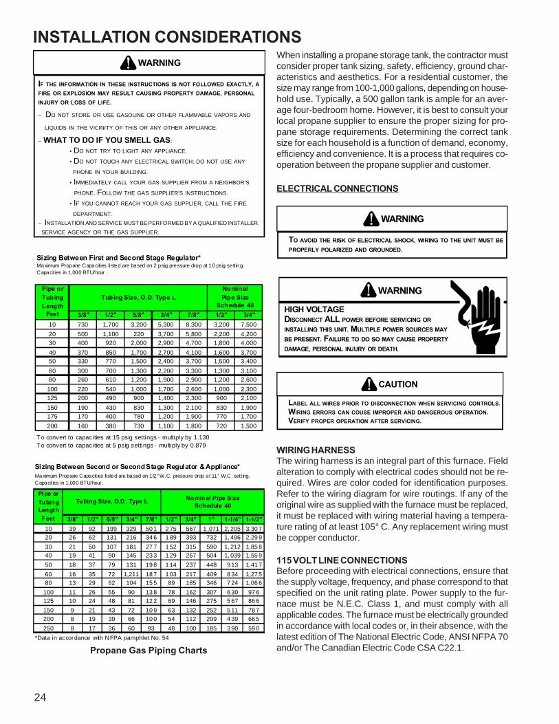
3/8" 1/2" 5/8" 3/4" 7/8" 1/2" 3/4"10 730 1,700 3,200 5,300 8,300 3,200 7,50020 500 1,100 220 3,700 5,800 2,200 4,20030 400 920 2,000 2,900 4,700 1,800 4,00040 370 850 1,700 2,700 4,100 1,600 3,70050 330 770 1,500 2,400 3,700 1,500 3,40060 300 700 1,300 2,200 3,300 1,300 3,10080 260 610 1,200 1,900 2,900 1,200 2,600
100 220 540 1,000 1,700 2,600 1,000 2,300125 200 490 900 1,400 2,300 900 2,100150 190 430 830 1,300 2,100 830 1,900175 170 400 780 1,200 1,900 770 1,700200 160 380 730 1,100 1,800 720 1,500
Pipe orTubingLength
Feet
Tubing Size, O.D. Type LNominalPipe Size
Schedule 40
Sizing Between First and Second Stage Regulator*Maximum Propane Capacities listed are based on 2 psig pressure drop at 10 psig setting.Capacities in 1,000 BTU/hour .
To convert to capacities at 15 psig settings - multiply by 1.130To convert to capacities at 5 psig settings - multiply by 0.879
3/8" 1/2" 5/8" 3/4" 7/8" 1/2" 3/4" 1" 1-1/4" 1-1/2"10 39 92 199 329 50 1 2 75 567 1 ,071 2, 205 3,30 720 26 62 131 216 34 6 1 89 393 732 1, 496 2,29 930 21 50 107 181 27 7 1 52 315 590 1, 212 1,85 840 19 41 90 145 23 3 1 29 267 504 1, 039 1,55 950 18 37 79 131 19 8 1 14 237 448 9 13 1,41 760 16 35 72 1,211 18 7 1 03 217 409 8 34 1,27 580 13 29 62 104 15 5 89 185 346 7 24 1,06 6
100 11 26 55 90 13 8 78 162 307 6 30 97 6125 10 24 48 81 12 2 69 146 275 5 67 86 6150 9 21 43 72 10 9 63 132 252 5 11 78 7200 8 19 39 66 10 0 54 112 209 4 39 66 5250 8 17 36 60 93 48 100 185 3 90 59 0
Tubing Size, O.D . Type L Nominal Pipe SizeSchedule 40
Pi pe orTubingLength
Feet
*Data in accordance with NFPA pamphlet No. 54
Sizing Between Second or Second Stage Regulator & Appliance*Maximum Propane Capacities listed are based on 1 /2" W.C. pressure drop at 11" W.C. setting.Capacities in 1,000 BTU/hour .
Propane Gas Piping Charts
When installing a propane storage tank, the contractor mustconsider proper tank sizing, safety, efficiency, ground char-acteristics and aesthetics. For a residential customer, thesize may range from 100-1,000 gallons, depending on house-hold use. Typically, a 500 gallon tank is ample for an aver-age four-bedroom home. However, it is best to consult yourlocal propane supplier to ensure the proper sizing for pro-pane storage requirements. Determining the correct tanksize for each household is a function of demand, economy,efficiency and convenience. It is a process that requires co-operation between the propane supplier and customer.
ELECTRICAL CONNECTIONS
WARNING
TO AVOID THE RISK OF ELECTRICAL SHOCK, WIRING TO THE UNIT MUST BEPROPERLY POLARIZED AND GROUNDED.
WARNING
HIGH VOLTAGEDISCONNECT ALL POWER BEFORE SERVICING ORINSTALLING THIS UNIT. MULTIPLE POWER SOURCES MAYBE PRESENT. FAILURE TO DO SO MAY CAUSE PROPERTYDAMAGE, PERSONAL INJURY OR DEATH.
CAUTION
LABEL ALL WIRES PRIOR TO DISCONNECTION WHEN SERVICING CONTROLS.WIRING ERRORS CAN COUSE IMPROPER AND DANGEROUS OPERATION.VERIFY PROPER OPERATION AFTER SERVICING.
WIRING HARNESSThe wiring harness is an integral part of this furnace. Fieldalteration to comply with electrical codes should not be re-quired. Wires are color coded for identification purposes.Refer to the wiring diagram for wire routings. If any of theoriginal wire as supplied with the furnace must be replaced,it must be replaced with wiring material having a tempera-ture rating of at least 105° C. Any replacement wiring mustbe copper conductor.
115 VOLT LINE CONNECTIONSBefore proceeding with electrical connections, ensure thatthe supply voltage, frequency, and phase correspond to thatspecified on the unit rating plate. Power supply to the fur-nace must be N.E.C. Class 1, and must comply with allapplicable codes. The furnace must be electrically groundedin accordance with local codes or, in their absence, with thelatest edition of The National Electric Code, ANSI NFPA 70and/or The Canadian Electric Code CSA C22.1.

INSTALLATION CONSIDERATIONS
25
Use a separate fused branch electrical circuit containingproperly sized wire, and fuse or circuit breaker. The fuse orcircuit breaker must be sized in accordance with the maxi-mum overcurrent protection specified on the unit rating plate.An electrical disconnect must be provided at the furnacelocation.NOTE: Line polarity must be observed when making fieldconnections.
WARNING
IN 90% FURNACE UPRIGHT UPFLOW INSTALLATIONS, THE DRAIN TRAP MUSTBE MOUNTED ON THE OPPOSITE SIDE OF THE UNIT FROM THE JUNCTIONBOX. THIS WILL REDUCE THE RISK OF WATER REACHING THE JUNCTIONBOX IN THE EVENT OF A BLOCKED DRAIN CONDITION.
Connect hot, neutral, and ground wires as shown in the wir-ing diagram located on the unit’s blower door. Line polaritymust be observed when making field connections. Line volt-age connections can be made through either the right or leftside panel.
NOTE: Wire routing must not interfere with circulatorblower operation, filter removal, or routine maintenance.
WARNING
TO AVOID THE RISK OF ELECTRICAL SHOCK, INJURY, OR DEATH, THEFURNACE MUST BE ELECTRICALLY GROUNDED IN ACCORDANCE WITH LOCALCODES OR, IN THEIR ABSENCE, WITH THE LATEST EDITION OF THE NATIONAL ELECTRIC CODE.
115 VOLT LINE CONNECTION OF ACCESSORIES(ELECTRONIC AIR CLEANER)
WARNING
HIGH VOLTAGEDISCONNECT ALL POWER BEFORE SERVICING ORCHANGING ANY ELECTRICAL WIRING. MULTIPLE POWERSOURCES MAY BE PRESENT. FAILURE TO DO SO MAY CAUSEPROPERTY DAMAGE, PERSONAL INJURY OR DEATH.
ElectronicAir Cleaner
1.0 Amp maximum at 120 VAC
Humidifier 1.0 Amp maximum at 120 VAC
ACCESSORY LOAD SPECIFICATIONS
Turn OFF power to the furnace before installing any acces-sories. Follow the humidifier or air cleaner manufacturers’instructions for locating, mounting, grounding, and control-ling these accessories.If it is necessary for the installer to supply additional linevoltage wiring to the inside of the furnace, the wiring mustconform to all local codes, and have a minimum tempera-ture rating of 105°C. All line voltage wire splices must bemade inside the furnace junction box.The integrated control module electronic air cleaner termi-nals (EAC) are energized with 115 volts whenever the circu-lator blower is energized.
24 VOLT THERMOSTAT WIRINGNOTE: Low voltage connections can be made through ei-ther the right or left side panel. Wire routing must not inter-fere with circulator blower operation, filter removal, or routinemaintenance.A 40 V.A. transformer and an integrated electronic controlare built into the furnace to allow use with most cooling equip-ment. Consult the wiring diagram, located in the TechnicalManual or on the blower door for further details of 115 Voltand 24 Volt wiring.
THERMOSTAT WIRINGThe *MEC96 furnace has W1 & W2 terminals for connec-tion of a two stage heating thermostat. If desired, a thermo-stat with only one stage of heat may be used. As shipped,the furnace S1-1 switch is OFF; S1-2 switch is ON. This isthe correct position to use a single stage heating thermo-stat with auto timing transition to high fire.
R
Y C
Furnace Integrated
Control Module
Remote Condensing Unit(Single-Stage Cooling)
R
Thermostat - Single -Stage Heating with Single-Stage CoolingNOTE: To apply a single-stage Heating Thermostat, thethermostat selector switch on the Integrated Control Modulemust be set on single-stage.
R
Y C
Furnace Integrated
Control Module
Remote Condensing Unit(Single-Stage Cooling)
R
Thermostat - Two-Stage Heating with Single-Stage Cooling
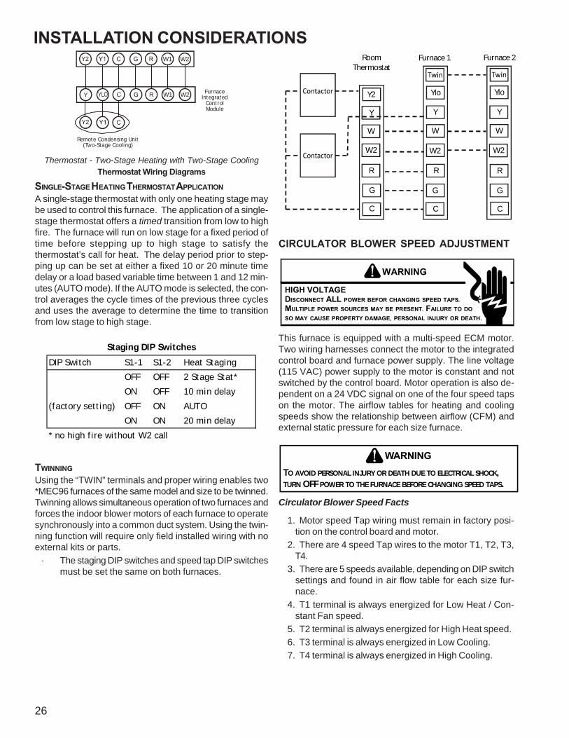
INSTALLATION CONSIDERATIONS
26
W1 W2Y Furnace Integrated
Control Module
Remote Condensing Unit(Two-Stage Cooling)
Y2
W1 W2Y2
Thermostat - Two-Stage Heating with Two-Stage CoolingThermostat Wiring Diagrams
SINGLE-STAGE HEATING THERMOSTAT APPLICATIONA single-stage thermostat with only one heating stage maybe used to control this furnace. The application of a single-stage thermostat offers a timed transition from low to highfire. The furnace will run on low stage for a fixed period oftime before stepping up to high stage to satisfy thethermostat’s call for heat. The delay period prior to step-ping up can be set at either a fixed 10 or 20 minute timedelay or a load based variable time between 1 and 12 min-utes (AUTO mode). If the AUTO mode is selected, the con-trol averages the cycle times of the previous three cyclesand uses the average to determine the time to transitionfrom low stage to high stage.
DIP Switch S1-1 S1-2 Heat Staging
OFF OFF 2 Stage Stat*
ON OFF 10 min delay
(factory setting) OFF ON AUTO
ON ON 20 min delay
* no high fire without W2 call
Staging DIP Switches
TWINNINGUsing the “TWIN” terminals and proper wiring enables two*MEC96 furnaces of the same model and size to be twinned.Twinning allows simultaneous operation of two furnaces andforces the indoor blower motors of each furnace to operatesynchronously into a common duct system. Using the twin-ning function will require only field installed wiring with noexternal kits or parts.
· The staging DIP switches and speed tap DIP switchesmust be set the same on both furnaces.
RoomThermostat
Y2
Y
W
W2
R
G
C
Ylo
Y
W
W2
R
G
C
Ylo
Y
W
W2
R
G
C
Furnace 1 Furnace 2
CIRCULATOR BLOWER SPEED ADJUSTMENT
WARNING
HIGH VOLTAGEDISCONNECT ALL POWER BEFOR CHANGING SPEED TAPS.MULTIPLE POWER SOURCES MAY BE PRESENT. FAILURE TO DOSO MAY CAUSE PROPERTY DAMAGE, PERSONAL INJURY OR DEATH.
This furnace is equipped with a multi-speed ECM motor.Two wiring harnesses connect the motor to the integratedcontrol board and furnace power supply. The line voltage(115 VAC) power supply to the motor is constant and notswitched by the control board. Motor operation is also de-pendent on a 24 VDC signal on one of the four speed tapson the motor. The airflow tables for heating and coolingspeeds show the relationship between airflow (CFM) andexternal static pressure for each size furnace.
TO AVOID PERSONAL INJURY OR DEATH DUE TO ELECTRICAL SHOCK, TURN OFF POWER TO THE FURNACE BEFORE CHANGING SPEED TAPS.
WARNING
Circulator Blower Speed Facts
1. Motor speed Tap wiring must remain in factory posi-tion on the control board and motor.
2. There are 4 speed Tap wires to the motor T1, T2, T3,T4.
3. There are 5 speeds available, depending on DIP switchsettings and found in air flow table for each size fur-nace.
4. T1 terminal is always energized for Low Heat / Con-stant Fan speed.
5. T2 terminal is always energized for High Heat speed. 6. T3 terminal is always energized in Low Cooling. 7. T4 terminal is always energized in High Cooling.

SYSTEM OPERATION
27
8. Heating input (W1/ W2) always has priority over allother thermostat input.
9. Cooling input (YLo/ Y) has priority over continuous faninput.
10. Continuous fan input (G) has lowest priority.*The blower speed wiring connections must remain infactory position.
1. Refer to the air flow table for your specific modelfurnace2. If a cooling or heat pump condensing unit is being
used in conjunction with this furnace, the three DIPswitches in S2 are used to select the propercooling speeds to match the outdoor unit size. TypicalCFM requirements are 400 CFM / Ton.
1. Turn OFF power to the furnace.2. Select the heating and cooling blower speeds that match
the installation requirements from the airflow table inthis manual or the Service Manual, If factory coolingspeeds do not match the installation requirements, thedip switch settings must be changed from factory posi-tion
3. Turn ON power to furnace.4. Verify proper temperature rise in heat modes and CFM
in cooling modesIn general lower heating speeds will: reduce electrical consump-tion, lower operating sound levels of the blower, and increasethe outlet air temperature delivered to the home. The speedsavailable allow the blower performance to be optimized for theparticular homeowner’s needs.
CIRCULATING AIR AND FILTERSDUCTWORK - AIR FLOWDuct systems and register sizes must be properly designedfor the C.F.M. and external static pressure rating of thefurnace. Ductwork should be designed in accordance withthe recommended methods of "Air Conditioning Contrac-tors of America" manual D.A duct system should be installed in accordance with Stan-dards of the National Board of Fire Underwriters for the In-stallation of Air Conditioning, Warm Air Heating and Venti-lating Systems, Pamphlets No. 90A and 90B.A return air filter is not supplied with the furnace. The in-staller must supply a means of filtering all of the return air.Filter(s) shall comply with UL900 or CAN/ULC-S111 Stan-dards. If the furnace is installed without filters, the warrantywill be voided.Upflow furnaces with air delivery of less than 1800 CFM:
Use one side return or one bottom return ductwork connec-tion.
Upflow furnaces with air delivery of 1800 CFM or higher:
Use two side returns or one side return and one bottomreturn connection.Guide dimples locate the side and bottom return cutout lo-cations. Use a straight edge to scribe lines connecting thedimples. Cut out the opening on these lines. An undersizedopening will cause reduced airflow. For bottom return con-nection, remove the bottom of the cabinet before setting thefurnace on the raised platform or return air duct.A closed return duct system must be used, with the returnduct connected to the furnace. NOTE: Ductwork must neverbe attached to the back of the furnace. Supply and returnconnections to the furnace may be made with flexible jointsto reduce noise transmission, if desired. If a central returnis used, a connecting duct must be installed between theunit and the utility room wall so the blower will not interferewith combustion air or draft. The room, closet, or alcovemust not be used as a return air chamber.When the furnace is used in connection with a cooling unit,the furnace should be installed in parallel with or on theupstream side of the cooling unit to avoid condensation inthe heating element. With a parallel flow arrangement, thedampers or other means used to control the flow of air mustbe adequate to prevent chilled air from entering the furnaceand, if manually operated, must be equipped with means toprevent operation of either unit unless the damper is in thefull heat or cool position.When the furnace is heating, the temperature of the returnair entering the furnace must be between 55°F and 100°F.
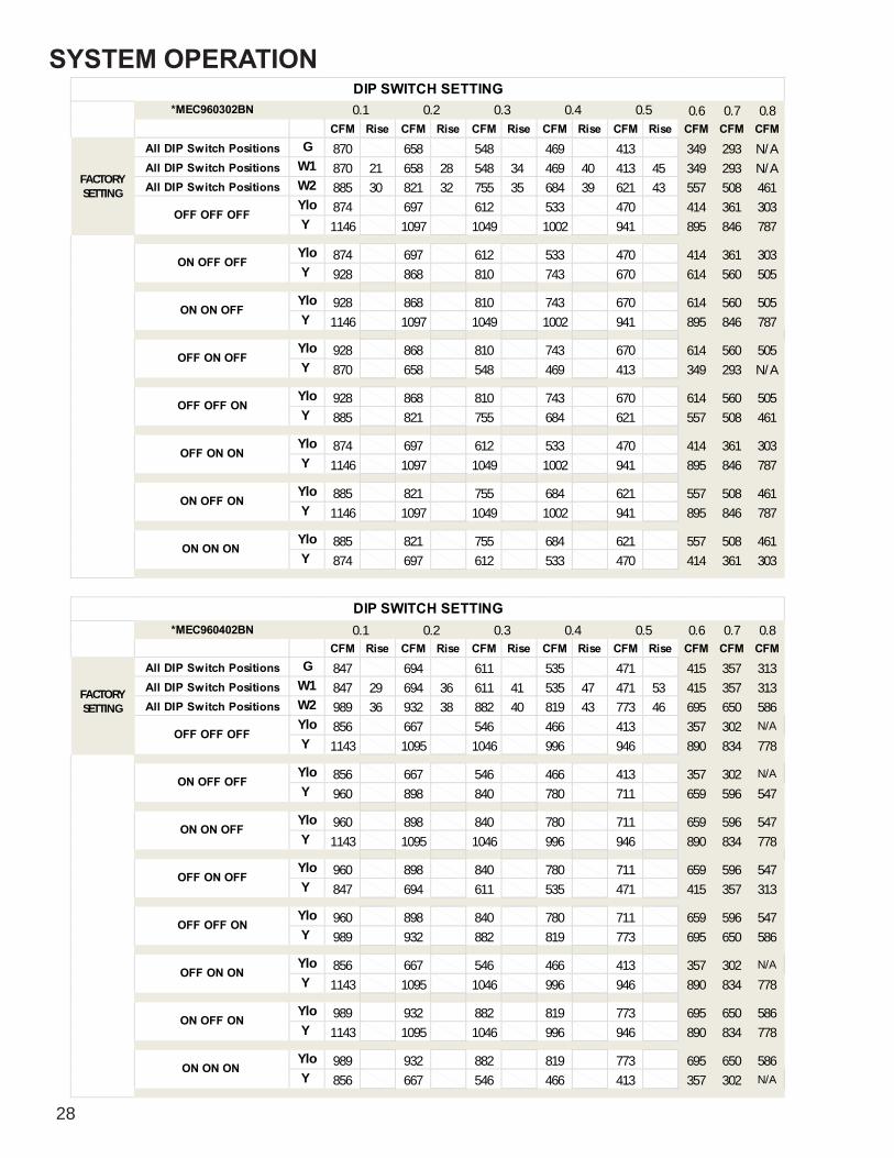
SYSTEM OPERATION
28
*MEC960302BN 0.6 0.7 0.8CFM Rise CFM Rise CFM Rise CFM Rise CFM Rise CFM CFM CFM
All DIP Switch Positions G 870 658 548 469 413 349 293 N/AAll DIP Switch Positions W1 870 21 658 28 548 34 469 40 413 45 349 293 N/AAll DIP Switch Positions W2 885 30 821 32 755 35 684 39 621 43 557 508 461
Ylo 874 697 612 533 470 414 361 303Y 1146 1097 1049 1002 941 895 846 787
Ylo 874 697 612 533 470 414 361 303Y 928 868 810 743 670 614 560 505
Ylo 928 868 810 743 670 614 560 505Y 1146 1097 1049 1002 941 895 846 787
Ylo 928 868 810 743 670 614 560 505Y 870 658 548 469 413 349 293 N/A
Ylo 928 868 810 743 670 614 560 505Y 885 821 755 684 621 557 508 461
Ylo 874 697 612 533 470 414 361 303Y 1146 1097 1049 1002 941 895 846 787
Ylo 885 821 755 684 621 557 508 461Y 1146 1097 1049 1002 941 895 846 787
Ylo 885 821 755 684 621 557 508 461Y 874 697 612 533 470 414 361 303
DIP SWITCH SETTING0.50.1 0.2 0.3 0.4
OFF ON ON
ON OFF ON
ON ON ON
OFF OFF OFF
ON OFF OFF
ON ON OFF
OFF ON OFF
OFF OFF ON
FACTORYSETTING
*MEC960402BN 0.6 0.7 0.8CFM Rise CFM Rise CFM Rise CFM Rise CFM Rise CFM CFM CFM
All DIP Switch Positions G 847 694 611 535 471 415 357 313All DIP Switch Positions W1 847 29 694 36 611 41 535 47 471 53 415 357 313All DIP Switch Positions W2 989 36 932 38 882 40 819 43 773 46 695 650 586
Ylo 856 667 546 466 413 357 302 N/AY 1143 1095 1046 996 946 890 834 778
Ylo 856 667 546 466 413 357 302 N/AY 960 898 840 780 711 659 596 547
Ylo 960 898 840 780 711 659 596 547Y 1143 1095 1046 996 946 890 834 778
Ylo 960 898 840 780 711 659 596 547Y 847 694 611 535 471 415 357 313
Ylo 960 898 840 780 711 659 596 547Y 989 932 882 819 773 695 650 586
Ylo 856 667 546 466 413 357 302 N/AY 1143 1095 1046 996 946 890 834 778
Ylo 989 932 882 819 773 695 650 586Y 1143 1095 1046 996 946 890 834 778
Ylo 989 932 882 819 773 695 650 586Y 856 667 546 466 413 357 302 N/A
0.3 0.4 0.5
DIP SWITCH SETTING0.1 0.2
OFF OFF ON
OFF ON ON
ON OFF ON
ON ON ON
OFF OFF OFF
ON OFF OFF
ON ON OFF
OFF ON OFF
FACTORYSETTING

SYSTEM OPERATION
29
*MEC960603BN 0.6 0.7 0.8CFM Rise CFM Rise CFM Rise CFM Rise CFM Rise CFM CFM CFM
All DIP Switch Positions G 894 846 780 720 660 603 554 505All DIP Switch Positions W1 894 42 846 44 780 48 720 52 660 57 603 554 505All DIP Switch Positions W2 1328 40 1287 41 1249 43 1215 44 1170 46 1131 1085 1046
Ylo 782 629 547 469 396 333 N/A N/AY 1236 1189 1149 1101 1066 1017 969 928
Ylo 782 629 547 469 396 333 N/A N/AY 1149 1104 1057 1017 963 918 865 822
Ylo 1149 1104 1057 1017 963 918 865 822Y 1236 1189 1149 1101 1066 1017 969 928
Ylo 1149 1104 1057 1017 963 918 865 822Y 894 846 780 720 660 603 554 505
Ylo 1149 1104 1057 1017 963 918 865 822Y 1328 1287 1249 1215 1170 1131 1085 1046
Ylo 782 629 547 469 396 333 N/A N/AY 1236 1189 1149 1101 1066 1017 969 928
Ylo 1328 1287 1249 1215 1170 1131 1085 1046Y 1236 1189 1149 1101 1066 1017 969 928
Ylo 1328 1287 1249 1215 1170 1131 1085 1046Y 782 629 547 469 396 333 N/A N/A
0.4
DIP SWITCH SETTING
OFF OFF ON
OFF ON ON
0.5
OFF OFF OFF
ON OFF OFF
ON ON OFF
OFF ON OFF
0.1 0.2
ON OFF ON
ON ON ON
0.3
FACTORYSETTING
*MEC960803BN 0.6 0.7 0.8CFM Rise CFM Rise CFM Rise CFM Rise CFM Rise CFM CFM CFM
All DIP Switch Positions G 1221 1172 1128 1087 1049 1005 959 922All DIP Switch Positions W1 1221 41 1172 42 1128 44 1087 46 1049 47 1005 959 922All DIP Switch Positions W2 1311 54 1293 55 1249 57 1203 59 1172 61 1122 1088 1041
Ylo 750 644 569 507 442 388 328 N/AY 1111 1068 1025 984 941 885 N/A 801
Ylo 750 644 569 507 442 388 328 N/AY 894 842 784 726 682 618 562 519
Ylo 894 842 784 726 682 618 562 519Y 1111 1068 1025 984 941 885 N/A 801
Ylo 894 842 784 726 682 618 562 519Y 1221 1172 1128 1087 1049 1005 959 922
Ylo 894 842 784 726 682 618 562 519Y 1311 1293 1249 1203 1172 1122 1088 1041
Ylo 750 644 569 507 442 388 328 N/AY 1111 1068 1025 984 941 885 N/A 801
Ylo 1311 1293 1249 1203 1172 1122 1088 1041Y 1111 1068 1025 984 941 885 N/A 801
Ylo 1311 1293 1249 1203 1172 1122 1088 1041Y 750 644 569 507 442 388 328 N/A
DIP SWITCH SETTING
OFF OFF ON
OFF ON ON
0.5
OFF OFF OFF
ON OFF OFF
ON ON OFF
OFF ON OFF
0.1 0.2 0.3
ON OFF ON
ON ON ON
0.4
FACTORYSETTING
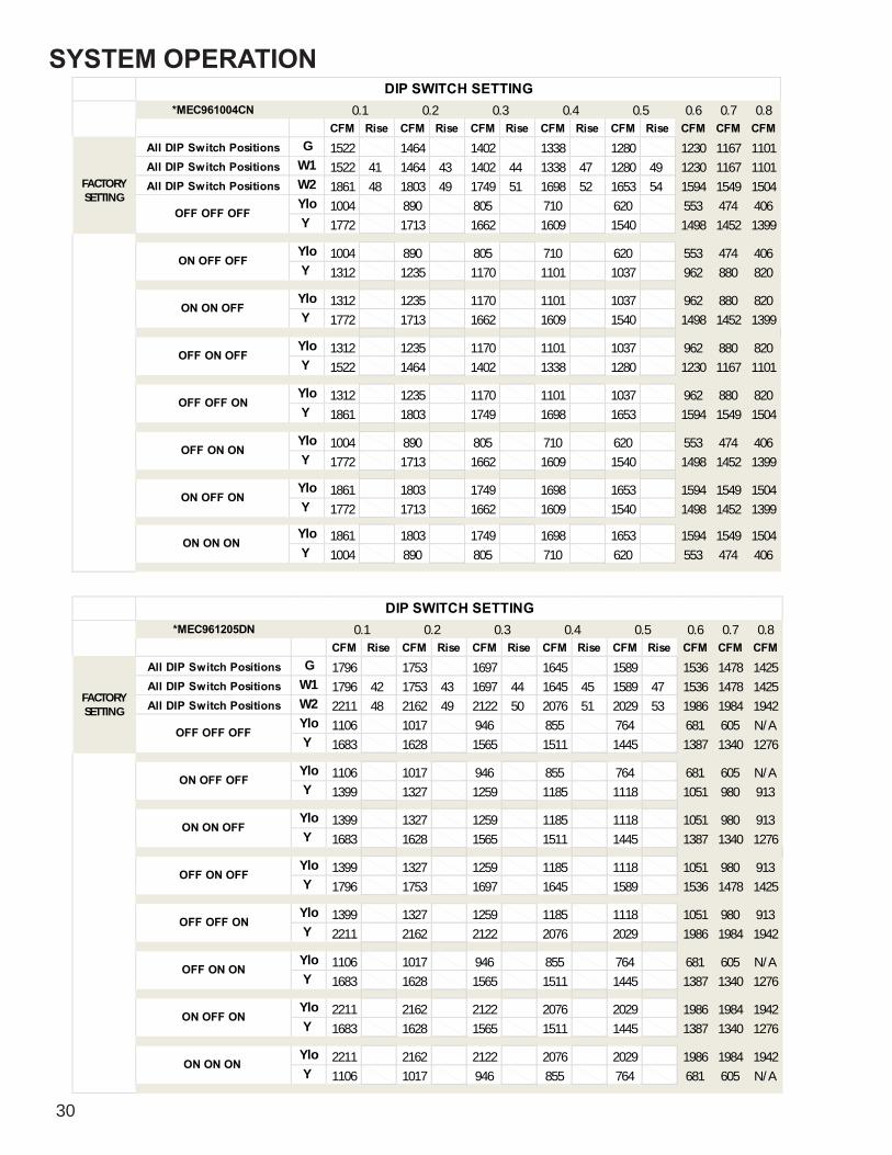
SYSTEM OPERATION
30
*MEC961004CN 0.6 0.7 0.8CFM Rise CFM Rise CFM Rise CFM Rise CFM Rise CFM CFM CFM
All DIP Switch Positions G 1522 1464 1402 1338 1280 1230 1167 1101All DIP Switch Positions W1 1522 41 1464 43 1402 44 1338 47 1280 49 1230 1167 1101All DIP Switch Positions W2 1861 48 1803 49 1749 51 1698 52 1653 54 1594 1549 1504
Ylo 1004 890 805 710 620 553 474 406Y 1772 1713 1662 1609 1540 1498 1452 1399
Ylo 1004 890 805 710 620 553 474 406Y 1312 1235 1170 1101 1037 962 880 820
Ylo 1312 1235 1170 1101 1037 962 880 820Y 1772 1713 1662 1609 1540 1498 1452 1399
Ylo 1312 1235 1170 1101 1037 962 880 820Y 1522 1464 1402 1338 1280 1230 1167 1101
Ylo 1312 1235 1170 1101 1037 962 880 820Y 1861 1803 1749 1698 1653 1594 1549 1504
Ylo 1004 890 805 710 620 553 474 406Y 1772 1713 1662 1609 1540 1498 1452 1399
Ylo 1861 1803 1749 1698 1653 1594 1549 1504Y 1772 1713 1662 1609 1540 1498 1452 1399
Ylo 1861 1803 1749 1698 1653 1594 1549 1504Y 1004 890 805 710 620 553 474 406
DIP SWITCH SETTING
OFF OFF ON
OFF ON ON
0.5
OFF OFF OFF
ON OFF OFF
ON ON OFF
OFF ON OFF
0.1 0.2 0.3
ON OFF ON
ON ON ON
0.4
FACTORYSETTING
*MEC961205DN 0.6 0.7 0.8CFM Rise CFM Rise CFM Rise CFM Rise CFM Rise CFM CFM CFM
All DIP Switch Positions G 1796 1753 1697 1645 1589 1536 1478 1425All DIP Switch Positions W1 1796 42 1753 43 1697 44 1645 45 1589 47 1536 1478 1425All DIP Switch Positions W2 2211 48 2162 49 2122 50 2076 51 2029 53 1986 1984 1942
Ylo 1106 1017 946 855 764 681 605 N/AY 1683 1628 1565 1511 1445 1387 1340 1276
Ylo 1106 1017 946 855 764 681 605 N/AY 1399 1327 1259 1185 1118 1051 980 913
Ylo 1399 1327 1259 1185 1118 1051 980 913Y 1683 1628 1565 1511 1445 1387 1340 1276
Ylo 1399 1327 1259 1185 1118 1051 980 913Y 1796 1753 1697 1645 1589 1536 1478 1425
Ylo 1399 1327 1259 1185 1118 1051 980 913Y 2211 2162 2122 2076 2029 1986 1984 1942
Ylo 1106 1017 946 855 764 681 605 N/AY 1683 1628 1565 1511 1445 1387 1340 1276
Ylo 2211 2162 2122 2076 2029 1986 1984 1942Y 1683 1628 1565 1511 1445 1387 1340 1276
Ylo 2211 2162 2122 2076 2029 1986 1984 1942Y 1106 1017 946 855 764 681 605 N/A
0.1 0.2
ON OFF ON
ON ON ON
0.3 0.4
DIP SWITCH SETTING
OFF ON ON
OFF OFF ON
0.5
OFF OFF OFF
ON OFF OFF
ON ON OFF
OFF ON OFF
FACTORYSETTING

SYSTEM OPERATION
31
UPRIGHT FILTER INSTALLATIONSDepending on the installation and/or customer preference,differing filter arrangements can be applied. Filters can beinstalled in the central return register and a side panel exter-nal filter rack kit (upflow filter kit # EFR02 As an alternative amedia air filter or electronic air cleaner can be used as therequested filter. Refer to the following minimum filter require-ment charts for determination of the minimum filter area toensure proper unit performance. The following figures showpossible filter locations.
Refer to Minimum Filter Area tables to determine filter arearequirement. NOTE: Filters can also be installed elsewherein the duct system such as a central return.
Horizontal InstallationsFilter(s) must be installed external to the furnace casing forhorizontal installations. For most installations it is prefer-able to use a central return with filters installed in the ductbehind the return air grill. In this way filter replacement isrelatively simple by merely removing the grille, rather thangoing into the attic or crawl space.
ADDITIONAL FILTERING ACCESSORIES
External Filter Rack Kit (EFR02)The external filter rack kit is intended to provide a locationexternal to the furnace casing, for installation of a perma-nent filter on upflow model furnaces. The rack is designed tomount over the indoor blower compartment area of eitherside panel, and provide filter retention as well as a locationfor attaching return air ductwork.
Electronic Air Cleaner (ASAS and GSAS) or Media AirCleaner (AMU and GMU)The electronic air cleaner and media air cleaner are multi-positional high efficiency air filtration devices that can beinstalled in any position, except with the access door facingdown. The best location for the air cleaner is in the return airduct next to the blower compartment. Before installing theair cleaner, consider the application. The electronic air cleanermust be readily accessible for periodic inspection and clean-ing of the pre-filters and electronic cells while the media aircleaner must be readily accessible for periodic inspectionand replacement of the Media Air Cleaner (AMU and GMU)filter cartridge (3 per carton) M0-1056, M1-1056, M2-1056,M8-1056, to maintain maximum efficiency and trouble-freeoperation. Carbon Filters 1156-3 and 1856-3 (set of 3) arealso available. See Product Catalog for exact filter for yourmodel. A full line of air filtration and indoor air quality prod-ucts are available and can be seen at www.goodmanmfg.com.
SEQUENCE OF OPERATION
POWER UP:· When power is supplied, the control will energize the
Red LED, microcomputer runs its self-check routine.
· The control will check the status of the gas valve cir-cuitry.
· Line polarity is checked.· The control then enters standby waiting for a call for
heat or cool.· The Furnace status LED will display a slow green
flash signaling standby mode
HEAT MODE: Call For 1st Stage Heat
· On a call for first stage heat, the thermostat contactsclose signaling the control module.
· The microcomputer runs its self-check routine.· The Amber LED will display a slow flash signaling
normal heat operation.· The control module checks the high limit (and/or aux-
iliary limit) switch(es) for normally closed contacts.· The control checks the low pressure switch for a
shorted condition.· The gas valve relay status is checked for proper op-
eration. Once the low pressure switch is detectedopen, the inducer blower is energized at high speedand the humidifier is enabled.
· The low pressure switch is checked for closure.· Once the low pressure switch is closed, the pre-purge
period begins. The inducer will be energized at highspeed for the pre-purge period.
· Following the completion of pre-purge, the inducerswitches to low speed and the igniter warm up periodbegins.
· After completion of the igniter warm up period:- Trial for ignition begins.- The first stage of the gas valve is energized.
· The igniter is de-energized when flame is sensed orat the conclusion of the ignition activation period (IAP),whichever comes first.
· When flame is sensed, the delay to heat on periodbegins timing.
· Retry counter is zeroed, if after 10 seconds the flameis sensed:- Control enters normal operating loop where all
inputs are continuously checked.· After the delay to heat on period, the circulator fan is
energized at the low heat speed.· The air cleaner will be energized with the circulator.· If the call for heat is lost while the control is in the trial
for ignition period without flame being detected, thecontrol will turn off the gas valve and igniter. The con-trol then enters the post-purge routine. The post-purgetime will be increased to 60 seconds. After complet-ing the post-purge, the control resumes normal op-eration.
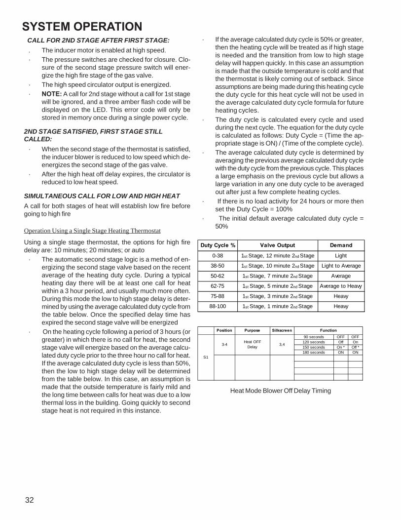
SYSTEM OPERATION
32
CALL FOR 2ND STAGE AFTER FIRST STAGE:. The inducer motor is enabled at high speed.· The pressure switches are checked for closure. Clo-
sure of the second stage pressure switch will ener-gize the high fire stage of the gas valve.
· The high speed circulator output is energized.· NOTE: A call for 2nd stage without a call for 1st stage
will be ignored, and a three amber flash code will bedisplayed on the LED. This error code will only bestored in memory once during a single power cycle.
2ND STAGE SATISFIED, FIRST STAGE STILLCALLED:
· When the second stage of the thermostat is satisfied,the inducer blower is reduced to low speed which de-energizes the second stage of the gas valve.
· After the high heat off delay expires, the circulator isreduced to low heat speed.
SIMULTANEOUS CALL FOR LOW AND HIGH HEATA call for both stages of heat will establish low fire beforegoing to high fire
Operation Using a Single Stage Heating Thermostat
Using a single stage thermostat, the options for high firedelay are: 10 minutes; 20 minutes; or auto
· The automatic second stage logic is a method of en-ergizing the second stage valve based on the recentaverage of the heating duty cycle. During a typicalheating day there will be at least one call for heatwithin a 3 hour period, and usually much more often.During this mode the low to high stage delay is deter-mined by using the average calculated duty cycle fromthe table below. Once the specified delay time hasexpired the second stage valve will be energized
· On the heating cycle following a period of 3 hours (orgreater) in which there is no call for heat, the secondstage valve will energize based on the average calcu-lated duty cycle prior to the three hour no call for heat.If the average calculated duty cycle is less than 50%,then the low to high stage delay will be determinedfrom the table below. In this case, an assumption ismade that the outside temperature is fairly mild andthe long time between calls for heat was due to a lowthermal loss in the building. Going quickly to secondstage heat is not required in this instance.
· If the average calculated duty cycle is 50% or greater,then the heating cycle will be treated as if high stageis needed and the transition from low to high stagedelay will happen quickly. In this case an assumptionis made that the outside temperature is cold and thatthe thermostat is likely coming out of setback. Sinceassumptions are being made during this heating cyclethe duty cycle for this heat cycle will not be used inthe average calculated duty cycle formula for futureheating cycles.
· The duty cycle is calculated every cycle and usedduring the next cycle. The equation for the duty cycleis calculated as follows: Duty Cycle = (Time the ap-propriate stage is ON) / (Time of the complete cycle).
· The average calculated duty cycle is determined byaveraging the previous average calculated duty cyclewith the duty cycle from the previous cycle. This placesa large emphasis on the previous cycle but allows alarge variation in any one duty cycle to be averagedout after just a few complete heating cycles.
· If there is no load activity for 24 hours or more thenset the Duty Cycle = 100%
· The initial default average calculated duty cycle =50%
Duty Cycle % Valve Output Demand
0-38 1st Stage, 12 minute 2nd Stage Light
38-50 1st Stage, 10 minute 2nd Stage Light to Average
50-62 1st Stage, 7 minute 2nd Stage Average
62-75 1st Stage, 5 minute 2nd Stage Average to Heavy
75-88 1st Stage, 3 minute 2nd Stage Heavy
88-100 1st Stage, 1 minute 2nd Stage Heavy
Position Purpose Silkscreen90 seconds OFF OFF
120 seconds Off On150 seconds On * Off *180 seconds ON ON
3,4
Function
S1
3-4Heat OFF
Delay
Heat Mode Blower Off Delay Timing
SYSTEM OPERATION
33
COOLING MODE:
LOW STAGE COOLING MODE SEQUENCE:· On a call for lo cool, the Ylo and G thermostat con-
tacts close signaling the control module.· The LED will display a “GREEN”1 flash· The compressor and condenser fan are energized. The
compressor is connected to the Ylo terminal of thecontrol module.
· The circulator fan is energized at lo cool speed after acool on delay. The electronic air cleaner will also beenergized.
· After the thermostat is satisfied, the compressor isde-energized
· Following the 60 second Cool Mode Fan Off Delayperiod, the cool circulator and air cleaner relay arede-energized.
· When the call for “Ylo”and “G”are presented simulta-neously, the control will honor the Cool On delay andkeep the circulator de-energized. After the Cool Ondelay, the circulator fan and air cleaner relays areenergized. The circulator fan is energized at the coolspeed. If a call for “G”is present prior to a call for “Ylo”,the circulator will remain at the FAN circulator speedduring the Cool On delay.
SINGLE COOLING STAGE THERMOSTAT OR 2NDSTAGE COOLING MODE SEQUENCE.
· On a call for cool, the Y and G thermostat contactsclose signaling the control module.
· The LED will display a “GREEN”2 flash· The compressor and condenser fan are energized. The
compressor is connected to the Y terminal of the con-trol module.
· The circulator fan is energized at cool speed after acool on delay. The electronic air cleaner will also beenergized.
· After the thermostat is satisfied, the compressor isde-energized and the Cool Mode FanOff Delay periodbegins.
· Following the 60 second Cool Mode Fan Off Delayperiod, the cool circulator and air cleaner relay arede-energized
MANUAL FAN ON:· On a call for Fan, the G thermostat contacts close
signaling the control module.· The LED will display a solid “GREEN”· When a call for G is received, the control will energize
the circulator in low heat speed after the fan on delaytime expires. The electronic air cleaner will also beenergized at this time.
· When the thermostat fan switch is moved to the ONposition, the circulator blower is energized at low heatspeed and the electronic air cleaner is also energized
· When the thermostat fan switch is moved back to theAUTO position, the circulator fan and air cleaner relayare de-energized and the control awaits a thermostatcall for heat or cool.
· Exception: During the Cool “On”delay, the control willnot respond to the fan input. If the fan was called priorto the call for cool, the circulator will remain ener-gized during the Cool “On”delay.
· If the fan is called prior to a call for heat, the circulatorwill remain energized during the entire call for heatsequence.

ACCESSORIES
34
GME95 & AMEH96 FURNACE ACCESSORIES
● Approved Accessory for this model
Not Approved for this model
(2) W/R & HW 2 stg valve(4) 7,000 - 11,000 ft altitude(5) 7,000 - 9,000 ft altitude(6) 9,001 - 11,000 ft altitude
MODELNUMBER
EFR02 AFE18 - 6 0A AMU / GMU AS AS /GSAS
0 17 0K0 0 00 0 S 0 17 0K0 0 00 1S
Desc riptionEFR
Exte rna l Filte r Ra ck
Dua l Fue l Kit
Me dia Air Cle ane rs
Elec tronicAir
Cle a ner
Conce ntric S ide Wa ll
Flush Mount V ent Kit (3 ")
Conc e ntric S ide Wa ll
Flush Mount V e nt Kit (2 ")
*MEC9 6 0 3 02 BNAA ● ● ● ● ● ●
*MEC9 6 0 4 02 BNAA ● ● ● ● ● ●
*MEC9 6 0 6 03 BNAA ● ● ● ● ● ●
*MEC9 6 0 8 03 BNAA ● ● ● ● ● ●
*MEC9 6 10 0 4 CNAA ● ● ● ● ● ●
*MEC9 6 12 0 5 DNAA ● ● ● ● ●
MODELNUMBER
DCVK- 2 (CV ENT- 2 )
DCV K- 3 0(CV ENT- 3 )
LPM08 LP LP 0 3 RF0 0 0 14 2 FTK04
Desc riptionConc e ntric
V e nt Kit(2 ")
Conc entric V e nt Kit
(3 ")
P ropa ne Ga s
Conve rsion Kit
LP Low PressureS hut Of
Kit
V e nt Dra in Coupling
TwinningKit
*MEC9 6 0 3 02 BNAA ● ● ● ● ● ●
*MEC9 6 0 4 02 BNAA ● ● ● ● ● ●
*MEC9 6 0 6 03 BNAA ● ● ● ● ● ●
*MEC9 6 0 8 03 BNAA ● ● ● ● ● ●
*MEC9 6 10 0 4 CNAA ● ● ● ● ● ●
*MEC9 6 12 0 5 DNAA ● ● ● ● ●
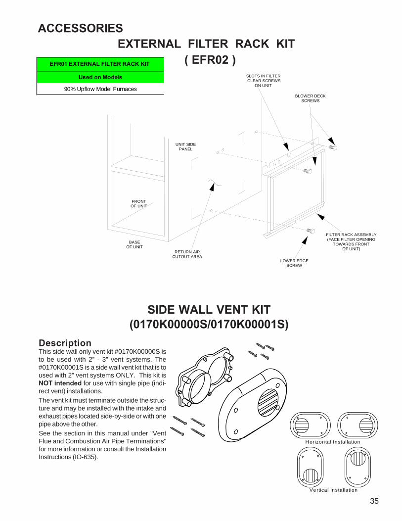
ACCESSORIES
35
EXTERNAL FILTER RACK KIT ( EFR02 )
BLOWER DECKSCREWS
SLOTS IN FILTER CLEAR SCREWS
ON UNIT
FRONT OF UNIT
RETURN AIRCUTOUT AREA
LOWER EDGESCREW
FILTER RACK ASSEMBLY(FACE FILTER OPENING
TOWARDS FRONTOF UNIT)
UNIT SIDE PANEL
BASEOF UNIT
90% Upflow Model Furnaces
EFR01 EXTERNAL FILTER RACK KIT
Used on Models
SIDE WALL VENT KIT(0170K00000S/0170K00001S)
Vertical Installa tion
H orizontal Installa tion
DescriptionThis side wall only vent kit #0170K00000S isto be used with 2” - 3” vent systems. The#0170K00001S is a side wall vent kit that is toused with 2" vent systems ONLY. This kit isNOT intended for use with single pipe (indi-rect vent) installations.The vent kit must terminate outside the struc-ture and may be installed with the intake andexhaust pipes located side-by-side or with onepipe above the other.See the section in this manual under "VentFlue and Combustion Air Pipe Terminations"for more information or consult the InstallationInstructions (IO-635).
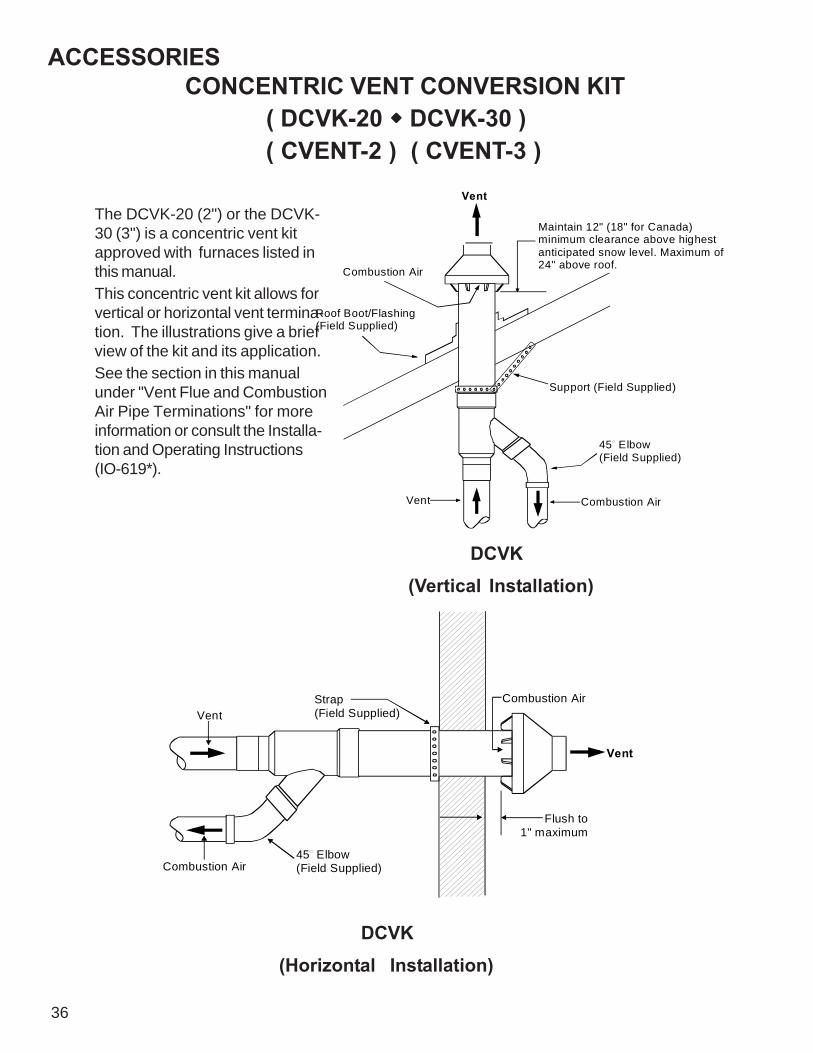
ACCESSORIES
36
Vent
Maintain 12" (18" for Canada) minimum clearance above highest anticipated snow level. Maximum of 24" above roof.Combustion Air
Roof Boot/Flashing(Field Supplied)
Support (Field Supplied)
45 Elbow(Field Supplied)
Combustion AirVent
CONCENTRIC VENT CONVERSION KIT( DCVK-20 DCVK-30 )( CVENT-2 ) ( CVENT-3 )
DCVK(Vertical Installation)
DCVK(Horizontal Installation)
The DCVK-20 (2") or the DCVK-30 (3") is a concentric vent kitapproved with furnaces listed inthis manual.This concentric vent kit allows forvertical or horizontal vent termina-tion. The illustrations give a briefview of the kit and its application.See the section in this manualunder "Vent Flue and CombustionAir Pipe Terminations" for moreinformation or consult the Installa-tion and Operating Instructions(IO-619*).
Vent
Combustion Air
Flush to 1" maximum
45 Elbow(Field Supplied)Combustion Air
VentStrap(Field Supplied)

ACCESSORY WIRING DIAGRAMS
37
HIGH VOLTAGE!DISCONNECT ALL POWER BEFORE SERVICING OR INSTALLING THISUNIT. MULTIPLE POWER SOURCES MAY BE PRESENT. FAILURE TODO SO MAY CAUSE PROPERTY DAMAGE, PERSONAL INJURY OR DEATH.
+5VDC
24VAC
G
POWER SUPPLYINPUT
POWER SUPPLY COMMONOUT TO HP CONTROL
P3-1
6.8K
P3-7
Y-HP
P1-6
P1-4
COMPRESSOR OUTPUT
P1-7
O
POWER SUPPLY OUTTO THERMOSTAT
24VAC
Q2
K3
W1
POWER SUPPLY INPUT(COMMON)
+VDC
E/W1
Y
P2-8
CALL FORREVERSING VALVE
P3-5
C
C
BLOWER FAN DEMANDOUTPUT
P3-3
P1-8
Y-STATY-FURN
C
P3-2
P1-1
P3-8
REVERSING VALVEOUTPUT
BREAK FOR ODT
FURNACE DEMANDOUTPUT
P1-3
R
24VAC
K4
HP CALL FOR FURNACE(DURING DEFROST)
W2
Y2-STATY2-FURN
CALL FORCOMPRESSOR
P2-7
P3-6
+VDC
Y2
O
REVERSINGVALVE OUTPUT
Q1
Y
P2-4
K1
OT-NO
Y
P2-9
CALL FOR 2ND STAGECOMPRESSOR
Y2
1.0K
G-FURN
P2-1
C
OT-C
C
SECOND STAGECOMPRESSOR OUTPUT
G
CALL FOREMERGENCY HEAT
W1-FURNW2-HP
F1 3A
OT-NC
24VAC
2ND STAGE COMPRESSORDEMAND OUTPUT
W1
CALL FORFURNACE HEAT
6.8K
G-STAT
+VDC
P3-4
FURNACE
P2-6
K2
ODT (OUTDOORTHERMOSTAT)
Y
R
SECOND STAGE FURNACEDEMAND OUTPUT
MICROPROCESSOR
Y2-HP
P1-5
CALL FOR 2ND STAGEFURNACE HEAT
O
W2
CALL FORBLOWER FAN
THERMOSTAT
P2-5
12
R
Y2
POWERSUPPLY
COMPRESSORCONTACTOR OUTPUT
O
HEAT
PUMP
P2-3
+5VDC
W2
P3-9
P2-2
E
POWER SUPPLY COMMONOUT TO THERMOSTAT
POWER SUPPLY OUTTO HP CONTROL
C
P1-2
ALL FUEL SYSTEM CONTROL BOARD - AFE18-60AThis wiring diagram is for reference only. Not all wiring is as shown above.
Refer to the appropriate wiring diagram for the unit being serviced.(For use with Heat Pumps in conjunction with 80% or 90% Single-Stage or Two-Stage Furnaces)
ALL FUEL SYSTEM CONTROL BOARD - AFE1860A

38
SERVICINGSERVICE NUMBERS
S-1 CHECKING VOLTAGE................................................................................................................................. 45S-2 CHECKING WIRING .................................................................................................................................... 45S-3A THERMOSTAT AND WIRING ....................................................................................................................... 45S-3B HEATING ANTICIPATOR .............................................................................................................................. 45S-4 CHECKING TRANSFORMER AND CONTROL CIRCUIT .............................................................................. 46S-16A CHECKING AIR CIRCULATOR BLOWER MOTOR (EEM) ........................................................................... 46S-200 CHECKING DUCT STATIC ........................................................................................................................... 46S-201 CHECKING TEMPERATURE RISE ............................................................................................................. 45S-300 CHECKING PRIMARY LIMIT CONTROL...................................................................................................... 45S-301 CHECKING AUXILIARY LIMIT CONTROL .................................................................................................... 48S-302 CHECKING FLAME ROLLOUT CONTROL .................................................................................................. 50S-303 INDUCED DRAFT BLOWER MOTOR.......................................................................................................... 50S-304 CHECKING GAS VALVE (REDUNDANT) .................................................................................................... 50S-305 CHECKING MAIN BURNERS ...................................................................................................................... 51S-306 CHECKING ORIFICES ................................................................................................................................ 51S-307 CHECKING GAS PRESSURE..................................................................................................................... 51S-308 CHECKING HOT SURFACE IGNITOR ......................................................................................................... 54S-309 CHECKING FOR FLASHBACK ................................................................................................................... 54S-310 CHECKING PRESSURE CONTROL ........................................................................................................... 54S-311 HIGH ALTITUDE APPLICATION (USA) ......................................................................................................... 55S-312 CHECKING FOR DELAYED IGNITION ........................................................................................................ 55S-313 CHECKING INTEGRATED IGNITION CONTROL BOARDS........................................................................ 55S-314 CHECKING FLAME SENSOR ................................................................................................................... 56

SERVICING
39
As more and more electronic's are introduced to the Heat-ing Trade, Polarization of incoming power and phasing ofprimary to secondary voltage on transformers becomesmore important.Polarization has been apparent in the Appliance industrysince the introduction of the three prong plug, however, theHeating Industry does not use a plug for incoming power,but is hard wired.Some of the electronic boards being used today, with flamerectification, will not function properly and/or at all withoutpolarization of incoming power. Some also require phasingbetween the primary and secondary sides of step-downtransformers.
THIS IS L1 OR THE HOT POWER LEG
INCOMING POWER
THIS IS THE COMMON OR NEUTRAL LEG
METER READS 120 VOLTS
METER READS 0 VOLTS
GN
D
GN
D
VOLT / OHM METER
VOLT / OHM METER
These then should be wired to the furnace accordingly.
CHECKING FOR PHASING - PRIMARY TO SECONDARY OF UNMARKED TRANSFORMERS*
If meter reads approximately 96 volts - the primary to secondary are in phase - if reads approximately 144 volts out ofphase - reverse low voltage wires.*NOTE: For flame rectification the common side of the secondary voltage (24 V) is cabinet grounded. If you were to benchtest a transformer the primary neutral and secondary common must be connected together for testing purposes.
Some transformers will display phasing symbols as shownin the illustration to the left to assist in determining propertransformer phasing.Checking for polarization and phasing should become ahabit in servicing. Let's start now.NOTE: Newer integrated ignition controls have a diagnos-tic flash code for reversed polarity (Refer to Troubleshoot-ing-Diagnostic Chart for LED Codes).
.. .
.. .
VOLT / OHM METER
GND
PRIM
ARY
SEC
OND
ARY
TRANSFORMER
R
C
METER READS 24 VOLTS
LINE VOLTAGE (NEUTRAL)
LINE VOLTAGE L1 (HOT)
VOLT / OHM METER
METER READS 120 VOLTS
VOLT / OHM METER
C
R
GNDN
L1
VOLT / OHM METER
READS 96 VOLTS - IN PHASE
C
R
GNDN
L1
VOLT / OHM METER
READS 144 VOLTS - OUT OF PHASE
C
R
GNDNEUTRAL
L1
PHASING SYMBOL
24 V 120 V

40
SERVICING
CUBIC FEET
1 1
One
1/4cu/ft
1/2cu/ft
1cu/ft
2cu/ft
5cu/ft
1/4cu/ft
1/2cu/ft
1cu/ft
2cu/ft
5cu/ft
10 90 180 360 720 1800 36 25 50 100 200 50011 82 164 327 655 1636 37 -- -- 97 195 48612 75 150 300 600 1500 38 23 47 95 189 47413 69 138 277 555 1385 39 -- -- 92 185 46214 64 129 257 514 1286 40 22 45 90 180 45015 60 120 240 480 1200 41 -- -- -- 176 43916 56 113 225 450 1125 42 21 43 86 172 42917 53 106 212 424 1059 43 -- -- -- 167 41918 50 100 200 400 1000 44 -- 41 82 164 40919 47 95 189 379 947 45 20 40 80 160 40020 45 90 180 360 900 46 -- -- 78 157 39121 43 86 171 343 857 47 19 38 76 153 38322 41 82 164 327 818 48 -- -- 75 150 37523 39 78 157 313 783 49 -- -- -- 147 36724 37 75 150 300 750 50 18 36 72 144 36025 36 72 144 288 720 51 -- -- -- 141 35526 34 69 138 277 692 52 -- -- 69 138 34627 33 67 133 265 667 53 17 34 -- 136 34028 32 64 129 257 643 54 -- -- 67 133 33329 31 62 124 248 621 55 -- -- -- 131 32730 30 60 120 240 600 56 16 32 64 129 32131 -- -- 116 232 581 57 -- -- -- 126 31632 28 56 113 225 563 58 -- 31 62 124 31033 -- -- 109 218 545 59 -- -- -- 122 30534 26 53 106 212 529 60 15 30 60 120 30035 -- -- 103 206 514
GAS RATE -- CUBIC FEET PER HOUR
Seconds for One
Revolution
Size of Test Dial Seconds for One
Revolution
Size of Test Dial

SERVICING
41
Service Problem No Heat Unsatisfactory Heat
POSSIBLE CAUSE
DOTS IN ANALYSISGUIDE INDICATE
"POSSIBLE CAUSE"SY
MPT
OM
Syst
em W
ill N
ot S
tart
Bur
ner
Won
't Ig
nite
Bur
ner I
gnite
s-Lo
cks
Out
Bur
ner S
huts
Off
prio
r to
T'S
tat b
eing
Sat
isfie
d
Sho
rt C
ycle
s
Long
Cyc
les
Soot
and
/or
Fum
es
Too
Muc
h H
eat
Not E
noug
h H
eat
Test MethodRemedy
See
Serv
ice
Proc
edur
e R
efer
ence
Power Failure • Test Voltage S-1Blown Fuse • Test Voltage S-4Loose Connection • Check Wiring S-2Shorted or Broken Wires • Check Wiring S-3ANo Low Voltage • Check Transformer S-4Faulty Thermostat • • • • • Check Thermostat S-3AFaulty Transformer • Check Transformer S-4Poor or High Resistance Ground • Measure Ground Resistance S-17BImproper Heat Anticipator Setting • • • • Adjust Heat Anticipator Setting S-3BImproper Thermostat Location • • • • Relocate Thermostat S-316Faulty Limit or Roll Out Switch • • Test Control S-300 / S-302Faulty Flame Sensor • Test Flame Sensor S-314Faulty Ignition Control • • • Test Control S-313Gas Valve or Gas Supply Shut Off • Turn Valves to On Position S-317Faulty Induced Draft Blower • • Test Induced Draft Motor S-303Faulty Blower Motor (PSC) • • Test Blower Motor (PSC) S-16A,B,CBroken or Shorted Ignitor • Test Ignitor S-308Dirty Flame Sensor, Low UA • Clean Flame Sensor S-314Stuck Gas Valve • • • Replace Gas Valve S-304Faulty Gas Valve • • • Replace Gas Valve S-304Open Auxil iary Limit • • Reset Control S-301Improper Air Flow or Distribution • • Check Duct Static S-200Cycling on Limit • • • Check Controls & Temperature Rise S-201 / S-300Delayed Ignition • Test for Delayed Ignition S-312Flashback • Test for Flashback S-309 / S-311Orifice Size • • • Check Orifices S-306 / S-311Gas Pressure • • • • Check Gas Pressure S-307Cracked Heat Exchanger • Check Burner Flames S-305Furnace Undersized • • Replace with Proper Size Furnace S-318Furnace Oversized • Replace with Proper Size Furnace S-318Faulty Pressure Switch • • • Test Pressure Switch S-310Blocked or Restricted Flue • Check Flue/Drawdown Pressure S-310Open Roll Out Switch • • Test Flame Roll Out Control S-302Bouncing On Pressure Switch • Test Negative Pressure S-310

TROUBLESHOOTING
42
SymptomsGreen
LED CodeAmber
LED CodeRed
LED CodeFault Description Check Cautions
•Furnace fails to operate •Control board LED is off
•None •None •None
•Defective disconnect switch •defective door switch • No 115 volt power •No 24 volt power
•Determine cause and restore proper high and low volt power supply
•Confirm electrically safe condition before proceeding with repairs
•Furnace is waiting for a call
•Solid ON •None •None•Furnace is not receiving a call
•None Required•Confirm electrically safe condition before proceeding with work
•Furnace fan only is running
•Rapid Flash •None •None•Furnace is receiving a call for fan (24 volts on G terminal
•None Required•Confirm electrically safe condition before proceeding with work
•Normal operation with low stage call for cooling (Ylo & G)
•One repeating flash
•None •None•Normal operation with low stage call for cooling (Ylo & G)
•None Required•Confirm electrically safe condition before proceeding with work
•Normal operation with high or single stage call for cooling (Y & G)
•Two repeating flashes
•None •None•Normal operation with high or single stage call for cooling (Y & G)
•None Required•Confirm electrically safe condition before proceeding with work
•Normal operation with low stage call for heat (W1)
•None•One repeating flash
•None•Normal operation with low stage call for heat (W1)
•None Required•Confirm electrically safe condition before proceeding with work
•Normal operation with high or single stage call for heat
•None•Two repeating flashes
•None•Normal operation with high or single stage call for heat
•None Required•Confirm electrically safe condition before proceeding with work
•Furnace does not operate, three Amber flashes on control board
•None•Three repeating flashes
•None •W2 call present without W1
•Faulty thermostat or thermostat wiring or improperly connected thermostat wires
•Confirm electrically safe condition before proceeding with repairs
•Furnace does not operate, four Amber flashes on control board
•None•Four repeating flashes
•None•Ylo or Y call present without G
•Faulty thermostat or thermostat wiring or improperly connected thermostat wires
•Confirm electrically safe condition before proceeding with repairs
•Furnace does not operate, rapid Amber flashes on control board
•None •Rapid •None •Low flame sense current
•Dirty / coated flame rod, poor flame, improper gas pressure, poor flame sense wire or connections
•Clean flame rod with steel wool. Confirm electrically safe condition before proceeding with repairs
•Furnace does not operate, one Red flash on control board
•None •None•One repeating flash
•Flame sensed when no flame should be present
•Gas valve stuck open, improper wiring to gas valve, shorted flame rod or wire
•Confirm electrical and gas safe conditions before proceeding with repairs
•Furnace does not operate, two Red flashes on control board, possible inducer operation
•None •None•Two repeating flashes
•Pressure switch stuck closed
•Faulty pressure switch, pressure switch wires shorted, control board inducer relay stuck closed
•Confirm electrically safe condition before proceeding with repairs
•Furnace does not operate, three Red flashes on control board
•None •None•Three repeating flashes
•Low fire pressure switch stuck open
•Faulty pressure switch, pressure switch or tubing or wiring / connection, control board inducer relay failed, vent pipe restriction / excessive elbows or length
•Confirm electrically safe condition before proceeding with repairs

TROUBLESHOOTING
43
SymptomsGreen
LED CodeAmber
LED CodeRed
LED CodeFault Description Check Cautions
•Furnace does not operate, four Red flashes on control board
•None •None•Four repeating flashes
•Open limit circuit, main limit, aux limit, or roll out switch
•Temperature rise, duct static, gas pressure, burner alignment, orifice plate position, wiring to all limits
•Confirm electrically safe condition before proceeding with repairs
•Furnace does not operate, five Red flashes on control board
•None •None•Five repeating flashes
•Limit & rollout circuit open for 15 minutes. Open control board fuse or rollout switch
•Control board fuse, Temperature rise, duct static, gas pressure, burner alignment, orifice plate position, wiring to all limits
•Confirm electrically safe condition before proceeding with repairs
•Furnace does not operate, six Red flashes on control board
•None •None•Six repeating flashes
•Pressure switch cycling lockout, pressure switch has opened 5 times in the same heating cycle
•Excessive venting restriction, leaking pressure switch tubing
•Confirm electrically safe condition before proceeding with repairs
•Furnace does not operate, seven Red flashes on control board
•None •None•Seven repeating flashes
•Lockout - excessive retries from flame not being proven during trial for ignition
•Gas pressure, gas valve, front cover pressure switch, flame rod
•Confirm electrical and gas safe conditions before proceeding with repairs
•Furnace does not operate, eight Red flashes on control board
•None •None•Eight repeating flashes
• Lockout - excessive recycles from flame proving being lost after being proven
•Gas pressure, gas valve, front cover pressure switch, flame rod
•Confirm electrical and gas safe conditions before proceeding with repairs
•Furnace does not operate, nine Red flashes on control board
•None •None•Nine repeating flashes
•Improper grounding or reverse polarity
•115 volt hot & neutral supply to furnace reversed, hot wire (door switch & L1 on control board) must read 115 volts to ground & neutral. Neutral wire should measure 0 volts to ground
•Confirm electrically safe condition before proceeding with repairs
•Furnace does not operate, ten Red flashes on control board
•None •None•Ten repeating flashes
•Gas valve current detected with no call for heat
•Verify gas valve is not receiving voltage from an electrical short. If valve wiring is correct replace control board
•Confirm electrical and gas safe conditions before proceeding with repairs
•Furnace does not operate, eleven Red flashes on control board, inducer running
•None •None•Eleven repeating flashes
•Open limit switch circuit for more than 5 minutes
•Re-set main power and check indoor blower operation
•Confirm electrically safe condition before proceeding with repairs
•Furnace does not operate, twelve Red flashes on control board
•None •None•Twelve repeating flashes
•Control board igniter relay not energizing igniter
•Replace control board•Confirm electrically safe condition before proceeding with repairs
•Furnace does not operate, control board Red LED on solid
•None •None •Solid ON •Control board internal fault •Replace control board•Confirm electrically safe condition before proceeding with repairs
•Furnace does not operate, control board Red LED rapid flash
•None •None •Rapid Flash •Twinning error •Correct twinning wiring•Confirm electrically safe condition before proceeding with repairs
•Furnace does not operate, control board Red LED with three double flashes
•None •None•Three double flashes
•Second stage pressure switch stuck open
•Verify pressure switch function & tubing, verify inducer operating and pulling enough vacuum to engage switch
•Confirm electrically safe condition before proceeding with repairs

DIAGNOSTIC CHARTRefer to the Troubleshooting Chart in the back of this manualfor assistance in determining the source of unit operational prob-lems.External Lockout
- A control lockout resulting from an external faultsensed by the control, such as an unsuccessful re-cycle or retry period, or a limit trip. Once in ExternalLockout, the control will shut down for a period of onehour before attempting another trial for ignition.
Internal Lockout- A failure internal to the control board.
FAULT RECALLRetrieving Fault CodesTo retrieve fault codes, push and release the “LAST ER-ROR” button for more than 1/5 second and less than 5 sec-onds (the LED will indicate this period by solid GREEN for1/5 second to 5 seconds). The LED will flash up to five storedfault codes, beginning with the most recent. If there are nofault codes in memory, the LED will flash two green flashes.The control will flash the most recent error first and the old-est error last. If multiple faults exist there will be 2 secondsbetween codes. Solid LED error codes will not be displayed.Fault Code ResetTo clear the fault code memory, push and hold the “LASTERROR” button for more than 5 seconds and less than 10seconds (the LED will indicate this period by RAPID GREENFLASH for 5 seconds to 10 seconds). The LED will flashthree green flashes when the memory has been cleared.
The ignition control is equipped with a momentary push but-ton switch that can be used to display on the diagnosticLED the last five faults detected by the control. The controlmust be in Standby Mode (no thermostat inputs) to use thefeature.Depress the push button switch for approximately 2 sec-onds. Release the switch when the LED is turned off. Thediagnostic LED will then display the flash codes associatedwith the last five detected faults. The order of display is themost recent fault to the least recent fault.
RESETTING FROM LOCKOUTFurnace lockout results when a furnace is unable to achieveignition after three attempts during a single call for heat. Itis characterized by a non-functioning furnace and a one flashdiagnostic LED code. If the furnace is in “lockout”, it can bereset in any of the following ways.
1. Automatic reset. The integrated control module willautomatically reset itself and attempt to resume normaloperations following a one hour lockout period.
2. Manual power interruption. Interrupt 115 volt power tothe furnace for 1 - 20 seconds.
3. Manual thermostat cycle. Lower the thermostat sothat there is no longer a call for heat then reset to previ-ous setting. Interrupt thermostat signal to the furnacefor 1 - 20 seconds.
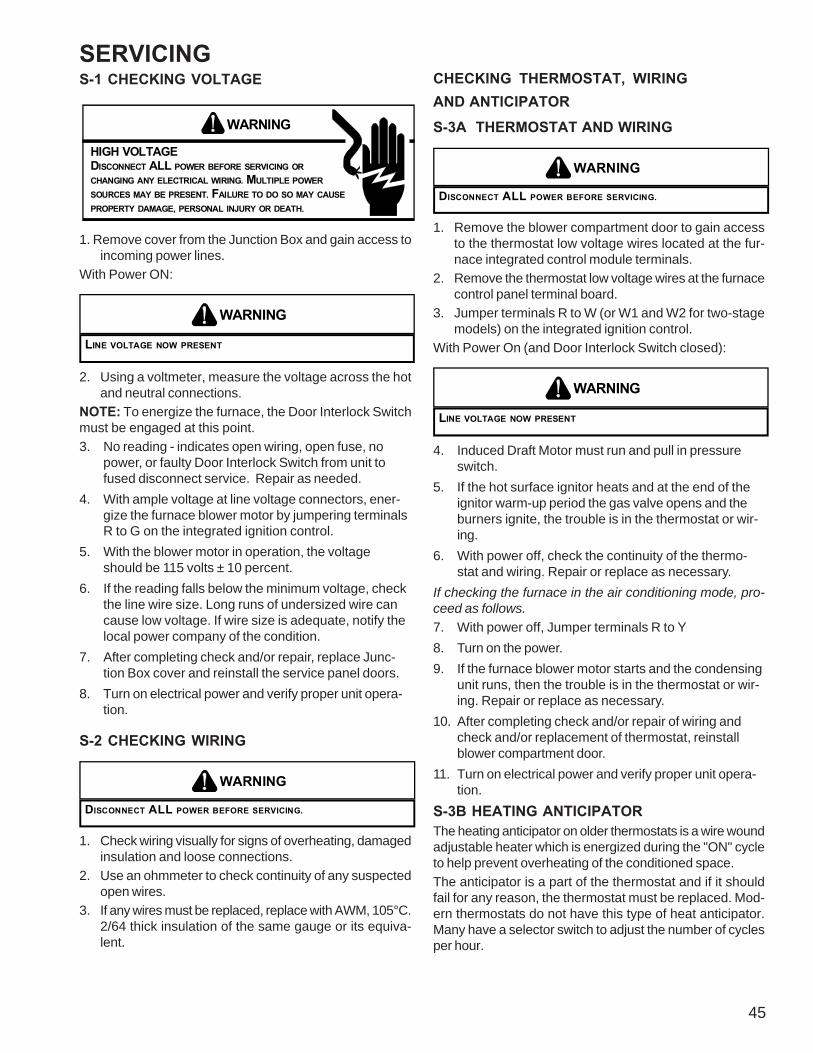
SERVICING
45
S-1 CHECKING VOLTAGE
WARNING
HIGH VOLTAGEDISCONNECT ALL POWER BEFORE SERVICING ORCHANGING ANY ELECTRICAL WIRING. MULTIPLE POWERSOURCES MAY BE PRESENT. FAILURE TO DO SO MAY CAUSEPROPERTY DAMAGE, PERSONAL INJURY OR DEATH.
1. Remove cover from the Junction Box and gain access toincoming power lines.
With Power ON:
LINE VOLTAGE NOW PRESENT
WARNING
2. Using a voltmeter, measure the voltage across the hotand neutral connections.
NOTE: To energize the furnace, the Door Interlock Switchmust be engaged at this point.3. No reading - indicates open wiring, open fuse, no
power, or faulty Door Interlock Switch from unit tofused disconnect service. Repair as needed.
4. With ample voltage at line voltage connectors, ener-gize the furnace blower motor by jumpering terminalsR to G on the integrated ignition control.
5. With the blower motor in operation, the voltageshould be 115 volts ± 10 percent.
6. If the reading falls below the minimum voltage, checkthe line wire size. Long runs of undersized wire cancause low voltage. If wire size is adequate, notify thelocal power company of the condition.
7. After completing check and/or repair, replace Junc-tion Box cover and reinstall the service panel doors.
8. Turn on electrical power and verify proper unit opera-tion.
S-2 CHECKING WIRING
DISCONNECT ALL POWER BEFORE SERVICING.
WARNING
1. Check wiring visually for signs of overheating, damagedinsulation and loose connections.
2. Use an ohmmeter to check continuity of any suspectedopen wires.
3. If any wires must be replaced, replace with AWM, 105°C.2/64 thick insulation of the same gauge or its equiva-lent.
CHECKING THERMOSTAT, WIRINGAND ANTICIPATOR
S-3A THERMOSTAT AND WIRING
DISCONNECT ALL POWER BEFORE SERVICING.
WARNING
1. Remove the blower compartment door to gain accessto the thermostat low voltage wires located at the fur-nace integrated control module terminals.
2. Remove the thermostat low voltage wires at the furnacecontrol panel terminal board.
3. Jumper terminals R to W (or W1 and W2 for two-stagemodels) on the integrated ignition control.
With Power On (and Door Interlock Switch closed):
LINE VOLTAGE NOW PRESENT
WARNING
4. Induced Draft Motor must run and pull in pressureswitch.
5. If the hot surface ignitor heats and at the end of theignitor warm-up period the gas valve opens and theburners ignite, the trouble is in the thermostat or wir-ing.
6. With power off, check the continuity of the thermo-stat and wiring. Repair or replace as necessary.
If checking the furnace in the air conditioning mode, pro-ceed as follows.
7. With power off, Jumper terminals R to Y8. Turn on the power.9. If the furnace blower motor starts and the condensing
unit runs, then the trouble is in the thermostat or wir-ing. Repair or replace as necessary.
10. After completing check and/or repair of wiring andcheck and/or replacement of thermostat, reinstallblower compartment door.
11. Turn on electrical power and verify proper unit opera-tion.
S-3B HEATING ANTICIPATORThe heating anticipator on older thermostats is a wire woundadjustable heater which is energized during the "ON" cycleto help prevent overheating of the conditioned space.The anticipator is a part of the thermostat and if it shouldfail for any reason, the thermostat must be replaced. Mod-ern thermostats do not have this type of heat anticipator.Many have a selector switch to adjust the number of cyclesper hour.

46
SERVICINGS-4 CHECKING TRANSFORMER AND Control CIR-
CUITA step-down transformer 120 volt primary to 24 volt second-ary, 40 VA (Heating and Cooling Models) supplies amplecapacity of power for either operation.
WARNING
HIGH VOLTAGEDISCONNECT ALL POWER BEFORE SERVICING ORCHANGING ANY ELECTRICAL WIRING. MULTIPLE POWERSOURCES MAY BE PRESENT. FAILURE TO DO SO MAY CAUSEPROPERTY DAMAGE, PERSONAL INJURY OR DEATH.
1. Remove blower compartment door to gain access to thethermostat low voltage wires located at the furnace inte-grated control module.
2. Remove the thermostat low voltage wires at the furnaceintegrated control module terminals.
With Power On (and Door Interlock Switch closed):
LINE VOLTAGE NOW PRESENT
WARNING
3. Use a voltmeter, check voltage across terminals Rand C. Must read 24 VAC.
4. No voltage indicates faulty transformer, open fuse, badwiring, bad splice, or open door interlock switch.
5. Check transformer primary voltage at incoming linevoltage connections, fuse, splices, and blower door in-terlock switch.
6. If line voltage is available to the primary side of trans-former and not at secondary side, the transformer isinoperative. Replace.
7. After completing check and/or replacement of trans-former and check and/or repair of control circuit, rein-stall blower compartment door.
8. Turn on electrical power and verify proper unit opera-tion.
LINE VOLTAGE NOW PRESENT
WARNING
WARNING
HIGH VOLTAGEDISCONNECT ALL POWER BEFORE SERVICING ORINSTALLING THIS UNIT. MULTIPLE POWER SOURCES MAYBE PRESENT. FAILURE TO DO SO MAY CAUSE PROPERTYDAMAGE, PERSONAL INJURY OR DEATH.
S-16A CHECKING AIR CIRCULATOR BLOWERMOTOR (MULTI-SPEED ECM MOTOR)
DISCONNECT ALL POWER BEFORE SERVICING.
WARNING
1. Remove blower compartment door to gain access to thecirculator blower motor and integrated ignition control.
2. Check for any obstruction that would keep the fan wheel/ fan motor from turning.
3. Check wiring, the motor has two wiring harnesses, amain harness and a control harness. The main pin har-ness has:White neutral wire connected to the Neutral terminal onthe control board.Black wire connected to the CIRC H terminal on the con-trol board.Red wire connected to the COM terminal, which is afemale spade connection next to the T1 – T4 wires onthe control board.Green ground wire connected to cabinet groundThe control harness has:Blue wire connected to T1 on the control board.Red wire connected to T2 on the control board.Orange wire connected to T3 on the control board.Black wire connected to T4 on the control board.The multi-speed ECM motor requires a line voltage powersupply (black connected to CIRC H and white connectedto neutral on the control board) as well as a signal onone of the speed taps (T1-T4).The speed tap voltage is D.C. and can vary dependingon S2 DIP switch selection. The voltage reading fromany one of the speed taps is referenced between thefemale COM terminal next to the speed taps on the con-trol board. From COM to T1 or T2, 6-7 VDC when ener-gized. From COM to T3, 13-14 VDC when energized.From COM to T4, 6-7 or 13-14 VDC depending on S2settings.
S-200 CHECKING DUCT STATICThe maximum and minimum allowable external static pres-sures are found in the specification section. These tablesalso show the amount of air being delivered at a given staticby a given motor speed or pulley adjustment.The furnace motor cannot deliver proper air quantities (CFM)against statics other than those listed.Too great of an external static pressure will result in insuffi-cient air that can cause excessive temperature rise, result-ing in limit tripping, etc. Whereas not enough static mayresult in motor overloading.

SERVICING
47
To determine proper air movement, proceed as follows:1. With clean filters in the furnace, use a draft gauge (in-
clined manometer) to measure the static pressure ofthe return duct at the inlet of the furnace. (Negative Pres-sure)
2. Measure the static pressure of the supply duct. (Posi-tive Pressure)
3. Add the two (2) readings together for total external staticpressure.
NOTE: Both readings may be taken simultaneously andread directly on the manometer if so desired. If an air condi-tioner coil or Electronic Air Cleaner is used in conjunctionwith the furnace, the readings must also include theses com-ponents, as shown in the following drawing.4. Consult proper tables for the quantity of air.If the total external static pressure exceeds the minimum ormaximum allowable statics, check for closed dampers, reg-isters, undersized and/or oversized poorly laid out duct work.
Checking Static Pressure
S-201 CHECKING TEMPERATURE RISEThe more air (CFM) being delivered through a given furnace,the less the rise will be; so the less air (CFM) being deliv-ered, the greater the rise. The temperature rise should beadjusted in accordance to a given furnace specificationsand its external static pressure. An incorrect temperaturerise may result in condensing in or overheating of the heatexchanger. An airflow and temperature rise table is providedin the blower performance specification section. Determineand adjust temperature rise as follows:
1. Operate furnace with burners firing for approximately tenminutes. Check BTU input to furnace - do not exceedinput rating stamped on rating plate. Ensure all registersare open and all duct dampers are in their final (fully orpartially open) position.
2. Place thermometers in the return and supply ducts asclose to the furnace as possible. Thermometers mustnot be influenced by radiant heat by being able to “see”the heat exchanger.
SUPPLY AIR
RETURN AIR
Checking Temperature Rise
3. Subtract the return air temperature from the supply airtemperature to determine the air temperature rise. Allowadequate time for thermometer readings to stabilize.
4. Adjust temperature rise by adjusting the circulator blowerspeed. Increase blower speed to reduce temperature rise.Decrease blower speed to increase temperature rise.Refer to Circulator Blower Speed section in the ProductDesign section of this manual for speed changing de-tails. Temperature rise is related to the BTUH output ofthe furnace and the amount of air (CFM) circulated overthe heat exchanger. Measure motor current draw to de-termine that the motor is not overloaded during adjust-ments.
S-300 CHECKING PRIMARY LIMIT CONTROLAll primary limit controls are nonadjustable, automatic re-set, bi-metal type limit control. Refer to the following draw-ing for the location of the primary limit.

48
SERVICING
*
*
*
* *
*
*
2
PRIMARY LIMIT CONTROL
Primary Limit Control Location(90% Upflow Furnace Shown)
The following drawing illustrates the style of limit switchesused on the 90% furnaces.
ENCLOSED DISK
FRONT VIEW SIDE VIEW
Primary Limit Control Style(90% Furnaces)
WARNING
HIGH VOLTAGEDISCONNECT ALL POWER BEFORE SERVICING ORCHANGING ANY ELECTRICAL WIRING. MULTIPLE POWERSOURCES MAY BE PRESENT. FAILURE TO DO SO MAY CAUSEPROPERTY DAMAGE, PERSONAL INJURY OR DEATH.
1. Remove burner compartment door to gain access tothe primary limit.
2. Remove low voltage wires at limit control terminals.3. With an ohmmeter, test between these two terminals
as shown in the following drawing. The ohmmetershould read continuous unless heat exchanger tem-perature is above limit control setting. If not as above,replace the control.
LIMIT FAULT CODESIf the control detects the high limit circuit open, the REDLED will flash FOUR times and energize the inducer andindoor blower.
If the limit circuit opens five times within a single call forheat, the furnace will go into lockout for one hour. The REDLED will display a FOUR flash code during this time. Thecontrol board can be reset by cycling 115 volt power to thefurnace.If the limit circuit opens and does not close within five min-utes, the control assumes the blower has failed the REDLED will flash ELEVEN times.If the limit circuit opens and does not close within fifteenminutes, the control assumes the manual rollout or fusehas opened and the RED LED will flash FIVE times. Thecontrol will enter a one hour lockout and the inducer will runcontinuously.In an open limit condition the red LED will flash as describedabove but the error code will not be stored in memory untilthe limit resets or until 15 minutes has elapsed. So if thelimit resets in less than 5 minutes a four flash code will bestored. If the limit resets in more than 5 but less than 15minutes, an eleven flash code will be stored. If the limit isstill open after 15 minutes, a five flash code will be stored.
VOLT / OHM METER
COLORIDENTIFYING TAB
Testing Primary Limit Control
4. After completing check and/or replacement of primarylimit control, reinstall burner compartment door.
5. Turn on electrical power and verify proper unit opera-tion.
S-301 CHECKING AUXILIARY LIMIT CONTROLThe auxiliary limit control is designed to prevent furnaceoperation in case of main blower failure in horizontal instal-lations. It may also open if the power supply is interruptedwhile the furnace is firing.The auxiliary limit control is suitable for both horizontal rightand horizontal left installations. Regardless of airflow direc-tion, it does not need to be relocated. The (2) two auxiliarylimits are located on the blower housing (one on each side),as shown in the following illustration.

SERVICING
49
AUXILIARY LIMIT CONTROL
AUXILIARY LIMIT CONTROL
BLOWER HOUSING
Auxiliary Limit Control Location
WARNING
HIGH VOLTAGEDISCONNECT ALL POWER BEFORE SERVICING ORINSTALLING THIS UNIT. MULTIPLE POWER SOURCES MAYBE PRESENT. FAILURE TO DO SO MAY CAUSE PROPERTYDAMAGE, PERSONAL INJURY OR DEATH.
1. Remove blower compartment door to gain access tothe auxiliary.
2. Remove the wires from the auxiliary limit control ter-minals.
3. Using an ohmmeter, test for continuity across thetwo terminals.
VOLT / OHM METER
RED RESETBUTTON
COLORIDENTIFYING TAB
Testing Auxiliary Limit Control

50
SERVICING302 CHECKING FLAME ROLLOUT CONTROLA temperature activated manual reset control is mounted tothe manifold assembly as shown in the following illustration.
*
*
*
* *
*
*
2
FLAME ROLLOUTSWITCHES
Flame Rollout Switch Location(90% Upflow Furnace Shown)
The control is designed to open should a flame roll out oc-cur. An over firing condition or flame impingement on theheat shield may also cause the control to open. If the rolloutcontrol opens, the air circulation blower will run continuously.
LINE VOLTAGE NOW PRESENT
WARNING
1. Remove the burner compartment door to gain access tothe rollout switch(es) mounted to burner bracket.
2. Reset the manual roll out switch3. Remove wires from roll out switch4. Using an ohmmeter, check for continuity across the
switch.5. If the switch will not close after manually resetting, it
must be replaced.6. Measure the voltage between each side of the rollout
control and ground during the ignition attempt. If a rollout switch has tripped, it is important to find out why.Possible causes could be flame impingement, orifice plateout of position, burners with excessive cross-over slotdimension, over-firing, improper orifices, improper gaspressure, air leaking from around the heat exchangerinto the burner compartment, air leaking through the heatexchanger itself.
7. After check and/or replacement of rollout switch, rein-stall burner compartment door and verify proper unit op-eration.
S-303 INDUCED DRAFT BLOWER Motor
WARNING
HIGH VOLTAGEDISCONNECT ALL POWER BEFORE SERVICING ORINSTALLING THIS UNIT. MULTIPLE POWER SOURCES MAYBE PRESENT. FAILURE TO DO SO MAY CAUSE PROPERTYDAMAGE, PERSONAL INJURY OR DEATH.
1. Remove burner compartment door to gain access tothe induced draft blower motor.
2. Disconnect the motor wire leads from its connectionpoint at the induced draft motor.
3. Using a ohmmeter, test for continuity between eachof the motor leads.
4. Touch one probe of the ohmmeter to the motor frame(ground) and the other probe in turn to each lead.If the windings do not test continuous or a reading isobtained to ground, replace the motor.
5. If the windings have a continuity reading, reconnectwires. Turn power on to the furnace and turn the ther-mostat on in the heating mode. Check voltage for115V at the induced draft motor terminals during thetrial for ignition. If you have 115V and the motor doesnot run, replace the induced draft motor.
6. After completing check and/or replacement of in-duced draft motor, reinstall burner compartment door.
7. Turn on electrical power and verify proper unit opera-tion.
S-304 CHECKING GAS VALVE (Redundant)A combination redundant operator type gas valve which pro-vides all manual and automatic control functions requiredfor gas fired heating equipment is used.The valve provides control of main burner gas flow, pressureregulation, and 100 percent safety shut-off.

SERVICING
51
Two stage gas valves always require 24 volts between com-mon and low fire (main coil) to open. Also, the furnace frontcover pressure switch is wired in series with the low (main)solenoid of the gas valve. In the event of a non functioninggas valve, always check the front cover pressure switch.Also see section S-307 on Checking Gas Pressure andsection S-310 on Checking Pressure SwitchesS-305 CHECKING MAIN BURNERS
BURNERS
Burners have been redesigned for 34.5" chassis furnaces.Overall length and width dimensions remain the same as40" model burners. The burners used 34.5" models haveburner head insert with larger diameter center hole and alarger number of surrounding holes.The main burners are used to provide complete combustionof various fuels in a limited space, and transfer this heat ofthe burning process to the heat exchanger.Proper ignition, combustion, and extinction are primarilydue to burner design, orifice sizing, gas pressure, primaryand secondary air, vent and proper seating of burners.
34.5" Burner
WARNING
DISCONNECT ALL GAS AND ELECTRICAL POWER SUPPLY.
In checking main burners, look for signs of rust, oversizedand undersized carry over ports restricted with foreign ma-terial, etc, burner cross-over slots should not be altered insize.
S-306 CHECKING ORIFICES*MEC96 model furnaces have factory installed #45 naturalgas orifices (except *MEC96030 which has #50).The only time resizing is required is when a reduction infiring rate is required for an increase in altitude or a furnaceis being converted for use with LP gas.Orifices should be treated with care in order to prevent dam-age. They should be removed and installed with a box-endwrench in order to prevent distortion. In no instance shouldan orifice be peened over and redrilled. This will change theangle or deflection of the vacuum effect or entraining of pri-mary air, which will make it difficult to adjust the flame prop-erly. This same problem can occur if an orifice spud of adifferent length is substituted.
WARNING
DISCONNECT ALL GAS AND ELECTRICAL POWER SUPPLY.
1. Check orifice visually for distortion and/or burrs.2. Check orifice size with orifice sizing drills.
A
GASSTREAM B
The length of Dimension "A" determines the angle of GasStream "B".
DENT ORBURR
GASSTREAM B
A dent or burr will cause a severe deflection of the gas stream.
S-307 CHECKING GAS PRESSUREGas Supply Pressure Measurement
GAS PRESSURE TEST
The line pressure supplied to the gas valve must be within therange specified below. The supply pressure can be measuredat the gas valve inlet pressure tap or at a hose fitting installed inthe gas piping drip leg. The supply pressure must be measuredwith the burners operating. To measure the gas supply pres-sure, use the following procedure.
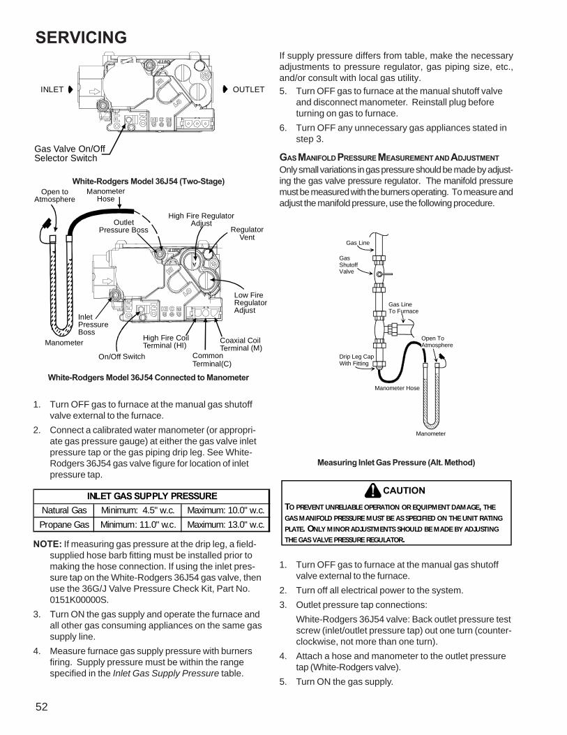
52
SERVICING
INLET OUTLET
Gas Valve On/OffSelector Switch
White-Rodgers Model 36J54 (Two-Stage)
InletPressureBoss
Low FireRegulatorAdjust
Manometer
ManometerHose
High Fire RegulatorAdjust
RegulatorVent
OutletPressure Boss
Open toAtmosphere
On/Off Switch
High Fire CoilTerminal (HI) Coaxial Coil
Terminal (M)CommonTerminal(C)
White-Rodgers Model 36J54 Connected to Manometer
1. Turn OFF gas to furnace at the manual gas shutoffvalve external to the furnace.
2. Connect a calibrated water manometer (or appropri-ate gas pressure gauge) at either the gas valve inletpressure tap or the gas piping drip leg. See White-Rodgers 36J54 gas valve figure for location of inletpressure tap.
Natural Gas Minimum: 4.5" w.c. Maximum: 10.0" w.c.Propane Gas Minimum: 11.0" w.c. Maximum: 13.0" w.c.
INLET GAS SUPPLY PRESSURE
NOTE: If measuring gas pressure at the drip leg, a field-supplied hose barb fitting must be installed prior tomaking the hose connection. If using the inlet pres-sure tap on the White-Rodgers 36J54 gas valve, thenuse the 36G/J Valve Pressure Check Kit, Part No.0151K00000S.
3. Turn ON the gas supply and operate the furnace andall other gas consuming appliances on the same gassupply line.
4. Measure furnace gas supply pressure with burnersfiring. Supply pressure must be within the rangespecified in the Inlet Gas Supply Pressure table.
If supply pressure differs from table, make the necessaryadjustments to pressure regulator, gas piping size, etc.,and/or consult with local gas utility.5. Turn OFF gas to furnace at the manual shutoff valve
and disconnect manometer. Reinstall plug beforeturning on gas to furnace.
6. Turn OFF any unnecessary gas appliances stated instep 3.
GAS MANIFOLD PRESSURE MEASUREMENT AND ADJUSTMENTOnly small variations in gas pressure should be made by adjust-ing the gas valve pressure regulator. The manifold pressuremust be measured with the burners operating. To measure andadjust the manifold pressure, use the following procedure.
Gas Line
GasShutoffValve
Gas Line To Furnace
Drip Leg Cap With Fitting
Manometer Hose
Manometer
Open ToAtmosphere
Measuring Inlet Gas Pressure (Alt. Method)
TO PREVENT UNRELIABLE OPERATION OR EQUIPMENT DAMAGE, THE GAS MANIFOLD PRESSURE MUST BE AS SPECIFIED ON THE UNIT RATING PLATE. ONLY MINOR ADJUSTMENTS SHOULD BE MADE BY ADJUSTING THE GAS VALVE PRESSURE REGULATOR.
CAUTION
1. Turn OFF gas to furnace at the manual gas shutoffvalve external to the furnace.
2. Turn off all electrical power to the system.3. Outlet pressure tap connections:
White-Rodgers 36J54 valve: Back outlet pressure testscrew (inlet/outlet pressure tap) out one turn (counter-clockwise, not more than one turn).
4. Attach a hose and manometer to the outlet pressuretap (White-Rodgers valve).
5. Turn ON the gas supply.
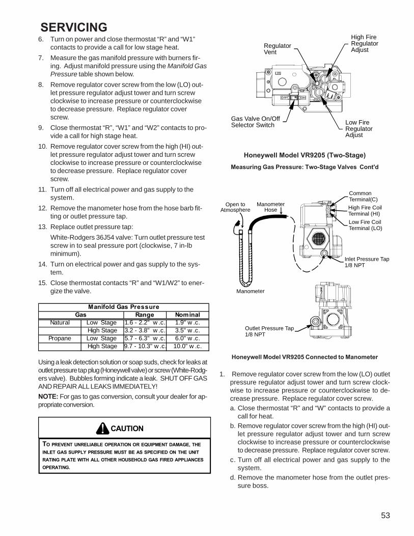
SERVICING
53
6. Turn on power and close thermostat “R” and “W1”contacts to provide a call for low stage heat.
7. Measure the gas manifold pressure with burners fir-ing. Adjust manifold pressure using the Manifold GasPressure table shown below.
8. Remove regulator cover screw from the low (LO) out-let pressure regulator adjust tower and turn screwclockwise to increase pressure or counterclockwiseto decrease pressure. Replace regulator coverscrew.
9. Close thermostat “R”, “W1” and “W2” contacts to pro-vide a call for high stage heat.
10. Remove regulator cover screw from the high (HI) out-let pressure regulator adjust tower and turn screwclockwise to increase pressure or counterclockwiseto decrease pressure. Replace regulator coverscrew.
11. Turn off all electrical power and gas supply to thesystem.
12. Remove the manometer hose from the hose barb fit-ting or outlet pressure tap.
13. Replace outlet pressure tap:White-Rodgers 36J54 valve: Turn outlet pressure testscrew in to seal pressure port (clockwise, 7 in-lbminimum).
14. Turn on electrical power and gas supply to the sys-tem.
15. Close thermostat contacts “R” and “W1/W2” to ener-gize the valve.
Range NominalNatural Low Stage 1.6 - 2.2" w .c. 1.9" w .c.
High Stage 3.2 - 3.8" w .c. 3.5" w .c.Propane Low Stage 5.7 - 6.3" w .c. 6.0" w .c.
High Stage 9.7 - 10.3" w .c. 10.0" w .c.
Manifold Gas PressureGas
Using a leak detection solution or soap suds, check for leaks atoutlet pressure tap plug (Honeywell valve) or screw (White-Rodg-ers valve). Bubbles forming indicate a leak. SHUT OFF GASAND REPAIR ALL LEAKS IMMEDIATELY!NOTE: For gas to gas conversion, consult your dealer for ap-propriate conversion.
TO PREVENT UNRELIABLE OPERATION OR EQUIPMENT DAMAGE, THEINLET GAS SUPPLY PRESSURE MUST BE AS SPECIFIED ON THE UNITRATING PLATE WITH ALL OTHER HOUSEHOLD GAS FIRED APPLIANCESOPERATING.
CAUTION
Gas Valve On/OffSelector Switch
RegulatorVent
High FireRegulatorAdjust
Low FireRegulatorAdjust
Honeywell Model VR9205 (Two-Stage)Measuring Gas Pressure: Two-Stage Valves Cont'd
i
Manometer
ManometerHose
CommonTerminal(C)High Fire CoilTerminal (HI)Low Fire Coil Terminal (LO)
Inlet Pressure Tap1/8 NPT
Open toAtmosphere
Outlet Pressure Tap1/8 NPT
Honeywell Model VR9205 Connected to Manometer
1. Remove regulator cover screw from the low (LO) outletpressure regulator adjust tower and turn screw clock-wise to increase pressure or counterclockwise to de-crease pressure. Replace regulator cover screw.a. Close thermostat “R” and “W” contacts to provide a
call for heat.b. Remove regulator cover screw from the high (HI) out-
let pressure regulator adjust tower and turn screwclockwise to increase pressure or counterclockwiseto decrease pressure. Replace regulator cover screw.
c. Turn off all electrical power and gas supply to thesystem.
d. Remove the manometer hose from the outlet pres-sure boss.
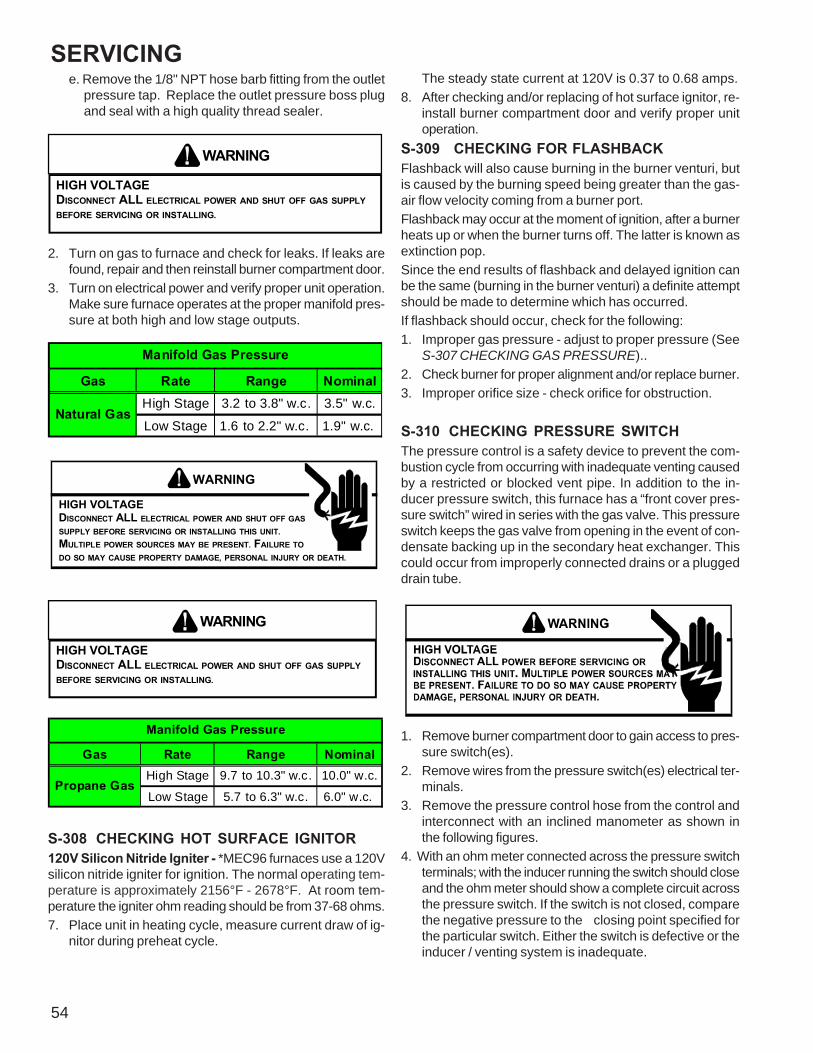
54
SERVICINGe. Remove the 1/8" NPT hose barb fitting from the outlet
pressure tap. Replace the outlet pressure boss plugand seal with a high quality thread sealer.
WARNING
HIGH VOLTAGEDISCONNECT ALL ELECTRICAL POWER AND SHUT OFF GAS SUPPLYBEFORE SERVICING OR INSTALLING.
2. Turn on gas to furnace and check for leaks. If leaks arefound, repair and then reinstall burner compartment door.
3. Turn on electrical power and verify proper unit operation.Make sure furnace operates at the proper manifold pres-sure at both high and low stage outputs.
Gas Rate Range NominalHigh Stage 3.2 to 3.8" w.c. 3.5" w.c.
Low Stage 1.6 to 2.2" w.c. 1.9" w.c.
Manifold Gas Pressure
Natural Gas
WARNING
HIGH VOLTAGEDISCONNECT ALL ELECTRICAL POWER AND SHUT OFF GASSUPPLY BEFORE SERVICING OR INSTALLING THIS UNIT.MULTIPLE POWER SOURCES MAY BE PRESENT. FAILURE TODO SO MAY CAUSE PROPERTY DAMAGE, PERSONAL INJURY OR DEATH.
WARNING
HIGH VOLTAGEDISCONNECT ALL ELECTRICAL POWER AND SHUT OFF GAS SUPPLYBEFORE SERVICING OR INSTALLING.
Gas Rate Range NominalHigh Stage 9.7 to 10.3" w.c. 10.0" w.c.
Low Stage 5.7 to 6.3" w.c. 6.0" w.c.
Manifold Gas Pressure
Propane Gas
S-308 CHECKING HOT SURFACE IGNITOR120V Silicon Nitride Igniter - *MEC96 furnaces use a 120Vsilicon nitride igniter for ignition. The normal operating tem-perature is approximately 2156°F - 2678°F. At room tem-perature the igniter ohm reading should be from 37-68 ohms.7. Place unit in heating cycle, measure current draw of ig-
nitor during preheat cycle.
The steady state current at 120V is 0.37 to 0.68 amps.8. After checking and/or replacing of hot surface ignitor, re-
install burner compartment door and verify proper unitoperation.
S-309 CHECKING FOR FLASHBACKFlashback will also cause burning in the burner venturi, butis caused by the burning speed being greater than the gas-air flow velocity coming from a burner port.Flashback may occur at the moment of ignition, after a burnerheats up or when the burner turns off. The latter is known asextinction pop.Since the end results of flashback and delayed ignition canbe the same (burning in the burner venturi) a definite attemptshould be made to determine which has occurred.If flashback should occur, check for the following:1. Improper gas pressure - adjust to proper pressure (See
S-307 CHECKING GAS PRESSURE)..2. Check burner for proper alignment and/or replace burner.3. Improper orifice size - check orifice for obstruction.
S-310 CHECKING PRESSURE SWITCHThe pressure control is a safety device to prevent the com-bustion cycle from occurring with inadequate venting causedby a restricted or blocked vent pipe. In addition to the in-ducer pressure switch, this furnace has a “front cover pres-sure switch” wired in series with the gas valve. This pressureswitch keeps the gas valve from opening in the event of con-densate backing up in the secondary heat exchanger. Thiscould occur from improperly connected drains or a pluggeddrain tube.
1. Remove burner compartment door to gain access to pres-sure switch(es).
2. Remove wires from the pressure switch(es) electrical ter-minals.
3. Remove the pressure control hose from the control andinterconnect with an inclined manometer as shown inthe following figures.
4. With an ohm meter connected across the pressure switchterminals; with the inducer running the switch should closeand the ohm meter should show a complete circuit acrossthe pressure switch. If the switch is not closed, comparethe negative pressure to the closing point specified forthe particular switch. Either the switch is defective or theinducer / venting system is inadequate.

SERVICING
55
OPEN TOATMOSPHERE
INCLINED MANOMETER
HOSE TO INDUCED DRAFT BLOWER TAP
1/4" TEE
INDUCED DRAFT BLOWERPRESSURE SWITCH
PRESSURE SWITCHHOSE
INDUCEDDRAFT
BLOWER
*
*
*
* *
*
*
M 1
2
3P
C
ON
OFF
COIL COVERPRESSURE SWITCH
Blower Pressure SwitchNegative Pressure Measurement
S-311 HIGH ALTITUDE APPLICATION (USA)The furnace as shipped requires no change to run between0 - 7500 feet. Do not attempt to increase the firing rate bychanging orifices or increasing the manifold pressure below7500 feet. feet. This can causepoor combustion and equip-ment failure. High altitude installations above 7500 feet. feetmay require both a pressure switch and an orifice change.These changes are necessary to compensate for the natu-ral reduction in the density of both the gasfuel and the com-bustion air at higher altitude.For installations above 7500 feet. feet, please refer to yourdistributor for required kit(s). Contact the distributor for atabular listing of appropriate manufacturer’s kits for propanegas and/or high altitude installations. The indicated kits mustbe used to insure safe and proper furnace operation. Allconversions must be performed by a qualified installer, orservice agency.In some areas the gas supplier may artificially derate thegas in an effort to compensate for the effects of altitude. Ifthe gas is artificially derated the appropriate orfice size mustbe determined based on the BTU/ft3 content of the deratedgas and the altitude. Refer to the National Fuel Gas Code,NFPA 54/ANSI Z223.1, and information provided by the gassupplier to determine the proper orifice size.
S-312 CHECKING FOR DELAYED IGNITIONDelayed ignition is a delay in lighting a combustible mix-ture of gas and air which has accumulated in the combus-tion chamber.Furnace design makes this extremely unlikely unless safetycontrols have been by-passed or tampered with. Never by-pass or alter furnace controls.If delayed ignition should occur, the following should bechecked:1. Improper gas pressure - adjust to proper pressure (See
S-307 CHECKING GAS PRESSURE).2. Improper burner positioning - burners should be in lo-
cating slots, level front to rear and left to right.
3. Carry over (lighter tube or cross lighter) obstructed - clean.4. Main burner orifice(s) deformed, or out of alignment to
burner - replace.
S-313 CHECKING INTEGRATED IGNITIONCONTROL BOARDS
NOTE: Failure to earth ground the furnace, reversing the neu-tral and hot wire connection to the line (polarity), or a highresistance connection in the neutral line may cause the con-trol to lockout due to failure to sense flame.
TO AVOID THE RISK OF ELECTRICAL SHOCK, WIRING TO THE UNITMUST BE PROPERLY POLARIZED AND GROUNDED. DISCONNECT POWERBEFORE PERFORMING SERVICE LISTED BELOW.
WARNING
The ground wire must run from the furnace all the way backto the electrical panel. Proper grounding can be confirmedby disconnecting the electrical power and measuring resis-tance between the neutral (white) connection and the burnerclosest to the flame sensor. Resistance should be less than2 ohms.The ignition control is a combination electronic and electro-mechanical device and is not field repairable. Complete unitmust be replaced.
LINE VOLTAGE NOW PRESENT
WARNING
These tests must be completed within a given time framedue to the operation of the ignition control.The ignition control is capable of diagnosing many furnacefailures to help in troubleshooting. The trial for ignition periodis 4 seconds.Goodman® Brand and Amana® Brand Two-Stage (*MEC96)1. Check for 120 volts from Line 1 (Hot) to Line 2 (Neutral)
at the ignition control. No voltage, check the door switchconnections and wire harness for continuity.
2. Check for 24 volts from W to C terminal on the ignitioncontrol. No voltage. Check transformer, room thermo-stat, and wiring.If you have 24 volts coming off the transformer but re-ceive approximately 13 volts on the terminal board be-tween (C) and (R), check for blown fuse.
3. Check 120 volt outputs on the 5 pin harness.Pin 1 = HSI HotPin 2 = Inducer HighPin 3 = Inducer LowPin 4 = Inducer NPin 5 = HSI N

56
SERVICING
R783
R782
R781
R784
E13
T1
E190
T2
E8
T4
E9
T3
R94
R95
R96
R97
K11 K2 K1
K3RV2
GL2
GL1
E39
W32
W40
R58W11
R75
R118
W36W37
W53
Q72
M2
Q71
Q70
Q3
Q6
Q2
Q7
Q5
Q60
Q4 Q14
Q10
Q11
Q13
Q9
W46
W12
W14
W49
W52
W24
W51
W33
W20
R78
W31
R201
R588
R59
R780
R524
R3
R584
R586
R4
R15
R76
R71
W35
W30
W13
W1
CR13
R566
R87R31
R9
R580
R568
R578
R70
R53
W15
W3
W7
W18
W34
W19
W29
W16
W2
W10W44
R553
W22
R91
R82
W4
S2
F1
DS1
S1
R
R81
R202
R119
R557
R570
R573
R564
R581
C11
R63
R38
R85
E35
E36
R2
R33
R74
R73
R21
R44 R54
R65
R130
R27
R29
R41
R200
R77
R563
R562
R10
R115
R40
R50
R39
R49
R204
R35
RV4
RV3
C13
C60C14C15
R93
R89
R17
R16
R12
R11
R61
R13
R18
R79
E29
CIRC-H
E28HUM
E16XFMR
E15
L1E10
EAC-H
E21
E20
E18
E17
E19
K8
K9
K5
K6
K4E40
E12
U3
SW3 2
34
E2
E6
C
E5
G
E4
RE3W1
E31
Y
E32
TWIN
OFF ON
E26 E27
1
2
3
4
3
2
1
ST5
ST1
ST2
ST6
ST4
ST3
ERROR
LAST
STATUS
+
(1VDC=1uA)
CURRENTFLAME
CAUTION - 120V NEUTRALS
R60
K10
Yl0 Y W1 W2 R G C TWIN
E22
OFF ON
W39
E14
R88
R92
59-5043 REV. D
IGN SYSTEM 24VAC 60Hz. 0.5A MAX
PCBBF133 Control Board
4. After the ignitor warmup time, begin checking for 24volts to the gas valve. Voltage will be present for fourseconds only if proof of flame has been established.
5. If proof of flame was established voltage will be providedto the air circulation blower following the heat on delayperiod.
S-314 CHECKING FLAME SENSORA flame sensing device is used in conjunction with the igni-tion control module to prove combustion. If proof of flame isnot present the control will de-energize the gas valve and"retry" for ignition or lockout.
WARNING
HIGH VOLTAGEDISCONNECT ALL POWER BEFORE SERVICING ORINSTALLING THIS UNIT. MULTIPLE POWER SOURCES MAYBE PRESENT. FAILURE TO DO SO MAY CAUSE PROPERTYDAMAGE, PERSONAL INJURY OR DEATH.
Flame current can be measured in two ways:1. Putting a D.C. microamp meter in series with the
flame rod2. Putting a D.C. volt meter across the two solder pads
in the flame current section of the control board.1 D.C. volt = 1 microamp.
Flame CurrentSolder Pads
LINE VOLTAGE NOW PRESENT
WARNING
3. As soon as flame is established a micro-amp readingshould be evident once proof of flame (micro-amp read-ing) is established, the hot surface ignitor will be de-energized.
4. The Integrated Ignition controls will have 1 to 4 micro-amps. If the micro-amp reading is less than the mini-mum specified, check for high resistance wiring con-nections, sensor to burner gap, dirty flame sensor, orpoor grounding.
5. If absolutely no reading, check for continuity on all com-ponents and if good - replace ignition control module.
NOTE: Contaminated fuel or combustion air can create anearly invisible coating on the flame sensor. This coatingworks as an insulator causing a loss in the flame sensesignal. If this situation occurs the flame sensor must becleaned with steel wool.

57
MAINTENANCEWARNING
HIGH VOLTAGEDISCONNECT ALL POWER BEFORE SERVICING ORINSTALLING THIS UNIT. MULTIPLE POWER SOURCES MAYBE PRESENT. FAILURE TO DO SO MAY CAUSE PROPERTYDAMAGE, PERSONAL INJURY OR DEATH.
IF YOU MUST HANDLE THE ITNITOR, HANDLE WITH CARE. TOUCHINGTHE IGNITOR BODY WITH BARE FINGERS, ROUGH HANDLING, ORVIBRATION COULD RESULT IN EARLY IGNITOR FAILURE. ONLY A QUALIFIED SERVICER SHOULD EVER HANDLE THE IGNITOR.
CAUTION
ANNUAL INSPECTIONThe furnace should be inspected by a qualified installer, orservice agency at least once per year. This check should beperformed at the beginning of the heating season. This willensure that all furnace components are in proper workingorder and that the heating system functions appropriately.Pay particular attention to the following items. Repair orservice as necessary.
• Flue pipe system. Check for blockage and/or leak-age. Check the outside termination and the connec-tions at and internal to the furnace.
• Combustion air intake pipe system (where applicable).Check for blockage and/or leakage. Check the out-side termination and the connection at the furnace.
• Heat exchanger. Check for corrosion and/or buildupwithin the heat exchanger passageways.
• Burners. Check for proper ignition, burner flame, andflame sense.
• Drainage system. Check for blockage and/or leakage.Check hose connections at and internal to furnace.
• Wiring. Check electrical connections for tightness and/or corrosion. Check wires for damage.
• Filters.AIR FILTER
NEVER OPERATE FURNACE WIHTOUT A FILTER INSTALLED AS DUSTAND LINT WILL BUILD UP ON INTERNAL PARTS RESULTING IN LOSS OFEFFICIENCY, EQUIPMENT DAMAMGE, AND POSSIBLE FIRE.
WARNING
Filters must be used with this furnace. Filters do not shipwith these furnaces but must be provided by the installer forproper furnace operation.Remember that dirty filters are the most common cause ofinadequate heating or cooling performance.
MaintenanceImproper filter maintenance is the most common cause ofinadequate heating or cooling performance. Filters shouldbe cleaned (permanent) or replaced (disposable) every twomonths or as required. It is the owner's responsibility to keepair filters clean. When replacing a filter, it must be replacedwith a filter of the same type and size.
Filter RemovalDepending on the installation, differing filter arrangementscan be applied. Filters can be installed in the central returnregister, the bottom of the blower compartment (upflow only).A media air filter or electronic air cleaner can be used as analternate filter. The filter sizes given in the Product Designsection of this manual or the product Specification Sheetmust be followed to ensure proper unit performance. Refer tothe following information for removal and installation of fil-ters.
FILTER REMOVAL PROCEDURE
Media Air Filter or Electronic Air Cleaner RemovalFollow the manufacturer’s directions for service.
Horizontal Unit Filter RemovalFilters in horizontal installations are located in the centralreturn register.
INDUCED DRAFT AND CIRCULATION BLOWERSThe bearings in the induced draft blower and circulator blowermotors are permanently lubricated by the manufacturer. Nofurther lubrication is required. Check motor windings for ac-cumulation of dust which may cause overheating. Clean asnecessary.

MAINTENANCE
58
CONDENSATE DRAINAGE SYSTEM (QUALIFIEDSERVICER ONLY)The drain tubes, standpipe, and field supplied drain line mustbe checked annually and cleaned as often as necessary toensure proper condensate drainage.
FLAME SENSOR (QUALIFIED SERVICER ONLY)Under some conditions, the fuel or air supply can create anearly invisible coating on the flame sensor. This coatingacts as an insulator, causing a drop in the flame sensingsignal. If this occurs, a qualified servicer must carefully cleanthe flame sensor with steel wool. After cleaning, the flamesensor output should be as listed on the specification sheet.
BURNERS
WARNING
HIGH VOLTAGEELECTRICAL COMPONENTS ARE CONTAINED IN BOTHCOMPARTMENTS. TO AVOID ELECTRICAL SHOCK, INJURY ORDEATH, DO NOT REMOVE ANY INTERNAL COMPARTMENT COVERSOR ATTEMPT ANY ADJUSTMENT. CONTACT A QUALIFIEDSERVICE AGENT AT ONCE IF AN ABNORMAL FLAMEAPPEARANCE SHOULD DEVELOP.
Periodically during the heating season make a visual checkof the burner flames. Turn the furnace on at the thermostat.Wait a few minutes since any dislodged dust will alter thenormal flame appearance. Flames should be stable, quiet,soft and blue with slightly orange tips. They should not beyellow. They should extend directly outward from the burnerports without curling downward, floating or lifting off the ports.
Check theBurner Flames for:1. Stable, soft and blue.2. Not curling, floating or lifting off.
Burner FlameTEST EQUIPMENTProper test equipment for accurate diagnosis is as essen-tial as regular hand tools.The following is a must for every service technician and ser-vice shop.1. Dial type thermometers or thermocouple meter (op-
tional) - to measure dry bulb temperature.2. Amprobe - to measure amperage and voltage.
3. Volt-Ohm Meter - testing continuity, capacitors, andmotor windings.
4. Inclined Manometer - to measure static pressure,pressure drop across coils, filters, and draft.
5. Water Manometer (12") - to test gas inlet and mani-fold pressure.
Other recording type instruments can be essential in solv-ing abnormal problems, however, in many instances theymay be rented from local sources.Proper equipment promotes faster, more efficient service andaccurate repairs resulting in fewer call backs.
HEATING PERFORMANCE TESTBefore attempting to diagnose an operating fault, run a heat-ing performance test and apply the results to the ServiceProblem Analysis Guide.
To conduct a heating performance test, the BTU input to thefurnace must be calculated.After the heating cycle has been in operation for at leastfifteen minutes and with all other gas appliances turned off,the gas meter should be clocked.To find the BTU input, multiply the number of cubic feet ofgas consumed per hour by the heating value of the gas be-ing used. (The calorific value of the gas being used is foundby contacting your local utility.)EXAMPLE: It is found by the gas meter, that it takes forty(40) seconds for the hand on the cubic foot dial to make onecomplete revolution, with all appliances off, except the fur-nace. Take this information and locate it on the gas ratechart. Observe the forty (40) seconds, locate and read acrossto the one (1) cubic foot dial column. There we find the num-ber 90, which shows that ninety (90) cubic feet of gas will beconsumed in one (1) hour.Let's assume the local gas utility has stated that the calo-rific value of the gas is 1,025 BTU per cubic foot.Multiplying the ninety (90) cubic feet by 1,025 BTU per cu-bic foot gives us an input of 92,250 BTUH.Checking the BTU input on the rating plate of the furnacebeing tested.EXAMPLE:INPUT: 92,000 BTU/HROUTPUT CAP: 84,000Should the figure you calculated not fall within five (5) per-cent of the nameplate rating of the unit, adjust the gas valvepressure regulator or resize orifices.