service information control replacement assembly installation ...€¦ · s225-40-1 supplement 1...
TRANSCRIPT
1
Control Replacement Assembly Installation Instructions Supplement
RegulatorsService Information
Safety Information ..................................................... 2
Product Information .................................................. 3
Introduction ............................................................ 3
Acceptance and Initial Inspection .......................... 3
Handling and Storage ............................................ 3
Standards ............................................................... 3
Description ............................................................. 3
Installation ................................................................. 4
Making Connections to the CRA ............................ 4
Connections to Siemens® Voltage Regulators ....... 5
Connections to GE® Voltage Regulators ................ 8
Connections to CPS Voltage Regulators ...............11
Control Setup ............................................................11
Contents
S225-40-1Supplement 1
Printed in USAMarch 2005 • Supersedes 5/04
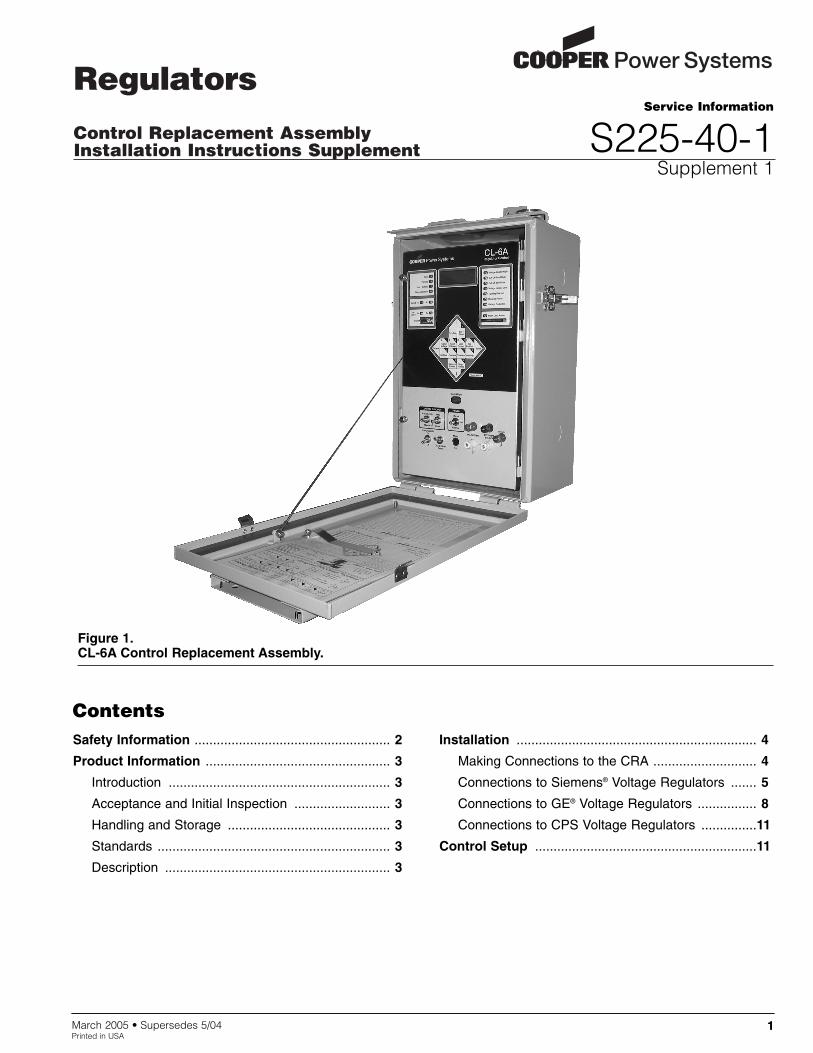
Figure 1.CL-6A Control Replacement Assembly.
1
Control Replacement Assembly Installation Instructions Supplement
2
The instructions in this manual are not intended as a sub-stitute for proper training or adequate experience in thesafe operation of the equipment described. Only compe-tent technicians, who are familiar with this equipmentshould install, operate, and service it.
A competent technician has these qualifications:
• Is thoroughly familiar with these instructions.
• Is trained in industry-accepted high- and low-voltagesafe operating practices and procedures.
• Is trained and authorized to energize, de-energize,clear, and ground power distribution equipment.
• Is trained in the care and use of protective equipmentsuch as flash clothing, safety glasses, face shield,hard hat, rubber gloves, hotstick, etc.
Following is important safety information. For safe instal-lation and operation of this equipment, be sure to readand understand all cautions and warnings.
Safety InstructionsFollowing are general caution and warning statementsthat apply to this equipment. Additional statements, relat-ed to specific tasks and procedures, are located through-out the manual.
SAFETY INFORMATION
WARNING: This equipment is not intended toprotect human life. Follow all locally approved pro-
cedures and safety practices when installing or operat-ing this equipment. Failure to comply can result indeath, severe personal injury and equipment damage.
G102.1
!
DANGER: Hazardous voltage. Contact withhazardous voltage will cause death or severe per-
sonal injury. Follow all locally approved safety proce-dures when working around high and low voltage linesand equipment. G103.3
!
WARNING: Before installing, operating, main-taining, or testing this equipment, carefully read
and understand the contents of this manual. Improperoperation, handling or maintenance can result in death,severe personal injury, and equipment damage. G101.0
!
SAFETY FOR LIFECooper Power Systems products meet or exceed all applicable industry standards relating to product safety. We activelypromote safe practices in the use and maintenance of our products through our service literature, instructional trainingprograms, and the continuous efforts of all Cooper Power Systems employees involved in product design, manufacture,marketing, and service.
We strongly urge that you always follow all locally approved safety procedures and safety instructions when workingaround high voltage lines and equipment and support our “Safety For Life” mission.
!SAFETYFOR LIFE
!SAFETYFOR LIFE
This manual may contain four types of hazard statements:
DANGER: Indicates an imminently haz-ardous situation which, if not avoided, will
result in death or serious injury.
WARNING: Indicates a potentially haz-ardous situation which, if not avoided, could
result in death or serious injury.
CAUTION: Indicates a potentially hazardoussituation which, if not avoided, may result in
minor or moderate injury.
CAUTION: Indicates a potentially hazardous situ-ation which, if not avoided, may result in equip-ment damage only.
!
!
!
Hazard Statement Definitions
WARNING: Power distribution equipment mustbe properly selected for the intended application.
It must be installed and serviced by competent person-nel who have been trained and understand propersafety procedures. These instructions are written forsuch personnel and are not a substitute for adequatetraining and experience in safety procedures. Failure toproperly select, install or maintain power distributionequipment can result in death, severe personal injury,and equipment damage. G122.2
!

IntroductionService Information S225-40-1 Supplement providesinstallation instructions for the CL-6A microprocessor-based voltage regulator control replacement assembly.This manual is intended to be used with ServiceInformation S225-40-1 McGraw-Edison® VoltageRegulator Control Replacement Assembly (CRA)Installation Instructions and Service Information. Beforeinstalling and operating this control, carefully read andunderstand the contents of this manual.
Refer to Service Information S225-11-1 VoltageRegulator CL-6 Series Control Installation, Operation,and Maintenance Instructions for information on the CL-6Series control.
Read This Manual FirstRead and understand the contents of this manual and fol-low all locally approved procedures and safety practicesbefore installing or operating this equipment. This controlis used in conjunction with a voltage regulator. Read andunderstand the appropriate voltage regulator instructionmanual before operating this control.
Additional InformationThese instructions cannot cover all details or variations inthe equipment, procedures, or process described norprovide directions for meeting every possible contin-gency during installation, operation, or maintenance. Foradditional information, please contact your CooperPower Systems representative.
Acceptance and InitialInspectionEach control replacement assembly is completelyassembled, tested, and inspected at the factory. It is ingood condition when accepted by the carrier for ship-ment. Upon receipt, inspect the shipping container forsigns of damage. Unpack the control and inspect it thor-oughly for damage incurred during shipment. If damageis discovered, file a claim with the carrier immediately.
Handling and StorageBe careful during handling and storage of the control tominimize the possibility of damage. If the control is to bestored for any length of time prior to installation, providea clean, dry storage area.
StandardsThe Cooper Power Systems voltage regulator controlsare designed and tested in accordance with:
IEEE Standard C57.15-1999™
IEEE Standard C57.95-1984™
Quality StandardsISO 9001:2000 Certified Quality Management System
DescriptionThe Cooper Power Systems Voltage Regulator ControlReplacement Assembly (CRA) is designed to be used onsingle-phase regulators manufactured by Siemens andGeneral Electric, as well as Cooper Power Systems typeVR32 voltage regulators.
The CRA utilizes the control signals common to all regu-lators and incorporates circuitry on non-CPS regulatorsto allow the proper interface between Cooper PowerSystems CL-series regulator controls and these regulators.
3
S225-40-1 Supplement!SAFETYFOR LIFE
PRODUCT INFORMATION
IMPORTANT: CRA Applications
The CRA was designed for used on General Electricand Siemens single-phase voltage regulators that uti-lize the following circuits:
• Control voltage or load-side voltage signal
• Motor raise and lower circuits
• Operations counter
• Common or ground
• CT current signal (optional)
• Source-side voltage signal (optional)
• Neutral light (optional)
• Drag hand reset (optional)
All of the signals listed are necessary for properoperation of the CRA unless otherwise noted asoptional.

Making Connections to the CRAThe CRA connections are made to terminal board TB1,located on the back-panel; see Figure 2. A color-codedwiring decal clearly identifies connections; see Figure 3.
Connecting the lead to the terminal board requires usingthe tool supplied with the CRA assembly or an accept-able substitute; see Figure 4.
To use the tool, place the tool in the square hole next tothe round hole where the proper wire is to be connected.Push the tool down, releasing the connector for the wire.Then, place the bare wire of the lead into the round hole,remove the tool from the square hole, and check the wireto make sure it is properly placed and is tight in the ter-minal board. Refer to Figure 5 for placement of the tooland the wire in the terminal board.
Control Replacement Assembly Installation Instructions Supplement
4
Figure 5.Connecting leads to terminal board.
INSTALLATION
Figure 4.Tool supplied for connecting leads.
Figure 2.CRA back panel.
Figure 3.Wiring identification decal.
Label
30 29 31
U12U11U10KJESiemensNLDHROCLRG
SOURCECONN.
V1V5V212HS G
CPSUNITONLY
Label
C. P. S.
G. E. 10 27 28
G RAISE LOWER OPCNTR DHRNEUT
LT HS 2 G 1 VRCT2 V5 VRCT
1
SOURCECONN. 26 or 10
EV4
REG. LOADFROM RCT 1
REG.SOURCE
FROM RCT 2
V4 C2
CT HIGHFOR
ACCESSORY
C2 C3
C3
CAUTION:DO NOTOPEN CTCIRCUITUNDERLOAD
White20AWG
JBB-C1JBB-C2
Black20AWG
C2
C
JBB-S2
2221
20,21 or 22
U2 P2
V120Knifeswitches - Top
V6
JBB-S4
32222120
G E. UNITONLYC. P. S.
G. E.
Siemens
Knifeswitches - BottomV6 V1 C
E1G E. UNIT
ONLY
Lead
Tool
TB1

Connections to Siemens® VoltageRegulators
The replacement procedure may be performed in theshop or the field. The regulator must be bypassed orremoved from service prior to installing the CRA. Alwaysbypass the regulator when installing the CRA in the fieldto prevent opening the CT circuit while the regulator isunder load.
Note: The control cable may be an actual cable or a flexibleconduit. For these instructions, it will be referred to as"control cable".
1. Bypass the regulator or remove it from service.
2. Open the existing control box and swing out the con-trol front panel. Remove the front panel by discon-necting the jack plug and lifting the control off of itshinges.
3. If the incoming control cable leads are not marked orcolor-coded, place appropriate wire markers on thecontrol cable leads or mark for reference later.
4. Disconnect the incoming control cable leads from thefemale jack plug located on the back of the controlbox.
If the tap-changer motor capacitor is located in thecontrol box, disconnect the leads from the capacitorand remove the capacitor for reinstallation in the CPSbox.
5. Remove the incoming control cable-retaining nut andremove the cable from the control box.
If the regulator is fitted with a non-flexible conduithousing the control leads, it will be necessary to mod-ify or replace this conduit with a flexible conduit toallow interface to the Cooper Power Systems box.
6. Remove the cable compression connector (cablegrip) from the control box.
7. Remove the nameplate from the old control boxassembly and retain, with the hardware.
8. With an adjustable wrench (or appropriate socketwrench), remove and retain the bolts holding the con-trol box on the regulator.
9. Remove the old control box assembly from the regu-lator.
10. Place the supplied universal bracket over the mount-ing bosses of the regulator and secure with boltsretained from the existing regulator.
11. Place the CRA control box on the universal bracketand secure it to the regulator with bolt, washer, lock-washer, and nut provided.
12. Attach the nameplate to the front of the CRA controlbox with retained hardware.
13. Ground the control cabinet via the ground boss locat-ed on the side of the cabinet.
14. Examine the control cable. Allow approximately 12" oflead length to protrude past the end of the conduitnut. This will facilitate connection to the top terminalstrip and knife switches located in the box.
15. Remove the cable grip nut and rubber cable grommetfrom the cable entrance of the control box.
16. Place the cable grip nut over the competitors controlcable. Select, from the two supplied rubber cablegrommets, the one that fits the competitor’s cable;place grommet onto the control cable.
17. Cut the terminals off of the customers control cableconductors.
If the competitors controls had a capacitor in the con-trol cabinet, leave the capacitor connection terminalson the wires for the capacitor.
18. Strip the insulation back approximately 5/16 of aninch on each lead that is to connect to TB1 andswitches.
19. Insert the control cable into the control-box cable gripconnector, seating the rubber grommet, and tightenthe cable grip nut.
5
S225-40-1 Supplement!SAFETYFOR LIFE
WARNING: Flashover Hazard. Opening theC.T. circuit under load will produce high voltages
in the control box. Always bypass the regulator wheninstalling the CRA to prevent opening the C.T. circuitwhile the regulator is under load. Failure to comply canresult in severe personal injury or death. VR-T215.0
!
DANGER: Explosion Hazard. Voltage regula-tors are subject to high circulating current dur-
ing bypass switching. Refer to Service InformationS225-11-1 Voltage Regulator CL-6 Series ControlInstallation, Operation, and Maintenance Instructionsfor information on the CRA Control, and refer to theinstruction manual supplied by the voltage regulatormanufacturer for specific safety procedures for bypassswitching. Failure to comply will result in severe per-sonal injury or death. VR-T214.0
!
WARNING: Hazardous Voltage. The controlbox must be solidly earth grounded. Failure to
comply can result in severe personal injury and equip-ment damage. VR-T216.0
!
20. V6 connections and source-side signal.
Note: If there is only one RCT on the back panel, it is rec-ommended to let the control calculate the source-side signal by making the necessary connectionsas described in step B.
A. If the regulator has a source-side control signalpresent and the back panel has two RCTs OR ifthe source-side supply is excitedly 120 V, thewhite/brown Number 23 lead can stay connectedto the bottom of V6 (as shown in Figure 7) and theinternal source-side supply can be used forreverse power flow operation.
B. If there is no source-side control signal, OR onlyone RCT on the back panel, OR two RCTs on theback panel and you want to support control calcu-lation of the source-side signal for reverse powerflow operation, follow these wiring steps:
1. Connect the Siemens U2 lead, if present, tothe top of the V6 switch.
2. Using the supplied tool or a proper substitute,remove the white/brown Number 23 lead fromthe bottom section of V6 and place, with theNumber 17 lead, at the bottom of V1.
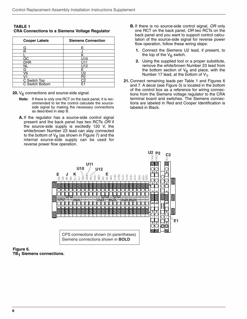
21. Connect remaining leads per Table 1 and Figures 6and 7. A decal (see Figure 3) is located in the bottomof the control box as a reference for wiring connec-tions from the Siemens voltage regulator to the CRAterminal board and switches. The Siemens connec-tions are labeled in Red and Cooper Identification islabeled in Black.
Control Replacement Assembly Installation Instructions Supplement
6
Cooper Labels Siemens Connection
G ER JL KOC U10DHR U11 NL U12G EV6 U2V1 P2C Switch Top C2C Switch Bottom E1
TABLE 1CRA Connections to a Siemens Voltage Regulator
Figure 6.TB1 Siemens connections.
CPS connections shown (in parentheses)Siemens connections shown in BOLD
EU10 U12
E
E1
U2 P2 C2
U11
KJ

7
S225-40-1 Supplement!SAFETYFOR LIFE
Figure 7.CRA back panel wiring to Siemens voltage regulator.
30
27
25
23
21
20
120
RCT1
13
1 2 3 4 5 6 7
G HSNLDHR
R L 20V5 V4V1#1#2
10
C3G TB1
1513
18
18 205 29
25
12
19
2712964 72 828 3
TB8
G R L V2G
11
C2
23 16
96315
19
20
2722 8414TB2
DHRNLHS L3R3C3C1VMVSV7V9 GBRJ5678 G VS
11
22
175
C
1423
17
COM
1
OC 21 22
2
V1V6
25
7
28
29
OC
30
36
31
37
35
34
33
32
10
White EBlack J Brown U10
Yellow E1
Orange C2
Blue P2
Green U12Violet U12Grey U11Red K
Siemens Wiring Connections
Wire Color Code
1 White2 White3 Orange4 Blue5 Blue6 White/Green7 White/Green8 White/Red9 White/Orange10 Black11 Black12 White13 Violet14 Green15 Red16 Red17 Black18 White19 White20 White/Blue21 White/Brown22 White23 White/Brown24 White25 Black26 White/Brown27 Brown28 Brown29 Red/Black30 Blue31 Green32 Yellow33 Orange34 Red35 Brown36 Black37 White
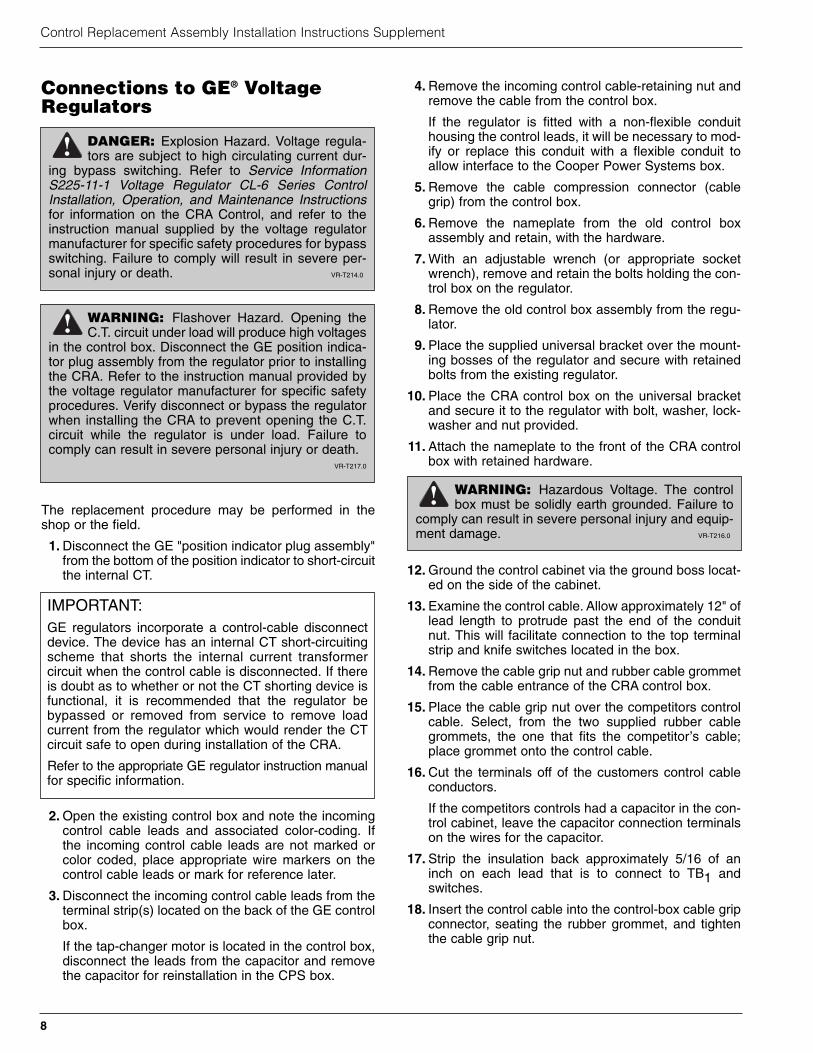
Connections to GE® VoltageRegulators
The replacement procedure may be performed in theshop or the field.
1. Disconnect the GE "position indicator plug assembly"from the bottom of the position indicator to short-circuitthe internal CT.
2. Open the existing control box and note the incomingcontrol cable leads and associated color-coding. Ifthe incoming control cable leads are not marked orcolor coded, place appropriate wire markers on thecontrol cable leads or mark for reference later.
3. Disconnect the incoming control cable leads from theterminal strip(s) located on the back of the GE controlbox.
If the tap-changer motor is located in the control box,disconnect the leads from the capacitor and removethe capacitor for reinstallation in the CPS box.
4. Remove the incoming control cable-retaining nut andremove the cable from the control box.
If the regulator is fitted with a non-flexible conduithousing the control leads, it will be necessary to mod-ify or replace this conduit with a flexible conduit toallow interface to the Cooper Power Systems box.
5. Remove the cable compression connector (cablegrip) from the control box.
6. Remove the nameplate from the old control boxassembly and retain, with the hardware.
7. With an adjustable wrench (or appropriate socketwrench), remove and retain the bolts holding the con-trol box on the regulator.
8. Remove the old control box assembly from the regu-lator.
9. Place the supplied universal bracket over the mount-ing bosses of the regulator and secure with retainedbolts from the existing regulator.
10. Place the CRA control box on the universal bracketand secure it to the regulator with bolt, washer, lock-washer and nut provided.
11. Attach the nameplate to the front of the CRA controlbox with retained hardware.
12. Ground the control cabinet via the ground boss locat-ed on the side of the cabinet.
13. Examine the control cable. Allow approximately 12" oflead length to protrude past the end of the conduitnut. This will facilitate connection to the top terminalstrip and knife switches located in the box.
14. Remove the cable grip nut and rubber cable grommetfrom the cable entrance of the CRA control box.
15. Place the cable grip nut over the competitors controlcable. Select, from the two supplied rubber cablegrommets, the one that fits the competitor’s cable;place grommet onto the control cable.
16. Cut the terminals off of the customers control cableconductors.
If the competitors controls had a capacitor in the con-trol cabinet, leave the capacitor connection terminalson the wires for the capacitor.
17. Strip the insulation back approximately 5/16 of aninch on each lead that is to connect to TB1 andswitches.
18. Insert the control cable into the control-box cable gripconnector, seating the rubber grommet, and tightenthe cable grip nut.
Control Replacement Assembly Installation Instructions Supplement
8
WARNING: Flashover Hazard. Opening theC.T. circuit under load will produce high voltages
in the control box. Disconnect the GE position indica-tor plug assembly from the regulator prior to installingthe CRA. Refer to the instruction manual provided bythe voltage regulator manufacturer for specific safetyprocedures. Verify disconnect or bypass the regulatorwhen installing the CRA to prevent opening the C.T.circuit while the regulator is under load. Failure tocomply can result in severe personal injury or death.
VR-T217.0
!
DANGER: Explosion Hazard. Voltage regula-tors are subject to high circulating current dur-
ing bypass switching. Refer to Service InformationS225-11-1 Voltage Regulator CL-6 Series ControlInstallation, Operation, and Maintenance Instructionsfor information on the CRA Control, and refer to theinstruction manual supplied by the voltage regulatormanufacturer for specific safety procedures for bypassswitching. Failure to comply will result in severe per-sonal injury or death. VR-T214.0
!
WARNING: Hazardous Voltage. The controlbox must be solidly earth grounded. Failure to
comply can result in severe personal injury and equip-ment damage. VR-T216.0
!
IMPORTANT:GE regulators incorporate a control-cable disconnectdevice. The device has an internal CT short-circuitingscheme that shorts the internal current transformercircuit when the control cable is disconnected. If thereis doubt as to whether or not the CT shorting device isfunctional, it is recommended that the regulator bebypassed or removed from service to remove loadcurrent from the regulator which would render the CTcircuit safe to open during installation of the CRA.
Refer to the appropriate GE regulator instruction manualfor specific information.
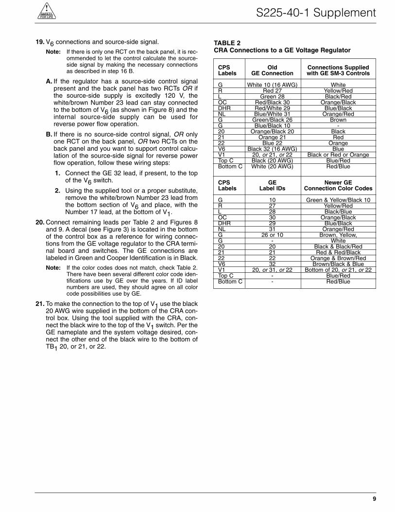
19. V6 connections and source-side signal.
Note: If there is only one RCT on the back panel, it is rec-ommended to let the control calculate the source-side signal by making the necessary connectionsas described in step 16 B.
A. If the regulator has a source-side control signalpresent and the back panel has two RCTs OR ifthe source-side supply is excitedly 120 V, thewhite/brown Number 23 lead can stay connectedto the bottom of V6 (as shown in Figure 8) and theinternal source-side supply can be used forreverse power flow operation.
B. If there is no source-side control signal, OR onlyone RCT on the back panel, OR two RCTs on theback panel and you want to support control calcu-lation of the source-side signal for reverse powerflow operation, follow these wiring steps:
1. Connect the GE 32 lead, if present, to the topof the V6 switch.
2. Using the supplied tool or a proper substitute,remove the white/brown Number 23 lead fromthe bottom section of V6 and place, with theNumber 17 lead, at the bottom of V1.
20. Connect remaining leads per Table 2 and Figures 8and 9. A decal (see Figure 3) is located in the bottomof the control box as a reference for wiring connec-tions from the GE voltage regulator to the CRA termi-nal board and switches. The GE connections arelabeled in Green and Cooper Identification is in Black.
Note: If the color codes does not match, check Table 2.There have been several different color code iden-tifications use by GE over the years. If ID labelnumbers are used, they should agree on all colorcode possibilities use by GE.
21. To make the connection to the top of V1 use the black20 AWG wire supplied in the bottom of the CRA con-trol box. Using the tool supplied with the CRA, con-nect the black wire to the top of the V1 switch. Per theGE nameplate and the system voltage desired, con-nect the other end of the black wire to the bottom ofTB1 20, or 21, or 22.
9
S225-40-1 Supplement!SAFETYFOR LIFE
CPS Old Connections SuppliedLabels GE Connection with GE SM-3 Controls
G White 10 (16 AWG) WhiteR Red 27 Yellow/RedL Green 28 Black/RedOC Red/Black 30 Orange/BlackDHR Red/White 29 Blue/BlackNL Blue/White 31 Orange/RedG Green/Black 26 BrownG Blue/Black 10 -20 Orange/Black 20 Black21 Orange 21 Red22 Blue 22 OrangeV6 Black 32 (16 AWG) BlueV1 20, or 21, or 22 Black or Red or OrangeTop C Black (20 AWG) Blue/RedBottom C White (20 AWG) Red/Blue
CPS GE Newer GELabels Label IDs Connection Color Codes
G 10 Green & Yellow/Black 10R 27 Yellow/RedL 28 Black/BlueOC 30 Orange/BlackDHR 29 Blue/BlackNL 31 Orange/RedG 26 or 10 Brown, Yellow, G - White20 20 Black & Black/Red21 21 Red & Red/Black22 22 Orange & Brown/RedV6 32 Brown/Black & BlueV1 20, or 31, or 22 Bottom of 20, or 21, or 22Top C - Blue/RedBottom C - Red/Blue
TABLE 2CRA Connections to a GE Voltage Regulator
Control Replacement Assembly Installation Instructions Supplement
10
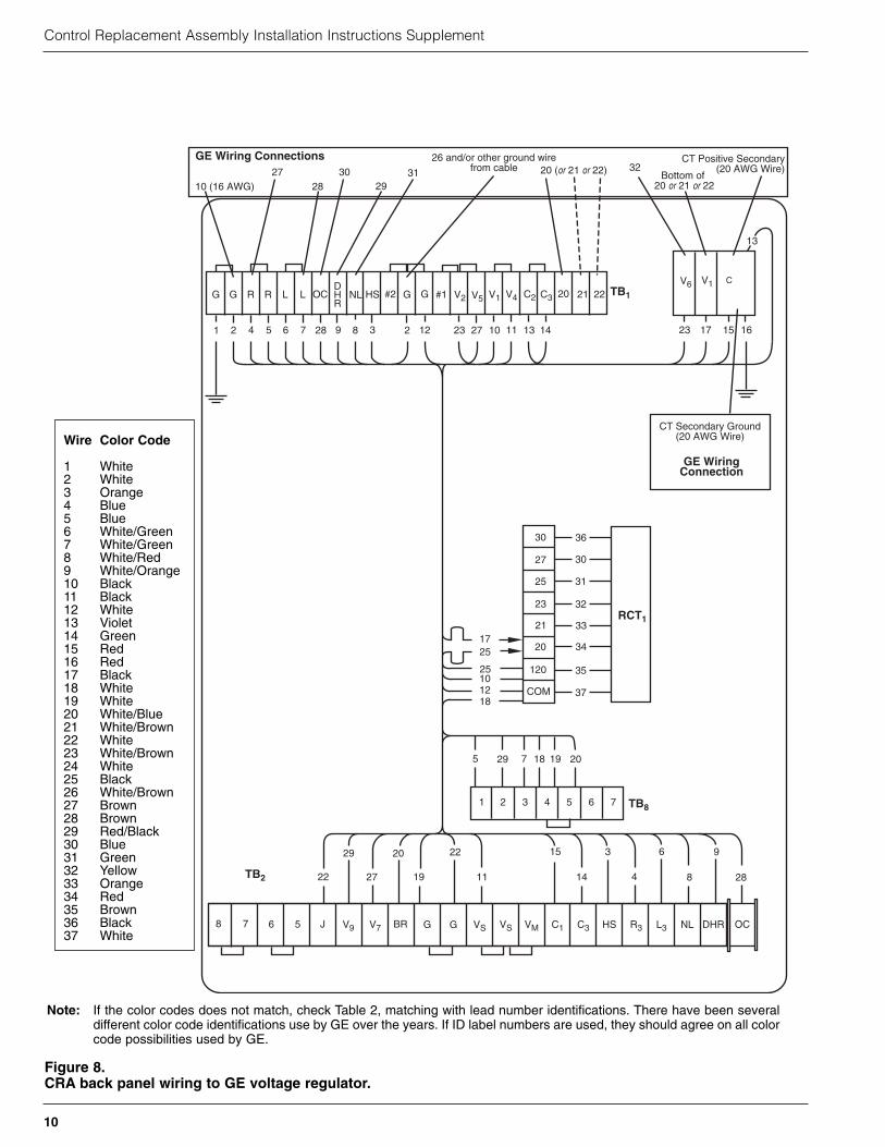
Figure 8.CRA back panel wiring to GE voltage regulator.
30
27
25
23
21
20
120
RCT1
13
1 2 3 4 5 6 7
G HSNLDHR
R L 20V5 V4V1#1#2
10
C3G TB1
1513
18
18 205 29
25
12
19
2712964 72 828 3
TB8
G R L V2G
11
C2
23 16
96315
19
20
2722 8414TB2
DHRNLHS L3R3C3C1VMVSV7V9 GBRJ5678 G VS
11
22
175
C
1423
17
COM
1
OC 21 22
2
V1V6
25
7
28
29
OC
30
36
31
37
35
34
33
32
10
10 (16 AWG)27 30
CT Positive Secondary(20 AWG Wire)
Bottom of 20 or 21 or 22
32312928
26 and/or other ground wirefrom cable 20 (or 21 or 22)
CT Secondary Ground(20 AWG Wire)
GE Wiring Connections
GE WiringConnection
Wire Color Code
1 White2 White3 Orange4 Blue5 Blue6 White/Green7 White/Green8 White/Red9 White/Orange10 Black11 Black12 White13 Violet14 Green15 Red16 Red17 Black18 White19 White20 White/Blue21 White/Brown22 White23 White/Brown24 White25 Black26 White/Brown27 Brown28 Brown29 Red/Black30 Blue31 Green32 Yellow33 Orange34 Red35 Brown36 Black37 White
Note: If the color codes does not match, check Table 2, matching with lead number identifications. There have been severaldifferent color code identifications use by GE over the years. If ID label numbers are used, they should agree on all colorcode possibilities used by GE.
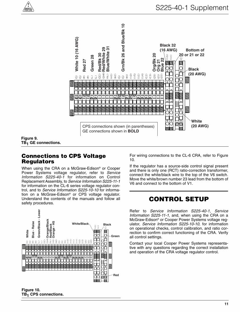
Connections to CPS VoltageRegulatorsWhen using the CRA on a McGraw-Edison® or CooperPower Systems voltage regulator, refer to ServiceInformation S225-40-1 for information on ControlReplacement Assembly, to Service Information S225-11-1for information on the CL-6 series voltage regulator con-trol, and to Service Information S225-10-10 for informa-tion on a McGraw-Edison® or CPS voltage regulator.Understand the contents of the manuals and follow allsafety procedures.
For wiring connections to the CL-6 CRA, refer to Figure10.
If the regulator has a source-side control signal presentand there is only one (RCT) ratio-correction transformer,connect the white/black wire to the top of the V6 switch.Move the white/brown number 23 lead from the bottom ofV6 and connect to the bottom of V1.
CONTROL SETUP
Refer to Service Information S225-40-1, ServiceInformation S225-11-1, and, when using the CRA on aMcGraw-Edison® or Cooper Power Systems voltage reg-ulator, Service Information S225-10-10, for informationon operational checks, control calibration, and ratio cor-rection to confirm correct functioning of the CRA. Verifyall control settings.
Contact your local Cooper Power Systems representa-tive with any questions regarding the correct installationand operation of the CRA voltage regulator control.
11
S225-40-1 Supplement!SAFETYFOR LIFE
Figure 9.TB1 GE connections.
CPS connections shown (in parentheses)GE connections shown in BOLD
Wh
ite
10 (
16 A
WG
)
Black 32(16 AWG)
Blu
e 22
Org
21
Org
/Bk
20
Grn
/Bk
26 a
nd
Blu
e/B
k 10
Blu
e/W
hit
e 31
Red
/Wh
ite
29R
ed/B
k 30
Gre
en 2
8
Red
27
White(20 AWG)
Bottom of20 or 21 or 22
Black(20 AWG)
Figure 10.TB1 CPS connections.
Wh
ite
White/Black
Red
/Bla
ckO
ran
ge/
Bla
ck
Ora
ng
e -
HS
Gre
en/B
lack
- L
ow
er
Blu
e -
Rai
se
Red
Black
Green
Control Replacement Assembly Installation Instructions Supplement
DL3/05
©2005 Cooper Power Systems or its affiliates.McGraw-Edison® is a registered trademark of Cooper Power Systemsor its affiliates.IEEE Standard C57.15-1999™ and IEEE Standard C57.95-1984™ aretrademarks of the Institute of Electrical and Electronics Engineers, Inc.GE® is a registered trademark of General Electric Company.Siemens® is a registered trademark of Siemens Aktiengesellschaft.
1045 Hickory StreetPewaukee, WI 53072 USAwww.cooperpower.com
!SAFETYFOR LIFE