service bulletin summary
TRANSCRIPT

SPECIAL CHECK – FRONT AND REAR ENGINE MOUNT ASSEMBLIES –INSPECTION OF BUSHINGS ON THE ENGINE MOUNT SYSTEM
The information below is provided for your reference. For full details, including labor and partcoverage, please see corresponding paragraph contained within this bulletin.
RECOMMENDEDSPECIFIED TIME COMPLIANCE
COMPLIANCE TIME
Refer to Paragraph 1.D.
EFFECTIVITY: A/C Serial No. 9313, 9381, 9432 to 9860, 9863 to 9871, 9873 to 9879,60005 and 60024
MANPOWER: Refer to Paragraph 1.F.
CONTINUED AIRWORTHINESS (CAW)FLEET CAMPAIGN NOYES
TLMC, CH 5 AFFECTED NOYES
KITS and/or PARTS NOYES
TOOLING/GSE YES NO
PLANNING INFORMATION NOYES
DEDICATED SCHEDULE NOYES
PREREQUISITE SERVICE BULLETINS: N/A
NOTE: This Service Bulletin may be subject to an Airworthiness Directive which will makeit necessary to implement this Service Bulletin.
To place an order for parts or kits, please call Bombardier Aviation Parts Services at:
514−855−2999 or 1−866−538−1247
SERVICE BULLETIN SUMMARYmy.businessaircraft.bombardier.com
MODEL BD−700−1A10 (BD−700)
ATA 71−23, 71−24
POWERPLANT
Basic Issue: Dec 14/2020 700−71−6005Page 1 of 1
This Service Bulletin is available at:
SPECIAL CHECK – FRONT AND REAR ENGINE MOUNT ASSEMBLIES –INSPECTION OF BUSHINGS ON THE ENGINE MOUNT SYSTEM
1. PLANNING INFORMATION
NOTE: Before you do this Service Bulletin, examine all STC, STA or equivalentaction changes to make sure that this Service Bulletin can be completed.
A. Effectivity
BD−700−1A10 aircraft, Serial No. 9313, 9381, 9432 to 9860, 9863 to 9871, 9873 to9879, 60005 and 60024.
NOTE: The instructions given in this Service Bulletin are only applicable to thesystems and parts installed at the time of delivery of the aircraft or aschanged by Bombardier Aviation Service Bulletin(s).
B. Reason
1. Evidence:
There have been reports that bushings were missing from the forward enginemount system.
2. Objective/Benefit:
This Service Bulletin instructs to inspect the forward and aft engine mountsystem for missing bushings and to verify the proper installation of the slidingbushings. Continued operation of engine with bushings missing will result inredistribution of load/stress in the engine mount system and may lead to thedamage of mount components.
SERVICE BULLETINmy.businessaircraft.bombardier.com
MODEL BD−700−1A10 (BD−700)
ATA 71−23, 71−24
POWERPLANT
Refer to applicable governmental agency regulations and requirements and make sure that the work described in thisService Bulletin is performed in compliance with manufacturer’s recommendations and/or acceptable industry standards.
This document is proprietary to Bombardier Inc. and/or its affiliates and may not be reproduced or copied in any form orby any means without the prior written consent of Bombardier Inc. and/or its affiliates.
2020 Bombardier Inc. All rights reservedLearjet, Challenger, Global, are registered trademarks of Bombardier Inc. or its subsidiaries.
Basic Issue: Dec 14/2020 700−71−6005Page 1 of 26
This Service Bulletin is available at:

C. Description
This Service Bulletin gives instructions in PART A to:
− Inspect at the upper and lower side of front mount beam for proper installation ofsliding bushing, Part No. BRR15811.
This Service Bulletin gives instructions in PART B to:
− Inspect at the thrust strut front location for proper installation of sliding bushing,Part No. BRR15808.
This Service Bulletin gives instructions in PART C to:
− Inspect at the thrust strut aircraft pylon interface for proper installation of slidingbushing, Part No. BRR15823.
This Service Bulletin gives instructions in PART D to:
− Inspect at the front mount beam interface with the aircraft pylon upper and lowerinstallation for proper installation of sliding bushing, Part No. BRR15804.
This Service Bulletin gives instructions in PART E to:
− Inspect at the rear mount beam interface with the aircraft pylon upper and lowerinstallation for proper installation of sliding bushing, Part No. BRR15841.
D. Compliance
Recommended in less than 750 flight hours or 15 months, whichever comes firstfrom this Service Bulletin release date (Basic Issue).
NOTE: If it is not possible to complete all the instructions in this Service Bulletinbecause of the aircraft configuration, submit an SRPSA for analysis and toget an approved disposition to complete this Service Bulletin.
E. Approval
The technical content of this Service Bulletin has been approved under theauthority of Transport Canada Civil Aviation (TCCA) Design Approval Organization(DAO) No. DAO #93−Q−02.
NOTES: 1. The technical content of this Service Bulletin is accepted by the FAAunder the Canada/USA bilateral Aviation Safety Agreement.
2. The technical content of this Service Bulletin is accepted by EASAunder the Canada/EU bilateral Aviation Safety Agreement.
MODEL BD−700−1A10 (BD−700)
Basic Issue: Dec 14/2020 700−71−6005Page 2 of 26

F. Manpower
NOTES: 1. The man−hours given are to help you schedule the tasks given in thisService Bulletin. The man−hours are for direct labor performed by anexperienced crew and do not include the time for familiarization,planning, aircraft preparation in hangar such as towing andpositioning of scaffolds, removal of interior furnishings, repainting,supervision and inspection.
For more information related to the manpower, refer toSB 700−00−6002.
2. This Service Bulletin may require consumable materials that havespecific curing times (refer to Paragraph 3). The accumulated curingtime is not included in the man−hours and should be considered forplanning purposes before you schedule this Service Bulletin
10.5 man−hours are necessary to do this Service Bulletin.
The labor required to do this Service Bulletin is at no cost if:
− the work is done during new aircraft warranty period, and
− the work is done at Bombardier Business Aviation Services (BBAS) orAuthorized Service Facilities (ASF), and
− this Service Bulletin is scheduled in less than 750 flight hours or 15 months,whichever comes first, from its release date (Basic Issue).
G. Material − Cost and Availability
No kit or parts are necessary to do this Service Bulletin.
H. Tooling
The equipment and tools listed below are necessary to do this modification:
GSE REFERENCE NO. PART NO. DESCRIPTION
20X−10−01 S4933959−501 Tag, Circuit Breaker (RedRing)
71X−13−02 G700−711302−1 Protective Mats − LowerEngine Cowl
Commercially available − Feeler Gauge
Commercially available − Wrench, Torque 125 to250 lbf in (14.13 to 28.24
Nm)
NOTES: 1. Refer to the Global 6000 Illustrated Tool and Equipment Manual(ITEM) to make sure that you use the correct equipmentconfiguration.
MODEL BD−700−1A10 (BD−700)
Basic Issue: Dec 14/2020 700−71−6005Page 3 of 26

2. Refer to the Liability Statement in the ITEM for the G6000 foracceptable GSE equivalents.
3. This list is provided for quick reference. In case of discrepancybetween this list and the tools called in the SPM, WM, Chapter 20,then the tools called in the SPM, WM prevail. Other approvedalternative tools are acceptable and can also be used.
I. Weight and Balance
No change.
J. Electrical Load Data
No change.
K. References
− TCCA Airworthiness Directive (Pending).
− Bombardier Aviation, Restriction and/or Special Instruction (RSI), C−01793,Rev. −−.
− Rolls Royce, Engine Maintenance Manual (EMM), Chapters 70 and 71.
− Global 6000 BD−700 Aircraft Maintenance Manual (AMM), Chapters 6, 24, 71and 78.
− Global 6000 BD−700 Illustrated Tool and Equipment Manual (ITEM), Chapters20 and 71.
L. Other Publications Affected
None.
M. Equivalent Service Bulletins
− For the Global Express and Global Express XRS BD−700−1A10 aircraft, useService Bulletin 700−71−005.
− For the Global 5000 BD−700−1A11 aircraft, use ServiceBulletin 700−1A11−71−005.
− For the Global 5000 BD−700−1A11 Featuring Global Vision Flight Deck aircraft,use Service Bulletin 700−71−5005.
− For the Global 5500 BD−700−1A11 aircraft, use Service Bulletin 700−71−5501.
− For the Global 6500 BD−700−1A10 aircraft, use Service Bulletin 700−71−6501.
MODEL BD−700−1A10 (BD−700)
Basic Issue: Dec 14/2020 700−71−6005Page 4 of 26
2. ACCOMPLISHMENT INSTRUCTIONS
NOTES: 1. All TASKs given in the procedures that follow are from the Global 6000BD−700−1A10 Aircraft Maintenance Manual (AMM) unless otherwisespecified.
2. All references made to zones, access panels and/or doors, are from theGlobal 6000 BD−700−1A10 Aircraft Maintenance Manual (AMM),Chapter 6.
A. Aircraft Setup
NOTE: The steps in the Aircraft Setup section of this Service Bulletin arerecommended steps. The steps give a recommendation to get access tothe work area. This recommendation is to give a safe work area and tominimize possible damage to surrounding aircraft parts. Alternative stepscan be used at the operator’s discretion.
(1) Obey all electrical/electronic safety precautions. Refer toAMM 24−00−00−910−801.
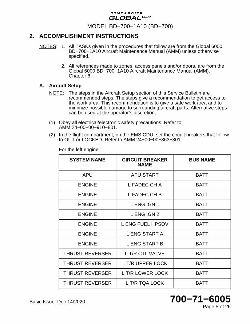
(2) In the flight compartment, on the EMS CDU, set the circuit breakers that followto OUT or LOCKED. Refer to AMM 24−00−00−863−801:
For the left engine:
SYSTEM NAME CIRCUIT BREAKERNAME
BUS NAME
APU APU START BATT
ENGINE L FADEC CH A BATT
ENGINE L FADEC CH B BATT
ENGINE L ENG IGN 1 BATT
ENGINE L ENG IGN 2 BATT
ENGINE L ENG FUEL HPSOV BATT
ENGINE L ENG START A BATT
ENGINE L ENG START B BATT
THRUST REVERSER L T/R CTL VALVE BATT
THRUST REVERSER L T/R UPPER LOCK BATT
THRUST REVERSER L T/R LOWER LOCK BATT
THRUST REVERSER L T/R TQA LOCK BATT
MODEL BD−700−1A10 (BD−700)
Basic Issue: Dec 14/2020 700−71−6005Page 5 of 26
SYSTEM NAME CIRCUIT BREAKERNAME
BUS NAME
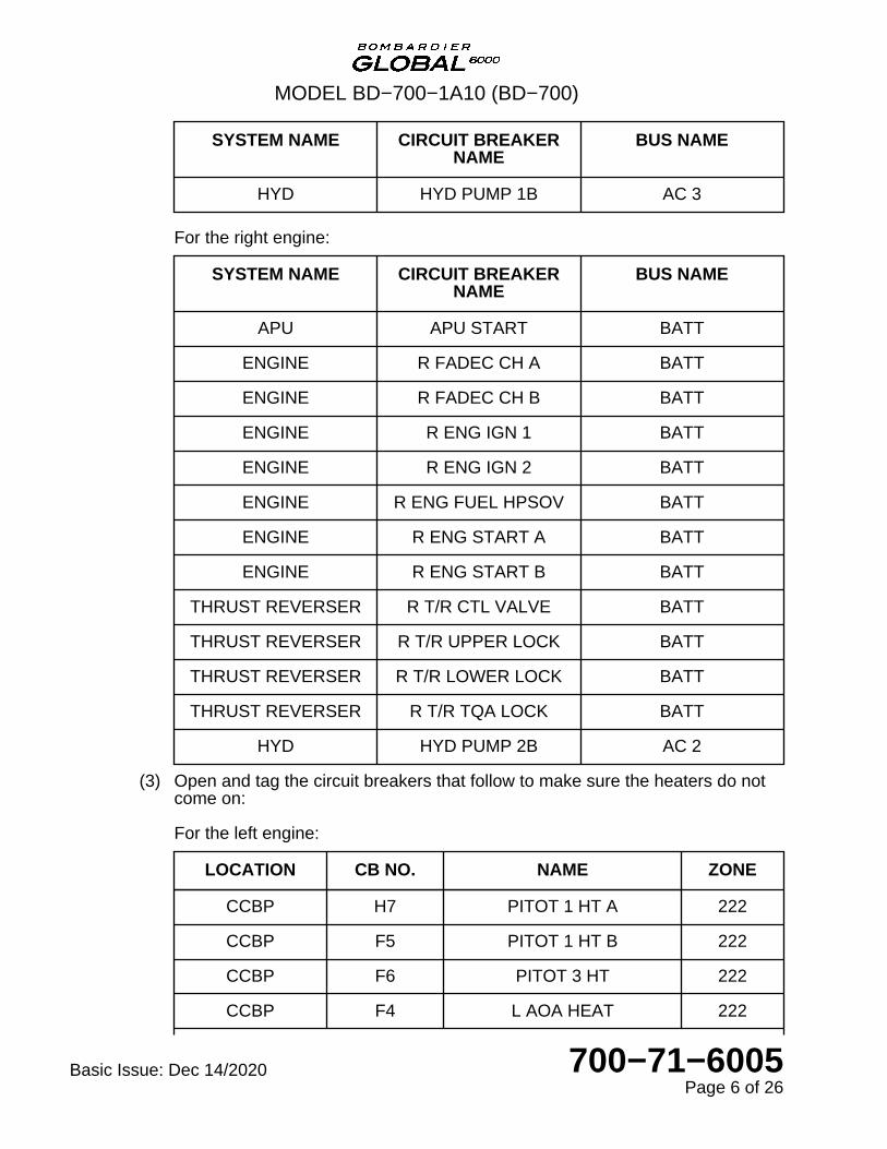
HYD HYD PUMP 1B AC 3
For the right engine:
SYSTEM NAME CIRCUIT BREAKERNAME
BUS NAME
APU APU START BATT
ENGINE R FADEC CH A BATT
ENGINE R FADEC CH B BATT
ENGINE R ENG IGN 1 BATT
ENGINE R ENG IGN 2 BATT
ENGINE R ENG FUEL HPSOV BATT
ENGINE R ENG START A BATT
ENGINE R ENG START B BATT
THRUST REVERSER R T/R CTL VALVE BATT
THRUST REVERSER R T/R UPPER LOCK BATT
THRUST REVERSER R T/R LOWER LOCK BATT
THRUST REVERSER R T/R TQA LOCK BATT
HYD HYD PUMP 2B AC 2
(3) Open and tag the circuit breakers that follow to make sure the heaters do notcome on:
For the left engine:
LOCATION CB NO. NAME ZONE
CCBP H7 PITOT 1 HT A 222
CCBP F5 PITOT 1 HT B 222
CCBP F6 PITOT 3 HT 222
CCBP F4 L AOA HEAT 222
MODEL BD−700−1A10 (BD−700)
Basic Issue: Dec 14/2020 700−71−6005Page 6 of 26
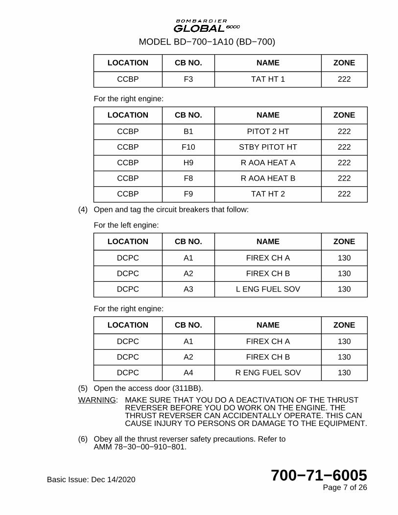
LOCATION CB NO. NAME ZONE
CCBP F3 TAT HT 1 222
For the right engine:
LOCATION CB NO. NAME ZONE
CCBP B1 PITOT 2 HT 222
CCBP F10 STBY PITOT HT 222
CCBP H9 R AOA HEAT A 222
CCBP F8 R AOA HEAT B 222
CCBP F9 TAT HT 2 222
(4) Open and tag the circuit breakers that follow:
For the left engine:
LOCATION CB NO. NAME ZONE
DCPC A1 FIREX CH A 130
DCPC A2 FIREX CH B 130
DCPC A3 L ENG FUEL SOV 130
For the right engine:
LOCATION CB NO. NAME ZONE
DCPC A1 FIREX CH A 130
DCPC A2 FIREX CH B 130
DCPC A4 R ENG FUEL SOV 130
(5) Open the access door (311BB).
WARNING: MAKE SURE THAT YOU DO A DEACTIVATION OF THE THRUSTREVERSER BEFORE YOU DO WORK ON THE ENGINE. THETHRUST REVERSER CAN ACCIDENTALLY OPERATE. THIS CANCAUSE INJURY TO PERSONS OR DAMAGE TO THE EQUIPMENT.
(6) Obey all the thrust reverser safety precautions. Refer toAMM 78−30−00−910−801.
MODEL BD−700−1A10 (BD−700)
Basic Issue: Dec 14/2020 700−71−6005Page 7 of 26
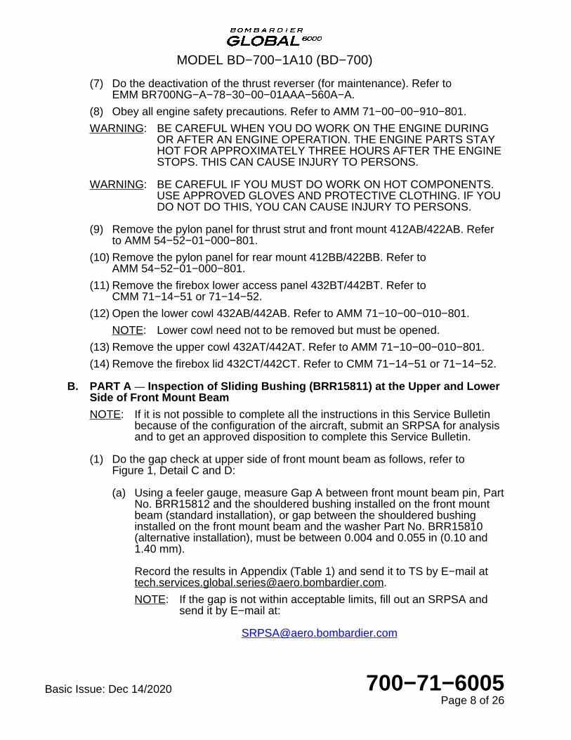
(7) Do the deactivation of the thrust reverser (for maintenance). Refer toEMM BR700NG−A−78−30−00−01AAA−560A−A.
(8) Obey all engine safety precautions. Refer to AMM 71−00−00−910−801.
WARNING: BE CAREFUL WHEN YOU DO WORK ON THE ENGINE DURINGOR AFTER AN ENGINE OPERATION. THE ENGINE PARTS STAYHOT FOR APPROXIMATELY THREE HOURS AFTER THE ENGINESTOPS. THIS CAN CAUSE INJURY TO PERSONS.
WARNING: BE CAREFUL IF YOU MUST DO WORK ON HOT COMPONENTS.USE APPROVED GLOVES AND PROTECTIVE CLOTHING. IF YOUDO NOT DO THIS, YOU CAN CAUSE INJURY TO PERSONS.
(9) Remove the pylon panel for thrust strut and front mount 412AB/422AB. Referto AMM 54−52−01−000−801.
(10) Remove the pylon panel for rear mount 412BB/422BB. Refer toAMM 54−52−01−000−801.
(11) Remove the firebox lower access panel 432BT/442BT. Refer toCMM 71−14−51 or 71−14−52.
(12) Open the lower cowl 432AB/442AB. Refer to AMM 71−10−00−010−801.
NOTE: Lower cowl need not to be removed but must be opened.
(13) Remove the upper cowl 432AT/442AT. Refer to AMM 71−10−00−010−801.
(14) Remove the firebox lid 432CT/442CT. Refer to CMM 71−14−51 or 71−14−52.
B. PART A — Inspection of Sliding Bushing (BRR15811) at the Upper and LowerSide of Front Mount Beam
NOTE: If it is not possible to complete all the instructions in this Service Bulletinbecause of the configuration of the aircraft, submit an SRPSA for analysisand to get an approved disposition to complete this Service Bulletin.
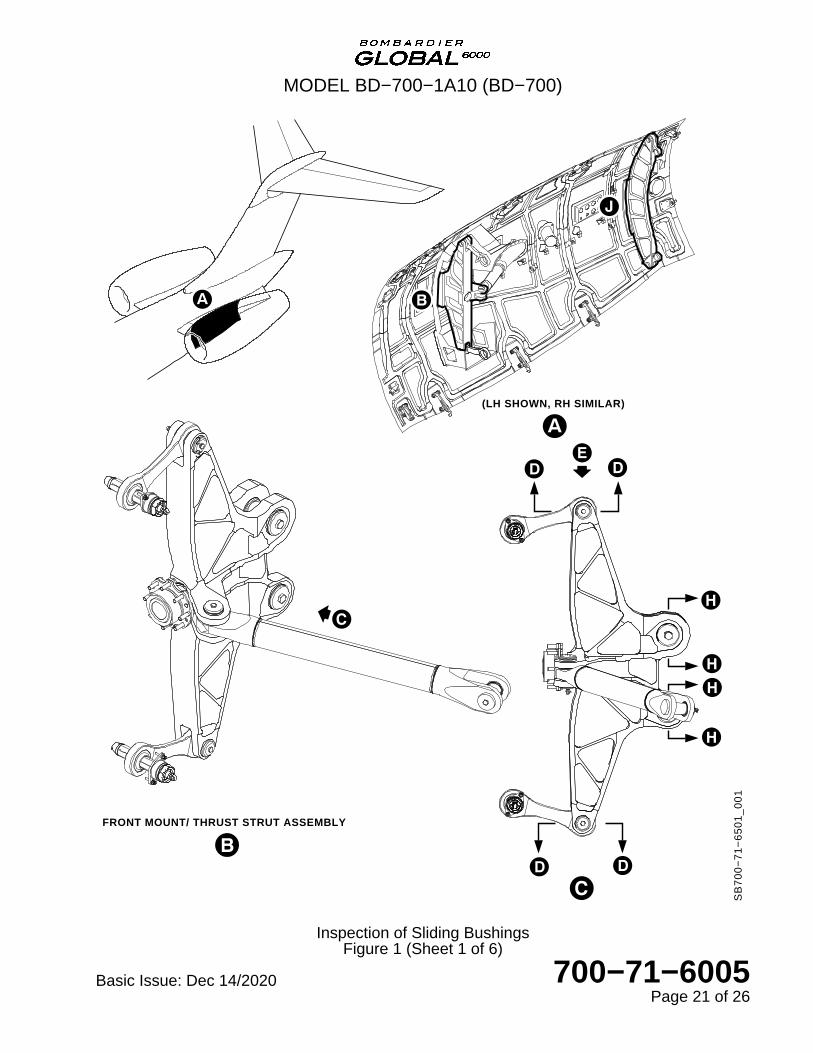
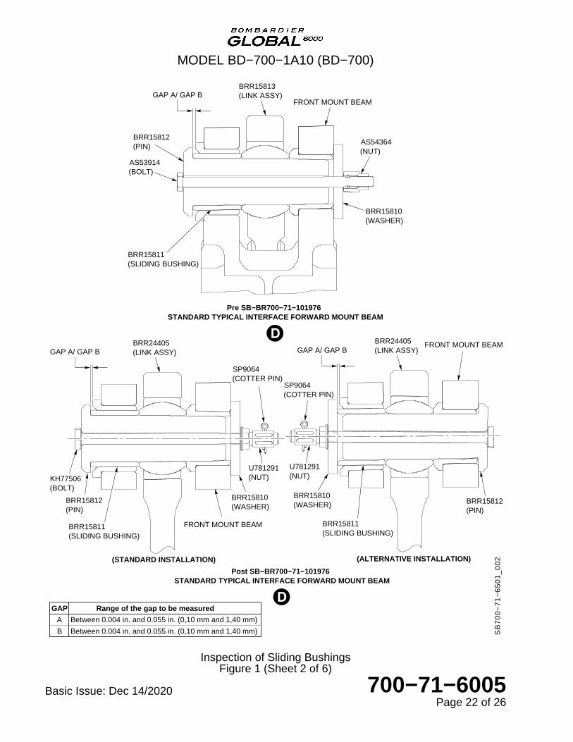
(1) Do the gap check at upper side of front mount beam as follows, refer toFigure 1, Detail C and D:
(a) Using a feeler gauge, measure Gap A between front mount beam pin, PartNo. BRR15812 and the shouldered bushing installed on the front mountbeam (standard installation), or gap between the shouldered bushinginstalled on the front mount beam and the washer Part No. BRR15810(alternative installation), must be between 0.004 and 0.055 in (0.10 and1.40 mm).
Record the results in Appendix (Table 1) and send it to TS by E−mail [email protected].
NOTE: If the gap is not within acceptable limits, fill out an SRPSA andsend it by E−mail at:
MODEL BD−700−1A10 (BD−700)
Basic Issue: Dec 14/2020 700−71−6005Page 8 of 26
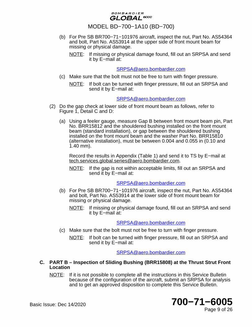
(b) For Pre SB BR700−71−101976 aircraft, inspect the nut, Part No. AS54364and bolt, Part No. AS53914 at the upper side of front mount beam formissing or physical damage.
NOTE: If missing or physical damage found, fill out an SRPSA and sendit by E−mail at:
(c) Make sure that the bolt must not be free to turn with finger pressure.
NOTE: If bolt can be turned with finger pressure, fill out an SRPSA andsend it by E−mail at:
(2) Do the gap check at lower side of front mount beam as follows, refer toFigure 1, Detail C and D:
(a) Using a feeler gauge, measure Gap B between front mount beam pin, PartNo. BRR15812 and the shouldered bushing installed on the front mountbeam (standard installation), or gap between the shouldered bushinginstalled on the front mount beam and the washer Part No. BRR15810(alternative installation), must be between 0.004 and 0.055 in (0.10 and1.40 mm).
Record the results in Appendix (Table 1) and send it to TS by E−mail [email protected].
NOTE: If the gap is not within acceptable limits, fill out an SRPSA andsend it by E−mail at:
(b) For Pre SB BR700−71−101976 aircraft, inspect the nut, Part No. AS54364and bolt, Part No. AS53914 at the lower side of front mount beam formissing or physical damage.
NOTE: If missing or physical damage found, fill out an SRPSA and sendit by E−mail at:
(c) Make sure that the bolt must not be free to turn with finger pressure.
NOTE: If bolt can be turned with finger pressure, fill out an SRPSA andsend it by E−mail at:
C. PART B – Inspection of Sliding Bushing (BRR15808) at the Thrust Strut FrontLocation
NOTE: If it is not possible to complete all the instructions in this Service Bulletinbecause of the configuration of the aircraft, submit an SRPSA for analysisand to get an approved disposition to complete this Service Bulletin.
MODEL BD−700−1A10 (BD−700)
Basic Issue: Dec 14/2020 700−71−6005Page 9 of 26

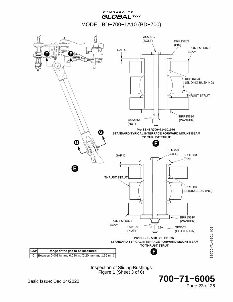
(1) Do the gap check at the thrust strut front location as follows, refer to Figure 1,Detail E and F:
(a) Using a feeler gauge, measure Gap C between the front mount beam pin,Part No. BRR15809 and the shouldered bushing installed on the frontmount beam, must be between 0.008 and 0.050 in (0.20 and 1.30 mm).
Record the results in Appendix (Table 2) and send it to TS by E−mail [email protected].
NOTE: If the gap is not within acceptable limits, fill out an SRPSA andsend it by E−mail at:
(b) For Pre SB BR700−71−101976 aircraft, inspect the nut, Part No. AS54364and bolt, Part No. AS53912 at the thrust strut front location for missing orphysical damage.
NOTE: If missing or physical damage found, fill out an SRPSA and sendit by E−mail at:
(c) Make sure that the bolt must not be free to turn with finger pressure.
NOTE: If bolt can be turned with finger pressure, fill out an SRPSA andsend it by E−mail at:
D. PART C — Inspection of Sliding Bushing (BRR15823) at the Thrust StrutAircraft Pylon Interface
NOTE: If it is not possible to complete all the instructions in this Service Bulletinbecause of the configuration of the aircraft, submit an SRPSA for analysisand to get an approved disposition to complete this Service Bulletin.
(1) Do the gap check at the thrust strut aircraft pylon interface as follows, refer toFigure 1, Detail E and G:
(a) Using a feeler gauge, measure the Gap D between the thrust strut pin,Part No. BRR15824 and the shouldered bushing installed on the thruststrut, must be between 0.008 and 0.055 in (0.20 and 1.40 mm).
Record the results in Appendix (Table 3) and send it to TS by E−mail [email protected].
NOTE: If the gap is not within acceptable limits, fill out an SRPSA andsend it by E−mail at:
MODEL BD−700−1A10 (BD−700)
Basic Issue: Dec 14/2020 700−71−6005Page 10 of 26

(b) For Pre SB BR700−71−101976 aircraft, inspect the nut, Part No. AS54364and bolt, Part No. AS53912 at the thrust strut aircraft pylon interface formissing or physical damage.
NOTE: If missing or physical damage found, fill out an SRPSA and sendit by E−mail at:
(c) Make sure that the bolt must not be free to turn with finger pressure.
NOTE: If bolt can be turned with finger pressure, fill out an SRPSA andsend it by E−mail at:
E. PART D — Inspection of Sliding Bushing (BRR15804) at the Front MountBeam Interface with the Aircraft Pylon Upper and Lower Installation
NOTE: If it is not possible to complete all the instructions in this Service Bulletinbecause of the configuration of the aircraft, submit an SRPSA for analysisand to get an approved disposition to complete this Service Bulletin.
(1) Do the gap check at the front mount beam Interface with the aircraft pylonupper installation as follows, refer to Figure 1, Detail C and H:
(a) Using a feeler gauge, measure Gap E between the front mount beam pin,Part No. BRR15805 and the shouldered bushing installed on the frontmount beam (standard installation) or gap between the washer Part No.BRR15807 and the shouldered bushing installed on the front mount beam(alternative installation), must be in between 0.008 and 0.048 in (0.20 and1.20 mm).
Record the results in Appendix (Table 4) and send it to TS by E−mail [email protected].
NOTE: If the gap is not within acceptable limits, fill out an SRPSA andsend it by E−mail at:
(2) Do the gap check at the front mount beam Interface with the aircraft pylonlower installation as follows, refer to Figure 1, Detail C and H:
(a) Using a feeler gauge, measure Gap F between the front mount beam pin,Part No. BRR15805 and the shouldered bushing installed on the frontmount beam (standard installation) or gap between the washer Part No.BRR15807 and the shouldered bushing installed on the front mount beam(alternative installation), must be in between 0.008 and 0.048 in (0.20 and1.20 mm).
MODEL BD−700−1A10 (BD−700)
Basic Issue: Dec 14/2020 700−71−6005Page 11 of 26

Record the results in Appendix (Table 4) and send it to TS by E−mail [email protected].
NOTE: If the gap is not within acceptable limits, fill out an SRPSA andsend it by E−mail at:
F. PART E — Inspection of Sliding Bushing (BRR15841) at the Rear MountBeam Interface with the Aircraft Pylon Upper and Lower Installation
NOTE: If it is not possible to complete all the instructions in this Service Bulletinbecause of the configuration of the aircraft, submit an SRPSA for analysisand to get an approved disposition to complete this Service Bulletin.
(1) Do the gap check at the rear mount beam Interface with the aircraft pylonupper installation as follows, refer to Figure 1, Detail K and L:
(a) Using a feeler gauge, measure Gap G between the rear mount beam pin,Part No. BRR15840 and the shouldered bushing installed on the rearmount beam (standard installation) or gap between the washer Part No.BRR15842 and the shouldered bushing installed on the rear mount beam(alternative installation), must be between 0.004 and 0.071 in (0.10 and1.80 mm).
Record the results in Appendix (Table 5) and send it to TS by E−mail [email protected].
NOTE: If the gap is not within acceptable limits, fill out an SRPSA andsend it by E−mail at:
(2) Do the gap check at the rear mount beam Interface with the aircraft pylon lowerinstallation as follows, refer to Figure 1, Detail K and L:
(a) Using a feeler gauge, measure Gap H between the rear mount beam pin,Part No. BRR15840 and the shouldered bushing installed on the rearmount beam (standard installation) or gap between the washer Part No.BRR15842 and the shouldered bushing installed on the rear mount beam(alternative installation), must be between 0.004 and 0.071 in (0.10 and1.80 mm).
Record the results in Appendix (Table 5) and send it to TS by E−mail [email protected].
NOTE: If the gap is not within acceptable limits, fill out an SRPSA andsend it by E−mail at:
MODEL BD−700−1A10 (BD−700)
Basic Issue: Dec 14/2020 700−71−6005Page 12 of 26

G. Close−out
NOTE: The steps in the Close−out section of this Service Bulletin, except for thereturn−to−service tests, are recommended steps. The steps give arecommendation to install components removed during the Aircraft Setup.This recommendation is to make sure that the aircraft is safe and ready toreturn to service. Alternative steps can be used at the operator’sdiscretion.
(1) Remove all tools, equipment and unwanted materials from the aircraft.
(2) Install the firebox lid 432CT/442CT. Refer to CMM 71−14−51 or 71−14−52.
(3) Install the upper cowl 432AT/442AT. Refer to AMM 71−10−00−410−801.
(4) Close the lower cowl 432AB/442AB. Refer to AMM 71−10−00−410−801.
(5) Install the firebox lower access panel 432BT/442BT. Refer to CMM 71−14−51or 71−14−52.
(6) Install the pylon panel for rear mount 412BB/422BB. Refer toAMM 54−52−01−400−801.
(7) Install the pylon panel for thrust strut and front mount 412AB/422AB. Refer toAMM 54−52−01−400−801.
(8) Do the activation of the thrust reverser (for maintenance). Refer toEMM BR700NG−A−78−30−00−01AAA−760A−A.
(9) Close the access door (311BB).
(10) In the flight compartment, on the EMS CDU, set the circuit breakers that followto IN. Refer to AMM 24−00−00−863−802.
For the left engine:
SYSTEM NAME CIRCUIT BREAKERNAME
BUS NAME
APU APU START BATT
ENGINE L FADEC CH A BATT
ENGINE L FADEC CH B BATT
ENGINE L ENG IGN 1 BATT
ENGINE L ENG IGN 2 BATT
ENGINE L ENG FUEL HPSOV BATT
ENGINE L ENG START A BATT
ENGINE L ENG START B BATT
THRUST REVERSER L T/R CTL VALVE BATT
MODEL BD−700−1A10 (BD−700)
Basic Issue: Dec 14/2020 700−71−6005Page 13 of 26

SYSTEM NAME CIRCUIT BREAKERNAME
BUS NAME
THRUST REVERSER L T/R UPPER LOCK BATT
THRUST REVERSER L T/R LOWER LOCK BATT
THRUST REVERSER L T/R TQA LOCK BATT
HYD HYD PUMP 1B AC 3
For the right engine:
SYSTEM NAME CIRCUIT BREAKERNAME
BUS NAME
APU APU START BATT
ENGINE R FADEC CH A BATT
ENGINE R FADEC CH B BATT
ENGINE R ENG IGN 1 BATT
ENGINE R ENG IGN 2 BATT
ENGINE R ENG FUEL HPSOV BATT
ENGINE R ENG START A BATT
ENGINE R ENG START B BATT
THRUST REVERSER R T/R CTL VALVE BATT
THRUST REVERSER R T/R UPPER LOCK BATT
THRUST REVERSER R T/R LOWER LOCK BATT
THRUST REVERSER R T/R TQA LOCK BATT
HYD HYD PUMP 2B AC 2
(11) Remove the tags and close the circuit breakers that follow:
For the left engine:
MODEL BD−700−1A10 (BD−700)
Basic Issue: Dec 14/2020 700−71−6005Page 14 of 26

LOCATION CB NO. NAME ZONE
DCPC A1 FIREX CH A 130
DCPC A2 FIREX CH B 130
DCPC A3 L ENG FUEL SOV 130
For the right engine:
LOCATION CB NO. NAME ZONE
DCPC A1 FIREX CH A 130
DCPC A2 FIREX CH B 130
DCPC A4 R ENG FUEL SOV 130
(12) Remove the tags and close the circuit breakers that follow:
For the left engine:
LOCATION CB NO. NAME ZONE
CCBP H7 PITOT 1 HT A 222
CCBP F5 PITOT 1 HT B 222
CCBP F6 PITOT 3 HT 222
CCBP F4 L AOA HEAT 222
CCBP F3 TAT HT 1 222
For the right engine:
LOCATION CB NO. NAME ZONE
CCBP B1 PITOT 2 HT 222
CCBP F10 STBY PITOT HT 222
CCBP H9 R AOA HEAT A 222
CCBP F8 R AOA HEAT B 222
CCBP F9 TAT HT 2 222
MODEL BD−700−1A10 (BD−700)
Basic Issue: Dec 14/2020 700−71−6005Page 15 of 26
H. Recording
When this Service Bulletin is completed, make an entry in the aircraft log, send theattached Incorporation Notice and the results Appendix Record Table toBombardier Business Aircraft Customer Services (BBACS).
For information, correction(s), comment(s) and/or feedback regarding ServiceBulletins released on the Customer Portal, please contact the Service BulletinGroup at the following email address:
3. MATERIAL INFORMATION
A. Kit
No kits required.
B. Parts
No parts required.
C. Material
No consumables are required.
D. Publications
No publications required.
MODEL BD−700−1A10 (BD−700)
Basic Issue: Dec 14/2020 700−71−6005Page 16 of 26

APPENDIX — RECORD TABLE
SPECIAL CHECK – FRONT AND REAR ENGINE MOUNT ASSEMBLIES –INSPECTION OF BUSHINGS ON THE ENGINE MOUNT SYSTEM
INSTRUCTIONS
Fill out the tables below. Refer to the instructions given in the Service Bulletin, and send thisAppendix to TS by E−mail at:
TABLE 1
Record the gap between the shouldered bushing installed on the front mount beamand the front mount beam pin (BRR15812), or the washer (BRR15810), as applicable.
*If the gap is not 0.004 and 0.055 in (0.10 and 1.40 mm), send an SRPSA [email protected].
Location in* or mm* Comments
L/H FrontMountBeam
Upper side(Gap A)
Lower side(Gap B)
R/H FrontMountBeam
Upper side(Gap A)
Lower side(Gap B)
MODEL BD−700−1A10 (BD−700)
Basic Issue: Dec 14/2020 700−71−6005Page 17 of 26

TABLE 2
Record the gap between the front mount beam pin (BRR15809) and the shoulderedbushing installed on the front mount beam.
*If the gap is not between 0.008 and 0.050 in (0.20 and 1.30 mm), send an SRPSA [email protected].
Location in* or mm* Comments
L/H Thrust Strut Front(Gap C)
R/H Thrust Strut Front(Gap C)
TABLE 3
Record the gap between the thrust strut pin (BRR15824) and the shouldered bushinginstalled on the thrust strut.
*If the gap is not between 0.008 and 0.055 in (0.20 and 1.40 mm), send an SRPSA [email protected].
Location in* or mm* Comments
L/H Thrust StrutAircraft Pylon
Interface (Gap D)
R/H Thrust StrutAircraft Pylon
Interface (Gap D)
TABLE 4
Record the gap between the shouldered bushing installed on the front mount beamand the front mount beam pin (BRR15805), or the washer (BRR15807), as applicable.
*If the gap is not between 0.008 and 0.048 in (0.20 and 1.20 mm), send an SRPSA [email protected].
MODEL BD−700−1A10 (BD−700)
Basic Issue: Dec 14/2020 700−71−6005Page 18 of 26

TABLE 4
Location in* or mm* Comments
L/H FrontMountBeam
interfacewith theAircraftPylon
UpperInstallation
(Gap E)
LowerInstallation
(Gap F)
R/H FrontMountBeam
interfacewith theAircraftPylon
UpperInstallation
(Gap E)
LowerInstallation
(Gap F)
TABLE 5
Record the gap between the shouldered bushing installed on the rear mount beamand the rear mount beam pin (BRR15840), or the washer (BRR15842), as applicable.
*If the gap is not between 0.004 and 0.071 in (0.10 and 1.80 mm), send an SRPSA [email protected].
Location in* or mm* Comments
MODEL BD−700−1A10 (BD−700)
Basic Issue: Dec 14/2020 700−71−6005Page 19 of 26

TABLE 5
L/H RearMountBeam
interfacewith theAircraftPylon
UpperInstallation
(Gap G)
LowerInstallation
(Gap H)
R/H RearMountBeam
interfacewith theAircraftPylon
UpperInstallation
(Gap G)
LowerInstallation
(Gap H)
MODEL BD−700−1A10 (BD−700)
Basic Issue: Dec 14/2020 700−71−6005Page 20 of 26
SB
70
0−
71
−6
50
1_
00
1
FRONT MOUNT/ THRUST STRUT ASSEMBLY
23
(LH SHOWN, RH SIMILAR)
MODEL BD−700−1A10 (BD−700)
Inspection of Sliding BushingsFigure 1 (Sheet 1 of 6)
Basic Issue: Dec 14/2020 700−71−6005Page 21 of 26
Pre SB−BR700−71−101976 STANDARD TYPICAL INTERFACE FORWARD MOUNT BEAM
Post SB−BR700−71−101976 STANDARD TYPICAL INTERFACE FORWARD MOUNT BEAM
(ALTERNATIVE INSTALLATION)
AS54364(NUT)
BRR15810(WASHER)
FRONT MOUNT BEAM
BRR15813(LINK ASSY)
BRR15812(PIN)
AS53914(BOLT)
BRR24405(LINK ASSY)
BRR24405(LINK ASSY)
KH77506(BOLT)
SP9064(COTTER PIN)
BRR15812(PIN)
U781291(NUT)
FRONT MOUNT BEAM
FRONT MOUNT BEAM
BRR15810(WASHER)
BRR15810(WASHER) BRR15812
(PIN)
GAP A/ GAP B GAP A/ GAP B
GAP A/ GAP B
SB
70
0−
71
−6
50
1_
00
2(STANDARD INSTALLATION)
GAP
A
B
Range of the gap to be measured
Between 0.004 in. and 0.055 in. (0,10 mm and 1,40 mm)
Between 0.004 in. and 0.055 in. (0,10 mm and 1,40 mm)
U781291(NUT)
SP9064(COTTER PIN)
BRR15811(SLIDING BUSHING)
BRR15811(SLIDING BUSHING)
BRR15811(SLIDING BUSHING)
MODEL BD−700−1A10 (BD−700)
Inspection of Sliding BushingsFigure 1 (Sheet 2 of 6)
Basic Issue: Dec 14/2020 700−71−6005Page 22 of 26
Pre SB−BR700−71−101976 STANDARD TYPICAL INTERFACE FORWARD MOUNT BEAM
TO THRUST STRUT
SB
70
0−
71
−6
50
1_
00
3
BRR15809(PIN)
FRONT MOUNTBEAM
BRR15810(WASHER)AS54364
(NUT)
THRUST STRUT
GAP C
Post SB−BR700−71−101976 STANDARD TYPICAL INTERFACE FORWARD MOUNT BEAM
TO THRUST STRUT
BRR15810(WASHER)
U781291(NUT)
SP90C4(COTTER PIN)
THRUST STRUT
KH77506(BOLT) BRR15809
(PIN)
FRONT MOUNTBEAM
GAP C
AS53912(BOLT)
GAP
C
Range of the gap to be measured
Between 0.008 in. and 0.050 in. (0,20 mm and 1,30 mm)
BRR15808(SLIDING BUSHING)
BRR15808(SLIDING BUSHING)
MODEL BD−700−1A10 (BD−700)
Inspection of Sliding BushingsFigure 1 (Sheet 3 of 6)
Basic Issue: Dec 14/2020 700−71−6005Page 23 of 26

Pre SB−BR700−71−101976 STANDARD TYPICAL INTERFACE THRUST STRUT TO AIRCRAFT PYLON
SB
70
0−
71
−6
50
1_
00
4
AIRCRAFT PYLON
THRUST STRUT
AS54364(NUT)
BRR15824(PIN)
BRR15810(WASHER)
AS53912(BOLT)
GAP D
Post SB−BR700−71−101976 STANDARD TYPICAL INTERFACE THRUST STRUT TO AIRCRAFT PYLON
GAP D
U781291(NUT)
BRR15824(PIN)
THRUST STRUT
BRR15810(WASHER)
KH77506(BOLT)
AIRCRAFT PYLON
SP90C4(COTTER PIN)
GAP
D
Range of the gap to be measured
Between 0.008 in. and 0.055 in. (0,20 mm and 1,40 mm)
BRR15823(SLIDING BUSHING)
BRR15823(SLIDING BUSHING)
MODEL BD−700−1A10 (BD−700)
Inspection of Sliding BushingsFigure 1 (Sheet 4 of 6)
Basic Issue: Dec 14/2020 700−71−6005Page 24 of 26

REAR MOUNT ASSEMBLY
SB
70
0−
71
−6
50
1_
00
5
TYPICAL INTERFACE FRONT MOUNT BEAM
SP90G6(COTTER PIN)
U755248(NUT)
SP90G6(COTTER PIN)
BRR15807(WASHER)
BRR15805(PIN)
BRR15806(BOLT)
BRR15805(PIN)
BRR15806(BOLT)
BRR15804(SLIDING BUSHING)
U755248(NUT)
FRONT MOUNT BEAM
GAP E/ GAP F
FRONT MOUNT BEAM
GAP E/ GAP F
GAP
E
F
Range of the gap to be measured
Between 0.008 in. and 0.048 in. (0,20 mm and 1,20 mm)
Between 0.008 in. and 0.048 in. (0,20 mm and 1,20 mm)
(ALTERNATIVE INSTALLATION)(STANDARD INSTALLATION)
BRR15804(SLIDING BUSHING)
MODEL BD−700−1A10 (BD−700)
Inspection of Sliding BushingsFigure 1 (Sheet 5 of 6)
Basic Issue: Dec 14/2020 700−71−6005Page 25 of 26

TYPICAL INTERFACE REAR MOUNT BEAM − AIRCRAFT PYLON
GAP GGAP G
BRR15840(PIN)
BRR16268(BOLT)
BRR15842(WASHER)
U755248(NUT)
SP90G6(COTTER PIN)
GAP H
U755248(NUT)
SP90G6(COTTER PIN)
BRR15842(WASHER)
BRR16268(BOLT)
BRR15840(PIN)
SP90G6(COTTER PIN)
U755248(NUT)
BRR15842(WASHER)
BRR16268(BOLT)
BRR15840(PIN)
REAR MOUNTBEAM
REAR MOUNTBEAM
BRR15840(PIN)
BRR16268(BOLT)
GAP HSP90G6(COTTER PIN)
U755248(NUT)
BRR15842(WASHER)
GAP
G
H
Range of the gap to be measured
Between 0.004 in. and 0.071 in. (0,10 mm and 1,80 mm)
Between 0.004 in. and 0.071 in. (0,10 mm and 1,80 mm) SB
70
0−
71
−6
50
1_
00
6
(ALTERNATIVE INSTALLATION)(STANDARD INSTALLATION)
BRR15841(SLIDING BUSHING)
BRR15841(SLIDING BUSHING)
BRR15841(SLIDING BUSHING)
BRR15841(SLIDING BUSHING)
MODEL BD−700−1A10 (BD−700)
Inspection of Sliding BushingsFigure 1 (Sheet 6 of 6)
Basic Issue: Dec 14/2020 700−71−6005Page 26 of 26

700−71−6005 Basic Dec 14/2020
SPECIAL CHECK – FRONT AND REAR ENGINE MOUNT ASSEMBLIES –INSPECTION OF BUSHINGS ON THE ENGINE MOUNT SYSTEM
NOTE: Please use Salesforce only for troubleshooting issues or when Engineeringdeviation is necessary to accomplish the Service Bulletin modification.
SERVICE BULLETIN EVALUATION FORM(Your ideas will help us provide better bulletins)
SERVICE BULLETIN: ISSUE: DATED:
TITLE:
For any information, correction(s), comment(s) and/or feedback regarding ServiceBulletins released on the Customer Portal, please contact the Service Bulletin Groupat the following email address:

SERVICE BULLETIN INCORPORATION SHEET − "700−71−6005"
Upon completion of the Service Bulletin, please fill−in, fax to(514) 855−8798 or e−mail to Fracas at [email protected]
If you’re reporting Service Bulletin (SB) Incorporations to CAMP, sendingthis Incorporation Sheet to Bombardier is not mandatory. If your aircraft ison another tracking system, please contact Bombardier to make arrangementsfor automated data submission.
700−71−6005 Basic
COMPLIED WITH
YES NO N/A
Actual hours to accomplish Service Bulletin:
* NOTES:
Aircraft Serial No. Aircraft Reg. No.
Airframe Hours: Airframe Landings
S.B. Incorporation Date Service Order No.
Facility incorporating S.B.
Name Signature Date
BO
MB
AR
DIE
RS
UB
MIS
SIO
N
Service BulletinNumber
Rev. * PartsCompleted
Remarks/Reason(Mandatory if N/A)
1. Where the Service Bulletin is divided into a number of parts (e.g., PARTS A,B, C, D, etc.) which can be carried out separately, indicate only those partscompleted at this time.
2. For repetitive checks (usually PART A) only the initial check should bereported unless otherwise stated in the Service Bulletin.
3. When more than one part is carried out at the same time, each part shouldbe reported.
4. Fill in ’Remark/Reason’ to explain compliance method when N/A is selected.(E.g. Partnot installed, N/A by effectivity, N/A by Part Serial Number, etc.
5. PCW means ’Previously Complied With’.
(dd/mm/yy)
Signature not required if sent by E−Mail (dd/mm/yy)