service bulletin no · noncompliance report, service bulletin 9230 and field modification...
TRANSCRIPT

Printed in Canada
Service Bulletin No.335MODEL TYPE SECTION/GROUP DATE
SUBJECT
CONDITIONS
Nov. 6, 2009D Series Coaches w/
Luminator Destination Signs Field Change Program 3--Body
LUMINATOR HORIZON LED SIDE DESTINATION AND ROUTE SIGNS
Ref. NHTSA Luminator Recall No.: 09E--054Ref. NHTSA MCI Recall No.: 09V--432Ref. Transport Canada MCI Recall No.: 09--318
Defect:Luminator Holding, LP ( Luminator ) has reported toMotor Coach Industries (MCI ) that a defect relating tomotor vehiclesafety exists in certain Luminator Horizon LED display side destination and route signs. Luminator reports that theaffected signs are those signs equipped with the 506476 connector board that is used to “daisy chain” the sidedestination sign to other signs in the sign system. When there is no rear sign one connector is left uncovered by themissing cable. This creates an open connector condition that allows debris to collect inside the connector andprovidesa path for moisture to ingress along the pins of the connector down to the PWA board itself, causing corrosion on thesolder connection between the open connector and PWA board. The corrosion allows for a conductive path betweenbattery voltage and ground. This corrosion will allow a potential short and the sign will fail. In rare instances, thiscorrosion will cause the sign to smoke and possibly flame. Please see the attached Luminator Defect andNoncompliance Report, Service Bulletin 9230 and Field Modification Instructions.Due to the manner in which MCI installs the signs in MCI coaches, the recall affects only those coaches that have aLuminator Horizon LED display side destination or route sign, and not a rear sign.
Cause:Luminator reports that the corrosion is caused by an accumulation ofmoisture under the connector, but that none of theconnectors which have a cable attached to them show any sign of corrosion. The base of the connector is too close tothe board to effectively coat the solder connections with conformal coating ( a corrosion preventative ). This corrosioncreates the conductive path between battery voltage and ground pins. Certain cleaning practices ( i.e., spraying waterand cleaning agents ) used by operators introduce more moisture into the connector and increase the likelihood of thecorrosion.
Corrective Action:MCI recommends that the side destination and route signs on affected coaches be inspected and have new partsinstalled as per the attached Luminator Service Bulletin 9230 and Field Modification Instructions. Due to the manner inwhich MCI installs the signs in MCI coaches, the recall affects only those coaches that have a Luminator Horizon LEDdisplay side destination or route sign, and not a rear sign.Accordingly, MCI advises that owners of D model coaches between the range of, and including, unit numbers54819---59097 and containing a Luminator Horizon LED display side destination or route sign without a rear signimplement the specified steps in the attached Luminator Service Bulletin 9230 and Field Modification Instructions.

Printed in Canada
PAGEDATE 2NOV. 06, 2009Service Bulletin No. 335
Service Information:The Luminator signs have a product label that includes a date code ( refer to Figure 1 ). The first two digits of the datecode indicate the year the sign was manufactured. The second two digits indicate the week of the manufacture.
Figure 1. Reference photo of date code product label located on top of the side sign frame.
For signs manufactured prior to 2008 ( i.e., date codes prior to 0801 ), Luminator will replace the connector board with anewly designed board. Luminator advises that the new board eliminates the possibility of arcing by putting the groundandbattery voltage on separate layers of the board. The traces have alsobeenmoved toallow themaximumspacing. Inaddition, conformal coating has been applied below the connector and a cap is installed on all open connectors toprevent the incursion of moisture and debris which would allow corrosion to develop.For signs manufactured in 2008 or later, Luminator will provide a vinyl cap for any open connectors and a moisturedisplacing corrosion inhibitor spray and procedure to be used to clean the connectors and thereby eliminate theconditions that permitted moisture to ingress and produce the corrosion.Required parts and labor allowance for this recall will be providedbyLuminator. MCI customers are instructed to contactLuminator at 1-972-516-3074 for all inquiries.

Printed in Canada
PAGEDATE 3NOV. 06, 2009Service Bulletin No. 335
Service Procedure:
General notesRead this entire procedure before beginning work.Use Safe Shop Practices At All Times.
1. Turn the main battery disconnect switch to the OFF position.2. Open the engine door. Position the ENGINE RUNand ENGINE START switches on the engine remote boxto the OFF position.
REFER TO MANUALRefer to Section 3B3 / Destination Sign System, in the MCI D Series Maintenance Manual, in conjunctionwith this procedure.
3. Gain access to the sign by loosening the bottom capscrew and removing the top capscrew from the panelon the sign assembly ( refer to Figure 2 ). Using two hands, support the panel as it rotates downward.Retain top capscrew.
removeand retainmountingcapscrew
loosenmountingcapscrew
Figure 2. Reference photo of side sign assembly.

Printed in Canada
PAGEDATE 4NOV. 06, 2009Service Bulletin No. 335
4. Perform the outlined steps in the attached Luminator Service Bulletin 9230 and Field ModificationInstructions.
5. Upon completion of attached Luminator Service Bulletin 9230 and Field Modification Instructions, alignand re-connect the power / data cable. Spin the collar counter-clockwise to secure plug.
6. Close panel and re-install top capscrew removed in Step 3. Tighten top and bottom capscrews tosecure.
7. Position the ENGINE RUN and ENGINE START switches on the engine remote box to the ON position.Close the engine door.
8. Turn the main battery disconnect switch to the ON position.9. Verify to ensure proper function of sign(s).
Procedure complete.
Field Change Program Conditions:Luminator will provide the materials and labor to complete this recall at no charge.MotorCoach apologizes for any inconvenience resulting from this campaign, but urges you to implement this change assoon as possible.
Sincerely,
Motor Coach IndustriesU.S. and Canadian Service Departments.


FORM 902431 REV B On Board Since 1934
Luminator Bulletin
Section 1
Service Bulletin Number: 9230 Part number and description: 506746 PWA, SIDE CONNECTOR HORIZON
Date: 08/11/2009
Quality Bulletin Type: Service
Responsibility: Luminator
Drawing/Specification: 506746 (dwg.)
Revision: F
Other information: Luminator Contact Information: Materials Technical A. Brett T. Zagaruyka 972-516-3074 972-516-3021 Problem description: This notice is to alert operators that corrosion on connector pins may result in premature product failure. Corrosion may potentially form in a high humidity environment or where moisture is present. This corrosion raises the potential of pin shorting that may result in failure. If not addressed the failure could result in a potential electrical short or lead to smoking or in rare instances fire. This notice only affects buses equipped with the following configurations: Front and side sign but no rear sign Curb and roadside side and/or route signs Corrective Action: The corrosion on the pins must be removed and all exposed connectors must to be covered to eliminate the possibility of additional corrosion. Buses 2007 and older are more likely to have corrosion to such an extent that the failure may occur. These buses will have the connector boards replaced.
Section 2 Action(s) to be taken: Do not leave buses running unattended for more than 30 minutes. Transit Authority:
1. Notify Luminator of the number, age and location of all buses with configurations outlined above. (See attached format)
2. Once modifications are completed, all paperwork will be filled out and returned to Luminator for tractability. Luminator:
1. Once this information is received by Luminator Field Modification Instructions (FMI) and materials will be provided to all operators to make the necessary modifications to their buses.
2. If assistance is needed Luminator will provide field service personnel to complete modifications.
Effectivity date: 8/17/2009
Section 3 Comments:
Issued by: Eric Marquet Title: Director of Quality Assurance Date: 09/10/2009

THE INFORMATION CONTAINED IN THIS DOCUMENT IS PROPRIETARY TO LUMINATOR, A MARK IV INDUSTRIES COMPANY, AND SHALL NOT BE USED OR REPRODUCED FOR ANY PURPOSE WITHOUT PRIOR WRITTEN CONSENT.
Project Engineer Masias, Marty
DATE 09/04/2009
Luminator A MARK IV INDUSTRIES COMPANY PLANO, TEXAS
Checker R. Harness
DATE 09/17/2009
Project Manager Konecki, Nancy
DATE 09/04/2009
TITLE FIELD MODIFICATION INSTRUCTIONS FOR
HORIZON SIDE SIGN OPEN CONNECTOR COVER
SIZE
A CODE IDENT. NO.
17744 DRAWING NO.
904666
SCALE NONE REV. B SHEET 1 OF 10
REVISIONS
NEXT ASSY USED ON REV ECO DESCRIPTION DATE CHECK
A 74834 INITIAL RELEASE 09/17/09 RH
B
FIELD MODIFICATION INSTRUCTIONS
FOR
HORIZON SIDE SIGN OPEN CONNECTOR INSTALLATION AND CONNECTOR PWA REPLACEMENT

SIZE CODE IDENT. NO. DWG. NO.
A 17744 904666 Luminator
A Mark IV Industries Company Plano, Texas
SCALE NONE REV. B SHEET 2
WARNINGS
BE SURE ELECTRIC POWER IS OFF BEFORE WORKING ON WIRING. FAILURE TO DO SO MAY RESULT IN DAMAGE TO SIGN EQUIPMENT AND RENDER SIGN INOPERATIVE.
USE CAUTION WHEN SPRAYING CORROSION X TO AVOID SPRAY DRIPPING ON SURROUNDING MATERIALS. SAFETY GLASSES SHOULD BE WORN WHEN USING AEROSOL CLEANING AGENTS TO AVOID EYE INJURY. IF SPRAY CONTACTS SKIN, WASH AS DIRECTED ON CAN.

SIZE CODE IDENT. NO. DWG. NO.
A 17744 904666 Luminator
A Mark IV Industries Company Plano, Texas
SCALE NONE REV. B SHEET 3
1.0 OBJECTIVE
This Field Modification procedure contains instructions for reworking Horizon LED display side signs and side route signs with an open connector on buses without a rear sign.
On 2007 and older buses the connector PWA part number 506746-001 will be replaced with connector board part number 508331-001 and with vinyl cap part number 801403-001.
On 2008 and newer buses, a vinyl cap, part number 801403-001 will be added to the open connector.
NOTE: Some Transit Properties may have a street side and curb side sign. Every side sign and side route signs will require a vinyl cap if there is an open connector.
2.0 REASON FOR CHANGES
On signs with an open connector, debris, moisture, corrosion, etc. can cause a short to develop between power connections possibly resulting in sign failure and in rare instances smoke and/or fire.
3.0 REFERENCE DOCUMENTS
Luminator Part Number
Description ICD Drawing
510545-ALL Horizon LED side sign ICD510545
510544-ALL Horizon LED Side Sign, 4" ICD510544
510565 ALL Horizon LED Side Route Sign ICD510565

SIZE CODE IDENT. NO. DWG. NO.
A 17744 904666 Luminator
A Mark IV Industries Company Plano, Texas
SCALE NONE REV. B SHEET 4
4.0 COMPONENTS REQUIRED
Description 2007 and Older Required Part
Numbers
2008 and newer Part Numbers
Cap, Vinyl, .75 INCH ID 801403-001 801403-001
Corrosion X Cleaner/Penetration spray 801409-001 801409-001
Connector PWA 508331-001
Hardware retained from signs at removal NA NA
Label, FMI NA NA
5.0 TOOLS REQUIRED
• Safety Glasses
• Screwdriver, No. 2 and No. 3 Phillips
• 3/8” Wrench and/or Ratchet with 3/8” socket
• 7/16” Nut driver and/or Ratchet with 7/16” socket
6.0 PROCEDURES AND RECOMMENDATIONS PART 1 – 2007 AND OLDER BUSES SEE SECTION 6.1
PART 2 – 2008 AND NEWER BUSES SEE SECTION 6.2
6.1 CONNECTOR BOARD INSTALLATION IN BUSES 2007 AND OLDER
1 Verify sign operation before proceeding.
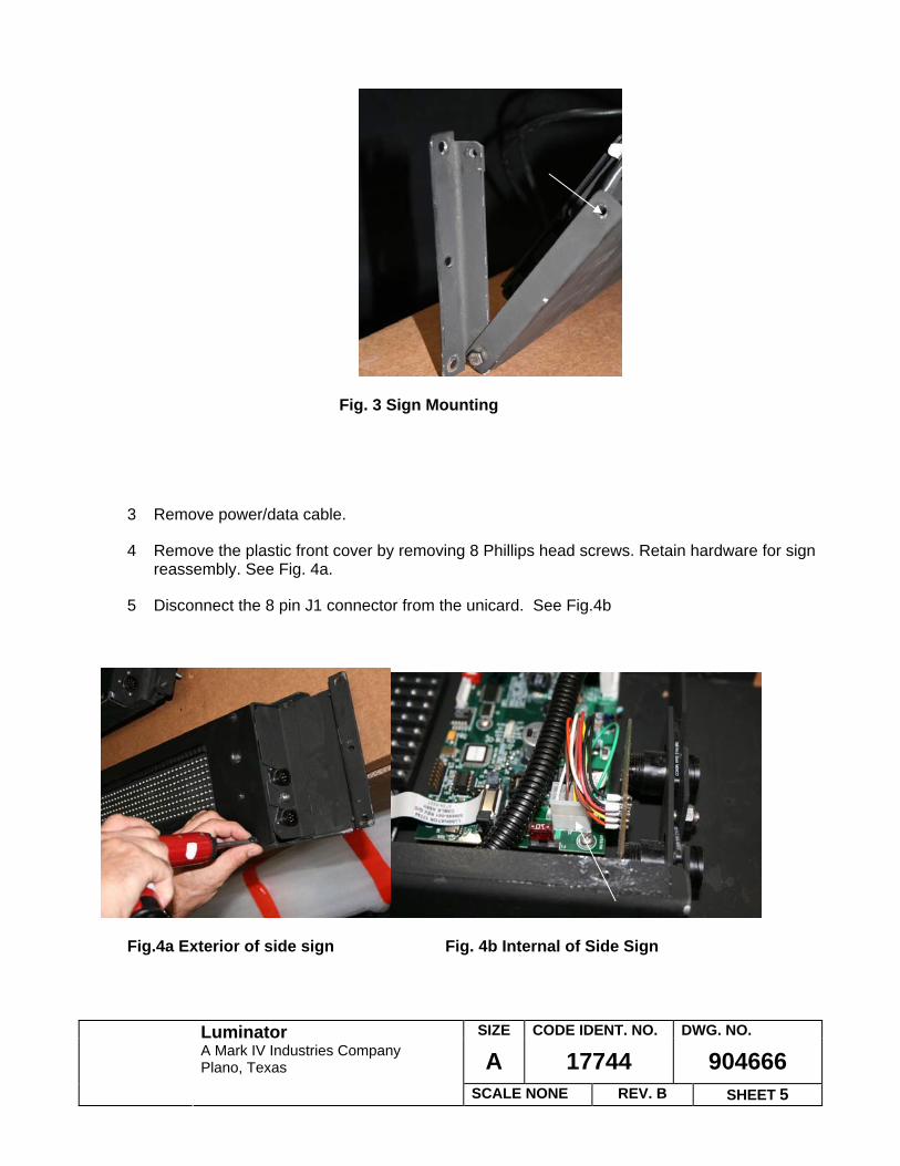
2 Gain access to power/data connector located on end panel of sign by removing top 2 mounting bolts and rotating sign downwards. Retain hardware for sign reinstallation. Vehicle type and manufacturer will determine access to cable connector. See Fig. 3
Note: Sign may need to be removed completely if there is not enough clearance between the sign and the window frame.
SIZE CODE IDENT. NO. DWG. NO.
A 17744 904666 Luminator
A Mark IV Industries Company Plano, Texas
SCALE NONE REV. B SHEET 5
Fig. 3 Sign Mounting
3 Remove power/data cable.
4 Remove the plastic front cover by removing 8 Phillips head screws. Retain hardware for sign reassembly. See Fig. 4a.
5 Disconnect the 8 pin J1 connector from the unicard. See Fig.4b
Fig.4a Exterior of side sign Fig. 4b Internal of Side Sign

SIZE CODE IDENT. NO. DWG. NO.
A 17744 904666 Luminator
A Mark IV Industries Company Plano, Texas
SCALE NONE REV. B SHEET 6
6 Depending on sign type a Phillips screw driver or a 7/16 socket will be needed to remove the connector board. Retain hardware for sign reassembly. See Fig. 5 and 6
Fig. 5 (screw mounting) Fig. 6 (Bracket mounting)
7 For screw mounting (Figure 5) Remove 2 mounting nuts and rotate bracket outwards to remove. Remove 7 screws to release connector from bracket. Reverse procedure to install new connector board
8 For Bracket Mounting (Figure 6) Remove mounting nut and slide bracket back and pull up to remove. Pull connector board up and out. Reverse procedure to install new connector board.
9 Reassemble sign by performing Steps 8 – 2 in reverse order.
10 Confirm that light pipe is still properly installed per Figure 7.
Figure 7, Light Pipe Installation

SIZE CODE IDENT. NO. DWG. NO.
A 17744 904666 Luminator
A Mark IV Industries Company Plano, Texas
SCALE NONE REV. B SHEET 7
11 Reattach power/data cable.
12 Install vinyl cap on open (unused) connector.
13 Reinstall sign assembly on bus.
14 Check sign for proper operation. Cycling power to the sign system may be required for the side sign to be recognized.
15 Record bus number, bus type, technician performing work, type of work completed and date work was completed on the FMI log sheet. See section 7 for Disposition of Materials
16 Install FMI label near part number label on the top of the sign.
6.2 VINYL CAP INSTALLATION PROCEDURE FOR 2008 AND NEWER BUSES
1 Verify sign operation before proceeding.
2 Gain access to power/data connector located on end panel of sign by removing top 2 mounting bolts and rotating sign downwards. Retain hardware for reassembly. Vehicle type and manufacturer will determine access to cable connector. See Fig. 1
Note: Sign may need to be removed completely if there is not enough clearance between the sign and the window frame.
Fig. 1 Sign Mounting

SIZE CODE IDENT. NO. DWG. NO.
A 17744 904666 Luminator
A Mark IV Industries Company Plano, Texas
SCALE NONE REV. B SHEET 8
3 Note which connector has the power/data cable connected. Disconnect cable from sign. This connector will not require Corrosion X.
4 Spray Corrosion X into the uncovered connector for about 2 second so that it penetrates into the connector down to the PWA inside the sign. See Fig. 2
Fig. 2 Spray Corrosion X in unused connector
5 Install vinyl cap on same connector.
6 Reattach power/data cable. Corrosion X is a dielectric. Power may be applied to the sign immediately after application.
7 Reinstall sign assembly on bus.
8 Check sign for proper operation. Cycling power to the sign system may be required for the side sign to be recognized.
9 Record bus number, technician performing work, date work was completed and type of work performed (I.e. spray and cap or PWA replacement) on the FMI log sheet. See section 7 for Disposition of Materials
10 Install FMI label near part number label on the top of the sign.

SIZE CODE IDENT. NO. DWG. NO.
A 17744 904666 Luminator
A Mark IV Industries Company Plano, Texas
SCALE NONE REV. B SHEET 9
7.0 SCHEDULE OF WORK/RESPONSIBILITY FOR MODIFICATION
7.1 Material
Luminator will provide all materials and procedures to complete modifications at no charge.
7.2 Labor
At the customer's option, they can perform the procedures and be responsible for the work.
7.3 Disposition of Materials
1. Collect all removed connector PWA boards.
2. Using prepaid label provided, return all defective connector board PWAs and the FMI Log Sheet, signed by local Maintenance Supervisor to: Luminator 900 Klein Road Plano, TX 75074 Attn: A. Brett
SIZE CODE IDENT. NO. DWG. NO.
A 17744 904666 Luminator
A Mark IV Industries Company Plano, Texas
SCALE NONE REV. B SHEET 10
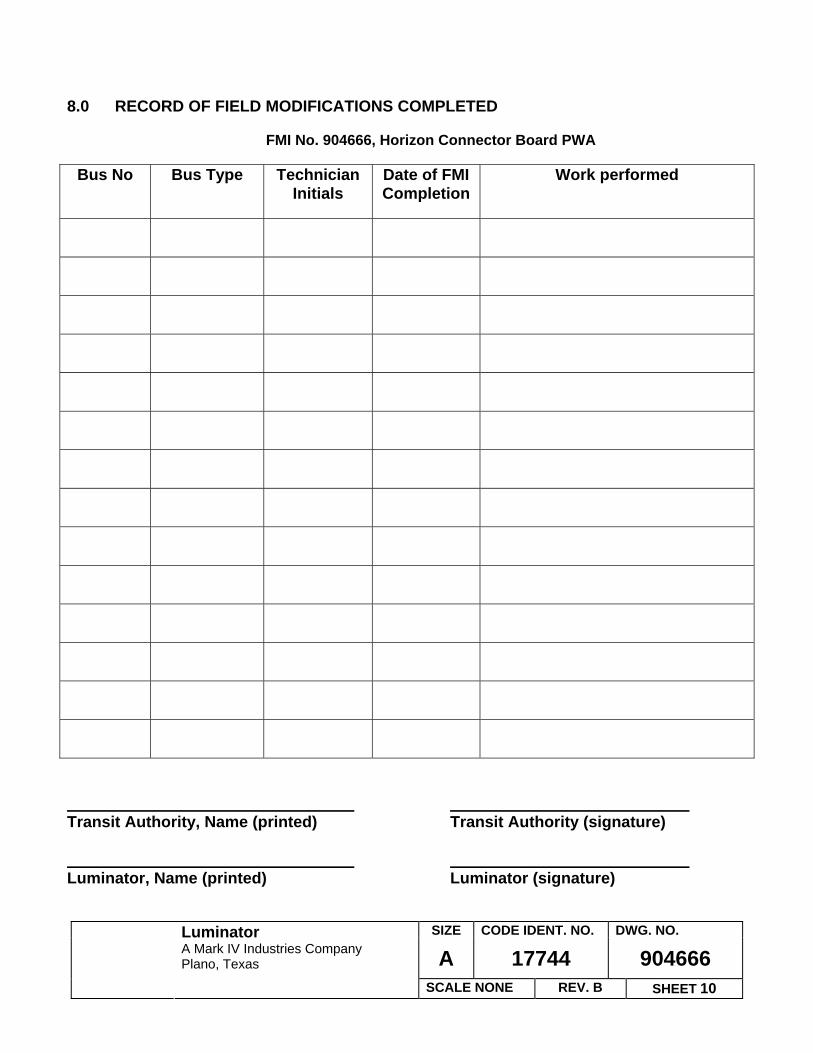
8.0 RECORD OF FIELD MODIFICATIONS COMPLETED
FMI No. 904666, Horizon Connector Board PWA
Bus No Bus Type Technician Initials
Date of FMI Completion
Work performed
Transit Authority, Name (printed) Transit Authority (signature) Luminator, Name (printed) Luminator (signature)