service bulletin - diagramas dediagramas.diagramasde.com/otros/imagerunner ir2200...-1/3-service...
TRANSCRIPT

- 1 / 3 -
Service BulletinIssued by Canon Europa N.V.
Model: iR2200/2800/3300 Series No.: iR3300-005 Rev. 1
(FF-T01-L5-000019-02)
DATE: 30.08.02
Location: Cassette Size Detection Assembly
Subject: Wrong Detection of Cassette Size
Reason: The cassette size detection mechanism at times fails to detect the correct size of the cassette; this
bulletin offers measures to ensure correct detection.
Detail:<Symptom>
When the cassette is fitted, the control panel indicates the message [LOAD PAPER].
<Cause>
When the cassette is slid into the machine, the cable from the cassette size detection assembly can
push and tilt the assembly; and the poor engagement between the assembly and the cam hinge in turn
can cause wrong detection of cassette size.
COPIER
Cassette As Fitted Normally Cassette Fitted to Cause Wrong Detection
Cable
Cassette size detection assembly
Cam hinge
Tilt
The cable forces the detection assembly askew.

iR3300-005 Rev. 1
- 2 / 3 -
<Factory Measures>
1. Cam Hinge (instead of FB5-4740-000, use FB5-4740-020)
The protrusion is lengthened so that the cam hinge will more easily slide into the cassette size
detection assembly. At the same time, the presence of a taper ensures that the cam hinge will
securely engage with the cassette size detection assembly.
2. Right Panel (front) (instead of FB5-4741-000, use FB5-4741-030)
Ribs are added to the right panel (front), thus preventing a tilt of the cassette size detection
assembly.
Taper
Add ribs to the back of the right panel (front).
Add a taper to the cam hinge.
Lengthen the protrusion of the cam hinge.
Add ribs to the right panel (front).Protrusion
iR3300-005 Rev. 1
- 3 / 3 -
Servicing Work:If the cassette size detection assembly fails to detect the correct size of the cassette, replace the cam
hinge and the right panel (front) at the same time.
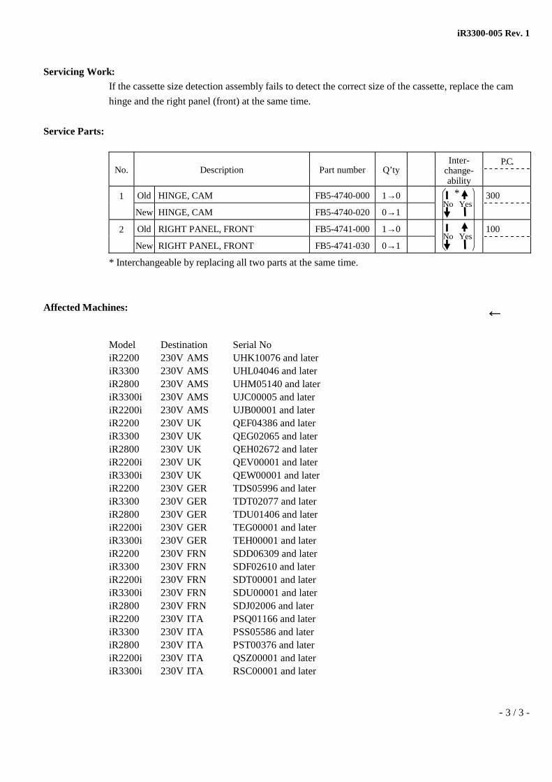
Service Parts:
P.C.No. Description Part number Q’ty
Inter-change-ability
1 Old HINGE, CAM FB5-4740-000 1→0 300
New HINGE, CAM FB5-4740-020 0→1
2 Old RIGHT PANEL, FRONT FB5-4741-000 1→0 100
New RIGHT PANEL, FRONT FB5-4741-030 0→1
* Interchangeable by replacing all two parts at the same time.
Affected Machines: ←
Model Destination Serial NoiR2200 230V AMS UHK10076 and lateriR3300 230V AMS UHL04046 and lateriR2800 230V AMS UHM05140 and lateriR3300i 230V AMS UJC00005 and lateriR2200i 230V AMS UJB00001 and lateriR2200 230V UK QEF04386 and lateriR3300 230V UK QEG02065 and lateriR2800 230V UK QEH02672 and lateriR2200i 230V UK QEV00001 and lateriR3300i 230V UK QEW00001 and lateriR2200 230V GER TDS05996 and lateriR3300 230V GER TDT02077 and lateriR2800 230V GER TDU01406 and lateriR2200i 230V GER TEG00001 and lateriR3300i 230V GER TEH00001 and lateriR2200 230V FRN SDD06309 and lateriR3300 230V FRN SDF02610 and lateriR2200i 230V FRN SDT00001 and lateriR3300i 230V FRN SDU00001 and lateriR2800 230V FRN SDJ02006 and lateriR2200 230V ITA PSQ01166 and lateriR3300 230V ITA PSS05586 and lateriR2800 230V ITA PST00376 and lateriR2200i 230V ITA QSZ00001 and lateriR3300i 230V ITA RSC00001 and later
No Yes
No Yes*

- 1 / 8 -
Service Bulletin
Issued by Canon Europa N.V.
Model: iR2200/2800/3300 Series No.: iR3300-006
(FF-T01-L5-000016-01)
DATE: 26.04.02
Location: Pickup Assembly FG6-5644
Subject: Measure Against Cassette Lifter Failure to Rise
Reason: Loose engagement of lifter arm claws and ratchet gear
Detail: <Symptom>
Sometimes the lifter plate fails to rise and the paper empty alarm is issued even though paper is set in
the cassette.
<Cause>
Because of the multiple parts tolerances involved, sometimes the space between the boss on the pickup
frame cover (FB5-4728-000) and the lifter arm claws (FB6-2789-000) opens too wide, allowing the
claws to travel over greater distances in the thrusting direction and eventually letting the arm claws fall
out of engagement with the ratchet gear (FB6-2778-000).
COPIER
Lifter arm claw
Stainless steel shaft(FB4-2816-000)
Frame cover(FB5-4728-000)
Excess gap allows greater freedom ofthe arm claws in the thrusting direction.
Frame cover boss
iR3300-006
- 2 / 8 -
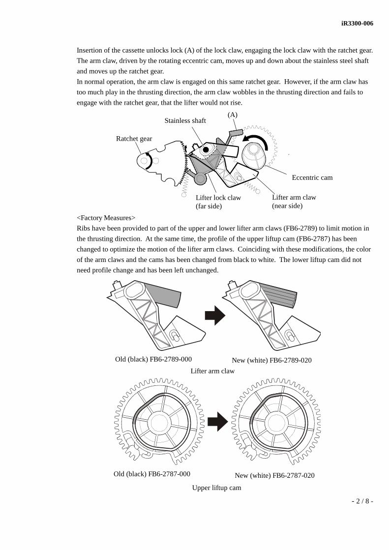
Insertion of the cassette unlocks lock (A) of the lock claw, engaging the lock claw with the ratchet gear.
The arm claw, driven by the rotating eccentric cam, moves up and down about the stainless steel shaft
and moves up the ratchet gear.
In normal operation, the arm claw is engaged on this same ratchet gear. However, if the arm claw has
too much play in the thrusting direction, the arm claw wobbles in the thrusting direction and fails to
engage with the ratchet gear, that the lifter would not rise.
<Factory Measures>
Ribs have been provided to part of the upper and lower lifter arm claws (FB6-2789) to limit motion in
the thrusting direction. At the same time, the profile of the upper liftup cam (FB6-2787) has been
changed to optimize the motion of the lifter arm claws. Coinciding with these modifications, the color
of the arm claws and the cams has been changed from black to white. The lower liftup cam did not
need profile change and has been left unchanged.
Ratchet gear
Stainless shaft
Lifter lock claw(far side)
Lifter arm claw(near side)
Eccentric cam
(A)
New (white) FB6-2789-020Old (black) FB6-2789-000
Old (black) FB6-2787-000
Lifter arm claw
New (white) FB6-2787-020
Upper liftup cam

iR3300-006
- 3 / 8 -
Servicing Work:If the problem occurs, add a 0.4 mm-thick washer onto the stainless steel shaft of each lifter arm claw
to optimize play of the arm claws.
<Procedure>
Prepare the washer specified below before starting.
XD1-1106-234 (XD1-1106-224 will do.)
Hole diameter (mm) Outer diameter (mm) thickness (mm) Quantity
φ6.2 φ12 0.4 2 pcs
1) Remove the pickup unit.
Remove (4) screws and (5) connectors. Remove the pickup PCBs while opening the claws (at 2
positions).
2) Remove the tension spring and the solenoid (with 1 screw).
Pickup PCBs
SolenoidTension spring

iR3300-006
- 4 / 8 -
3) Remove the (7) screws and claws (at 2 positions), and remove the frame cover. When taking off the
frame cover, press the plate spring to pass it under the belt.
4) Place the prepared washers onto the shafts of the upper and lower lifter arm claws.
Frame cover

iR3300-006
- 5 / 8 -
5) Verify that the pickup lock lever (FB6-2792-000) is properly in contact with the half-moon arm of
the roller holder (FF6-0109-000). If the lever is wrongly placed as shown in the figure below, the
lifter of the lower cassette is kept active all the time, causing jam, skew, and noise.
6) Mount the frame cover by reverse procedure of step 2 and 3. (Pass the plate spring under the
driving belt, and fasten 1 solenoid, 1 tension spring, 7 screws and 2 claws.) When mounting the
frame, be careful not to drop the (2) white plastic bearings.
When installing the frame cover, run the lead wire of the pickup clutch over the frame cover so that
the wire will not fall in contact with the pickup clutch drum. For ease of operation, stand the
pickup unit on its side with the cover-mounting face up, so that the driving belt will not come off.
Take precaution not to let the pickup unit turn down.
Pickup lock lever
Roller holder
Correct Wrong
Pickup clutch lead wire Pickup clutch drum
Frame cover

iR3300-006
- 6 / 8 -
7) Move the arm claws using a screwdriver to check that both the upper and lower arm claws move
smoothly, without catch.
Place a screwdriver at the position shown in the figure to check motion of the lower arm claw by
eye.
8) Reverse the procedure of step 1 to mount the 2 pickup PCBs onto the frame cover. (4 screws, 5
connectors, and claws at 2 positions) Mount the pickup unit onto the main body, and check that
paper is picked up smoothly from both the upper and lower cassettes.
Motion of upper and lower arm claws Check motion of the upper arm claw by eye.

iR3300-006
- 7 / 8 -
<Notes on handling the pickup unit>
Never push up the pickup roller holder of the lower cassette while the lifter for the upper cassette is up,
as shown wrong in the figure below. It produces the wrong state shown in the figure in step 5, keeps
the lifter for the lower cassette active all the time, and generates jam, skew, and noise. If the pickup
roller holder for the lower cassette has been pushed up inadvertently while the lifter for the upper
cassette is up, disassemble the unit and reassemble the pickup lock lever and the roller holder properly.
Service Parts:
P.C.No. Description Part number Q’ty
Inter-change-ability
1 Old CAM, LIFT UP, UPPER FB6-2787-000 1→0 310-16
New CAM, LIFT UP, UPPER FB6-2787-020 0→1No Yes
*1
2 Old CLAW, LIFTER ARM FB6-2789-000 2→0 310-19
New CLAW, LIFTER ARM FB6-2789-020 0→2
3 Old PAPER PICK-UP ASSEMBLY FG6-5644-060 1→0 103-23
New PAPER PICK-UP ASSEMBLY *2 FG6-5644-090 0→1
*1: Replacing parts 1 and 2 simultaneously equals the permanent measures.
(Technically, it is possible to mount either of these parts alone as an independent remedy from
another. However, the effect can be unsatisfactory.)
*2: FG6-5644-090 is not stocked. Instead, FG6-5644-100, which implements the measures against
noise from the vertical path with cassette pedestal W1, is in stock.
No Yes
No Yes
WrongDo not push up the lower pickup roller holderwhile the upper lifter is up.
CorrectThe upper lifter is down. (No problem)

iR3300-006
- 8 / 8 -
Affected Machines:Product Name Product Code Destination Serial Number
iR2200 6583A003AA 230V ITA PRC00271iR2200 6583A003BA 230V ITA PSQ00607iR2800 6379A007AA 230V ITA PSE00201iR2800 6379A007BA 230V ITA PST00221iR3300 6378A002AA 230V ITA PRH00251iR3300 6378A002BA 230V ITA PSS00941
iR2200 6583A004AA 230V UK QDR00901iR3300 6378A004AA 230V UK QDT00821iR2800 6379A009AA 230V UK QDW00885iR2200 6583A004BA 230V UK QEF01431iR2800 6379A009BA 230V UK QEH00606iR3300 6378A004BA 230V UK QEG00661
iR2200 6583A006AA 230V FRN SCP00701iR2200 6583A006BA 230V FRN SDD01506iR2800 6379A010AA 230V FRN SDB00581iR2800 6379A010BA 230V FRN SDJ00802iR3300 6378A005AA 230V FRN SCX00691iR3300 6378A005BA 230V FRN SDF00391
iR2200 6583A007AA 230V GER TDF00701iR2200 6583A007BA 230V GER TDS01501iR2800 6379A011AA 230V GER TDM00501iR2800 6379A011BA 230V GER TDU01026iR3300 6378A006AA 230V GER TDJ00983iR3300 6378A006BA 230V GER TDT00665
iR2200 6583A008AA 230V AMS UGU01951iR2200 6583A008BA 230V AMS UHK03350iR2800 6379A012AA 230V AMS UHC00951iR2800 6379A012BA 230V AMS UHM02646 to 2670, 02738iR3300 6378A007AA 230V AMS UGW01773iR3300 6378A007BA 230V AMS UHL01516

- 1 / 3 -
Service BulletinIssued by Canon Europa N.V.
Model: iR2200/2800/3300 Series No.: iR3300-007
(FF-T01-L5-000023-01)
DATE: 31.05.02
Location: Copyboard Cover Assembly
Subject: Lifting of Copyboard Cover (platen cover type E; F24-2151-000)
Reason: When making copies of a thick original using the copyboard, the hinge feet of the copyboard cover can
slip out of their sockets. This bulletin describes the measure used to prevent the slippage.
Detail:<Symptom>
When making copies of a thick original, the copyboard cover can lift, possibly causing its hinge feet to
slip out of their sockets in the machine and the platen cover to spring as high as 180°.
<Factory Measure>
Permanent MeasureThe angle of retention of the hinges has been changed so that the hinges (FE5-3632) will be held at
90° in the event that they slip out of their sockets.
COPIER

iR3300-007
- 2 / 3 -
Service Work:<Work Procedure>
1. Remove the copyboard cover from the machine.
Copyboard hinges
Figure 1 Copyboard Cover
Figure 2 Copyboard Cover
Copyboard hinges

iR3300-007
- 3 / 3 -
2. Remove the 3 screws, and replace the copyboard hinges. (Work in the same way for both left and
right.)
Points to Note About Service Work:
At Time of InstallationUntil the foregoing measure was implemented, the following 3 items were included with the unit of
platen cover type E:
Fixing plate (right; FE5-4438)
Fixing plate (left; FE5-4437)
Installation Procedure
With the implementation of the measure (i.e., modification to the copyboard hinge, starting with lot
No. 2A30), these items have been eliminated; and now, the following is the only item included:
Platen cover type E
Keep this in mind to avoid suspecting missing items at time of installing the unit of
platen cover type E.
Service Parts:
P.C.No. Description Part number Q’ty
Inter-change-ability
1 Old HINGE, COPYBOARD COVER FE5-3632-000 2→0 160-1
New HINGE, COPYBOARD COVER FE5-3632-020 0→2
2 Old COPYBOARD COVER ASSEMBLY FM5-0712-050 1→0 160-1
New COPYBOARD COVER ASSEMBLY FM5-0712-060 0→1
Affected Machines:The lot numbers of the unit of platen cover type E provided with the foregoing measure are as follows:
Name Model / product code Affected unit
Platen cover type E F24-2151-000 / 0540A001BA Lot No. 2A30 and later
Figure 3 Copyboard Hinge
Yes Yes
No Yes

- 1 / 4 -
Service BulletinIssued by Canon Europa N.V.
Model: iR2200/2800/3300 SeriesiR3300i
No.: iR3300-010
(FF-T01-L5-000027-01)
DATE: 28.06.02
Location: DC Controller DIMM (FG3-1620-090)
Subject: Wrong E003 Error Detection
Reason: Fault in Ver.9.02 of the DC Controller Software
Detail: <Symptom>
Although rather rare, an error associated with code E003 can occur when a copying job is started
immediately after the machine returns from its sleep mode 2. The machine in this case is a 120V or
230V model equipped with a Ver.9.02 DC controller Software.
<Cause>
With the release of V9.02 of the DC controller Software, a change was made to the initial rotation
temperature used during the wait-up period of the 120V or 230V model; specifically, to change was
made from 200° to 160°C with the aim of improving the durability of the fixing film. The initial
rotation, however, is executed at 150°C when the machine returns from its sleep mode 2 (in which only
3.3VB remains ON and the DC controller remains at rest), possibly permitting the fixing assembly
temperature to drop below 120°C in about 3.7 sec after the end of initial rotation.
The change was made to E003 detection temperature with V9.02 of the DC controller Software from
140° to 120°C thus can cause E003 if the E003 detection sequence occurs at a particular timing while
the fixing assembly temperature is below 120°C and the Start key is pressed between 3.7 to 5 sec after
the end of initial rotation.
E003, however, does not occur if the Start key is pressed 5 sec or more after the end of initial rotation,
as the detection sequence does not coincide with that time interval. Likewise, as mentioned, since
initial rotation for temperature control based on 150°C is executed only when the machine returns from
sleep mode 2, E003 will not occur when the machine returns from sleep mode 1 (in which only the
control panel remains OFF) or from it’s standby state.
Unless the return is from sleep mode 2, the initial rotation temperature control is based on 160°C, and
the temperature of the fixing assembly cannot drop as low as 120°C within 5 sec of the end of initial
rotation, never causing E003 because of the E003 detection sequence.
Equally true is when the environment sensor reading is lower than 120°C, in which the E003 detection
sequence does not start immediately after a press on the Start key.
COPIER

iR3300-010
- 2 / 4 -
For details, see the Conceptual Diagram of E003 Occurrence on DC Controller Ver.9.02.
Dur ing copying200°C
Normal in it ialrota t ion
160°C
E003 detect iont empera ture
120°Con DCON9.02
Sleep 2 post-ret urn init ial
rota t ion 150°C
DCON6.03
Normal (DCON9.02)
Sleep 2 post-ret urn(DCON9.02)
Wait -up init ia lrota t ion
3.7Sec
E003 occurs only if the Start key is pressed at this timingafter return from sleep 2 (DCON9.02). The E003 detectionsequence is started in response to a press on the Start key.
Although varies depending on theenvironment temperature, thetemperature reading can be lowerthan 120°C.
F ixing t hermistort empera ture
Time
E003 Det ect ion Timin g (main thermistor tempera ture reading)DCON6.03: if 140°C or lower for 200 msec or moreDCON9.02: if 120°C or lower for 200 msec or moreDCON10.01: if 120°C or lower for 200 msec after reach in g 150°C
1.3Sec
Conceptual Diagram of E003 Occurrence onDC Controller Ver.9.02
Higher the environmenttempera tu re, the less likelya drop in temperatu re andthus E003.
Post-retu rn from sleep 2 (DCON9.02)
Post-re tu rn from sleep 2
(DCON9.02)
Post -r et urn from sleep 2 (DCON9.02)
The temperature cannot drop below 120°Cafter initial rotation, not causing E003.
Norm a lly (DCON9.02) or Post -Return from Sleep 1
Sta r t -up+ copying
STBY
Copy Sta r t (pressed a t will)
5.0Sec E003 detect ion st ar ted already ifSt ar t key is pressed 5 sec or lessa ft er t he end of init ia l rota t ion
<Factory Measures>
With DCON10.01, changes were made to the E003 detection sequence so as to prevent wrong E003
detection.
DCON10.01: if a temperature less than 120°C is detected for 200 msec or more after the main thermistor
reading has once reached 150°C during copying control.
Previous E003 Detection Sequence:
DCON9.02: the thermistor reading is 120°C or less for 200 msec during copying control.
DCON6.03: the thermistor reading is 140°C or less for 200 msec during copying control.
iR3300-010
- 3 / 4 -
Service Work:
<Temporary Measure>
At time of machine installation or during a visit made in response to E003, check the version of the DC
controller in service mode. If V9.02, make the following settings,
it enables that sleep mode 1 will always be selected.
* Additional Functions > Common Settings > Energy Consumption in Sleep Mode >
Low (Default) → High
These settings will force the machine to select sleep mode 1, so that the initial rotation temperature
control will be with reference to 160°C. Likewise, the thermistor reading will not drop as low as 120°C
within 5 sec after the end of initial rotation, not causing E003.
None of the following, moreover, will cause E003, as the machine will be forced to select sleep mode
1:
Function key Wake-up: ON
AppleTalk: ON
NetWare: ON
Token Ring board: Present
Fax delayed transmission: Selected
Fax auto start: Selected
SMB settings, Server name: Indicated (however, only with System V8.13 and later)
Power Consumption
Sleep mode 1: 7W (120V)/ 8W(230V)
Sleep mode 2: 35W (120V and 230V)
<Permanent Measure>
Replace DCON9.02 DIMM with DCON10.01 DIMM.
DIMMs will be offered to Sales Companies at a later date.

iR3300-010
- 4 / 4 -
Service Parts:
P.C.No. Description Part number Q’ty
Inter-change-ability
1 Old DCON DIMM FG3-1620-090 1→0 930-1
New DCON DIMM FG3-1620-100 0→1
2 Old DC CONTROLLER PCB ASSEMBLY(iR2200i/3300i 230V)
FG3-1613-000 1→0 930-1
New DC CONTROLLER PCB ASSEMBLY(iR2200i/3300i 230V)
FG3-1613-090 0→1
3 Old DC CONTROLLER PCB ASSEMBLY(iR2200/2800/3300 230V)
FG6-5783-060 1→0 930-1
New DC CONTROLLER PCB ASSEMBLY(iR2200/2800/3300 230V)
FG6-5783-080 0→1
Affected Machines:Equipped with DCON9.02Model Item Codes Destination Serial NoiR2200 6583A008AA 230V AMS UHK07877 to 09172iR3300 6378A007AA 230V AMS UHL03443 to 04046iR2800 6379A012AA 230V AMS UHL04052 to 04854iR2200 6583A004AA 230V UK QEF03667 to 03896iR3300 6378A004AA 230V UK QEG01796 to 02065iR2800 6379A009AA 230V UK QEH02322 to 02652iR2200 6583A007AA 230V GER TDS05343 to 05655iR3300 6378A006AA 230V GER TDT01612 to 02077iR2800 6379A011AA 230V GER TDU01086 to 01171iR2200 6583A006AA 230V FRN SDD05228 to 05970iR3300 6378A005AA 230V FRN SDF01865 to 02348iR2800 6379A010AA 230V FRN SDJ01549 to 01909iR3300 6378A002AA 230V ITA PSS04226 to 05474
If the machine bears a serial number higher than the one indicated, it is fitted with DCON10.01 at thefactory.
No Yes
No Yes
No Yes
- 1 / 4 -
Service BulletinIssued by Canon Europa N.V.
Model: iR2200/2800/3300 Series No.: iR3300-011
(FF-T01-L5-000021-01)
DATE: 30.08.02
Location: Registration Front Guide Assembly
Subject: Countermeasure Against Delay Jam 0101
Reason: At feeding operation, paper leading edge passes above registration front sensor without being detected,
sometimes resulting in delay jam 0101.
Detail:<Symptom>
Operation using cassette feeding mainly leads to registration delay jam (jam code 0101).
<Cause>
At installing pick-up assembly, registration front lower guide (FF6-0088) in registration front guide
assembly tends to lean, making wide gap between the registration front upper (FB5-4711) and the
lower guide. Moreover, paper leading edge passes through above registration front sensor flag (FB5-
4713) attached on the registration front lower guide without being detected, resulting in 0101 jam.
(Registration front sensor delay jam)
When the registration front sensor flag detected paper, which had been distorted by registration before
occurring jam, the paper was delivered with shaped like “Z”.
<Factory Measures>
1. Positional adjustment for registration front guide assembly
To require positional tolerance of registration front guide (upper and lower) as installing pick-up
assembly, positional adjustment is carried out using jig.
2. New shape of registration front sensor flag
To prevent paper passing above sensor flag without being detected, the shape of registration front
sensor edge is changed from R1.4 to R0.5 (more sharpened)
COPIER

iR3300-011
- 2 / 4 -
Service Work:For the same effects on the symptom, take either of the following actions.
<1. Replacing with positional adjusted registration front guide assembly>
Registration front guide assembly concerning revision number 090 or later of paper pick-up mount
assembly has been implemented its positional adjustment and its inventory is already available, thus
replace with the new pick-up assembly.
<2. Replacing registration front sensor flag>
Machines work properly by replacing registration front sensor flag with its modified one (FB5-4713-
020). The procedure is as follows:
1. Remove pick-up assembly.
2. Detach registration front sensor flag. Care should be taken not to distort spring (FB3-2658) during
work.
Registration sensor flag
Fig.1 Pick-up assembly
iR3300-011
- 3 / 4 -
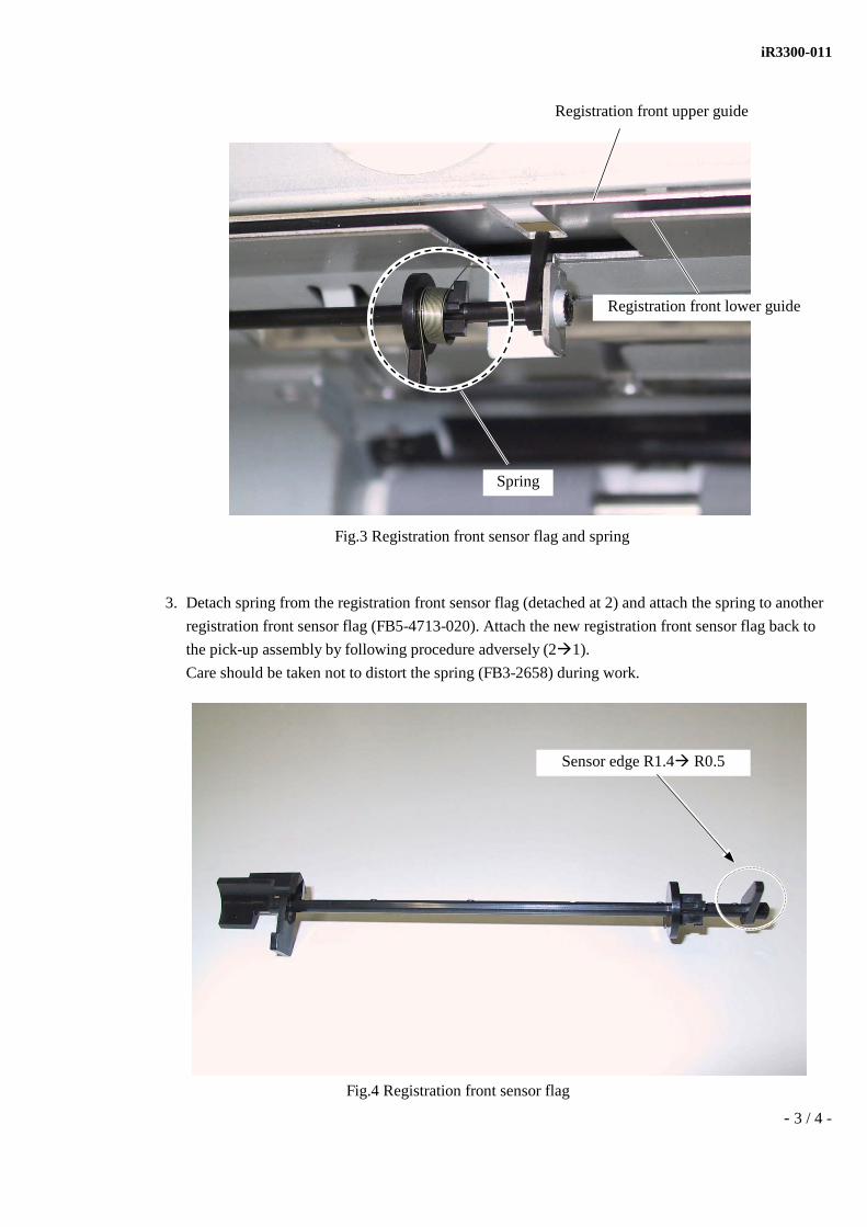
3. Detach spring from the registration front sensor flag (detached at 2) and attach the spring to another
registration front sensor flag (FB5-4713-020). Attach the new registration front sensor flag back to
the pick-up assembly by following procedure adversely (2 1).
Care should be taken not to distort the spring (FB3-2658) during work.
Spring
Registration front upper guide
Registration front lower guide
Fig.3 Registration front sensor flag and spring
Sensor edge R1.4 R0.5
Fig.4 Registration front sensor flag

iR3300-011
- 4 / 4 -
Service Parts:
P.C.No. Description Part number Q’ty
Inter-change-ability
1 Old PAPER PICK-UP ASSEMBLY FG6-5644-100 1→0 310-3
New PAPER PICK-UP ASSEMBLY FG6-5644-130 0→1
2 Old FLAG, REGIST, FRONT SENSOR FB5-4713-000 1→0 320-2
New FLAG, REGIST, FRONT SENSOR FB5-4713-020 0→1
Affected Machines:1. Positional adjustment for Registration Front Guide Assembly
Product name Product code Destination Serial NumberiR2200 6583A003BA 230V ITA PSQ00201 and lateriR2800 6379A007BA 230V ITA PST00196 and lateriR3300 6378A002BA 230V ITA PSS00021 and lateriR2200 6583A004BA 230V UK QEF00251 and lateriR2800 6379A009BA 230V UK QEH00476 and lateriR3300 6378A004BA 230V UK QEG00311 and lateriR2200 6583A006BA 230V FRN SDD00401 and lateriR2800 6379A010BA 230V FRN SDJ00701 and lateriR3300 6378A005BA 230V FRN SDF00250 and lateriR2200 6583A007BA 230V GER TDS00270 and lateriR2800 6379A011BA 230V GER TDU00811 and lateriR3300 6378A006BA 230V GER TDT00211 and lateriR2200 6583A008BA 230V AMS UHK01085 and lateriR2800 6379A012BA 230V AMS UHM01866 and lateriR3300 6378A007BA 230V AMS UHL00821 and later
2. New shape of registration front sensor flag
Product name Product code Destination Serial NumberiR2200 6583A003BA 230V ITA PSQ01251 and lateriR2800 6379A007BA 230V ITA PST00416 and lateriR3300 6378A002BA 230V ITA PSS05586 and lateriR2200 6583A004BA 230V UK QEF04561 and lateriR2800 6379A009BA 230V UK QEH02772 and lateriR3300 6378A004BA 230V UK QEG02236 and lateriR2200 6583A006BA 230V FRN SDD06716 and lateriR2800 6379A010BA 230V FRN SDJ02006 and lateriR3300 6378A005BA 230V FRN SDF02683 and lateriR2200 6583A007BA 230V GER TDS06230 and lateriR2800 6379A011BA 230V GER TDU01471 and lateriR3300 6378A006BA 230V GER TDT02157 and lateriR2200 6583A008BA 230V AMS UHK10590 and lateriR2800 6379A012BA 230V AMS UHM05257 and lateriR3300 6378A007BA 230V AMS UHL04901 and lateriR3300i 7468A009AA 230V AMS UJC00005 and later
No Yes
No Yes

- 1 / 7 -
Service BulletinIssued by Canon Europa N.V.
Model: iR2200/2800/3300 Series No.: iR3300-012
(FF-T01-L5-000037-01)
DATE: 30.08.02
Location: Lower Lifter Mount
Subject: Strange Noise Caused by Interference
Reason: Interference between lower lifter mount in pick-up assembly and vertical path roller in cassette feeding
unit-w1 may result in strange noise.
Detail:<Symptom>
At feeding operation, lower lifter mount and vertical path roller interfere each other, making strange
noise.
<Cause>
When machine is moved during or after its installation, rubber foots (XH9-0125) on the rear side in the
machine may come off each position. Because of this, the machine leans and loses adequate space
between the lower lifter mount and the vertical path roller (FB5-5403).
As a result, there is possibility to interfere each part as making strange noise. (see Fig.1)
It is also revealed that accumulation of the parts tolerance causes the interference.
COPIER
Interference occurs
Lower lifter mount Vertical path roller
Fig.1 Location in question

iR3300-012
- 2 / 7 -
<Factory Measures>
1. Shape change to Lifter Support Arm
To prevent interference with vertical path roller, lifter support arm that has more relief space has
been made.
Service Work:As for the symptom, check 1 first and then implement 2.
1. To make sure rubber foots presence.
2. To replace lower lift mount with lifter support arm
<1. Rubber foot Presence/Absence confirmation>
When rubber foots (XH9-0125) is detaching, the machine leans and there is possibility for the
interference, thus make sure its P/A by the following procedure.
1. To make sure presence or absence of rear rubber
foots.
1) Remove waste toner receptacle cover
attached on the left rear side of the main
body.
2) Be sure rubber foot (light gray)
(Use penlight if you need)
Rubber foot (light gray)
Old New
Fig.2 Lower lifter mount (old) and Lifter support arm (new)
Lower lifter mount
Lifter support arm
Relief space is added to preventinterfere with vertical path roller

iR3300-012
- 3 / 7 -
3) Detach rear side cover on the right of the main body.
4) Be sure rubber foot (light gray) (Use penlight if you need)
2. In the case of their absence, attach new rubber foots (XH9-0125) to each position. However, before
attaching the new rubber foots, work with more than 2people for detaching main body from cassette
pedestal.
Rear side cover
rubber foot(light gray)

iR3300-012
- 4 / 7 -
<2. Changing to lifter support arm>
The following procedure is to replace lower lifter mount (FB3-2889) with lifter support arm (FB6-4577)
1) Detach paper pick-up mount assembly.
(See Service manual chapter5 9.1.1 Detaching the paper pick-up mount assembly)
2) Stand the assembly (see Fig.4) and release screw (Tight screw M3x8 XA9-0591)
Fig.3 Paper pick-up mount assembly
Fig.4 Release screw on lifter lower mount

iR3300-012
- 5 / 7 -
3) Detach separation roller (lower) by picking and pulling its claw (see Fig. 5)
4) Detach lower lifter mount from lifter plate (FB6-2777) as lifting up, and detach compression spring
(FS6-2330) from lower lifter mount. (see Fig.6)
Care should be taken not to lose the compression spring during work.
Separation roller
Fig.6 Detach compression spring
Fig.5 Detach separation roller
Lifting up Lower Lifter Mount
Compression
Lifter plate

iR3300-012
- 6 / 7 -
5) Remove lifter plate (FB6-2777) as lifting it up. (see Fig.6)
6) Push separation roller holder slightly, and detach lower lifter mount as pulling it to the left.
7) Attach lifter support arm (FB6-4577)
8) Follow adverse procedure 5 1 for reassembling
Points to Note About Service Work:Make sure again if rubber foots (XH9-0125) are placed on right position after the installation above has
completed.
Service Parts:
P.C.No. Description Part number Q’ty
Inter-change-ability
1 Old PAPER PICK-UP ASSEMBLY FG6-5644-090 1→0 103-23
New PAPER PICK-UP ASSEMBLY FG6-5644-100 0→1
2 Old MOUNT, LIFTER SUPPORT (LOWER) FB3-2889-000 1→0 310-75
New ARM, LIFTER SUPPORT FB6-4577-000 0→1
Push separation roller holder (White)slightly with your right hand, and pulllower lifter mount with your lefthand.
Lower lifter mount
No Yes
No Yes
Fig.7 Detach lower lifter mount

iR3300-012
- 7 / 7 -
Affected Machines:Changing to Lifter Support Arm
Product name Product code Destination Serial NumberiR2200 6583A003BA 230V ITA PSQ00607 and lateriR2800 6379A007BA 230V ITA PST00221 and lateriR3300 6378A002BA 230V ITA PSS00941 and lateriR2200 6583A004BA 230V UK QEF01431 and lateriR2800 6379A009BA 230V UK QEH00606 and lateriR3300 6378A004BA 230V UK QEG00661 and lateriR2200 6583A006BA 230V FRN SDD01506 and lateriR2800 6379A010BA 230V FRN SDJ00802 and lateriR3300 6378A005BA 230V FRN SDF00391 and lateriR2200 6583A007BA 230V GER TDS01501 and lateriR2800 6379A011BA 230V GER TDU01026 and lateriR3300 6378A006BA 230V GER TDT00665 and lateriR2200 6583A008BA 230V AMS UHK03350 and lateriR2800 6379A012BA 230V AMS UHM02646 and lateriR3300 6378A007BA 230V AMS UHL01516 and later

(1/1)
Canon Service Bulletin COPIER
Issued by Canon Europa N.V.
Location:Controller BoxSubject:Doing away with Fan Motor
Model:iR2200iR2200iiR2800iR2800GiR3300iR3300i
Ref No.:iR3300-013 Rev. 2(FF-T01-L5-000045-03)Date:30-05-03

- 1 / 4 -
Detail: Because of doing away with the fan motor, the fan motor circuit on the main controller PCB is also
disused, thus the electrical elements are removed from the list of service parts.
Main controller PCB
Controller box
Fan motor

- 2 / 4 -
The blank connector (J1028) appears after the disuse of the fan motor, and attaches the shorting
connector (newly set up as a service part) to the blank connector.
To confirm the presence of the shorting connector easily, affix the shorting connector label to near the
shorting connector on the main controller PCB.
There will be no problem about the quality even after the fan motor in the controller box is disused.
Electrical elements
Electrical elements
Shorting connector
J1028
Shorting connector label
! J1027

- 3 / 4 -
Service Work:
" When attaching the new main controller PCB to the old controller box, detach the unnecessary fan
motor from the old controller box.
In addition, because J1027 is deleted from the new main controller PCB, there is no location to
connect the harness connector. However, a machine performs properly even if the harness connector
is unconnected, so do not connect the connector to anywhere on the new main controller PCB.
" Contrariwise, when attaching the old main controller PCB to the new controller box (not the fan motor
mounted), replace the shorting connector from the new main controller PCB to the old main controller
PCB.
<Notes>
In the case of not replacing the shorting connector, the alarm code (000804-0004) “ fan motor
malfunction” displays on the service mode (COPIER>DISPLAY>ALARM-2) though the machine
runs properly.
Service Parts:
P.C. No. Description Part number Q’ty
Inter- change- ability
1 Old MAIN CONTROLLER PCB ASSEMBLY FG3-1742-000 1→0 900
New MAIN CONTROLLER PCB ASSEMBLY FG3-1742-080 0→1
*1
2 Old MAIN CONTROLLER PCB ASSEMBLY FG3-2232-000 1→0 900
New MAIN CONTROLLER PCB ASSEMBLY FG3-2232-060 0→1
*2
3 Old 900
New SHORTING CONNECTOR FF3-4219-000 0→1
*1 *2
4 Old FAN FH6-1885-000 1→0 900
New
*1 *2
5 Old SCREW, MACH, TRUSS HEAD, M4X20 XB1-2402-007 2→0 900
New
*1 *2
*1: Interchangeability works as changing the 4 parts at the same time. (No1. No3. No4. No5)
*2: Interchangeability works as changing the 4 parts at the same time. (No2. No3. No4. No5)
Shorting connector label is not set up as service part.

- 4 / 4 -
Affected Machines: Model Destination Serial No. iR2200 230V AMS UHK16085and later iR2200i 230V AMS UJB00533 and later iR2800 230V AMS UHM07615and later iR3300 230V AMS UHL07271and later iR3300i 230V AMS UJC00514 and later iR2200 230V UK QEF06688 and later iR2200i 230V UK QEV00155 and later iR2800 230V UK QEH03248 and later iR3300 230V UK QEG03480 and later iR3300i 230V UK QEW00139 and later iR2200 230V GER TDS08011 and later iR2200i 230V GER TEG00150 and later iR2800 230V GER TDU01985 and later iR3300 230V GER TDT02341and later iR3300i 230V GER TEH00137 and later iR2200 230V FRN SDD08935and later iR2200i 230V FRN SDT00337 and later iR2800 230V FRN SDJ02644 and later iR3300 230V FRN SDF03652 and later iR3300i 230V FRN SDU00196and later iR2200 230V ITA PSQ01252and later iR2200i 230V ITA QSZ00034and later iR2800 230V ITA PST00452 and later iR3300 230V ITA PSS05586 and later iR3300i 230V ITA RSC00021 and later

- 1 / 2 -
Service BulletinIssued by Canon Europa N.V.
Model: iR2200/2800/3300 Series No.: iR3300-014
(FF-T01-L5-000035-01)
DATE: 27.09.02
Location: DC Controller PCB Assembly
Subject: Masking Flash DIMM-ROM of DC Controller PCB Assembly
Reason: For manufacturing reasons, masking Flash DIMM-ROM of DC Controller PCB was carried out.
Detail: The contents of Flash DIMM-ROM will be masked and masked ROM (IC301) will be attached
directly to DC Controller PCB. Therefore, Flash DIMM-ROM of DC Controller will be abolished.
Former Socket (J322) of Flash DIMM-ROM is empty. With the deletion of the flash DIMM-ROM, the
part number of the DC controller PCB remains unchanged.
Points to Note About Service Work:Former Flash DIMM-ROM will continue to be available as a service part.
COPIER
DC Controller PCB Assembly
Mask ROM (IC301)Empty socket (J322)
Flash DIMM-ROM(New DCON does not have it.)

iR3300-014
- 2 / 2 -
Affected Machines:Model Destination Serial No.iR2200 230V AMS UHK16240 and lateriR2200i 230V AMS UJB00670 and lateriR2800 230V AMS UHM07765 and lateriR3300 230V AMS UHL07336 and lateriR3300i 230V AMS UJC00584 and lateriR2200 230V UK QEF06898 and lateriR2200i 230V UK QEV00248 and lateriR2800 230V UK QEH03374 and lateriR3300 230V UK QEG03579 and lateriR3300i 230V UK QEW00177 and lateriR2200 230V GER TDS08011 and lateriR2200i 230V GER TEG00198 and lateriR2800 230V GER TDU01985 and lateriR3300 230V GER TDT02395 and lateriR3300i 230V GER TEH00172 and lateriR2200 230V FRN SDD09374 and lateriR2200i 230V FRN SDT00342 and lateriR2800 230V FRN SDJ03038 and lateriR3300 230V FRN SDF03951 and lateriR3300i 230V FRN SDU00256 and lateriR2200 230V ITA PSQ01342 and lateriR2200i 230V ITA QSZ00040 and lateriR2800 230V ITA PST00459 and lateriR3300 230V ITA PSS05640 and lateriR3300i 230V ITA RSC00041 and later

Canon SERVICE BULLETIN COPIERIssued by Canon Europa N.V.
MODEL: iR2200i, iR2800i, iR3300I No.: iR3300-016 Rev. 1
Date: 22.11.02
SUBJECT: LANGUAGE FILE HAS BEEN MODIFIED
Introduction:The language file of Finnish, Swedish, Norwegian and Slovenian has been modified. Accordingly, thisfile is uploaded on the web site,
URL : http://cgn.canon-europa.com/tss/tdd/copier/ir_system_cd.htm ←
Reason:The Jam and Cover Open messages have been revised from English into local languages.The object files are Swedish, Finnish, Norwegian and Slovenian
Version configurationModel Name File name Previous
versionconfig.
Latest version config.
iR2200i System software version 05.04 <---iR3300i Danish 05.04 <---iR2800i Swedish 05.04 05.05
Finnish 05.04 05.05Norwegian 05.04 05.05
Language Dutch 05.04 <---file Spanish 05.04 <---version Portuguese 05.04 <---
Greek 05.04 <---Slovenian 05.04 05.05Hungarian 05.04 <---Polish 05.04 <---Czech 05.04 <---Estonian 05.04 <---Russian 05.04 <---

- 1 / 4 -
Service BulletinIssued by Canon Europa N.V.
Model : iR2200-3300/2200i-3300i No.:
DATE:
iR3300-017
(FF-T01-L5-000011-02)
25.10.02
Location : Hard Disk Drive
Subject : Information of E602 troubleshooting
Reason : This bulletin notifies of servicing procedure to be followed if E602 error (HD-related error) occurred on an
iR machine
Details :E602 errors on iR machines are classified into the following errors by the subcode and corresponding cause:
(1) E602-0001A HD mount error was detected when the HD was started up.
(2) E602-0002A HD data read error was detected when the HD was started up.
(3) E602-0003
The data address registered on the HD is not consistent with the data. (Write-abort error on HD sector)
(4) E602-0004An error occurs by checking the Control Table of “Image storage area” when the machine is “ON”.
(See Note: 3)
Trouble shooting of each sub code is as follows.
(1) E602-0001
Check the faulty connection between the HDD and the main controller PCB
Poor HDD : Replace the HDD, and reinstall System Software
Poor Main Controller PCB : Replace the main controller PCB
(2) E602-0002
System Software is not installed properly : Reinstall System Software
COPIER

iR3300-017
- 2 / 4 -
(3) E602-0003
The following 4 partitions exist in the HDD of the iR models, and countermeasure differs depending
on whether Write-Abort occurs in the area.
(Note) Partitions on iR machine
1) Image storage areaSaves and stores image data.
2) General-purpose file storage areaStores user setting data, various log data, PDL spool data, and image data address.
3) PDL-related file storage areaStores font data for printers.
4) Firmware storage areaStores system software.
(a) If write to the image storage area was abortedA function is implemented to fix a write-abort error in the image storage area, which automaticallyrepairs the error after power is turned off and switched on again. (The function writes dummy data atlocations specified by the data pointer to fix address-data inconsistency.)If a write-abort error occurred in the image storage area and E602-0003 is output, turn off the mainpower and then turn it on again to fix the error. (See Note 1.)
(b) If write to other areas than the image storage area was abortedIf write to other areas than the image storage area was aborted, the automatic recovery function is unableto fix it. Follow the procedure below to manually recover the sector.
(i) If the machine can be entered service mode- Enter service mode and set "0" for COPIER > FUNCTIONS > SYSTEM > HD-CHECK.(This will check and recover the entire sectors on the HD.) (This takes about 20 to 40 minutes depending onthe HD capacity.)- After executing HD-CHECK, turn the power off and turn it on again to check that the HD starts upnormally. If the HD fails to start up, set "1" and then "2" for HD-CLEAR. ("1" initializes the image storagearea; "2" the general-purpose file storage area.)- After recovering from the write-abort error, reinstall system software. (System reinstallation isrecommended, as there is possibility that the sector fails to return in a proper state afterauto-recovery of Write Abort sector)
(ii) If the machine cannot enter service modeE602-0003 may appear after power-on on a machine in a state incapable of entering service mode.(This occurs if write-abort error is detected during self-diagnosis after power-on.)In this case, turn on the main power while holding down digit keys 1 and 9 at the same time. Thisactivates a function that is equivalent to setting "0" for HD-CHECK in service mode.After calling up the function, see "If the machine can enter service mode" above and do as you doafter entering service mode.
(4) E602-0004(a) In case recovery is possible, indicate the service error E602-0004 on the screen once, and turn“OFF” and “ON” the machine to recover(b) In case recovery is impossible, the service error E602-0004 appears all the time on the screen :Replace the HDD and reinstall System Software

iR3300-017
- 3 / 4 -
Remarks :(1) Causes of write-abort errors
As a rule, write-abort error results from inconsistency between the address (data pointer) and the data.The address-data consistency is broken by turning power off at illegal timings.
iR machines access their HD at the timings below, not to mention when copying and/or writing of PDL data.If the main power is turned off coinciding with any of the following events, the E602-0003 error occurs.
i) 150 ms of initial process within 1 minute after a jobAn iR machine performs internal process in the main unit for a duration of 150 ms at undetermined timingwithin 1 minute after completion of a copy/fax/print job. (During the internal process in the main unit, thecontroller accesses the image data address files on the HD.)
At what point in the 1-minute time span the process starts is undetermined. If the main power is turned onduring the 150 ms, The E602-0003 code may appear when the power is turned on next time.
ii) 19 ms of inquiry from NetSpotIf an inquiry for job history information is sent from NetSpot on a PC to the copier, the HD makes writingoperation for about 19 ms. Turning off the main power within this duration may cause E602-0003 when the poweris turned on next time.
iii) Operation of remote UIThe HD makes writing operation also when remote UI is working. Turning off the main power within the durationmay cause E602-0003 when the power is turned on next time.
(2) Maintenance functions in service modeChecking and initializing the whole HDD or each partition of the 4 are possible from the followingmenus in service mode.
COPIER->FUNCTION->SYSTEM->CHK-TYPE : Specifying affected areaCOPIER->FUNCTION->SYSTEM->HD-CHECK : Checking HDD or partitionsCOPIER->FUNCTION->SYSTEM->HD-CLEAR : Initializing partitions
CHK-TYPE HD-CHECK HD-CLEAR
0(The whole disk) Faulty sector check and recovery (No function)
1(Area to accumulate image) Compatibility check Initialization
2(Area to store general-purpose files) Compatibility check Initialization
3(Area to store PDL related files) Compatibility check Initialization
4(Area to store Firmware) Compatibility check (No function)Operation Procedure: Follow the chart above, and specify the area you wish to process with
CHK-TYPE. Carry out HD-CHECK when checking compatibility,and HD-CLEAR when performing initialization.
※ System reinstallation is recommended after auto-recovery of sector with HD-CHECK(CHK-TYPE=0), as there is possibility that sector fails to return in a proper state.※ If initializing “Image storage area” is carried out with HD-CLEAR (CHK-TYPE=1),all images accumulated in HDD are deleted.
(3) Prevention measures against E602-003/004It is recommended to turn “OFF” the control panel, and put the machine in sleep mode beforeturning “OFF” the main power as prevention measures against E602-003/004. (for reduce the HDD load)

iR3300-017
- 4 / 4 -
Cautions :(1) Note 1: Automatic recovery from write-abort error in the image storage area by main power off/on
This function is supported by the following versions of system software:iR2200 : v6.01 or laterOther models : Initial mass-production versions
(2) Note 2: Recovery of sectors by holding down 1+9 during power-onThis function is supported by the following versions of boot ROM:
v7.25
(3) Note 3: About E602-0004As a result of the report “Incapability of booting up caused by HDD trouble” from the field,it was found out that the Control Table of “Image storage area” had been crashed.In case the Control Table is crashed, abnormal operations occur when checkingcompatibility during boot-up or when accessing files after boot-up.To reinforce prevention of the abnormal operations, software is modified to process thedetailed check of the control table of “Image storage area” when the machine is “ON”.The indication appears if an error occurs during the check.
This function is supported by the following System Software versions or later:iR2200-3300 : v31.04 or laterOther models : supported from version manufactured at the initial volume production

(1/30)
Canon Service Bulletin COPIER
Issued by Canon Europa N.V.
Subject:
New Models information (iR2220i/3320i/3320N)
Reason:
A group of new machines will soon be introduced. They will come equipped with MEAP functions, and differ from
existing models (iR2200i/3300i) as described in this bulletin.
Description:
1.Major Differences
a.Hardware-Related Differences
- The size of the SDRAM (work memory) that comes standard on the main controller PCB has been increased from
192 MB to 256 MB. (2 memory slots -> 1 memory slot)
- The size of the boot ROM has been increased from 1 MB to 2 MB to support network downloading.
- Changes have been made to the counter memory PCB so as to accommodate increases in capacity. (no compatibility
with existing models)
- A change has been made so that the name of the service system used at time of downloading is now "iR2220."
- An option has been made available to support MEAP USB applications; i.e., MEAP Application Interface Board-
B1 (8749A001AA). The board is to be added when using an MEAP application that supports USB peripherals. It
serves no purpose in the absence of a MEAP application. The board adds 2 extra Series A connectors for upstream
equipment.
- An option has been made available to support the use of MEAP functions; i.e., Resolution Switching Board-C1
(8731A001AA). It must be added when using a MEAP application that requires it.
b.Functional Changes Not Related to MEAP
Major changes are in relation to the iR C3200's SEND function. Herein, the iR2200i are used as reference machines
when describing the SEND function.
Important!
iR C3200 is called CLC3200 in Europe.
- Reboot Function from NetSpot Console, NetSpot Device Installer, Remote UI
This function is a newly added function (absent in existing models including the iR C3200).
Model:
iR2220iiR3320iiR3320N
Ref No.:
iR3300-019
(F1-T01-0L5-10011-02)
Date:
29-08-03

iR3300-019
(2/30)
With this function, the machine may be started remotely after changes have been made that require restarting of the
machine. All future machines are expected to possess this function. (This function cannot be used without assigning
a system administrator.)
- Saving Job Histories in csv Format
This function is new with the machine (absence in existing models including the iR C3200).
With this function, individual job histories may be saved in csv format using the remote UI.
- LDAP
The machine also comes with LDAP (Light-Weight Database Access Protocol), which was introduced with the iR
C3200. The machine offers access to the server database for information on targets of transmission. If the address is
a new one and transmission is by direct reference to an LDAP server address, the machine's resources will limit the
number of targets to 16, unlike the iR C3200, which permits broadcasting to as many as 64 targets.
- Preview
This function came first with the iR C3200. The machine differs from the iR C3200 in that its preview function offers
a choice of deleting the page.
- Priority on E-Mail Transmission
This function came first with the iR C3200. The machine offers 3 settings (high, medium, and low, with the default
being medium).
- Single Page PDF
This function is new with the machine (not found in existing machines, including the iR C3200). The machine offers
a new button for division into individual pages (as done with TIFF); the machine now offers a choice between single
page and multi-page in addition to the choice between TIFF and PDF.
- Forwarding
The specifications have been modified so that they are now identical to those of the iR C3200. With the newly added
following functions, making transfer settings has been made simpler:
transfer in the event of a mismatch in conditions storage of a transfer error file in the system box end-of-transfer
notice limited to transfer error transfer processing timer call key priority setting for e-mail transfer
- Support of 2-Byte Code for FTP File Names and Addresses
The specifications have been modified so that they are now identical to those of the iR C3200. (This function is not
found in the iR2200i.) This function is Japanese language model only.
An addition has been made to the user data so that it now has "permit non-ASCII code for FTP transmission". It is
important to remember that, although the FTP file name may be of 2-byte code, it cannot serve its function unless
the FTP server supports the use of the code.
- Routine Task Key Screen
This is a newly added function, not found in existing machines including the iR C3200.
The function is used to enlarge the area of the routine task key.

iR3300-019
(3/30)
- Sender Field (for e-mail/i-fax transmission)
If authentication is used as part of the MEAP log-in service, the appropriate sender e-mail address that has been set
up in advance will be entered in the sender field.
In the case of SDL, the appropriate user name and e-mail address will be indicated in the MEAP user registration
page.
In the case of SSO, on the other hand, the log-in name (domain) and mail address will be indicated (from the domain
user information).
If the transmission does not require authentication (e.g., forwarding), however, the field will not be prepared (the
information selected as native information will be used).
With the addition of this function. the said information will be indicated in the transmission log and reception log
using the said format. It will also be indicated in the body text as sender information (only if the sender field exists
at time of transmission).
- Display on the Mail Application
The information will be added to precede the mail address (authenticated user name; display name/domain user name
(abbreviation));
e.g., from:user1<[email protected]>
user name as used for MEAP log-in authentication (display name)
In the case of SDL, the name from MEAP user registration will be indicated.
In the case of SSO, the domain user name will be indicated.
- SMB/FTP/NCP Transmission
When MEAP authentication is used, the login-in user name will be indicated in the transmission history; i.e., the date/
time column of the communications report will have a list of log-in user names for reference.
- Authentication at Time of Transmission
The machine supports NTLM authentication (NTLM 0.12)/use of long file names.
The specifications have been modified so that they are identical to those of the iR C3200. This function is absent in
the iR 2200i.
At time of SMB transmission, NTLM-based encrypted authentication is supported in place of natural language
authentication.
Because of the change, transmission is now possible using the user right (of the selected domain; by specifying
'domain name/user name' as the user name for file transfer). It is also possible to send to a common folder in access
mode at the user level of Win 9x. The function supports the use of a long file name, which previous models fail to
display.
Important!
Unlike in the previous models, this function may permit transmission to a folder based on SAMBA of NAS (Network
Attached Storage) or Linux. Since the use in all environments cannot be guaranteed, be sure to run a test in the user
environment before delivery.
iR3300-019
(4/30)
c.MEAP
<What is MEAP?>
MEAP stands for "Multifunctional Embedded Application Platform", and is a software platform often built into a
peripheral device (e.g., MFP). MEAP is based on Java (J2ME: Java 2 Platform Micro Edition), and is intended to
run a Java application (i.e., MEAP application). Any MEAP application is independent of the device system software
and, as such, it may be installed or uninstalled using SMS (Service Management Service), which is a browser-based
interface on a PC) as long as the device supports the use of MEAP, permitting the addition of MEAP applications in
the field.
<Major Feature of MEAP>
- It enables the development/customization of an application that suits various user needs (making way for
remarkable software possibilities).
- It offers counters for prints and scans for individual applications so that new business models may be set forth with
added versatility to existing charging methods.
- It permits connection of USB devices to match applications in use (2 ports; MEAP-specific options).
- It permits the addition of applications (thus increasing added value) to a MEAP machine in the field on a continual
basis (thus increasing the competitive edge).
- It permits as many as 19 MEAP applications to run all at once. (If to be placed under the control of the local UI, 9
applications (applets) may run at the same time.)
At time of shipment from the factory, the machine is ready to run 18 applications to run all at once; i.e., 1 of the 19
applications is used by the portal service (pre-installed; used to link the remote UI and MEAP service applications;
may be uninstalled; described later).
<Organization of MEAP P/F>
In addition to the system software, language, and remote UI files, a copier equipped with MEAP functions requires
the installation of MEAP content files designed to enable functions (system services) needed to run MEAP
applications and class libraries used by the MEAP applications to control the device.
The version of the system software and the version of MEAP content files must be in keeping with each other, calling
for care to avoid malfunction of MEAP functions otherwise occurring as the result of a Mismatch. Appropriate
information will be found in the Service Information bulletin to be released to coincide with the release of a system
CD.

iR3300-019
(5/30)
The following is a diagram of MEAP viewed in its relation to its component entities.
MEAP platform
figure 1
<MEAP Application and Counter>
In addition to the existing copy counters, a MEAP-based device offers MEAP counters that may be used to find out
how much of the functions have been used according to individual MEAP applications. The readings of the MEAP
counters may be checked by pressing the Counter Check key on the copier's control panel and then selecting a check
on the counter reading.
The following table shows the MEAP counters; which counters to use depends on the specifications of the
application in question. An invoice may be prepared for scanning and printing by taking advantage of these counters.
(Some Sales Companies may opt to prepare a period-based contract instead of a counter-based contact.)
iR3300-019
(6/30)
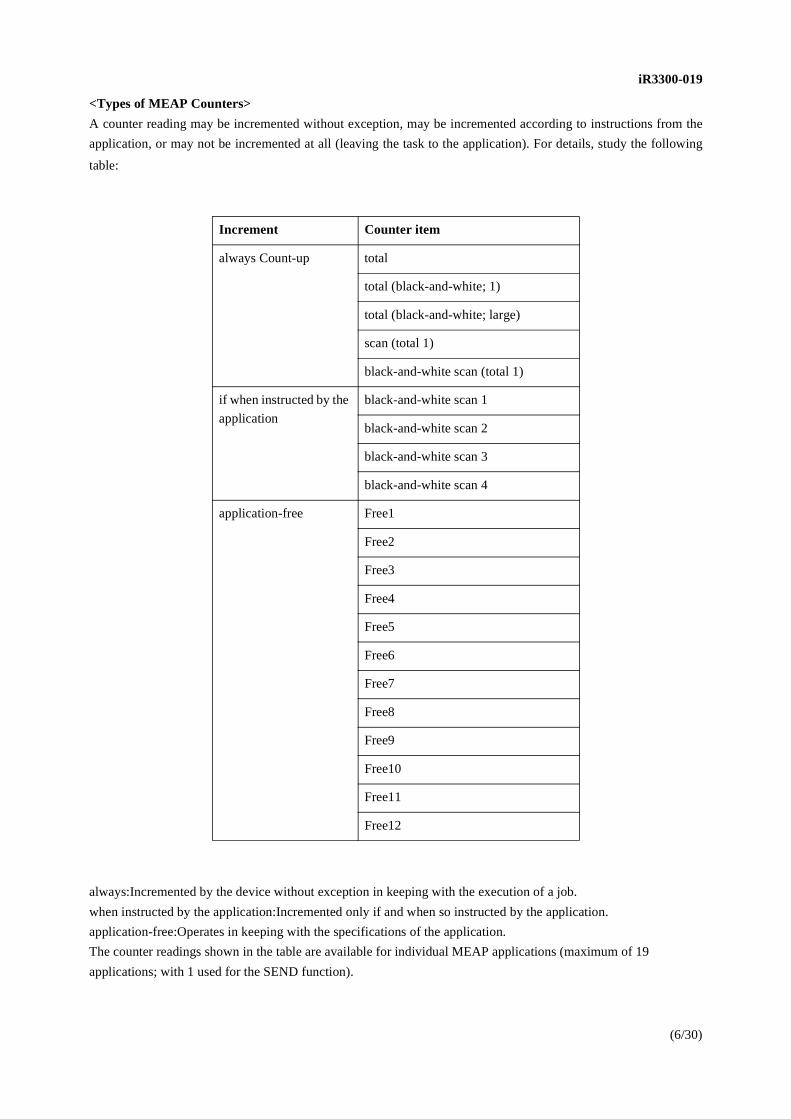
<Types of MEAP Counters>
A counter reading may be incremented without exception, may be incremented according to instructions from the
application, or may not be incremented at all (leaving the task to the application). For details, study the following
table:
always:Incremented by the device without exception in keeping with the execution of a job.
when instructed by the application:Incremented only if and when so instructed by the application.
application-free:Operates in keeping with the specifications of the application.
The counter readings shown in the table are available for individual MEAP applications (maximum of 19
applications; with 1 used for the SEND function).
Increment Counter item
always Count-up total
total (black-and-white; 1)
total (black-and-white; large)
scan (total 1)
black-and-white scan (total 1)
if when instructed by the
application
black-and-white scan 1
black-and-white scan 2
black-and-white scan 3
black-and-white scan 4
application-free Free1
Free2
Free3
Free4
Free5
Free6
Free7
Free8
Free9
Free10
Free11
Free12
iR3300-019
(7/30)
<SEND Function and MEAP Counter>
The SEND function was used by a non-MEAP machine in relation to the number of scans made. A MEAP machine
offers a counter for the SEND function; this counter is treated as a MEAP application, but cannot be installed/
uninstalled as an application because the SEND function is hardwired to the device (as a native function).
When the SEND function is used, the readings are incremented as follows:
<Counter History>
As many as 20 readings are generated by the MEAP counters (including the reading used by the SEND function); no
additional counter readings can be created. If a MEAP application is removed, its counter reading will be retained on
the hard disk in the form of a "counter history." A total of 24 histories may be kept at a time; however, if 20 MEAP
counters exist (including any histories occurring as a result of removing applications), only 4 may be used for
additional histories.
<MEAP-Related User Mode/Service Mode>
The following changes have been made as a result of the support of MEAP functions:
User Mode
- A user mode item has been added to permit turning on/off of the MEAP HTTP server (port 8000): System
Settings>MEAP Settings>Use HTTP.
- A user mode item has been added to enable printing of a report on the installed MEAP applications: System
Settings>MEAP Settings>Print System Infomation. It is important to keep in mind that this mode item cannot be
used in the absence of a PDL function.
- A user mode item has been added to enable using MEAP as the Initial screen: Common Settings>Initial
Function>Select Initial Function>MEAP.
Service Mode
- A service mode item has been added to enable checking the version of Java VM:
COPIER>DISPLAY>VERSION>Java-VM.
- A service mode item has been added to enable checking the version of MEAP contents:
COPIER>DISPLAY>VERSION>MEAP.
- A service mode item has been added to enable checking the connection of a MEAP application interface board-B1:
COPIER>DISPLAY>ACC-STS>USB-host.
1: iR2200i/2800i/3300i series board connected; 2: iR5000/6000 series board connected
black-and-white total scan 1 all SEND scans including faxing and i-faxing
black-and-white scan 1 box scan, e-mail, FTP, SMB, NCP, send-to-box
black-and-white scan 2 e-mail, FTP, SMB, NCP
black-and-white scan 3 FTP, SMB, NCP
black-and-white scan 4 Box scan, FTP, SMB, NCP, send-to-box

iR3300-019
(8/30)
- A service mode item has been added to permit initialization of the display, used when a switchover of languages
causes the text of transmission/fax read settings to become garbled: COPIER>FUNCTION>CLEAR>SEND-STUP.
The device must be restarted after clicking [OK].
<Functions of SMS>
SMS has the following functions:
- installs/uninstalls a MEAP application from a PC on the network.
- starts/stops a MEAP application that has been installed.
- enables/disables a license file that has been installed.
- checks information on a MEAP application that has been installed.
- changes the order of applets that have been installed for display.
- installs/uninstalls the system application.
- starts/stops the system application.
- sets up/uninstalls the log-in service.
- checks MEAP system information.
- checks information on the license file (before installation)
- changes the log-in password to SMS.
For details of SMS, see the MEAP SMS Administrator guide.
<Access to SMS>
SMS is a Web application with its URL being http://IPaddress:8000/sms. Upon a visit, a message will appear,
prompting input of a password; SMS functions are offered in response to a successful log-in.
<MEAP-Compatible Browsers>
A MEAP device requires browsers of the following types. Take care, as an SMS client environment is under stricter
restrictions than remote log-in and RemoteUI environments.
Client Environment Need for the SMS
(JavaScript must be enabled)
Windows 98SE
IE 5.5 SP2/IE 6 SP1
Windows 2000 Professional SP3
IE 5.5 SP2/IE 6 SP1
Windows XP Professional/Home Edition
IE 6 'Gold'/IE 6 SP1

iR3300-019
(9/30)
Default Authentication and Client Environment (SDL remote log-in, RUI, Portal Service)
(JavaScript must be enabled)
Windows 98SE/NT4.0 SP6a
IE5.01 SP2/IE5.5 SP2/IE6 SP1
Windows Me
IE5.5 SP2/IE6 SP1
Windows 2000 Professional SP3
IE5.01/IE5.5 SP2/IE6 SP1
Windows XP Professional/Home edition
IE6 'Gold'/IE6 SP1
for the foregoing Windows environments, Netscape 4.61 through 6.2.3
Mac OS 8.6 through 9.X
IE5.0 through 5.1.6
Mac OS 10 through 10.2.4
IE5.2.2
<Log-In>
To use SMS, type in the appropriate password on the Log-In page. Make sure that the password is the one set up
initially as 'MeapSmsLogin'. (It is case sensitive.)
Simply type the password in the Password field of the Log-In page, and click [log in]. You will not be able to log in
if SMS is already in a log-in state as in the following cases:
- another user has already logged on to SMS.
- the browser has previously been closed without a log-out operation (i.e., SMS is waiting for a time-out to occur
expected in about 15 min).
If an attempt is made to access SMS from a different browser while a log-in has already been made, the Log-In page
will appear but the attempt will fail even if the password is correct.
If the message 'Type Password' appears on the Log-In page in spite of input of a correct password, the browser
settings (e.g., Java script setting is disable.) may not be in keeping with SMS operating conditions. It is also important
to keep in mind that access by way of a proxy has not bee verified; as necessary, remove the device IP addresses from
the list of addresses for which the use of the proxy is specified.

iR3300-019
(10/30)
SMS Login
figure 2
If the attempt to log in fails because of input of the wrong password, there will be a message asking for the correct
password. In addition to the message "Password is incorrect. Enter correct password." there will be an area for a
license file used to initialize the password to 'MeapSmsLogin'. (A separate communication will be issued for
instructions on how to obtain a license file used to initialize SMS password.) As a matter of course, access to SMS
will be given in response to an appropriate password entered in the input text field.
iR3300-019
(11/30)
Login error
figure 3
<Installing a MEAP Application>
A MEAP application may be installed from the Application Install screen through a browser. To do so, both the
MEAP application file (jar file; filename.jar) and the license file (filename.lic) must be copied at the same time. The
jar file is in compressed form, decoded only with the use of its ID key that comes with the license file. The license
file itself also calls for an ID key (hardwired to the device) for decoding, thus preventing illegally making a change
to the file.
The license file contains information needed to install MEAP applications: serial number of the device (to prevent
illegal copying), period and number of uses (e.g., without a limit, with a limit on the period, with a limit on the
number of users), application ID (for identification of applications). These pieces of information are used to protect
against illegal copying and uses beyond imposed limits. The MEAP counter used to control the period/number of
uses holds current reading and upper limit data, offering a choice of disabling operations beyond limits.

iR3300-019
(12/30)
Installation of MEAP Application
figure 4
<Invalidating the License File>
To remove a license file from the device (once it has been installed), the file must be invalidated using the
Application Information screen of SMS.
To invalidate the license file, the application must be stopped.
To uninstall the application, the license must be invalidated.
A click on [invalidate] will create a license file inside the device as a completely new license. An invalidated license
will be indicated as an icon on the screen, which may be downloaded to a PC or removed from it. (Take care not to
inadvertently remove an invalidated license that has been downloaded to the PC inadvertently; otherwise, you will
have to purchase a new license.)
The license that has been invalidated and downloaded to a PC may be installed back to the MEAP device from which
it has been removed; this is a consideration made to enable uninstalling of a MEAP application for checks in the event
of a fault during service work. The file, however, cannot be installed to a different MEAP device. If limits (in terms
of a period or number of uses) are imposed on the application in question, the balance (remaining length or uses) will
be written to the invalidated license so that the user will have the full remaining use after reinstalling the application
using the invalidated license file.

iR3300-019
(13/30)
<Portal Service>
Thanks to the support of MEAP, an iR device can now accommodate multiple MEAP applications (known as
"servlet") that may be used through a Web browser from a PC (as in the case of the SMS and in addition to the use
of a remote user interface). To show these applications in a browser, each application must be identified by its own
URL. Portal Service is a collection of services, one of which offers a list of application URLs to free you from having
to type in individual URLs.
Portal Service is pre-installed, and may be accessed by the following URL:
http://IPaddress:8000/
Moreover, the link to Portal service is also prepared for RUI top page.
Simultaneously with installation, Servlet type Application is designed so that a link may be automatically registered
into Portal Service. The link of RemoteUI is registered by the default. The link button to the "Sys. Admin
applications" is also prepared for Portal Service in addition to the link to Application. If "Sys. Admin applications"
button of Portal Service is clicked when SDL is chosen as login service, user management page of SDL mentioned
later will be displayed.
Portal Service
figure 5
<MEAP Login>
MEAP supports the following log-in services; in addition to the existing group-based control, it provides log-in
authentication to certify individual users. To use the log-in function, select any of 3 choices by making the following
selections: SMS>system control>expansion system application>log-in service.
1.default authentication (department ID control)
2.SDL (Simple Device Log-In)
3.SSO (Single Sign-On) Log-In

iR3300-019
(14/30)
SDL and SSO are installed as system applications so that they may be removed if there is no need for them from
SMS. (On the other hand, there is no need for uninstalling them.)
For details of the MEAP log-in service, see the attached file to MEAP SMS Administrator Guide.
The following is the Selection screen for SMS log-in service:
Selection of Login service
figure 6
<Default Authentication>
The default authentication function is used to provide some of the existing functions: "no authentication" (i.e., no
log-in screen will be shown) ad "Department ID management". If the user wants to have the existing authentication
environment (i.e., no authentication or group ID control), this will be the appropriate choice. (This also is the default
setting.)

iR3300-019
(15/30)
If the group ID control mechanism has been enabled, there will be a dialog used to prompt registration of an ID
number when logging into the local UI or the remote UI. It is also possible to use a Card Reader-C1 in place of input
of a group ID, in which case the installation will be as is done in the past.
<SDL>
SDL is a log-in service that holds such authentication data as user names and passwords within the device, and it
does not require another MEAP application or outside server for operation. In SDL, authentication is based on user
names and passwords, and as many as 1000 users may be put under control.
SDL is a type of user authentication application, and has the following functions:
1.shows a Log-In screen on the local UI for user authentication.
2.shows a Log-In page in the Web browser for user authentication.
3.edits user authentication information on the Web browser.
4.operates in conjunction with the group ID control mechanism to keep track of the number of print pages and scan
pages.
5.operates in conjunction with NetSpot Accountant to import/export user information and to collect, analyze, and
control device use information according to users.
The conceptual figure of SDL
figure 7

iR3300-019
(16/30)
<Introduction of SDL>
Before introducing SDL, it is important to be sure of the following:
(1)how SDL users will be registered
Normally, access is made through a browser to the SDL User Register/Edit screen to register/edit users. It is
necessary to decide in advance which users may be given the right to register/edit users. Those users who will be
serving as administrators must be registered as such; access may be made using the following URL: http://
deviceIPaddress:8000/sdl. The log-in screen for SDL will appear in response, asking for log-in as an administrator
user. If log-in is made as a general user, there will be an error message to indicate that the screen is not available and
that log-in as an administrator is required. The User Register/Edit screen permits the following:
- register/edit/delete user information
- import/export user information
- set the number of log-in histories to be displayed on the control panel at time of log-in
The example of the user edit screen of SDL is shown below.
SDL User Management page
figure 8
iR3300-019
(17/30)
In addition to manually registering users through a browser, user information of an SDL format (LDIF) from another
device may be imported or user information of an NSA format (csv format) from NetSpot Accountant Server may
be imported. For details of the User Register/Edit screen, see the attached Guide to MEAP Authentication System
Settings (included with the device).
At time of shipment from the factory, the following user accounts are registered:
user name: Administrator
password (user name): password
group ID: 0000000
password (group ID): 0000000
user type: administrator
display name: Administrator
phonetic: (for Japanese) left blank
e-mail address: left blank
card ID: (for Card reader-B1) left blank
Points to Note When Importing/Exporting User Information
SDL user information may be imported or exported, and you need to keep the following in mind when doing so:
- user types are not exported; when they are imported, the users will all be registered as general users.
- if the same user name already exists, the existing name will be replaced with the name being imported.
The following 2 methods may be used. Use the one better suited to the nature of the work.
Simple Device Log-In format
This is a method exclusively prepared for the SDL, and is written in compliance with the LDIF (LDAP data
interchange format; based on RFC2849). The user information and the address information differ from each other,
not compatible with the information in the files exported from the Address Book of an iR machine. It assumes sharing
MEAP SDL user information among multiple devices and using the information for backup purposes.
If 'person' is used for 'object class' of a record, the information is user information; on the other hand, if 'canon card'
is used for 'object class', the information is card ID information. The user passwords are encrypted for export,
department passwords are exported without encryption.
NetSpot Accountant format
It is a format used for the exchange of information with the NSA, and the data is stored using a csv format. All
passwords will turn blank at time of export, requiring new input at the destination.
The following shows how individual items are imported/exported:

iR3300-019
(18/30)
SDL import Specification
*1:If multiple cards are assigned to a single department ID, use the # symbol to divide individual pieces of
information within a single field.
No. NSA item Re-quired
Data constraints Default setting
Data registered with SDL
1 Parent Department
ID
O
not registered
2 Account type O not registered
3
Account ID
O numerals of 8 bytes max.;
however, 8th character must
always be '0', which otherwise
would cause the entire record
to be ignored
department
ID/user name
4
Account name
O only initial 32 characters are
valid display name
5
Password
numerals of 7 characters max.
(no 2-byte characters)
null department
password/
password
6 E-mail address 48 bytes max. null e-mail address
7
Log-in name
character string of 24 bytes
max.
null either log-in
user name or
computer
name, as set up
at time of
import
8
Domain name
character string of 24 bytes
max.
null
not registered
9 print usage limit numerals of 9 bytes max no limit not registered
10
card ID numeral of 8 bytes assumed
not
assigned
card ID*1
11 card password not generated null not registered
12 print usage limit by
card numerals of 9 bytes max. no limit not registered
13 actual usage numerals of 9 bytes max. not registered

iR3300-019
(19/30)
SDL export Specification
*1:If multiple cards are assigned to a single department ID, use the # symbol to divide individual pieces of
information within a single field.
No. NSA item name Quotationmarks
Description Data exported from SDL
1 Parent
department ID
always 0
(immediately under
route)
always 0
2 by account type always 1 (always
user)
always 1
3 account ID 7 characters max. (no
2-byte character)
SDL department ID
4 account name O character string of 32
bytes max.
display name (if omitted, log-in user
name)
5 password always blank always blank
6 e-mail address O character string of
256 bytes max.
e-mail address
7 log-in name O character string of 32
byte max.
log-in user name
8 domain name O always "" always ""
9 print upper limit always blank always blank
10 card ID numerals of 8 bytes
assumed
card ID*1
11 card password always blank (no
comma generated
hereafter)
always blank
12 print upper limit
by card
not generated not generated
13 actual value not generated not generated

iR3300-019
(20/30)
(2) if department ID control is to be used side by side
If, for instance, statistics are to be compiled in conjunction with department ID control, a department ID and
password must be registered for each user to link the user with the department ID set up on the device. The control
mechanism on department IDs and passwords is dependent on the department ID control mechanism of the device,
not that of MEAP. When a log-in is made as a user set up in SDL, the department ID registered for the user
information in question will automatically be set up, thus eliminating the need to certify the user twice and saving
the user both time and effort. It is important to register the appropriate department ID information in the SDL user
information before enabling the department ID control mechanism (part of user data settings).
Points to Note When Using SDL in Conjunction with Department ID Control
If SDL is to be used in conjunction with department ID control, the department ID and password of the administrator
must be assigned on the iR machine before enabling department ID control as they are registered on the iR machine.
Otherwise, when department ID is enabled, the user will not be recognized as a user of SDL and will not be allowed
to log in. This rule also applies to administrators registering first-time users and, therefore, it is important to set up
appropriate department IDs and passwords in advance. If a good administrator account has inadvertently been
invalidated, the account may be recovered by making the following selections in service mode:
COPIER>FUNCTION>CLEAR>PWD-CLR.
(3) if the Card Reader-C1 is to be used in conjunction
SDL may be used in conjunction with the Card Reader-C1 by going through the following steps:
Install the Card Reader-C1
1.Select the appropriate log-in method on the SDL, and access the SDL User Management page (http://
IPaddress:8000/sdl) from a PC. The SDL User Authentication page will appear.
2.Log in as an administrator user. (At time of shipment from the factory, type "Administrator" (case sensitive),
"password," and then click [OK].
3.Click [User Management], and click [Register].
4.Type in the appropriate information in the fields of the New User Registration page (user name and others), and
select "administrator" as the user type. Also, type in the card number indicated on the card (department ID). Finally,
click [OK].
5.Click [log-out].
6.Turn off the device, and connect the card reader.
7.Turn on the device.
8.Make the following selections in service mode, specify a number (registration startup card ID), and click [OK]:
COPIER>Function>install>card. Wait until [OK] returns to its initial state. As many as 1000 cards will automatically
be registered consecutively staring with the specified number.
9.Restart the device.
10.Try accessing the SDL User management page once again.
11.On the Authentication page, enter the user name and password registered in 4. above; then, click [OK].
12.Click [User Management].
Repeat steps 3 and 4 to add users. Be sure, however, to type in the card numbers for the card ID columns.

iR3300-019
(21/30)
Disconnecting the Card Reader-C1
1.Turn off the device, and disconnect the connector of the Card Reader-C1.
2.Make the following selections in service mode and click [OK]; COPIER>FUNCTION>CLEAR>CARD.
3.Turn off and then on the device. (An error code will appear.)
4.Make the following selections in service mode once again, and click [OK]: COPIER>FUNCTION>CLEAR>ERR.
5.Turn off and then on the device.
Points to Note When Combining the SDL and NSA Methods
If you want to use both SDL and NSA methods, the recommended procedure is as follows: register the control
information using NSA; using the user collective registration tool, export the csv file; import the file using SDL.
When doing so, it is important that you keep the following in mind:
- An error will occur if the user department ID you export using SDL already exists in NSA as a department ID. it
must always be a new department ID.
- The relationship between card and department will not be respected when import is executed using the user
collective registration tool of NSA.
- If you want to compile statistics using NSA according to individual cards, you must set the relationship among card,
user, and department ID as 1:1:1 on using SDL; on the side of NSA, compile the statistics according to individual
departments.
- If multiple users exist using the same department ID, only one of them can be imported using NSA.
- If the e-mail address consists of 49 characters or more or if the log-in name consists of 25 characters or more, export
from the SDL is possible, but there will be an error when importing to NSA.
A comma (,) in an e-mail address will prevent proper export from NSA.
- If an account ID is used and an administrator account has been registered in the NSA, writing over the existing
account ID will not change its security level.
- Passwords are not saved to the file being exported; if passwords are needed, they must be newly set up after import.
<SSO>
SSO Log-In is a log-in service in which authentication data is on an external server. It enables database log-in based
on a single-sign on method. The authentication data is controlled on the server, and is not retained on the device.
Authentication takes place with reference to log-in name and log-in password for collection of user information.
There is no limit to how many users may be controlled; in other words, as many users as allowed by the Active
Directory may be controlled.

iR3300-019
(22/30)
The conceptual figure of SSO
figure 9
SSO is a type of user authentication application designed for MEAP, and possesses the following functions:
(1) shows a log-in screen on the local user interface for authentication of users
(2) shows a log-in page on a Web browser, for authentication of users
(3) serves as an intermediary between Active Directory and log-in service (SA:Security Agent)
To make use of SSO, it is important to install SA to the operating system (Windows 2000/Pro/Server/Widows XP
Pro) in the same domain as the iR machine. Thereafter, changing the log-in method to SSO in SMS will enable the
use of SSO for log-in. When SSO operates normally, the iR machine's local or remote user interface uses the user
name and password managed by Windows 2000 Active Directory to initiate a log-in operation. For SSO to operate
correctly, the iR machine's network settings, time zone, and clock must correctly be set up (where applicable,
daylight saving time must also be considered). If there is a discrepancy of 30min or more between iR machine and
domain control, SSO may not operate. If you want to combine SSO and department ID/Card Reader-C1, you must
also bring in NSA, as Active Directory does not associate a log-in user with any specific card number.
The client environments guaranteed for remote log-in to an iR machine using SSO must be as follows; Java VM and
JavaScript must be enabled:

iR3300-019
(23/30)
Keep in mind that environments other than the following are not guaranteed for proper operation.
Windows 98SE/NT4.0 SP6a
IE5.01 SP2/IE5.5 SP2/IE6 SP1
Windows Me
IE5.5 SP2/IE6 SP1
Windows 2000 professional SP3
IE5.01/IE5.5 SP2/IE6 SP1
Windows XP Professional
IE6 SP1
Installing Security Agent
To use SSO Log-In, it is necessary to install Security Agent to a PC running in a Windows 2000 domain environment.
It is also possible to use it after installing it to a domain controller. The environment for Security Agent must be as
follows:
- Hardware
memory: 256 MB or more (RAM)
hard disk: 20 GB or more
CPU: Intel Celeron 800 MHz or equivalent (processor)
- Software
OS: Microsoft windows 2000 Professional/Server
Microsoft Windows XP Professional
To install SA, you must be authorized as local administrator for the PC to which you are planning the installation.
SA uses Install Shield 8 as its installer, and the PC must be restarted if the installer has not been used in the past. (The
fact relates to the specifications of the installer, and cannot be avoided.)
To start SA services after installation, you must be authorized as domain administrator. Select SA, and make the
following selections: properties>log-on>account. Then, type in a user name possessing the domain administrator
authorization. The following Input screen will appear if you use 'Canon' for the domain name and 'Administrator' for
the administrator account.

iR3300-019
(24/30)
Logon account setting
figure 10
Outline of SA Operation
At time of start-up, SA uses the framework of Dynamic DNS to register record A to the DNS server under the name
of 'SecurityAgent._tcp.' When an iR machine is started up, it contacts the DNS using the name 'SecurityAgent._tcp'
to obtain the IP address of the PC to which SA has been installed.
When a request for a log-in to the iR machine is made, the machine will ask SA for a user name and password. In
response, SA executes authentication for encryption (NTLM) using the domain controller, and sends the result to the
iR machine. All communications among the iR machine, SA, and domain controller are encrypted, and the absence
of plain language keeps user names and passwords safe. SA may be running at the same time on multiple PCs, as
when distributing work loads and expanding services; if this is the case, authentication will be by SA that first
responds to a query.
Security Agent Manager
Settings related to SA are made using the Security Agent Manger registered in a specific program group. Using the
Manager, you can indicate when to start/stop SA services, how it must combine with the NSA server, and how the
number of connections may be limited. You can also check the logs related to SA.

iR3300-019
(25/30)
Security Agent Manager
figure 11
When installing the SA, be sure also to refer to the ReadMe file that comes tithe SA's Installer.
2. Points to Note About Service Work
<General Points to Note>
- For service information, see the Image Reader-B1/iR2200i/2800i/3300i Service Manual (FY8-13H8-010).
- There will be no means of upgrading a base model (e.g., iR2200 or iR2200i) to a MEAP model (e.g., iR2220i).
- There will be no means of upgrading a model without SEND functions to a model with SEND functions. (applicable
in areas where models without SEND functions are marketed)
To find out whether a model is equipped with SEND functions, make the following selections in service mode:
COPIER>DISPLAY>ACC-STS>SEND; if 0, SEND function absent; if 1, SEND function present.

iR3300-019
(26/30)
- The machine's system software contains environments to be used by developers of MEAP applications and, as such,
its file size is about twice as large as the system software of existing machines. When upgrading it using the Service
Support Tool, it is strongly recommended that files be copied through downloading from the network by means of a
cross-cable. As in the case of the iR C3200(CLC3200), the machine enters download mode in response to
simultaneous presses on the 2 and 8 keys or starts up in an FIXIP state in response to simultaneous presses on the 1
and 7 keys. Take advantage of these considerations so that the device may be temporarily started using the IP address
172.16.1.100.
<Points to Note About MEAP>
Information on Applications in the Device
In the event of a MEAP-related fault, information on the applications installed to the device may be collected by the
following 2 methods:
(1) make the following selections on SMS: System Managemnet>System Info>detail.
(2) make the following selections in user mode: System settings>MEAP settings>print system information.
However, (2) above requires the presence of a PDL function.
Both these methods produces the same information. It is important to collect the information at all times when
reporting a fault, as it serves as a comprehensive report on all applications installed in the device.
The items of information printed for individual applications are as follows:
- Application Name
i.e., name of the application declared in the declaration in the application program (bundle-name); the name does
not necessarily corresponds to the product name.
- Application ID/System Application Name
i.e., file name in the case of a system application; in the case of a general application, the application ID (application-
id) declared in the declaration in the application program is printed; the device uses the application ID to identify its
type.
- Application Version
i.e., version of the application; the name (bundle-version) declared in the declaration in the application program is
printed.
- Status
i.e., the activities of the application are printed;
e.g., Installed, Active, Resolved.
Resolved means stopped.
- Installed On
i.e., the date of installing the application.

iR3300-019
(27/30)
- Vendor
i.e., the name of the application vendor (developer); the name (bundle-vendor) declared in the declaration of the
application program is printed.
- License Status
i.e., the status of the license is printed;
e.g., None, Not Installed; Installed; Invalid; Over Limit.
- License Expires After
i.e., the day on which the license expires; if the status of the license is None, nothing will be printed.
- License Upper Limit
i.e., the maximum number allowed in terms of the counter reading; if the status of the license is None, nothing will
be printed.
- Counter Value
i.e., the current value of individual counters; if the status of the license is None, nothing will be printed.
- Maximum Memory Usage
i.e., the maximum memory used by the application; the maximum memory usage as declared in the declaration of
the application program is printed; expressed in units of kilobytes.
- Registered Service
i.e., the services that are registered in the MEAP framework by the application; not all items contain data to print.
When Replacing the Hard Disk
If, for some reason, the hard disk must be replaced (including formatting of the disk), it is important to keep in mind
that the files of the MEAP applications stored on the disk will be lost, requiring reinstallation of MEAP applications
in addition to the work normally performed at time of replacement. The MEAP counter readings, however are backed
up as in the case of existing counters, and they will be retained.
To recover the pre-replacement conditions, there must be a special license file (containing the current counter
readings and period of validity for full remaining service after reinstallation). A license file is handled as a service
tool, and is not sold to users. In the event of a fault on the hard disk, the service person is expected to access the
MAMS server for downloading (after August 2003; until then, a license file may be obtained in ways indicated in a
separate communication soon to be made available). The following steps assume that the file is downloaded from
the MAMS server:
(1)In advance, access the MAMS server, and download the appropriate license file, and copy it to the service
notebook PC. The information needed to download a license file includes the application ID and device serial
number.
(2)Register the following to the Service Support Tool: System file, Language file, Remote UI file, HDD format file,
MEAP contents file. (Be sure that these files all are compatible in respect of version.)
(3)Prepare the hard disk (service part) for replacement.
(4)Replace the hard disk at the user's.

iR3300-019
(28/30)
(5)While holding the 2 and 8 keys at the same time, turn on the power to start the device in download mode. (As is
the case with the iR C3200, the IP address 172.16.1.10 will automatically be set up for downloading from a network).
Using the Service Support Tool, format the hard disk, and install the necessary files: System, MEAP contents, HDD
format, Language, Remote UI.
Important!
When the device is started up for the first time after formatting of its hard disk, it performs special processing so that
the MEAP content files may appropriately be expanded. Be sure not to turn off the power until the MEAP screen has
appeared after start-up; otherwise, a hard disk-related error (E602) may occur. In the event of E602-0004, turn off
and then on the main power to recover; for E602-0003, on the other hand, hold down the 1 and 9 keys at the same
time and turn on the power so that the device will perform a hard disk write abort error recovery session. This
processing requires checking the entire HDD in units of sectors, and will take several tens of minutes.
(6) Obtain the MEAP application jar file from the user; using the license file, reinstall the MEAP application as you
would when installing the application for the first time.
If the User Has Forgotten the SMS Password
If the user has changed the SMS log-in password and then forgotten it, logging in to SMS will be impossible, thus
not being able to make MEAP-related settings. If such is the case, initialize the log-in password to MeapSmsLogin
as follows:
To initialize an SMS password, you must download the SMS password initialization license file from the MAMS
server. As in the case of downloading a license file designed for reinstallation of an application, obtain the SMS
password initialization license file by downloading it from the MAMS server (after August 2003; until then, the
license file may be obtained in ways indicated in a separate communication soon to be made available; the license
file is handled as a service tool, and is not offered to users).
The following steps assume that the license file may be downloaded from the MAMS server:
(1) download the SMS password initialization license file from the MAMS server, and copy it to the notebook PC.
(2) At the user's, make an intentional mistake logging into SMS by typing in an incorrect user name and password to
bring up the Error page.

iR3300-019
(29/30)
SMS Login error
figure 12
(3)On the page, specify the path to the SMS password initialization license file, and click [OK] to start initialization.
(A separate communication will be issued to describe how to obtain the SMS initialization license file.)
3.Service Parts
For differences that exist among service parts and detailed descriptions of the differences, see the following
attachments; for service parts other than those indicated in the attachments, see the Image Reader-B1/iR2200i/2800i/
3300i Parts Catalog (FY8-31FU-000).

iR3300-019
(30/30)
4.Product Code, Serial Number, and Power Supply Voltage
iR2220i:F14-4921 / JAG00001 / 220V
iR2220i:F14-4931 / JAE00001 / 120V
iR2220i:F14-4941 / JAH00001 / 220V
iR2220i:F14-4951 / JAJ00001 / 240V
iR2220i:F14-4961 / JAK00001 / 240V
iR2220i:F14-4971 / JAL00001 / 220V
iR2220i:F14-4981 / JAM00001 / 220V
iR2220i:F14-4991 / UKN00001 / 220V
iR2220N:F14-4932 / JBB00001 / 120V
iR2820i:F14-5080 / JAZ00001 / 220V
iR3320i:F14-5021 / JAQ00001 / 220V
iR3320i:F14-5031 / MSV00001 / 120V
iR3320i:F14-5041 / JAR00001 / 220V
iR3320i:F14-5051 / JAS00001 / 240V
iR3320i:F14-5060 / JAX00001 / 220V
iR3320i:F14-5061 / JAT00001 / 240V
iR3320i:F14-5070 / JAW00001 / 220V
iR3320i:F14-5071 / JAU00001 / 220V
iR3320i:F14-5081 / JAV00001 / 220V
iR3320i:F14-5091 / QRG00001 / 220V
iR3320N:F14-5023 / JBR00001 / 220V
iR3320N:F14-5033 / MSW00001 / 120V
iR3320N:F14-5053 / JBS00001 / 240V
iR3320N:F14-5073 / JBU00001 / 220V
iR3320N:F14-5083 / JBY00001 / 220V
iR3320N:F14-5093 / JBZ00001 / 220V
iR3320G:F14-5003 / JDX00001 / 120V
5.Appending data
MEAP SMS Administrator Guide
This is a document prepared to describe how MEAP applications and log-in services may be managed. It is intended
for end users, and it comes with the product package.

Readme.txt
=============================================================================== Security Agent / Security Agent Manager Version 1.00 Supplementary Instructions===============================================================================
Canon, the Canon logo, imageRUNNER, MEAP, and the MEAP logo are trademarks of Canon Inc. Microsoft, Windows, and Windows NT are registered trademarks of Microsoft Corporation in the United States and other countries. Other product and company names herein may be the trademarks of their respective owners.
In this manual, Microsoft(R) Windows(R) 2000 is abbreviated as Windows 2000, and Microsoft(R) Windows(R) XP is abbreviated as Windows XP.
Contents
Before You Start 1. Introduction 2. System Requirements 3. Installation Using Security Agent 1. Starting Security Agent 2. Settings
===============================================================================Before You Start===============================================================================
1. Introduction----------------------------------------------------------------
"Security Agent" is the required companion software package for using the SSO (Single Sign-On) function with MEAP devices. Make sure you install "Security Agent" before using the SSO function with an MEAP device. Also, you can use the "Security Agent Manager" to start and stop "Security Agent" services and to set links etc. to user data registered in NetSpot Accountant.
2. System Requirements -----------------------------------------------
This software can be used in the following system environments.
*Computer- Memory: 256MB RAM minimum- Hard disk space: 20GB minimum- CPU: Intel Celeron 800 MHz equivalent processor or faster.
*Software- OS: Microsoft Windows 2000 Professional/Server
Microsoft Windows XP Professional
(Important)- If using Windows 2000, install Service Pack 2 or later.- The computer where Security Agent is installed and the MEAP device used
must be in the same network domain.
3. Installation -----------------------------------------------------------------
Install this software according to the following procedure.
(Important)- Before installation, log onto Windows as an administrator. - Make sure you close all other applications before installing this software.- When you start a Security Agent service, "SecurityAgent._tcp" is
automatically registered on the DNS server. The name of the MEAP device can be reconciled under the registered DNS name.
Page 1

Readme.txt- To install Security Agent in a computer, set the computer to use a DNS server
for accessing network. - If you install Security Agent in a computer in which a DNS server is already installed, Security Agent may not start automatically. In this case, start Security Agent Manager, and then start the service manually. - If you obtain the IP address automatically (DHCP), you must obtain static IP address for the computer where you are installing Security Agent, not the dynamic IP address. - Do not change the IP address for your computer while Security Agent is running. If you want to change the IP address for your computer, first stop the Security Agent services.
1) Insert the CD-ROM supplied with the Security Agent package CD-ROM drive.
2) Double-click the [SAInstall.exe] icon in the [Security Agent] folder to begin the installation. (*) - The [SAInstall.exe] icon may appear as [SAInstall], depending on the system environment you are using.
3) Click [Next].
4) The user license agreement dialog box is displayed. If you agree to the terms, click [Yes].
5) Select the folder you want to install Security Agent into --> click [Next]. Installation is started.
6) When installation is finished, check the verification dialog box --> click [Finish].
Security Agent is now installed. Next, you need to start the Security Agent services.
7) On the [Start] menu, click [Control Panels] --> [Management Tools] --> [Services] --> right-click [SA] --> click [Properties]. The [Properties] window is displayed.
8) Click the [Log On] page --> select [Accounts].
9) Specify the domain name and enter the name of a user with Administrator privileges registered in the domain in [Accounts]. Example: Server1\administrator
10) Enter a password in [Password] and [Confirm Password].
11) Click [OK].
Installation and settings for Security Agent services are complete.
===============================================================================Using Security Agent===============================================================================
1. Starting Security Agent-----------------------------------------------------
You can edit Security Agent settings with the Security Agent Manager. Start the Security Agent Manager by following the procedure below. 1) On the [Start] menu, point to [Programs] --> [Canon] --> [Security Agent] --> click [Security Agent Manager].
The Security Agent Manager is started.
2. Settings -------------------------------------------------------------------
You can set the following items using the Security Agent Manager.
Page 2
Readme.txt *Command (Start/Stop Security Agent) You can specify start and stop settings for the Security Agent automatic detection service.
*Configuration
-Connect to NetSpot Accountant Server If you want to use the same data (user name, password, etc.) that has already been registered in NetSpot Accountant, place a checkmark in the appropriate boxes and enter the computer name or IP address and database name of the NetSpot Accountant server.
-Sync Period You can set data acquisition intervals for obtaining data from NetSpot Accountant. A maximum of 65535 hours can be set. IMPORTANT: When using user data registered in NetSpot Accountant, the following settings must be made in NetSpot Accountant beforehand.
1. Register the users in the domain in NetSpot Accountant. 2. Allocate a Department ID to the registered users. 3. Synchronize the NetSpot Accountant and MEAP device data (download the NetSpot Accountant Department ID to the MEAP device).
*Connections You can set the number of users that can login or access the SSO from web browsers at the same time when you are using SSO. A maximum of 9999 users can be set.
*Error Logs You can display errors that occur in Security Agent, as well as service start and stop data.
(*) - Error Logs display data obtained by the Windows Event Viewer. Event Logs are updated by clicking [Refresh] - they are not updated automatically. If the Windows Event Viewer is full and data cannot be updated, the Security Agent Event Logs also cannot be updated.
=============================================================================== Copyright(C) CANON INC.2003
Page 3

iR2220i/2220N/2250i/2280i iR2200i/2800i/3300iiR2850i/3320i/3320N/3320G
iR3350iFIG & KEY PART NUMBER PART NUMBER Q'TY DESCRIPTION REMARKS
1 100-42 FB6-5907-000 - 1<-0 EMBLEM iR2250i
2 100-42 FB6-5910-000 - 1<-0 EMBLEM iR2220i 120V
3 100-42 FB6-5914-000 - 1<-0 EMBLEM iR2220i 220/240V
4 100-42 FB6-5909-000 - 1<-0 EMBLEM iR3350i
5 100-42 FB6-5911-000 - 1<-0 EMBLEM iR3320i 120V
6 100-42 FB6-5916-000 - 1<-0 EMBLEM iR3320i 220/240V
7 100-42 FB6-5908-000 - 1<-0 EMBLEM iR2850i
8 100-42 FB6-5915-000 - 1<-0 EMBLEM iR2820i
9 100-42 FB6-5912-000 - 1<-0 EMBLEM iR2220N
10 100-42 FB6-5913-000 - 1<-0 EMBLEM iR3320N 120V
11 100-42 FB6-5918-000 - 1<-0 EMBLEM iR3320N 220/240V
12 100-42 FB6-5927-000 - 1<-0 EMBLEM iR3320G
13 900-3 FG3-2492-000 - 1<-0 MAIN CONTROLLER PCB ASSEMBLY iR2220i/2220N/2250iiR2820i/2850i/3320iiR3320N/3320G/3350i
14 900-11 - WA7-2437-000 0<-1 DIMM, SMS-6486M-H,SDRAM iR2200i/2800i/3300iJ1004
15 900-12 WA7-2372-000 WA7-2322-000 1<-0 DIMM, MT16LSDT3264AG-133E1 iR2220i/2220N/2250iiR2820i/2850i/3320iiR3320N/3320G/3350iJ1003
16 G92- FG6-5024-000 - 1<-0 USB INTERFACE BOARD PCB ASS'Y iR2220i/2220N/2250iiR2820i/2850i/3320iiR3320N/3320G/3350i
Point of difference in service parts

COPYRIGHT C 2002 CANON INC. CANON Image Reader-B1/iR2200i/2800i/3300i REV.0 FEB. 2002 00-01 IV - 1

COPYRIGHT C 2002 CANON INC. CANON Image Reader-B1/iR2200i/2800i/3300i REV.0 FEB. 2002 00-01IV - 2
iR2200i 100V 50/60Hz 7470A001AA F14-0115-000 MJD00001-
220V 50Hz 7470A002AA F14-0125-000 QSZ00001-
220V 50Hz 7470A003AA F14-0145-000 RSD00001-
240V 50Hz 7470A004AA F14-0155-000 QEV00001-
240V 50Hz 7470A005AA F14-0165-000 REU00001-
220V 50Hz 7470A006AA F14-0175-000 SDT00001-
220V 50Hz 7470A007AA F14-0185-000 TEG00001-
220V 50Hz 7470A008AA F14-0195-000 UJB00001-
iR2800i 100V 50/60Hz 7469A001AA F14-3415-000 MJF00001-
iR3300i 100V 50/60Hz 7468A001AA F14-0215-000 MJE00001-
120V 60Hz 7468A002AA F14-0235-000 MQC00001-
220V 50Hz 7468A003AA F14-0225-000 RSC00001-
220V 50Hz 7468A004AA F14-0245-000 RSE00001-
240V 50Hz 7468A005AA F14-0255-000 QEW00001-
240V 50Hz 7468A006AA F14-0265-000 REV00001-
220V 50Hz 7468A007AA F14-0275-000 SDU00001-
220V 50Hz 7468A008AA F14-0285-000 TEH00001-
220V 50Hz 7468A009AA F14-0295-000 UJC00001-
iR2220i 220V 50Hz 8715A008AA F14-4921-000 JAG00001-
120V 60Hz 8715A002AA F14-4931-000 JAE00001-
220V 50Hz 8715A009AA F14-4941-000 JAH00001-
240V 50Hz 8715A005AA F14-4951-000 JAJ00001-
240V 50Hz 8715A010AA F14-4961-000 JAK00001-
220V 50Hz 8715A006AA F14-4971-000 JAL00001-
220V 50Hz 8715A007AA F14-4981-000 JAM00001-
220V 50Hz 8715A004AA F14-4991-000 UKN00001-
LIST OF ORDER AND SERIAL NUMBERS
NAME REMARKS MIDDLE ORDER No.ORDER No. SERIAL No.
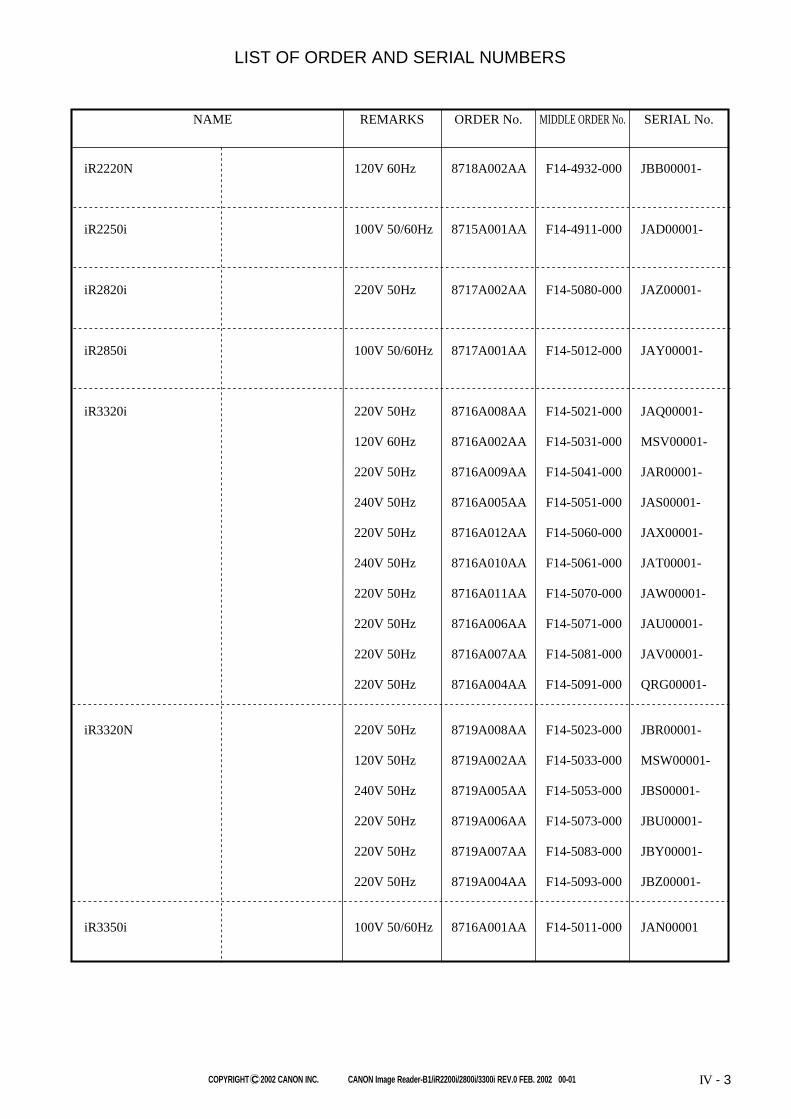
COPYRIGHT C 2002 CANON INC. CANON Image Reader-B1/iR2200i/2800i/3300i REV.0 FEB. 2002 00-01 IV - 3
iR2220N 120V 60Hz 8718A002AA F14-4932-000 JBB00001-
iR2250i 100V 50/60Hz 8715A001AA F14-4911-000 JAD00001-
iR2820i 220V 50Hz 8717A002AA F14-5080-000 JAZ00001-
iR2850i 100V 50/60Hz 8717A001AA F14-5012-000 JAY00001-
iR3320i 220V 50Hz 8716A008AA F14-5021-000 JAQ00001-
120V 60Hz 8716A002AA F14-5031-000 MSV00001-
220V 50Hz 8716A009AA F14-5041-000 JAR00001-
240V 50Hz 8716A005AA F14-5051-000 JAS00001-
220V 50Hz 8716A012AA F14-5060-000 JAX00001-
240V 50Hz 8716A010AA F14-5061-000 JAT00001-
220V 50Hz 8716A011AA F14-5070-000 JAW00001-
220V 50Hz 8716A006AA F14-5071-000 JAU00001-
220V 50Hz 8716A007AA F14-5081-000 JAV00001-
220V 50Hz 8716A004AA F14-5091-000 QRG00001-
iR3320N 220V 50Hz 8719A008AA F14-5023-000 JBR00001-
120V 50Hz 8719A002AA F14-5033-000 MSW00001-
240V 50Hz 8719A005AA F14-5053-000 JBS00001-
220V 50Hz 8719A006AA F14-5073-000 JBU00001-
220V 50Hz 8719A007AA F14-5083-000 JBY00001-
220V 50Hz 8719A004AA F14-5093-000 JBZ00001-
iR3350i 100V 50/60Hz 8716A001AA F14-5011-000 JAN00001
LIST OF ORDER AND SERIAL NUMBERS
NAME REMARKS MIDDLE ORDER No.ORDER No. SERIAL No.

COPYRIGHT C 2002 CANON INC. CANON Image Reader-B1/iR2200i/2800i/3300i REV.0 FEB. 2002 00-01 IV - 5
CONTENTS
B1.
B2.
B3.
B4.
B5.
B6.
B7.
D2.
LIST OF CONNECTORS
LIST OF MOTORS
LIST OF FAN MOTORS
LIST OF SENSORS
LIST OF CLUTCHES, AND OTHERS
LIST OF HEATERS, LAMPS, ETC.
LIST OF PCBS
NUMERICAL INDEX
(iR2200i/2800i/3300i/2220i/2250i/2820i
/2850i/3320i/3350i/2220N/3320N)
A.
100.
101.
102.
103.
104.
105.
106.
107.
110.
111.
120.
130.
190.
191.
250.
260.
261.
280.
300.
310.
315.
320.
330.
350.
351.
360.
460.
500.
640.
810.
900.
910.
920.
921.
930.
940.
950.
ASSEMBLY LOCATION DIAGRAM
EXTERNAL COVERS, PANELS, ETC.
MACHINE FRONT PLATE
INTERNAL COMPONENTS 1
INTERNAL COMPONENTS 2
INTERNAL COMPONENTS 3
INTERNAL COMPONENTS 4
INTERNAL COMPONENTS 5
MACHINE REAR PLATE
POWER CORD TERMINAL ASSEMBLY(100/120V)
POWER CORD TERMINAL ASSEMBLY(220/240V)
RIGHT DOOR ASSEMBLY
CONTROL PANEL ASSEMBLY
DEVELOPING FAN ASSEMBLY
MACHINE EXHAUST FAN ASSEMBLY
MAIN DRIVE ASSEMBLY
PAPER PICK-UP DRIVE ASSEMBLY
DUPLEXING DRIVE ASSEMBLY
FIXING FEEDER DRIVE ASSEMBLY
CASSETTE
PAPER PICK-UP MOUNT ASSEMBLY
MULTI FEEDER TRAY ASSEMBLY
REGISTRATION FRONT GUIDE ASSEMBLY
PAPER FEEDER ASSEMBLY
PAPER DELIVERY ASSEMBLY
LEFT VERTICAL PATH ASSEMBLY
DUPLEXING FEEDER ASSEMBLY
SCANNER ASSEMBLY
DRUM CARTRIDGE ASSEMBLY
DEVELOPING ASSEMBLY
FIXING ASSEMBLY
CONTROLLER BOX ASSEMBLY
HV POWER SUPPLY PCB ASSEMBLY
CONTROL PANEL CPU PCB ASSEMBLY
CONTROL PANEL INVERTER PCB ASSEMBLY
DC CONTROLLER PCB ASSEMBLY
PAPER PICK-UP PCB ASSEMBLY
RESOLUTION CONVERSION PCB ASSEMBLY

COPYRIGHT C 2002 CANON INC. CANON Image Reader-B1/iR2200i/2800i/3300i REV.0 FEB. 2002 00-01
FIGURE 100 EXTERNAL COVERS, PANELS, ETC.
EXCEPT ACC TYPE
220/240V
49120V
120V
4
56
2
1
38
39
40
12
503
31
30
8
3
15
9
11
1027
26
507
16
23
24 25
22
22
501
21
20
22
19
2218
17
504
33
35
32
37
36
34
505
43
45
502
502
502
29
502
42
7
14
44
49502
502
502
502
14
13
13
41502
502
506
47
46
28
48
502
100-1

FIGURE&
KEY NO.PART NUMBER DESCRIPTION SERIAL NUMBER / REMARKS
RANK
Q’TY
COPYRIGHT C 2002 CANON INC. CANON Image Reader-B1/iR2200i/2800i/3300i REV.0 FEB. 2002 00-01 100-2
100 - NPN RF EXTERNAL COVERS, PANELS, ETC
1 FB5-4769-000 1 PANEL, RIGHT LOWER
2 FB5-5055-000 1 PANEL, PRINTER, UPPER
3 FB5-5058-000 1 PANEL, SUPPORT, LEFT
4 FB5-5063-000 1 PANEL, INTERNAL, REAR
5 FB5-5182-000 1 PANEL, LEFT SUPPORT, REAR
6 FB5-5186-030 1 PANEL, PAPER DELIVERY
7 FB3-2224-000 2 PIN, HINGE
8 FB5-5266-020 1 LEFT PANEL, MIDDLE
9 FB5-5267-000 1 LEFT PANEL, REAR
10 FB5-4731-000 1 PLATE, BLANKING
11 FB5-4741-030 1 RIGHT PANEL, FRONT
12 FB5-4767-000 1 RIGHT PANEL, MIDDLE
13 FB5-4772-000 2 LINK, TRAY
14 FS7-2404-000 2 SPRING, COMPRESSION
15 FB5-4731-000 1 PLATE, BLANKING
16 FB5-4768-000 1 RIGHT PANEL, REAR
17 FG6-5736-000 1 PANEL, FRONT
18 FB5-5053-000 1 PLATE, SWITCH SHAFT PRESSURE
19 FB5-5067-000 1 PLATE, SHUTTER LEVER PRESSURE
20 FB5-5069-000 1 PLATE, INTERLOCK
21 FB5-5070-000 1 PLATE, CATCH, LEFT
22 XA9-0605-000 4 SCREW,P,M4X8
23 FB4-5380-000 1 BRUSH, CLEANING
24 FB5-5052-000 1 CASE, SERVICE
25 FF6-0074-020 1 MIRROR CLEANING TOOL
26 FB1-7157-000 1 COVER, BLANKING, REAR
27 FB5-5061-000 1 PANEL, REAR
28 FB6-2852-000 2 COVER, RUBBER
29 FS5-9661-000 1 SCREW,STEPPED,RS,M4

FIGURE&
KEY NO.PART NUMBER DESCRIPTION SERIAL NUMBER / REMARKS
RANK
Q’TY
COPYRIGHT C 2002 CANON INC. CANON Image Reader-B1/iR2200i/2800i/3300i REV.0 FEB. 2002 00-01
100 - 30 FB5-5057-000 1 PANEL, WASTE TONER
31 XD9-0206-000 1 SPACER, SCREW RETAINER
32 FB1-7737-000 1 TABLE, DOCUMENT, UPPER
33 FB1-7738-000 1 TABLE, DOCUMENT, LOWER
34 FB5-9806-000 1 SUPPORT, COPY TRAY
35 XA9-1301-000 2 SCREW, RS STEPPED, M4
36 FB4-5933-000 1 TRAY, DOCUMENT
37 FB5-5143-000 1 TRAY, PAPER DELIVERY AUXILIARY
38 FB5-4859-000 1 PANEL, PAPER DELIVERY
39 FB5-4860-000 1 GUIDE, PAPER DELIVERY
40 XA9-0605-000 3 SCREW,P,M4X8
41 RS6-8382-000 1 LABEL, "WARNING LASER"
42 FB6-4433-000 1 EMBLEM IR2200I
FB6-4434-000 1 EMBLEM IR2800I
FB6-4435-000 1 EMBLEM IR3300I
FB6-4436-000 1 EMBLEM IMAGE RUNNER 3300I
FB6-5907-000 1 EMBLEM IR2250I
FB6-5908-000 1 EMBLEM IR2850I
FB6-5909-000 1 EMBLEM IR3350I
FB6-5910-000 1 EMBLEM IR2220I 120V
FB6-5911-000 1 EMBLEM IR3320I 120V
FB6-5912-000 1 EMBLEM IR2220N
FB6-5913-000 1 EMBLEM IR3320N 120V
FB6-5914-000 1 EMBLEM IR2220I 220/240V
FB6-5915-000 1 EMBLEM IR2820I
FB6-5916-000 1 EMBLEM IR3320I 220/240V
FB6-5918-000 1 EMBLEM IR3320N 220/240V
43 XA9-0266-000 7 SCREW,W/WASHER,M4X8
44 RS6-8382-000 1 LABEL, "WARNING LASER"
45 FB5-5068-000 1 PLATE, BLANKING EXCEPT ACC TYPE
100-3

FIGURE&
KEY NO.PART NUMBER DESCRIPTION SERIAL NUMBER / REMARKS
RANK
Q’TY
COPYRIGHT C 2002 CANON INC. CANON Image Reader-B1/iR2200i/2800i/3300i REV.0 FEB. 2002 00-01
100 - 46 FB3-2381-000 1 COVER, PAPER PICK-UP, LOWER 220/240V
47 FB5-5066-000 1 PANEL, UPPER
48 FH2-5824-000 1 COVER, CONNECTOR, 1
49 FB5-0332-000 2 LABEL,"WARNING,LASER" 120V
501 XB3-6400-805 1 SCREW,RS,M4X8
502 XB3-6400-800 AR SCREW,RS,M4X8
503 XB3-6400-800 1 SCREW,RS,M4X8
504 XB4-7300-609 2 SCREW,TAPPING,TRUSS HEAD,M3X6
505 XB6-7401-206 2 SCREW,TP,M4X12
506 XB4-7400-809 2 SCREW,TAPPING,TRUSS HEAD,M4X8 220/240V
507 XB3-6400-800 7 SCREW,RS,M4X8
100-4

COPYRIGHT C 2002 CANON INC. CANON Image Reader-B1/iR2200i/2800i/3300i REV.0 FEB. 2002 00-01900-1
FIGURE 900 CONTROLLER BOX ASSEMBLY
SEE FIGURE E90
B
NOT SERVICE PART
100V
(J1019)
(J2005)
(J1017)
(J1004)
(J1003)
(BAT1001)
(J1060)
A
B
A
SEE FIGURE 950
(J1061)
(J9203)
(J1015)
(J9201)
120/220/240V
iR2200i/2800i/3300i
(J1028)
6
1
2
503
501
502
503
2
4
13
3
501
10
8
7
9
501
503
11
12
20
21
15
16
18
22
17
19
8

FIGURE&
KEY NO.PART NUMBER DESCRIPTION SERIAL NUMBER / REMARKS
RANK
Q’TY
COPYRIGHT C 2002 CANON INC. CANON Image Reader-B1/iR2200i/2800i/3300i REV.0 FEB. 2002 00-01
900 - NPN RF CONTROLLER BOX ASSEMBLY
1 FF3-4199-000 1 CABLE, CC-4 J1060
2 RB1-7067-000 2 RAIL, GUIDE
3 FG3-2232-060 1 MAIN CONTROLLER PCB ASSEMBLY IR2200I/2800I/3300I
FG3-2492-000 1 MAIN CONTROLLER PCB ASSEMBLY IR2220I/2220N/2250IIR2820I/2850I/3320I
IR3320N/3350I
4 FG3-1744-020 1 CENTRO PCB ASSEMBLY J1019
6 FF3-4191-000 1 CABLE, FLAT, HD J1017,2005
7 FG3-1994-000 1 CABLE, FLAT J1015,9201
8 WE8-5925-000 1 CORE, FERRITE
9 FG3-2238-000 1 CABLE, POWER SUPPLY J1061,9203
10 FG6-5831-000 1 DIFFERENTIAL PCB ASSEMBLY
11 WA7-2376-000 1 DIMM, SMS-6486M-H, SD-RAM IR2200I/2800I/3300IJ1004
12 WA7-2322-000 1 DIMM,M366S1723DTS-C7A,SDRAM IR2200I/2800I/3300IJ1003
WA7-2372-000 1 DIMM, MT16LSDT3264AG-133E1 IR2220I/2220N/2250IIR2820I/2850I/3320I
IR3320N/3350IJ1003
13 WK1-5019-000 1 BATTERY,LITHIUM,CR2477-HE4H,3V BAT1001
15 FG6-5964-000 1 ETHERNET BOARD PCB ASSEMBLY
16 FG6-5795-000 1 RISER BOARD PCB ASSEMBLY
17 FG3-2959-000 1 LIPS BOARD PCB ASSEMBLY 100V
18 FH5-3127-000 1 DIMM ASS'Y 100V
19 FB5-6612-000 1 PLATE, PCB FIXING 100V
20 FG3-2478-000 1 CD-ROM, USER SOFTWARE 220/240V
FG3-2772-000 1 CD-ROM, USER SOFTWARE 100V
FH5-3378-000 1 CD-ROM, USER SOFT WEAR US/UK 120V
21 FG3-2484-000 1 CD-ROM, N/W SCANGEAR 100V
FH5-3381-000 1 CD-ROM, N/W SCAN GEAR 120/220/240V
22 FG3-3057-000 1 CD-ROM, FAX DRIVER
23 FF3-4219-000 1 SHORT CONNECTOR J1028
501 XB1-2300-607 10 SCREW,MACH.,TRUSS HEAD,M3X6
900-2

FIGURE&
KEY NO.PART NUMBER DESCRIPTION SERIAL NUMBER / REMARKS
RANK
Q’TY
COPYRIGHT C 2002 CANON INC. CANON Image Reader-B1/iR2200i/2800i/3300i REV.0 FEB. 2002 00-01
900 - 502 XB4-7400-807 2 SCREW,TAPPING,TRUSS HEAD,M4X8
503 XB1-2300-607 8 SCREW,MACH.,TRUSS HEAD,M3X6
IC1003 FH4-6123-000 1 IC, M38871M2-010GP, MCU
IC1005 FH4-6145-000 1 IC, GATE ARRAY
IC1009 FH4-6085-000 1 IC, SLA902FM2J, GATE ARRAY
900-3

COPYRIGHT C 2002 CANON INC. CANON Image Reader-B1/iR2200i/2800i/3300i REV.0 FEB. 2002 00-01 G-1

COPYRIGHT C 2002 CANON INC. CANON Image Reader-B1/iR2200i/2800i/3300i REV.0 FEB. 2002 00-01G-2
USB APPLICATION INTERFACE BOARD-B1 8749A002AA F61-8908-000
LIST OF ORDER AND SERIAL NUMBERS
NAME REMARKS MIDDLE ORDER No.ORDER No. SERIAL No.

COPYRIGHT C 2002 CANON INC. CANON Image Reader-B1/iR2200i/2800i/3300i REV.0 FEB. 2002 00-01
CONTENTS
GA.
G92.
D10.
ASSEMBLY LOCATION DIAGRAM
USB INTERFACE BOARD PCB ASSEMBLY
NUMERICAL INDEX
G-3

COPYRIGHT C 2002 CANON INC. CANON Image Reader-B1/iR2200i/2800i/3300i REV.0 FEB. 2002 00-01
FIGURE GA ASSEMBLY LOCATION DIAGRAM
USB INTERFACE BOARD PCB ASSEMBLY
G92
GA-1

FIGURE&
KEY NO.PART NUMBER DESCRIPTION SERIAL NUMBER / REMARKS
RANK
Q’TY
COPYRIGHT C 2002 CANON INC. CANON Image Reader-B1/iR2200i/2800i/3300i REV.0 FEB. 2002 00-01
FIGURE G92 USB INTERFACE BOARD PCB ASSEMBLY
G92-1
G92 - FG6-5024-000 1 USB INTERFACE BOARD PCB ASS'Y
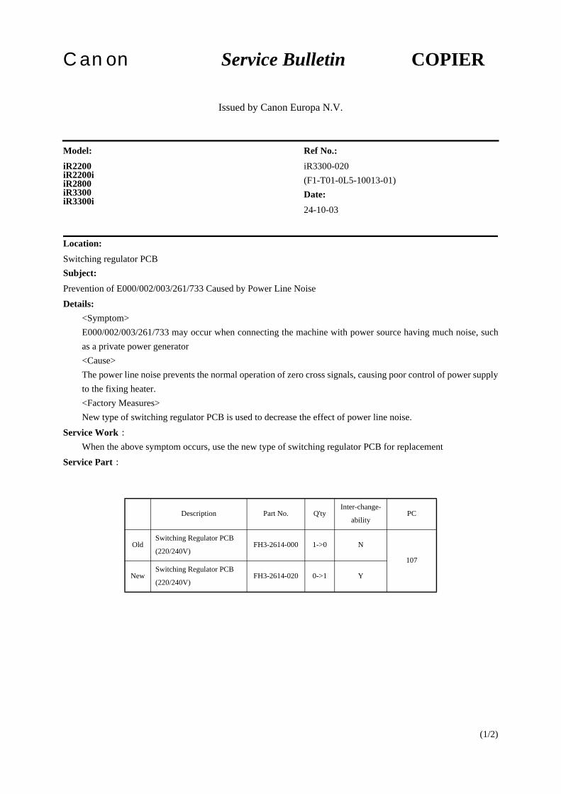
(1/2)
Canon Service Bulletin COPIER
Issued by Canon Europa N.V.
Location:Switching regulator PCBSubject:Prevention of E000/002/003/261/733 Caused by Power Line NoiseDetails:
<Symptom>E000/002/003/261/733 may occur when connecting the machine with power source having much noise, suchas a private power generator<Cause>The power line noise prevents the normal operation of zero cross signals, causing poor control of power supplyto the fixing heater.<Factory Measures>New type of switching regulator PCB is used to decrease the effect of power line noise.
Service Work:When the above symptom occurs, use the new type of switching regulator PCB for replacement
Service Part:
Model:iR2200iR2200iiR2800iR3300iR3300i
Ref No.:iR3300-020(F1-T01-0L5-10013-01)Date:24-10-03
Description Part No. Q'tyInter-change-
abilityPC
OldSwitching Regulator PCB
(220/240V)FH3-2614-000 1->0 N
107
NewSwitching Regulator PCB
(220/240V)FH3-2614-020 0->1 Y

iR3300-020
(2/2)
Affected Machines:Model Destination Serial NoiR2200 230V AMS UHK24214 and lateriR2200i 230V AMS UJB01604 and lateriR2800 230V AMS UHM09227 and lateriR3300 230V AMS UHL10540 and lateriR3300i 230V AMS UJC01732 and lateriR2200 230V UK QEF11194 and lateriR2200i 230V UK QEV00295 and lateriR2800 230V UK QEH04236 and lateriR3300 230V UK QEG05414 and lateriR3300i 230V UK QEW00304 and lateriR2200 230V GER TDS10720 and lateriR2200i 230V GER TEG01970 and lateriR2800 230V GER TDU02368 and lateriR3300 230V GER TDT03579 and lateriR3300i 230V GER TEH00888 and lateriR2200 230V FRN SDD15119 and lateriR2200i 230V FRN SDT00666 and lateriR2800 230V FRN SDJ04239 and lateriR3300 230V FRN SDF06223 and lateriR3300i 230V FRN SDU00775 and lateriR2200 230V ITA PSQ02166 and lateriR2200i 230V ITA QSZ00132 and lateriR2800 230V ITA PST00800 and lateriR3300 230V ITA PSS06211 and lateriR3300i 230V ITA RSC00446 and later

(1/1)
Canon Service Bulletin COPIER
Issued by Canon Europa N.V.
Location:Service Manual (FY8-13H8-010)Subject:Correction of the descriptions "Configuration with Accessories" (p 1-17S)
Descriptions about machines that the Power Supply-N1 can be installed and an accessory that the Power Supply-N1is required for its installation are added.
Model:iR2200iR2200iiR2800iR3300iR3300i
Ref No.:iR3300-021(F1-T01-0L5-10049-01)Date:27-02-04

- 1 / 3 -
Service Bulletin
Issued by Canon Europa N.V.
Model : No.:
DATE:
GP-GEN-121
(FF-T01-K9-000035-01)
(FF-T01-L4-000006-01)
(FF-T01-L5-000011-01)
21.12.01
Location : Hard Disk Drive
Subject : Information of E602 troubleshooting
Reason : This bulletin notifies of servicing procedure to be followed if E602 error (HD-related error) occurred on an
iR machine
Details :E602 errors on iR machines are classified into the following errors by the subcode and corresponding cause:
(1) E602-0001A HD mount error was detected when the HD was started up.
(2) E602-0002A HD data read error was detected when the HD was started up.
(3) E602-0003
The data address registered on the HD is not consistent with the data. (Write-abort error on HD sector)
(Note) Partitions on iR machine
1) Image storage areaSaves and stores image data.
2) General-purpose file storage areaStores user setting data, various log data, PDL spool data, and image data address.
3) PDL-related file storage areaStores font data for printers.
4) Firmware storage areaStores system software.
(a) If write to the image storage area was abortedA function is implemented to fix a write-abort error in the image storage area, which automaticallyrepairs the error after power is turned off and switched on again. (The function writes dummy dataat locations specified by the data pointer to fix address-data inconsistency.)If a write-abort error occurred in the image storage area and E602-0003 is output, turn off the mainpower and then turn it on again to fix the error. (See Note 1.)
COPIER
iR2200-3300iR5000-6000/iR5000i-6000iiR105/7200/85/8500

GP-GEN-121
- 2 / 3 -
(b) If write to other areas than the image storage area was abortedIf write to other areas than the image storage area was aborted, the automatic recovery function isunable to fix it. Follow the procedure below to manually recover the sector.
(i) If the machine can be entered service mode- Enter service mode and set "0" for COPIER > FUNCTIONS > SYSTEM > HD-CHECK.(This will check and recover the entire sectors on the HD.) (This takes about 20 to 40 minutesdepending on the HD capacity.)- After executing HD-CHECK, turn the power off and turn it on again to check that the HDstarts up normally. If the HD fails to start up, set "1" and then "2" for HD-CLEAR.("1" initializes the image storage area; "2" the general-purpose file storage area.)- After recovering from the write-abort error, reinstall system software.
(ii) If the machine cannot enter service mode
E602-0003 may appear after power-on on a machine in a state incapable of entering service mode.(This occurs if write-abort error is detected during self-diagnosis after power-on.)In this case, turn on the main power while holding down digit keys 1 and 9 at the same time.This activates a function that is equivalent to setting "0" for HD-CHECK in service mode.After calling up the function, see "If the machine can enter service mode" above and do as you do afterentering service mode.
Remarks :(1) Causes of write-abort errors
As a rule, write-abort error results from inconsistency between the address (data pointer) and the data.The address-data consistency is broken by turning power off at illegal timings.
iR machines access their HD at the timings below, not to mention when copying and/or writing of PDL data.If the main power is turned off coinciding with any of the following events, the E602-0003 error occurs.
i) 150 ms of initial process within 1 minute after a jobAn iR machine performs internal process in the main unit for a duration of 150 ms at undetermined timingwithin 1 minute after completion of a copy/fax/print job. (During the internal process in the main unit, thecontroller accesses the image data address files on the HD.)
At what point in the 1-minute time span the process starts is undetermined. If the main power is turned onduring the 150 ms, The E602-0003 code may appear when the power is turned on next time.
ii) 19 ms of inquiry from NetSpotIf an inquiry for job history information is sent from NetSpot on a PC to the copier, the HD makes writingoperation for about 19 ms. Turning off the main power within this duration may cause E602-0003 whenthe power is turned on next time.
iii) Operation of remote UIThe HD makes writing operation also when remote UI is working. Turning off the main power within the durationmay cause E602-0003 when the power is turned on next time.

GP-GEN-121
- 3 / 3 -
Cautions :(1) Note 1: Automatic recovery from write-abort error in the image storage area by main power off/on
This function is supported by the following versions of system software.iR5000: v15.xx or later (v14.02 and previous versions sometimes took an E602-0003 error for an E602-0001error. -> Official release is scheduled in late February in 2002 and Beta version will be released in lateDecember.)
iR2200: v6.01 or lateriR8500: v7.01 or laterOther models: Initial mass-production versions
(2) Note: Recovery of sectors by holding down 1+9 during power-on
This function is supported by the following versions of boot ROM.iR5000: v13.53 -> Release is scheduled in early December in 2001.Other models: v7.25